EP4528089A2 - Air intake for an aircraft propulsion system engine assembly - Google Patents
Air intake for an aircraft propulsion system engine assembly Download PDFInfo
- Publication number
- EP4528089A2 EP4528089A2 EP24202672.2A EP24202672A EP4528089A2 EP 4528089 A2 EP4528089 A2 EP 4528089A2 EP 24202672 A EP24202672 A EP 24202672A EP 4528089 A2 EP4528089 A2 EP 4528089A2
- Authority
- EP
- European Patent Office
- Prior art keywords
- air
- air intake
- circumferential end
- circumferential
- wall portion
- Prior art date
- Legal status (The legal status is an assumption and is not a legal conclusion. Google has not performed a legal analysis and makes no representation as to the accuracy of the status listed.)
- Pending
Links
Images



Classifications
-
- F—MECHANICAL ENGINEERING; LIGHTING; HEATING; WEAPONS; BLASTING
- F02—COMBUSTION ENGINES; HOT-GAS OR COMBUSTION-PRODUCT ENGINE PLANTS
- F02C—GAS-TURBINE PLANTS; AIR INTAKES FOR JET-PROPULSION PLANTS; CONTROLLING FUEL SUPPLY IN AIR-BREATHING JET-PROPULSION PLANTS
- F02C7/00—Features, components parts, details or accessories, not provided for in, or of interest apart form groups F02C1/00 - F02C6/00; Air intakes for jet-propulsion plants
- F02C7/04—Air intakes for gas-turbine plants or jet-propulsion plants
-
- F—MECHANICAL ENGINEERING; LIGHTING; HEATING; WEAPONS; BLASTING
- F02—COMBUSTION ENGINES; HOT-GAS OR COMBUSTION-PRODUCT ENGINE PLANTS
- F02C—GAS-TURBINE PLANTS; AIR INTAKES FOR JET-PROPULSION PLANTS; CONTROLLING FUEL SUPPLY IN AIR-BREATHING JET-PROPULSION PLANTS
- F02C7/00—Features, components parts, details or accessories, not provided for in, or of interest apart form groups F02C1/00 - F02C6/00; Air intakes for jet-propulsion plants
- F02C7/04—Air intakes for gas-turbine plants or jet-propulsion plants
- F02C7/05—Air intakes for gas-turbine plants or jet-propulsion plants having provisions for obviating the penetration of damaging objects or particles
- F02C7/055—Air intakes for gas-turbine plants or jet-propulsion plants having provisions for obviating the penetration of damaging objects or particles with intake grids, screens or guards
-
- B—PERFORMING OPERATIONS; TRANSPORTING
- B64—AIRCRAFT; AVIATION; COSMONAUTICS
- B64C—AEROPLANES; HELICOPTERS
- B64C27/00—Rotorcraft; Rotors peculiar thereto
- B64C27/04—Helicopters
- B64C27/12—Rotor drives
-
- B—PERFORMING OPERATIONS; TRANSPORTING
- B64—AIRCRAFT; AVIATION; COSMONAUTICS
- B64D—EQUIPMENT FOR FITTING IN OR TO AIRCRAFT; FLIGHT SUITS; PARACHUTES; ARRANGEMENT OR MOUNTING OF POWER PLANTS OR PROPULSION TRANSMISSIONS IN AIRCRAFT
- B64D33/00—Arrangement in aircraft of power plant parts or auxiliaries not otherwise provided for
- B64D33/02—Arrangement in aircraft of power plant parts or auxiliaries not otherwise provided for of combustion air intakes
-
- B—PERFORMING OPERATIONS; TRANSPORTING
- B64—AIRCRAFT; AVIATION; COSMONAUTICS
- B64D—EQUIPMENT FOR FITTING IN OR TO AIRCRAFT; FLIGHT SUITS; PARACHUTES; ARRANGEMENT OR MOUNTING OF POWER PLANTS OR PROPULSION TRANSMISSIONS IN AIRCRAFT
- B64D35/00—Transmitting power from power plants to propellers or rotors; Arrangements of transmissions
- B64D35/04—Transmitting power from power plants to propellers or rotors; Arrangements of transmissions characterised by the transmission driving a plurality of propellers or rotors
-
- F—MECHANICAL ENGINEERING; LIGHTING; HEATING; WEAPONS; BLASTING
- F02—COMBUSTION ENGINES; HOT-GAS OR COMBUSTION-PRODUCT ENGINE PLANTS
- F02C—GAS-TURBINE PLANTS; AIR INTAKES FOR JET-PROPULSION PLANTS; CONTROLLING FUEL SUPPLY IN AIR-BREATHING JET-PROPULSION PLANTS
- F02C7/00—Features, components parts, details or accessories, not provided for in, or of interest apart form groups F02C1/00 - F02C6/00; Air intakes for jet-propulsion plants
- F02C7/36—Power transmission arrangements between the different shafts of the gas turbine plant, or between the gas-turbine plant and the power user
-
- B—PERFORMING OPERATIONS; TRANSPORTING
- B64—AIRCRAFT; AVIATION; COSMONAUTICS
- B64D—EQUIPMENT FOR FITTING IN OR TO AIRCRAFT; FLIGHT SUITS; PARACHUTES; ARRANGEMENT OR MOUNTING OF POWER PLANTS OR PROPULSION TRANSMISSIONS IN AIRCRAFT
- B64D33/00—Arrangement in aircraft of power plant parts or auxiliaries not otherwise provided for
- B64D33/02—Arrangement in aircraft of power plant parts or auxiliaries not otherwise provided for of combustion air intakes
- B64D2033/0266—Arrangement in aircraft of power plant parts or auxiliaries not otherwise provided for of combustion air intakes specially adapted for particular type of power plants
- B64D2033/0293—Arrangement in aircraft of power plant parts or auxiliaries not otherwise provided for of combustion air intakes specially adapted for particular type of power plants for turboprop engines
-
- F—MECHANICAL ENGINEERING; LIGHTING; HEATING; WEAPONS; BLASTING
- F05—INDEXING SCHEMES RELATING TO ENGINES OR PUMPS IN VARIOUS SUBCLASSES OF CLASSES F01-F04
- F05D—INDEXING SCHEME FOR ASPECTS RELATING TO NON-POSITIVE-DISPLACEMENT MACHINES OR ENGINES, GAS-TURBINES OR JET-PROPULSION PLANTS
- F05D2220/00—Application
- F05D2220/30—Application in turbines
- F05D2220/32—Application in turbines in gas turbines
- F05D2220/323—Application in turbines in gas turbines for aircraft propulsion, e.g. jet engines
-
- F—MECHANICAL ENGINEERING; LIGHTING; HEATING; WEAPONS; BLASTING
- F05—INDEXING SCHEMES RELATING TO ENGINES OR PUMPS IN VARIOUS SUBCLASSES OF CLASSES F01-F04
- F05D—INDEXING SCHEME FOR ASPECTS RELATING TO NON-POSITIVE-DISPLACEMENT MACHINES OR ENGINES, GAS-TURBINES OR JET-PROPULSION PLANTS
- F05D2250/00—Geometry
- F05D2250/50—Inlet or outlet
- F05D2250/51—Inlet
Definitions
- This disclosure relates generally to engine assemblies configured for aircraft propulsion systems and, more particularly, to an air intake for an engine assembly.
- a propulsion system for an aircraft may include an air intake configured to direct ambient air into a gas turbine engine of the propulsion system.
- Various air intake configurations are known in the art for directing air into a propulsion system gas turbine engine. While these known air intakes have various advantages, there is still room in the art for improvement.
- an engine assembly for an aircraft propulsion system includes a gas turbine engine, a gearbox, and a first drive shaft.
- the gas turbine engine includes an engine output shaft, and air intake, and a compressor.
- the engine output shaft is configured for rotation about a first rotational axis.
- the air intake includes an air intake body forming an air inlet, an air outlet, and an air plenum extending between and connecting the air inlet and the air outlet in fluid communication.
- the air plenum extends circumferentially about the engine output shaft between and to a first circumferential end of the air intake and a second circumferential end of the air intake.
- the first circumferential end and the second circumferential end form a circumferential gap outside of the air intake and circumferentially between the first circumferential end and the second circumferential end.
- the compressor is connected in fluid communication with the air intake at the air outlet.
- the gearbox includes a gear assembly operably connected to the engine output shaft.
- the first drive shaft is operably connected to the gear assembly.
- the first drive shaft is rotatable about a second rotational axis.
- the second rotational axis is radially offset from the first rotational axis.
- the first drive shaft extends along the second rotational axis through the circumferential gap.
- At least a portion of the first drive shaft may be disposed radially inside the air intake body.
- the air intake may further include a screen.
- the screen may extend circumferentially within the air plenum from the first circumferential end to the second circumferential end.
- At least a portion of the first drive shaft may be disposed radially inside the screen.
- the engine assembly may further include a second drive shaft operably connected to the gear assembly.
- the second drive shaft may be rotatable about a third rotational axis.
- the third rotational axis may be radially offset from the first rotational axis.
- the third rotational axis and the second rotational axis may be colinear.
- the air intake body may form the air inlet at a first circumferential position of the air intake.
- first circumferential end and the second circumferential end may form the circumferential gap at a second circumferential position circumferentially opposite the first circumferential position.
- the air intake may include an end strut forming the first circumferential end and the second circumferential end.
- the air intake body may include an outer radial wall portion.
- the outer radial wall portion may be radially offset from the air outlet.
- a radial distance between the outer radial wall portion and the air outlet may decrease in a circumferential direction from the air inlet to the first circumferential end and from the air inlet to the second circumferential end.
- the air intake may further include at least one guide strut disposed within the air plenum.
- an air intake for an aircraft propulsion system engine assembly includes an air intake body.
- the air intake body extends circumferentially about an axis.
- the air intake body forms an air inlet, an air outlet, and an air plenum extending between and connecting the air inlet and the air outlet in fluid communication.
- the air plenum extends circumferentially about the axis between and to a first circumferential end of the air intake and a second circumferential end of the air intake.
- the air intake body includes an air inlet body portion, a first wall portion, a second wall portion, and an outer radial wall portion.
- the air inlet body portion forms the air inlet at a first circumferential position of the air intake.
- the first wall portion and the second wall portion extend circumferentially from the air inlet body portion to the first circumferential end.
- the first wall portion and the second wall portion extend circumferentially from the air inlet body portion to the second circumferential end.
- the first wall portion and the second wall portion form the air plenum and the air outlet between the first wall portion and the second wall portion.
- the outer radial wall portion extends along the first wall portion and the second wall portion and further forms the air plenum.
- the outer radial wall portion extends circumferentially from the air inlet body portion to the first circumferential end.
- the outer radial wall portion extends circumferentially from the air inlet body portion to the second circumferential end.
- first circumferential end and the second circumferential end may form a circumferential gap outside of the air intake and circumferentially between the first circumferential end and the second circumferential end.
- first circumferential end and the second circumferential end may form the circumferential gap at a second circumferential position circumferentially opposite the first circumferential position.
- the air intake may include an end strut extending between and connecting the first wall portion, the second wall portion, and the outer radial wall portion.
- the end strut maty form the first circumferential end and the second circumferential end.
- an engine assembly for an aircraft propulsion system includes a gas turbine engine and a drive shaft.
- the gas turbine engine includes an air intake and a compressor.
- the air intake includes an air intake body extending circumferentially about an axis.
- the air intake body forms an air inlet, an air outlet, and an air plenum extending between and connecting the air inlet and the air outlet in fluid communication.
- the air intake body forms the air inlet at a first circumferential position of the air intake.
- the air plenum extends circumferentially about the axis between and to a first circumferential end of the air intake and a second circumferential end of the air intake.
- the first circumferential end and the second circumferential end form a circumferential gap outside of the air intake and circumferentially between the first circumferential end and the second circumferential end.
- the first circumferential end and the second circumferential end form the circumferential gap at a second circumferential position of the air intake circumferentially opposite the first circumferential position.
- the compressor is connected in fluid communication with the air intake at the air outlet.
- the drive shaft is rotatable about a rotational axis.
- the rotational axis is radially offset from the axis.
- the drive shaft extends along the rotational axis through the circumferential gap.
- At least a portion of the drive shaft may be disposed radially inside the air intake body.
- the air intake may further include a screen.
- the screen may extend circumferentially within the air plenum from the first circumferential end to the second circumferential end.
- At least a portion of the drive shaft may be disposed radially inside the screen.
- FIG. 1 illustrates a perspective view of an aircraft 1000 including a propulsion system 10.
- the aircraft 1000 of FIG. 1 is configured as a rotary-wing aircraft (e.g., a helicopter).
- the present disclosure is also applicable to other configurations of aircraft such as, but not limited to, a fixed-wing aircraft (e.g., an airplane), a tilt-rotor aircraft, a tilt-wing aircraft, or another aerial vehicle.
- the propulsion system 10 of FIG. 1 is configured to drive rotation of a main rotor 1002 and a tail rotor 1004 of the aircraft 1000 to facilitate propulsion for the aircraft 1000.
- the aircraft 1000 of FIG. 1 further includes a housing 1006 (e.g., a nacelle, a fuselage, etc.) enclosing and forming a protective outer covering for the propulsion system 10.
- a housing 1006 e.g., a nacelle, a fuselage, etc.
- FIG. 2 schematically illustrates a cutaway, side view of the propulsion system 10.
- the propulsion system 10 of FIG. 2 includes an engine assembly 20.
- the engine assembly 20 includes a gas turbine engine 22, an engine transmission gearbox 24, a main rotor drive shaft 26, a main rotor gearbox 28, a tail rotor drive shaft 30, a tail rotor gearbox 32, and an air intake 34.
- FIG. 3 schematically illustrates a cutaway, side view of the gas turbine engine 22.
- the gas turbine engine 22 of FIG. 3 includes a compressor section 36, a combustor section 38, a turbine section 40, and an engine static structure 42.
- the compressor section 36 includes a compressor 44.
- the combustor section 38 includes a combustor 46 (e.g., an annular combustor).
- the turbine section 40 includes a high-pressure turbine 48 and a power turbine 50.
- the gas turbine engine 22 sections 36, 38, 40 of FIG. 3 are sequentially arranged along an axial centerline 52 (e.g., a rotational axis) of the gas turbine engine 22.
- the engine static structure 42 may include, for example, one or more engine cases for the gas turbine engine 22.
- the engine static structure 42 may additionally include cowlings, bearing assemblies, or other structural components of the gas turbine engine 22.
- the engine static structure 42 houses and structurally supports the engine sections 36, 38, 40.
- Components of the engine sections 26, 28, 30 form a first rotational assembly 54 (e.g., a high-pressure spool) and a second rotational assembly 56 (e.g., a power spool).
- the first rotational assembly 54 and the second rotational assembly 56 are mounted for rotation about the axial centerline 52 relative to the engine static structure 42.
- the first rotational assembly 54 includes a first shaft 58, a bladed compressor rotor 60 for the compressor 44, and a bladed first turbine rotor 62 for the high-pressure turbine 48.
- the first shaft 58 interconnects the bladed compressor rotor 60 and the bladed first turbine rotor 62.
- the second rotational assembly 56 includes a second shaft 64 and a bladed second turbine rotor 66 for the power turbine 50.
- the second shaft 64 is a power shaft (e.g., an engine output shaft) of the gas turbine engine 22.
- the second shaft 64 interconnects the bladed second turbine rotor 66 with the engine transmission gearbox 24.
- the first shaft 58 and the second shaft 64 are concentric and configured to rotate about the axial centerline 52. The present disclosure, however, is not limited to concentric configurations of the first shaft 58 and the second shaft 64.
- ambient air is directed into the compressor section 36 by the air intake 34.
- the air is compressed in the compressor 44 by the bladed compressor rotor 60 and directed into a combustion chamber of the combustor 46.
- Fuel is injected into the combustion chamber and mixed with the compressed air to provide a fuel-air mixture.
- This fuel-air mixture is ignited and combustion products thereof flow through and sequentially cause the bladed first turbine rotor 62 and the bladed second turbine rotor 66 to rotate.
- the rotation of the bladed first turbine rotor 62 and the bladed second turbine rotor 66 respectively drives rotation of the first rotational assembly 54 and the second rotational assembly 56.
- the engine transmission gearbox 24 of FIG. 2 includes a gear assembly 68.
- the gear assembly 68 is operably connected to (e.g., coupled with) the second shaft 64, the main rotor drive shaft 26, and the tail rotor drive shaft 30.
- the gas turbine engine 22 is configured to drive rotation of the main rotor drive shaft 26 and the tail rotor drive shaft 30 with the second shaft 64 through the gear assembly 68.
- the gear assembly 68 operably connects the second shaft 64, the main rotor drive shaft 26, and the tail rotor drive shaft 30.
- the gear assembly 68 may be configured, for example, an offset gear assembly, an epicyclic gear assembly (e.g., a planetary gear assembly), or another suitable gear assembly for operably connecting the second shaft 64, the main rotor drive shaft 26, and the tail rotor drive shaft 30.
- an offset gear assembly e.g., an offset gear assembly
- an epicyclic gear assembly e.g., a planetary gear assembly
- another suitable gear assembly for operably connecting the second shaft 64, the main rotor drive shaft 26, and the tail rotor drive shaft 30.
- the present disclosure is not limited to any particular gear configuration for the gear assembly 68.
- the main rotor drive shaft 26 operably interconnects (e.g., couples) the engine transmission gearbox 24 (e.g., the gear assembly 68) with the main rotor gearbox 28.
- the main rotor drive shaft 26 may extend in an axially forward direction from the engine transmission gearbox 24 to the main rotor gearbox 28 (e.g., relative to the axial centerline 52).
- the main rotor drive shaft 26 extends along a rotational axis 70 between and to a first axial end 72 of the main rotor drive shaft 26 and a second axial end 74 of the main rotor drive shaft 26.
- the main rotor drive shaft 26 is rotatable about the rotational axis 70.
- the rotational axis 70 may extend parallel to or substantially parallel to the axial centerline 52. The present disclosure, however, is not limited to any particular orientation of the rotational axis 70 relative to the axial centerline 52.
- the main rotor drive shaft 26 and its rotational axis 70 may be radially offset from the second shaft 64 (e.g., with respect to the axial centerline 52).
- the main rotor drive shaft 26 may be disposed vertically below the second shaft 64 as shown, for example, in FIG. 2 .
- the present disclosure is not limited to any particular vertical position of the main rotor drive shaft 26 relative to the second shaft 64.
- the main rotor drive shaft 26 may be coupled with the gear assembly 68 at (e.g., on, adjacent, or proximate) the first axial end 72.
- the main rotor drive shaft 26 may be coupled with a gear assembly 76 of the main rotor gearbox 28 at (e.g., on, adjacent, or proximate) the second axial end 74.
- the gear assembly 76 is further operably connected to (e.g., coupled with) the main rotor 1002 (see FIG. 1 ) to drive rotation of the main rotor 1002 in response to rotation of the main rotor drive shaft 26.
- the tail rotor drive shaft 30 operably interconnects (e.g., couples) the engine transmission gearbox 24 (e.g., the gear assembly 68) with the tail rotor gearbox 32.
- the tail rotor drive shaft 30 may extend in an axially aft direction from the engine transmission gearbox 24 to the tail rotor gearbox 32 (e.g., relative to the axial centerline 52).
- the tail rotor drive shaft 30 is disposed axially and radially coincident with the air intake 34, relative to the axial centerline 52.
- the tail rotor drive shaft 30 extends along a rotational axis 78 between and to a first axial end 80 of the tail rotor drive shaft 30 and a second axial end 82 of the tail rotor drive shaft 30.
- the tail rotor drive shaft 30 is rotatable about the rotational axis 78.
- the rotational axis 78 may extend parallel to or substantially parallel to the axial centerline 52.
- the rotational axis 78 may additionally extend parallel to, substantially parallel to, or colinear with the rotational axis 70.
- the present disclosure is not limited to any particular orientation of the rotational axis 78 relative to the axial centerline 52 or the rotational axis 70.
- the tail rotor drive shaft 30 and its rotational axis 78 are radially offset from the second shaft 64 (e.g., with respect to the axial centerline 52).
- the tail rotor drive shaft 30 may be disposed vertically below the second shaft 64 as shown, for example, in FIG. 2 .
- the present disclosure is not limited to any particular vertical position of the tail rotor drive shaft 30 relative to the second shaft 64.
- the tail rotor drive shaft 30 may be coupled with the gear assembly 68 at (e.g., on, adjacent, or proximate) the first axial end 80.
- the first axial end 80 may be disposed axially forward of the air intake 34.
- the tail rotor drive shaft 30 may be coupled with a gear assembly 84 of the tail rotor gearbox 32 at (e.g., on, adjacent, or proximate) the second axial end 82.
- the second axial end 82 may be disposed axially aft of the air intake 34.
- the gear assembly 84 is further operably connected to (e.g., coupled with) the tail rotor 1004 (see FIG. 1 ) to drive rotation of the tail rotor 1004 in response to rotation of the tail rotor drive shaft 30.
- the main rotor drive shaft 26 and the tail rotor drive shaft 30 may be formed by a single drive shaft extending through the engine transmission gearbox 24 along the rotational axis 70 and the rotational axis 78 (e.g., colinear rotational axes). Accordingly, the single drive shaft forming the main rotor drive shaft 26 and the tail rotor drive shaft 30 may extend between and to the second axial end 74 and the second axial end 82.
- the single drive shaft may be coupled with the gear assembly 76 at (e.g., on, adjacent, or proximate) the second axial end 74.
- the single drive shaft may be coupled with the gear assembly 84 at (e.g., on, adjacent, or proximate) the second axial end 82.
- the single drive shaft may be coupled with the gear assembly 68 at (e.g., on, adjacent, or proximate) an axially-intermediate portion of the single drive shaft between the second axial end 74 and the second axial end
- FIG. 4 schematically illustrates a front, cutaway view of the air intake 34, the second shaft 64, and the tail rotor drive shaft 30.
- FIG. 5 schematically illustrates a side, cutaway view of the air intake 34, the second shaft 64, the tail rotor drive shaft 30, and portions of the compressor section 36.
- the air intake 34 includes an air intake body 86.
- the air intake 34 may additionally include a screen 102.
- the air intake body 86 forms an air inlet 88, an air outlet 90, and an air plenum 92 of the air intake 34.
- the air inlet 88 is disposed at (e.g., on, adjacent, or proximate) an exterior of the propulsion system 10 (see FIG. 2 ). Ambient air outside the propulsion system 10 enters the air intake 34 at the air inlet 88.
- the air outlet 90 is disposed at (e.g., on, adjacent, or proximate) the compressor section 36 (e.g., an air inlet of the compressor 44) (see FIG. 3 ). Air from the air intake 34 flows into the compressor 44 through the air outlet 90.
- the air plenum 92 extends between and connects the air inlet 88 and the air outlet 90 in fluid communication.
- the air intake body 86 may be formed by a single (e.g., unitary) component. Alternatively, the air intake body 86 may include a plurality of components assembled together to form the air intake body 86.
- the air intake body 86 of FIGS. 4 and 5 includes an air inlet body portion 94, a first wall portion 96, a second wall portion 98, and an outer radial wall portion 100.
- the air inlet body portion 94 is disposed at a circumferential position of the air intake 34 (e.g., relative to the axial centerline 52).
- the air inlet body portion 94 of FIGS. 4 and 5 may be understood to be disposed at a vertical top position (e.g., a 12 o'clock position) of the air intake 34.
- the air inlet body portion 94 surrounds and forms the air inlet 88 and directs ambient air through the air inlet 88 and into the air plenum 92.
- the first wall portion 96, the second wall portion 98, and the outer radial wall portion 100 surround and form the air plenum 92.
- the first wall portion 96, the second wall portion 98, and the outer radial wall portion 100 extend circumferentially from the air inlet body portion 94 to a first circumferential end 104 of air intake 34 and a second circumferential end 106 of the air intake 34, relative to the axial centerline 52.
- the first wall portion 96 and the second wall portion 98 may curve from a radial orientation toward an axial orientation in a direction from the air inlet 88 to the air outlet 90.
- the first wall portion 96 may be disposed axially forward of the second wall portion 98 at (e.g., on, adjacent, or proximate) the air inlet 88 and the first wall portion 96 may be disposed radially inward of the second wall portion 98 at (e.g., on, adjacent, or proximate) the air outlet 90.
- the first wall portion 96 may converge toward the second wall portion 98 in a direction from the air inlet 88 to the air outlet 90, however, the present disclosure is not limited to this particular configuration of the air intake body 86.
- the outer radial wall portion 100 extends circumferentially along the first wall portion 96 and the second wall portion 98 forming an outer radial boundary of the air plenum 92.
- the first circumferential end 104 and the second circumferential end 106 enclose and form opposing circumferential ends of the air plenum 92.
- the first circumferential end 104 and the second circumferential end 106 form a circumferential gap 108 between the first circumferential end 104 and the second circumferential end 106.
- the circumferential gap 108 extends circumferentially between and to the first circumferential end 104 and the second circumferential end 106 outside of the air intake 34.
- the first circumferential end 104 and the second circumferential end 106 may form the circumferential gap 108 at a circumferential position of the air intake 34 (e.g., relative to the axial centerline 52) which is circumferentially opposite the air inlet body portion 94 and the air inlet 88.
- the circumferential gap 108 of FIG. 4 may be understood to be disposed at a vertical bottom position (e.g., a 6 o'clock position) of the air intake 34.
- the air intake 34 may include an end strut 110 forming the first circumferential end 104 and the second circumferential end 106.
- the end strut 110 may also form the circumferential gap 108.
- the end strut 110 may extend between and connect the first wall portion 96, the second wall portion 98, and the outer radial wall portion 100 at (e.g., on, adjacent, or proximate) the first circumferential end 104 to enclose (e.g., seal) the air plenum 92 at the first circumferential end 104.
- the end strut 110 may extend between and connect the first wall portion 96, the second wall portion 98, and the outer radial wall portion 100 at (e.g., on, adjacent, or proximate) the second circumferential end 106 to enclose (e.g., seal) the air plenum 92 at the second circumferential end 106.
- the end strut 110 may extend radially or substantially radially from the outer radial wall portion 100 toward the axial centerline 52. The present disclosure, however, is not limited to any particular orientation of the end strut 110 relative to the axial centerline 52.
- the first circumferential end 104 and the second circumferential end 106 may alternatively be formed by portions of the air intake body 86.
- the air intake 34 may include the screen 102 disposed within the air plenum 92.
- the screen 102 may extend circumferentially within the air plenum 92 between and to the first circumferential end 104 and the second circumferential end 106.
- the screen 102 may extend circumferentially between and to the end strut 110 at (e.g., on, adjacent, or proximate) the first circumferential end 104 and the end strut 110 at (e.g., on, adjacent, or proximate) the second circumferential end 106.
- the screen 102 may extend axially within the air plenum 92 between and to the first wall portion 96 and the second wall portion 98.
- the screen 102 is disposed between the air inlet 88 and the air outlet 90 with respect to an air flow path through the air intake 34 and into the compressor section 36 (see FIG. 3 ).
- the screen 102 may be formed, for example, by a wire mesh, a perforated plate, or other porous structure configured to prevent larger particulate entering the air inlet 88 from flowing to the air outlet 90.
- the tail rotor drive shaft 30 extends through the circumferential gap 108 between (e.g., axially between) the first axial end 80 and the second axial end 82.
- the tail rotor drive shaft 30 is positioned within the circumferential gap 108 and circumferentially adjacent the first circumferential end 104 (e.g., the end strut 110) and the second circumferential end 106 (e.g., the end strut 112).
- at least a portion of the tail rotor drive shaft 30 disposed in the circumferential gap 108 may be radially inside of the outer radial wall portion 100.
- all of the tail rotor drive shaft 30 disposed in the circumferential gap 108 may be radially inside of the outer radial wall portion 100.
- at least a portion of the tail rotor drive shaft 30 disposed in the circumferential gap 108 may be radially inside of the screen 102.
- the circumferential gap 108 formed by the air intake 34 and the position of the tail rotor drive shaft 30 within the circumferential gap 108 facilitates a reduction in radial distance D1 between the axial centerline 52 and the rotational axis 78 (e.g., the tail rotor drive shaft 30), relative to a conventional air intake which extends fully, circumferentially about (e.g., completely around) an axial centerline and/or engine output shaft of a gas turbine engine. Accordingly, the present disclosure air intake facilitates a more radially-compact engine assembly 20. The more radially-compact engine assembly 20 facilitates a reduction in size and/or material of the housing 1006 (see FIG.
- the size of the housing 1006 may further facilitate a reduction in aerodynamic drag for the propulsion system 10 and the aircraft 1000 (see FIG. 1 ).
- air intake 34 may form the circumferential gap 108 at this position circumferentially opposite the air inlet 88 and, therefore, may have a negligible impact on air flow supplied to the compressor section 36 (see FIG. 3 ).
- the air intake 34 may be configured with the outer radial wall portion 100 radially offset relative to the air outlet 90.
- a radial distance D2 between the outer radial wall portion 100 and the air outlet 90 may decrease in a circumferential direction from the air inlet 88 to the first circumferential end 104 and from the air inlet 88 to the second circumferential end 106.
- This configuration of the air intake 34 of FIG. 6 may facilitate improved air flow distribution at the air outlet 90.
- the air intake 34 of FIG. 6 may facilitate more circumferentially uniform air flow supplied to the compressor section 36 (see FIG. 3 ) (e.g., the compressor entry face) with respect to air pressure, air flow rate, and air swirl.
- the air intake 34 may include one or more guide struts 114 disposed within the air plenum 92.
- the guide struts 114 may be formed by or otherwise connected to the air intake body 86.
- the guide struts 114 may be circumferentially distributed throughout the air plenum 92.
- FIGS. 7A-B illustrate cutaway views of one of the guide struts 114 projecting outward from the second wall portion 98.
- Each of the guide struts 114 may extend between and connect the first wall portion 96 and the second wall portion 98 (see FIG. 5 ). Some or all of the guide struts 114 may extend through the first wall portion 96 and connect to the gearbox 24 (see FIG.
- the guide struts 114 may be structural struts connecting the gearbox 24 and the gas turbine engine 22 (e.g., the engine static structure 42; see FIG. 3 ) through the air intake 34. As shown in FIGS. 7A-B , the guide struts 114 may be oriented to induce swirl or otherwise direct air flow in the air plenum 92 in a clockwise or counterclockwise direction to control air flow and air distribution within the air plenum 92.
- any one of these structures may describe the operations as a sequential process, many of the operations can be performed in parallel or concurrently.
- the order of the operations may be rearranged.
- a process may correspond to a method, a function, a procedure, a subroutine, a subprogram, etc.
Landscapes
- Engineering & Computer Science (AREA)
- Chemical & Material Sciences (AREA)
- Combustion & Propulsion (AREA)
- Mechanical Engineering (AREA)
- General Engineering & Computer Science (AREA)
- Aviation & Aerospace Engineering (AREA)
- Structures Of Non-Positive Displacement Pumps (AREA)
Abstract
Description
- This disclosure relates generally to engine assemblies configured for aircraft propulsion systems and, more particularly, to an air intake for an engine assembly.
- A propulsion system for an aircraft may include an air intake configured to direct ambient air into a gas turbine engine of the propulsion system. Various air intake configurations are known in the art for directing air into a propulsion system gas turbine engine. While these known air intakes have various advantages, there is still room in the art for improvement.
- It should be understood that any or all of the features or embodiments described herein can be used or combined in any combination with each and every other feature or embodiment described herein unless expressly noted otherwise.
- According to an aspect of the present disclosure, an engine assembly for an aircraft propulsion system includes a gas turbine engine, a gearbox, and a first drive shaft. The gas turbine engine includes an engine output shaft, and air intake, and a compressor. The engine output shaft is configured for rotation about a first rotational axis. The air intake includes an air intake body forming an air inlet, an air outlet, and an air plenum extending between and connecting the air inlet and the air outlet in fluid communication. The air plenum extends circumferentially about the engine output shaft between and to a first circumferential end of the air intake and a second circumferential end of the air intake. The first circumferential end and the second circumferential end form a circumferential gap outside of the air intake and circumferentially between the first circumferential end and the second circumferential end. The compressor is connected in fluid communication with the air intake at the air outlet. The gearbox includes a gear assembly operably connected to the engine output shaft. The first drive shaft is operably connected to the gear assembly. The first drive shaft is rotatable about a second rotational axis. The second rotational axis is radially offset from the first rotational axis. The first drive shaft extends along the second rotational axis through the circumferential gap.
- In any of the aspects or embodiments described above and herein, at least a portion of the first drive shaft may be disposed radially inside the air intake body.
- In any of the aspects or embodiments described above and herein, the air intake may further include a screen. The screen may extend circumferentially within the air plenum from the first circumferential end to the second circumferential end.
- In any of the aspects or embodiments described above and herein, at least a portion of the first drive shaft may be disposed radially inside the screen.
- In any of the aspects or embodiments described above and herein, the engine assembly may further include a second drive shaft operably connected to the gear assembly. The second drive shaft may be rotatable about a third rotational axis. The third rotational axis may be radially offset from the first rotational axis.
- In any of the aspects or embodiments described above and herein, the third rotational axis and the second rotational axis may be colinear.
- In any of the aspects or embodiments described above and herein, the air intake body may form the air inlet at a first circumferential position of the air intake.
- In any of the aspects or embodiments described above and herein, the first circumferential end and the second circumferential end may form the circumferential gap at a second circumferential position circumferentially opposite the first circumferential position.
- In any of the aspects or embodiments described above and herein, the air intake may include an end strut forming the first circumferential end and the second circumferential end.
- In any of the aspects or embodiments described above and herein, the air intake body may include an outer radial wall portion. The outer radial wall portion may be radially offset from the air outlet.
- In any of the aspects or embodiments described above and herein, a radial distance between the outer radial wall portion and the air outlet may decrease in a circumferential direction from the air inlet to the first circumferential end and from the air inlet to the second circumferential end.
- In any of the aspects or embodiments described above and herein, the air intake may further include at least one guide strut disposed within the air plenum.
- According to another aspect of the present disclosure, an air intake for an aircraft propulsion system engine assembly includes an air intake body. The air intake body extends circumferentially about an axis. The air intake body forms an air inlet, an air outlet, and an air plenum extending between and connecting the air inlet and the air outlet in fluid communication. The air plenum extends circumferentially about the axis between and to a first circumferential end of the air intake and a second circumferential end of the air intake. The air intake body includes an air inlet body portion, a first wall portion, a second wall portion, and an outer radial wall portion. The air inlet body portion forms the air inlet at a first circumferential position of the air intake. The first wall portion and the second wall portion extend circumferentially from the air inlet body portion to the first circumferential end. The first wall portion and the second wall portion extend circumferentially from the air inlet body portion to the second circumferential end. The first wall portion and the second wall portion form the air plenum and the air outlet between the first wall portion and the second wall portion. The outer radial wall portion extends along the first wall portion and the second wall portion and further forms the air plenum. The outer radial wall portion extends circumferentially from the air inlet body portion to the first circumferential end. The outer radial wall portion extends circumferentially from the air inlet body portion to the second circumferential end.
- In any of the aspects or embodiments described above and herein, the first circumferential end and the second circumferential end may form a circumferential gap outside of the air intake and circumferentially between the first circumferential end and the second circumferential end.
- In any of the aspects or embodiments described above and herein, the first circumferential end and the second circumferential end may form the circumferential gap at a second circumferential position circumferentially opposite the first circumferential position.
- In any of the aspects or embodiments described above and herein, the air intake may include an end strut extending between and connecting the first wall portion, the second wall portion, and the outer radial wall portion. The end strut maty form the first circumferential end and the second circumferential end.
- According to another aspect of the present disclosure, an engine assembly for an aircraft propulsion system includes a gas turbine engine and a drive shaft. The gas turbine engine includes an air intake and a compressor. The air intake includes an air intake body extending circumferentially about an axis. The air intake body forms an air inlet, an air outlet, and an air plenum extending between and connecting the air inlet and the air outlet in fluid communication. The air intake body forms the air inlet at a first circumferential position of the air intake. The air plenum extends circumferentially about the axis between and to a first circumferential end of the air intake and a second circumferential end of the air intake. The first circumferential end and the second circumferential end form a circumferential gap outside of the air intake and circumferentially between the first circumferential end and the second circumferential end. The first circumferential end and the second circumferential end form the circumferential gap at a second circumferential position of the air intake circumferentially opposite the first circumferential position. The compressor is connected in fluid communication with the air intake at the air outlet. The drive shaft is rotatable about a rotational axis. The rotational axis is radially offset from the axis. The drive shaft extends along the rotational axis through the circumferential gap.
- In any of the aspects or embodiments described above and herein, at least a portion of the drive shaft may be disposed radially inside the air intake body.
- In any of the aspects or embodiments described above and herein, the air intake may further include a screen. The screen may extend circumferentially within the air plenum from the first circumferential end to the second circumferential end.
- In any of the aspects or embodiments described above and herein, at least a portion of the drive shaft may be disposed radially inside the screen.
- The present disclosure, and all its aspects, embodiments and advantages associated therewith will become more readily apparent in view of the detailed description provided below, including the accompanying drawings.
-
-
FIG. 1 illustrates a perspective view of an aircraft including a propulsion system, in accordance with one or more embodiments of the present disclosure. -
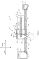
FIG. 2 schematically illustrates a side, cutaway view of an engine assembly for an aircraft propulsion system, in accordance with one or more embodiments of the present disclosure. -
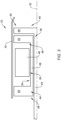
FIG. 3 schematically illustrates a side, cutaway view of a gas turbine engine for an aircraft propulsion system, in accordance with one or more embodiments of the present disclosure. -
FIG. 4 schematically illustrates a front, cutaway view of an air intake for the engine assembly ofFIG. 2 , in accordance with one or more embodiments of the present disclosure. -
FIG. 5 schematically illustrates a side, cutaway view of the air intake ofFIG. 4 , in accordance with one or more embodiments of the present disclosure. -
FIG. 6 schematically illustrates a front, cutaway view of another air intake for the engine assembly ofFIG. 2 , in accordance with one or more embodiments of the present disclosure. -
FIGS. 7A-B illustrate perspective, cutaway views of a portion of an air intake including a guide strut, in accordance with one or more embodiments of the present disclosure. -
FIG. 1 illustrates a perspective view of anaircraft 1000 including apropulsion system 10. Theaircraft 1000 ofFIG. 1 is configured as a rotary-wing aircraft (e.g., a helicopter). The present disclosure, however, is also applicable to other configurations of aircraft such as, but not limited to, a fixed-wing aircraft (e.g., an airplane), a tilt-rotor aircraft, a tilt-wing aircraft, or another aerial vehicle. Thepropulsion system 10 ofFIG. 1 is configured to drive rotation of amain rotor 1002 and atail rotor 1004 of theaircraft 1000 to facilitate propulsion for theaircraft 1000. Theaircraft 1000 ofFIG. 1 further includes a housing 1006 (e.g., a nacelle, a fuselage, etc.) enclosing and forming a protective outer covering for thepropulsion system 10. -
FIG. 2 schematically illustrates a cutaway, side view of thepropulsion system 10. Thepropulsion system 10 ofFIG. 2 includes anengine assembly 20. Theengine assembly 20 includes agas turbine engine 22, anengine transmission gearbox 24, a mainrotor drive shaft 26, amain rotor gearbox 28, a tailrotor drive shaft 30, atail rotor gearbox 32, and anair intake 34. -
FIG. 3 schematically illustrates a cutaway, side view of thegas turbine engine 22. Thegas turbine engine 22 ofFIG. 3 includes acompressor section 36, acombustor section 38, a turbine section 40, and an enginestatic structure 42. Thecompressor section 36 includes acompressor 44. Thecombustor section 38 includes a combustor 46 (e.g., an annular combustor). The turbine section 40 includes a high-pressure turbine 48 and apower turbine 50. Thegas turbine engine 22sections FIG. 3 are sequentially arranged along an axial centerline 52 (e.g., a rotational axis) of thegas turbine engine 22. The enginestatic structure 42 may include, for example, one or more engine cases for thegas turbine engine 22. The enginestatic structure 42 may additionally include cowlings, bearing assemblies, or other structural components of thegas turbine engine 22. The enginestatic structure 42 houses and structurally supports theengine sections - Components of the
engine sections rotational assembly 54 and the secondrotational assembly 56 are mounted for rotation about theaxial centerline 52 relative to the enginestatic structure 42. - The first
rotational assembly 54 includes afirst shaft 58, abladed compressor rotor 60 for thecompressor 44, and a bladedfirst turbine rotor 62 for the high-pressure turbine 48. Thefirst shaft 58 interconnects the bladedcompressor rotor 60 and the bladedfirst turbine rotor 62. - The second
rotational assembly 56 includes asecond shaft 64 and a bladedsecond turbine rotor 66 for thepower turbine 50. Thesecond shaft 64 is a power shaft (e.g., an engine output shaft) of thegas turbine engine 22. Thesecond shaft 64 interconnects the bladedsecond turbine rotor 66 with theengine transmission gearbox 24. Thefirst shaft 58 and thesecond shaft 64 are concentric and configured to rotate about theaxial centerline 52. The present disclosure, however, is not limited to concentric configurations of thefirst shaft 58 and thesecond shaft 64. - During operation of the
gas turbine engine 22, ambient air is directed into thecompressor section 36 by theair intake 34. The air is compressed in thecompressor 44 by the bladedcompressor rotor 60 and directed into a combustion chamber of thecombustor 46. Fuel is injected into the combustion chamber and mixed with the compressed air to provide a fuel-air mixture. This fuel-air mixture is ignited and combustion products thereof flow through and sequentially cause the bladedfirst turbine rotor 62 and the bladedsecond turbine rotor 66 to rotate. The rotation of the bladedfirst turbine rotor 62 and the bladedsecond turbine rotor 66 respectively drives rotation of the firstrotational assembly 54 and the secondrotational assembly 56. - Referring again to
FIG. 2 , theengine transmission gearbox 24 ofFIG. 2 includes agear assembly 68. Thegear assembly 68 is operably connected to (e.g., coupled with) thesecond shaft 64, the mainrotor drive shaft 26, and the tailrotor drive shaft 30. Thegas turbine engine 22 is configured to drive rotation of the mainrotor drive shaft 26 and the tailrotor drive shaft 30 with thesecond shaft 64 through thegear assembly 68. Thegear assembly 68 operably connects thesecond shaft 64, the mainrotor drive shaft 26, and the tailrotor drive shaft 30. Thegear assembly 68 may be configured, for example, an offset gear assembly, an epicyclic gear assembly (e.g., a planetary gear assembly), or another suitable gear assembly for operably connecting thesecond shaft 64, the mainrotor drive shaft 26, and the tailrotor drive shaft 30. The present disclosure, however, is not limited to any particular gear configuration for thegear assembly 68. - The main
rotor drive shaft 26 operably interconnects (e.g., couples) the engine transmission gearbox 24 (e.g., the gear assembly 68) with themain rotor gearbox 28. The mainrotor drive shaft 26 may extend in an axially forward direction from theengine transmission gearbox 24 to the main rotor gearbox 28 (e.g., relative to the axial centerline 52). The mainrotor drive shaft 26 extends along arotational axis 70 between and to a firstaxial end 72 of the mainrotor drive shaft 26 and a secondaxial end 74 of the mainrotor drive shaft 26. The mainrotor drive shaft 26 is rotatable about therotational axis 70. Therotational axis 70 may extend parallel to or substantially parallel to theaxial centerline 52. The present disclosure, however, is not limited to any particular orientation of therotational axis 70 relative to theaxial centerline 52. The mainrotor drive shaft 26 and itsrotational axis 70 may be radially offset from the second shaft 64 (e.g., with respect to the axial centerline 52). The mainrotor drive shaft 26 may be disposed vertically below thesecond shaft 64 as shown, for example, inFIG. 2 . The present disclosure, however, is not limited to any particular vertical position of the mainrotor drive shaft 26 relative to thesecond shaft 64. As used herein, the term "vertical" and associated orientational language such as "vertically above," "vertically below," "up," and "down" should be understood with respect to a normal attitude of thepropulsion system 10. The mainrotor drive shaft 26 may be coupled with thegear assembly 68 at (e.g., on, adjacent, or proximate) the firstaxial end 72. The mainrotor drive shaft 26 may be coupled with agear assembly 76 of themain rotor gearbox 28 at (e.g., on, adjacent, or proximate) the secondaxial end 74. Thegear assembly 76 is further operably connected to (e.g., coupled with) the main rotor 1002 (seeFIG. 1 ) to drive rotation of themain rotor 1002 in response to rotation of the mainrotor drive shaft 26. - The tail
rotor drive shaft 30 operably interconnects (e.g., couples) the engine transmission gearbox 24 (e.g., the gear assembly 68) with thetail rotor gearbox 32. The tailrotor drive shaft 30 may extend in an axially aft direction from theengine transmission gearbox 24 to the tail rotor gearbox 32 (e.g., relative to the axial centerline 52). As will be discussed in further detail, the tailrotor drive shaft 30 is disposed axially and radially coincident with theair intake 34, relative to theaxial centerline 52. The tailrotor drive shaft 30 extends along arotational axis 78 between and to a firstaxial end 80 of the tailrotor drive shaft 30 and a secondaxial end 82 of the tailrotor drive shaft 30. The tailrotor drive shaft 30 is rotatable about therotational axis 78. Therotational axis 78 may extend parallel to or substantially parallel to theaxial centerline 52. Therotational axis 78 may additionally extend parallel to, substantially parallel to, or colinear with therotational axis 70. The present disclosure, however, is not limited to any particular orientation of therotational axis 78 relative to theaxial centerline 52 or therotational axis 70. The tailrotor drive shaft 30 and itsrotational axis 78 are radially offset from the second shaft 64 (e.g., with respect to the axial centerline 52). The tailrotor drive shaft 30 may be disposed vertically below thesecond shaft 64 as shown, for example, inFIG. 2 . The present disclosure, however, is not limited to any particular vertical position of the tailrotor drive shaft 30 relative to thesecond shaft 64. The tailrotor drive shaft 30 may be coupled with thegear assembly 68 at (e.g., on, adjacent, or proximate) the firstaxial end 80. The firstaxial end 80 may be disposed axially forward of theair intake 34. The tailrotor drive shaft 30 may be coupled with agear assembly 84 of thetail rotor gearbox 32 at (e.g., on, adjacent, or proximate) the secondaxial end 82. The secondaxial end 82 may be disposed axially aft of theair intake 34. Thegear assembly 84 is further operably connected to (e.g., coupled with) the tail rotor 1004 (seeFIG. 1 ) to drive rotation of thetail rotor 1004 in response to rotation of the tailrotor drive shaft 30. - The main
rotor drive shaft 26 and the tailrotor drive shaft 30 may be formed by a single drive shaft extending through theengine transmission gearbox 24 along therotational axis 70 and the rotational axis 78 (e.g., colinear rotational axes). Accordingly, the single drive shaft forming the mainrotor drive shaft 26 and the tailrotor drive shaft 30 may extend between and to the secondaxial end 74 and the secondaxial end 82. The single drive shaft may be coupled with thegear assembly 76 at (e.g., on, adjacent, or proximate) the secondaxial end 74. The single drive shaft may be coupled with thegear assembly 84 at (e.g., on, adjacent, or proximate) the secondaxial end 82. The single drive shaft may be coupled with thegear assembly 68 at (e.g., on, adjacent, or proximate) an axially-intermediate portion of the single drive shaft between the secondaxial end 74 and the secondaxial end 82. -
FIG. 4 schematically illustrates a front, cutaway view of theair intake 34, thesecond shaft 64, and the tailrotor drive shaft 30.FIG. 5 schematically illustrates a side, cutaway view of theair intake 34, thesecond shaft 64, the tailrotor drive shaft 30, and portions of thecompressor section 36. - The
air intake 34 includes anair intake body 86. Theair intake 34 may additionally include ascreen 102. Theair intake body 86 forms anair inlet 88, anair outlet 90, and anair plenum 92 of theair intake 34. Theair inlet 88 is disposed at (e.g., on, adjacent, or proximate) an exterior of the propulsion system 10 (seeFIG. 2 ). Ambient air outside thepropulsion system 10 enters theair intake 34 at theair inlet 88. Theair outlet 90 is disposed at (e.g., on, adjacent, or proximate) the compressor section 36 (e.g., an air inlet of the compressor 44) (seeFIG. 3 ). Air from theair intake 34 flows into thecompressor 44 through theair outlet 90. Theair plenum 92 extends between and connects theair inlet 88 and theair outlet 90 in fluid communication. Theair intake body 86 may be formed by a single (e.g., unitary) component. Alternatively, theair intake body 86 may include a plurality of components assembled together to form theair intake body 86. - The
air intake body 86 ofFIGS. 4 and 5 includes an airinlet body portion 94, afirst wall portion 96, asecond wall portion 98, and an outerradial wall portion 100. The airinlet body portion 94 is disposed at a circumferential position of the air intake 34 (e.g., relative to the axial centerline 52). For example, the airinlet body portion 94 ofFIGS. 4 and 5 may be understood to be disposed at a vertical top position (e.g., a 12 o'clock position) of theair intake 34. The airinlet body portion 94 surrounds and forms theair inlet 88 and directs ambient air through theair inlet 88 and into theair plenum 92. Thefirst wall portion 96, thesecond wall portion 98, and the outerradial wall portion 100 surround and form theair plenum 92. Thefirst wall portion 96, thesecond wall portion 98, and the outerradial wall portion 100 extend circumferentially from the airinlet body portion 94 to a firstcircumferential end 104 ofair intake 34 and a secondcircumferential end 106 of theair intake 34, relative to theaxial centerline 52. Thefirst wall portion 96 and thesecond wall portion 98 may curve from a radial orientation toward an axial orientation in a direction from theair inlet 88 to theair outlet 90. For example, thefirst wall portion 96 may be disposed axially forward of thesecond wall portion 98 at (e.g., on, adjacent, or proximate) theair inlet 88 and thefirst wall portion 96 may be disposed radially inward of thesecond wall portion 98 at (e.g., on, adjacent, or proximate) theair outlet 90. Thefirst wall portion 96 may converge toward thesecond wall portion 98 in a direction from theair inlet 88 to theair outlet 90, however, the present disclosure is not limited to this particular configuration of theair intake body 86. The outerradial wall portion 100 extends circumferentially along thefirst wall portion 96 and thesecond wall portion 98 forming an outer radial boundary of theair plenum 92. - The first
circumferential end 104 and the secondcircumferential end 106 enclose and form opposing circumferential ends of theair plenum 92. The firstcircumferential end 104 and the secondcircumferential end 106 form acircumferential gap 108 between the firstcircumferential end 104 and the secondcircumferential end 106. In other words, thecircumferential gap 108 extends circumferentially between and to the firstcircumferential end 104 and the secondcircumferential end 106 outside of theair intake 34. The firstcircumferential end 104 and the secondcircumferential end 106 may form thecircumferential gap 108 at a circumferential position of the air intake 34 (e.g., relative to the axial centerline 52) which is circumferentially opposite the airinlet body portion 94 and theair inlet 88. For example, thecircumferential gap 108 ofFIG. 4 may be understood to be disposed at a vertical bottom position (e.g., a 6 o'clock position) of theair intake 34. - The
air intake 34 may include anend strut 110 forming the firstcircumferential end 104 and the secondcircumferential end 106. Theend strut 110 may also form thecircumferential gap 108. Theend strut 110 may extend between and connect thefirst wall portion 96, thesecond wall portion 98, and the outerradial wall portion 100 at (e.g., on, adjacent, or proximate) the firstcircumferential end 104 to enclose (e.g., seal) theair plenum 92 at the firstcircumferential end 104. Similarly, theend strut 110 may extend between and connect thefirst wall portion 96, thesecond wall portion 98, and the outerradial wall portion 100 at (e.g., on, adjacent, or proximate) the secondcircumferential end 106 to enclose (e.g., seal) theair plenum 92 at the secondcircumferential end 106. Theend strut 110 may extend radially or substantially radially from the outerradial wall portion 100 toward theaxial centerline 52. The present disclosure, however, is not limited to any particular orientation of theend strut 110 relative to theaxial centerline 52. The firstcircumferential end 104 and the secondcircumferential end 106 may alternatively be formed by portions of theair intake body 86. - The
air intake 34 may include thescreen 102 disposed within theair plenum 92. Thescreen 102 may extend circumferentially within theair plenum 92 between and to the firstcircumferential end 104 and the secondcircumferential end 106. For example, thescreen 102 may extend circumferentially between and to theend strut 110 at (e.g., on, adjacent, or proximate) the firstcircumferential end 104 and theend strut 110 at (e.g., on, adjacent, or proximate) the secondcircumferential end 106. Thescreen 102 may extend axially within theair plenum 92 between and to thefirst wall portion 96 and thesecond wall portion 98. Thescreen 102 is disposed between theair inlet 88 and theair outlet 90 with respect to an air flow path through theair intake 34 and into the compressor section 36 (seeFIG. 3 ). Thescreen 102 may be formed, for example, by a wire mesh, a perforated plate, or other porous structure configured to prevent larger particulate entering theair inlet 88 from flowing to theair outlet 90. - Referring again to
FIGS. 2 ,4, and 5 , the tailrotor drive shaft 30 extends through thecircumferential gap 108 between (e.g., axially between) the firstaxial end 80 and the secondaxial end 82. The tailrotor drive shaft 30 is positioned within thecircumferential gap 108 and circumferentially adjacent the first circumferential end 104 (e.g., the end strut 110) and the second circumferential end 106 (e.g., the end strut 112). For example, at least a portion of the tailrotor drive shaft 30 disposed in thecircumferential gap 108 may be radially inside of the outerradial wall portion 100. For further example, all of the tailrotor drive shaft 30 disposed in thecircumferential gap 108 may be radially inside of the outerradial wall portion 100. For further example, at least a portion of the tailrotor drive shaft 30 disposed in thecircumferential gap 108 may be radially inside of thescreen 102. - The
circumferential gap 108 formed by theair intake 34 and the position of the tailrotor drive shaft 30 within thecircumferential gap 108 facilitates a reduction in radial distance D1 between theaxial centerline 52 and the rotational axis 78 (e.g., the tail rotor drive shaft 30), relative to a conventional air intake which extends fully, circumferentially about (e.g., completely around) an axial centerline and/or engine output shaft of a gas turbine engine. Accordingly, the present disclosure air intake facilitates a more radially-compact engine assembly 20. The more radially-compact engine assembly 20 facilitates a reduction in size and/or material of the housing 1006 (seeFIG. 1 ) andother engine assembly 20 components (e.g., theair intake 34, theengine transmission gearbox 24, etc.), thereby reducing a total weight of thepropulsion system 10 and facilitate an improved power-to-weight ratio of thepropulsion system 10. Reducing the size of thehousing 1006 may further facilitate a reduction in aerodynamic drag for thepropulsion system 10 and the aircraft 1000 (seeFIG. 1 ). For conventional air intakes in which the air plenum is fully annular, we have found that an air stagnation region may be formed at a circumferential position opposite the air inlet (e.g., at the vertical bottom or 6 o'clock position). The presentdisclosure air intake 34 may form thecircumferential gap 108 at this position circumferentially opposite theair inlet 88 and, therefore, may have a negligible impact on air flow supplied to the compressor section 36 (seeFIG. 3 ). - Referring to
FIG. 6 , in some embodiments, theair intake 34 may be configured with the outerradial wall portion 100 radially offset relative to theair outlet 90. For example, a radial distance D2 between the outerradial wall portion 100 and theair outlet 90 may decrease in a circumferential direction from theair inlet 88 to the firstcircumferential end 104 and from theair inlet 88 to the secondcircumferential end 106. This configuration of theair intake 34 ofFIG. 6 may facilitate improved air flow distribution at theair outlet 90. In particular, theair intake 34 ofFIG. 6 may facilitate more circumferentially uniform air flow supplied to the compressor section 36 (seeFIG. 3 ) (e.g., the compressor entry face) with respect to air pressure, air flow rate, and air swirl. - Referring to
FIG. 7A-B , in some embodiments, theair intake 34 may include one or more guide struts 114 disposed within theair plenum 92. The guide struts 114 may be formed by or otherwise connected to theair intake body 86. The guide struts 114 may be circumferentially distributed throughout theair plenum 92.FIGS. 7A-B illustrate cutaway views of one of the guide struts 114 projecting outward from thesecond wall portion 98. Each of the guide struts 114 may extend between and connect thefirst wall portion 96 and the second wall portion 98 (seeFIG. 5 ). Some or all of the guide struts 114 may extend through thefirst wall portion 96 and connect to the gearbox 24 (seeFIG. 2 ). For example, the guide struts 114 may be structural struts connecting thegearbox 24 and the gas turbine engine 22 (e.g., the enginestatic structure 42; seeFIG. 3 ) through theair intake 34. As shown inFIGS. 7A-B , the guide struts 114 may be oriented to induce swirl or otherwise direct air flow in theair plenum 92 in a clockwise or counterclockwise direction to control air flow and air distribution within theair plenum 92. - While the principles of the disclosure have been described above in connection with specific apparatuses and methods, it is to be clearly understood that this description is made only by way of example and not as limitation on the scope of the disclosure. Specific details are given in the above description to provide a thorough understanding of the embodiments. However, it is understood that the embodiments may be practiced without these specific details.
- It is noted that the embodiments may be described as a process which is depicted as a flowchart, a flow diagram, a block diagram, etc. Although any one of these structures may describe the operations as a sequential process, many of the operations can be performed in parallel or concurrently. In addition, the order of the operations may be rearranged. A process may correspond to a method, a function, a procedure, a subroutine, a subprogram, etc.
- The singular forms "a," "an," and "the" refer to one or more than one, unless the context clearly dictates otherwise. For example, the term "comprising a specimen" includes single or plural specimens and is considered equivalent to the phrase "comprising at least one specimen." The term "or" refers to a single element of stated alternative elements or a combination of two or more elements unless the context clearly indicates otherwise. As used herein, "comprises" means "includes." Thus, "comprising A or B," means "including A or B, or A and B," without excluding additional elements.
- It is noted that various connections are set forth between elements in the present description and drawings (the contents of which are included in this disclosure by way of reference). It is noted that these connections are general and, unless specified otherwise, may be direct or indirect and that this specification is not intended to be limiting in this respect. Any reference to attached, fixed, connected, or the like may include permanent, removable, temporary, partial, full and/or any other possible attachment option.
- No element, component, or method step in the present disclosure is intended to be dedicated to the public regardless of whether the element, component, or method step is explicitly recited in the claims. No claim element herein is to be construed under the provisions of 35 U.S.C. 112(f) unless the element is expressly recited using the phrase "means for." As used herein, the terms "comprise", "comprising", or any other variation thereof, are intended to cover a non-exclusive inclusion, such that a process, method, article, or apparatus that comprises a list of elements does not include only those elements but may include other elements not expressly listed or inherent to such process, method, article, or apparatus.
- While various inventive aspects, concepts and features of the disclosures may be described and illustrated herein as embodied in combination in the exemplary embodiments, these various aspects, concepts, and features may be used in many alternative embodiments, either individually or in various combinations and sub-combinations thereof. Unless expressly excluded herein all such combinations and sub-combinations are intended to be within the scope of the present application. Still further, while various alternative embodiments as to the various aspects, concepts, and features of the disclosures--such as alternative materials, structures, configurations, methods, devices, and components, and so on--may be described herein, such descriptions are not intended to be a complete or exhaustive list of available alternative embodiments, whether presently known or later developed. Those skilled in the art may readily adopt one or more of the inventive aspects, concepts, or features into additional embodiments and uses within the scope of the present application even if such embodiments are not expressly disclosed herein. For example, in the exemplary embodiments described above within the Detailed Description portion of the present specification, elements may be described as individual units and shown as independent of one another to facilitate the description. In alternative embodiments, such elements may be configured as combined elements.
Claims (15)
- An engine assembly (20) for an aircraft propulsion system (10), the engine assembly (20) comprising:a gas turbine engine (22) including:an engine output shaft (64) configured for rotation about a first rotational axis (52),an air intake (34) including an air intake body (86) forming an air inlet (88), an air outlet (90), and an air plenum (92) extending between and connecting the air inlet (88) and the air outlet (90) in fluid communication, the air plenum (92) extends circumferentially about the engine output shaft (64) between and to a first circumferential end (104) of the air intake (34) and a second circumferential end (106) of the air intake (34), and the first circumferential end (104) and the second circumferential end (106) form a circumferential gap (108) outside of the air intake (34) and circumferentially between the first circumferential end (104) and the second circumferential end (106), anda compressor (44) connected in fluid communication with the air intake (34) at the air outlet (90);a gearbox (24) including a gear assembly (68) operably connected to the engine output shaft (64); anda first drive shaft (30) operably connected to the gear assembly (68), the first drive shaft (30) is rotatable about a second rotational axis (78), the second rotational axis (78) is radially offset from the first rotational axis (52), and the first drive shaft (30) extends along the second rotational axis (78) through the circumferential gap (108).
- The engine assembly (20) of claim 1, wherein at least a portion of the first drive shaft (64) is disposed radially inside the air intake body (86).
- The engine assembly (20) of claim 1 or 2, wherein the air intake (34) further includes a screen (102), and the screen (102) extends circumferentially within the air plenum (92) from the first circumferential end (104) to the second circumferential end (106).
- The engine assembly (20) of claim 3, wherein at least a portion of the first drive shaft (30) is disposed radially inside the screen (102).
- The engine assembly (20) of any preceding claim, further comprising a second drive shaft (26) operably connected to the gear assembly (68), the second drive shaft (26) is rotatable about a third rotational axis (70), and the third rotational axis (70) is radially offset from the first rotational axis (52).
- The engine assembly (20) of claim 5, wherein the third rotational axis (70) and the second rotational axis (78) are colinear.
- The engine assembly (20) of any preceding claim, wherein the air intake body (86) forms the air inlet (88) at a first circumferential position of the air intake (34).
- The engine assembly (20) of claim 7, wherein the first circumferential end (104) and the second circumferential end (106) form the circumferential gap (108) at a second circumferential position circumferentially opposite the first circumferential position.
- The engine assembly (20) of any preceding claim, wherein the air intake (34) includes an end strut (110) forming the first circumferential end (104) and the second circumferential end (106).
- The engine assembly (20) of any preceding claim, wherein the air intake body (86) includes an outer radial wall portion (100), and the outer radial wall portion (100) is radially offset from the air outlet (90).
- The engine assembly (20) of claim 10, wherein a radial distance between the outer radial wall portion (100) and the air outlet (90) decreases in a circumferential direction from:the air inlet (88) to the first circumferential end (104); andthe air inlet (88) to the second circumferential end (106).
- The engine assembly (20) of any preceding claim, wherein the air intake (34) further includes at least one guide strut (114) disposed within the air plenum (92).
- An air intake (34) for an aircraft propulsion system engine assembly (20), the air intake (34) comprising:an air intake body (86) extending circumferentially about an axis (52), the air intake body (86) forms an air inlet (88), an air outlet (90), and an air plenum (92) extending between and connecting the air inlet (88) and the air outlet (90) in fluid communication, the air plenum (92) extends circumferentially about the axis (52) between and to a first circumferential end (104) of the air intake (34) and a second circumferential end (106) of the air intake (34), and the air intake body (86) including:an air inlet body portion (94) forming the air inlet (88) at a first circumferential position of the air intake (34);a first wall portion (96) and a second wall portion (98), the first wall portion (96) and the second wall portion (98) extend circumferentially from the air inlet body portion (94) to the first circumferential end (104), the first wall portion (96) and the second wall portion (98) extend circumferentially from the air inlet body portion (94) to the second circumferential end (106), and the first wall portion (96) and the second wall portion (98) form the air plenum (92) and the air outlet (90) between the first wall portion (96) and the second wall portion (98); andan outer radial wall portion (100) extending along the first wall portion (96) and the second wall portion (98) and further forming the air plenum (92), the outer radial wall portion (100) extends circumferentially from the air inlet body portion (94) to the first circumferential end (104), and the outer radial wall portion (100) extends circumferentially from the air inlet body portion (94) to the second circumferential end (106).
- The air intake (34) of claim 13, wherein:the first circumferential end (104) and the second circumferential end (106) form a circumferential gap (108) outside of the air intake (34) and circumferentially between the first circumferential end (104) and the second circumferential end (106), and, optionally, the first circumferential end (104) and the second circumferential end (106) form the circumferential gap (108) at a second circumferential position circumferentially opposite the first circumferential position; and/orthe air intake (34) includes an end strut (110) extending between and connecting the first wall portion (96), the second wall portion (98), and the outer radial wall portion (100), and the end strut (110) forms the first circumferential end (104) and the second circumferential end (106).
- An engine assembly (20) for an aircraft propulsion system (10), the engine assembly (20) comprising:a gas turbine engine (22) including:an air intake (34) including an air intake body (86) extending circumferentially about an axis (52), the air intake body (86) forms an air inlet (88), an air outlet (90), and an air plenum (92) extending between and connecting the air inlet (88) and the air outlet (90) in fluid communication, the air intake body (86) forms the air inlet (88) at a first circumferential position of the air intake (34), the air plenum (92) extends circumferentially about the axis (52) between and to a first circumferential end (104) of the air intake (34) and a second circumferential end (106) of the air intake (34), the first circumferential end (104) and the second circumferential end (106) form a circumferential gap (108) outside of the air intake (34) and circumferentially between the first circumferential end (104) and the second circumferential end (106), and the first circumferential end (104) and the second circumferential end (106) form the circumferential gap (108) at a second circumferential position of the air intake (34) circumferentially opposite the first circumferential position;a compressor (44) connected in fluid communication with the air intake (34) at the air outlet (90); anda drive shaft (30), the drive shaft (30) is rotatable about a rotational axis (78), the rotational axis (78) is radially offset from the axis (52), and the drive shaft (30) extends along the rotational axis (78) through the circumferential gap (108),
wherein, optionally:at least a portion of the drive shaft (30) is disposed radially inside the air intake body (86); and/orthe air intake (34) further includes a screen (102), and the screen (102) extends circumferentially within the air plenum (92) from the first circumferential end (104) to the second circumferential end (106), wherein, further optionally, at least a portion of the drive shaft (30) is disposed radially inside the screen (102).
Applications Claiming Priority (1)
| Application Number | Priority Date | Filing Date | Title |
|---|---|---|---|
| US18/372,493 US12410751B2 (en) | 2023-09-25 | 2023-09-25 | Air intake for an aircraft propulsion system engine assembly |
Publications (2)
| Publication Number | Publication Date |
|---|---|
| EP4528089A2 true EP4528089A2 (en) | 2025-03-26 |
| EP4528089A3 EP4528089A3 (en) | 2025-07-02 |
Family
ID=92909489
Family Applications (1)
| Application Number | Title | Priority Date | Filing Date |
|---|---|---|---|
| EP24202672.2A Pending EP4528089A3 (en) | 2023-09-25 | 2024-09-25 | Air intake for an aircraft propulsion system engine assembly |
Country Status (3)
| Country | Link |
|---|---|
| US (1) | US12410751B2 (en) |
| EP (1) | EP4528089A3 (en) |
| CA (1) | CA3255394A1 (en) |
Family Cites Families (15)
| Publication number | Priority date | Publication date | Assignee | Title |
|---|---|---|---|---|
| US5725180A (en) * | 1995-12-29 | 1998-03-10 | General Electric Company | Aircraft engine pitot plenum intake |
| US6990798B2 (en) | 2004-04-14 | 2006-01-31 | Pratt & Whitney Corp. | Hybrid inlet |
| WO2012148394A1 (en) * | 2011-04-28 | 2012-11-01 | Bell Helicopter Textron Inc. | Self-aligning inlet plenum system for rotorcraft |
| CH706150A1 (en) * | 2012-02-29 | 2013-08-30 | Alstom Technology Ltd | Process for enterprises of a gas turbine power plant with flue gas recirculation and gas turbine engine. |
| US10330047B2 (en) * | 2013-03-15 | 2019-06-25 | United Technologies Corporation | Asymmetric fan nozzle in high-BPR separate-flow nacelle |
| FR3007798B1 (en) * | 2013-06-28 | 2024-07-26 | Eurocopter France | TURBOENGINE PLENUM AND AIRCRAFT |
| US9574497B2 (en) * | 2013-10-08 | 2017-02-21 | Bell Helicopter Textron Inc. | Engine mounted inlet plenum for a rotorcraft |
| EP2995556B1 (en) * | 2014-09-12 | 2018-11-07 | AIRBUS HELICOPTERS DEUTSCHLAND GmbH | An aircraft with an air intake for an air breathing propulsion engine |
| FR3027876B1 (en) * | 2014-10-29 | 2018-05-04 | Safran Aircraft Engines | AIR INLET HANDLE FOR AN AIRCRAFT TURBOPROPOWER |
| WO2016166487A1 (en) * | 2015-04-17 | 2016-10-20 | Safran Aircraft Engines | Turbine engine with a pair of contrarotating propellers placed upstream of the gas generator |
| US10030581B2 (en) * | 2016-02-24 | 2018-07-24 | Pratt & Whitney Canada Corp. | Air intake with scroll portion and strutted portion for gas turbine engine |
| US10087839B2 (en) * | 2016-02-24 | 2018-10-02 | Pratt & Whitney Canada Corp. | Air intake for turboprop engine |
| US10794280B2 (en) * | 2017-05-15 | 2020-10-06 | Pratt & Whitney Canada Corp. | Air intake for gas turbine engine |
| US11125158B2 (en) * | 2018-09-17 | 2021-09-21 | Honeywell International Inc. | Ported shroud system for turboprop inlets |
| US11072435B2 (en) * | 2018-10-25 | 2021-07-27 | Honeywell International Inc. | Inlet flow structure for turboprop engine |
-
2023
- 2023-09-25 US US18/372,493 patent/US12410751B2/en active Active
-
2024
- 2024-09-24 CA CA3255394A patent/CA3255394A1/en active Pending
- 2024-09-25 EP EP24202672.2A patent/EP4528089A3/en active Pending
Also Published As
| Publication number | Publication date |
|---|---|
| US20250101915A1 (en) | 2025-03-27 |
| US12410751B2 (en) | 2025-09-09 |
| CA3255394A1 (en) | 2026-01-19 |
| EP4528089A3 (en) | 2025-07-02 |
Similar Documents
| Publication | Publication Date | Title |
|---|---|---|
| US20210310417A1 (en) | Gearbox for an engine | |
| US5706651A (en) | Turbofan engine with reduced noise | |
| EP3943733B1 (en) | Systems and methods for gas turbine engines | |
| EP4331994B1 (en) | Vehicle component with integrated engine support structure and body section | |
| EP3628589B1 (en) | Active laminar flow control structural plenums fastened | |
| US11772783B2 (en) | Turbine engine secondary ejector system | |
| US12410751B2 (en) | Air intake for an aircraft propulsion system engine assembly | |
| EP0761947B1 (en) | Noise reduction kit for turbofan engine | |
| EP0145809A1 (en) | Apparatus and method for minimizing engine backbone bending | |
| EP4339435A1 (en) | Aircraft propulsion system with variable area inlet | |
| EP4682355A1 (en) | Bearing assembly housing for an aircraft propulsion system | |
| EP4703560A1 (en) | Dual air source bearing assembly housing for an aircraft propulsion system | |
| EP4726228A1 (en) | Bearing assembly housing for an aircraft propulsion system | |
| US12492711B1 (en) | Open rotor with fixed guide vane/stator | |
| US12590551B1 (en) | Oil tank return for an aircraft engine oil system | |
| EP4714826A1 (en) | Hybrid electric propulsion system for aircraft | |
| EP4714827A1 (en) | Blended exhaust system for an aircraft propulsion system | |
| US20250092827A1 (en) | Fuel Nozzle for an Aircraft Engine | |
| US11859545B1 (en) | Aircraft propulsion system with variable area | |
| EP4733553A1 (en) | Assemblies for an aircraft propulsion system | |
| US12179932B2 (en) | Heat exchanger assembly for an aircraft | |
| EP4678901A2 (en) | Gas turbine engine with integral actuation system | |
| EP4431385B1 (en) | Heat exchanger assembly for an aircraft | |
| Shaner | Booster Engines for Commercial Airliners |
Legal Events
| Date | Code | Title | Description |
|---|---|---|---|
| PUAI | Public reference made under article 153(3) epc to a published international application that has entered the european phase |
Free format text: ORIGINAL CODE: 0009012 |
|
| STAA | Information on the status of an ep patent application or granted ep patent |
Free format text: STATUS: THE APPLICATION HAS BEEN PUBLISHED |
|
| AK | Designated contracting states |
Kind code of ref document: A2 Designated state(s): AL AT BE BG CH CY CZ DE DK EE ES FI FR GB GR HR HU IE IS IT LI LT LU LV MC ME MK MT NL NO PL PT RO RS SE SI SK SM TR |
|
| PUAL | Search report despatched |
Free format text: ORIGINAL CODE: 0009013 |
|
| RIC1 | Information provided on ipc code assigned before grant |
Ipc: F02C 7/36 20060101ALI20250516BHEP Ipc: B64D 33/02 20060101ALI20250516BHEP Ipc: F02C 7/04 20060101AFI20250516BHEP |
|
| AK | Designated contracting states |
Kind code of ref document: A3 Designated state(s): AL AT BE BG CH CY CZ DE DK EE ES FI FR GB GR HR HU IE IS IT LI LT LU LV MC ME MK MT NL NO PL PT RO RS SE SI SK SM TR |
|
| RIC1 | Information provided on ipc code assigned before grant |
Ipc: F02C 7/36 20060101ALI20250527BHEP Ipc: B64D 33/02 20060101ALI20250527BHEP Ipc: F02C 7/04 20060101AFI20250527BHEP |
|
| STAA | Information on the status of an ep patent application or granted ep patent |
Free format text: STATUS: REQUEST FOR EXAMINATION WAS MADE |
|
| 17P | Request for examination filed |
Effective date: 20260102 |