EP4528075A1 - Side plate for rotary engine - Google Patents
Side plate for rotary engine Download PDFInfo
- Publication number
- EP4528075A1 EP4528075A1 EP24201486.8A EP24201486A EP4528075A1 EP 4528075 A1 EP4528075 A1 EP 4528075A1 EP 24201486 A EP24201486 A EP 24201486A EP 4528075 A1 EP4528075 A1 EP 4528075A1
- Authority
- EP
- European Patent Office
- Prior art keywords
- nut
- side plate
- face
- threads
- radially
- Prior art date
- Legal status (The legal status is an assumption and is not a legal conclusion. Google has not performed a legal analysis and makes no representation as to the accuracy of the status listed.)
- Pending
Links
Images





Classifications
-
- F—MECHANICAL ENGINEERING; LIGHTING; HEATING; WEAPONS; BLASTING
- F01—MACHINES OR ENGINES IN GENERAL; ENGINE PLANTS IN GENERAL; STEAM ENGINES
- F01C—ROTARY-PISTON OR OSCILLATING-PISTON MACHINES OR ENGINES
- F01C1/00—Rotary-piston machines or engines
- F01C1/22—Rotary-piston machines or engines of internal-axis type with equidirectional movement of co-operating members at the points of engagement, or with one of the co-operating members being stationary, the inner member having more teeth or tooth- equivalents than the outer member
-
- F—MECHANICAL ENGINEERING; LIGHTING; HEATING; WEAPONS; BLASTING
- F01—MACHINES OR ENGINES IN GENERAL; ENGINE PLANTS IN GENERAL; STEAM ENGINES
- F01C—ROTARY-PISTON OR OSCILLATING-PISTON MACHINES OR ENGINES
- F01C21/00—Component parts, details or accessories not provided for in groups F01C1/00 - F01C20/00
- F01C21/06—Heating; Cooling; Heat insulation
-
- F—MECHANICAL ENGINEERING; LIGHTING; HEATING; WEAPONS; BLASTING
- F01—MACHINES OR ENGINES IN GENERAL; ENGINE PLANTS IN GENERAL; STEAM ENGINES
- F01C—ROTARY-PISTON OR OSCILLATING-PISTON MACHINES OR ENGINES
- F01C21/00—Component parts, details or accessories not provided for in groups F01C1/00 - F01C20/00
- F01C21/10—Outer members for co-operation with rotary pistons; Casings
- F01C21/104—Stators; Members defining the outer boundaries of the working chamber
- F01C21/108—Stators; Members defining the outer boundaries of the working chamber with an axial surface, e.g. side plates
-
- F—MECHANICAL ENGINEERING; LIGHTING; HEATING; WEAPONS; BLASTING
- F02—COMBUSTION ENGINES; HOT-GAS OR COMBUSTION-PRODUCT ENGINE PLANTS
- F02B—INTERNAL-COMBUSTION PISTON ENGINES; COMBUSTION ENGINES IN GENERAL
- F02B53/00—Internal-combustion aspects of rotary-piston or oscillating-piston engines
-
- F—MECHANICAL ENGINEERING; LIGHTING; HEATING; WEAPONS; BLASTING
- F02—COMBUSTION ENGINES; HOT-GAS OR COMBUSTION-PRODUCT ENGINE PLANTS
- F02B—INTERNAL-COMBUSTION PISTON ENGINES; COMBUSTION ENGINES IN GENERAL
- F02B55/00—Internal-combustion aspects of rotary pistons; Outer members for co-operation with rotary pistons
- F02B55/08—Outer members for co-operation with rotary pistons; Casings
-
- F—MECHANICAL ENGINEERING; LIGHTING; HEATING; WEAPONS; BLASTING
- F02—COMBUSTION ENGINES; HOT-GAS OR COMBUSTION-PRODUCT ENGINE PLANTS
- F02B—INTERNAL-COMBUSTION PISTON ENGINES; COMBUSTION ENGINES IN GENERAL
- F02B53/00—Internal-combustion aspects of rotary-piston or oscillating-piston engines
- F02B2053/005—Wankel engines
Definitions
- the invention relates generally to internal combustion engines and, more particularly, to rotary internal combustion engines.
- Combustion chambers of a rotary engine are delimited radially by the rotor and rotor housing and axially by the two end walls.
- the end walls facing the combustion chamber are subjected to high pressure and thermal loads.
- the end walls must provide the running surface for the rotor's side seals.
- a side housing for a rotary internal combustion engine comprising: a side wall defining first threads, the first threads extending around a central axis; a side plate having a rotor-engaging side facing away from the side wall and a back side opposite the rotor-engaging side and facing the side wall; and a nut rotatable relative to the side plate about the central axis, the nut and the side plate axially locked to one another, the nut defining second threads extending around the central axis, the side plate secured to the side wall via a threading engagement between the first threads of the side wall and the second threads of the nut.
- the nut may have a radially-inner face oriented towards the central axis and a radially-outer face oriented away from the central axis, the radially-outer face defining the second threads, the radially-inner face located radially inwardly of a central hole (a perimeter or radially-inner face of a central hole) of the side plate.
- the radially-inner face may define torqueing (bearing) faces configured to be engaged by a tool (e.g., a complementarily shaped tool) for rotating the nut about the central axis.
- the side plate may define a protrusion extending from a back face of the side plate.
- the nut may have a web and a flange extending axially from the web.
- the flange and the protrusion may axially overlap one another.
- the retaining ring may be disposed radially between the protrusion and the flange.
- the nut and the side plate may be axially locked to one another via a retaining ring.
- the side plate may define a protrusion extending from a back face of the side.
- the nut may have a web and a flange extending axially from the web.
- the flange and the protrusion may axially overlap one another.
- the retaining ring may be disposed radially between the protrusion and the flange.
- the nut may define a nut groove at the flange and the protrusion may define a protrusion groove.
- the retaining ring may be received conjointly within both of the protrusion groove and the nut groove.
- a depth of the recess may be greater than an axial width of the nut, an annular space located between a face of the recess (a bottom face of the recess which may face and be opposed to the nut) and the nut.
- a sealing member may be received within a groove defined by one or more of the side plate and the side wall.
- the sealing member may be located radially-outwardly of the first threads and of the second threads and in abutment against the back face of the side plate.
- a rotary internal combustion engine referred to simply as a rotary engine 10 below, which may be a Wankel engine, is schematically shown.
- the rotary engine 10 comprises an outer body 12, also referred to as a housing assembly since it includes a plurality of housings mounted to one another.
- the outer body 12 has axially-spaced side housings 11, which each includes a side wall 14 and a side plate 16 mounted to the side wall 14, with a peripheral wall 18 extending from one of the side housings 11 to the other, to form a rotor cavity 20.
- the side wall 14 is indicated with a dashed line because it sits behind the side plate 16.
- the inner surface of the peripheral wall 18 of the cavity 20 has a profile defining two lobes, which may be an epitrochoid.
- the outer body 12 includes a coolant circuitry 12A, which may include a plurality of coolant conduits 18B defined within the peripheral wall 18. As shown more clearly in Fig. 5 , the coolant conduits 18B extends from one of the side housings 11 to the other.
- the coolant circuitry 12A is used for circulating a coolant, such as water or any suitable coolant, to cool the outer body 12 during operation of the rotary engine 10. Although only two coolant conduits 18B are shown, it is understood that more than two coolant conduits 18B may be used without departing from the scope of the present invention.
- An inner body or rotor 24 is received within the rotor cavity 20.
- the rotor 24 has axially spaced end faces 26 adjacent to the side walls 14, and a peripheral face 28 extending therebetween.
- the peripheral face 28 defines three circumferentially-spaced apex portions 30, and a generally triangular profile with outwardly arched sides 36.
- the apex portions 30 are in sealing engagement with the inner surface of peripheral wall 18 to form three rotating combustion chambers 32 between the rotor 24 and outer body 12.
- the geometrical axis of the rotor 24 is offset from and parallel to the axis of the outer body 12.
- each rotor apex portion 30 has an apex seal 52 extending from one end face 26 to the other and biased radially outwardly against the peripheral wall 18.
- An end seal 54 engages each end of each apex seal 52 and is biased against the respective side wall 14.
- Each end face 26 of the rotor 24 has at least one arc-shaped face seal 60 running from each apex portion 30 to each adjacent apex portion 30, adjacent to but inwardly of the rotor periphery throughout its length, in sealing engagement with the end seal 54 adjacent each end thereof and biased into sealing engagement with the adjacent side plates 16 of the side housings 11. Alternate sealing arrangements are also possible.
- the rotor 24 is journaled on an eccentric portion of a shaft such that the shaft rotates the rotor 24 to perform orbital revolutions within the rotor cavity 20.
- the shaft may rotate three times for each complete rotation of the rotor 24 as it moves around the rotor cavity 20.
- Oil seals are provided around the eccentric to impede leakage flow of lubricating oil radially outwardly thereof between the respective rotor end face 26 and side housings 11.
- each chamber 32 varies in volumes and moves around the rotor cavity 20 to undergo the four phases of intake, compression, expansion and exhaust, these phases being similar to the strokes in a reciprocating-type internal combustion engine having a four-stroke cycle.
- each of the side walls 14 is configured to be secured to a respective one of opposed ends of the peripheral wall 18.
- the side housings 11 further include side plates 16 located on inner sides of the side walls 14.
- the side plates 16 define rotor-engaging faces 16A on which the side seals 60 and the corner seals 54 of the rotor 24 are in abutment during rotation of the rotor 24.
- the side plates 16 further define back faces opposite the rotor-engaging faces 16A. The back faces of the side plates 16 face the side walls 14.
- the side wall 14 defines an abutment surface 14F.
- the abutment surface 14F is defined by a shoulder created by the offset of the surfaces 14D, 14E of the peripheral and central sections 14A, 14B of the side wall 14.
- a gap may remain between a peripheral section of the side plate 16 and the abutment surface 14F of the side wall 14.
- the side plate 16 may be spaced apart from the abutment surface 14F.
- a size of the gap may change during operation of the rotary engine 10 as the side wall 14 and the side plate 16 may expand at different rates with an increase of a temperature in the rotor cavity 20.
- the space between the side plate 16 and the abutment surface 14F of the side wall 14 may allow relative thermal expansion between the side plate 16 and the side wall 14 so that thermal stress transferred from the side plate 16 to the peripheral wall 18 and the side wall 14 might be minimized.
- a periphery of the side plate 16 is contained axially between the peripheral wall 18 and the side wall 14. In other words, the periphery of the side plate 16 is sandwiched between the side wall 14 and the peripheral wall 18.
- a sealing member 21 is located at the periphery of the side plate 16 for limiting the combustion gases to leak out of the rotor cavity 20 and for limiting the cooling fluid from leaking into the combustion chamber 32 ( Fig. 1 ). As shown more specifically in Figs. 4-5 , the sealing member 21 is contained within a recess 16B defined by the side plate 16.
- the sealing member 21 may be an O-ring. Any suitable sealing member may be used.
- the sealing member 21 and the abutment surface 14F of the side wall 14 allows the side plate 16 to move radially relative to the side wall.
- Such a movement, along a radial direction relative to the axis of rotation of the rotor 24, may be required in a configuration in which the side wall 14 is made of a material having a coefficient of thermal expansion different than that of the side plate 16 and/or because the different components may be exposed to different temperatures and, thus may exhibit different thermal expansions.
- the side wall 14 further defines a pocket 14G that may circumferentially extend a full circumference of the side wall 14.
- the pocket 14G is annular. More than one pocket may be used.
- the pocket 14G may not cover an entirety of the center section 14B of the side wall 14.
- the pocket 14G is configured for circulating a liquid coolant, such as water for cooling the side plate 16.
- the pocket 14G may be part of the coolant circuitry 12A and is in fluid flow communication with the coolant conduits 18B that are defined in the peripheral wall 18.
- the pocket 14G extends from the surface 14E of the center section 14B and away from the rotor cavity 20.
- a depth D ( Fig. 5 ) of the pocket 14G is defined by a distance along the axis of rotation of the rotor 24 between the surface 14E of the center section 14B and a bottom surface 14H of the pocket 14G.
- the peripheral section 14A of the side wall 14 defines a plurality of ribs 14I that are circumferentially distributed around the rotor cavity.
- the ribs 14I defines the abutment surface 14F and a portion of the surface 14E of the center section 14B of the side wall 14. Consequently, and in the depicted embodiment, the abutment surface 14F is defined by a plurality of surfaces defined by the ribs 14I.
- the ribs 14I may be configured to support a pressure load imparted by a combustion of a mixture of air and fuel within the combustion chambers 32.
- Cavities or spaces 14J are defined between the ribs 14I. More specifically, each pair of two consecutive ones of the ribs 14I defines a space 14J therebetween.
- the spaces 14J are in fluid communication with the pocket 14G and with the coolant conduits 18B of the peripheral wall 18. Stated otherwise, the coolant conduits 18B are in fluid communication with the pocket 14G via the spaces 14J between the ribs 14I.
- the spaces 14J may allow the liquid coolant to flow from the pocket 14G to the coolant conduits 18B of the peripheral wall 18. It is understood that the liquid coolant may be circulated in closed loop and through a heat exchanger.
- the heat exchanger may be used to dissipate heat to an environment outside the engine; the heat transferred from the engine to the liquid coolant.
- a flow F1 of the liquid coolant circulates within the pocket 14G.
- the flow F1 is divided in sub-flows F2; each of the sub-flows F2 circulating within a respective one of the spaces 14J and within a respective one of the coolant conduits 18B of the coolant circuitry 12A.
- the liquid coolant may be circulated out of the outer body 12 and within a heat exchanger for extracting the heat. The liquid coolant may then be reinjected in the coolant circuitry 12A for further heat extraction.
- FIG. 6-7 another embodiment of the outer body is generally shown. For the sake of conciseness, only elements that differ from the outer body 12 of Figs. 2-5 are described.
- the recess 118C that receives the sealing member 21 is defined by the peripheral wall 118 instead of by the side plate 116.
- the side plate 116 may be made of aluminum and is coated with a hard material such as silicon carbide or another suitable material such as chromium carbide.
- the coating of the side plate 116 defines the rotor-engaging face 116A on a rotor-engaging side of the side plate 116.
- the coating may be applied with plasma spray, high velocity oxygen fuel (HVOF), or any other suitable coating technique.
- HVOF high velocity oxygen fuel
- the rotor-engaging face 116A may be enhanced by other techniques such as electro deposited plating (e.g., nanocrystalline CoP, Nickasil) and conversion coatings (e.g., silicon saturation).
- the side plate 116 has a flared portion 116P that flares away from an end face 118D ( Fig. 6 ) of the peripheral wall 118.
- the flared portion 116P extends away from a plane containing a remainder of the side plate 116.
- the flared portion 116P extends toward the side wall 14.
- the flared portion 116P is shown as being a chamfer, but may alternatively be a round over or any other suitable shape.
- a first coating 50 is deposited on the side plate 116.
- the first coating 50 extends up to a coating edge 51.
- the coating edge 51 is located on the flared portion 116P.
- the first coating 50 may have a substantially uniform thickness up to the coating edge 51. Or, in the alternative, the first coating 50 may tapers down toward the coating edge 51. It may tapers down to zero in thickness. In other words, the thickness of the first coating 50 may decrease toward the coating edge 51. The thickness may decrease below its nominal thickness where it covers the flared portion 116P. The first coating 50 therefore follows the shape of the flared portion 116P.
- the flared portion 116P may have a first edge and a second edge located outwardly of the first edge relative to the rotation axis of the rotor 24.
- the first edge is located inwardly of an inner face 118A ( Fig. 6 ) of the peripheral wall 118.
- the first edge is thus overlapped by the end face 118D of the peripheral wall 118.
- the first edge is located between the inner face 118A of the peripheral wall 118 and an outer face of the peripheral wall 118; the outer face facing away from the rotor cavity 20.
- a start location of the flared portion 116P which corresponds to the first edge, is aligned with, or is overlapped by, the peripheral wall 118 and may be offset from a coating deposited on the inner face 118A of the peripheral wall 118.
- the first coating 50 located on the flared portion 116P, may be free of contact with the coating 70 of the peripheral wall 118. More detail about this coating arrangement is provided in U.S. Patent No.: 11,333,068 , the entire contents of which are incorporated herein by reference.
- the coating edge 51 ends at a peripheral groove 116G.
- a radial gap is therefore present between the side plate 116 and the abutment surface 14F of the side wall 14 at the peripheral groove 116G.
- the side plate outer edge geometry may alternatively include only of a simple chamfer or radius.
- the side plate may be in intimate contact with the peripheral face.
- some preload may be transferred to the coating surface.
- additional loads may be imposed to the side plate and relative slip between the mating parts may occur.
- the coating edge area on the side plate may be progressively worn by the coating on the peripheral wall. This may initiate coating cracks and eventually coating edge spalling on the side plate.
- a relatively high internal oil consumption may be exhibited due to difficulty of controlling deformations of the side plate during operation.
- the side plate may be fixed on the side housing with several small bolts pulling near the central portion and potentially creating local depressions on the final coated surface located on the other side of the side plate, and therefore further increasing the oil consumption because of the difficulty of the rotor side sealing grid to follow this locally deformed surface closely enough to avoid oil leaks.
- the side plate is put in sandwich between the side wall and the peripheral wall. This creates two highly loaded axial interfaces on both sides of the side plate and may present potential areas of concern for surface fretting damage.
- introducing several components in the axial stack increases the variability in positioning the bearing centers.
- the part geometry may be complicated at least part due to cooling passages that may be machined in the side plate to allow coolant to flow from the side wall to the peripheral wall.
- Fitting all these features on the side plate may limit the available design space and drives thin wall thickness at many locations. These locations may become stress risers and become potential weaker point for the part resistance to fatigue damage. Moreover, care should be taken when securing the side plate to prevent blocking oil passages.
- the back side of the side plate 116 defines a protrusion 116C that extends from the back face 116B and that extends away from the back face 116B and away from the rotor-engaging face 116A.
- the side plate 116 is secured to the side wall 14 via the protrusion 116C.
- the side plate 116 is non-rotatable relative to the side wall 14.
- the protrusion 116C and the side plate 116 may be two parts of a single monolithic body. In other words, the protrusion 116C may monolithically protrude from the back face 116B.
- the protrusion 116C defines a protrusion groove 116D, which is herein located on a face of the protrusion 116C that faces a radially-outward direction.
- the protrusion 116C is circular and extends circumferentially a full circumference around an axis A1, which may be a central axis of the side wall 14 or of the side plate 116.
- This axis A1 may correspond to a rotation axis of a crank shaft of the rotary engine 10; the crank shaft engaged by the rotor.
- the protrusion 116C may include a plurality of protrusion segments circumferentially distributed about the axis A1. The segments may be spaced apart from one another.
- the side plate 116 defines a central hole 116E located inwardly of the protrusion 116C.
- the central hole 116E is surrounded by the protrusion 116C.
- the side plate 116 further defines a groove 116F extending from the back face 116B towards the rotor-engaging face 116A.
- the groove 116F is located radially outwardly of the protrusion 116C. The groove 116F thus extends around the protrusion 116C.
- the side wall 14 defines wall threads 14K located within a second recess 14L.
- the second recess 14L extends from the recess 14C away from the side plate 116.
- the wall threads 14K are thus defined by a radially-inner face that extends around the axis A1 and around the second recess 14L.
- the wall threads 14K may therefore be inner threads since they face the axis A1.
- the side housing 111 further includes a nut 117, which may also be referred to as a fastening member, used for securing the side plate 116 to the side wall 14.
- the nut 117 is rotatable about the axis A1.
- the nut 117 includes a web 117A and a flange 117B protruding axially from a radially-outer end of the web 117A.
- the flange 117B defines nut threads 117C located on a radially-outwardly facing face of the flange 117B.
- the nut threads 117C may thus be outer threads since they face away from the axis A1.
- the nut 117 is removably securable to the side wall 14 via a threading engagement of the wall threads 14K to the nut threads 117C.
- the flange 117B of the nut 117 defines a nut groove 117D located on an opposite face of the flange 117B than the nut threads 117C.
- the nut threads 117C and the nut groove 117D may be located on opposite faces of the flange 117B.
- the nut groove 117D is axially aligned and is in register with the protrusion groove 116D. To this end, the protrusion 116C of the side plate 116 and the flange 117B of the nut 117 axially overlap one another.
- the groove 116F may allow to minimize an axial length of the flange 117B of the nut 117.
- the groove 116F may be omitted.
- the nut 117 extends from a radially-inner face 117E defined by the web 117A and oriented towards the axis A1 to a radially-outer face 117F defined by the flange 117B and oriented away from the axis A1.
- the radially-inner face 117E of the nut 117 is located radially inwardly of the central hole 116E of the side plate 116.
- the radially-inner face 117E defining torqueing faces 117G sized to be engaged by a tool for rotating the nut about the axis A1.
- the torqueing faces 117G include twelve torqueing faces circumferentially distributed about the axis A1 and configured to be engaged by a tool defining also twelve faces. Any number of torqueing faces is contemplated.
- the nut 117 may define teeth/grooves at its inner diameter to be engaged by a correspondingly-shaped tool. Any suitable features may be provided on the nut 117 to permit its engagement by a tool to induce its rotation relative to the side plate 116.
- the nut 117 may include inserts 117H extending through the flange 117B.
- the inserts 117H may be made of nylon or any suitable material.
- the inserts 117H may be deformed by the wall threads 14Kand may provide frictional resistance against rotation to prevent the nut 117 from becoming loose over time. Any other suitable anti-rotation features may be used such as spiralock TM or any suitable locking threads for instance.
- the inserts 117H may include only one insert or more than one insert distributed around the central axis A1.
- the nut 117 may define apertures 117I extending radially through the flange 117B and communicating with the nut groove 117D.
- apertures 117I may be sized to receive a tool used to push on a retaining ring to remove the retaining ring from the nut groove 117D by pushing on the retaining ring outer diameter in order to temporally compress its diameter and permit the disengagement of the nut 117 from the side plate 16.
- the retaining ring is further described below.
Landscapes
- Engineering & Computer Science (AREA)
- Mechanical Engineering (AREA)
- General Engineering & Computer Science (AREA)
- Chemical & Material Sciences (AREA)
- Combustion & Propulsion (AREA)
- Sealing Devices (AREA)
- Connection Of Plates (AREA)
Abstract
Description
- The invention relates generally to internal combustion engines and, more particularly, to rotary internal combustion engines.
- Combustion chambers of a rotary engine, such as a Wankel engine, are delimited radially by the rotor and rotor housing and axially by the two end walls. The end walls facing the combustion chamber are subjected to high pressure and thermal loads. On the other hand, the end walls must provide the running surface for the rotor's side seals.
- In one aspect, there is provided a side housing for a rotary internal combustion engine, comprising: a side wall defining first threads, the first threads extending around a central axis; a side plate having a rotor-engaging side facing away from the side wall and a back side opposite the rotor-engaging side and facing the side wall; and a nut rotatable relative to the side plate about the central axis, the nut and the side plate axially locked to one another, the nut defining second threads extending around the central axis, the side plate secured to the side wall via a threading engagement between the first threads of the side wall and the second threads of the nut.
- The side housing may include any of the following features, in any combinations.
- In any of the aspects or embodiments described above and herein, the nut may have a radially-inner face oriented towards the central axis and a radially-outer face oriented away from the central axis, the radially-outer face defining the second threads, the radially-inner face located radially inwardly of a central hole (a perimeter or radially-inner face of a central hole) of the side plate. The radially-inner face may define torqueing (bearing) faces configured to be engaged by a tool (e.g., a complementarily shaped tool) for rotating the nut about the central axis.
- In any of the aspects or embodiments described above and herein, the nut and the side plate may be axially locked to one another via a retaining ring.
- In any of the aspects or embodiments described above and herein, the side plate may define a protrusion extending from a back face of the side plate. The nut may have a web and a flange extending axially from the web. The flange and the protrusion may axially overlap one another. The retaining ring may be disposed radially between the protrusion and the flange.
- In any of the aspects or embodiments described above and herein, a portion of the flange of the nut may be received within a groove defined by the side plate.
- In any of the aspects or embodiments described above and herein, the retaining ring may define a first axial face oriented towards the side wall, a second axial face oriented towards the side plate, an inner face (a radially-inner face) oriented towards the central axis, and an outer face (a radially-outer face) oriented away from the central axis. The retaining ring may define a chamfer at an intersection between the first axial face and the outer face.
- In any of the aspects or embodiments described above and herein, the nut may define a nut groove at the flange and the protrusion may define a protrusion groove. The retaining ring may be received conjointly within both of the protrusion groove and the nut groove.
- In any of the aspects or embodiments described above and herein, the protrusion may be monolithic with a remainder of the side plate.
- In any of the aspects or embodiments described above and herein, the side wall may define a recess surrounded by a radially-inner face oriented towards the central axis, the radially-inner face defining the first threads, the nut received within the recess, the nut having a radially-outer face oriented away from the central axis, the second threads defined by the radially-outer face.
- In any of the aspects or embodiments described above and herein, a depth of the recess may be greater than an axial width of the nut, an annular space located between (e.g., axially between) a face of the recess (a bottom face of the recess which may face and be opposed to the nut) and the nut.
- In any of the aspects or embodiments described above and herein, a sealing member may received within a groove (a seal groove) defined by one or more of the side plate and the side wall. The sealing member may be located radially-outwardly of the first threads and of the second threads and compressed between the side plate and the side wall.
- In yet another aspect, there is provided a rotary internal combustion engine comprising: a rotor; an outer body circumscribing a rotor cavity, the rotor received within the rotor cavity and rotatable within the rotor cavity relative to the outer body, the outer body having a rotor housing extending around a central axis, and side housings mounted to the rotor housing, the rotor cavity extending axially between the side housings, a side housing of the side housings having: a side wall, first threads defined by the side wall and extending around a central axis; a side plate having a rotor-engaging side facing the rotor a back side opposite the rotor-engaging side and facing the side wall; and a nut axially locked to the side plate and rotatable relative to the side plate, the nut having second threads threadingly engaged with the first threads of the side wall.
- The rotary internal combustion engine may include any of the following features, in any combinations.
- In any of the aspects or embodiments described above and herein, the nut may extend from a radially-inner face oriented towards the central axis to a radially-outer face oriented away from the central axis, the radially-outer face defining the second threads, the radially-inner face located radially inwardly of a central hole (a perimeter or radially-inner face of a central hole) of the side plate. The radially-inner face may define torqueing (bearing) faces configured to be engaged by a tool (e.g., a complementarily shaped tool) for rotating the nut about the central axis.
- In any of the aspects or embodiments described above and herein, the nut and the side plate may be axially locked to one another via a retaining ring.
- In any of the aspects or embodiments described above and herein, the side plate may define a protrusion extending from a back face of the side. The nut may have a web and a flange extending axially from the web. The flange and the protrusion may axially overlap one another. The retaining ring may be disposed radially between the protrusion and the flange.
- In any of the aspects or embodiments described above and herein, the nut may define a nut groove at the flange and the protrusion may define a protrusion groove. The retaining ring may be received conjointly within both of the protrusion groove and the nut groove.
- In any of the aspects or embodiments described above and herein, the protrusion may be monolithic with a remainder of the side plate.
- In any of the aspects or embodiments described above and herein, the side wall may define a recess surrounded by a radially-inner face defining the first threads, the radially-inner face oriented towards the central axis, the nut received within the recess, the nut having a radially-outer face oriented away from the central axis, the second threads defined by the radially-outer face.
- In any of the aspects or embodiments described above and herein, a depth of the recess may be greater than an axial width of the nut, an annular space located between a face of the recess (a bottom face of the recess which may face and be opposed to the nut) and the nut.
- In any of the aspects or embodiments described above and herein, a sealing member may be received within a groove defined by one or more of the side plate and the side wall. The sealing member may be located radially-outwardly of the first threads and of the second threads and in abutment against the back face of the side plate.
- Reference is now made to the accompanying figures in which:
-
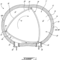
Fig. 1 is a schematic cross-sectional view of a rotary internal combustion engine in accordance with one embodiment; -
Fig. 2 is a schematic fragmented top view of a side wall of a housing of the rotary internal combustion engine ofFig. 1 ; -
Fig. 3 is a schematic fragmented three-dimensional view of the side wall ofFig. 2 ; -
Fig. 4 is a schematic cross-sectional view taken along line B-B ofFig. 2 in accordance with one embodiment; -
Fig. 5 is a schematic cross-sectional view taken along line A-A ofFig. 2 in accordance with the embodiment ofFig. 4 ; -
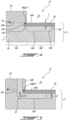
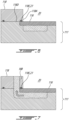
Fig. 6 is a schematic cross-sectional view taken along line B-B ofFig. 2 in accordance with another embodiment; -
Fig. 7 is a schematic cross-sectional view taken along line A-A ofFig. 2 in accordance with the embodiment ofFig. 6 ; -
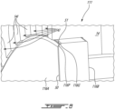
Fig. 8 is a three-dimensional cutaway view of a portion of a side housing in accordance with one embodiment; -
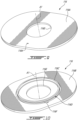
Fig. 9 is a three dimensional view illustrating a rotor-engaging face of a side plate for the side housing ofFig. 8 ; -
Fig. 10 is a three dimensional view illustrating a back face of the side plate ofFig. 9 ; -
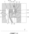
Fig. 11 is a cross-sectional view illustrating the side housing ofFig. 8 and a portion of a rotor housing; -
Fig. 12 is an enlarged view of a portion ofFig. 11 ; -
Fig. 13 is a three dimensional view of a nut used to secure the side plate to the side wall of the side housing ofFig. 8 ; -
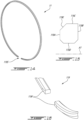
Fig. 14 is a three dimensional view of a retaining ring to secure the side plate to the nut ofFig. 13 ; -
Fig. 15 is a cross-sectional view of the retaining ring ofFig. 14 ; -
Fig. 16 is a three dimensional view of a portion of the retaining ring ofFig. 14 ; -
Fig. 17 is a three dimensional view of a tool for engaging the nut ofFig. 13 ; and -
Figs. 18-19 are cutaway views of the side housing ofFig. 8 and the tool ofFig. 17 illustrating an assembly process of the side plate to the side wall. - Referring to
Fig. 1 , a rotary internal combustion engine, referred to simply as arotary engine 10 below, which may be a Wankel engine, is schematically shown. Therotary engine 10 comprises anouter body 12, also referred to as a housing assembly since it includes a plurality of housings mounted to one another. Theouter body 12 has axially-spacedside housings 11, which each includes aside wall 14 and aside plate 16 mounted to theside wall 14, with aperipheral wall 18 extending from one of the side housings 11 to the other, to form arotor cavity 20. InFig. 1 , theside wall 14 is indicated with a dashed line because it sits behind theside plate 16. The inner surface of theperipheral wall 18 of thecavity 20 has a profile defining two lobes, which may be an epitrochoid. - The
outer body 12 includes acoolant circuitry 12A, which may include a plurality ofcoolant conduits 18B defined within theperipheral wall 18. As shown more clearly inFig. 5 , thecoolant conduits 18B extends from one of the side housings 11 to the other. Thecoolant circuitry 12A is used for circulating a coolant, such as water or any suitable coolant, to cool theouter body 12 during operation of therotary engine 10. Although only twocoolant conduits 18B are shown, it is understood that more than twocoolant conduits 18B may be used without departing from the scope of the present invention. - An inner body or
rotor 24 is received within therotor cavity 20. Therotor 24 has axially spaced end faces 26 adjacent to theside walls 14, and aperipheral face 28 extending therebetween. Theperipheral face 28 defines three circumferentially-spacedapex portions 30, and a generally triangular profile with outwardlyarched sides 36. Theapex portions 30 are in sealing engagement with the inner surface ofperipheral wall 18 to form threerotating combustion chambers 32 between therotor 24 andouter body 12. The geometrical axis of therotor 24 is offset from and parallel to the axis of theouter body 12. - The
combustion chambers 32 are sealed. In the embodiment shown, eachrotor apex portion 30 has anapex seal 52 extending from oneend face 26 to the other and biased radially outwardly against theperipheral wall 18. An end seal 54 engages each end of eachapex seal 52 and is biased against therespective side wall 14. Each end face 26 of therotor 24 has at least one arc-shapedface seal 60 running from eachapex portion 30 to eachadjacent apex portion 30, adjacent to but inwardly of the rotor periphery throughout its length, in sealing engagement with the end seal 54 adjacent each end thereof and biased into sealing engagement with theadjacent side plates 16 of the side housings 11. Alternate sealing arrangements are also possible. - Although not shown in the Figures, the
rotor 24 is journaled on an eccentric portion of a shaft such that the shaft rotates therotor 24 to perform orbital revolutions within therotor cavity 20. The shaft may rotate three times for each complete rotation of therotor 24 as it moves around therotor cavity 20. Oil seals are provided around the eccentric to impede leakage flow of lubricating oil radially outwardly thereof between the respectiverotor end face 26 and side housings 11. During each rotation of therotor 24, eachchamber 32 varies in volumes and moves around therotor cavity 20 to undergo the four phases of intake, compression, expansion and exhaust, these phases being similar to the strokes in a reciprocating-type internal combustion engine having a four-stroke cycle. - The engine includes a
primary inlet port 40 in communication with a source of air and anexhaust port 44 In the embodiment shown, theports peripheral wall 18. Alternate configurations are possible. - In a particular embodiment, fuel such as kerosene (jet fuel) or other suitable fuel is delivered into the
chamber 32 through a fuel port (not shown) such that thechamber 32 is stratified with a rich fuel-air mixture near the ignition source and a leaner mixture elsewhere, and the fuel-air mixture may be ignited within the housing using any suitable ignition system known in the art (e.g. spark plug, glow plug). In a particular embodiment, therotary engine 10 operates under the principle of the Miller or Atkinson cycle, with its compression ratio lower than its expansion ratio, through appropriate relative location of theprimary inlet port 40 andexhaust port 44. - Referring now to
Figs. 2-5 , one of twoside housings 11 of theouter body 12 is illustrated. As briefly introduced above, theside housings 11 include theside walls 14 that are secured to theperipheral wall 18. Each of theside walls 14 has a portion located proximate an outer perimeter P (Fig. 4 ) of theside wall 14 and configured to be in abutment against theperipheral wall 18 for defining therotor cavity 20. - In the embodiment shown, each of the
side walls 14 is configured to be secured to a respective one of opposed ends of theperipheral wall 18. The side housings 11 further includeside plates 16 located on inner sides of theside walls 14. Theside plates 16 define rotor-engagingfaces 16A on which the side seals 60 and the corner seals 54 of therotor 24 are in abutment during rotation of therotor 24. Theside plates 16 further define back faces opposite the rotor-engagingfaces 16A. The back faces of theside plates 16 face theside walls 14. - The
side walls 14 may be made of aluminum, more specifically an aluminum alloy, due to its light weight and high thermal conductivity. However, it may be required that the surfaces of theside walls 14 in contact with theseals 54, 60 be coated to provide a wear-resistance surface. In the embodiment shown, theside plates 16 are made of aluminum and coated with a hard material such as silicon carbide, aluminum nitride, chromium carbide, tungsten carbide, and so on. Any suitable wear resistant coating applied by thermal spray or any other suitable method may be used. Theside walls 14 and theside plates 16 will be described in more details below. Although the text below uses the singular form, the description may be applied to both of theside walls 14 and to both of theside plates 16. - It will be appreciated that, in some embodiments, the rotary engine may include more than one rotor. In such a case, the
outer body 12 includes twoside housings 11 and one or more intermediate housing(s) disposed between the twoside housings 11. Each of the one or more intermediate housing may include an intermediate wall and two intermediate plates disposed on opposite sides of the intermediate wall. The two intermediate plates, as for the side plates, define the running face against which therotor 24 rides during use. The intermediate housing thus defines running faces for both rotors. Thus, the description below, which focuses on the side wall and the side plate, may also apply to the intermediate wall and intermediate plates. Hence, the principle of the present invention applies to both the side housing and the intermediate housing. - Referring more particularly to
Fig. 4 , theside wall 14 includes aperipheral section 14A, which is in abutment with theperipheral wall 18, and acenter section 14B, which is circumferentially surrounded by theperipheral section 14A. In the disclosed embodiment, theperipheral section 14A of theside wall 14 is secured to theperipheral wall 18. Thecenter section 14B of one of theside walls 14 faces thecenter section 14B of the other of theside walls 14. Theside walls 14 are secured to theperipheral wall 18 with any suitable means known in the art. As shown, a sealingmember 19 is located between theperipheral wall 18 and theperipheral sections 14A of theside walls 14 for limiting coolant from leaking out. The sealingmember 19 may be a O-ring. The sealingmember 19 may be received within an annular recess, which may be defined by one or more of theperipheral wall 18 and theside wall 14. - The
side wall 14 defines arecess 14C for receiving theside plate 16. Theperipheral section 14A of theside wall 14 extends from the outer perimeter P to therecess 14C. As shown, a surface 14D of theperipheral section 14A of theside wall 14 that faces theperipheral wall 18 is axially offset from asurface 14E of thecenter section 14B of theside wall 14. A magnitude of the offset corresponds to a depth of therecess 14C and may correspond to a thickness t of theside plate 16 plus any axial gap defined between a rotor-engaging face of theside plate 16 and theperipheral wall 18. Theside plate 16 is therefore in abutment with thesurface 14E of thecenter section 14B of theside wall 14. In other words, a sealing surface of theside plate 16, located on a side of theside plate 16 that faces the rotor cavity, may be aligned with theperipheral section 14A of theside wall 14. - The
side wall 14 defines anabutment surface 14F. Theabutment surface 14F is defined by a shoulder created by the offset of thesurfaces 14D, 14E of the peripheral andcentral sections side wall 14. Theside wall 14, via itsabutment surface 14F, limits radial movements of theside plate 16 relative to the axis of rotation of therotor 24. - In a particular embodiment, a gap may remain between a peripheral section of the
side plate 16 and theabutment surface 14F of theside wall 14. In other words, and in the embodiment shown, theside plate 16 may be spaced apart from theabutment surface 14F. A size of the gap may change during operation of therotary engine 10 as theside wall 14 and theside plate 16 may expand at different rates with an increase of a temperature in therotor cavity 20. In other words, the space between theside plate 16 and theabutment surface 14F of theside wall 14 may allow relative thermal expansion between theside plate 16 and theside wall 14 so that thermal stress transferred from theside plate 16 to theperipheral wall 18 and theside wall 14 might be minimized. - To limit axial movements of the
side plate 16 relative to the axis of rotation of the rotor 24 (Fig. 1 ), a periphery of theside plate 16 is contained axially between theperipheral wall 18 and theside wall 14. In other words, the periphery of theside plate 16 is sandwiched between theside wall 14 and theperipheral wall 18. A sealingmember 21 is located at the periphery of theside plate 16 for limiting the combustion gases to leak out of therotor cavity 20 and for limiting the cooling fluid from leaking into the combustion chamber 32 (Fig. 1 ). As shown more specifically inFigs. 4-5 , the sealingmember 21 is contained within arecess 16B defined by theside plate 16. The sealingmember 21 may be an O-ring. Any suitable sealing member may be used. - In a particular embodiment, the sealing
member 21 and theabutment surface 14F of theside wall 14 allows theside plate 16 to move radially relative to the side wall. Such a movement, along a radial direction relative to the axis of rotation of therotor 24, may be required in a configuration in which theside wall 14 is made of a material having a coefficient of thermal expansion different than that of theside plate 16 and/or because the different components may be exposed to different temperatures and, thus may exhibit different thermal expansions. - The
side wall 14 further defines apocket 14G that may circumferentially extend a full circumference of theside wall 14. In other words, thepocket 14G is annular. More than one pocket may be used. Thepocket 14G may not cover an entirety of thecenter section 14B of theside wall 14. Thepocket 14G is configured for circulating a liquid coolant, such as water for cooling theside plate 16. Thepocket 14G may be part of thecoolant circuitry 12A and is in fluid flow communication with thecoolant conduits 18B that are defined in theperipheral wall 18. Thepocket 14G extends from thesurface 14E of thecenter section 14B and away from therotor cavity 20. A depth D (Fig. 5 ) of thepocket 14G is defined by a distance along the axis of rotation of therotor 24 between thesurface 14E of thecenter section 14B and abottom surface 14H of thepocket 14G. - As shown in
Figs. 2-3 , theperipheral section 14A of theside wall 14 defines a plurality of ribs 14I that are circumferentially distributed around the rotor cavity. The ribs 14I defines theabutment surface 14F and a portion of thesurface 14E of thecenter section 14B of theside wall 14. Consequently, and in the depicted embodiment, theabutment surface 14F is defined by a plurality of surfaces defined by the ribs 14I. The ribs 14I may be configured to support a pressure load imparted by a combustion of a mixture of air and fuel within thecombustion chambers 32. - Cavities or
spaces 14J are defined between the ribs 14I. More specifically, each pair of two consecutive ones of the ribs 14I defines aspace 14J therebetween. Thespaces 14J are in fluid communication with thepocket 14G and with thecoolant conduits 18B of theperipheral wall 18. Stated otherwise, thecoolant conduits 18B are in fluid communication with thepocket 14G via thespaces 14J between the ribs 14I. Thespaces 14J may allow the liquid coolant to flow from thepocket 14G to thecoolant conduits 18B of theperipheral wall 18. It is understood that the liquid coolant may be circulated in closed loop and through a heat exchanger. The heat exchanger may be used to dissipate heat to an environment outside the engine; the heat transferred from the engine to the liquid coolant. - As shown in
Figs. 2 and5 , a flow F1 of the liquid coolant circulates within thepocket 14G. The flow F1 is divided in sub-flows F2; each of the sub-flows F2 circulating within a respective one of thespaces 14J and within a respective one of thecoolant conduits 18B of thecoolant circuitry 12A. The liquid coolant may be circulated out of theouter body 12 and within a heat exchanger for extracting the heat. The liquid coolant may then be reinjected in thecoolant circuitry 12A for further heat extraction. - Referring now to
Figs. 6-7 , another embodiment of the outer body is generally shown. For the sake of conciseness, only elements that differ from theouter body 12 ofFigs. 2-5 are described. In the embodiment shown, therecess 118C that receives the sealingmember 21 is defined by theperipheral wall 118 instead of by theside plate 116. - Referring to
Fig. 8 , as mentioned above, theside plate 116 may be made of aluminum and is coated with a hard material such as silicon carbide or another suitable material such as chromium carbide. The coating of theside plate 116 defines the rotor-engagingface 116A on a rotor-engaging side of theside plate 116. The coating may be applied with plasma spray, high velocity oxygen fuel (HVOF), or any other suitable coating technique. The rotor-engagingface 116A may be enhanced by other techniques such as electro deposited plating (e.g., nanocrystalline CoP, Nickasil) and conversion coatings (e.g., silicon saturation). In the embodiment shown, theside plate 116 has a flaredportion 116P that flares away from anend face 118D (Fig. 6 ) of theperipheral wall 118. The flaredportion 116P extends away from a plane containing a remainder of theside plate 116. The flaredportion 116P extends toward theside wall 14. The flaredportion 116P is shown as being a chamfer, but may alternatively be a round over or any other suitable shape. Afirst coating 50 is deposited on theside plate 116. Thefirst coating 50 extends up to acoating edge 51. Thecoating edge 51 is located on the flaredportion 116P. Therefore, a gap or spacing is provided between thecoating edge 51 and theend face 118D of theperipheral wall 118 such that thecoating edge 51 is distanced from theend face 118D of theperipheral wall 118 by the spacing. Thecoating edge 51 is therefore free of contact with theend face 118D of theperipheral wall 118. Thefirst coating 50 may have a substantially uniform thickness up to thecoating edge 51. Or, in the alternative, thefirst coating 50 may tapers down toward thecoating edge 51. It may tapers down to zero in thickness. In other words, the thickness of thefirst coating 50 may decrease toward thecoating edge 51. The thickness may decrease below its nominal thickness where it covers the flaredportion 116P. Thefirst coating 50 therefore follows the shape of the flaredportion 116P. - The flared
portion 116P may have a first edge and a second edge located outwardly of the first edge relative to the rotation axis of therotor 24. The first edge is located inwardly of aninner face 118A (Fig. 6 ) of theperipheral wall 118. The first edge is thus overlapped by theend face 118D of theperipheral wall 118. The first edge is located between theinner face 118A of theperipheral wall 118 and an outer face of theperipheral wall 118; the outer face facing away from therotor cavity 20. Therefore, a start location of the flaredportion 116P, which corresponds to the first edge, is aligned with, or is overlapped by, theperipheral wall 118 and may be offset from a coating deposited on theinner face 118A of theperipheral wall 118. Thus, thefirst coating 50, located on the flaredportion 116P, may be free of contact with the coating 70 of theperipheral wall 118. More detail about this coating arrangement is provided inU.S. Patent No.: 11,333,068 - In the embodiment shown, the
coating edge 51 ends at aperipheral groove 116G. A radial gap is therefore present between theside plate 116 and theabutment surface 14F of theside wall 14 at theperipheral groove 116G. The side plate outer edge geometry may alternatively include only of a simple chamfer or radius. - In some cases, the side plate may be in intimate contact with the peripheral face. Thus, when the engine stack is clamped during assembly some preload may be transferred to the coating surface. During engine operation, additional loads may be imposed to the side plate and relative slip between the mating parts may occur. After some engine running time, the coating edge area on the side plate may be progressively worn by the coating on the peripheral wall. This may initiate coating cracks and eventually coating edge spalling on the side plate. Moreover, a relatively high internal oil consumption may be exhibited due to difficulty of controlling deformations of the side plate during operation. The side plate may be fixed on the side housing with several small bolts pulling near the central portion and potentially creating local depressions on the final coated surface located on the other side of the side plate, and therefore further increasing the oil consumption because of the difficulty of the rotor side sealing grid to follow this locally deformed surface closely enough to avoid oil leaks. Also, the side plate is put in sandwich between the side wall and the peripheral wall. This creates two highly loaded axial interfaces on both sides of the side plate and may present potential areas of concern for surface fretting damage. Also, on the engine level, introducing several components in the axial stack increases the variability in positioning the bearing centers. The part geometry may be complicated at least part due to cooling passages that may be machined in the side plate to allow coolant to flow from the side wall to the peripheral wall. Fitting all these features on the side plate may limit the available design space and drives thin wall thickness at many locations. These locations may become stress risers and become potential weaker point for the part resistance to fatigue damage. Moreover, care should be taken when securing the side plate to prevent blocking oil passages.
- Referring now to
Fig. 9-11 , features of aside plate 116 of the present invention may at least partially alleviate these drawbacks. Theside plate 116 has a rotor-engaging side that defines a rotor-engagingface 116A facing therotor cavity 20 and in contact with therotor 24, and a back side that defines aback face 116B opposed to the rotor-engagingface 116A. Theback face 116B faces away from therotor cavity 20 and away from therotor 24. Theback face 116B faces theside wall 14 and may be in contact with theside wall 14. The back side of theside plate 116 defines aprotrusion 116C that extends from theback face 116B and that extends away from theback face 116B and away from the rotor-engagingface 116A. In the present embodiment, and as will be explained later, theside plate 116 is secured to theside wall 14 via theprotrusion 116C. Theside plate 116 is non-rotatable relative to theside wall 14. Theprotrusion 116C and theside plate 116 may be two parts of a single monolithic body. In other words, theprotrusion 116C may monolithically protrude from theback face 116B. - The
protrusion 116C defines aprotrusion groove 116D, which is herein located on a face of theprotrusion 116C that faces a radially-outward direction. Theprotrusion 116C is circular and extends circumferentially a full circumference around an axis A1, which may be a central axis of theside wall 14 or of theside plate 116. This axis A1 may correspond to a rotation axis of a crank shaft of therotary engine 10; the crank shaft engaged by the rotor. In an alternate embodiment, theprotrusion 116C may include a plurality of protrusion segments circumferentially distributed about the axis A1. The segments may be spaced apart from one another. Theside plate 116 defines acentral hole 116E located inwardly of theprotrusion 116C. Thecentral hole 116E is surrounded by theprotrusion 116C. Theside plate 116 further defines agroove 116F extending from theback face 116B towards the rotor-engagingface 116A. Thegroove 116F is located radially outwardly of theprotrusion 116C. Thegroove 116F thus extends around theprotrusion 116C. - Referring now to
Figs. 11-13 , in the embodiment shown, theside wall 14 defineswall threads 14K located within asecond recess 14L. Thesecond recess 14L extends from therecess 14C away from theside plate 116. Thewall threads 14K are thus defined by a radially-inner face that extends around the axis A1 and around thesecond recess 14L. Thewall threads 14K may therefore be inner threads since they face the axis A1. - The
side housing 111 further includes anut 117, which may also be referred to as a fastening member, used for securing theside plate 116 to theside wall 14. Thenut 117 is rotatable about the axis A1. Thenut 117 includes aweb 117A and aflange 117B protruding axially from a radially-outer end of theweb 117A. Theflange 117B definesnut threads 117C located on a radially-outwardly facing face of theflange 117B. Thenut threads 117C may thus be outer threads since they face away from the axis A1. Thenut 117 is removably securable to theside wall 14 via a threading engagement of thewall threads 14K to thenut threads 117C. As shown inFig. 12 , theflange 117B of thenut 117 defines anut groove 117D located on an opposite face of theflange 117B than thenut threads 117C. Thenut threads 117C and thenut groove 117D may be located on opposite faces of theflange 117B. Thenut groove 117D is axially aligned and is in register with theprotrusion groove 116D. To this end, theprotrusion 116C of theside plate 116 and theflange 117B of thenut 117 axially overlap one another. A portion of theflange 117B of thenut 117 is received within thegroove 116F of theside plate 116. Thus, thegroove 116F may allow to minimize an axial length of theflange 117B of thenut 117. However, in some embodiments, thegroove 116F may be omitted. - As shown in
Fig. 13 , thenut 117 extends from a radially-inner face 117E defined by theweb 117A and oriented towards the axis A1 to a radially-outer face 117F defined by theflange 117B and oriented away from the axis A1. As more clearly visible onFig. 11 , the radially-inner face 117E of thenut 117 is located radially inwardly of thecentral hole 116E of theside plate 116. The radially-inner face 117E defining torqueing faces 117G sized to be engaged by a tool for rotating the nut about the axis A1. In one embodiment, the torqueing faces 117G include twelve torqueing faces circumferentially distributed about the axis A1 and configured to be engaged by a tool defining also twelve faces. Any number of torqueing faces is contemplated. Alternatively, thenut 117 may define teeth/grooves at its inner diameter to be engaged by a correspondingly-shaped tool. Any suitable features may be provided on thenut 117 to permit its engagement by a tool to induce its rotation relative to theside plate 116. - The
nut 117 may includeinserts 117H extending through theflange 117B. Theinserts 117H may be made of nylon or any suitable material. Theinserts 117H may be deformed by the wall threads 14Kand may provide frictional resistance against rotation to prevent thenut 117 from becoming loose over time. Any other suitable anti-rotation features may be used such as spiralock™ or any suitable locking threads for instance. Theinserts 117H may include only one insert or more than one insert distributed around the central axis A1. Thenut 117 may define apertures 117I extending radially through theflange 117B and communicating with thenut groove 117D. These apertures 117I may be sized to receive a tool used to push on a retaining ring to remove the retaining ring from thenut groove 117D by pushing on the retaining ring outer diameter in order to temporally compress its diameter and permit the disengagement of thenut 117 from theside plate 16. The retaining ring is further described below. - As depicted in
Fig. 12 , thenut 117 and theside plate 116 are axially locked to one another while being rotatable one relative to the other about the axis A1. In the embodiment illustrated, a retainingring 119 is used to axially lock thenut 117 to theside plate 116. In other words, a locking engagement is provided between theside plate 116 and thenut 117. It will be appreciated that any suitable retaining means may be used to axially lock theside plate 116 to thenut 117 while permitting rotation of thenut 117 about the axis A1 and relative to theside plate 116. For instance, a dog and slot arrangement may be possible, a tongue and groove, a keyway, and so on. Hence, the retainingring 119 may be omitted in some embodiments. - In the embodiment shown, the
side plate 116 is secured to theside wall 14 via thenut 117. Put differently, theside plate 116 is secured to theside wall 14 via a threading engagement between thenut threads 117C of thenut 117 and thewall threads 14K of theside wall 14 and via the retaining means. More specifically, in the exemplified embodiment, the retainingring 119 is received conjointly within thenut groove 117D of thenut 117 and theprotrusion groove 116D of theprotrusion 116C of theside plate 116. The retainingring 119 is thus in abutment against faces surrounding thenut groove 117D and theprotrusion groove 116D such that any axial force exerted to separate theside plate 116 from thenut 117 is opposed by the retainingring 119 abutting the faces bounding thenut groove 117D and theprotrusion groove 116D. - It will be appreciated that, in some embodiments, the
protrusion 116C of theside plate 116 may be omitted and that features of the protrusion described above may be provided within a circumferential recess extending from theback face 116B to the rotor-engagingface 116A of theside plate 116. - Still referring to
Fig. 12 , in the depicted embodiment, a sealingmember 120 is received within awall groove 14M defined by theside wall 14. Thewall groove 14M may be alternatively defined by theside plate 116 or conjointly by the side wall and the side plate. The sealingmember 120 is located radially-outwardly of thewall threads 14K of theside wall 14 and is in abutment against theback face 116B of theside plate 116. The sealingmember 120 is thus compressed between theside wall 14 and theside plate 116. By disposing the sealingmember 120 radially-outwardly of thewall threads 14K as shown, axial space savings may be obtained. - A depth of the
second recess 14L taken in an axial direction relative to the axis A1 is greater than an axial width W1 of thenut 117. This creates an annular space S located axially between a bottom of thesecond recess 14L and thenut 117. This annular space S is devoid of thenut 117 and permits a flow F1 of lubricant to reachlubricant passages 14N of theside wall 14. Thenut 117 thus may not obstruct thelubricant passages 14N. - Referring to
Figs. 14-16 , the retainingring 119 is described in greater detail. The retainingring 119 is radially deformable. This allows the retainingring 119 to be disposed within theprotrusion groove 116D of theprotrusion 116C of theside plate 116. In this embodiment, the retainingring 119 defines a slit 119S permitting its radial deformation. The retainingring 119 may thus be partially annular since the slit 119S is free of the retainingring 119. An at-rest shape of the retainingring 119 is shown inFig. 12 and defines a diameter in which theretaining ring 119 is partially received within both of theprotrusion groove 116D and thenut groove 117D. - As shown in
Fig. 15 , the retainingring 119 has a firstaxial face 119A, a secondaxial face 119B opposed to the firstaxial face 119A, an outerradial face 119C oriented away from the axis A1, and an innerradial face 119D opposed to the outerradial face 119C and oriented towards the axis A1. As shown inFig. 11 , the firstaxial face 119A is oriented towards theside wall 14 whereas the secondaxial face 119B is oriented towards theside plate 116. In the illustrated embodiment, achamfer 119E is provided at an intersection between the firstaxial face 119A and the outerradial face 119C. Thechamfer 119E may be used to facilitate an assembly of thenut 117 to theside plate 116. More specifically, thechamfer 119E is located to abut theflange 117B of thenut 117, which may itself be provided with a chamfer, such that when moving thenut 117 and theside plate 116 axially one relative to the other, theflange 117B of thenut 117 abuts thechamfer 119E thereby pushing the retainingring 119 radially inwardly towards the axis A1 and deeper into theprotrusion groove 116D until the retainingring 119 is axially aligned with thenut groove 117D. At which point, the retainingring 119 is able to expand radially outwardly and snaps into place where it sits into thenut groove 117D. The retainingring 119 is thus received conjointly in both thenut groove 117D and theprotrusion groove 116D of theside plate 116 thereby axially locking theside plate 116 to thenut 117 while permitting rotation of thenut 117 relative to theside plate 116. Thechamfer 119E may be omitted in some embodiments. - As shown in
Fig. 16 , the retainingring 119 defines twotapers 119F located on opposite sides of the slits 119S. Thesetapers 119F are created by one of the firstaxial face 119A and the secondaxial face 119B extending towards the other of the firstaxial face 119A and the secondaxial face 119B and towards the slit 119S. The tapers may be defined by both axial faces. Thesetapers 119F may prevent theretaining ring 119 from biting into theprotrusion 116C of theside plate 116 when rotating thenut 117 relative to theside plate 116. - Referring now to
Fig. 17 , atool 200 to be used to rotate thenut 117 is shown. Thetool 200 includes acylindrical wall 201 extending around a tool axis A2. A web 202 (Fig. 19 ) is secured to thecylindrical wall 201 and extends transversally to the tool axis A2. Ahead 203 is secured to theweb 202. Thehead 203 defines an hexagonal shape to be engaged by a wrench or any suitable tool. Other shapes of the head 2023 are contemplated. Thecylindrical wall 201 defines torqueing faces 204 sized to engage the torqueing faces 117G (Fig. 13 ) of thenut 117. Astopper 205, provided in the form of an annular wall, is secured to thecylindrical wall 201 between the torqueing faces 117G and theweb 202. - To assemble the
side plate 116 to theside wall 14, the retainingring 119 may be expanded to be disposed around theprotrusion 116C of theside plate 116 until it registers with theprotrusion groove 116D of theside plate 116. The retainingring 119 may thus contract into theprotrusion groove 116D. At which point, theside plate 116 and thenut 117 may be moved axially one towards the other until the retainingring 119 abuts theflange 117B of thenut 117 thereby pushing against the retainingring 119 to contract it radially inwardly into theprotrusion groove 116D until the retainingring 119 becomes in register with thenut groove 117D and snaps into thenut groove 117D. - As shown in
Figs. 18-19 , to fasten thenut 117 and theside plate 116 to theside wall 14, thetool 200 is inserted into thecentral hole 116E of theside plate 116 until the torqueing faces 204 of thetool 200 engage the torqueing faces 117G of thenut 117. Aprotective sleeve 206 may be disposed axially between theside plate 116 and thestopper 205. Theprotective sleeve 206 may be used to protect the rotor-engagingface 116A of theside plate 116 from thetool 200. At which point, theside plate 116 may be moved into therecess 14C until thewall threads 14K and thenut threads 117C abut one another. Then, thetool 200 may be used to rotate thenut 117 relative to theside plate 116 thereby threadingly engaging the wall threads 14Kto thenut threads 117C until theside plate 116 is seated inside therecess 14C as shown inFig. 19 . At which point, thetool 200 may be removed. A clamping force exerted on theside plate 116 may be controlled via a torque applied on thetool 200. - A ratio of a thread diameter of the
wall threads 14K of theside wall 14 to a diameter of the sealingmember 120 may range from 0.96 to 0.98, preferably about 0.98; a ratio of the thread diameter of thewall threads 14K to a diameter of thecentral hole 116E of theside plate 116 may range from 1.5 to 1.75, preferably about 1.7; a ratio of the thread diameter of thewall threads 14K to a diameter of thenut 117 at the radially-inner face 117E may range from 1.5 to 1.89, preferably about 1.78. A ratio of the thread diameter of thewall threads 14K to a diameter of a location of a pressure relieve aperture (not shown), also referred to as a blow-by hole, may range from 0.83 to 0.92, preferably 0.873. A thickness ratio between outer and inner portions of theside plate 116 may range from 1.3 to 1.9 preferably 1.62. A shape of the pressure relieve aperture may be racetrack nominal diameter of. 0.081 inch to 0.246 inch. The inner and outer portions of theside plate 116 are in relation to the protrusion; the inner and outer portions are respectively located radially inwardly and outwardly of the protrusion. - In the context of the present disclosure, the expression "about" implies variations of plus or minus 10%.
- It is noted that various connections are set forth between elements in the preceding description and in the drawings. It is noted that these connections are general and, unless specified otherwise, may be direct or indirect and that this specification is not intended to be limiting in this respect. A coupling between two or more entities may refer to a direct connection or an indirect connection. An indirect connection may incorporate one or more intervening entities. The term "connected" or "coupled to" may therefore include both direct coupling (in which two elements that are coupled to each other contact each other) and indirect coupling (in which at least one additional element is located between the two elements).
- It is further noted that various method or process steps for embodiments of the present invention are described in the following description and drawings. The description may present the method and/or process steps as a particular sequence. However, to the extent that the method or process does not rely on the particular order of steps set forth herein, the method or process should not be limited to the particular sequence of steps described. As one of ordinary skill in the art would appreciate, other sequences of steps may be possible. Therefore, the particular order of the steps set forth in the description should not be construed as a limitation.
- Furthermore, no element, component, or method step in the present disclosure is intended to be dedicated to the public regardless of whether the element, component, or method step is explicitly recited in the claims. As used herein, the terms "comprises", "comprising", or any other variation thereof, are intended to cover a non-exclusive inclusion, such that a process, method, article, or apparatus that comprises a list of elements does not include only those elements but may include other elements not expressly listed or inherent to such process, method, article, or apparatus.
- While various aspects of the present invention have been disclosed, it will be apparent to those of ordinary skill in the art that many more embodiments and implementations are possible within the scope of the claims. For example, the present invention as described herein includes several aspects and embodiments that include particular features. Although these particular features may be described individually, it is within the scope of the claims that some or all of these features may be combined with any one of the aspects and remain within the scope of the claims. References to "various embodiments," "one embodiment," "an embodiment," "an example embodiment," etc., indicate that the embodiment described may include a particular feature, structure, or characteristic, but every embodiment may not necessarily include the particular feature, structure, or characteristic. Moreover, such phrases are not necessarily referring to the same embodiment. The use of the indefinite article "a" as used herein with reference to a particular element is intended to encompass "one or more" such elements, and similarly the use of the definite article "the" in reference to a particular element is not intended to exclude the possibility that multiple of such elements may be present.
- The embodiments described in this document provide non-limiting examples of possible implementations of the present technology. Upon review of the present disclosure, a person of ordinary skill in the art will recognize that changes may be made to the embodiments described herein without departing from the scope of the claims. Yet further modifications could be implemented by a person of ordinary skill in the art in view of the present disclosure, which modifications would be within the scope of the claims.
Claims (12)
- A side housing (11; 111) for a rotary internal combustion engine, the side housing (11, 111) comprising:a side wall (14) defining first threads (14K), the first threads (14K) extending around a central axis (A1);a side plate (16; 116) having a rotor-engaging side facing away from the side wall (14) and a back side opposite the rotor-engaging side and facing the side wall (14); anda nut (117) rotatable relative to the side plate (16; 116) about the central axis (A1), wherein the nut (117) and the side plate (16; 116) are axially locked to one another, the nut (117) defines second threads (117C) extending around the central axis (A1), and the side plate (16; 116) is secured to the side wall (14) via a threading engagement between the first threads (14K) of the side wall (14) and the second threads (117C) of the nut (117).
- The side housing (111) of claim 1, wherein the nut (117) has a radially-innerface (117E) oriented towards the central axis (A1) and a radially-outer face (117F) oriented away from the central axis (A1), the radially-outer face (117F) defines the second threads (117C), the radially-inner face (117E) is located radially inwardly of a central hole (116E) of the side plate (16; 116), and the radially-inner face (117E) defines torqueing faces (117G) configured to be engaged by a tool (200) for rotating the nut (117) about the central axis (A1).
- The side housing (111) of claim 1 or 2, wherein the nut (117) and the side plate (16; 116) are axially locked to one another via a retaining ring (119).
- The side housing (111) of claim 3, wherein the retaining ring (119) defines a first axial face (119A) oriented towards the side wall (14), a second axial face (119B) oriented towards the side plate (16; 116), an inner face (119D) oriented towards the central axis (A1), an outer face (119C) oriented away from the central axis (A1), and a chamfer (119E) at an intersection between the first axial face (119A) and the outer face (119C).
- The side housing (111) of claim 3 or 4, wherein the side plate (16; 116) defines a protrusion (116C) extending from a back face (116B) of the side plate (16; 116), the nut (117) has a web (117A) and a flange (117B) extending axially from the web (117A), the flange (117B) and the protrusion (116C) axially overlap one another, and the retaining ring (119) is disposed radially between the protrusion (116C) and the flange (117B).
- The side housing (111) of claim 5, wherein a portion of the flange (117B) of the nut (117) is received within a groove (116F) defined by the side plate (16; 116).
- The side housing (111) of claim 5 or 6, wherein the nut (117) defines a nut groove (117D) at the flange (117B), the protrusion (116C) defines a protrusion groove (116D), and the retaining ring (119) is received conjointly within both of the protrusion groove (116D) and the nut groove (117D).
- The side housing (111) of claim 5, 6 or 7, wherein the protrusion (116C) is monolithic with a remainder of the side plate (16; 116).
- The side housing (111) of any of the preceding claims, wherein the side wall (14) defines a recess (14L) surrounded by a radially-inner face oriented towards the central axis (A1), the radially-inner face defines the first threads (14K), the nut (117) is received within the recess (14L), the nut (117) has a or the radially-outer face (117F) oriented away from the central axis (A1), and the second threads (117C) are defined by the radially-outer face (117F).
- The side housing (111) of claim 9, wherein a depth of the recess (14L) is greater than an axial width (W1) of the nut (117), and an annular space (S) is located between a face of the recess (14L) and the nut (117).
- The side housing (111) of any of the preceding claims, comprising a sealing member (21) received within a groove (16B) defined by the side plate (16; 116) and/or the side wall (14), wherein the sealing member (21) is located radially-outwardly of the first threads (14K) and of the second threads (117C) and compressed between the side plate (16; 116) and the side wall (14).
- A rotary internal combustion engine comprising:a rotor (24);an outer body (12) circumscribing a rotor cavity (20), wherein the rotor (24) is received within the rotor cavity (20) and rotatable within the rotor cavity (20) relative to the outer body (12), the outer body (12) has a rotor housing (18) extending around a central axis (A1), side housings (11; 111) are mounted to the rotor housing (18), the rotor cavity (20) extends axially between the side housings (11; 111), and the side housings (11; 111) include a side housing (11; 111) according to any preceding claim.
Applications Claiming Priority (1)
| Application Number | Priority Date | Filing Date | Title |
|---|---|---|---|
| US18/470,791 US12110819B1 (en) | 2023-09-20 | 2023-09-20 | Side plate for rotary engine |
Publications (1)
| Publication Number | Publication Date |
|---|---|
| EP4528075A1 true EP4528075A1 (en) | 2025-03-26 |
Family
ID=92883554
Family Applications (1)
| Application Number | Title | Priority Date | Filing Date |
|---|---|---|---|
| EP24201486.8A Pending EP4528075A1 (en) | 2023-09-20 | 2024-09-19 | Side plate for rotary engine |
Country Status (3)
| Country | Link |
|---|---|
| US (1) | US12110819B1 (en) |
| EP (1) | EP4528075A1 (en) |
| CA (1) | CA3253461A1 (en) |
Citations (3)
| Publication number | Priority date | Publication date | Assignee | Title |
|---|---|---|---|---|
| CA3060734A1 (en) * | 2018-12-20 | 2020-06-20 | Pratt & Whitney Canada Corp. | Rotary engine with housing having silicon carbide plate |
| US11333068B1 (en) | 2021-03-23 | 2022-05-17 | Pratt & Whitney Canada Corp. | Side wall for rotary engine housing |
| US11761376B1 (en) * | 2022-11-11 | 2023-09-19 | Pratt & Whitney Canada Corp. | Side plate for rotary engine |
Family Cites Families (5)
| Publication number | Priority date | Publication date | Assignee | Title |
|---|---|---|---|---|
| US4741308A (en) | 1986-08-15 | 1988-05-03 | Ballinger Michael S | Rotary internal combustion engine and method of operation |
| FI20050451L (en) * | 2005-04-29 | 2006-10-30 | Sulzer Pumpen Ag | Centrifugal pump side plate mounting sealing arrangement and mounting screw used therein |
| EP2878824B1 (en) * | 2012-05-21 | 2019-08-21 | Nabtesco Automotive Corporation | Vacuum pump |
| GB201313824D0 (en) * | 2013-08-01 | 2013-09-18 | Orbital Power Ltd | A Rotary Engine |
| US10072566B2 (en) | 2015-12-18 | 2018-09-11 | Pratt & Whitney Canada Corp. | Rotary engine casing with seal engaging plate having mating surface defining a fluid cavity |
-
2023
- 2023-09-20 US US18/470,791 patent/US12110819B1/en active Active
-
2024
- 2024-08-27 CA CA3253461A patent/CA3253461A1/en active Pending
- 2024-09-19 EP EP24201486.8A patent/EP4528075A1/en active Pending
Patent Citations (3)
| Publication number | Priority date | Publication date | Assignee | Title |
|---|---|---|---|---|
| CA3060734A1 (en) * | 2018-12-20 | 2020-06-20 | Pratt & Whitney Canada Corp. | Rotary engine with housing having silicon carbide plate |
| US11333068B1 (en) | 2021-03-23 | 2022-05-17 | Pratt & Whitney Canada Corp. | Side wall for rotary engine housing |
| US11761376B1 (en) * | 2022-11-11 | 2023-09-19 | Pratt & Whitney Canada Corp. | Side plate for rotary engine |
Also Published As
| Publication number | Publication date |
|---|---|
| US12110819B1 (en) | 2024-10-08 |
| CA3253461A1 (en) | 2025-06-03 |
Similar Documents
| Publication | Publication Date | Title |
|---|---|---|
| EP4368810B1 (en) | Side plate for rotary engine | |
| EP3670833B1 (en) | Rotary engine with housing having silicon carbide plate | |
| EP2623710B1 (en) | Rotary internal combustion engine with cooled insert | |
| RU2548522C2 (en) | Rotor assy with adjustable vanes with rollers | |
| US9874097B2 (en) | Shroud for rotary engine | |
| US11333068B1 (en) | Side wall for rotary engine housing | |
| EP4063617A1 (en) | Retaining assembly with anti-rotation feature | |
| US20250073859A1 (en) | Socket assembly for engaging a nut | |
| US12110819B1 (en) | Side plate for rotary engine | |
| EP4435229A1 (en) | Rotary engine with seal having elastomeric member and shield | |
| EP4477837A1 (en) | Rotary engine with seal having elastomeric and metallic members | |
| US12435661B1 (en) | Rotary engine with seal having shield and elastomeric member | |
| US12558747B2 (en) | Method of assembling parts with different coefficients of thermal expansion | |
| US12203410B1 (en) | Housing assembly for rotary engine | |
| US12503975B1 (en) | Housing assembly for rotary engine and method of manufacturing thereof | |
| US12291991B1 (en) | Housing assembly for rotary engine |
Legal Events
| Date | Code | Title | Description |
|---|---|---|---|
| PUAI | Public reference made under article 153(3) epc to a published international application that has entered the european phase |
Free format text: ORIGINAL CODE: 0009012 |
|
| STAA | Information on the status of an ep patent application or granted ep patent |
Free format text: STATUS: THE APPLICATION HAS BEEN PUBLISHED |
|
| AK | Designated contracting states |
Kind code of ref document: A1 Designated state(s): AL AT BE BG CH CY CZ DE DK EE ES FI FR GB GR HR HU IE IS IT LI LT LU LV MC ME MK MT NL NO PL PT RO RS SE SI SK SM TR |
|
| STAA | Information on the status of an ep patent application or granted ep patent |
Free format text: STATUS: REQUEST FOR EXAMINATION WAS MADE |
|
| 17P | Request for examination filed |
Effective date: 20250926 |
|
| RIC1 | Information provided on ipc code assigned before grant |
Ipc: F01C 1/22 20060101AFI20260506BHEP Ipc: F01C 21/06 20060101ALI20260506BHEP Ipc: F01C 21/10 20060101ALI20260506BHEP Ipc: F02B 53/00 20060101ALI20260506BHEP Ipc: F02B 55/08 20060101ALI20260506BHEP |
|
| GRAP | Despatch of communication of intention to grant a patent |
Free format text: ORIGINAL CODE: EPIDOSNIGR1 |
|
| STAA | Information on the status of an ep patent application or granted ep patent |
Free format text: STATUS: GRANT OF PATENT IS INTENDED |
|
| INTG | Intention to grant announced |
Effective date: 20260615 |