EP4528070A2 - Optical monitoring of threaded connection make-up and break-out processes - Google Patents
Optical monitoring of threaded connection make-up and break-out processes Download PDFInfo
- Publication number
- EP4528070A2 EP4528070A2 EP25156137.9A EP25156137A EP4528070A2 EP 4528070 A2 EP4528070 A2 EP 4528070A2 EP 25156137 A EP25156137 A EP 25156137A EP 4528070 A2 EP4528070 A2 EP 4528070A2
- Authority
- EP
- European Patent Office
- Prior art keywords
- tubular
- camera
- threading
- rotor
- displacement
- Prior art date
- Legal status (The legal status is an assumption and is not a legal conclusion. Google has not performed a legal analysis and makes no representation as to the accuracy of the status listed.)
- Granted
Links
Images



Classifications
-
- G—PHYSICS
- G06—COMPUTING OR CALCULATING; COUNTING
- G06T—IMAGE DATA PROCESSING OR GENERATION, IN GENERAL
- G06T7/00—Image analysis
- G06T7/20—Analysis of motion
- G06T7/269—Analysis of motion using gradient-based methods
-
- E—FIXED CONSTRUCTIONS
- E21—EARTH OR ROCK DRILLING; MINING
- E21B—EARTH OR ROCK DRILLING; OBTAINING OIL, GAS, WATER, SOLUBLE OR MELTABLE MATERIALS OR A SLURRY OF MINERALS FROM WELLS
- E21B17/00—Drilling rods or pipes; Flexible drill strings; Kellies; Drill collars; Sucker rods; Cables; Casings; Tubings
- E21B17/02—Couplings; joints
- E21B17/04—Couplings; joints between rod or the like and bit or between rod and rod or the like
- E21B17/042—Threaded
-
- E—FIXED CONSTRUCTIONS
- E21—EARTH OR ROCK DRILLING; MINING
- E21B—EARTH OR ROCK DRILLING; OBTAINING OIL, GAS, WATER, SOLUBLE OR MELTABLE MATERIALS OR A SLURRY OF MINERALS FROM WELLS
- E21B19/00—Handling rods, casings, tubes or the like outside the borehole, e.g. in the derrick; Apparatus for feeding the rods or cables
- E21B19/16—Connecting or disconnecting pipe couplings or joints
- E21B19/165—Control or monitoring arrangements therefor
-
- G—PHYSICS
- G06—COMPUTING OR CALCULATING; COUNTING
- G06T—IMAGE DATA PROCESSING OR GENERATION, IN GENERAL
- G06T2207/00—Indexing scheme for image analysis or image enhancement
- G06T2207/10—Image acquisition modality
- G06T2207/10016—Video; Image sequence
Definitions
- This disclosure relates generally to equipment utilized and operations performed in conjunction with a subterranean well and, in an example described below, more particularly provides for optical monitoring of a threaded connection make-up or break-out process.
- Tubulars used in wells can include protective wellbore linings (such as, casing, liner, etc.), production or injection conduits (such as, production tubing, injection tubing, screens, etc.), drill pipe and drill collars, and associated components (such as tubular couplings).
- protective wellbore linings such as, casing, liner, etc.
- production or injection conduits such as, production tubing, injection tubing, screens, etc.
- drill pipe and drill collars such as tubular couplings.
- threaded connections between tubulars it is typically important for threaded connections between tubulars to be properly made-up. For example, when a threaded connection is properly made-up, the threaded connection may prevent leakage of fluid into or out of the tubular string, or may resist unthreading of the connection. When a threaded connection is properly broken-out, the tubulars may be usable in subsequent well operations, such as (but not necessarily) drilling operations.
- a first aspect of the present disclosure is a method of making-up or breaking-out tubular string components for use in a subterranean well, the method comprising:
- the method may further comprise positioning the first camera at the first location, the first camera thereby simultaneously observing at least the first and second tubulars and a threaded third tubular, and in which the second and third tubulars are threaded together prior to the threading.
- the method may further comprise positioning the first camera at the first location, the first camera thereby simultaneously observing at least the first and second tubulars and a rotor.
- the first camera may obtain images of a rotor during the threading.
- the rotor may be a rotor of a rotary clamp.
- the rotor may be a rotor of a top drive.
- the method may further comprise controlling the threading in response to a difference between the first displacement of the first tubular and a third displacement of the rotor, and in which the first and third displacements comprise rotations of the respective first tubular and the rotor.
- the method may further comprise controlling the threading in response to the second displacement of the second tubular being greater than zero, and in which the second displacement comprises a rotation of the second tubular.
- the method may further comprise controlling the threading in response to the first displacement of the first tubular being within a predetermined range, and in which the first displacement comprises a longitudinal displacement of the first tubular.
- the method may further comprise controlling the threading in response to the first displacement of the first tubular being within a predetermined range, and in which the first displacement comprises a rotation of the first tubular.
- the method may further comprise controlling the threading in response to the optical flow vector fields representing a predetermined difference between the first and second displacements.
- the method may further comprise positioning a second camera at a second location, the second camera thereby simultaneously observing a threaded third tubular and at least one of the first and second tubulars; and the optical flow vector fields may represent a third displacement of the third tubular and at least one of the first and second displacements during the threading.
- the method may further comprise positioning a second camera at a second location, the second camera thereby simultaneously observing a rotor and at least one of the first and second tubulars; and the optical flow vector fields may represent a third displacement of the rotor and at least one of the first and second displacements during the threading.
- FIG. 1 Representatively illustrated in FIG. 1 is a system 10 for use with a subterranean well, and an associated method, which can embody principles of this disclosure.
- system 10 and method are merely one example of an application of the principles of this disclosure in practice, and a wide variety of other examples are possible. Therefore, the scope of this disclosure is not limited at all to the details of the system 10 and method described herein and/or depicted in the drawings.
- a tubular string 12 is being assembled and deployed into a well.
- the tubular string 12 in this example is a production or injection tubing string, but in other examples the tubular string could be a casing, liner, drill pipe, completion, stimulation, testing or other type of tubular string.
- the scope of this disclosure is not limited to use of any particular type of tubular string or tubular components connected in a tubular string.
- a tubular 14 is suspended near its upper end by means of a rotary table 16, which may comprise a pipe handling spider and/or safety slips to grip the tubular 14 and support a weight of the tubular string 12.
- a rotary table 16 which may comprise a pipe handling spider and/or safety slips to grip the tubular 14 and support a weight of the tubular string 12.
- the upper end of the tubular 14 extends upwardly through a rig floor 18 in preparation for connecting another tubular 20 to the tubular string 12.
- a tubular coupling 22 is made-up to the upper end of the tubular 14 prior to the tubular being connected in the tubular string 12.
- the coupling 22 is internally threaded in each of its opposite ends.
- a threaded together tubular and coupling In conventional well operations, it is common for a threaded together tubular and coupling to be referred to as a "joint” and for threaded together joints to be referred to as a “stand” of tubing, casing, liner, pipe, etc.
- a separate coupling may not be used; instead one end (typically an upper "box” end of a joint) is internally threaded and the other end (typically a lower "pin” end of the joint) is externally threaded, so that successive joints can be threaded directly to each other.
- the scope of this disclosure can encompass the use of a separate coupling with a tubular, or the use of a tubular without a separate coupling (in which case the coupling can be considered to be integrally formed with, and a part of, the tubular).
- the coupling 22 can also be considered to be a tubular, since it is a tubular component connected in the tubular string 12.
- a set of tongs or rotary and backup clamps 24, 26 are used.
- the rotary clamp 24 in the FIG. 1 example is used to grip, rotate and apply torque to the upper tubular 20 as it is threaded into the coupling 22.
- the backup clamp 26 in the FIG. 1 example is used to grip and secure the lower tubular 14 against rotation, and to react the torque applied by the rotary clamp 24.
- the rotary clamp 24 and the backup clamp 26 may be separate devices, or they may be components of a rig apparatus known to those skilled in the art as an "iron roughneck.”
- the rotary clamp 24 and backup clamp 26 may be components of a tong system, such as the VERO(TM) tong system marketed by Weatherford International, Inc. of Houston, Texas USA.
- the rotary clamp 24 may be a mechanism of the tong system that rotates and applies torque to the upper tubular 20
- the backup clamp 26 may be a backup mechanism of the tong system that reacts the applied torque and prevents rotation of the lower tubular 14.
- rotary clamp indicates the rotation and torque application mechanism
- backup clamp indicates the torque reacting mechanism.
- tubulars 14, 20 and coupling 22, if used
- the tubulars 14, 20 could instead be horizontal or otherwise oriented.
- Additional systems in which the principles of this disclosure may be incorporated include the CAM(TM), COMCAM(TM) and TORKWRENCH(TM) bucking systems marketed by Weatherford International, Inc.
- a top drive (see FIG. 3 ) may be used to rotate and apply torque to the upper tubular 20.
- a top drive may be used to rotate and apply torque to the upper tubular 20.
- the tubular string 12 can be lowered further into the well, and the make-up operation can be repeated to connect another stand to the upper end of the tubular string. In this manner, the tubular string 12 is progressively deployed into the well by connecting successive stands to the upper end of the tubular string.
- an individual tubular component may be added to the tubular string 12, instead of a stand.
- the threaded connection make-up process can be controlled, so that a properly made-up connection is obtained, and this control can be automatic, so that human error is avoided.
- at least one camera 28 can be used in certain examples to facilitate this automatic control of the threaded connection make-up process.
- the term "camera” is used to indicate a device capable of obtaining images of an observed structure.
- Each image can comprise an array or matrix of pixels, with each pixel having a combination of optical characteristics.
- Examples of cameras include digital video cameras, time of flight sensors and optical matrix sensors.
- a camera does not contact a structure observed by the camera.
- FIG. 2A an example of the method of making-up tubular string components is representatively illustrated.
- this example of the method is described below as it may be used with the system 10 of FIG. 1 , but the method may be used with other systems in keeping with the principles of this disclosure.
- the camera 28 observes and obtains images of at least the tubulars 14, 20, the coupling 22 and a rotor 30 of the rotary clamp 24 while the tubular 20 is threaded into the coupling.
- Jaws 32 carried in the rotor 30 grip the tubular 20 in order to apply torque to the tubular 20 as it is threaded into the coupling 22.
- Jaws 34 of the backup clamp 26 grip the tubular 14 in order to react the torque applied by the rotary clamp 24.
- Image data is output from the camera 28. As described more fully below, the image data is input to an image processor 36 (see FIG. 6 ).
- the image processor 36 detects displacements of the various structures observed by the camera 28 using optical flow techniques. These optical flow techniques include grouping optical vector fields representing movements of the various components observed by the camera 28.
- the term "displacement” is used to indicate longitudinal or rotational movement, or a combination of longitudinal and rotational movements (e.g., helical displacement).
- a controller 38 controls the connection make-up process based on these determinations.
- the controller 38 may control operation of the rotary clamp 24 so that a predetermined number of turns of the tubular 20 are accomplished, or so that a total thread loss (e.g., a longitudinal overlap between threaded-together components) is achieved.
- the camera 28 can observe components (such as the tubular 20 and the rotor 30) that displace during the connection make-up process, as well as components (such as the tubular 14 and coupling 22) that should remain stationary during the connection make-up process.
- components such as the tubular 20 and the rotor 30
- components such as the tubular 14 and coupling 22
- slippage between the rotor 30 and the tubular 20 can be detected if there is a difference between rotational displacements of the rotor and the tubular 20.
- slippage between the jaws 34 of the backup clamp 26 and the tubular 14 can be detected if there is rotation of the tubular 14 and the coupling 22 during the connection make-up process.
- Detection of the displacements of the components as discussed above are facilitated by the use of the camera 28 to observe multiple components during the connection make-up process.
- a single camera 28 may observe one, two, three, four, or any other number of components. However, it is not necessary that only a single camera be used to observe all of the components for which it is desired to determine displacements.
- FIG. 2B another example of the method is representatively illustrated.
- multiple cameras 28 are used to observe components of the system 10 during the tubular connection make-up process.
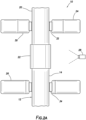
- Each one of the cameras 28 may observe a single component or multiple components. As depicted in FIG. 2B , an upper camera 28 observes the rotor 30 and the tubular 20. A middle camera 28 observes the tubulars 14, 20 and the coupling 22. A lower camera 28 observes the tubular 14 and the backup clamp 26.
- Image data from the multiple cameras 28 can be combined by the image processor 36, so that the movements of all of the components can be determined using the optical flow techniques discussed more fully below. Based on these detected movements, the controller 38 can control the connection make-up process.
- a top drive 40 is used to rotate and apply torque to the tubular 20.
- the backup clamp 26 reacts the torque applied by the top drive 40.
- the camera 28 can observe any, or any combination of, the tubular 20, the coupling 22, the tubular 14 and the backup clamp 26. Multiple cameras 28 may be used if desired.
- the rotor 42 of the top drive 40 is used to rotate and apply torque to the tubular 20.
- the camera 28, or another camera, can observe the rotor 42 and the tubular 20 during the tubular connection make-up process.
- FIG. 4 various components of the system 10 are representatively illustrated as observed by the camera 28 in the example of FIG. 2A .
- Optical vector fields representing detected movements of the components are superimposed on the illustrated components.
- the vector fields result from the optical flow techniques discussed above.
- Rotation of the tubular 20 by the rotor 30 of the rotary clamp 24 is represented by an arrow 44 in FIG. 4 .
- a group of vectors 30a indicate this rotation of the rotor 30 and can be detected by the image processor 36 with appropriate instruction, programming and/or training.
- vectors 20a indicate a similar rotation of the tubular 20.
- the vectors 20a also indicate longitudinal displacement of the tubular 20 as it is threaded into the coupling 22.
- the rotation and longitudinal displacement of the tubular 20, as indicated by the vectors 20a can be detected by the image processor 36 with appropriate instruction, programming and/or training.
- FIG. 4 Although in a normal connection make-up process the tubular 14 and the coupling 22 should not rotate, rotation of these components is depicted in FIG. 4 for convenience in describing a condition that may cause the controller 38 to terminate the connection make-up process.
- a group of vectors 22a indicate rotation of the coupling 22
- a group of vectors 14a indicate rotation of the tubular 14.
- the controller 38 may terminate the connection make-up process (e.g., by ceasing the rotation of the rotor 30) if any of the following conditions is indicated by the optical vector fields:
- the controller 38 may terminate the connection break-out process (e.g., by ceasing the rotation of the rotor 30) if the rotor 30 rotates at a faster rate than the tubular 20, the coupling 22 rotates relative to the tubular 14, or if the tubular 14 rotates.
- the groups of the optical vectors 14a, 20a, 22a, 30a are representatively illustrated apart from the components of the system 10.
- the manner in which the image processor 36 can detect optical vector fields in the image data output by the camera 28 can be more readily visualized.
- optical flow techniques are used to detect the optical vectors 14a, 20a, 22a, 30a represented in the image data.
- the camera 28 may observe the environment of the rig floor 18 (see FIG. 1 ) as a background reference to produce a reference image. Then, at a start of the connection make-up process, the camera 28 begins observing the various components involved (such as the tubulars 14, 20, the coupling 22 and the rotor 30).
- an operator could input to a control system 46 (see FIG. 6 ) a known diameter and length of the coupling 22, and the image processor 36 can use this information to identify a group of vectors 22a corresponding to this diameter and length as being a vector field 22b representing displacement of the coupling.
- reduced diameter components are typically expected to be positioned on opposite sides of the coupling 22, so the image processor 36 can use this information to identify a group of vectors 14a, 20a corresponding to this reduced diameter as being vector fields 14b, 20b representing displacements of the respective tubulars 14, 20.
- the rotor 30 is typically expected to be positioned above the connection and to have a larger diameter than the tubular 20, so the image processor 36 can use this information to identify a group of vectors 30a corresponding to this diameter and position as being a vector field 30b representing displacement of the rotor.
- the image processor 36 can be instructed, programmed or trained to detect the various components and displacements of the components represented in the image data output by the camera 28.
- Other techniques known to those skilled in the optical image processing art may be utilized in keeping with the principles of this disclosure. Neural or neuronal networks, fuzzy logic and other artificial intelligence techniques or programmed capabilities may be particularly useful in detecting the various components and displacements of the components represented in the image data output by the camera 28.
- the control system 46 includes the controller 38 for controlling operation of various components of the system 10.
- the controller 38 is connected to the rotary clamp 24 for controlling rotation of the tubular 20.
- the controller 38 can terminate or cease the rotation of the tubular 20 by the rotary clamp 24 or top drive 40 when a proper threaded connection has been achieved, (for example, to avoid over-torquing the threaded connection, to avoid human error, to achieve a greater level of efficiency, etc.), or the controller can terminate rotation of the tubular 20 when a proper threaded connection cannot be achieved (for example, due to slippage between the jaws 32 and the tubular 20 or slippage between the jaws 34 and the tubular 14), or the controller can terminate rotation of the tubular 20 when a properly unthreaded or broken-out connection cannot be achieved (for example, due to slippage between the jaws 32 and the tubular 20, slippage between the jaws 34 and the tubular 14 or unthreading of the coupling 24 from the tubular 14).
- the scope of this disclosure is not limited to any particular
- the controller 38 can include various components designed to facilitate the operation of the system 46.
- the controller 38 may include volatile and non-volatile memory (such as RAM, ROM, EPROM, a hard drive or solid state drive, etc.), a database and instructions stored in the memory, data ports, input devices (such as a keyboard, keypad, touch screen, mouse, etc.), output devices (such as a monitor, a printer, etc.), communication devices (such as a satellite link, a fiber optic connection, a WiFi or Bluetooth transceiver, etc.), a computer processor, a programmable logic controller (PLC) or any other component or combination of components.
- PLC programmable logic controller
- the image processor 36 can include various components and capabilities designed to facilitate the identification or recognition of the components and their movements.
- the image processor 36 may include neural or neuronal networks, fuzzy logic, artificial intelligence or other programmed capabilities that may be trained to identify or recognize particular tubular string components.
- the image processor 54 may include or comprise elements known to those skilled in the art as an image processing engine, an image processing unit or an image signal processor. Optical flow techniques can be used to identify, recognize and quantify movements (such as longitudinal displacements and/or rotations) of the components. The scope of this disclosure is not limited to any particular configuration, structure or capability of the image processor 36.
- the above disclosure provides to the art a method of making-up or breaking out tubular string components for use in a subterranean well.
- the method can include the steps of: threading first and second tubulars 20, 22 with each other while a first camera 28 obtains images of the first and second tubulars 20, 22; outputting image data from the first camera 28 to an image processor 36; the image processor 36 detecting optical flow vector fields from the image data, the optical flow vector fields representing first and second displacements of the respective first and second tubulars 20, 22 during the threading; and controlling the threading in response to a difference between the first and second displacements.
- the threading step may comprise threading together the first and second tubulars 20, 22, for example, to make-up a threaded connection.
- the threading step may comprise unthreading the first and second tubulars 20, 22 from each other, for example, to break-out the threaded connection.
- the first camera 28 may obtain images of a threaded third tubular 14 during the threading step.
- the second and third tubulars 22, 14 may be threaded together prior to the threading step.
- the first camera 28 may obtain images of a rotor 30 of a rotary clamp 24 or a rotor 42 of a top drive 40 during the threading step.
- the controlling step may include controlling the threading in response to a difference between the first displacement of the first tubular 20 and a third displacement of the rotor 30 or 42.
- the first and third displacements may comprise rotations of the respective first tubular 20 and the rotor 30 or 42.
- the controlling step may include controlling the threading in response to the second displacement of the second tubular 22 being greater than zero.
- the second displacement may comprise a rotation of the second tubular 22.
- the controlling step may include controlling the threading in response to the first displacement of the first tubular 20 being within a predetermined range.
- the first displacement may comprise a longitudinal displacement of the first tubular 20.
- the controlling step may include controlling the threading in response to the first displacement of the first tubular 20 being within a predetermined range.
- the first displacement may comprise a rotation of the first tubular 20.
- the controlling step may include controlling the threading in response to the optical flow vector fields representing a predetermined difference between the first and second displacements.
- the method may include a second camera 28 obtaining images of a threaded third tubular 14 and at least one of the first and second tubulars 20, 22 during the threading.
- the optical flow vector fields may represent a third displacement of the third tubular 14 and at least one of the first and second displacements during the threading step.
- the method may include a second camera 28 obtaining images of a rotor 30, 42 of a rotary clamp 24 or a top drive 40 and at least one of the first and second tubulars 20, 22.
- the optical flow vector fields may represent a third displacement of the rotor 30, 42 and at least one of the first and second displacements during the threading step.
- the method can include: positioning a first camera 28 at a first location, the first camera 28 thereby simultaneously observing at least threaded first and second tubulars 20, 22; threading the first and second tubulars 20, 22 with each other; outputting image data from the first camera 28 to an image processor 36; the image processor 36 detecting optical flow vector fields from the image data, the optical flow vector fields representing first and second displacements of the respective first and second tubulars 20, 22 during the threading; and controlling the threading in response to the image processor 36 detecting the optical flow vector fields.
- the threading step may comprise threading together the first and second tubulars 20, 22, for example, to make-up a threaded connection.
- the threading step may comprise unthreading the first and second tubulars 20, 22 from each other, for example, to break-out the threaded connection.
- the positioning step may include positioning the first camera 28 at the first location, the first camera 28 thereby simultaneously observing at least the first and second tubulars 20, 22 and a threaded third tubular 14.
- the second and third tubulars 22, 14 may be threaded together prior to the threading step.
- the positioning step may include positioning the first camera 28 at the first location, the first camera 28 thereby simultaneously observing at least the first and second tubulars 20, 22 and a rotor 30 of a rotary clamp 24, or a rotor 42 of a top drive 40.
- the controlling step may include controlling the threading in response to a difference between the first displacement of the first tubular 20 and a third displacement of the rotor 30, 42.
- the first and third displacements may comprise rotations of the respective first tubular 20 and the rotor 30, 42.
- the controlling step may include controlling the threading in response to the second displacement of the second tubular 22 being greater than zero.
- the second displacement may comprise a rotation of the second tubular 22.
- the controlling step may include controlling the threading in response to the first displacement of the first tubular 20 being within a predetermined range.
- the first displacement may comprise a longitudinal displacement of the first tubular 20.
- the controlling step may include controlling the threading in response to the first displacement of the first tubular 20 being within a predetermined range.
- the first displacement may comprise a rotation of the first tubular 20.
- the controlling step may include controlling the threading in response to the optical flow vector fields representing a predetermined difference between the first and second displacements.
- the method may include positioning a second camera 28 at a second location, the second camera 28 thereby simultaneously observing a threaded third tubular 14 and at least one of the first and second tubulars 20, 22.
- the optical flow vector fields may represent a third displacement of the third tubular 14 and at least one of the first and second displacements during the threading.
- the method may include positioning a second camera 28 at a second location, the second camera 28 thereby simultaneously observing a rotor 30 or 42 of a rotary clamp 24 or a top drive 40, and at least one of the first and second tubulars 20, 22.
- the optical flow vector fields representing a third displacement of the rotor 30 and at least one of the first and second displacements during the threading.
Landscapes
- Engineering & Computer Science (AREA)
- Life Sciences & Earth Sciences (AREA)
- Geology (AREA)
- Mining & Mineral Resources (AREA)
- Physics & Mathematics (AREA)
- Mechanical Engineering (AREA)
- Environmental & Geological Engineering (AREA)
- Fluid Mechanics (AREA)
- General Life Sciences & Earth Sciences (AREA)
- Geochemistry & Mineralogy (AREA)
- Multimedia (AREA)
- Computer Vision & Pattern Recognition (AREA)
- General Physics & Mathematics (AREA)
- Theoretical Computer Science (AREA)
- Investigating Materials By The Use Of Optical Means Adapted For Particular Applications (AREA)
- Mechanical Coupling Of Light Guides (AREA)
- Image Analysis (AREA)
- Image Processing (AREA)
- Length Measuring Devices By Optical Means (AREA)
- Cable Accessories (AREA)
Abstract
Description
- This disclosure relates generally to equipment utilized and operations performed in conjunction with a subterranean well and, in an example described below, more particularly provides for optical monitoring of a threaded connection make-up or break-out process.
- Various types of tubular components can be threaded together to form tubular strings for use in a well. Tubulars used in wells can include protective wellbore linings (such as, casing, liner, etc.), production or injection conduits (such as, production tubing, injection tubing, screens, etc.), drill pipe and drill collars, and associated components (such as tubular couplings).
- It is typically important for threaded connections between tubulars to be properly made-up. For example, when a threaded connection is properly made-up, the threaded connection may prevent leakage of fluid into or out of the tubular string, or may resist unthreading of the connection. When a threaded connection is properly broken-out, the tubulars may be usable in subsequent well operations, such as (but not necessarily) drilling operations.
- It will, therefore, be readily appreciated that improvements are continually needed in the art of making-up and breaking-out threaded connections in tubular strings. The present disclosure provides such improvements to the art.
- According to a first aspect of the present disclosure is a method of making-up or breaking-out tubular string components for use in a subterranean well, the method comprising:
- positioning a first camera at a first location, the first camera thereby simultaneously observing at least threaded first and second tubulars;
- threading the first and second tubulars with each other;
- outputting image data from the first camera to an image processor;
- the image processor detecting optical flow vector fields from the image data, the optical flow vector fields representing first and second displacements of the respective first and second tubulars during the threading; and
- controlling the threading in response to the image processor detecting the optical flow vector fields.
- The method may further comprise positioning the first camera at the first location, the first camera thereby simultaneously observing at least the first and second tubulars and a threaded third tubular, and in which the second and third tubulars are threaded together prior to the threading.
- The method may further comprise positioning the first camera at the first location, the first camera thereby simultaneously observing at least the first and second tubulars and a rotor.
- The first camera may obtain images of a rotor during the threading.
- The rotor may be a rotor of a rotary clamp. The rotor may be a rotor of a top drive.
- The method may further comprise controlling the threading in response to a difference between the first displacement of the first tubular and a third displacement of the rotor, and in which the first and third displacements comprise rotations of the respective first tubular and the rotor.
- The method may further comprise controlling the threading in response to the second displacement of the second tubular being greater than zero, and in which the second displacement comprises a rotation of the second tubular.
- The method may further comprise controlling the threading in response to the first displacement of the first tubular being within a predetermined range, and in which the first displacement comprises a longitudinal displacement of the first tubular.
- The method may further comprise controlling the threading in response to the first displacement of the first tubular being within a predetermined range, and in which the first displacement comprises a rotation of the first tubular.
- The method may further comprise controlling the threading in response to the optical flow vector fields representing a predetermined difference between the first and second displacements.
- The method may further comprise positioning a second camera at a second location, the second camera thereby simultaneously observing a threaded third tubular and at least one of the first and second tubulars; and the optical flow vector fields may represent a third displacement of the third tubular and at least one of the first and second displacements during the threading.
- The method may further comprise positioning a second camera at a second location, the second camera thereby simultaneously observing a rotor and at least one of the first and second tubulars; and
the optical flow vector fields may represent a third displacement of the rotor and at least one of the first and second displacements during the threading. -
-
FIG. 1 is a representative partially cross-sectional view of an example of a well system and associated method which can embody principles of this disclosure. -
FIG. 2A is a representative side view of an example of the method, with a single camera observing and obtaining images of multiple threaded tubulars. -
FIG. 2B is a representative side view of theFIG. 2A example of the method, with multiple cameras observing and obtaining images of multiple threaded tubulars. -
FIG. 3 is a representative side view of another example of the method, with a single camera observing and obtaining images of multiple threaded tubulars. -
FIG. 4 is a representative view of theFIG. 2A method, in which optical flow vector fields are superimposed on components of the system. -
FIG. 5 is a representative view of theFIG. 2A method, in which the optical flow vector fields are separated into groups. -
FIG. 6 is a representative schematic view of an example of a control system that may be used with the method examples ofFIGS. 2A-5 . - Representatively illustrated in
FIG. 1 is asystem 10 for use with a subterranean well, and an associated method, which can embody principles of this disclosure. However, it should be clearly understood that thesystem 10 and method are merely one example of an application of the principles of this disclosure in practice, and a wide variety of other examples are possible. Therefore, the scope of this disclosure is not limited at all to the details of thesystem 10 and method described herein and/or depicted in the drawings. - In the
FIG. 1 example, atubular string 12 is being assembled and deployed into a well. Thetubular string 12 in this example is a production or injection tubing string, but in other examples the tubular string could be a casing, liner, drill pipe, completion, stimulation, testing or other type of tubular string. The scope of this disclosure is not limited to use of any particular type of tubular string or tubular components connected in a tubular string. - As depicted in
FIG. 1 , a tubular 14 is suspended near its upper end by means of a rotary table 16, which may comprise a pipe handling spider and/or safety slips to grip the tubular 14 and support a weight of thetubular string 12. In this manner, the upper end of thetubular 14 extends upwardly through arig floor 18 in preparation for connecting another tubular 20 to thetubular string 12. - In this example, a
tubular coupling 22 is made-up to the upper end of the tubular 14 prior to the tubular being connected in thetubular string 12. Thecoupling 22 is internally threaded in each of its opposite ends. - In conventional well operations, it is common for a threaded together tubular and coupling to be referred to as a "joint" and for threaded together joints to be referred to as a "stand" of tubing, casing, liner, pipe, etc. However, in some examples, a separate coupling may not be used; instead one end (typically an upper "box" end of a joint) is internally threaded and the other end (typically a lower "pin" end of the joint) is externally threaded, so that successive joints can be threaded directly to each other. Thus, the scope of this disclosure can encompass the use of a separate coupling with a tubular, or the use of a tubular without a separate coupling (in which case the coupling can be considered to be integrally formed with, and a part of, the tubular). In the
FIG. 1 example, thecoupling 22 can also be considered to be a tubular, since it is a tubular component connected in thetubular string 12. - To make-up a threaded connection between the tubular 20 and the
coupling 22, a set of tongs or rotary andbackup clamps rotary clamp 24 in theFIG. 1 example is used to grip, rotate and apply torque to the upper tubular 20 as it is threaded into thecoupling 22. Thebackup clamp 26 in theFIG. 1 example is used to grip and secure thelower tubular 14 against rotation, and to react the torque applied by therotary clamp 24. Therotary clamp 24 and thebackup clamp 26 may be separate devices, or they may be components of a rig apparatus known to those skilled in the art as an "iron roughneck." - In one example, the
rotary clamp 24 andbackup clamp 26 may be components of a tong system, such as the VERO(TM) tong system marketed by Weatherford International, Inc. of Houston, Texas USA. In this example, therotary clamp 24 may be a mechanism of the tong system that rotates and applies torque to the upper tubular 20, and thebackup clamp 26 may be a backup mechanism of the tong system that reacts the applied torque and prevents rotation of thelower tubular 14. Thus, the term "rotary clamp" as used herein indicates the rotation and torque application mechanism, and the term "backup clamp" as used herein indicates the torque reacting mechanism. - Note that it is not necessary for the
tubulars 14, 20 (andcoupling 22, if used) to be vertical in the make-up or break-out operations. Thetubulars - In other examples, a top drive (see
FIG. 3 ) may be used to rotate and apply torque to theupper tubular 20. Thus, it will be appreciated that the scope of this disclosure is not limited to use of any particular equipment to grip, rotate, apply torque to, or react torque applied to, any tubular in a threaded connection make-up or break-out operation. - After the
upper tubular 20 is properly made-up to the lower tubular 14 orcoupling 22, thetubular string 12 can be lowered further into the well, and the make-up operation can be repeated to connect another stand to the upper end of the tubular string. In this manner, thetubular string 12 is progressively deployed into the well by connecting successive stands to the upper end of the tubular string. In some examples, an individual tubular component may be added to thetubular string 12, instead of a stand. - In the
FIG. 1 method, the threaded connection make-up process can be controlled, so that a properly made-up connection is obtained, and this control can be automatic, so that human error is avoided. As described more fully below, at least onecamera 28 can be used in certain examples to facilitate this automatic control of the threaded connection make-up process. - As used herein, the term "camera" is used to indicate a device capable of obtaining images of an observed structure. Each image can comprise an array or matrix of pixels, with each pixel having a combination of optical characteristics. Examples of cameras include digital video cameras, time of flight sensors and optical matrix sensors. Preferably, a camera does not contact a structure observed by the camera.
- Referring additionally now to
FIG. 2A , an example of the method of making-up tubular string components is representatively illustrated. For convenience, this example of the method is described below as it may be used with thesystem 10 ofFIG. 1 , but the method may be used with other systems in keeping with the principles of this disclosure. - In the
FIG. 2A example, thecamera 28 observes and obtains images of at least thetubulars coupling 22 and arotor 30 of therotary clamp 24 while the tubular 20 is threaded into the coupling.Jaws 32 carried in therotor 30 grip the tubular 20 in order to apply torque to the tubular 20 as it is threaded into thecoupling 22.Jaws 34 of thebackup clamp 26 grip the tubular 14 in order to react the torque applied by therotary clamp 24. - Image data is output from the
camera 28. As described more fully below, the image data is input to an image processor 36 (seeFIG. 6 ). Theimage processor 36 detects displacements of the various structures observed by thecamera 28 using optical flow techniques. These optical flow techniques include grouping optical vector fields representing movements of the various components observed by thecamera 28. As used herein, the term "displacement" is used to indicate longitudinal or rotational movement, or a combination of longitudinal and rotational movements (e.g., helical displacement). - The movements of the components observed by the
camera 28 can then be compared to determine when a proper threaded connection has been achieved, or if a proper threaded connection can be achieved. A controller 38 (seeFIG. 6 ) controls the connection make-up process based on these determinations. For example, thecontroller 38 may control operation of therotary clamp 24 so that a predetermined number of turns of the tubular 20 are accomplished, or so that a total thread loss (e.g., a longitudinal overlap between threaded-together components) is achieved. - In the
FIG. 2A example, thecamera 28 can observe components (such as the tubular 20 and the rotor 30) that displace during the connection make-up process, as well as components (such as the tubular 14 and coupling 22) that should remain stationary during the connection make-up process. In this manner, slippage between therotor 30 and the tubular 20 can be detected if there is a difference between rotational displacements of the rotor and the tubular 20. Similarly, slippage between thejaws 34 of thebackup clamp 26 and the tubular 14 can be detected if there is rotation of the tubular 14 and thecoupling 22 during the connection make-up process. - Longitudinal displacement of the tubular 20 into the
coupling 22 can be detected, so that the connection make-up process can be terminated by thecontroller 38 when the total thread loss is within a predetermined range. Similarly, a number of turns of the tubular 20 as it is threaded into thecoupling 22 can be detected, so that the connection make-up process can be terminated by thecontroller 38 when the number of turns is within a predetermined range. - Detection of the displacements of the components as discussed above are facilitated by the use of the
camera 28 to observe multiple components during the connection make-up process. Asingle camera 28 may observe one, two, three, four, or any other number of components. However, it is not necessary that only a single camera be used to observe all of the components for which it is desired to determine displacements. - Referring additionally now to
FIG. 2B , another example of the method is representatively illustrated. In this example,multiple cameras 28 are used to observe components of thesystem 10 during the tubular connection make-up process. - Each one of the
cameras 28 may observe a single component or multiple components. As depicted inFIG. 2B , anupper camera 28 observes therotor 30 and the tubular 20. Amiddle camera 28 observes thetubulars coupling 22. Alower camera 28 observes the tubular 14 and thebackup clamp 26. - Image data from the
multiple cameras 28 can be combined by theimage processor 36, so that the movements of all of the components can be determined using the optical flow techniques discussed more fully below. Based on these detected movements, thecontroller 38 can control the connection make-up process. - Referring additionally now to
FIG. 3 , another example of the method is representatively illustrated. In this example, atop drive 40 is used to rotate and apply torque to the tubular 20. Thebackup clamp 26 reacts the torque applied by thetop drive 40. - The
camera 28 can observe any, or any combination of, the tubular 20, thecoupling 22, the tubular 14 and thebackup clamp 26.Multiple cameras 28 may be used if desired. - The
rotor 42 of thetop drive 40 is used to rotate and apply torque to the tubular 20. Thecamera 28, or another camera, can observe therotor 42 and the tubular 20 during the tubular connection make-up process. - Referring additionally now to
FIG. 4 , various components of thesystem 10 are representatively illustrated as observed by thecamera 28 in the example ofFIG. 2A . Optical vector fields representing detected movements of the components are superimposed on the illustrated components. The vector fields result from the optical flow techniques discussed above. - Rotation of the tubular 20 by the
rotor 30 of therotary clamp 24 is represented by anarrow 44 inFIG. 4 . Note that a group ofvectors 30a indicate this rotation of therotor 30 and can be detected by theimage processor 36 with appropriate instruction, programming and/or training. - Another group of
vectors 20a indicate a similar rotation of the tubular 20. Thevectors 20a also indicate longitudinal displacement of the tubular 20 as it is threaded into thecoupling 22. The rotation and longitudinal displacement of the tubular 20, as indicated by thevectors 20a can be detected by theimage processor 36 with appropriate instruction, programming and/or training. - Although in a normal connection make-up process the tubular 14 and the
coupling 22 should not rotate, rotation of these components is depicted inFIG. 4 for convenience in describing a condition that may cause thecontroller 38 to terminate the connection make-up process. In this example, a group ofvectors 22a indicate rotation of thecoupling 22, and a group ofvectors 14a indicate rotation of the tubular 14. These groups ofvectors image processor 36 with appropriate instruction, programming and/or training. - The
controller 38 may terminate the connection make-up process (e.g., by ceasing the rotation of the rotor 30) if any of the following conditions is indicated by the optical vector fields: - 1. The
rotor 30 rotates at a faster rate than the tubular 20. This condition can result from slippage of the jaws 32 (seeFIG. 2A ) on the tubular 20. - 2. The
coupling 22 rotates. This condition can result from slippage of the jaws 34 (seeFIG. 2A ) on the tubular 14. - 3. The tubular 14 rotates. This condition can result from slippage of the jaws 34 (see
FIG. 2A ) on the tubular 14. - 4. The
coupling 22 rotates relative to the tubular 14. This condition can result from improper make-up of thecoupling 22 to the tubular 14 prior to the threading of the tubular 20 into the coupling. - 5. The tubular 20 rotates a predetermined number of turns (or within a predetermined range of turns) as it is threaded into the
coupling 22. This condition may indicate a proper make-up of the threaded connection between the tubular 20 and thecoupling 22. - 6. The tubular 20 displaces longitudinally downward a predetermined distance (or within a predetermined distance range) as it is threaded into the
coupling 22. This condition may indicate a proper make-up of the threaded connection between the tubular 20 and thecoupling 22. - In a tubular connection break-out operation, the
controller 38 may terminate the connection break-out process (e.g., by ceasing the rotation of the rotor 30) if therotor 30 rotates at a faster rate than the tubular 20, thecoupling 22 rotates relative to the tubular 14, or if the tubular 14 rotates. - Referring additionally now to
FIG. 5 , the groups of theoptical vectors system 10. In this view, the manner in which theimage processor 36 can detect optical vector fields in the image data output by thecamera 28 can be more readily visualized. - As mentioned above, optical flow techniques are used to detect the
optical vectors camera 28 may observe the environment of the rig floor 18 (seeFIG. 1 ) as a background reference to produce a reference image. Then, at a start of the connection make-up process, thecamera 28 begins observing the various components involved (such as thetubulars coupling 22 and the rotor 30). - While the tubular 20 is threaded into the
coupling 22, theimage processor 36 detects theoptical vectors image processor 36 is able to group thevectors respective vector fields - For example, an operator could input to a control system 46 (see
FIG. 6 ) a known diameter and length of thecoupling 22, and theimage processor 36 can use this information to identify a group ofvectors 22a corresponding to this diameter and length as being avector field 22b representing displacement of the coupling. Similarly, reduced diameter components are typically expected to be positioned on opposite sides of thecoupling 22, so theimage processor 36 can use this information to identify a group ofvectors vector fields respective tubulars rotor 30 is typically expected to be positioned above the connection and to have a larger diameter than the tubular 20, so theimage processor 36 can use this information to identify a group ofvectors 30a corresponding to this diameter and position as being avector field 30b representing displacement of the rotor. - The above are merely examples of possible ways in which the
image processor 36 can be instructed, programmed or trained to detect the various components and displacements of the components represented in the image data output by thecamera 28. Other techniques known to those skilled in the optical image processing art may be utilized in keeping with the principles of this disclosure. Neural or neuronal networks, fuzzy logic and other artificial intelligence techniques or programmed capabilities may be particularly useful in detecting the various components and displacements of the components represented in the image data output by thecamera 28. - Referring additionally now to
FIG. 6 , thecontrol system 46 is representatively illustrated in schematic form. Thecontrol system 46 may be used with thesystem 10 example ofFIG. 1 and the method examples ofFIGS. 2A-5 , or the control system may be used with other systems and methods. - The
control system 46 includes thecontroller 38 for controlling operation of various components of thesystem 10. In this example, thecontroller 38 is connected to therotary clamp 24 for controlling rotation of the tubular 20. In examples described above, thecontroller 38 can terminate or cease the rotation of the tubular 20 by therotary clamp 24 ortop drive 40 when a proper threaded connection has been achieved, (for example, to avoid over-torquing the threaded connection, to avoid human error, to achieve a greater level of efficiency, etc.), or the controller can terminate rotation of the tubular 20 when a proper threaded connection cannot be achieved (for example, due to slippage between thejaws 32 and the tubular 20 or slippage between thejaws 34 and the tubular 14), or the controller can terminate rotation of the tubular 20 when a properly unthreaded or broken-out connection cannot be achieved (for example, due to slippage between thejaws 32 and the tubular 20, slippage between thejaws 34 and the tubular 14 or unthreading of thecoupling 24 from the tubular 14). The scope of this disclosure is not limited to any particular purpose or benefit obtained by use of thecontroller 38 in thecontrol system 46. - The
controller 38 can include various components designed to facilitate the operation of thesystem 46. For example, thecontroller 38 may include volatile and non-volatile memory (such as RAM, ROM, EPROM, a hard drive or solid state drive, etc.), a database and instructions stored in the memory, data ports, input devices (such as a keyboard, keypad, touch screen, mouse, etc.), output devices (such as a monitor, a printer, etc.), communication devices (such as a satellite link, a fiber optic connection, a WiFi or Bluetooth transceiver, etc.), a computer processor, a programmable logic controller (PLC) or any other component or combination of components. The scope of this disclosure is not limited to any particular configuration, structure or capability of thecontroller 38. - As depicted in
FIG. 6 , at least onecamera 28 is connected to theimage processor 36. Theimage processor 36 receives image data from thecamera 28 and, based on the image data, identifies or recognizes tubular string components (such as thetubulars coupling 22 and/orrotor 30 or 42) as represented in the image data. In addition, theimage processor 36 identifies or recognizes movements of the components as represented in the image data. - The
image processor 36 can include various components and capabilities designed to facilitate the identification or recognition of the components and their movements. For example, theimage processor 36 may include neural or neuronal networks, fuzzy logic, artificial intelligence or other programmed capabilities that may be trained to identify or recognize particular tubular string components. The image processor 54 may include or comprise elements known to those skilled in the art as an image processing engine, an image processing unit or an image signal processor. Optical flow techniques can be used to identify, recognize and quantify movements (such as longitudinal displacements and/or rotations) of the components. The scope of this disclosure is not limited to any particular configuration, structure or capability of theimage processor 36. - It may now be fully appreciated that the above disclosure provides significant advancements to the art of making-up threaded connections in tubular strings. In various examples described above, methods are provided which produce properly made-up threaded connections in a manner that reduces or eliminates human error and improves efficiency of the threaded connection make-up process.
- More specifically, the above disclosure provides to the art a method of making-up or breaking out tubular string components for use in a subterranean well. In one example, the method can include the steps of: threading first and
second tubulars first camera 28 obtains images of the first andsecond tubulars first camera 28 to animage processor 36; theimage processor 36 detecting optical flow vector fields from the image data, the optical flow vector fields representing first and second displacements of the respective first andsecond tubulars - The threading step may comprise threading together the first and
second tubulars second tubulars - The
first camera 28 may obtain images of a threaded third tubular 14 during the threading step. The second andthird tubulars - The
first camera 28 may obtain images of arotor 30 of arotary clamp 24 or arotor 42 of atop drive 40 during the threading step. - The controlling step may include controlling the threading in response to a difference between the first displacement of the
first tubular 20 and a third displacement of therotor rotor - The controlling step may include controlling the threading in response to the second displacement of the second tubular 22 being greater than zero. The second displacement may comprise a rotation of the
second tubular 22. - The controlling step may include controlling the threading in response to the first displacement of the first tubular 20 being within a predetermined range. The first displacement may comprise a longitudinal displacement of the
first tubular 20. - The controlling step may include controlling the threading in response to the first displacement of the first tubular 20 being within a predetermined range. The first displacement may comprise a rotation of the
first tubular 20. - The controlling step may include controlling the threading in response to the optical flow vector fields representing a predetermined difference between the first and second displacements.
- The method may include a
second camera 28 obtaining images of a threaded third tubular 14 and at least one of the first andsecond tubulars - The method may include a
second camera 28 obtaining images of arotor rotary clamp 24 or atop drive 40 and at least one of the first andsecond tubulars rotor - Another method of making-up or breaking out tubular string components for use in a subterranean well is provided to the art by the above disclosure. In this example, the method can include: positioning a
first camera 28 at a first location, thefirst camera 28 thereby simultaneously observing at least threaded first andsecond tubulars second tubulars first camera 28 to animage processor 36; theimage processor 36 detecting optical flow vector fields from the image data, the optical flow vector fields representing first and second displacements of the respective first andsecond tubulars image processor 36 detecting the optical flow vector fields. - The threading step may comprise threading together the first and
second tubulars second tubulars - The positioning step may include positioning the
first camera 28 at the first location, thefirst camera 28 thereby simultaneously observing at least the first andsecond tubulars third tubular 14. The second andthird tubulars - The positioning step may include positioning the
first camera 28 at the first location, thefirst camera 28 thereby simultaneously observing at least the first andsecond tubulars rotor 30 of arotary clamp 24, or arotor 42 of atop drive 40. - The controlling step may include controlling the threading in response to a difference between the first displacement of the
first tubular 20 and a third displacement of therotor rotor - The controlling step may include controlling the threading in response to the second displacement of the second tubular 22 being greater than zero. The second displacement may comprise a rotation of the
second tubular 22. - The controlling step may include controlling the threading in response to the first displacement of the first tubular 20 being within a predetermined range. The first displacement may comprise a longitudinal displacement of the
first tubular 20. - The controlling step may include controlling the threading in response to the first displacement of the first tubular 20 being within a predetermined range. The first displacement may comprise a rotation of the
first tubular 20. - The controlling step may include controlling the threading in response to the optical flow vector fields representing a predetermined difference between the first and second displacements.
- The method may include positioning a
second camera 28 at a second location, thesecond camera 28 thereby simultaneously observing a threaded third tubular 14 and at least one of the first andsecond tubulars - The method may include positioning a
second camera 28 at a second location, thesecond camera 28 thereby simultaneously observing arotor rotary clamp 24 or atop drive 40, and at least one of the first andsecond tubulars rotor 30 and at least one of the first and second displacements during the threading. - Although various examples have been described above, with each example having certain features, it should be understood that it is not necessary for a particular feature of one example to be used exclusively with that example. Instead, any of the features described above and/or depicted in the drawings can be combined with any of the examples, in addition to or in substitution for any of the other features of those examples. One example's features are not mutually exclusive to another example's features. Instead, the scope of this disclosure encompasses any combination of any of the features.
- Although each example described above includes a certain combination of features, it should be understood that it is not necessary for all features of an example to be used. Instead, any of the features described above can be used, without any other particular feature or features also being used.
- It should be understood that the various embodiments described herein may be utilized in various orientations and configurations, without departing from the principles of this disclosure. The embodiments are described merely as examples of useful applications of the principles of the disclosure, which is not limited to any specific details of these embodiments.
- In the above description of the representative examples, directional terms (such as "above," "below," "upper," "lower," "upward," "downward," etc.) are used for convenience in referring to the accompanying drawings. However, it should be clearly understood that the scope of this disclosure is not limited to any particular directions described herein.
- The terms "including," "includes," "comprising," "comprises," and similar terms are used in a non-limiting sense in this specification. For example, if a system, method, apparatus, device, etc., is described as "including" a certain feature or element, the system, method, apparatus, device, etc., can include that feature or element, and can also include other features or elements. Similarly, the term "comprises" is considered to mean "comprises, but is not limited to."
- Of course, a person skilled in the art would, upon a careful consideration of the above description of representative embodiments of the disclosure, readily appreciate that many modifications, additions, substitutions, deletions, and other changes may be made to the specific embodiments, and such changes are contemplated by the principles of this disclosure. For example, structures disclosed as being separately formed can, in other examples, be integrally formed and vice versa. Accordingly, the foregoing detailed description is to be clearly understood as being given by way of illustration and example only, the spirit and scope of the invention being limited solely by the appended claims and their equivalents.
Claims (15)
- A method of making-up or breaking-out tubular string components for use in a subterranean well, the method comprising:positioning a first camera (28) at a first location, the first camera (28) thereby simultaneously observing at least threaded first and second tubulars (20, 22);threading the first and second tubulars (20, 22) with each other;outputting image data from the first camera (28) to an image processor (36);the image processor (36) detecting optical flow vector fields from the image data, the optical flow vector fields representing first and second displacements of the respective first and second tubulars (20, 22) during the threading; andcontrolling the threading in response to the image processor detecting the optical flow vector fields.
- The method of claim 1, in which the positioning comprises positioning the first camera (28) at the first location, the first camera (28) thereby simultaneously observing at least the first and second tubulars (20, 22) and a threaded third tubular (14), and in which the second and third tubulars (22, 14) are threaded together prior to the threading.
- The method of claim 1, in which the positioning comprises positioning the first camera (28) at the first location, the first camera thereby simultaneously observing at least the first and second tubulars (22, 14) and a rotor (30, 42).
- The method of any preceding claim, in which the first camera (28) obtains images of a rotor (30, 42) during the threading.
- The method of claim 3 or 4, wherein the rotor (30) is a rotor of a rotary clamp (24).
- The method of claim 3 or 4, wherein the rotor (42) is a rotor of a top drive (40).
- The method of claim 3, in which the controlling comprises controlling the threading in response to a difference between the first displacement of the first tubular (20) and a third displacement of the rotor (30, 42), and in which the first and third displacements comprise rotations of the respective first tubular (20) and the rotor (30, 42).
- The method of claim 1, in which the controlling comprises controlling the threading in response to the second displacement of the second tubular (22) being greater than zero, and in which the second displacement comprises a rotation of the second tubular (22).
- The method of claim 1, in which the controlling comprises controlling the threading in response to the first displacement of the first tubular (20) being within a predetermined range, and in which the first displacement comprises a longitudinal displacement of the first tubular (20).
- The method of claim 1, in which the controlling comprises controlling the threading in response to the first displacement of the first tubular (20) being within a predetermined range, and in which the first displacement comprises a rotation of the first tubular (20).
- The method of claim 1, in which the controlling comprises controlling the threading in response to the optical flow vector fields representing a predetermined difference between the first and second displacements.
- The method of claim 1, further comprising:positioning a second camera (28) at a second location, the second camera (28) thereby simultaneously observing a threaded third tubular (14) and at least one of the first and second tubulars (20, 22); andthe optical flow vector fields representing a third displacement of the third tubular (14) and at least one of the first and second displacements during the threading.
- The method of claim 11, further comprising:positioning a second camera (28) at a second location, the second camera (28) thereby simultaneously observing a rotor (30, 42) and at least one of the first and second tubulars (20, 22); andthe optical flow vector fields representing a third displacement of the rotor (30, 42) and at least one of the first and second displacements during the threading.
- The method of claim 11, wherein the rotor (30) is a rotor of a rotary clamp (24).
- The method of claim 11, wherein the rotor (42) is a rotor of a top drive (40).
Applications Claiming Priority (3)
| Application Number | Priority Date | Filing Date | Title |
|---|---|---|---|
| US16/874,405 US11367202B2 (en) | 2020-05-14 | 2020-05-14 | Optical monitoring of threaded connection make-up and break-out processes |
| EP21724932.5A EP4150188B1 (en) | 2020-05-14 | 2021-04-22 | Optical monitoring of threaded connection make-up and break-out processes |
| PCT/US2021/028533 WO2021231059A1 (en) | 2020-05-14 | 2021-04-22 | Optical monitoring of threaded connection make-up and break-out processes |
Related Parent Applications (2)
| Application Number | Title | Priority Date | Filing Date |
|---|---|---|---|
| EP21724932.5A Division-Into EP4150188B1 (en) | 2020-05-14 | 2021-04-22 | Optical monitoring of threaded connection make-up and break-out processes |
| EP21724932.5A Division EP4150188B1 (en) | 2020-05-14 | 2021-04-22 | Optical monitoring of threaded connection make-up and break-out processes |
Publications (3)
| Publication Number | Publication Date |
|---|---|
| EP4528070A2 true EP4528070A2 (en) | 2025-03-26 |
| EP4528070A3 EP4528070A3 (en) | 2025-05-28 |
| EP4528070B1 EP4528070B1 (en) | 2025-12-17 |
Family
ID=75888254
Family Applications (2)
| Application Number | Title | Priority Date | Filing Date |
|---|---|---|---|
| EP25156137.9A Active EP4528070B1 (en) | 2020-05-14 | 2021-04-22 | Optical monitoring of threaded connection make-up and break-out processes |
| EP21724932.5A Active EP4150188B1 (en) | 2020-05-14 | 2021-04-22 | Optical monitoring of threaded connection make-up and break-out processes |
Family Applications After (1)
| Application Number | Title | Priority Date | Filing Date |
|---|---|---|---|
| EP21724932.5A Active EP4150188B1 (en) | 2020-05-14 | 2021-04-22 | Optical monitoring of threaded connection make-up and break-out processes |
Country Status (7)
| Country | Link |
|---|---|
| US (1) | US11367202B2 (en) |
| EP (2) | EP4528070B1 (en) |
| AU (1) | AU2021270497A1 (en) |
| BR (1) | BR112022020907A2 (en) |
| CA (1) | CA3172245C (en) |
| MX (2) | MX2022013072A (en) |
| WO (1) | WO2021231059A1 (en) |
Families Citing this family (1)
| Publication number | Priority date | Publication date | Assignee | Title |
|---|---|---|---|---|
| US11761273B2 (en) * | 2021-03-12 | 2023-09-19 | Schlumberger Technology Corporation | Determining stickup height based on pipe tally, block position, and digital images |
Family Cites Families (16)
| Publication number | Priority date | Publication date | Assignee | Title |
|---|---|---|---|---|
| AU2003282468A1 (en) | 2003-10-09 | 2005-05-26 | Varco I/P, Inc. | Make-up control system for tubulars |
| RU2297511C2 (en) | 2005-02-24 | 2007-04-20 | ОАО "Таганрогский металлургический завод" | Mark applying method to visualize oil- and gas-field pipe spinning-up (variants), pipe spinning-up method and visual control method |
| CA2586317C (en) | 2006-04-27 | 2012-04-03 | Weatherford/Lamb, Inc. | Torque sub for use with top drive |
| GB201007200D0 (en) * | 2010-04-29 | 2010-06-16 | Nat Oilwell Varco Lp | Videometric system and method for offshore and oil-well drilling |
| DE102010034972B4 (en) | 2010-08-20 | 2013-07-18 | Elovis Gmbh | Optical measurement of movements |
| US8689866B2 (en) | 2011-04-28 | 2014-04-08 | Canrig Drilling Technology Ltd. | Automated systems and methods for make-up and break-out of tubulars |
| WO2013048260A2 (en) | 2011-09-29 | 2013-04-04 | Voca As | Method and apparatus for finding stick-up height of a pipe or finding a joint between two pipes in a drilling environment |
| US8943905B2 (en) | 2012-03-22 | 2015-02-03 | David H. Theiss | Torsion measurement device |
| US9319637B2 (en) | 2012-03-27 | 2016-04-19 | Magna Electronics Inc. | Vehicle vision system with lens pollution detection |
| WO2016106294A1 (en) * | 2014-12-23 | 2016-06-30 | Shell Oil Company | System and method for positioning of tubular members |
| WO2017210033A1 (en) | 2016-05-25 | 2017-12-07 | Schlumberger Technology Corporation | Image based system for drilling operations |
| US20190195034A1 (en) * | 2016-06-13 | 2019-06-27 | Schlumberger Technology Corporation | Tool joint assist |
| US10366507B2 (en) | 2017-08-18 | 2019-07-30 | Weatherford Technology Holdings, Llc | Optical imaging and assessment system for tong cassette positioning device |
| CA3078914A1 (en) | 2017-10-24 | 2019-05-02 | Weatherford Technology Holdings, Llc | Method and system for evaluating tubular makeup |
| US11585932B2 (en) | 2018-09-17 | 2023-02-21 | Transocean Sedco Forex Ventures Limited | Systems, methods and apparatus for characterizing stick-up height, position and orientation of a drill pipe |
| US20200224526A1 (en) * | 2019-01-15 | 2020-07-16 | Schlumberger Technology Corporation | Utilizing Vision Systems at a Wellsite |
-
2020
- 2020-05-14 US US16/874,405 patent/US11367202B2/en active Active
-
2021
- 2021-04-22 WO PCT/US2021/028533 patent/WO2021231059A1/en not_active Ceased
- 2021-04-22 BR BR112022020907A patent/BR112022020907A2/en active IP Right Grant
- 2021-04-22 AU AU2021270497A patent/AU2021270497A1/en active Pending
- 2021-04-22 EP EP25156137.9A patent/EP4528070B1/en active Active
- 2021-04-22 MX MX2022013072A patent/MX2022013072A/en unknown
- 2021-04-22 EP EP21724932.5A patent/EP4150188B1/en active Active
- 2021-04-22 CA CA3172245A patent/CA3172245C/en active Active
-
2022
- 2022-10-18 MX MX2025008374A patent/MX2025008374A/en unknown
Also Published As
| Publication number | Publication date |
|---|---|
| CA3172245A1 (en) | 2021-11-08 |
| EP4150188A1 (en) | 2023-03-22 |
| EP4150188B1 (en) | 2025-04-02 |
| MX2022013072A (en) | 2023-01-16 |
| AU2021270497A1 (en) | 2022-11-03 |
| US20210358136A1 (en) | 2021-11-18 |
| CA3172245C (en) | 2024-11-05 |
| BR112022020907A2 (en) | 2022-11-29 |
| EP4528070A3 (en) | 2025-05-28 |
| WO2021231059A1 (en) | 2021-11-18 |
| EP4528070B1 (en) | 2025-12-17 |
| US11367202B2 (en) | 2022-06-21 |
| MX2025008374A (en) | 2025-08-01 |
Similar Documents
| Publication | Publication Date | Title |
|---|---|---|
| US12000219B2 (en) | Tubular string make-up methods utilizing image processing | |
| US20220326678A1 (en) | Real time detection and reaction to anomalies in threaded connection make-up | |
| CA2834172C (en) | Automated systems and methods for make-up and break-out of tubulars | |
| KR102331841B1 (en) | joint recognition system | |
| AU2023393030A1 (en) | Real Time Shoulder Point Determination In Threaded Connection Make-Up | |
| EP4150188B1 (en) | Optical monitoring of threaded connection make-up and break-out processes | |
| US20260078643A1 (en) | Oilfield tubular running with enhanced parameter measurement | |
| US20260087405A1 (en) | Threaded connection evaluation with machine learning | |
| EP4709963A1 (en) | Tong assembly vertical positioning for pipe connection make-up and break-out | |
| US20260078646A1 (en) | Tong assembly position adjustment for threaded connection alignment | |
| WO2026062440A1 (en) | Oilfield tubular running with enhanced parameter measurement | |
| US12345664B2 (en) | X-ray identification of connections in a tubular string | |
| WO2026062441A1 (en) | Tong assembly position adjustment for threaded connection alignment | |
| WO2026062475A1 (en) | Threaded connection evaluation with machine learning | |
| BR112022020869B1 (en) | METHODS OF COMPOSITION OF TUBULAR COLUMN COMPONENTS FOR USE IN AN UNDERGROUND WELL |
Legal Events
| Date | Code | Title | Description |
|---|---|---|---|
| PUAI | Public reference made under article 153(3) epc to a published international application that has entered the european phase |
Free format text: ORIGINAL CODE: 0009012 |
|
| STAA | Information on the status of an ep patent application or granted ep patent |
Free format text: STATUS: THE APPLICATION HAS BEEN PUBLISHED |
|
| AC | Divisional application: reference to earlier application |
Ref document number: 4150188 Country of ref document: EP Kind code of ref document: P |
|
| AK | Designated contracting states |
Kind code of ref document: A2 Designated state(s): AL AT BE BG CH CY CZ DE DK EE ES FI FR GB GR HR HU IE IS IT LI LT LU LV MC MK MT NL NO PL PT RO RS SE SI SK SM TR |
|
| PUAL | Search report despatched |
Free format text: ORIGINAL CODE: 0009013 |
|
| AK | Designated contracting states |
Kind code of ref document: A3 Designated state(s): AL AT BE BG CH CY CZ DE DK EE ES FI FR GB GR HR HU IE IS IT LI LT LU LV MC MK MT NL NO PL PT RO RS SE SI SK SM TR |
|
| RIC1 | Information provided on ipc code assigned before grant |
Ipc: E21B 19/16 20060101AFI20250423BHEP |
|
| STAA | Information on the status of an ep patent application or granted ep patent |
Free format text: STATUS: REQUEST FOR EXAMINATION WAS MADE |
|
| 17P | Request for examination filed |
Effective date: 20250630 |
|
| GRAP | Despatch of communication of intention to grant a patent |
Free format text: ORIGINAL CODE: EPIDOSNIGR1 |
|
| STAA | Information on the status of an ep patent application or granted ep patent |
Free format text: STATUS: GRANT OF PATENT IS INTENDED |
|
| INTG | Intention to grant announced |
Effective date: 20250905 |
|
| GRAS | Grant fee paid |
Free format text: ORIGINAL CODE: EPIDOSNIGR3 |
|
| GRAA | (expected) grant |
Free format text: ORIGINAL CODE: 0009210 |
|
| STAA | Information on the status of an ep patent application or granted ep patent |
Free format text: STATUS: THE PATENT HAS BEEN GRANTED |
|
| AC | Divisional application: reference to earlier application |
Ref document number: 4150188 Country of ref document: EP Kind code of ref document: P |
|
| AK | Designated contracting states |
Kind code of ref document: B1 Designated state(s): AL AT BE BG CH CY CZ DE DK EE ES FI FR GB GR HR HU IE IS IT LI LT LU LV MC MK MT NL NO PL PT RO RS SE SI SK SM TR |
|
| REG | Reference to a national code |
Ref country code: CH Ref legal event code: F10 Free format text: ST27 STATUS EVENT CODE: U-0-0-F10-F00 (AS PROVIDED BY THE NATIONAL OFFICE) Effective date: 20251217 Ref country code: GB Ref legal event code: FG4D |
|
| REG | Reference to a national code |
Ref country code: DE Ref legal event code: R096 Ref document number: 602021044823 Country of ref document: DE |
|
| PGFP | Annual fee paid to national office [announced via postgrant information from national office to epo] |
Ref country code: GB Payment date: 20260312 Year of fee payment: 6 |
|
| REG | Reference to a national code |
Ref country code: LT Ref legal event code: MG9D |
|
| PG25 | Lapsed in a contracting state [announced via postgrant information from national office to epo] |
Ref country code: FI Free format text: LAPSE BECAUSE OF FAILURE TO SUBMIT A TRANSLATION OF THE DESCRIPTION OR TO PAY THE FEE WITHIN THE PRESCRIBED TIME-LIMIT Effective date: 20251217 Ref country code: HR Free format text: LAPSE BECAUSE OF FAILURE TO SUBMIT A TRANSLATION OF THE DESCRIPTION OR TO PAY THE FEE WITHIN THE PRESCRIBED TIME-LIMIT Effective date: 20251217 |
|
| PGFP | Annual fee paid to national office [announced via postgrant information from national office to epo] |
Ref country code: IT Payment date: 20260320 Year of fee payment: 6 |
|
| PG25 | Lapsed in a contracting state [announced via postgrant information from national office to epo] |
Ref country code: RS Free format text: LAPSE BECAUSE OF FAILURE TO SUBMIT A TRANSLATION OF THE DESCRIPTION OR TO PAY THE FEE WITHIN THE PRESCRIBED TIME-LIMIT Effective date: 20260317 |
|
| REG | Reference to a national code |
Ref country code: NL Ref legal event code: MP Effective date: 20251217 |
|
| PG25 | Lapsed in a contracting state [announced via postgrant information from national office to epo] |
Ref country code: LV Free format text: LAPSE BECAUSE OF FAILURE TO SUBMIT A TRANSLATION OF THE DESCRIPTION OR TO PAY THE FEE WITHIN THE PRESCRIBED TIME-LIMIT Effective date: 20251217 |
|
| PG25 | Lapsed in a contracting state [announced via postgrant information from national office to epo] |
Ref country code: BG Free format text: LAPSE BECAUSE OF FAILURE TO SUBMIT A TRANSLATION OF THE DESCRIPTION OR TO PAY THE FEE WITHIN THE PRESCRIBED TIME-LIMIT Effective date: 20251217 |
|
| REG | Reference to a national code |
Ref country code: AT Ref legal event code: MK05 Ref document number: 1868626 Country of ref document: AT Kind code of ref document: T Effective date: 20251217 |
|
| PG25 | Lapsed in a contracting state [announced via postgrant information from national office to epo] |
Ref country code: NL Free format text: LAPSE BECAUSE OF FAILURE TO SUBMIT A TRANSLATION OF THE DESCRIPTION OR TO PAY THE FEE WITHIN THE PRESCRIBED TIME-LIMIT Effective date: 20251217 |
|
| PG25 | Lapsed in a contracting state [announced via postgrant information from national office to epo] |
Ref country code: LT Free format text: LAPSE BECAUSE OF FAILURE TO SUBMIT A TRANSLATION OF THE DESCRIPTION OR TO PAY THE FEE WITHIN THE PRESCRIBED TIME-LIMIT Effective date: 20251217 |
|
| PG25 | Lapsed in a contracting state [announced via postgrant information from national office to epo] |
Ref country code: SM Free format text: LAPSE BECAUSE OF FAILURE TO SUBMIT A TRANSLATION OF THE DESCRIPTION OR TO PAY THE FEE WITHIN THE PRESCRIBED TIME-LIMIT Effective date: 20251217 |
|
| PG25 | Lapsed in a contracting state [announced via postgrant information from national office to epo] |
Ref country code: ES Free format text: LAPSE BECAUSE OF FAILURE TO SUBMIT A TRANSLATION OF THE DESCRIPTION OR TO PAY THE FEE WITHIN THE PRESCRIBED TIME-LIMIT Effective date: 20251217 |
|
| PG25 | Lapsed in a contracting state [announced via postgrant information from national office to epo] |
Ref country code: PL Free format text: LAPSE BECAUSE OF FAILURE TO SUBMIT A TRANSLATION OF THE DESCRIPTION OR TO PAY THE FEE WITHIN THE PRESCRIBED TIME-LIMIT Effective date: 20251217 |
|
| PGFP | Annual fee paid to national office [announced via postgrant information from national office to epo] |
Ref country code: NO Payment date: 20260409 Year of fee payment: 6 |
|
| PG25 | Lapsed in a contracting state [announced via postgrant information from national office to epo] |
Ref country code: AT Free format text: LAPSE BECAUSE OF FAILURE TO SUBMIT A TRANSLATION OF THE DESCRIPTION OR TO PAY THE FEE WITHIN THE PRESCRIBED TIME-LIMIT Effective date: 20251217 |
|
| PG25 | Lapsed in a contracting state [announced via postgrant information from national office to epo] |
Ref country code: EE Free format text: LAPSE BECAUSE OF FAILURE TO SUBMIT A TRANSLATION OF THE DESCRIPTION OR TO PAY THE FEE WITHIN THE PRESCRIBED TIME-LIMIT Effective date: 20251217 |
|
| PG25 | Lapsed in a contracting state [announced via postgrant information from national office to epo] |
Ref country code: PT Free format text: LAPSE BECAUSE OF FAILURE TO SUBMIT A TRANSLATION OF THE DESCRIPTION OR TO PAY THE FEE WITHIN THE PRESCRIBED TIME-LIMIT Effective date: 20260417 Ref country code: IS Free format text: LAPSE BECAUSE OF FAILURE TO SUBMIT A TRANSLATION OF THE DESCRIPTION OR TO PAY THE FEE WITHIN THE PRESCRIBED TIME-LIMIT Effective date: 20260417 |
|
| PG25 | Lapsed in a contracting state [announced via postgrant information from national office to epo] |
Ref country code: CZ Free format text: LAPSE BECAUSE OF FAILURE TO SUBMIT A TRANSLATION OF THE DESCRIPTION OR TO PAY THE FEE WITHIN THE PRESCRIBED TIME-LIMIT Effective date: 20251217 |
|
| PG25 | Lapsed in a contracting state [announced via postgrant information from national office to epo] |
Ref country code: SK Free format text: LAPSE BECAUSE OF FAILURE TO SUBMIT A TRANSLATION OF THE DESCRIPTION OR TO PAY THE FEE WITHIN THE PRESCRIBED TIME-LIMIT Effective date: 20251217 |
|
| PG25 | Lapsed in a contracting state [announced via postgrant information from national office to epo] |
Ref country code: SE Free format text: LAPSE BECAUSE OF FAILURE TO SUBMIT A TRANSLATION OF THE DESCRIPTION OR TO PAY THE FEE WITHIN THE PRESCRIBED TIME-LIMIT Effective date: 20251217 |