EP4528068A1 - Mining tool with asymmetric cutting insert - Google Patents
Mining tool with asymmetric cutting insert Download PDFInfo
- Publication number
- EP4528068A1 EP4528068A1 EP23199403.9A EP23199403A EP4528068A1 EP 4528068 A1 EP4528068 A1 EP 4528068A1 EP 23199403 A EP23199403 A EP 23199403A EP 4528068 A1 EP4528068 A1 EP 4528068A1
- Authority
- EP
- European Patent Office
- Prior art keywords
- inserts
- gauge
- drill bit
- bit
- insert
- Prior art date
- Legal status (The legal status is an assumption and is not a legal conclusion. Google has not performed a legal analysis and makes no representation as to the accuracy of the status listed.)
- Pending
Links
Images


Classifications
-
- E—FIXED CONSTRUCTIONS
- E21—EARTH OR ROCK DRILLING; MINING
- E21B—EARTH OR ROCK DRILLING; OBTAINING OIL, GAS, WATER, SOLUBLE OR MELTABLE MATERIALS OR A SLURRY OF MINERALS FROM WELLS
- E21B10/00—Drill bits
- E21B10/36—Percussion drill bits
-
- C—CHEMISTRY; METALLURGY
- C22—METALLURGY; FERROUS OR NON-FERROUS ALLOYS; TREATMENT OF ALLOYS OR NON-FERROUS METALS
- C22C—ALLOYS
- C22C29/00—Alloys based on carbides, oxides, nitrides, borides, or silicides, e.g. cermets, or other metal compounds, e.g. oxynitrides, sulfides
- C22C29/02—Alloys based on carbides, oxides, nitrides, borides, or silicides, e.g. cermets, or other metal compounds, e.g. oxynitrides, sulfides based on carbides or carbonitrides
- C22C29/06—Alloys based on carbides, oxides, nitrides, borides, or silicides, e.g. cermets, or other metal compounds, e.g. oxynitrides, sulfides based on carbides or carbonitrides based on carbides, but not containing other metal compounds
- C22C29/067—Alloys based on carbides, oxides, nitrides, borides, or silicides, e.g. cermets, or other metal compounds, e.g. oxynitrides, sulfides based on carbides or carbonitrides based on carbides, but not containing other metal compounds comprising a particular metallic binder
-
- C—CHEMISTRY; METALLURGY
- C22—METALLURGY; FERROUS OR NON-FERROUS ALLOYS; TREATMENT OF ALLOYS OR NON-FERROUS METALS
- C22C—ALLOYS
- C22C29/00—Alloys based on carbides, oxides, nitrides, borides, or silicides, e.g. cermets, or other metal compounds, e.g. oxynitrides, sulfides
- C22C29/02—Alloys based on carbides, oxides, nitrides, borides, or silicides, e.g. cermets, or other metal compounds, e.g. oxynitrides, sulfides based on carbides or carbonitrides
- C22C29/06—Alloys based on carbides, oxides, nitrides, borides, or silicides, e.g. cermets, or other metal compounds, e.g. oxynitrides, sulfides based on carbides or carbonitrides based on carbides, but not containing other metal compounds
- C22C29/08—Alloys based on carbides, oxides, nitrides, borides, or silicides, e.g. cermets, or other metal compounds, e.g. oxynitrides, sulfides based on carbides or carbonitrides based on carbides, but not containing other metal compounds based on tungsten carbide
-
- E—FIXED CONSTRUCTIONS
- E21—EARTH OR ROCK DRILLING; MINING
- E21B—EARTH OR ROCK DRILLING; OBTAINING OIL, GAS, WATER, SOLUBLE OR MELTABLE MATERIALS OR A SLURRY OF MINERALS FROM WELLS
- E21B10/00—Drill bits
- E21B10/46—Drill bits characterised by wear resisting parts, e.g. diamond inserts
- E21B10/56—Button-type inserts
- E21B10/567—Button-type inserts with preformed cutting elements mounted on a distinct support, e.g. polycrystalline inserts
- E21B10/5673—Button-type inserts with preformed cutting elements mounted on a distinct support, e.g. polycrystalline inserts having a non planar or non circular cutting face
-
- B—PERFORMING OPERATIONS; TRANSPORTING
- B22—CASTING; POWDER METALLURGY
- B22F—WORKING METALLIC POWDER; MANUFACTURE OF ARTICLES FROM METALLIC POWDER; MAKING METALLIC POWDER; APPARATUS OR DEVICES SPECIALLY ADAPTED FOR METALLIC POWDER
- B22F5/00—Manufacture of workpieces or articles from metallic powder characterised by the special shape of the product
- B22F2005/001—Cutting tools, earth boring or grinding tool other than table ware
Definitions
- the present invention relates to an asymmetrically shaped cemented carbide inserts for percussive drilling applications.
- Cemented carbide inserts are used in percussive drill bits. Front inserts are typically arranged in circumferential rows on the front face of the drill bit with a row of gauge inserts extending around them adjacent to the peripheral edge of the bit face. When the gauge inserts wear down below a certain level the steel of the drill bit becomes in contact with the rock being drilled, this is known as anti-taper.
- anti-taper The issue with anti-taper is that because the carbide inserts have worn down to the same diameter as the steel drill bit body there is no or less space for the cuttings to be removed, this results in a reduced rate of penetration or the drill bit getting stuck in hole as it is not possible to remove the cuttings. Consequently, wear on the steel drill bit body is accelerated and the lifetime of the drill bit is decreased.
- the problem to be solved is how to avoid or delay the occurrence of anti-taper to improve the lifetime of the drill bit whilst maintaining the rate of drilling and without increasing the risk of insert breakage.
- a cemented carbide insert for mining or rock cutting applications comprising a percussive drill bit for drilling a bore hole (otherwise known as a drill hole) comprising a bit body having a front face surrounded by a gauge and a longitudinal bit central axis; and a plurality of gauge inserts embedded in the gauge; wherein the gauge inserts have a longitudinal insert central axis, a cylindrical shank portion; a working tip portion; an radially internal side located on the side nearest to the bit central axis and an radially external side located on the side furthest from the bit central axis; wherein the working tip portion of the gauge inserts have an asymmetric geometry; wherein the volume of material on the radially external side is greater than the volume of material on the radially internal side.
- the increased volume of material on the radially external side of the gauge inserts i.e., the surface of the inserts that is in contact with the rock in the bore hole means that the distance between the steel bit body and the wall of the bore hole is increased. Consequently, the drilling distance before steel contact is made is increased without increasing the bending motion of the inserts which would otherwise result in premature fracture and therefore failure of the inserts. This will therefore decrease the likelihood / delay the occurrence of anti-taper thereby increasing the lifetime of the drill bit. Furthermore, the space between the steel bit body and rock for allowing the drill cuttings to be removed is maintained for longer and therefore the higher drilling speed can be sustained for a greater drilling distance. Overall, this means that the service life of the drill bit is increased.
- this provides sufficient space for the drill cuttings to be removed and delays the occurrence of anti-taper.
- the working tip portion of the gauge inserts has a height (H) and wherein L/H is > 0.15.
- this range will enable improved wear resistance and increased drilling capacity before steel contact with the rock being drilled occurs without adversely affecting the moment force on the gauge inserts which would increase the risk of premature fracture of the inserts.
- the diameter of the gauge inserts is between 6-24 mm.
- this geometry range provides the balance between being small enough that there is sufficient space in the steel bit body to accommodate them and being large enough that they are sufficiently strong to avoid premature breakage. Inserts with this range of diameter size are suitable for both down-the-hole (DTH) and top hammer products.
- DTH down-the-hole
- ⁇ there is a first angle ( ⁇ ) between the insert central axis of the gauge inserts and the bit central axis; wherein ⁇ is between 10-50°.
- ⁇ is between 10-50°.
- the working tip portion of the gauge inserts comprise between 5-60 % higher volume of material on their radially external side compared to the volume of material on their radially internal side.
- this delays the occurrence of anti-taper without decreasing the drilling rate of penetration.
- the working tip portion of the gauge inserts have a ballistic geometry.
- this geometry provides increased drilling speed.
- the working tip portion of the gauge inserts has a domed geometry.
- this geometry provides improved wear resistance.
- ⁇ there a second angle ( ⁇ ) on the gauge inserts between the insert central axis and a tangent of the working tip portion of the gauge insert located at a point axially furthest from the bit central axis; wherein ⁇ is between 0-35°.
- ⁇ should be as low as possible as this provides the most optimal geometry for delaying / reducing the occurrence of anti-taper without being reduced so much that it results in difficulties with pressing which would result in cracking issues.
- the cemented carbide used for the inserts comprises hard constituents in a metallic binder phase, wherein the metallic binder phase content in the cemented carbide is between 4 to 20 wt%.
- this provides an insert having sufficiently high hardness and toughness.
- the metallic binder phase of the cemented carbide inserts comprises at least 80wt% of one or more metallic elements selected from Co, Ni and Fe.
- the cemented carbide inserts further comprises gamma phase in a weight of between 0.8 - 10 wt%.
- gamma phase in a weight of between 0.8 - 10 wt%.
- the cemented carbide inserts further comprises Cr in such an amount that the mass ratio Cr/Co in the bulk is between 0.04-0.19.
- the presence of the chromium improves the plastic deformation of the cemented carbide, this enables higher compressive stresses to be introduced into the carbide when it is treated with a surface hardening treatment, such as tumbling. This increase in compressive stress provides an apparent hardness increase which improves the wear resistance of the cemented carbide, without reducing the toughness.
- the binder in the cemented carbide inserts has a gradient in concentration from one region of the insert to another region of the insert.
- this provides inserts having harder zones and tougher zones.
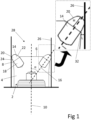
- Figure 1 shows a percussive drill bit 2 for drilling a bore hole 28 comprising a bit body 4 having a front face 6 surrounded by a gauge 8 and a longitudinal bit central axis 10; a plurality of front inserts (not shown) are embedded in the front face and a plurality of gauge inserts 14 are embedded in the gauge 8. Inserts are otherwise known as buttons.
- the gauge inserts 14 have a longitudinal insert central axis 16, a cylindrical shank portion 18 that is secured by interference fit into sockets that have been drilled into the drill bit body 4; and a working tip portion 20 that protrudes from the steel bit body 4.
- the inserts, both front and gauge are used for impacting and fracturing the rock being drilled.
- the front face inserts are arranged in one or more circumferential rows on the front face 6.
- the gauge inserts 14 extend around or adjacent to the peripheral edge of the drill bit 2.
- the gauge inserts 14 are in contact with a wall 26 of the bore hole 28.
- the gauge inserts 8 have a radially internal side 22 located on the side nearest to the bit central axis 10 and a radially external side 24 located on the side furthest from the bit central axis 10.
- the working tip portion 20 of the gauge inserts 14 have an asymmetric geometry wherein the volume of material on the radially external side 24 is greater than the volume of material on the radially internal side 22.
- the side of the gauge insert 14 having the higher volume of material is positioned on the side that is in contact with the wall 26 of the bore hole 28.
- An insert having asymmetric geometry is defined by when any one plane parallel to and passing through the insert central axis 16 divides the insert into two halves that are not mirror images. As opposed to an insert having symmetric geometry where there is symmetry across all planes parallel to and passing through the insert's central axis 16. If viewed from above and sectioned through a plane passing through the insert central axis 16, the half of the tip portion 20 that is radially further from the bit central axis 10 has a higher volume of material than the half of the tip portion 20 that is nearer to the bit central axis 10.
- L is for example > 0.6 mm or for example > 1.3 mm.
- the working tip portion 20 of the gauge inserts has a height (H). H is also equal to the height that the gauge inserts 14 protrudes from the gauge 8.
- L/H is for example >0.15 or for example > 0.2. Compared to a symmetrically shaped insert L is increased proportionately more for an asymmetrically shaped insert when the inserts have the same height (H).
- the diameter to the peripheral edge of the gauge inserts 14 at their widest point is greater when the gauge inserts 14 have an asymmetric geometry compared to when they have a symmetric geometry, therefore the diameter wear internal is increased when asymmetric gauge inserts 14 are used.
- the diameter of the gauge inserts 14 is between 6-24 mm, for example between 7-20 mm.
- ⁇ is between 10-50° or for example ⁇ is between 25-45°.
- Figure 3 shows that the working tip portion 20 of the gauge inserts 14 may have an asymmetric domed shape, also known as a domed shape.
- This geometry could also be referred to being a distorted or off-centre or lop-sided or askew dome geometry or an asymmetric or distorted or off-centre or lop-sided or askew spherical geometry.
- the gauge inserts 14 could also have any other suitable asymmetric geometry, such as semi-ballistic.
- ⁇ a second angle ( ⁇ ) on the gauge inserts 14 between the insert central axis 16 and a tangent of the working tip portion 20 of the gauge insert 14 located at a point 30 axially furthest from the bit central axis 10; wherein ⁇ is between 0-35. ⁇ is for example between 0-35° or for example between 3-25°.
- the cemented carbide used for the inserts 12, 14 comprises hard constituents in a metallic binder phase, and wherein the metallic binder phase content in the cemented carbide is between 4 to 20 wt%, for example between 5 to 15 wt%.
- the hard constituents comprise at least 50 wt% WC and possibly other hard constituents common in the art of making cemented carbides.
- the cemented carbide mining insert contains a hard phase comprising at least 80 wt% WC, for example at least 90 wt%.
- the metallic binder phase is for example selected from one or more of Fe, Co, and Ni.
- the metallic binder phase of the cemented carbide inserts 12, 14 comprises at least 80wt% of one or more metallic elements selected from Co, Ni and Fe.
- the metallic binder of the cemented carbide can comprise other elements that are dissolved in the metallic binder during sintering, such as W and C originating from the WC. Depending on what other types of hard constituents that are present, also other elements can be dissolved in the binder.
- the mean WC grain size in the cemented carbide is between 0.8 - 18 ⁇ m, for example between 1.5 - 10 ⁇ m, for example between 1 - 5 ⁇ m.
- the cemented carbide inserts 12, 14 further comprise gamma phase in a weight of between 0.8 - 10 wt%, for example between 1 - 8 wt%.
- the gamma phase forming carbides or nitrides or carbonitrides added could be any of Ta, Nb, Ti, Zr, Hf.
- the cemented carbide inserts 12, 14 further comprises Cr in such an amount that the mass ratio Cr/Co in the bulk is 0.04-0.19, for example between 0.075 - 0.17.
- the corrected CoM / wt% Co of a sintered sample is measured and calculated by using commercially available Foerster Koerzimat CS 1.096 equipment. The sample is weighed and then put into the magnetic coil as described in the Koerzimat CS 1.096 V3.09 manual.
- the cemented carbide inserts 12, 14 are subjected to a post processing surface hardening and toughening treatment.
- the sintered cemented carbide inserts are subjected to a tumbling treatment.
- the sintered cemented carbide inserts are subjected to a high energy tumbling treatment (HET).
- HET is considered to be a tumbling process wherein post tumbling a homogenous cemented carbide mining insert has been deformation hardened such that ⁇ HV3% ⁇ 9.72 - 0.00543*HV3 bulk , wherein the ⁇ HV3% is the percentage difference between the HV3 measurement at 0.3 mm from the surface compared the HV3 measurement in the bulk.
- HET could also be understood to mean a tumbling process that induces a hardness difference between 0.3 mm from the surface and the bulk of at least 20 HV3. HET could also be understood to mean that there is both a hardness and toughness increase induced from the surface to the bulk.
- the HET is conducted at an elevated temperature of or above 100°C, for example at a temperature of or above 200°C, for example at a temperature of between 200°C and 450°C.
- the inserts 12, 14 are pre-heated prior to the HET treatment.
- the HET is conducted in dry conditions. By “dry" conditions it is meant that no liquid is added to the process.
- the difference between an average hardness at 0.3 mm below the surface of the rock drill insert and an average hardness in the bulk (i.e., the innermost part) of the rock drill insert is at least 20 HV3, for example at least 30 HV3, for example at least 40 HV3, wherein hardness is measured according to ISO EN6507.
- Drill bits were tested in an underground mine in Sweden to compare the performance of symmetrical ballistic versus asymmetrical ballistic gauge inserts. In the tests the same bit bodies, the same number and distribution of inserts and the same insert diameters were used. The inserts used were all made from the same cemented carbide material, having a HV20 of 1440, Palmqvist Kic of 11 and D50 WC grain size measured using EBSD of 2.1 ⁇ m and were both subjected to the same HET treatment post sintering. The only difference was the geometry of the gauge inserts. Table 1 shows the diameter of the drill bit after drilling and the distance drilled. Table 1: Drilling test results Gauge insert geometry Diameter of drill bit after drilling (mm) Distance drilled (m) Symmetrical (comparison) 44.59 86.4 Asymmetrical (invention) 45.89 91.7
- the insert compression test method involves compressing a drill bit insert having a 10 mm diameter between two plane-parallel hard counter surfaces, at a constant displacement rate, until the failure of the insert.
- a test fixture based on the ISO 4506:2017 (E) standard "Hardmetals - Compression test” was used, with cemented carbide anvils grade H6F from Hyperion having a hardness exceeding 2000 HV, while the test method itself was adapted to toughness testing of rock drill inserts.
- the fixture was fitted onto an Instron 5989 test frame.
- the loading axis was identical with the axis of rotational symmetry of the inserts.
- the counter surfaces of the fixture fulfilled the degree of parallelism required in the ISO 4506:2017 (E) standard, i.e., a maximum deviation of 0.5 ⁇ m / mm.
- the tested inserts were loaded at a constant rate of crosshead displacement equal to 0.6 mm / min until failure, while recording the load-displacement curve.
- the compliance of the test rig and test fixture was subtracted from the measured load-displacement curve before test evaluation.
- Three inserts were tested per run.
- the counter surfaces were inspected for damage before each test. Insert failure was defined to take place when the measured load suddenly dropped by at least 1000 N.
- Inserts from the same batch which were subjected to a high energy tumbling treatment were also analyzed using the insert compression test, the results are shown in table 3 below: Table 3: Insert compression test results for insert post high energy tumbling Insert geometry Insert Crush strength (kN) Fracture Energy at crush (J) Symmetric ballistic 26.55 2.26 Asymmetric ballistic 35.0 3.30
Landscapes
- Engineering & Computer Science (AREA)
- Chemical & Material Sciences (AREA)
- Geology (AREA)
- Mining & Mineral Resources (AREA)
- Mechanical Engineering (AREA)
- Life Sciences & Earth Sciences (AREA)
- Physics & Mathematics (AREA)
- Fluid Mechanics (AREA)
- Environmental & Geological Engineering (AREA)
- General Life Sciences & Earth Sciences (AREA)
- Geochemistry & Mineralogy (AREA)
- Materials Engineering (AREA)
- Metallurgy (AREA)
- Organic Chemistry (AREA)
- Crystallography & Structural Chemistry (AREA)
- Earth Drilling (AREA)
Abstract
Description
- The present invention relates to an asymmetrically shaped cemented carbide inserts for percussive drilling applications.
- Cemented carbide inserts are used in percussive drill bits. Front inserts are typically arranged in circumferential rows on the front face of the drill bit with a row of gauge inserts extending around them adjacent to the peripheral edge of the bit face. When the gauge inserts wear down below a certain level the steel of the drill bit becomes in contact with the rock being drilled, this is known as anti-taper. The issue with anti-taper is that because the carbide inserts have worn down to the same diameter as the steel drill bit body there is no or less space for the cuttings to be removed, this results in a reduced rate of penetration or the drill bit getting stuck in hole as it is not possible to remove the cuttings. Consequently, wear on the steel drill bit body is accelerated and the lifetime of the drill bit is decreased.
- One possible way to delay the occurrence of anti-taper is to increase the protrusion height of the insert, however this will increase the likelihood of the inserts breaking.
- Therefore, the problem to be solved is how to avoid or delay the occurrence of anti-taper to improve the lifetime of the drill bit whilst maintaining the rate of drilling and without increasing the risk of insert breakage.
- According to a first aspect of the present invention it is an objective to provide a cemented carbide insert for mining or rock cutting applications comprising a percussive drill bit for drilling a bore hole (otherwise known as a drill hole) comprising a bit body having a front face surrounded by a gauge and a longitudinal bit central axis; and a plurality of gauge inserts embedded in the gauge; wherein the gauge inserts have a longitudinal insert central axis, a cylindrical shank portion; a working tip portion; an radially internal side located on the side nearest to the bit central axis and an radially external side located on the side furthest from the bit central axis; wherein the working tip portion of the gauge inserts have an asymmetric geometry; wherein the volume of material on the radially external side is greater than the volume of material on the radially internal side.
- Advantageously, the increased volume of material on the radially external side of the gauge inserts, i.e., the surface of the inserts that is in contact with the rock in the bore hole means that the distance between the steel bit body and the wall of the bore hole is increased. Consequently, the drilling distance before steel contact is made is increased without increasing the bending motion of the inserts which would otherwise result in premature fracture and therefore failure of the inserts. This will therefore decrease the likelihood / delay the occurrence of anti-taper thereby increasing the lifetime of the drill bit. Furthermore, the space between the steel bit body and rock for allowing the drill cuttings to be removed is maintained for longer and therefore the higher drilling speed can be sustained for a greater drilling distance. Overall, this means that the service life of the drill bit is increased.
- In some embodiments, there is a distance (L) between an outermost part of the bit body and a wall of the bore hole and wherein L > 0.6 mm. Advantageously, this provides sufficient space for the drill cuttings to be removed and delays the occurrence of anti-taper.
- In some embodiments, the working tip portion of the gauge inserts has a height (H) and wherein L/H is > 0.15. Advantageously, this range will enable improved wear resistance and increased drilling capacity before steel contact with the rock being drilled occurs without adversely affecting the moment force on the gauge inserts which would increase the risk of premature fracture of the inserts.
- In some embodiments the diameter of the gauge inserts is between 6-24 mm. Advantageously, this geometry range provides the balance between being small enough that there is sufficient space in the steel bit body to accommodate them and being large enough that they are sufficiently strong to avoid premature breakage. Inserts with this range of diameter size are suitable for both down-the-hole (DTH) and top hammer products.
- In some embodiments there is a first angle (α) between the insert central axis of the gauge inserts and the bit central axis; wherein α is between 10-50°. Advantageously, this provides the balance between there being sufficient space between the wall of the bore hole and the steel drill bit body without increasing the angle so greatly that the risk of insert failure increases.
- In some embodiments the working tip portion of the gauge inserts comprise between 5-60 % higher volume of material on their radially external side compared to the volume of material on their radially internal side. Advantageously, this delays the occurrence of anti-taper without decreasing the drilling rate of penetration.
- In some embodiments the working tip portion of the gauge inserts have a ballistic geometry. Advantageously, this geometry provides increased drilling speed.
- In some alternative embodiments the working tip portion of the gauge inserts has a domed geometry. Advantageously, this geometry provides improved wear resistance.
- In some embodiments there a second angle (β) on the gauge inserts between the insert central axis and a tangent of the working tip portion of the gauge insert located at a point axially furthest from the bit central axis; wherein β is between 0-35°. Ideally, β should be as low as possible as this provides the most optimal geometry for delaying / reducing the occurrence of anti-taper without being reduced so much that it results in difficulties with pressing which would result in cracking issues.
- In some embodiments, the cemented carbide used for the inserts comprises hard constituents in a metallic binder phase, wherein the metallic binder phase content in the cemented carbide is between 4 to 20 wt%. Advantageously, this provides an insert having sufficiently high hardness and toughness.
- In some embodiments, the metallic binder phase of the cemented carbide inserts comprises at least 80wt% of one or more metallic elements selected from Co, Ni and Fe.
- In some embodiments, the cemented carbide inserts further comprises gamma phase in a weight of between 0.8 - 10 wt%. Advantageously this provides a cemented carbide mining insert having improved wear resistance without increased brittleness. Therefore, the lifetime of the insert is increased. Further, it makes it easier to be able to use recycled carbide, that typically has higher gamma phase content that would be acceptable for cemented carbide grades that are commonly used for used mining or cutting applications.
- In some embodiments the cemented carbide inserts further comprises Cr in such an amount that the mass ratio Cr/Co in the bulk is between 0.04-0.19. Advantageously, the presence of the chromium improves the plastic deformation of the cemented carbide, this enables higher compressive stresses to be introduced into the carbide when it is treated with a surface hardening treatment, such as tumbling. This increase in compressive stress provides an apparent hardness increase which improves the wear resistance of the cemented carbide, without reducing the toughness.
- In some embodiments the cemented carbide inserts have a corrected CoM / wt% Co ratio between 0.70 - 0.81 and are substantially free of eta-phase wherein eta-phase is M6C or M12C where M = (Co, W, Cr); wherein said corrected CoM / wt% Co ratio is calculated according to:

- In some embodiments, the binder in the cemented carbide inserts has a gradient in concentration from one region of the insert to another region of the insert. Advantageously, this provides inserts having harder zones and tougher zones.
- A specific implementation of the present invention will now be described, by way of example only, and with reference to the accompanying drawings in which:
-
Figure 1 shows a schematic drawing of a drill bit comprising asymmetrically shaped gauge inserts. -
Figure 2 shows a side view of an asymmetric gauge insert having a ballistic geometry. -
Figure 3 shows a side view schematic drawing of an asymmetric gauge insert having a domed geometry. -
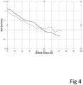
Figure 4 is a plot of the drilling rate of penetration (ROP) as a function of meters drilled comparing drill bits having symmetrical versus asymmetrical gauge inserts. -
Figure 1 shows apercussive drill bit 2 for drilling abore hole 28 comprising abit body 4 having a front face 6 surrounded by agauge 8 and a longitudinal bitcentral axis 10; a plurality of front inserts (not shown) are embedded in the front face and a plurality ofgauge inserts 14 are embedded in thegauge 8. Inserts are otherwise known as buttons. Thegauge inserts 14 have a longitudinal insertcentral axis 16, acylindrical shank portion 18 that is secured by interference fit into sockets that have been drilled into thedrill bit body 4; and a workingtip portion 20 that protrudes from thesteel bit body 4. The inserts, both front and gauge, are used for impacting and fracturing the rock being drilled. The front face inserts are arranged in one or more circumferential rows on the front face 6. Thegauge inserts 14 extend around or adjacent to the peripheral edge of thedrill bit 2. Thegauge inserts 14 are in contact with awall 26 of thebore hole 28. - The
gauge inserts 8 have a radiallyinternal side 22 located on the side nearest to the bitcentral axis 10 and a radiallyexternal side 24 located on the side furthest from the bitcentral axis 10. The workingtip portion 20 of the gauge inserts 14 have an asymmetric geometry wherein the volume of material on the radiallyexternal side 24 is greater than the volume of material on the radiallyinternal side 22. In other words, the side of thegauge insert 14 having the higher volume of material is positioned on the side that is in contact with thewall 26 of thebore hole 28. - An insert having asymmetric geometry is defined by when any one plane parallel to and passing through the insert
central axis 16 divides the insert into two halves that are not mirror images. As opposed to an insert having symmetric geometry where there is symmetry across all planes parallel to and passing through the insert'scentral axis 16. If viewed from above and sectioned through a plane passing through the insertcentral axis 16, the half of thetip portion 20 that is radially further from the bitcentral axis 10 has a higher volume of material than the half of thetip portion 20 that is nearer to the bitcentral axis 10. - The enlargement shown on
figure 1 shows that there is a distance (L) between anoutermost part 32 of thesteel bit body 4 and awall 26 of thebore hole 2. L is for example > 0.6 mm or for example > 1.3 mm. The workingtip portion 20 of the gauge inserts has a height (H). H is also equal to the height that the gauge inserts 14 protrudes from thegauge 8. L/H is for example >0.15 or for example > 0.2. Compared to a symmetrically shaped insert L is increased proportionately more for an asymmetrically shaped insert when the inserts have the same height (H). Fordrill bits 2 having the same diameter of thesteel bit body 4 at its widest point and gauge inserts 14 having the same height H, the diameter to the peripheral edge of the gauge inserts 14 at their widest point is greater when the gauge inserts 14 have an asymmetric geometry compared to when they have a symmetric geometry, therefore the diameter wear internal is increased when asymmetric gauge inserts 14 are used. - In some embodiments the diameter of the gauge inserts 14 is between 6-24 mm, for example between 7-20 mm.
- As shown in
figure 1 , there is a first angle (α) between the insertcentral axis 16 of the gauge inserts 14 and the bitcentral axis 10. For example, α is between 10-50° or for example α is between 25-45°. -
Figure 2 shows that the workingtip portion 20 of the gauge inserts 14 may have an asymmetric ballistic shape. This geometry may also be referred to as a distorted or off-centre or lop-sided or askew ballistic geometry or an asymmetric or distorted or off-centre or lop-sided or askew pointed geometry or an asymmetric or distorted or off-centre or lop-sided or askew peaked geometry. -
Figure 3 shows that the workingtip portion 20 of the gauge inserts 14 may have an asymmetric domed shape, also known as a domed shape. This geometry could also be referred to being a distorted or off-centre or lop-sided or askew dome geometry or an asymmetric or distorted or off-centre or lop-sided or askew spherical geometry. - The gauge inserts 14 could also have any other suitable asymmetric geometry, such as semi-ballistic.
- In some embodiments, the working tip portion of the gauge inserts 14 comprise between 5-60%, for example between 10-40% more volume of material on their radially
external side 24 compared to the volume of material on their radiallyinternal side 22. The volume of material on the radiallyexternal side 24 is considered to be the material in the half of the working tip furthest from the bitcentral axis 10 and the volume of material on the radiallyinternal side 22 is considered to be the material in the half of the working tip closest to the bitcentral axis 10. - As shown on
figure 2 , a second angle (β) on the gauge inserts 14 between the insertcentral axis 16 and a tangent of the workingtip portion 20 of thegauge insert 14 located at apoint 30 axially furthest from the bitcentral axis 10; wherein β is between 0-35. β is for example between 0-35° or for example between 3-25°. - In some embodiments, the cemented carbide used for the
inserts 12, 14 comprises hard constituents in a metallic binder phase, and wherein the metallic binder phase content in the cemented carbide is between 4 to 20 wt%, for example between 5 to 15 wt%. - Typically, the hard constituents comprise at least 50 wt% WC and possibly other hard constituents common in the art of making cemented carbides. In one embodiment of the method, the cemented carbide mining insert contains a hard phase comprising at least 80 wt% WC, for example at least 90 wt%.
- The metallic binder phase is for example selected from one or more of Fe, Co, and Ni. For example, the metallic binder phase of the cemented carbide inserts 12, 14 comprises at least 80wt% of one or more metallic elements selected from Co, Ni and Fe. The metallic binder of the cemented carbide can comprise other elements that are dissolved in the metallic binder during sintering, such as W and C originating from the WC. Depending on what other types of hard constituents that are present, also other elements can be dissolved in the binder.
- In some embodiments, the mean WC grain size in the cemented carbide is between 0.8 - 18 µm, for example between 1.5 - 10 µm, for example between 1 - 5 µm.
- In some embodiments, the cemented carbide inserts 12, 14 further comprise gamma phase in a weight of between 0.8 - 10 wt%, for example between 1 - 8 wt%. The gamma phase forming carbides or nitrides or carbonitrides added could be any of Ta, Nb, Ti, Zr, Hf.
- In some embodiments, the cemented carbide inserts 12, 14 further comprises Cr in such an amount that the mass ratio Cr/Co in the bulk is 0.04-0.19, for example between 0.075 - 0.17.
- In some embodiments, the cemented carbide inserts 12, 14 have a corrected CoM / wt% Co ratio between 0.70 - 0.81 and are substantially free of eta-phase wherein eta-phase is M6C or M12C where M = (Co, W, Cr); wherein said corrected CoM / wt% Co ratio is calculated according to:

- The corrected CoM / wt% Co of a sintered sample is measured and calculated by using commercially available Foerster Koerzimat CS 1.096 equipment. The sample is weighed and then put into the magnetic coil as described in the Koerzimat CS 1.096 V3.09 manual.
- In a different embodiment, the binder in the cemented carbide inserts 12, 14 has a gradient in binder concentration from one region of the insert to another.
- In some embodiments, the cemented carbide inserts 12, 14 are subjected to a post processing surface hardening and toughening treatment. For example, the sintered cemented carbide inserts are subjected to a tumbling treatment. For example, the sintered cemented carbide inserts are subjected to a high energy tumbling treatment (HET). HET is considered to be a tumbling process wherein post tumbling a homogenous cemented carbide mining insert has been deformation hardened such that ΔHV3% ≥ 9.72 - 0.00543*HV3bulk, wherein the ΔHV3% is the percentage difference between the HV3 measurement at 0.3 mm from the surface compared the HV3 measurement in the bulk. HET could also be understood to mean a tumbling process that induces a hardness difference between 0.3 mm from the surface and the bulk of at least 20 HV3. HET could also be understood to mean that there is both a hardness and toughness increase induced from the surface to the bulk.
- There are many different possible processes set ups that could be used to introduce HET, including the type of tumbler, the volume of media added (if any), the treatment time and the process set up, e.g., RPM for a centrifugal tumbler etc. Therefore, the most appropriate way to define HET is in terms of "any process set up that introduces a specific degree of deformation hardening in a homogenous cemented carbide mining insert consisting of WC-Co, having a mass of about 20g". In the present disclosure, HET is defined as a tumbling treatment that would introduce a hardness change, measured using HV3, after tumbling (ΔHV3%) of at least:


- HV3bulk is an average of at least 10 indentation points measured in the innermost (centre) of the cemented carbide mining insert and HV30.3mm is an average of at least 10 indentation points at 0.3mm below the tumbled surface of the cemented carbide mining insert. This is based on the measurements being made on a cemented carbide mining insert having homogenous properties. By "homogeneous properties" we mean that post sintering the hardness different is no more than 1% from the surface zone to the innermost bulk zone. The tumbling parameters used to achieve the deformation hardening described in equations (1) and (2) on a homogenous cemented carbide mining insert would be applied to cemented carbide bodies having a gradient property.
- HET tumbling may typically be performed using an ERBA 120, having a disc size of about 600 mm, run at about 180 RPM if the tumbling operation is either performed without media or with media that is larger in size than the inserts being tumbled, or at about 240 RPM if the media used is smaller in size than the inserts being tumbled; Using a Rösler tumbler, having a disc size of about 350 mm, at about 280 RPM if the tumbling operation is either performed without media or with media that is larger in size than the inserts being tumbled, or at about 320 RPM if the media used is smaller in size than the inserts being tumbled. Typically, the parts are tumbled for at least 40-80 minutes.
- In some embodiments, the HET is conducted at an elevated temperature of or above 100°C, for example at a temperature of or above 200°C, for example at a temperature of between 200°C and 450°C. In some embodiments, the
inserts 12, 14 are pre-heated prior to the HET treatment. In some embodiments the HET is conducted in dry conditions. By "dry" conditions it is meant that no liquid is added to the process. - In one embodiment the difference between an average hardness at 0.3 mm below the surface of the rock drill insert and an average hardness in the bulk (i.e., the innermost part) of the rock drill insert is at least 20 HV3, for example at least 30 HV3, for example at least 40 HV3, wherein hardness is measured according to ISO EN6507.
- Drill bits were tested in an underground mine in Sweden to compare the performance of symmetrical ballistic versus asymmetrical ballistic gauge inserts. In the tests the same bit bodies, the same number and distribution of inserts and the same insert diameters were used. The inserts used were all made from the same cemented carbide material, having a HV20 of 1440, Palmqvist Kic of 11 and D50 WC grain size measured using EBSD of 2.1 µm and were both subjected to the same HET treatment post sintering. The only difference was the geometry of the gauge inserts. Table 1 shows the diameter of the drill bit after drilling and the distance drilled.
Table 1: Drilling test results Gauge insert geometry Diameter of drill bit after drilling (mm) Distance drilled (m) Symmetrical (comparison) 44.59 86.4 Asymmetrical (invention) 45.89 91.7 - It can be seen from table 1 that the diameter of the drill bit post drilling was greater for the bit with asymmetrical inserts, even after a higher drilling distance, compared to the bit with the symmetric inserts. This illustrates that the wear to the steel body is reduced when asymmetrical inserts are used.
-
Figure 4 shows the rate of penetration (ROP) drilling speed as a function of drilled meters. The solid line is the results for the symmetric inserts and the dashed line is the results for the asymmetric inserts. It can be seen that the initial drilling speed for the bit having the symmetrically shaped gauge inserts was higher. However, after about 37 m of drilling steel contact for the bit having the symmetrically shaped gauge inserts occurs and the rate of penetration significantly decreases (i.e. the steel of the drill bit body comes in contact with the wall of the bore hole) meaning that there is less space for the cuttings to be removed which adversely effects the rate of penetration. Whereas for the bit having the asymmetrically shaped gauge inserts no steel contact occurs (i.e., there is still cemented carbide in contact with the wall of the bore hole) and so sufficient space for removal of cutting is maintained and therefore a higher rate of penetration is achieved for longer. - The insert compression test method involves compressing a drill bit insert having a 10 mm diameter between two plane-parallel hard counter surfaces, at a constant displacement rate, until the failure of the insert. A test fixture based on the ISO 4506:2017 (E) standard "Hardmetals - Compression test" was used, with cemented carbide anvils grade H6F from Hyperion having a hardness exceeding 2000 HV, while the test method itself was adapted to toughness testing of rock drill inserts. The fixture was fitted onto an Instron 5989 test frame.
- The loading axis was identical with the axis of rotational symmetry of the inserts. The counter surfaces of the fixture fulfilled the degree of parallelism required in the ISO 4506:2017 (E) standard, i.e., a maximum deviation of 0.5 µm / mm. The tested inserts were loaded at a constant rate of crosshead displacement equal to 0.6 mm / min until failure, while recording the load-displacement curve. The compliance of the test rig and test fixture was subtracted from the measured load-displacement curve before test evaluation. Three inserts were tested per run. The counter surfaces were inspected for damage before each test. Insert failure was defined to take place when the measured load suddenly dropped by at least 1000 N. Subsequent inspection of tested inserts confirmed that this in all cases this coincided with the occurrence of a macroscopically visible crack. The material strength was characterized by means of the total absorbed deformation energy until fracture. The summary of insert crush strength (kN) and fracture energy in Joules (J), required to crush the samples is shown in table 2 below for the as sintered inserts:
Table 2: Insert compression test results for sintered inserts. Insert geometry Insert Crush strength (kN) Fracture Energy at crush (J) Symmetric ballistic 8.90 0.43 Asymmetric ballistic 18.72 0.99 - Inserts from the same batch which were subjected to a high energy tumbling treatment were also analyzed using the insert compression test, the results are shown in table 3 below:
Table 3: Insert compression test results for insert post high energy tumbling Insert geometry Insert Crush strength (kN) Fracture Energy at crush (J) Symmetric ballistic 26.55 2.26 Asymmetric ballistic 35.0 3.30 - It can be seen from tables 2 and 3 that the insert crush strength and fracture energy at crush of the asymmetric inserts is higher for the asymmetric inserts compared to the symmetric inserts, which will reduce the probability of insert breakages and thus increase the lifetime of the inserts.
Claims (15)
- A percussive drill bit (2) for drilling a bore hole (28) comprising a bit body (4) having a front face (6) surrounded by a gauge (8); a longitudinal bit central axis (10); and a plurality of gauge inserts (14) embedded in the gauge (8);wherein the gauge inserts (8) have a longitudinal insert central axis (16), a cylindrical shank portion (18); a working tip portion (20); a radially internal side (22) located on the side nearest to the bit central axis (10) and a radially external side (24) on the side further from the bit central axis (10);characterized in that:
the working tip portion (20) of the gauge inserts (14) have an asymmetric geometry wherein the volume of material on the radially external side (24) is greater than the volume of material on the radially internal side (22). - The percussive drill bit (2) according to claim 1 wherein there is a distance (L) between an outermost part (32) of the bit body (4) and a wall (26) of the bore hole (28) and wherein L > 0.6 mm.
- The percussive drill bit (2) according to claim 1 or claim 2 wherein the working tip portion (20) of the gauge inserts (14) has a height (H) and wherein L/H is >0.15.
- The percussive drill bit (2) according to any of the previous claims wherein the diameter of the gauge inserts (14) is between 6-24 mm.
- The percussive drill bit (2) according to any of the previous claims wherein there is a first angle (α) between the insert central axis (16) of the gauge inserts (14) and the bit central axis (10); wherein α is between 10-50°.
- The percussive drill bit (2) according to any of the previous claims wherein the working tip portion (20) of the gauge inserts (14) comprise between 5-60 % more volume of material on their radially external side (24) compared to the volume of material on their radially internal side (22).
- The percussive drill bit (2) according to any of the previous claims wherein the working tip portion (20) of the gauge inserts (14) has a ballistic geometry.
- The percussive drill bit (2) according to any of claims 1-6 wherein the working tip portion (20) of the gauge inserts (14) has a domed geometry.
- The percussive drill bit (2) according to any of the previous claims wherein there is a second angle (β) on the gauge inserts (14) between the insert central axis (16) and a tangent of the working tip portion (20) of the gauge insert (14) located at the point axially furthest from the bit central axis (10); wherein β is between 0-35°.
- The percussive drill bit (2) according to any of the previous claims wherein the cemented carbide used for the inserts (12, 14) comprises hard constituents in a metallic binder phase, and wherein the metallic binder phase content in the cemented carbide is between 4 to 20 wt%.
- The percussive drill bit (2) according to claim 10 wherein the metallic binder phase of the cemented carbide inserts (12, 14) comprises at least 80wt% of one or more metallic elements selected from Co, Ni and Fe.
- The percussive drill bit (2) according to claim 10 or 11 wherein the cemented carbide inserts (12, 14) further comprises gamma phase in a weight of between 0.8 - 10 wt%.
- The percussive drill bit (2) according to any of claims 10 or 11 wherein the cemented carbide inserts (12, 14) further comprises Cr in such an amount that the mass ratio Cr/Co in the bulk is 0.04 - 0.19.
- The percussive drill bit (2) according to claim 13 wherein the cemented carbide inserts (12, 14) have a corrected CoM / wt% Co ratio between 0.70 - 0.81 and are substantially free of eta-phase wherein eta-phase is M6C or M12C where M = (Co, W, Cr); wherein said corrected CoM / wt% Co ratio is calculated according to:

- The percussive drill (2) according to any of the previous claims wherein the binder in the cemented carbide inserts (12, 14) has a gradient in concentration from one region of the insert (12, 14) to another region of the insert (12, 14).
Priority Applications (4)
| Application Number | Priority Date | Filing Date | Title |
|---|---|---|---|
| EP23199403.9A EP4528068A1 (en) | 2023-09-25 | 2023-09-25 | Mining tool with asymmetric cutting insert |
| AU2024352045A AU2024352045A1 (en) | 2023-09-25 | 2024-09-24 | Mining tool with asymmetric cutting insert |
| PCT/EP2024/076751 WO2025068162A1 (en) | 2023-09-25 | 2024-09-24 | Mining tool with asymmetric cutting insert |
| CN202480054566.4A CN121752801A (en) | 2023-09-25 | 2024-09-24 | Mining cutter with asymmetric cutting teeth |
Applications Claiming Priority (1)
| Application Number | Priority Date | Filing Date | Title |
|---|---|---|---|
| EP23199403.9A EP4528068A1 (en) | 2023-09-25 | 2023-09-25 | Mining tool with asymmetric cutting insert |
Publications (1)
| Publication Number | Publication Date |
|---|---|
| EP4528068A1 true EP4528068A1 (en) | 2025-03-26 |
Family
ID=88192097
Family Applications (1)
| Application Number | Title | Priority Date | Filing Date |
|---|---|---|---|
| EP23199403.9A Pending EP4528068A1 (en) | 2023-09-25 | 2023-09-25 | Mining tool with asymmetric cutting insert |
Country Status (4)
| Country | Link |
|---|---|
| EP (1) | EP4528068A1 (en) |
| CN (1) | CN121752801A (en) |
| AU (1) | AU2024352045A1 (en) |
| WO (1) | WO2025068162A1 (en) |
Citations (14)
| Publication number | Priority date | Publication date | Assignee | Title |
|---|---|---|---|---|
| EP0140849A2 (en) * | 1983-09-20 | 1985-05-08 | Santrade Ltd. | Rock drill bit |
| EP0182759A1 (en) * | 1984-11-13 | 1986-05-28 | Santrade Ltd. | Cemented carbide body used preferably for rock drilling and mineral cutting |
| WO1996012086A1 (en) * | 1994-10-12 | 1996-04-25 | Sandvik Ab | A rock drill bit and cutting inserts |
| US5588497A (en) * | 1993-10-28 | 1996-12-31 | Galison Drilling (Proprietary) Limited | Mounting drill buttons |
| GB2334278A (en) * | 1998-02-13 | 1999-08-18 | Smith International | Cutting element for rock bit |
| WO2002029198A1 (en) * | 2000-10-05 | 2002-04-11 | Kennametal Inc. | Cutting insert for percussion drill bit |
| US20020153174A1 (en) * | 1999-11-25 | 2002-10-24 | Johan Linden | Percussive rock drill bit and buttons therefor and method for manufacturing drill bit |
| EP2011890A1 (en) * | 2007-06-01 | 2009-01-07 | Sandvik Intellectual Property AB | Fine grained cemented carbide with refined structure |
| US20100263939A1 (en) * | 2006-10-26 | 2010-10-21 | Hall David R | High Impact Resistant Tool with an Apex Width between a First and Second Transitions |
| WO2012142919A1 (en) * | 2011-04-18 | 2012-10-26 | Huimin Li | Insert with the cutting edge and its rock drill bit |
| US20130105231A1 (en) * | 2011-11-01 | 2013-05-02 | Tdy Industries, Inc. | Earth boring cutting inserts and earth boring bits including the same |
| WO2018060125A1 (en) * | 2016-09-28 | 2018-04-05 | Sandvik Intellectual Property Ab | A rock drill insert |
| WO2022263477A1 (en) * | 2021-06-16 | 2022-12-22 | Sandvik Mining And Construction Tools Ab | Cemented carbide insert with eta‐phase core |
| WO2023285316A1 (en) * | 2021-07-14 | 2023-01-19 | Sandvik Mining And Construction Tools Ab | Cemented carbide insert for mining or cutting applications comprising gamma phase carbide |
-
2023
- 2023-09-25 EP EP23199403.9A patent/EP4528068A1/en active Pending
-
2024
- 2024-09-24 AU AU2024352045A patent/AU2024352045A1/en active Pending
- 2024-09-24 WO PCT/EP2024/076751 patent/WO2025068162A1/en active Pending
- 2024-09-24 CN CN202480054566.4A patent/CN121752801A/en active Pending
Patent Citations (15)
| Publication number | Priority date | Publication date | Assignee | Title |
|---|---|---|---|---|
| EP0140849A2 (en) * | 1983-09-20 | 1985-05-08 | Santrade Ltd. | Rock drill bit |
| EP0182759A1 (en) * | 1984-11-13 | 1986-05-28 | Santrade Ltd. | Cemented carbide body used preferably for rock drilling and mineral cutting |
| US5588497A (en) * | 1993-10-28 | 1996-12-31 | Galison Drilling (Proprietary) Limited | Mounting drill buttons |
| WO1996012086A1 (en) * | 1994-10-12 | 1996-04-25 | Sandvik Ab | A rock drill bit and cutting inserts |
| GB2334278A (en) * | 1998-02-13 | 1999-08-18 | Smith International | Cutting element for rock bit |
| US20020153174A1 (en) * | 1999-11-25 | 2002-10-24 | Johan Linden | Percussive rock drill bit and buttons therefor and method for manufacturing drill bit |
| WO2002029198A1 (en) * | 2000-10-05 | 2002-04-11 | Kennametal Inc. | Cutting insert for percussion drill bit |
| US20100263939A1 (en) * | 2006-10-26 | 2010-10-21 | Hall David R | High Impact Resistant Tool with an Apex Width between a First and Second Transitions |
| EP2011890A1 (en) * | 2007-06-01 | 2009-01-07 | Sandvik Intellectual Property AB | Fine grained cemented carbide with refined structure |
| WO2012142919A1 (en) * | 2011-04-18 | 2012-10-26 | Huimin Li | Insert with the cutting edge and its rock drill bit |
| US20130105231A1 (en) * | 2011-11-01 | 2013-05-02 | Tdy Industries, Inc. | Earth boring cutting inserts and earth boring bits including the same |
| WO2018060125A1 (en) * | 2016-09-28 | 2018-04-05 | Sandvik Intellectual Property Ab | A rock drill insert |
| US20200030886A1 (en) * | 2016-09-28 | 2020-01-30 | Sandvik Intellectual Property Ab | Rock drill insert |
| WO2022263477A1 (en) * | 2021-06-16 | 2022-12-22 | Sandvik Mining And Construction Tools Ab | Cemented carbide insert with eta‐phase core |
| WO2023285316A1 (en) * | 2021-07-14 | 2023-01-19 | Sandvik Mining And Construction Tools Ab | Cemented carbide insert for mining or cutting applications comprising gamma phase carbide |
Also Published As
| Publication number | Publication date |
|---|---|
| CN121752801A (en) | 2026-03-27 |
| AU2024352045A1 (en) | 2026-02-26 |
| WO2025068162A1 (en) | 2025-04-03 |
Similar Documents
| Publication | Publication Date | Title |
|---|---|---|
| US10954938B2 (en) | Valve seats and valve assemblies for fluid end applications | |
| RU2526627C2 (en) | Sintered hard metal part and method to this end | |
| USRE47605E1 (en) | Polycrystalline diamond elements, cutting elements, and related methods | |
| US20220001445A1 (en) | Binder redistribution within a cemented carbide mining insert | |
| US12319990B2 (en) | Gradient cemented carbide body and method of manufacturing thereof | |
| EP4076801B1 (en) | Method of treating a mining insert | |
| WO2025068162A1 (en) | Mining tool with asymmetric cutting insert | |
| US20240295012A1 (en) | Cemented carbide insert for mining or cutting applications comprising gamma phase carbide | |
| US12559806B2 (en) | Cemented carbide insert with eta-phase core | |
| OA21468A (en) | Cemented carbide insert for mining or cutting applications comprising gamma phase carbide | |
| EP4306671A1 (en) | Rock drill insert | |
| CA3136775C (en) | Gradient cemented carbide body and method of manufacturing thereof | |
| RU2799380C2 (en) | Redistribution of binder in a cemented carbide drill bit insert | |
| US20260139338A1 (en) | Cemented carbide insert with eta-phase core | |
| BR112021026361B1 (en) | METHOD FOR PRODUCING A CARBIDE MINING INSERT AND CARBIDE MINING INSERT | |
| Rogan et al. | Fatigue strength of cemented tungsten carbides and tool steels subjected to cyclic compressive stresses |
Legal Events
| Date | Code | Title | Description |
|---|---|---|---|
| PUAI | Public reference made under article 153(3) epc to a published international application that has entered the european phase |
Free format text: ORIGINAL CODE: 0009012 |
|
| STAA | Information on the status of an ep patent application or granted ep patent |
Free format text: STATUS: THE APPLICATION HAS BEEN PUBLISHED |
|
| AK | Designated contracting states |
Kind code of ref document: A1 Designated state(s): AL AT BE BG CH CY CZ DE DK EE ES FI FR GB GR HR HU IE IS IT LI LT LU LV MC ME MK MT NL NO PL PT RO RS SE SI SK SM TR |
|
| STAA | Information on the status of an ep patent application or granted ep patent |
Free format text: STATUS: REQUEST FOR EXAMINATION WAS MADE |
|
| 17P | Request for examination filed |
Effective date: 20250926 |
|
| REG | Reference to a national code |
Ref country code: DE Ref legal event code: R079 Free format text: PREVIOUS MAIN CLASS: E21B0010360000 Ipc: E21B0010567000 Ref country code: DE Ref legal event code: R079 Ref document number: 602023017676 Country of ref document: DE Free format text: PREVIOUS MAIN CLASS: E21B0010360000 Ipc: E21B0010567000 |
|
| GRAP | Despatch of communication of intention to grant a patent |
Free format text: ORIGINAL CODE: EPIDOSNIGR1 |
|
| STAA | Information on the status of an ep patent application or granted ep patent |
Free format text: STATUS: GRANT OF PATENT IS INTENDED |
|
| INTG | Intention to grant announced |
Effective date: 20260216 |
|
| RIC1 | Information provided on ipc code assigned before grant |
Ipc: E21B 10/567 20060101AFI20260206BHEP Ipc: E21B 10/36 20060101ALI20260206BHEP Ipc: C22C 29/06 20060101ALI20260206BHEP Ipc: C22C 29/08 20060101ALI20260206BHEP |
|
| GRAS | Grant fee paid |
Free format text: ORIGINAL CODE: EPIDOSNIGR3 |
|
| GRAA | (expected) grant |
Free format text: ORIGINAL CODE: 0009210 |
|
| STAA | Information on the status of an ep patent application or granted ep patent |
Free format text: STATUS: THE PATENT HAS BEEN GRANTED |