EP4528042A2 - Drain cleaner - Google Patents
Drain cleaner Download PDFInfo
- Publication number
- EP4528042A2 EP4528042A2 EP24196642.3A EP24196642A EP4528042A2 EP 4528042 A2 EP4528042 A2 EP 4528042A2 EP 24196642 A EP24196642 A EP 24196642A EP 4528042 A2 EP4528042 A2 EP 4528042A2
- Authority
- EP
- European Patent Office
- Prior art keywords
- housing
- drum
- cover
- drain cleaner
- drain
- Prior art date
- Legal status (The legal status is an assumption and is not a legal conclusion. Google has not performed a legal analysis and makes no representation as to the accuracy of the status listed.)
- Pending
Links
Images





Classifications
-
- E—FIXED CONSTRUCTIONS
- E03—WATER SUPPLY; SEWERAGE
- E03F—SEWERS; CESSPOOLS
- E03F9/00—Arrangements or fixed installations methods or devices for cleaning or clearing sewer pipes, e.g. by flushing
- E03F9/002—Cleaning sewer pipes by mechanical means
- E03F9/005—Apparatus for simultaneously pushing and rotating a cleaning device carried by the leading end of a cable or an assembly of rods
-
- B—PERFORMING OPERATIONS; TRANSPORTING
- B08—CLEANING
- B08B—CLEANING IN GENERAL; PREVENTION OF FOULING IN GENERAL
- B08B9/00—Cleaning hollow articles by methods or apparatus specially adapted thereto
- B08B9/02—Cleaning pipes or tubes or systems of pipes or tubes
- B08B9/027—Cleaning the internal surfaces; Removal of blockages
- B08B9/04—Cleaning the internal surfaces; Removal of blockages using cleaning devices introduced into and moved along the pipes
- B08B9/043—Cleaning the internal surfaces; Removal of blockages using cleaning devices introduced into and moved along the pipes moved by externally powered mechanical linkage, e.g. pushed or drawn through the pipes
- B08B9/045—Cleaning the internal surfaces; Removal of blockages using cleaning devices introduced into and moved along the pipes moved by externally powered mechanical linkage, e.g. pushed or drawn through the pipes the cleaning devices being rotated while moved, e.g. flexible rotating shaft or "snake"
-
- B—PERFORMING OPERATIONS; TRANSPORTING
- B08—CLEANING
- B08B—CLEANING IN GENERAL; PREVENTION OF FOULING IN GENERAL
- B08B9/00—Cleaning hollow articles by methods or apparatus specially adapted thereto
- B08B9/02—Cleaning pipes or tubes or systems of pipes or tubes
- B08B9/027—Cleaning the internal surfaces; Removal of blockages
- B08B9/04—Cleaning the internal surfaces; Removal of blockages using cleaning devices introduced into and moved along the pipes
- B08B9/043—Cleaning the internal surfaces; Removal of blockages using cleaning devices introduced into and moved along the pipes moved by externally powered mechanical linkage, e.g. pushed or drawn through the pipes
- B08B9/047—Cleaning the internal surfaces; Removal of blockages using cleaning devices introduced into and moved along the pipes moved by externally powered mechanical linkage, e.g. pushed or drawn through the pipes the cleaning devices having internal motors, e.g. turbines for powering cleaning tools
-
- E—FIXED CONSTRUCTIONS
- E03—WATER SUPPLY; SEWERAGE
- E03C—DOMESTIC PLUMBING INSTALLATIONS FOR FRESH WATER OR WASTE WATER; SINKS
- E03C1/00—Domestic plumbing installations for fresh water or waste water; Sinks
- E03C1/12—Plumbing installations for waste water; Basins or fountains connected thereto; Sinks
- E03C1/30—Devices to facilitate removing of obstructions in waste-pipes or sinks
- E03C1/302—Devices to facilitate removing of obstructions in waste-pipes or sinks using devices moved through the pipes
Definitions
- the present invention relates to drain cleaners used to clean and remove debris from pipes and other conduits.
- Drain cleaners typically include a drum containing a cable or snake.
- the cable is extendable out of the drum and into a conduit to be cleaned. Rotating the drum spins the cable to clean and remove debris from the conduit.
- Some drain cleaners are handheld and can be supported by a user.
- the drain cleaner may include a cover to enclose the drum and prevent a user from accessing the drum during operation of the drain cleaner.
- a drain cleaner including: a housing having an interior; a cover coupled to the housing over the interior; a nose assembly extending forwardly from the cover to define a first grip; a handle assembly extending rearwardly from the housing and including a second grip; a motor positioned within the housing, the motor defining a rotation axis; a drum positioned within the interior, the drum operable to be rotated by the motor relative to the housing; a flexible cable stored within the drum, the flexible cable configured to be extended out of the drum and into a drain; and an auxiliary handle extending from the cover and including a third grip, the auxiliary handle defining an opening between the third grip and the cover.
- the techniques described herein relate to a drain cleaner, wherein the auxiliary handle is removably coupled to the cover.
- the techniques described herein relate to a drain cleaner, wherein the auxiliary handle extends away from the cover at an angle between 30 degrees and 60 degrees relative to the rotation axis.
- the techniques described herein relate to a drain cleaner, wherein the handle assembly includes a stand positioned beneath a center of gravity of the drain cleaner.
- the techniques described herein relate to a drain cleaner, wherein the handle assembly includes a battery receptacle configured to receive a battery pack.
- the techniques described herein relate to a drain cleaner, wherein the third grip has a length that extends perpendicular to the rotation axis.
- the techniques described herein relate to a drain cleaner, wherein the auxiliary handle includes two flanges extending from ends of the third grip and coupled to opposing sides of the cover.
- the techniques described herein relate to a drain cleaner, wherein the auxiliary handle includes a cylindrical tube.
- the techniques described herein relate to a drain cleaner, wherein the cover is pivotably coupled to the housing and moveable between a closed position, in which the drum is enclosed within the interior, and an open position, in which the drum is accessible.
- a drain cleaner including: a housing having an interior; a motor positioned within the housing, the motor defining a rotation axis; a drum positioned within the housing, the drum operable to be rotated by the motor relative to the housing; a flexible cable stored within the drum, the flexible cable configured to be extended out of the drum and into a drain; and a cover pivotably coupled to the housing, the cover pivotable between a closed position, in which the drum is enclosed within the interior, and an open position, in which the drum is accessible.
- the techniques described herein relate to a drain cleaner, wherein when the cover is in the open position, the drum is removable from the interior of the housing.
- the techniques described herein relate to a drain cleaner, wherein the drum is supported by an inner cone within the interior of the housing.
- the techniques described herein relate to a drain cleaner, further including a first latch mechanism coupled to the housing and the cover, wherein the first latch mechanism is moveable from a first position, in which the cover is secured to the housing, and a second position, in which the cover is able to move between the open and closed positions.
- the techniques described herein relate to a drain cleaner, further including a second latch mechanism coupled to the housing and the cover, wherein the second latch mechanism is moveable between a first position, in which, the cover is not pivotable relative to the housing, and a second position, in which the cover is pivotable between the open and closed positions.
- the techniques described herein relate to a drain cleaner, wherein the first and second latch mechanisms are positioned on opposite sides of the housing from one another.
- the techniques described herein relate to a drain cleaner, wherein the cover is pivotable about an axis that is transverse to the rotation axis.
- the techniques described herein relate to a system including: an organization system including a cleat; and a drain cleaner including, a housing, a motor positioned within the housing, a handle assembly extending from the housing, the handle assembly including a stand with an opening, the opening configured to receive the cleat to connect the drain cleaner to the organization system, a drum positioned within the housing, the drum operable to be rotated by the motor relative to the housing, and a flexible cable stored within the drum, the flexible cable configured to be extended out of the drum and into a drain.
- the techniques described herein relate to a system, wherein the cleat is diamond shaped.
- the techniques described herein relate to a system, wherein the organization system includes a rail configured to be mounted to a wall, and wherein the cleat extends from the rail.
- the techniques described herein relate to a system, wherein the cleat is a first cleat, and wherein the organization system further includes a second cleat.
- FIGS. 1-3 illustrate a drain cleaner 10.
- the illustrated drain cleaner 10 may include a housing 14, a cover 18 coupled to the housing 14, a handle assembly 22, and a nose assembly 26.
- the drain cleaner 10 may also include a motor 30 and a drive mechanism 34 with an output shaft 38 positioned within the housing 14.
- the output shaft 38 may be coupled to a drum 42 to selectively rotate the drum 42 about a rotation axis 46 that extends through the output shaft 38 and the center of the nose assembly 26.
- the drain cleaner 10 may further include a flexible cable 50 that is stored within the drum 42 and extends out of the nose assembly 26.
- the cable 50 may be insertable into a drain, or other conduit, for cleaning the drain.
- the cable 50 may include an auger head or other tool attachment at its distal end.
- the handle assembly 22 may extend rearwardly from the housing 14.
- the handle assembly 22 may include a grip 54 that is configured to be grasped by a user for carrying and operating the drain cleaner 10.
- the handle assembly 22 may support an actuator 58 (e.g., a trigger) adjacent the grip 54.
- the actuator 58 may be actuatable (e.g., depressible) by a user to selectively energize the motor 30 and, thereby, operate the drain cleaner 10.
- the illustrated handle assembly 22 may also include a battery receptacle 62 ( FIG. 1 ) for receiving and supporting a battery pack, such as a power tool battery pack.
- the battery receptacle 62 may include terminals that electrically connect the battery pack to the motor 30 and the actuator 58.
- the handle assembly 22 may support or connect to a power cord to electrically connect the motor 30 to an AC power source.
- the battery receptacle 62 may be on a side of the handle assembly 22 so that the battery pack is received in the battery receptacle 62 in a direction orthogonal to the rotation axis 46.
- the battery receptacle 62 may be positioned elsewhere on the handle assembly 22 or drain cleaner 10.
- the battery receptacle 62 may be positioned on a bottom side of the handle assembly 22 as shown in FIG. 15 .
- the illustrated handle assembly 22 may further include a stand 66.
- the stand 66 may be a base.
- the stand 66 may be positioned generally beneath the housing 14 and the motor 30. More particularly, the stand 66 may be positioned beneath a center of gravity of the drain cleaner 10, which is principally defined by the motor 30, the drive mechanism 34, the cable 50, and the battery pack (if present) of the drain cleaner 10.
- the stand 66 may include a bottom surface 70 that is configured to engage and rest on a support surface 74 (e.g., a table, a workbench, a countertop, the floor, etc.). In one embodiment, the stand 66 may provide ease of use during operation.
- the cover 18 may include an auxiliary handle 78 extending away from the cover 18.
- the auxiliary handle 78 may be a removable auxiliary handle.
- the auxiliary handle 78 may be coupled to a top portion 82 of the cover 18 using fasteners 86 (e.g., screws, bolts, etc.).
- the auxiliary handle 78 may be coupled to the cover 18 using four fasteners 86 (i.e., two on each side of the auxiliary handle 78).
- the auxiliary handle 78 may define a grip 87 and may include two flanges 89 extending from the ends of the grip 87.
- the grip 87 may be a hollow cylindrical tube that a user can grasp.
- the grip 87 may have a length that extends perpendicular to the rotation axis 46.
- the flanges 89 may couple to opposing sides (i.e., a first side and a second side) of the cover 18.
- Each flange 89 of the auxiliary handle 78 may include a rib 88 with a geometric shape that corresponds to a recess 90 on the top portion 82 of the cover 18.
- the rib 88 and the recess 90 may strengthen the connection between the auxiliary handle 78 and the cover 18 and allow for better support during operation by a user.
- the fasteners 86 may be removed with a tool (e.g., screwdriver) to remove the auxiliary handle 78.
- the fasteners 86 may be snaps, magnets, or other suitable fasteners that can be disconnected without a tool (e.g., may instead be disconnected by applying a suitable force).
- an opening 92 FIG. 1
- the auxiliary handle 78 may extend away from the cover 18 at an angle A ( FIG. 3 ) relative to the rotation axis 46.
- the angle A may be an oblique angle. In the illustrated embodiment, the angle A may be between 30 degrees and 60 degrees. In other embodiments, the angle A may be less than 30 degrees or more than 60 degrees.
- a user may place one hand on the grip 54 and the other on the auxiliary handle 78 to support and stabilize the drain cleaner 10 during transport or operation.
- the drum 42 may be supported within the housing 14 by an inner cone 94.
- the inner cone 94 may be coupled to the drive mechanism 34 such that rotation of the motor 30 is transmitted to the drum 42 through the drive mechanism 34 and inner cone 94. Friction between the inner surface of the drum 42 and the cable 50 may cause the cable 50 to rotate or spin with the drum 42. As the drum 42 rotates, the cable 50 may also rotate.
- the drain cleaner 10 may include a feed mechanism, described below, that engages the cable 50 as it rotates, causing the cable 50 to be extended into the drain or retracted from the drain.
- the illustrated drive mechanism 34 may include a gear train having, for example, planetary gear arrangements and the output shaft 38 that transmit rotation of the motor 30 to the drum 42.
- the inner cone 94 and the drum 42 are integrally coupled together so that the drum 42 and the inner cone 96 are removed together from the interior of the housing 14.
- the drum 42 may be threadably coupled to the inner cone 94.
- the drum 42 may be coupled directly to the drive mechanism 34 using other suitable means to transmit force (e.g., rotation) from the drive mechanism 34 to the drum 42.
- other suitable drive mechanisms may also or alternatively be employed.
- the drum 42 may be removed from within the housing 14 and replaced with another drum.
- the illustrated drum 42 may include a front portion or a nose piece 98 that extends away from the drum 42 and into the nose assembly 26.
- the nose piece 98 may guide the cable 50 from the drum 42 into the nose assembly 26.
- the nose piece 98 of the drum 42 may be positioned within a bearing 100 when the cover 18 is in a closed position.
- the bearing 100 may allow the drum 42 to rotate relative to the nose assembly 26 during operation.
- the nose assembly 26 may be positioned forward of the housing 14 and may provide an additional grip for a user to hold the drain cleaner 10 during operation. For example, a user can grasp the grip 54 of the handle assembly 22 with one hand to operate the actuator 58, and can grasp the nose assembly 26 with the other hand to help guide the drain cleaner 10.
- the grip of the nose assembly 26 may have a length that is parallel to, or even coaxial with, the rotation axis 46.
- the grip 87 of the auxiliary handle 78 may be perpendicular to the grip of the nose assembly 26.
- the nose assembly 26 may also provide a lock mechanism 102 for the drain cleaner 10.
- the lock mechanism 102 may include two spring clips 106 ( FIG. 3 ) positioned within the nose assembly 26 on opposite sides of the nose piece 98 of the drum 42.
- the lock mechanism 102 may include two tabs 110 that extend from an interior of the nose assembly 26.
- the lock mechanism 102 may be rotatable about the rotation axis 46 from a locked position to an unlocked position. When the lock mechanism 102 is rotated to the locked position, a cam surface (not shown) may push the spring clips 106 inwardly to engage the cable 50. In this position, the cable 50 may be forced to rotate with the drum 42.
- the spring clips 106 may be biased apart from each other and disengage the cable 50 so that the cable 50 can be fed out of or into the drum 42.
- the lock mechanism 102 may be biased away from the drum 42 (i.e., toward an unlocked position) by a spring or other biasing member.
- the lock mechanism 102 may slide axially between the locked and unlocked positions.
- the drain cleaner 10 may further include a cable feed mechanism 114 that helps guide and drive the cable 50 out of the drum 42 and into a drain.
- the cable feed mechanism 114 may be supported on the front end of the nose assembly 26.
- the cable feed mechanism 114 may include a plurality of rollers 118 that are moveable to engage the cable 50.
- the cable feed mechanism 114 may be rotatable about the rotation axis 46 between a manual feed position and an auto-feed position. When the cable feed mechanism 114 is in the manual feed position, the rollers 118 do not engage the cable 50, allowing a user to manually pay out or push in the cable 50 from the drum 42.
- the rollers 118 may move radially inward to engage the cable 50. With the cable 50 engaged by the rollers 118, when a user pushes the trigger 58 and the drum 42 rotates, the rollers 118 may allow the cable 50 to be paid out automatically from the drum 42 and into a drain or conduit.
- the drum 42 may be removable from an interior of the housing 14.
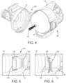
- the cover 18 may be moveable from a closed position ( FIG. 1 ) to an open position ( FIG. 4 ) to allow access to the drum 42 and cable 50 within the housing 14.
- the drum 42 When in the closed position, the drum 42 may be completely enclosed by the housing 14 and the cover 18.
- a first latch mechanism 122 may be positioned on a first side of the housing 14.
- the first latch mechanism 122 may include an actuator 126 with a wire bar 130 coupled thereto.
- the actuator 126 may be pivotable from a first position ( FIG. 5 ) to a second position ( FIG. 6 ) to disengage the cover 18.
- the drain cleaner 10 may include other suitable latch mechanisms for the first latch mechanism 122.
- the drain cleaner 10 may also include a second latch mechanism 138 on an opposite side of the housing 14 from the first latch mechanism 122.
- the second latch mechanism 138 may also be referred to as a hinge.
- the second latch mechanism 138 may include an actuator 142 that is pivotable from a first position ( FIG. 7 ) to a second position ( FIG. 8 ) to release the cover 18 from the housing 14.
- the actuator 142 may be positioned within a support 146 of the housing 14 and may include a buckle 150 that corresponds to a rib 154 on the cover 18.
- the actuator 142 may be pivoted from the first position to the second position to release the cover 18 from the housing 14.
- the drain cleaner 10 may include other suitable latch mechanisms for the second latch mechanism 138.
- the support 146 may define a channel 158 with a track 162 that the rib 154 of the cover 18 is moveable within.
- the cover 18 may slide forward to a pivoting position.
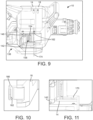
- the rib 154 on the cover 18 may include two protrusions 166 ( FIG. 10 ) on opposite sides that engage the track 162 (e.g., one protrusion 166 may be positioned within an upper portion of the track 162 and the other protrusion 166 may be positioned within a lower portion of the track 162).
- the protrusions 166 may slide along the track 162 until the protrusions 166 reach a bulb-shaped end 170 ( FIG. 11 ) of the track 162. Once the protrusions 166 are within the bulb-shaped end 170, the cover 18 may be pivoted about an axis 174 defined by the protrusions 166 from the closed position to the open position to allow access to the drum 42 and cable 50. That is, the cover 18 may first slide linearly away from the housing 14, and then may pivot relative to the housing 14.
- the axis 174 may be transverse to the rotation axis 46. More particularly, the axis 174 may be spaced apart from and perpendicular to the rotation axis 46.
- a user may first release the first latch mechanism 122 by pivoting the actuator 126 from the first position to the second position, releasing the wire bar 130 from the clasp 134.
- a user may release the second latch mechanism 138 by pivoting the actuator 142 from the first position to the second position, releasing the buckle 150 from the rib 154 of the cover 18.
- the user may release the second latch mechanism 138 before the first latch mechanism 122, or may release both latch mechanisms 122, 138 simultaneously.
- a user may slide the cover 18 away from the housing 14 until the cover 18 is in the pivoting position. As the cover 18 is pulled forward, the nose piece 98 of the drum 42 may be released from the cover 18.
- sliding the cover 18 axially along the rotation axis 46 may allow the nose piece 98 to disengage the bearing 100 in the nose assembly 26 allowing the cover 18 to therefore pivot.
- a user may freely rotate the cover 18 about the axis 174 to gain access to the drum 42 and cable 50.
- a user may remove the cable 50 through a front opening 178 of the drum 42 or wind the cable 50 into the drum 42.
- the user may completely remove the drum 42 from the housing 14 by gently pulling the drum 42 away from the housing 14. As the drum 42 is pulled away from the housing 14, the drum 42 and the inner cone 94 may be decoupled from the output shaft 38 of the drive mechanism 34.
- the drum 42 While removed, the drum 42 may be cleaned and returned to within the interior of the housing 14. Alternatively, once the drum 42 is removed, the drum 42 may be exchanged with a different drum. For example, the drum 42 may be exchanged with a newer drum and cable or for a drum with a different size/type of cable.
- the drain cleaner 10 may include the grip 54, the auxiliary handle 78, and the nose assembly 26 that a user may choose to position their hands on when handling the drain cleaner 10.
- providing a drain cleaner 10 with a pivotable front cover 18 allows easier access to the drum 42 and cable 50 stored within the housing 14. It should be noted that providing the drain cleaner 10 with first and second latch mechanisms 122, 138 to move the cover 18 to an open position allows for easy access to the interior of the housing 14 without needing an additional tool or the need to remove fasteners.
- the drain cleaner 10 may be supported by an organization system 210.
- the organization system 210 may be a wall organization system, such as the one disclosed in U.S. Application Serial No. 17/396,282, filed August 6, 2021 , the entire contents of which are incorporated by reference herein.
- the organization system 210 may also be mounted to other suitable structures (e.g., cabinets, tables, etc.) or may be part of a storage box, tool box, or the like.
- the organization system 210 may include a mount or rail 214 having at least one cleat 218 that may be supported on a surface or a wall W. In the illustrated embodiment, the cleat 218 may be diamond-shaped.
- the cleat 218 may have another shape (e.g., hexagonal, octagonal, etc.).
- the stand 66 of the handle assembly 22 may include an opening 222 having a shape that corresponds to and receives the cleat 218.
- the engagement between the cleat 218 and the opening 222 of the drain cleaner 10 may be a locking engagement, or a gravitational engagement similar to a French cleat.
- the drain cleaner 10 can be attached to the support surface (e.g., a wall W) through the rail 214.
- the engagement between the cleat 218 and the opening 222 may be referred to an over-the-diamond interface since the opening 222 receives the cleat 218.
- FIGS. 15 and 16 illustrate a drain cleaner 310 according to another embodiment.
- the drain cleaner 310 may be similar to the drain cleaner 10 described above with like features being represented with like reference numbers.
- the drain cleaner 310 may include the handle assembly 22, however, the handle assembly 22 may include a flange portion 314 connecting the battery receptacle 62 to the housing 14.
- the flange portion may include a reduced width compared to the rest of the handle assembly 22.
- the flange portion may be configured to engage the space between two cleats 218 of the organization system 210.
- the drain cleaner 310 can be attached to the support surface (e.g., a wall W) through the rail 214.
- the engagement between the flange portion 314 of the drain cleaner 310 and the cleats 218 may be referred to as a between-the-diamond interface.
Landscapes
- Engineering & Computer Science (AREA)
- Mechanical Engineering (AREA)
- Health & Medical Sciences (AREA)
- Life Sciences & Earth Sciences (AREA)
- Hydrology & Water Resources (AREA)
- Public Health (AREA)
- Water Supply & Treatment (AREA)
- Environmental & Geological Engineering (AREA)
- Electric Vacuum Cleaner (AREA)
- Filters For Electric Vacuum Cleaners (AREA)
- Sink And Installation For Waste Water (AREA)
- Cleaning In General (AREA)
Abstract
Description
- The present invention relates to drain cleaners used to clean and remove debris from pipes and other conduits.
- Drain cleaners, or augers, typically include a drum containing a cable or snake. The cable is extendable out of the drum and into a conduit to be cleaned. Rotating the drum spins the cable to clean and remove debris from the conduit. Some drain cleaners are handheld and can be supported by a user. In addition, the drain cleaner may include a cover to enclose the drum and prevent a user from accessing the drum during operation of the drain cleaner.
- In some aspects, the techniques described herein relate to a drain cleaner including: a housing having an interior; a cover coupled to the housing over the interior; a nose assembly extending forwardly from the cover to define a first grip; a handle assembly extending rearwardly from the housing and including a second grip; a motor positioned within the housing, the motor defining a rotation axis; a drum positioned within the interior, the drum operable to be rotated by the motor relative to the housing; a flexible cable stored within the drum, the flexible cable configured to be extended out of the drum and into a drain; and an auxiliary handle extending from the cover and including a third grip, the auxiliary handle defining an opening between the third grip and the cover.
- In some aspects, the techniques described herein relate to a drain cleaner, wherein the auxiliary handle is removably coupled to the cover.
- In some aspects, the techniques described herein relate to a drain cleaner, wherein the auxiliary handle extends away from the cover at an angle between 30 degrees and 60 degrees relative to the rotation axis.
- In some aspects, the techniques described herein relate to a drain cleaner, wherein the handle assembly includes a stand positioned beneath a center of gravity of the drain cleaner.
- In some aspects, the techniques described herein relate to a drain cleaner, wherein the handle assembly includes a battery receptacle configured to receive a battery pack.
- In some aspects, the techniques described herein relate to a drain cleaner, wherein the third grip has a length that extends perpendicular to the rotation axis.
- In some aspects, the techniques described herein relate to a drain cleaner, wherein the auxiliary handle includes two flanges extending from ends of the third grip and coupled to opposing sides of the cover.
- In some aspects, the techniques described herein relate to a drain cleaner, wherein the auxiliary handle includes a cylindrical tube.
- In some aspects, the techniques described herein relate to a drain cleaner, wherein the cover is pivotably coupled to the housing and moveable between a closed position, in which the drum is enclosed within the interior, and an open position, in which the drum is accessible.
- In some aspects, the techniques described herein relate to a drain cleaner including: a housing having an interior; a motor positioned within the housing, the motor defining a rotation axis; a drum positioned within the housing, the drum operable to be rotated by the motor relative to the housing; a flexible cable stored within the drum, the flexible cable configured to be extended out of the drum and into a drain; and a cover pivotably coupled to the housing, the cover pivotable between a closed position, in which the drum is enclosed within the interior, and an open position, in which the drum is accessible.
- In some aspects, the techniques described herein relate to a drain cleaner, wherein when the cover is in the open position, the drum is removable from the interior of the housing.
- In some aspects, the techniques described herein relate to a drain cleaner, wherein the drum is supported by an inner cone within the interior of the housing.
- In some aspects, the techniques described herein relate to a drain cleaner, further including a first latch mechanism coupled to the housing and the cover, wherein the first latch mechanism is moveable from a first position, in which the cover is secured to the housing, and a second position, in which the cover is able to move between the open and closed positions.
- In some aspects, the techniques described herein relate to a drain cleaner, further including a second latch mechanism coupled to the housing and the cover, wherein the second latch mechanism is moveable between a first position, in which, the cover is not pivotable relative to the housing, and a second position, in which the cover is pivotable between the open and closed positions.
- In some aspects, the techniques described herein relate to a drain cleaner, wherein the first and second latch mechanisms are positioned on opposite sides of the housing from one another.
- In some aspects, the techniques described herein relate to a drain cleaner, wherein the cover is pivotable about an axis that is transverse to the rotation axis.
- In some aspects, the techniques described herein relate to a system including: an organization system including a cleat; and a drain cleaner including, a housing, a motor positioned within the housing, a handle assembly extending from the housing, the handle assembly including a stand with an opening, the opening configured to receive the cleat to connect the drain cleaner to the organization system, a drum positioned within the housing, the drum operable to be rotated by the motor relative to the housing, and a flexible cable stored within the drum, the flexible cable configured to be extended out of the drum and into a drain.
- In some aspects, the techniques described herein relate to a system, wherein the cleat is diamond shaped.
- In some aspects, the techniques described herein relate to a system, wherein the organization system includes a rail configured to be mounted to a wall, and wherein the cleat extends from the rail.
- In some aspects, the techniques described herein relate to a system, wherein the cleat is a first cleat, and wherein the organization system further includes a second cleat.
- Other aspects of the invention will become apparent by consideration of the detailed description and accompanying drawings.
-
-
FIG. 1 is a rear perspective view of a drain cleaner according to one embodiment. -
FIG. 2 is a front perspective view of the drain cleaner ofFIG. 1 . -
FIG. 2A is a partially exploded view of the drain cleaner ofFIG. 1 . -
FIG. 3 is a cross-sectional view of the drain cleaner taken along section line 3-3 ofFIG. 1 . -
FIG. 4 is a perspective view of the drain cleaner ofFIG. 1 with a cover in an open position. -
FIG. 5 is a detailed view of a portion of the drain cleaner ofFIG. 1 with a first latch mechanism in a first position. -
FIG. 6 is a detailed view of a portion of the drain cleaner ofFIG. 1 with the first latch mechanism in a second position. -
FIG. 7 is a detailed view of a portion of the drain cleaner ofFIG. 1 with a second latch mechanism in a first position. -
FIG. 8 is a detailed view of a portion of the drain cleaner ofFIG. 1 with the second latch mechanism in a second position. -
FIG. 9 is a perspective view of the drain cleaner ofFIG. 1 with the cover moving to a pivoting position. -
FIG. 10 is a detailed view of a portion of the cover of the drain cleaner ofFIG. 1 . -
FIG. 11 is a detailed view of a portion of the drain cleaner ofFIG. 1 with the cover removed. -
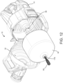
FIG. 12 is a perspective view of the drain cleaner ofFIG. 1 with the cover in the open position and a drum removed. -
FIG. 13 is a bottom perspective view of the drain cleaner ofFIG. 1 . -
FIG. 14 is a plan view of a system including the drain cleaner ofFIG. 1 and a wall organization system. -
FIG. 15 is a bottom perspective view of a drain cleaner according to another embodiment. -
FIG. 16 is a plan view of a system including the drain cleaner ofFIG. 15 and a wall organization system. - Before any embodiments of the invention are explained in detail, it is to be understood that the invention is not limited in its application to the details of construction and the arrangement of components set forth in the following description or illustrated in the following drawings. The invention is capable of other embodiments and of being practiced or of being carried out in various ways.
-
FIGS. 1-3 illustrate adrain cleaner 10. The illustrateddrain cleaner 10 may include ahousing 14, acover 18 coupled to thehousing 14, ahandle assembly 22, and anose assembly 26. As shown inFIG. 3 , thedrain cleaner 10 may also include amotor 30 and adrive mechanism 34 with anoutput shaft 38 positioned within thehousing 14. Theoutput shaft 38 may be coupled to adrum 42 to selectively rotate thedrum 42 about arotation axis 46 that extends through theoutput shaft 38 and the center of thenose assembly 26. Thedrain cleaner 10 may further include aflexible cable 50 that is stored within thedrum 42 and extends out of thenose assembly 26. Thecable 50 may be insertable into a drain, or other conduit, for cleaning the drain. In some embodiments, thecable 50 may include an auger head or other tool attachment at its distal end. - The
handle assembly 22 may extend rearwardly from thehousing 14. Thehandle assembly 22 may include agrip 54 that is configured to be grasped by a user for carrying and operating thedrain cleaner 10. Thehandle assembly 22 may support an actuator 58 (e.g., a trigger) adjacent thegrip 54. Theactuator 58 may be actuatable (e.g., depressible) by a user to selectively energize themotor 30 and, thereby, operate thedrain cleaner 10. The illustratedhandle assembly 22 may also include a battery receptacle 62 (FIG. 1 ) for receiving and supporting a battery pack, such as a power tool battery pack. Thebattery receptacle 62 may include terminals that electrically connect the battery pack to themotor 30 and theactuator 58. In other embodiments, thehandle assembly 22 may support or connect to a power cord to electrically connect themotor 30 to an AC power source. In the illustrated embodiment, thebattery receptacle 62 may be on a side of thehandle assembly 22 so that the battery pack is received in thebattery receptacle 62 in a direction orthogonal to therotation axis 46. In other embodiments, thebattery receptacle 62 may be positioned elsewhere on thehandle assembly 22 or drain cleaner 10. For example, thebattery receptacle 62 may be positioned on a bottom side of thehandle assembly 22 as shown inFIG. 15 . - As shown in
FIGS 1 and2 , the illustratedhandle assembly 22 may further include astand 66. In one embodiment, thestand 66 may be a base. Thestand 66 may be positioned generally beneath thehousing 14 and themotor 30. More particularly, thestand 66 may be positioned beneath a center of gravity of thedrain cleaner 10, which is principally defined by themotor 30, thedrive mechanism 34, thecable 50, and the battery pack (if present) of thedrain cleaner 10. Thestand 66 may include abottom surface 70 that is configured to engage and rest on a support surface 74 (e.g., a table, a workbench, a countertop, the floor, etc.). In one embodiment, thestand 66 may provide ease of use during operation. Thestand 66 may support thedrain cleaner 10 in an upright position (as illustrated inFIG. 3 ) with thenose assembly 26 spaced apart from thesupport surface 74. In some embodiments, such as the illustrated embodiment, a bottom surface of thestand 66 may define a plane that is parallel to therotation axis 46. - With reference to
FIG. 2A , thecover 18 may include anauxiliary handle 78 extending away from thecover 18. Theauxiliary handle 78 may be a removable auxiliary handle. Theauxiliary handle 78 may be coupled to atop portion 82 of thecover 18 using fasteners 86 (e.g., screws, bolts, etc.). Specifically, theauxiliary handle 78 may be coupled to thecover 18 using four fasteners 86 (i.e., two on each side of the auxiliary handle 78). Theauxiliary handle 78 may define a grip 87 and may include twoflanges 89 extending from the ends of the grip 87. The grip 87 may be a hollow cylindrical tube that a user can grasp. The grip 87 may have a length that extends perpendicular to therotation axis 46. Theflanges 89 may couple to opposing sides (i.e., a first side and a second side) of thecover 18. Eachflange 89 of theauxiliary handle 78 may include arib 88 with a geometric shape that corresponds to arecess 90 on thetop portion 82 of thecover 18. Therib 88 and therecess 90 may strengthen the connection between theauxiliary handle 78 and thecover 18 and allow for better support during operation by a user. Thefasteners 86 may be removed with a tool (e.g., screwdriver) to remove theauxiliary handle 78. In other embodiments, thefasteners 86 may be snaps, magnets, or other suitable fasteners that can be disconnected without a tool (e.g., may instead be disconnected by applying a suitable force). When theauxiliary handle 78 is coupled to thetop portion 82 of thecover 18, an opening 92 (FIG. 1 ) may be defined between theauxiliary handle 78 and thetop portion 82 of thecover 18 through which a user can insert their hand and grasp theauxiliary handle 78. Theauxiliary handle 78 may extend away from thecover 18 at an angle A (FIG. 3 ) relative to therotation axis 46. The angle A may be an oblique angle. In the illustrated embodiment, the angle A may be between 30 degrees and 60 degrees. In other embodiments, the angle A may be less than 30 degrees or more than 60 degrees. During operation, a user may place one hand on thegrip 54 and the other on theauxiliary handle 78 to support and stabilize thedrain cleaner 10 during transport or operation. - With reference to
FIG. 3 , thedrum 42 may be supported within thehousing 14 by aninner cone 94. Theinner cone 94 may be coupled to thedrive mechanism 34 such that rotation of themotor 30 is transmitted to thedrum 42 through thedrive mechanism 34 andinner cone 94. Friction between the inner surface of thedrum 42 and thecable 50 may cause thecable 50 to rotate or spin with thedrum 42. As thedrum 42 rotates, thecable 50 may also rotate. In some embodiments, thedrain cleaner 10 may include a feed mechanism, described below, that engages thecable 50 as it rotates, causing thecable 50 to be extended into the drain or retracted from the drain. Theillustrated drive mechanism 34 may include a gear train having, for example, planetary gear arrangements and theoutput shaft 38 that transmit rotation of themotor 30 to thedrum 42. In some embodiments, theinner cone 94 and thedrum 42 are integrally coupled together so that thedrum 42 and the inner cone 96 are removed together from the interior of thehousing 14. In some embodiments, thedrum 42 may be threadably coupled to theinner cone 94. In other embodiments, thedrum 42 may be coupled directly to thedrive mechanism 34 using other suitable means to transmit force (e.g., rotation) from thedrive mechanism 34 to thedrum 42. Additionally, in some embodiments, other suitable drive mechanisms may also or alternatively be employed. As will be discussed in more detail below, thedrum 42 may be removed from within thehousing 14 and replaced with another drum. - The illustrated
drum 42 may include a front portion or anose piece 98 that extends away from thedrum 42 and into thenose assembly 26. Thenose piece 98 may guide thecable 50 from thedrum 42 into thenose assembly 26. Thenose piece 98 of thedrum 42 may be positioned within abearing 100 when thecover 18 is in a closed position. Thebearing 100 may allow thedrum 42 to rotate relative to thenose assembly 26 during operation. Thenose assembly 26 may be positioned forward of thehousing 14 and may provide an additional grip for a user to hold thedrain cleaner 10 during operation. For example, a user can grasp thegrip 54 of thehandle assembly 22 with one hand to operate theactuator 58, and can grasp thenose assembly 26 with the other hand to help guide thedrain cleaner 10. In contrast to theauxiliary handle 78, the grip of thenose assembly 26 may have a length that is parallel to, or even coaxial with, therotation axis 46. As such, the grip 87 of theauxiliary handle 78 may be perpendicular to the grip of thenose assembly 26. - As illustrated in
FIGS. 1 and2 , thenose assembly 26 may also provide alock mechanism 102 for thedrain cleaner 10. In the illustrated embodiment, thelock mechanism 102 may include two spring clips 106 (FIG. 3 ) positioned within thenose assembly 26 on opposite sides of thenose piece 98 of thedrum 42. Thelock mechanism 102 may include twotabs 110 that extend from an interior of thenose assembly 26. Thelock mechanism 102 may be rotatable about therotation axis 46 from a locked position to an unlocked position. When thelock mechanism 102 is rotated to the locked position, a cam surface (not shown) may push the spring clips 106 inwardly to engage thecable 50. In this position, thecable 50 may be forced to rotate with thedrum 42. When thelock mechanism 102 is in the unlocked position, the spring clips 106 may be biased apart from each other and disengage thecable 50 so that thecable 50 can be fed out of or into thedrum 42. In some embodiments, thelock mechanism 102 may be biased away from the drum 42 (i.e., toward an unlocked position) by a spring or other biasing member. Although the illustratedlock mechanism 102 is rotated between locked and unlocked positions, in other embodiments, thelock mechanism 102 may slide axially between the locked and unlocked positions. - With continued reference to
FIGS. 1 and2 , thedrain cleaner 10 may further include acable feed mechanism 114 that helps guide and drive thecable 50 out of thedrum 42 and into a drain. Thecable feed mechanism 114 may be supported on the front end of thenose assembly 26. Thecable feed mechanism 114 may include a plurality ofrollers 118 that are moveable to engage thecable 50. Thecable feed mechanism 114 may be rotatable about therotation axis 46 between a manual feed position and an auto-feed position. When thecable feed mechanism 114 is in the manual feed position, therollers 118 do not engage thecable 50, allowing a user to manually pay out or push in thecable 50 from thedrum 42. As thecable feed mechanism 114 is moved from the manual feed position to the auto-feed position, therollers 118 may move radially inward to engage thecable 50. With thecable 50 engaged by therollers 118, when a user pushes thetrigger 58 and thedrum 42 rotates, therollers 118 may allow thecable 50 to be paid out automatically from thedrum 42 and into a drain or conduit. - With reference to
FIG. 4 , thedrum 42 may be removable from an interior of thehousing 14. Thecover 18 may be moveable from a closed position (FIG. 1 ) to an open position (FIG. 4 ) to allow access to thedrum 42 andcable 50 within thehousing 14. When in the closed position, thedrum 42 may be completely enclosed by thehousing 14 and thecover 18. As shown inFIGS. 5 and 6 , afirst latch mechanism 122 may be positioned on a first side of thehousing 14. Thefirst latch mechanism 122 may include anactuator 126 with awire bar 130 coupled thereto. Theactuator 126 may be pivotable from a first position (FIG. 5 ) to a second position (FIG. 6 ) to disengage thecover 18. Specifically, as theactuator 126 is pivoted, thewire bar 130 may move away from aclasp 134 on thecover 18 and the tension holding thecover 18 against thehousing 14 may be removed. In other embodiments, thedrain cleaner 10 may include other suitable latch mechanisms for thefirst latch mechanism 122. - With reference to
FIGS. 7 and 8 , thedrain cleaner 10 may also include asecond latch mechanism 138 on an opposite side of thehousing 14 from thefirst latch mechanism 122. Thesecond latch mechanism 138 may also be referred to as a hinge. Thesecond latch mechanism 138 may include anactuator 142 that is pivotable from a first position (FIG. 7 ) to a second position (FIG. 8 ) to release thecover 18 from thehousing 14. Theactuator 142 may be positioned within asupport 146 of thehousing 14 and may include abuckle 150 that corresponds to arib 154 on thecover 18. Theactuator 142 may be pivoted from the first position to the second position to release thecover 18 from thehousing 14. In other embodiments, thedrain cleaner 10 may include other suitable latch mechanisms for thesecond latch mechanism 138. - Moving to
FIG. 9 , thesupport 146 may define achannel 158 with atrack 162 that therib 154 of thecover 18 is moveable within. Once thesecond latch mechanism 138 is released, thecover 18 may slide forward to a pivoting position. Specifically, therib 154 on thecover 18 may include two protrusions 166 (FIG. 10 ) on opposite sides that engage the track 162 (e.g., oneprotrusion 166 may be positioned within an upper portion of thetrack 162 and theother protrusion 166 may be positioned within a lower portion of the track 162). As thecover 18 is slid to the pivoting position, theprotrusions 166 may slide along thetrack 162 until theprotrusions 166 reach a bulb-shaped end 170 (FIG. 11 ) of thetrack 162. Once theprotrusions 166 are within the bulb-shapedend 170, thecover 18 may be pivoted about anaxis 174 defined by theprotrusions 166 from the closed position to the open position to allow access to thedrum 42 andcable 50. That is, thecover 18 may first slide linearly away from thehousing 14, and then may pivot relative to thehousing 14. In the illustrated embodiment, theaxis 174 may be transverse to therotation axis 46. More particularly, theaxis 174 may be spaced apart from and perpendicular to therotation axis 46. - To remove the
drum 42 from within thehousing 14, a user may first release thefirst latch mechanism 122 by pivoting the actuator 126 from the first position to the second position, releasing thewire bar 130 from theclasp 134. Next, a user may release thesecond latch mechanism 138 by pivoting the actuator 142 from the first position to the second position, releasing thebuckle 150 from therib 154 of thecover 18. In other situations, the user may release thesecond latch mechanism 138 before thefirst latch mechanism 122, or may release both latchmechanisms cover 18 away from thehousing 14 until thecover 18 is in the pivoting position. As thecover 18 is pulled forward, thenose piece 98 of thedrum 42 may be released from thecover 18. Specifically, sliding thecover 18 axially along therotation axis 46 may allow thenose piece 98 to disengage thebearing 100 in thenose assembly 26 allowing thecover 18 to therefore pivot. Once in the pivoting position, a user may freely rotate thecover 18 about theaxis 174 to gain access to thedrum 42 andcable 50. As shown inFIG. 12 , in the open position, a user may remove thecable 50 through afront opening 178 of thedrum 42 or wind thecable 50 into thedrum 42. Additionally, while in the open position, the user may completely remove thedrum 42 from thehousing 14 by gently pulling thedrum 42 away from thehousing 14. As thedrum 42 is pulled away from thehousing 14, thedrum 42 and theinner cone 94 may be decoupled from theoutput shaft 38 of thedrive mechanism 34. While removed, thedrum 42 may be cleaned and returned to within the interior of thehousing 14. Alternatively, once thedrum 42 is removed, thedrum 42 may be exchanged with a different drum. For example, thedrum 42 may be exchanged with a newer drum and cable or for a drum with a different size/type of cable. - Providing a drain cleaner 10 with an
auxiliary handle 78 allows a user to easily maneuver and use thedrain cleaner 10 during operation. Thedrain cleaner 10 may include thegrip 54, theauxiliary handle 78, and thenose assembly 26 that a user may choose to position their hands on when handling thedrain cleaner 10. In addition, providing a drain cleaner 10 with a pivotablefront cover 18 allows easier access to thedrum 42 andcable 50 stored within thehousing 14. It should be noted that providing the drain cleaner 10 with first andsecond latch mechanisms cover 18 to an open position allows for easy access to the interior of thehousing 14 without needing an additional tool or the need to remove fasteners. - With reference to
FIGS. 13 and 14 , thedrain cleaner 10 may be supported by anorganization system 210. Theorganization system 210 may be a wall organization system, such as the one disclosed inU.S. Application Serial No. 17/396,282, filed August 6, 2021 organization system 210 may also be mounted to other suitable structures (e.g., cabinets, tables, etc.) or may be part of a storage box, tool box, or the like. Theorganization system 210 may include a mount orrail 214 having at least onecleat 218 that may be supported on a surface or a wall W. In the illustrated embodiment, thecleat 218 may be diamond-shaped. In other embodiments, thecleat 218 may have another shape (e.g., hexagonal, octagonal, etc.). As shown inFIG. 13 , thestand 66 of thehandle assembly 22 may include anopening 222 having a shape that corresponds to and receives thecleat 218. The engagement between thecleat 218 and theopening 222 of thedrain cleaner 10 may be a locking engagement, or a gravitational engagement similar to a French cleat. As such, thedrain cleaner 10 can be attached to the support surface (e.g., a wall W) through therail 214. Further, the engagement between thecleat 218 and theopening 222 may be referred to an over-the-diamond interface since theopening 222 receives thecleat 218. -
FIGS. 15 and 16 illustrate adrain cleaner 310 according to another embodiment. Thedrain cleaner 310 may be similar to thedrain cleaner 10 described above with like features being represented with like reference numbers. Thedrain cleaner 310 may include thehandle assembly 22, however, thehandle assembly 22 may include aflange portion 314 connecting thebattery receptacle 62 to thehousing 14. The flange portion may include a reduced width compared to the rest of thehandle assembly 22. As shown inFIG. 16 , the flange portion may be configured to engage the space between twocleats 218 of theorganization system 210. As such, thedrain cleaner 310 can be attached to the support surface (e.g., a wall W) through therail 214. The engagement between theflange portion 314 of thedrain cleaner 310 and thecleats 218 may be referred to as a between-the-diamond interface. - Although the invention has been described in detail with reference to certain preferred embodiments, variations and modifications exist within the scope and spirit of one or more independent aspects of the invention as described. Various features and advantages of the invention are set forth in the following claims.
- Representative features are set out in the following clauses, which stand alone or may be combined, in any combination, with or ore more features disclosed in the text and/or drawings of the specification.
- Clause 1. A drain cleaner comprising: a housing having an interior; a cover coupled to the housing over the interior; a nose assembly extending forwardly from the cover to define a first grip; a handle assembly extending rearwardly from the housing and including a second grip; a motor positioned within the housing, the motor defining a rotation axis; a drum positioned within the interior, the drum operable to be rotated by the motor relative to the housing; a flexible cable stored within the drum, the flexible cable configured to be extended out of the drum and into a drain; and an auxiliary handle extending from the cover and including a third grip, the auxiliary handle defining an opening between the third grip and the cover.
- Clause 2. The drain cleaner of clause 1, wherein the auxiliary handle is removably coupled to the cover.
-
Clause 3. The drain cleaner of clause 1, wherein the auxiliary handle extends away from the cover at an angle between 30 degrees and 60 degrees relative to the rotation axis. - Clause 4. The drain cleaner of clause 1, wherein the handle assembly includes a stand positioned beneath a center of gravity of the drain cleaner.
- Clause 5. The drain cleaner of clause 1, wherein the handle assembly includes a battery receptacle configured to receive a battery pack.
- Clause 6. The drain cleaner of clause 1, wherein the third grip has a length that extends perpendicular to the rotation axis.
- Clause 7. The drain cleaner of clause 1, wherein the auxiliary handle includes two flanges extending from ends of the third grip and coupled to opposing sides of the cover.
- Clause 8. The drain cleaner of clause 1, wherein the auxiliary handle includes a cylindrical tube.
- Clause 9. The drain cleaner of clause 1, wherein the cover is pivotably coupled to the housing and moveable between a closed position, in which the drum is enclosed within the interior, and an open position, in which the drum is accessible.
-
Clause 10. A drain cleaner comprising: a housing having an interior; a motor positioned within the housing, the motor defining a rotation axis; a drum positioned within the housing, the drum operable to be rotated by the motor relative to the housing; a flexible cable stored within the drum, the flexible cable configured to be extended out of the drum and into a drain; and a cover pivotably coupled to the housing, the cover pivotable between a closed position, in which the drum is enclosed within the interior, and an open position, in which the drum is accessible. - Clause 11. The drain cleaner of
clause 10, wherein when the cover is in the open position, the drum is removable from the interior of the housing. - Clause 12. The drain cleaner of
clause 10, wherein the drum is supported by an inner cone within the interior of the housing. - Clause 13. The drain cleaner of
clause 10, further comprising a first latch mechanism coupled to the housing and the cover, wherein the first latch mechanism is moveable from a first position, in which the cover is secured to the housing, and a second position, in which the cover is able to move between the open and closed positions. -
Clause 14. The drain cleaner of clause 13, further comprising a second latch mechanism coupled to the housing and the cover, wherein the second latch mechanism is moveable between a first position, in which, the cover is not pivotable relative to the housing, and a second position, in which the cover is pivotable between the open and closed positions. - Clause 15. The drain cleaner of
clause 14, wherein the first and second latch mechanisms are positioned on opposite sides of the housing from one another. - Clause 16. The drain cleaner of
clause 10, wherein the cover is pivotable about an axis that is transverse to the rotation axis. - Clause 17. A system comprising: an organization system including a cleat; and a drain cleaner including, a housing, a motor positioned within the housing, a handle assembly extending from the housing, the handle assembly including a stand with an opening, the opening configured to receive the cleat to connect the drain cleaner to the organization system, a drum positioned within the housing, the drum operable to be rotated by the motor relative to the housing, and a flexible cable stored within the drum, the flexible cable configured to be extended out of the drum and into a drain.
-
Clause 18. The system of clause 17, wherein the cleat is diamond shaped. - Clause 19. The system of clause 17, wherein the organization system includes a rail configured to be mounted to a wall, and wherein the cleat extends from the rail.
- Clause 20. The system of clause 17, wherein the cleat is a first cleat, and wherein the organization system further includes a second cleat.
Claims (15)
- A drain cleaner comprising:a housing having an interior;a cover coupled to the housing over the interior;a nose assembly extending forwardly from the cover to define a first grip;a handle assembly extending rearwardly from the housing and including a second grip;a motor positioned within the housing, the motor defining a rotation axis;a drum positioned within the interior, the drum operable to be rotated by the motor relative to the housing;a flexible cable stored within the drum, the flexible cable configured to be extended out of the drum and into a drain; andan auxiliary handle extending from the cover and including a third grip, the auxiliary handle defining an opening between the third grip and the cover.
- The drain cleaner of claim 1, wherein the auxiliary handle is removably coupled to the cover.
- The drain cleaner of claim 1, wherein the auxiliary handle extends away from the cover at an angle between 30 degrees and 60 degrees relative to the rotation axis.
- The drain cleaner of claim 1, wherein the handle assembly includes a stand positioned beneath a center of gravity of the drain cleaner.
- The drain cleaner of claim 1, wherein the handle assembly includes a battery receptacle configured to receive a battery pack.
- The drain cleaner of claim 1, wherein the third grip has a length that extends perpendicular to the rotation axis.
- The drain cleaner of claim 1, wherein the auxiliary handle includes two flanges extending from ends of the third grip and coupled to opposing sides of the cover.
- The drain cleaner of claim 1, wherein the auxiliary handle includes a cylindrical tube.
- The drain cleaner of claim 1, wherein the cover is pivotably coupled to the housing and moveable between a closed position, in which the drum is enclosed within the interior, and an open position, in which the drum is accessible.
- A drain cleaner comprising:a housing having an interior;a motor positioned within the housing, the motor defining a rotation axis;a drum positioned within the housing, the drum operable to be rotated by the motor relative to the housing;a flexible cable stored within the drum, the flexible cable configured to be extended out of the drum and into a drain; anda cover pivotably coupled to the housing, the cover pivotable between a closed position, in which the drum is enclosed within the interior, and an open position, in which the drum is accessible.
- The drain cleaner of claim 10, wherein when the cover is in the open position, the drum is removable from the interior of the housing.
- The drain cleaner of claim 10, wherein the drum is supported by an inner cone within the interior of the housing.
- The drain cleaner of claim 10, further comprising a first latch mechanism coupled to the housing and the cover, wherein the first latch mechanism is moveable from a first position, in which the cover is secured to the housing, and a second position, in which the cover is able to move between the open and closed positions.
- The drain cleaner of claim 13, further comprising a second latch mechanism coupled to the housing and the cover, wherein the second latch mechanism is moveable between a first position, in which, the cover is not pivotable relative to the housing, and a second position, in which the cover is pivotable between the open and closed positions.
- A system comprising:an organization system including a cleat; anda drain cleaner including,a housing,a motor positioned within the housing,a handle assembly extending from the housing, the handle assembly including a stand with an opening, the opening configured to receive the cleat to connect the drain cleaner to the organization system,a drum positioned within the housing, the drum operable to be rotated by the motor relative to the housing, anda flexible cable stored within the drum, the flexible cable configured to be extended out of the drum and into a drain.
Applications Claiming Priority (1)
| Application Number | Priority Date | Filing Date | Title |
|---|---|---|---|
| US18/471,928 US20250100028A1 (en) | 2023-09-21 | 2023-09-21 | Drain cleaner |
Publications (2)
| Publication Number | Publication Date |
|---|---|
| EP4528042A2 true EP4528042A2 (en) | 2025-03-26 |
| EP4528042A3 EP4528042A3 (en) | 2025-04-30 |
Family
ID=92582786
Family Applications (1)
| Application Number | Title | Priority Date | Filing Date |
|---|---|---|---|
| EP24196642.3A Pending EP4528042A3 (en) | 2023-09-21 | 2024-08-27 | Drain cleaner |
Country Status (3)
| Country | Link |
|---|---|
| US (1) | US20250100028A1 (en) |
| EP (1) | EP4528042A3 (en) |
| CN (1) | CN119663971A (en) |
Families Citing this family (1)
| Publication number | Priority date | Publication date | Assignee | Title |
|---|---|---|---|---|
| USD1135262S1 (en) * | 2025-07-09 | 2026-07-14 | Haitao Han | Pipe dredge |
Family Cites Families (9)
| Publication number | Priority date | Publication date | Assignee | Title |
|---|---|---|---|---|
| US4218802A (en) * | 1979-03-14 | 1980-08-26 | Emerson Electric Co. | Drain cleaning apparatus |
| US4763374A (en) * | 1987-12-07 | 1988-08-16 | Lewisan Products, Inc. | Powered drain cleaner |
| US4956889A (en) * | 1989-07-03 | 1990-09-18 | Emerson Electric Co. | Portable drain cleaning apparatus |
| WO2017100653A1 (en) * | 2015-12-09 | 2017-06-15 | Milwaukee Electric Tool Corporation | Drain cleaner |
| US10851868B2 (en) * | 2016-03-18 | 2020-12-01 | Ridge Tool Company | Motor dampener and drive train for plumbing tools |
| US10618086B2 (en) * | 2016-07-18 | 2020-04-14 | Milwaukee Electric Tool Corporation | Drain cleaner with feed handle |
| US11826896B2 (en) * | 2021-12-14 | 2023-11-28 | Matthias Keller | Power tool and battery support racks and methods of manufacturing |
| CN116397732B (en) * | 2023-03-28 | 2025-11-07 | 浙江普莱得电器股份有限公司 | Pipeline dredging machine |
| JP2024143630A (en) * | 2023-03-30 | 2024-10-11 | 株式会社マキタ | Angle impact tool |
-
2023
- 2023-09-21 US US18/471,928 patent/US20250100028A1/en active Pending
-
2024
- 2024-08-27 CN CN202411183040.4A patent/CN119663971A/en active Pending
- 2024-08-27 EP EP24196642.3A patent/EP4528042A3/en active Pending
Also Published As
| Publication number | Publication date |
|---|---|
| US20250100028A1 (en) | 2025-03-27 |
| EP4528042A3 (en) | 2025-04-30 |
| CN119663971A (en) | 2025-03-21 |
Similar Documents
| Publication | Publication Date | Title |
|---|---|---|
| EP3387194B1 (en) | Drain cleaner | |
| US11598081B2 (en) | Cable feed control mechanism for drain cleaner | |
| JP7229279B2 (en) | handheld surface cleaning device | |
| EP3756521B1 (en) | Cleaner holder | |
| US4660246A (en) | Versatile vacuum cleaning appliance | |
| CA2752431C (en) | Portable combined toolbox and vacuum cleaner | |
| US4644605A (en) | Stick vacuum cleaner | |
| US20250100028A1 (en) | Drain cleaner | |
| US20100308563A1 (en) | in or relating to trolleys | |
| US3958293A (en) | Pipe cleaning machine | |
| US11897533B2 (en) | Telescoping handle | |
| US20230151600A1 (en) | Sheathed flexible shaft drain cleaner | |
| AU2018202322B2 (en) | Drain cleaner with drum exchange mechanism | |
| USRE32751E (en) | Stick vacuum cleaner | |
| WO2025222320A1 (en) | Drain cleaners having a rotatable grip | |
| CN217938097U (en) | Cleaning equipment | |
| WO2025222321A1 (en) | Drain cleaners having axially slidable cable lock sleeve | |
| WO2025222316A1 (en) | Drain cleaners having a moveable support stand | |
| KR200330488Y1 (en) | Movable console for automobile |
Legal Events
| Date | Code | Title | Description |
|---|---|---|---|
| PUAI | Public reference made under article 153(3) epc to a published international application that has entered the european phase |
Free format text: ORIGINAL CODE: 0009012 |
|
| STAA | Information on the status of an ep patent application or granted ep patent |
Free format text: STATUS: THE APPLICATION HAS BEEN PUBLISHED |
|
| AK | Designated contracting states |
Kind code of ref document: A2 Designated state(s): AL AT BE BG CH CY CZ DE DK EE ES FI FR GB GR HR HU IE IS IT LI LT LU LV MC ME MK MT NL NO PL PT RO RS SE SI SK SM TR |
|
| PUAL | Search report despatched |
Free format text: ORIGINAL CODE: 0009013 |
|
| AK | Designated contracting states |
Kind code of ref document: A3 Designated state(s): AL AT BE BG CH CY CZ DE DK EE ES FI FR GB GR HR HU IE IS IT LI LT LU LV MC ME MK MT NL NO PL PT RO RS SE SI SK SM TR |
|
| RIC1 | Information provided on ipc code assigned before grant |
Ipc: E03C 1/302 20060101ALI20250326BHEP Ipc: B08B 9/045 20060101ALI20250326BHEP Ipc: E03F 9/00 20060101AFI20250326BHEP |
|
| STAA | Information on the status of an ep patent application or granted ep patent |
Free format text: STATUS: REQUEST FOR EXAMINATION WAS MADE |
|
| 17P | Request for examination filed |
Effective date: 20251024 |