EP4528034A1 - Sound attenuation submarine device and related sound attenuation process - Google Patents
Sound attenuation submarine device and related sound attenuation process Download PDFInfo
- Publication number
- EP4528034A1 EP4528034A1 EP23306540.8A EP23306540A EP4528034A1 EP 4528034 A1 EP4528034 A1 EP 4528034A1 EP 23306540 A EP23306540 A EP 23306540A EP 4528034 A1 EP4528034 A1 EP 4528034A1
- Authority
- EP
- European Patent Office
- Prior art keywords
- mattress
- seabed
- pile
- ballast
- layers
- Prior art date
- Legal status (The legal status is an assumption and is not a legal conclusion. Google has not performed a legal analysis and makes no representation as to the accuracy of the status listed.)
- Withdrawn
Links
Images




Classifications
-
- E—FIXED CONSTRUCTIONS
- E02—HYDRAULIC ENGINEERING; FOUNDATIONS; SOIL SHIFTING
- E02B—HYDRAULIC ENGINEERING
- E02B17/00—Artificial islands mounted on piles or like supports, e.g. platforms on raisable legs or offshore constructions; Construction methods therefor
- E02B17/0017—Means for protecting offshore constructions
-
- E—FIXED CONSTRUCTIONS
- E02—HYDRAULIC ENGINEERING; FOUNDATIONS; SOIL SHIFTING
- E02D—FOUNDATIONS; EXCAVATIONS; EMBANKMENTS; UNDERGROUND OR UNDERWATER STRUCTURES
- E02D13/00—Accessories for placing or removing piles or bulkheads, e.g. noise attenuating chambers
- E02D13/005—Sound absorbing accessories in piling
-
- E—FIXED CONSTRUCTIONS
- E02—HYDRAULIC ENGINEERING; FOUNDATIONS; SOIL SHIFTING
- E02B—HYDRAULIC ENGINEERING
- E02B17/00—Artificial islands mounted on piles or like supports, e.g. platforms on raisable legs or offshore constructions; Construction methods therefor
- E02B2017/0056—Platforms with supporting legs
- E02B2017/0065—Monopile structures
-
- E—FIXED CONSTRUCTIONS
- E02—HYDRAULIC ENGINEERING; FOUNDATIONS; SOIL SHIFTING
- E02B—HYDRAULIC ENGINEERING
- E02B17/00—Artificial islands mounted on piles or like supports, e.g. platforms on raisable legs or offshore constructions; Construction methods therefor
- E02B2017/0091—Offshore structures for wind turbines
-
- E—FIXED CONSTRUCTIONS
- E02—HYDRAULIC ENGINEERING; FOUNDATIONS; SOIL SHIFTING
- E02D—FOUNDATIONS; EXCAVATIONS; EMBANKMENTS; UNDERGROUND OR UNDERWATER STRUCTURES
- E02D27/00—Foundations as substructures
- E02D27/32—Foundations for special purposes
- E02D27/52—Submerged foundations, i.e. submerged in open water
- E02D27/525—Submerged foundations, i.e. submerged in open water using elements penetrating the underwater ground
Definitions
- the present invention relates to a sound attenuation submarine device.
- Offshore wind turbines make better use of wind energy to produce electricity using a turbine and an electrical generator.
- Offshore wind turbines are for example anchored to the seabed using one or more piles driven down vertically in the seabed. Each pile is for example initially placed on the seabed and then hammered down in the seabed, deeply enough to give sufficient stability to the wind turbine.
- This operation creates strong vibrations that propagate through the water and the seabed, gradually attenuating over hundreds of metres and/or kilometres. These vibrations, such as sound waves, disturb certain species of marine fauna, which are sensitive to some ranges of sound frequencies.
- One aim of the invention is therefore to propose a submarine device efficiently preventing sound propagation during the installation of piles on the seabed.
- the invention proposes a sound attenuation submarine device comprising a mat configured to be placed on the seabed around a pile to be driven down vertically in the seabed, the mat comprising one or more mattresses, each mattress comprising a plurality of superposed inflatable layers including one or more gas layers configured to be inflated with a filling gas and one or more ballast layers configured to be inflated with a ballast material having a density greater than water's density.
- the gas layers inflated with a filling gas limit sound propagation via the seabed.
- ballast layers configured to be inflated with a ballast material having a density greater than water's density, equilibrate and maintain the mattresses laid onto the seabed and further decrease sound propagation from the pile towards the seabed and/or from the seabed to the water.
- the submarine device according to the invention may have one or more of the following features, taken independently or in any technically acceptable combination thereof:
- the invention also concerns a sound attenuation process for the attenuation of sound during pushing down a pile vertically in the seabed, the sound attenuation process comprising laying a mat on the seabed around the pile, the mat comprising one or more mattress each comprising a plurality of superposed inflatable layers including one or more gas layers and one or more ballast layers, the sound attenuation process comprising laying the mattresses to form the mat around the pile and inflating each gas layer of each mattress with a filling gas and inflating each ballast layer of each mattress with a ballast material having a density greater than water's density.
- the sound attenuation process may have one or more of the following features, taken independently or in any technically acceptable combination thereof:
- Figure 1 illustrates a submarine device 1 configured to equip a pile 5 that is to be driven down into the seabed S.
- the pile 5 is for example a pile of an offshore wind turbine.
- the pile 5 extends along a longitudinal central axis A-A'.
- the longitudinal central axis A-A' is substantially vertical when the pile 5 is anchored to the seabed S.
- the pile 5 extends between a lower extremity 5A intended to be driven down in the seabed S, and an upper extremity, not visible on the drawings, which emerges above the free surface of water W or is below the free surface of water W.
- the pile 5 is a cylinder, for example with a parallelepiped or circular base.
- the pile 5 has a circular base centered on the longitudinal central axis A-A'.
- the pile 5 has a length for example comprised between 30 m and 150 m.
- the largest transverse dimension of the pile 5, taken horizontally, is for example comprised between 1 m and 15 m, preferably between 6 m and 14 m.
- the pile 5 is for example made of steel.
- the submarine device 1 comprises a mat 10 configured to be placed on the seabed S around the pile 5.
- the mat 10 is configured to extend circumferentially around the pile 5 with surrounding the pile 5, preferably completely.
- the mat 10 comprises one or more mattresses 15.
- the mat 10 comprises a plurality of mattresses 15 distributed around the pile 5 in order to cover a circular surface around the pile 5.
- the submarine device 1 is configurable at least in an undeployed configuration in which each mattress 15 is rolled, an intermediate position wherein each mattress 15 is unrolled, the mattresses 15 extending radially while being inclined relative to the seabed S, and a deployed configuration wherein each mattress 15 is laid on the seabed S, the mattresses 15 being angularly distributed around a mat central axis M-M' to form the mat 10 extending around the pile 5.
- the mat central axis M-M' coincides substantially with the longitudinal central axis A-A' when the mat 10 is laid around the pile 5 which is pushed down in the seabed S.
- radially means “along a radial direction R", the radial direction R being defined relatively to the mat central axis M-M', as illustrated on figure 1 .
- Each mattress 15 is for example in the shape of an angular sector of a disc. In the deployed configuration, the mattresses 15 form together the mat 10 with a disc shape.
- the mattresses 15 are preferably uniformly distributed around the mat central axis M-M'.
- the mat 10 comprises for example twelve mattresses 15. In other examples, the mat 10 comprises a different number of mattresses 15, for example four, five, six, seven, height, nine, ten, eleven or more than twelve mattresses 15.
- the mattresses 15 are preferably of identical shape.
- the mat 10 covers a circular surface of the seabed S, said circular surface having for example a diameter comprised between 30 m and 120 m, preferably between 80 m and 120 m.
- the mattresses 15 are positioned side by side on the seabed S, each mattress 15 being laid next to a neighboring mattress 15 either with a small gap between the two mattresses 15, or with a contact between the two mattresses 15, or even with a partial overlap.
- the mat 10 is configured to cover the circular surface of the seabed S as much as possible to limit the propagation of sound waves from the seabed S to the water W.
- the mattresses 15 have identical or similar structure and the structure of one of the mattresses 15 will be described in reference to Figure 3 .
- Each mattress 15 has a thickness, taken vertically when the mattresses 15 are laid on the seabed S, comprised between 40 cm and 60 cm.
- Each mattress 15 has a general quadrangular shape, with an inner edge 15A and an outer edge 15B, intended to form a section of respectively an inner edge and an outer edge of the mat 10, and two side edges 15C extending substantially radially in the deployed configuration of the mat 10 along corresponding side edges 15C of adjacent mattresses 15.
- each mattress 15 has a width, taken between the two side edges 15C, therefore along a direction perpendicular to the radial direction R bisecting the two side edges 15C, which increases from the inner edge 15A to the outer edge 15B.
- the length of the inner edge 15A is for example comprises between 0,5 m and 6 m, preferably between 4 m and 6 m and the length of the outer edge 15B is for example comprises between 5 m and 31, preferably between 21 m and 31 m.
- Each mattress 15 has a length, taken along the radial direction R between the inner edge 15A and the outer edge 15B, for example comprised between 32 m and 47 m.
- Each mattress 15 is multilayer.
- the filling gas 21 contains for example one gas or a mixture of gases.
- the filling gas 21 comprises for example oxygen, nitrogen, argon, neon, krypton, xenon, carbon dioxide, nitrogen protoxide, methane, hydrogen, helium or a mixture of at least two of them.
- the filling gas 21 is for example air, in particular dry air, optionally enriched with one or a plurality of its constituents, such as oxygen, nitrogen, argon, neon, krypton, xenon, carbon dioxide, nitrogen protoxide, methane, hydrogen, helium.
- each mattress 15 comprises or consists of one ballast layer 23 interposed between two gas layers 19 or one gas layer 19 interposed between two ballast layers 23.
- each mattress 15 comprises at least two gas layers 19.
- each mattress 15 comprises two gas layers 19 and one ballast layer 23 interposed between the two gas layers 19, the two gas layers 19 exhibiting thicknesses which are equal or preferably different.
- each mattress 15 comprises three inflatable layers, vertically superimposed one onto the other.
- the mattress 15 may have more than two gas layers 19 or less than two gas layers 19, and more than two ballast layers 23 or less than two ballast layers 23, each positioned relatively to the other in any way whatsoever.
- the gas layers 19 inflated with filling gas 21 help limiting sound propagation, which travels slowly in air.
- Ballast layers 23 weigh down the mattresses 15.
- the combination of one or more gas layers 19 with one or more ballast layers 23 with different densities helps trapping vibrations and limiting the transmission of vibrations from the seabed S to the water W.
- gas layers 19 with different thicknesses and/or ballast layers 23 with different thicknesses helps trapping vibrations and limiting the transmission of vibrations from the seabed S to the water W.
- the ballast material 25 is for example chosen among muds and/or clays, such as drilling mud, bentonite, or a suitable mud to increase high-frequency vibrations absorption as well in the ballast layers 23.
- the ballast material 25 is ballast into which some macro-beads of rubber are added.
- Each gas layer 19 comprises an envelope 27 comprising two opposed walls 27A, 27B connected by a plurality of connectors 28 distributed on the surface of the two walls 27A, 27B for delimiting a spacing between the two opposed walls 27A, 27B.
- the envelope 27 has for example a so-called drop stitch structure.
- the space between the two opposed walls 27A, 27B is to be filled with filling gas 21.
- the envelope 27 is for example made of relatively rigid fabrics.
- the envelope 27 is for example made from one or several synthetic polymers, for example one or several among polyvinylchloride, polychloroprene, polyurethane, polyethylene, polypropylene, copolymers of ethylene and propylene monomers, oligomers or polymers such as chlorosulfonated polyethylene such as Hypalon ® .
- the connectors 28 extend between the two opposed walls 27A, 27B. They provide rigidity to the gas layer 19 when the gas layer 19 is inflated and limit the flexibility of the gas layer 19 when the gas layer 19 is inflated.
- the opposed walls 27A, 27B are each monolayer, bilayer or multilayer. Providing opposed walls 27A, 27B with two or more layers increases the rigidity of the envelope.
- gas layers 19 of each mattress 15 have different thicknesses.
- One gas layer 19 of each mattress 15 has a thickness strictly greater than one or more other gas layer 19 of said mattress 15.
- Gas layers 19 with different thicknesses help trapping vibrations and limiting the transmission of vibration from the seabed S to the water W.
- one gas layer 19 has a thickness comprised between 5 cm and 15 cm, and the other gas layer 19 has a thickness strictly greater than that of the lower gas layer 19, for example comprised between 15 cm and 25 cm.
- one gas layer 19 has a thickness around 10 cm, and the other gas layer 19 has a thickness around 20 cm.
- the gas layer 19 with a lower thickness is the lower gas layer 19 and the gas layer 19 with the greater thickness is the upper gas layer 19.
- the configuration is opposite.
- each gas layer 19 may have a suitable thickness for optimizing sound attenuation effect.
- maximization of sound attenuation effect can be achieved when two separate gas layers have a different thickness.
- thickness ratio between two different gas layers 19 separated by a ballast layer 23 is preferably close to 1 + 5 / 2 .
- thickness ratio from 1,3 to 1,9 is suitable albeit not preferred, while thickness ratio from 1,5 to 1,7 is more desirable.
- Each ballast layer 23 comprises for example a plurality of tubes 30, which are attached together.
- the tubes 30 are preferably parallel.
- Each tube 30 is a cylinder with circular base, having a diameter for example comprised between 10 cm and 20 cm.
- Each ballast layer 23 comprises then a suitable number of tubes 30 aligned side to side along the entire width of the mattress 15.
- the ballast layer 23 comprises between 100 and 300 tubes 30.
- the tubes 30 are for example made of a rubber material such as polychloroprene, polyurethane, polyisoprene, silicone elastomer, ethylene propylene diene monomer rubber (EPDM), copolymers of ethylene or polyethylene such as chlorosulfonated polyethylene (such as Hypalon ® ), Hypalon covered with polychloroprene, for example optionally fiber reinforced polychloroprene (such as Neoprene TM ) wherein, when present, fiber reinforcement is woven or non-woven fabric, said fiber being natural or synthetic organic or inorganic fiber, such as glass fiber (synthetic inorganic fiber), ultra-high molecular weight polyethylene fiber (synthetic organic fiber, such as Dyneema ® ), flax or cellulose fiber (natural organic fiber), blue or white asbestos, sepiolite or wollastonite (natural inorganic fiber).
- a rubber material such as polychloroprene, polyurethane, poly
- Preferred fiber reinforcement material is polypropylene fiber or fabric, or ultra-high molecular weight polyethylene fiber such as Dyneema ® .
- the tubes 30 are for example attached together using a fastening device 32 which comprises or consists of for example an adhesive and/or mechanical fasteners.
- each ballast layer 23 is attached to each adjacent gas layers 19 using a fastening device which comprises or consists of for example an adhesive and/or mechanical fasteners.
- the submarine device 1 comprises an annular support 35 configured to be fitted around the pile 5, i.e. to be slided vertically along the pile 5.
- the annular support 35 When the annular support 35 is fitted onto the pile 5, the annular support 35 extends along the longitudinal central axis A-A'.
- submarine device 1 is able to slide along the pile 5 to keep the mat 10 laid onto the seabed S.
- the annular support 35 extends advantageously circumferentially all around the pile 5.
- the annular support 35 has an outer diameter for example comprised between 10 m and 20 m, for example equal to 15 m.
- the annular support 35 part of the submarine device 1 ensure the rotational mounting of the winding rollers 40 which are angularly distributed around the longitudinal central axis A-A'.
- Each winding roller 40 is configured for rolling and unrolling a respecting mattress 15 on said winding roller 40 in the undeployed and in the intermediate configurations of the submarine device 1.
- Each winding roller 40 extends along a respective roller axis B-B' which is for example parallel to the central axis A-A'.
- Each winding roller 40 has for example a diameter, without rolled mattresses, comprised between 1 m and 3 m. This diameter has to be compatible with the minimum radius of rolling of the mattress 15.
- Each winding roller 40 extends vertically over a length equal to or greater than the length of the outer edge 15B of each mattress 15.
- each winding roller 40 extends vertically over a length comprised between 10 m and 50 m, preferably between 32 m and 47 m.
- Each winding roller 40 is movable in rotation around its vertical axis B-B'.
- the submarine device 1 comprises a driving system (not shown on the drawings) comprising one or several motors coupled to the or each winding roller 40 for driving the winding rollers 40 in rotation such as to wind or unwind each mattress 15 from the corresponding winding roller 40.
- a driving system (not shown on the drawings) comprising one or several motors coupled to the or each winding roller 40 for driving the winding rollers 40 in rotation such as to wind or unwind each mattress 15 from the corresponding winding roller 40.
- the driving system comprises for example one respective motor for each winding roller 40.
- Each motor is for example a hydraulic motor.
- the number of winding rollers 40 on the annular support 35 is advantageously equal to the number of mattresses 15 of the mat 10.
- each mattress 15 is deflated and rolled onto a respective winding roller 40.
- each mattress 15 is rolled onto a winding roller 40 over 6 to 10 turns, depending on the length of the mattress 15 and on the diameter of the winding rollers 40.
- Figures 6 and 7 represent the submarine device 1 in the intermediate configuration.
- the mattresses 15 are unrolled with a substantially vertical orientation upon actuation of the driving system to drive each winding roller 40 in rotation around their rotation axes B-B'.
- Each mattress 15 is unrolled with resting on the seabed S via one side edge 15C of the mattresses 15 and being inclined relative to the seabed S, the other side edge 15C being away from the seabed S.
- the mattresses 15 While the mattresses 15 are being unrolled, they are at the same time inflated with the filling gas 21 and/or water.
- This step allows to better control the unrolling of the mattresses 15 and to make sure they deploy substantially radially with keeping in a vertical orientation.
- the submarine device 1 in order to assist the unwinding of the mattresses 15 from their respective winding rollers 40, the submarine device 1 comprises one or more deployment rings.
- the submarine device 1 comprises two deployment rings.
- the submarine device 1 comprises one upper deployment ring 44A and one lower deployment ring 44B.
- Each deployment ring 44A, 44B is for instance made by a reinforced fabric.
- Each deployment ring 44A, 44B is attached to each mattress 15, for example by means of fabric strips, not represented on the drawings.
- the lower deployment ring 44B is attached to a lower attachment point 48 of each mattress 15.
- the lower attachment point 48 of each mattress 15 is located lower than the upper attachment point 46 of said mattress 15 in the intermediate configuration.
- the lower attachment point 48 is adjacent to the junction between the outer edge 15B of the mattress 15 and the side edge 15C of the mattress 15 which rests on the seabed S in the intermediate configuration of the submarine device 1.
- Each deployment ring 44A, 44B is flexible.
- each deployment rings 44A, 44B to be grouped close to the annular support 35 in the undeployed configuration and extended away from the annular support 35 when the mattresses 15 are unrolled in the intermediate configuration.
- one or each deployment ring 44A, 44B is inflatable.
- the deployment rings 44A, 44B may be inflated with a gas, water, or ballast material 25.
- the deployment rings 44A, 44B may for example be inflated with any inert gas or mixture of gas, and for example with the filling gas 21. Gases containing halogen are not desirable.
- Each mattress 15 is coupled to the corresponding winding roller 40.
- Figure 8 is a zoomed view of a coupling between the mattresses 15 and the corresponding winding rollers 40.
- Each mattress 15 is fixed to a respective winding roller 40 by a connection 50.
- each mattress 15 is fixed by the inner edge 15A to a lower part of a respective winding roller 40.
- connection 50 is preferably a flexible connection 50, for example a flexible cable, line or strip.
- the flexible connection 50 does not impede the rotation of the mattresses 15 when they go from the intermediate configuration to the deployed configuration, as it will be described later.
- the submarine device 1 comprises a central annular carpet 55 configured to be laid on the seabed S around the pile 5 and to cover an annular gap between the mat 10 and the pile 5.
- the annular carpet 55 is for example a monolayer carpet, made of a polyurethane foam or polystyrene.
- the annular carpet 55 may be inflatable or solid.
- the annular carpet 55 may for instance be inflated with gas (in particular filling gas), water or ballast material 25.
- the annular carpet 55 is connected to the annular support 35. In other words, the annular carpet 55 moves with the annular support 35 during the translational movements of the annular support 35 along the pile 5.
- the annular carpet 55 allows increasing the sound attenuation, by effectively covering a maximal seabed surface.
- Figure 9 shows the transition between the intermediate configuration and the deployed configuration of the submarine device 1, the mattresses 15 being gradually inclined towards the seabed S until they completely lay on the seabed S.
- the deployment rings 44A, 44B hold the mattresses 15 together during their deployment and makes sure they will all incline the same side, as it is illustrated on Figure 8 .
- Each mattress 15 is initially rolled onto a respective winding roller 40.
- the sound attenuation process comprises a first step of laying the mat 10 on the seabed S around the pile 5, while laying the mattresses 15 to form the mat 10 around the pile 5.
- each mattress 15 is unrolled form the winding roller 40 while extending radially and is then inclined relative to the seabed S.
- This step is for example done upon activation of the hydraulic motors to drive each winding roller 40 in rotation around its respective rotation axis B-B'.
- gas preferably filling gas 21, and water are injected in the gas layers 19 to insure a correct unrolling of the mattresses 15, as previously described.
- the submarine device 1 comprises one or more manifolds for injecting fluids into one or more layers of each mattress 15.
- the one or more manifolds are for example configured for injecting to inject filling gas 21 and/or water into each gas layer 19 and/or for injecting water and/or ballast material 25 in each ballast layer 23 of the mattress 15.
- the one or more manifolds are for example fluidly connect to a fluid injection system, not represented, configured to provide filling gas 21, ballast material 25 and/or water.
- This system is for example located on the annular support 35.
- the one or more manifolds are for example fluidly connect to a fluid injection system via multi-fluid quick connector adapted for a rapid connection-disconnection between the submarine device 1 and an umbilical connected to an installation vessel.
- Another umbilical is for example dedicated to electrical power, control and signals provided by sensors (pressure, force, position, etc.) arranged in the submarine device 1.
- a gas layer 19 of a mattress 15 is illustrated in the intermediate configuration of the submarine device 1.
- the submarine device 1 comprises a manifold for filling the gas layer 19, for example with filling gas 21 and/or water.
- Each manifold has one or more air inlets 65, one or more air outlets 67, one or more water inlets 69 and one or more water outlets 71, each being connected to the gas layers 19.
- each gas layer 19 is connected to an upper air inlet 65, a lower water inlet 69, an upper air outlet 71 and a lower water outlet 71.
- the air outlet 67 and the water outlet 71 are for example outlet valves.
- the relative injected air/water proportion is evolving during the unrolling of the mattresses 15, in a suitable way for deploying each mattress 15 vertically.
- the amount of injected filling gas 21 and water shall compensate the weight of the envelopes 27 of the gas layers 19, in order to make the mattress 15 neutral in water.
- each ballast layer 23 of each mattress 15 is inflated with water during the unrolling of said mattress 15.
- the submarine device 1 comprises a manifold for filling the ballast layer 23 with ballast material 25 or water.
- Each unrolled mattress 15, having the gas layers 19 inflated with air and/or water, is then laid on the seabed S to form the mat 10 comprising the mattresses 15 distributed around the pile 5.
- the laying step is achieved by injection of the ballast material 25 inside the ballast layers 23.
- the mattresses 15, unrolled vertically, are inclined relative to the seabed S, for example using the upper deployment ring 44A and/or the lower deployment ring 44B.
- the upper deployment ring 44A and/or the lower deployment ring 44B are for example filled with gas (in particular filling gas), water and/or ballast material 25 and cause each mattress 15 to incline, in the same direction, towards the seabed S.
- gas in particular filling gas
- each mattress 15 The injection of the ballast material 25 in each mattress 15 is operated when the mattresses 15 are inclined relative to the seabed S such that the ballast material 25 fills a lower part of the mattresses 15 and gradually rises into the mattresses 15 such as to gradually lay the mattresses 15 on the seabed S.
- a ballast layer 23 of a mattress 15 is represented in the intermediate configuration of the submarine device 1.
- the tubes 30 extend radially and horizontally to form the ballast layer 23.
- the submarine device 1 comprises at least one manifold to inject the ballast material 25 into the ballast layers 23.
- Each manifold has one or more ballast material inlets 73, one or more ballast material outlets 75, one or more water inlets 77 and one or more water outlets 79, each being connected to the ballast layer 23.
- each ballast layer 23 is connected to a lower ballast material inlet 73, an upper ballast material outlet 75, an upper water inlet 77 and a lower water outlet 79.
- one manifold may inject the ballast material 25 inside one or several tubes 30 simultaneously.
- the tubes 30 extend between an inlet manifold for injecting the ballast material 25 in the tubes 30 and an outlet manifold for retrieving the ballast material from the tubes 30.
- each tube 30 is connected to several ballast material inlets 73.
- the tubes 30 may have a front ballast material inlet, a rear ballast material inlet, opposite the front one along the radial direction R, and/or several successive ballast material inlets disposed along the tube 30.
- ballast material 25 is for example done by pushing out the water towards the water outlet 79.
- the sound attenuation process is effective and the pile 5 can be driven into the seabed S without disturbing the marine fauna.
- the submarine device 1 can be taken off the pile 5 by sliding it along the pile 5 towards the water surface.
- This process starts with emptying the inflatable layers 17 of each mattress 15.
- the ballast material 25 is first pushed out of the ballast layers 23, exiting by the ballast outlets 75.
- ballast material 25 from the tubes 30 is achieved for instance by injecting water, in particular seawater, from the water inlet 77 into the ballast layer 23 to push out the ballast material 25 towards the ballast material outlet 75.
- a fluidic equipment for example comprising an aspiration device, not represented, may be used to take the ballast material 25 off the ballast layers 23.
- the submarine device 1 comprises, for each mattress 15, a pair of pressing rollers 90 defining between them a slit, the mattress 15 passing through the slit when unrolling from the winding roller 40 or rolling onto the winding roller 40.
- Each pair of pressing rollers 90 is for example mounted on the annular support 35 adjacent to the corresponding winding rollers 40, such that the mattress 15 passes between the pressing rollers 90 upon rolling the mattress 15 on the winding roller 40, the mattress 15 being pressed between the pressing roller 90 to empty the gas layers 19 and the ballast layers 23.
- the pressing rollers 90 are for example driven in rotation by the same driving system as the winding rollers 40.
- the width of the slit defined between two pressing rollers 90A, 90B is for example comprised between 3 cm and 5 cm, depending the thickness of the layers of the mattresses 15.
- a pressing force exerted by the rollers 90A, 90B onto the mattress 15 passing between the rollers 90A, 90B is for example adjusted using one or several springs urging the rollers 90A, 90B one towards the other.
- the width of the slit is strictly lower than the thickness of the mattresses 15 when at least one inflatable layer is inflated with filling gas 21, water, or ballast material 25, so that the passage between the two pressing rollers 90A, 90B presses the mattress 15 and empties the or each inflatable layer filled with filling gas 21, water or ballast material 25.
- each mattress 15 passes through the slit and is pressed between the two pressing rollers 90A, 90B before being rolled onto the respective winding roller 40.
- each mattress 15 passes through the slit and is pressed between the pressing rollers 90 and the winding roller 40 while being rolled onto the winding roller 40.
- the submarine device 1 comprises an air curtain creation system to increase even more the sound attenuation efficiency of the submarine device 1 while pushing down the pile 5.
- the air curtain creation system is located onto the lower deployment ring 44B.
- some inflatable elements are added to the annular support 35, for example fixed to the winding rollers 40, in order to increase even more the sound attenuation efficiency of the submarine device 1.
- the submarine device 1 according to the invention has many advantages.
- the mattresses 15 designed with several gas layers 19 and ballast layers 23 are suitable for accommodating thermal expansion phenomena.
- the mattresses configuration with one ballast layer interposed between two gas layers helps diminishing the mechanical deformation engendered by the relative forces and pressure applied to the submarine device 1 when the mat is laid on the seabed S.
- the submarine device 1 is easily installed and removed from the pile 5.
Landscapes
- Engineering & Computer Science (AREA)
- General Engineering & Computer Science (AREA)
- Civil Engineering (AREA)
- Structural Engineering (AREA)
- Life Sciences & Earth Sciences (AREA)
- General Life Sciences & Earth Sciences (AREA)
- Mining & Mineral Resources (AREA)
- Paleontology (AREA)
- Mechanical Engineering (AREA)
- Mattresses And Other Support Structures For Chairs And Beds (AREA)
Abstract
The sound attenuation submarine device (1) comprises a mat (10) configured to be placed on the seabed (S) around a pile (5) to be driven down vertically in the seabed (S), the mat (10) comprising one or more mattresses (15), each mattress (15) comprising a plurality of superposed inflatable layers (19, 23) including one or more gas layers (19) configured to be inflated with a filling gas (21) and one or more ballast layers (23) configured to be inflated with a ballast material (25) having a density greater than water's density.
Description
- The present invention relates to a sound attenuation submarine device.
- Considering the current environmental crisis, the use of renewable energies instead of fossil fuels is nowadays in full expansion.
- To this end, a large number of wind turbines are installed, both onshore and offshore.
- Offshore wind turbines make better use of wind energy to produce electricity using a turbine and an electrical generator.
- Offshore wind turbines are for example anchored to the seabed using one or more piles driven down vertically in the seabed. Each pile is for example initially placed on the seabed and then hammered down in the seabed, deeply enough to give sufficient stability to the wind turbine.
- This operation creates strong vibrations that propagate through the water and the seabed, gradually attenuating over hundreds of metres and/or kilometres. These vibrations, such as sound waves, disturb certain species of marine fauna, which are sensitive to some ranges of sound frequencies.
- In order to protect the marine environment, it is therefore necessary to reduce the intensity and/or propagation of the sound generated during the installation of wind turbines.
- To this end, it is possible to create curtains of air bubbles rising from the seabed towards the surface to act as a barrier to the propagation of sound in the water. These air curtains are created by one or more specific devices arranged all around the pile or piles of the wind turbine. This solution reduces a large proportion of the vibrations, particularly high-frequency vibrations, which propagate rapidly in the water.
- However, it does not reduce the propagation of low-frequency vibrations, which can propagate in the seabed with bypassing the air curtain and then propagate into water.
- One aim of the invention is therefore to propose a submarine device efficiently preventing sound propagation during the installation of piles on the seabed.
- To this aim, the invention proposes a sound attenuation submarine device comprising a mat configured to be placed on the seabed around a pile to be driven down vertically in the seabed, the mat comprising one or more mattresses, each mattress comprising a plurality of superposed inflatable layers including one or more gas layers configured to be inflated with a filling gas and one or more ballast layers configured to be inflated with a ballast material having a density greater than water's density.
- The gas layers inflated with a filling gas limit sound propagation via the seabed.
- Moreover, ballast layers configured to be inflated with a ballast material having a density greater than water's density, equilibrate and maintain the mattresses laid onto the seabed and further decrease sound propagation from the pile towards the seabed and/or from the seabed to the water.
- The submarine device according to the invention may have one or more of the following features, taken independently or in any technically acceptable combination thereof:
- each mattress comprises or consists of one ballast layer interposed between two gas layers or one gas layer interposed between two ballast layers;
- each mattress comprises at least two gas layers;
- each mattress comprises at least two gas layers of different thicknesses;
- each ballast layer is formed of a plurality of tubes which are preferably parallel;
- the tubes extend between an inlet manifold for injecting ballast material in the tubes and an outlet manifold for retrieving ballast material from the tubes;
- each gas layer comprises an envelope comprising two opposed walls connected by a plurality of connectors distributed on the surface of the two walls for delimiting a spacing between the two opposed walls;
- the submarine device is configurable at least in an undeployed configuration wherein each mattress is rolled, an intermediate position wherein each mattress is unrolled, the mattresses extending radially while being inclined relative to the seabed, and a deployed configuration wherein each mattress is laid on the seabed, the mattresses being angularly distributed to form the mat extending around the pile;
- the submarine device comprises an annular support intended to be fitted around the pile, the annular support comprising winding rollers angularly distributed on the annular support, each mattress being deflated and rolled onto a respective winding roller in the undeployed configuration;
- the submarine device comprises one or more deployment ring, each deployment ring being attached to each mattress, each deployment ring being preferably inflatable;
- the submarine device comprises two deployment rings, one being attached to a lower attachment point of each mattress and the other being attached to an upper attachment point of each mattress, the lower attachment point of each mattress being located lower than the upper attachment point of said mattress in the intermediate configuration;
- the submarine device comprises a central annular carpet configured to be laid on the seabed around the pile and to cover an annular gap between the mat and the pile.
- According to another aspect, the invention also concerns a sound attenuation process for the attenuation of sound during pushing down a pile vertically in the seabed, the sound attenuation process comprising laying a mat on the seabed around the pile, the mat comprising one or more mattress each comprising a plurality of superposed inflatable layers including one or more gas layers and one or more ballast layers, the sound attenuation process comprising laying the mattresses to form the mat around the pile and inflating each gas layer of each mattress with a filling gas and inflating each ballast layer of each mattress with a ballast material having a density greater than water's density.
- The sound attenuation process may have one or more of the following features, taken independently or in any technically acceptable combination thereof:
- each mattress is initially rolled onto a respective winding roller, each mattress is unrolled form the winding roller while extending radially and being inclined relative to the seabed and then laid on the seabed to form the mat comprising the mattresses distributed around the pile;
- the injection of ballast material in each mattress is operated when the mattress is inclined relative to the seabed such that the ballast material fills a lower part of the mattress and gradually rises into the mattress such as to gradually lay the mattress on the seabed.
- Further features and advantages of the invention will be apparent from the description given below, by way of indication and by no means limitative, with reference to the appended figures, among which:
-
Figure 1 is a top-view of a submarine device in a deployed configuration, -
Figure 2 is a side-view of the submarine device ofFigure 1 in the deployed configuration, -
Figure 3 is a cross-sectional view of a mattress of the submarine device ofFigure 1 , taken in a vertical plane, -
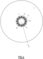
Figure 4 is a top-view of the submarine device ofFigure 1 in an undeployed configuration, -
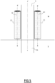
Figure 5 is a side-view of the submarine device ofFigure 4 in the undeployed configuration, -
Figure 6 is a top-view of the submarine device ofFigure 1 in an intermediate configuration, -
Figure 7 is a side-view of the submarine device ofFigure 6 in the intermediate configuration, -
Figure 8 is a side-view of the submarine device ofFigure 6 in the intermediate configuration, zoomed on the fixation means between the mattresses and the annular support, -
Figure 9 is a perspective view of the submarine device ofFigure 6 in the intermediate configuration, -
Figure 10 is a side view of the submarine device ofFigure 1 in the intermediate configuration, zoomed on the air/water injection means in the mattresses, -
Figure 11 is a side view of the submarine device ofFigure 1 in the intermediate configuration, zoomed on the ballast material injection means in the mattresses, and -
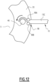
Figure 12 is a top view of the submarine device ofFigure 1 , zoomed on the winding rollers of the annular support. -
Figure 1 illustrates asubmarine device 1 configured to equip apile 5 that is to be driven down into the seabed S. - The
pile 5 is for example a pile of an offshore wind turbine. - The
submarine device 1 is not limited to use with a pile for a wind turbine. In variants, thepile 5 may be a pile for any infrastructure anchored to the seabed S, such as an oil platform for example. - The
pile 5 extends along a longitudinal central axis A-A'. The longitudinal central axis A-A' is substantially vertical when thepile 5 is anchored to the seabed S. - In the following, the terms "vertical", "horizontal", "lower" and "upper" refer to the position of the
pile 5 anchored to the seabed S with the longitudinal central axis A-A' oriented vertically. - The
pile 5 extends between alower extremity 5A intended to be driven down in the seabed S, and an upper extremity, not visible on the drawings, which emerges above the free surface of water W or is below the free surface of water W. - The
pile 5 is a cylinder, for example with a parallelepiped or circular base. - In some examples, the
pile 5 has a circular base centered on the longitudinal central axis A-A'. - The
pile 5 has a length for example comprised between 30 m and 150 m. - The largest transverse dimension of the
pile 5, taken horizontally, is for example comprised between 1 m and 15 m, preferably between 6 m and 14 m. - The
pile 5 is for example made of steel. - The
submarine device 1 comprises amat 10 configured to be placed on the seabed S around thepile 5. Themat 10 is configured to extend circumferentially around thepile 5 with surrounding thepile 5, preferably completely. - The
mat 10 comprises one ormore mattresses 15. - In some examples, the
mat 10 comprises a plurality ofmattresses 15 distributed around thepile 5 in order to cover a circular surface around thepile 5. - The
submarine device 1 is configurable at least in an undeployed configuration in which eachmattress 15 is rolled, an intermediate position wherein eachmattress 15 is unrolled, themattresses 15 extending radially while being inclined relative to the seabed S, and a deployed configuration wherein eachmattress 15 is laid on the seabed S, themattresses 15 being angularly distributed around a mat central axis M-M' to form themat 10 extending around thepile 5. - The mat central axis M-M' coincides substantially with the longitudinal central axis A-A' when the
mat 10 is laid around thepile 5 which is pushed down in the seabed S. - In the following "radially", means "along a radial direction R", the radial direction R being defined relatively to the mat central axis M-M', as illustrated on
figure 1 . - Each
mattress 15 is for example in the shape of an angular sector of a disc. In the deployed configuration, themattresses 15 form together themat 10 with a disc shape. - The
mattresses 15 are preferably uniformly distributed around the mat central axis M-M'. - The
mat 10 comprises for example twelvemattresses 15. In other examples, themat 10 comprises a different number ofmattresses 15, for example four, five, six, seven, height, nine, ten, eleven or more than twelvemattresses 15. - The
mattresses 15 are preferably of identical shape. - As illustrated on
Figures 1 and2 , in the deployed configuration of thesubmarine device 1, themat 10 covers a circular surface of the seabed S, said circular surface having for example a diameter comprised between 30 m and 120 m, preferably between 80 m and 120 m. - In the deployed configuration, the
mattresses 15 are positioned side by side on the seabed S, eachmattress 15 being laid next to a neighboringmattress 15 either with a small gap between the twomattresses 15, or with a contact between the twomattresses 15, or even with a partial overlap. - The
mat 10 is configured to cover the circular surface of the seabed S as much as possible to limit the propagation of sound waves from the seabed S to the water W. - The
mattresses 15 have identical or similar structure and the structure of one of themattresses 15 will be described in reference toFigure 3 . - Each
mattress 15 has a thickness, taken vertically when themattresses 15 are laid on the seabed S, comprised between 40 cm and 60 cm. - Each
mattress 15 has a general quadrangular shape, with aninner edge 15A and anouter edge 15B, intended to form a section of respectively an inner edge and an outer edge of themat 10, and twoside edges 15C extending substantially radially in the deployed configuration of themat 10 along corresponding side edges 15C ofadjacent mattresses 15. - In the deployed configuration, each
mattress 15 has a width, taken between the twoside edges 15C, therefore along a direction perpendicular to the radial direction R bisecting the twoside edges 15C, which increases from theinner edge 15A to theouter edge 15B. - The length of the
inner edge 15A is for example comprises between 0,5 m and 6 m, preferably between 4 m and 6 m and the length of theouter edge 15B is for example comprises between 5 m and 31, preferably between 21 m and 31 m. - Each
mattress 15 has a length, taken along the radial direction R between theinner edge 15A and theouter edge 15B, for example comprised between 32 m and 47 m. - Each
mattress 15 is multilayer. - Each
mattress 15 comprises a plurality of superposed inflatable layers including one ormore gas layers 19 configured to be inflated with a fillinggas 21 and one or more ballast layers 23 configured to be inflated with aballast material 25 having a density greater than water density. - The filling
gas 21 contains for example one gas or a mixture of gases. - The filling
gas 21 comprises for example oxygen, nitrogen, argon, neon, krypton, xenon, carbon dioxide, nitrogen protoxide, methane, hydrogen, helium or a mixture of at least two of them. - The filling
gas 21 is for example air, in particular dry air, optionally enriched with one or a plurality of its constituents, such as oxygen, nitrogen, argon, neon, krypton, xenon, carbon dioxide, nitrogen protoxide, methane, hydrogen, helium. - For example, each
mattress 15 comprises or consists of oneballast layer 23 interposed between twogas layers 19 or onegas layer 19 interposed between two ballast layers 23. - Preferably, each
mattress 15 comprises at least two gas layers 19. - In some examples, as illustrated on
Figure 3 , eachmattress 15 comprises twogas layers 19 and oneballast layer 23 interposed between the twogas layers 19, the twogas layers 19 exhibiting thicknesses which are equal or preferably different. In such examples, eachmattress 15 comprises three inflatable layers, vertically superimposed one onto the other. - In other examples, the
mattress 15 may have more than twogas layers 19 or less than twogas layers 19, and more than twoballast layers 23 or less than twoballast layers 23, each positioned relatively to the other in any way whatsoever. - The gas layers 19 inflated with filling
gas 21 help limiting sound propagation, which travels slowly in air. - Ballast layers 23 weigh down the
mattresses 15. - The combination of one or
more gas layers 19 with one or more ballast layers 23 with different densities helps trapping vibrations and limiting the transmission of vibrations from the seabed S to the water W. - The provision of
gas layers 19 with different thicknesses and/orballast layers 23 with different thicknesses helps trapping vibrations and limiting the transmission of vibrations from the seabed S to the water W. - The
ballast material 25 is for example chosen among muds and/or clays, such as drilling mud, bentonite, or a suitable mud to increase high-frequency vibrations absorption as well in the ballast layers 23. - In some examples, the
ballast material 25 is ballast into which some macro-beads of rubber are added. - Each
gas layer 19 comprises anenvelope 27 comprising twoopposed walls connectors 28 distributed on the surface of the twowalls opposed walls envelope 27 has for example a so-called drop stitch structure. - The space between the two
opposed walls gas 21. - The
envelope 27 is for example made of relatively rigid fabrics. Theenvelope 27 is for example made from one or several synthetic polymers, for example one or several among polyvinylchloride, polychloroprene, polyurethane, polyethylene, polypropylene, copolymers of ethylene and propylene monomers, oligomers or polymers such as chlorosulfonated polyethylene such as Hypalon®. - The
connectors 28 extend between the twoopposed walls gas layer 19 when thegas layer 19 is inflated and limit the flexibility of thegas layer 19 when thegas layer 19 is inflated. - The
opposed walls opposed walls - In some examples, gas layers 19 of each
mattress 15 have different thicknesses. Onegas layer 19 of eachmattress 15 has a thickness strictly greater than one or moreother gas layer 19 of saidmattress 15. - Gas layers 19 with different thicknesses help trapping vibrations and limiting the transmission of vibration from the seabed S to the water W.
- In some examples, as illustrated on
Figure 3 , onegas layer 19 has a thickness comprised between 5 cm and 15 cm, and theother gas layer 19 has a thickness strictly greater than that of thelower gas layer 19, for example comprised between 15 cm and 25 cm. - In particular, one
gas layer 19 has a thickness around 10 cm, and theother gas layer 19 has a thickness around 20 cm. - In some examples, the
gas layer 19 with a lower thickness is thelower gas layer 19 and thegas layer 19 with the greater thickness is theupper gas layer 19. In a variant, the configuration is opposite. - In a more general way, each
gas layer 19 may have a suitable thickness for optimizing sound attenuation effect. - In a more specific way, maximization of sound attenuation effect can be achieved when two separate gas layers have a different thickness.
- In this respect, thickness ratio between two
different gas layers 19 separated by aballast layer 23 is preferably close to
- Each
ballast layer 23 comprises for example a plurality oftubes 30, which are attached together. - The
tubes 30 are preferably parallel. - Each
tube 30 is a cylinder with circular base, having a diameter for example comprised between 10 cm and 20 cm. - Each
ballast layer 23 comprises then a suitable number oftubes 30 aligned side to side along the entire width of themattress 15. - For example, the
ballast layer 23 comprises between 100 and 300tubes 30. - The
tubes 30 are for example made of a rubber material such as polychloroprene, polyurethane, polyisoprene, silicone elastomer, ethylene propylene diene monomer rubber (EPDM), copolymers of ethylene or polyethylene such as chlorosulfonated polyethylene (such as Hypalon®), Hypalon covered with polychloroprene, for example optionally fiber reinforced polychloroprene (such as Neoprene™) wherein, when present, fiber reinforcement is woven or non-woven fabric, said fiber being natural or synthetic organic or inorganic fiber, such as glass fiber (synthetic inorganic fiber), ultra-high molecular weight polyethylene fiber (synthetic organic fiber, such as Dyneema®), flax or cellulose fiber (natural organic fiber), blue or white asbestos, sepiolite or wollastonite (natural inorganic fiber). - Preferred fiber reinforcement material is polypropylene fiber or fabric, or ultra-high molecular weight polyethylene fiber such as Dyneema®.
- The
tubes 30 are for example attached together using afastening device 32 which comprises or consists of for example an adhesive and/or mechanical fasteners. - Similarly, the
tubes 30 of eachballast layer 23 are attached to each adjacent gas layers 19 using a fastening device which comprises or consists of for example an adhesive and/or mechanical fasteners. - The undeployed configuration of the
submarine device 1 will now be described, with reference toFigures 4 and5 . - The
submarine device 1 comprises anannular support 35 configured to be fitted around thepile 5, i.e. to be slided vertically along thepile 5. - When the
annular support 35 is fitted onto thepile 5, theannular support 35 extends along the longitudinal central axis A-A'. - When the
annular support 35 is fitted on thepile 5 and thepile 5 is driven down in the seabed S,submarine device 1 is able to slide along thepile 5 to keep themat 10 laid onto the seabed S. - The
annular support 35 extends advantageously circumferentially all around thepile 5. - The
annular support 35 has an outer diameter for example comprised between 10 m and 20 m, for example equal to 15 m. - The
annular support 35 part of thesubmarine device 1 ensure the rotational mounting of the windingrollers 40 which are angularly distributed around the longitudinal central axis A-A'. - Each winding
roller 40 is configured for rolling and unrolling a respectingmattress 15 on said windingroller 40 in the undeployed and in the intermediate configurations of thesubmarine device 1. - Each winding
roller 40 extends along a respective roller axis B-B' which is for example parallel to the central axis A-A'. - Each winding
roller 40 has for example a diameter, without rolled mattresses, comprised between 1 m and 3 m. This diameter has to be compatible with the minimum radius of rolling of themattress 15. - Each winding
roller 40 extends vertically over a length equal to or greater than the length of theouter edge 15B of eachmattress 15. - For example, each winding
roller 40 extends vertically over a length comprised between 10 m and 50 m, preferably between 32 m and 47 m. - Each winding
roller 40 is movable in rotation around its vertical axis B-B'. - The
submarine device 1 comprises a driving system (not shown on the drawings) comprising one or several motors coupled to the or each windingroller 40 for driving the windingrollers 40 in rotation such as to wind or unwind eachmattress 15 from the corresponding windingroller 40. - The driving system comprises for example one respective motor for each winding
roller 40. Each motor is for example a hydraulic motor. - The number of winding
rollers 40 on theannular support 35 is advantageously equal to the number ofmattresses 15 of themat 10. - In the undeployed configuration, each
mattress 15 is deflated and rolled onto a respective windingroller 40. - For example, each
mattress 15 is rolled onto a windingroller 40 over 6 to 10 turns, depending on the length of themattress 15 and on the diameter of the windingrollers 40. -
Figures 6 and7 represent thesubmarine device 1 in the intermediate configuration. - In the intermediate configuration, the
mattresses 15 are unrolled with a substantially vertical orientation upon actuation of the driving system to drive each windingroller 40 in rotation around their rotation axes B-B'. - Each
mattress 15 is unrolled with resting on the seabed S via oneside edge 15C of themattresses 15 and being inclined relative to the seabed S, theother side edge 15C being away from the seabed S. - While the
mattresses 15 are being unrolled, they are at the same time inflated with the fillinggas 21 and/or water. - This step allows to better control the unrolling of the
mattresses 15 and to make sure they deploy substantially radially with keeping in a vertical orientation. - In one embodiment, in order to assist the unwinding of the
mattresses 15 from their respective windingrollers 40, thesubmarine device 1 comprises one or more deployment rings. - In the example shown in the drawings, and especially in
Figure 7 , thesubmarine device 1 comprises two deployment rings. - In particular, the
submarine device 1 comprises oneupper deployment ring 44A and onelower deployment ring 44B. - Each
deployment ring - Each
deployment ring mattress 15, for example by means of fabric strips, not represented on the drawings. - In particular, the
upper deployment ring 44A is attached to anupper attachment point 46 of eachmattress 15. The upper attachment point is adjacent to the junction between theouter edge 15B of themattress 15 and theside edge 15C of themattress 15 which is away from the seabed S in the intermediate configuration of thesubmarine device 1. - Similarly, the
lower deployment ring 44B is attached to alower attachment point 48 of eachmattress 15. Thelower attachment point 48 of eachmattress 15 is located lower than theupper attachment point 46 of saidmattress 15 in the intermediate configuration. Thelower attachment point 48 is adjacent to the junction between theouter edge 15B of themattress 15 and theside edge 15C of themattress 15 which rests on the seabed S in the intermediate configuration of thesubmarine device 1. - Each
deployment ring - This feature allows each deployment rings 44A, 44B to be grouped close to the
annular support 35 in the undeployed configuration and extended away from theannular support 35 when themattresses 15 are unrolled in the intermediate configuration. - In one embodiment, one or each
deployment ring - For example, the deployment rings 44A, 44B may be inflated with a gas, water, or
ballast material 25. - The deployment rings 44A, 44B may for example be inflated with any inert gas or mixture of gas, and for example with the filling
gas 21. Gases containing halogen are not desirable. - Each
mattress 15 is coupled to the corresponding windingroller 40. -
Figure 8 is a zoomed view of a coupling between themattresses 15 and the corresponding windingrollers 40. - Each
mattress 15 is fixed to a respective windingroller 40 by aconnection 50. - For example, each
mattress 15 is fixed by theinner edge 15A to a lower part of a respective windingroller 40. - Each
connection 50 is preferably aflexible connection 50, for example a flexible cable, line or strip. - The
flexible connection 50 does not impede the rotation of themattresses 15 when they go from the intermediate configuration to the deployed configuration, as it will be described later. - In reference to
Figure 8 , in one embodiment, thesubmarine device 1 comprises a centralannular carpet 55 configured to be laid on the seabed S around thepile 5 and to cover an annular gap between themat 10 and thepile 5. - The
annular carpet 55 is for example a monolayer carpet, made of a polyurethane foam or polystyrene. - The
annular carpet 55 may be inflatable or solid. - The
annular carpet 55 may for instance be inflated with gas (in particular filling gas), water orballast material 25. - The
annular carpet 55 is connected to theannular support 35. In other words, theannular carpet 55 moves with theannular support 35 during the translational movements of theannular support 35 along thepile 5. - The
annular carpet 55 allows increasing the sound attenuation, by effectively covering a maximal seabed surface. -
Figure 9 shows the transition between the intermediate configuration and the deployed configuration of thesubmarine device 1, themattresses 15 being gradually inclined towards the seabed S until they completely lay on the seabed S. - The deployment rings 44A, 44B hold the
mattresses 15 together during their deployment and makes sure they will all incline the same side, as it is illustrated onFigure 8 . - The process to achieve the transition between the undeployed configuration and the deployed configuration of the
submarine device 1 will now be described. - Each
mattress 15 is initially rolled onto a respective windingroller 40. - The sound attenuation process comprises a first step of laying the
mat 10 on the seabed S around thepile 5, while laying themattresses 15 to form themat 10 around thepile 5. - To this end, each
mattress 15 is unrolled form the windingroller 40 while extending radially and is then inclined relative to the seabed S. - This step is for example done upon activation of the hydraulic motors to drive each winding
roller 40 in rotation around its respective rotation axis B-B'. - While unrolling the
mattresses 15, gas, preferably fillinggas 21, and water are injected in the gas layers 19 to insure a correct unrolling of themattresses 15, as previously described. - The
submarine device 1 comprises one or more manifolds for injecting fluids into one or more layers of eachmattress 15. - The one or more manifolds are for example configured for injecting to inject filling
gas 21 and/or water into eachgas layer 19 and/or for injecting water and/orballast material 25 in eachballast layer 23 of themattress 15. - The one or more manifolds are for example fluidly connect to a fluid injection system, not represented, configured to provide filling
gas 21,ballast material 25 and/or water. This system is for example located on theannular support 35. - The one or more manifolds are for example fluidly connect to a fluid injection system via multi-fluid quick connector adapted for a rapid connection-disconnection between the
submarine device 1 and an umbilical connected to an installation vessel. - Another umbilical is for example dedicated to electrical power, control and signals provided by sensors (pressure, force, position, etc.) arranged in the
submarine device 1. - With reference to
Figure 10 , the inflation process of the inflatable gas layers 19 of themattresses 15 is described. - In
Figure 10 , agas layer 19 of amattress 15 is illustrated in the intermediate configuration of thesubmarine device 1. - The
submarine device 1 comprises a manifold for filling thegas layer 19, for example with fillinggas 21 and/or water. - Each manifold has one or
more air inlets 65, one ormore air outlets 67, one ormore water inlets 69 and one ormore water outlets 71, each being connected to the gas layers 19. - In the example of
Figure 11 , eachgas layer 19 is connected to anupper air inlet 65, alower water inlet 69, anupper air outlet 71 and alower water outlet 71. - The
air outlet 67 and thewater outlet 71 are for example outlet valves. - The relative injected air/water proportion is evolving during the unrolling of the
mattresses 15, in a suitable way for deploying eachmattress 15 vertically. - Moreover, the amount of injected filling
gas 21 and water shall compensate the weight of theenvelopes 27 of the gas layers 19, in order to make themattress 15 neutral in water. - As an alternative or in addition, each
ballast layer 23 of eachmattress 15 is inflated with water during the unrolling of saidmattress 15. - In such case, the
submarine device 1 comprises a manifold for filling theballast layer 23 withballast material 25 or water. - Each unrolled
mattress 15, having the gas layers 19 inflated with air and/or water, is then laid on the seabed S to form themat 10 comprising themattresses 15 distributed around thepile 5. - The laying step is achieved by injection of the
ballast material 25 inside the ballast layers 23. - The
mattresses 15, unrolled vertically, are inclined relative to the seabed S, for example using theupper deployment ring 44A and/or thelower deployment ring 44B. - The
upper deployment ring 44A and/or thelower deployment ring 44B are for example filled with gas (in particular filling gas), water and/orballast material 25 and cause eachmattress 15 to incline, in the same direction, towards the seabed S. - The injection of the
ballast material 25 in eachmattress 15 is operated when themattresses 15 are inclined relative to the seabed S such that theballast material 25 fills a lower part of themattresses 15 and gradually rises into themattresses 15 such as to gradually lay themattresses 15 on the seabed S. - With reference to
Figure 11 , the inflation process of the inflatable ballast layers 23 of themattresses 15 is described. - In
Figure 11 , aballast layer 23 of amattress 15 is represented in the intermediate configuration of thesubmarine device 1. - As it can be seen, the
tubes 30 extend radially and horizontally to form theballast layer 23. - The
submarine device 1 comprises at least one manifold to inject theballast material 25 into the ballast layers 23. - Each manifold has one or more
ballast material inlets 73, one or moreballast material outlets 75, one ormore water inlets 77 and one ormore water outlets 79, each being connected to theballast layer 23. - In the example of
Figure 11 , eachballast layer 23 is connected to a lowerballast material inlet 73, an upperballast material outlet 75, anupper water inlet 77 and alower water outlet 79. - For example, one manifold may inject the
ballast material 25 inside one orseveral tubes 30 simultaneously. - To this end, the
tubes 30 extend between an inlet manifold for injecting theballast material 25 in thetubes 30 and an outlet manifold for retrieving the ballast material from thetubes 30. - Optionally, each
tube 30 is connected to severalballast material inlets 73. - For example, the
tubes 30 may have a front ballast material inlet, a rear ballast material inlet, opposite the front one along the radial direction R, and/or several successive ballast material inlets disposed along thetube 30. - When the ballast layers 23 are previously filled with water, the injection of
ballast material 25 is for example done by pushing out the water towards thewater outlet 79. - Once the
mat 10 is laid onto the seabed S, the sound attenuation process is effective and thepile 5 can be driven into the seabed S without disturbing the marine fauna. - Once the pile has been pushed down towards its final position, the
submarine device 1 can be taken off thepile 5 by sliding it along thepile 5 towards the water surface. - This process starts with emptying the inflatable layers 17 of each
mattress 15. - The
ballast material 25 is first pushed out of the ballast layers 23, exiting by theballast outlets 75. - The retrieving of
ballast material 25 from thetubes 30 is achieved for instance by injecting water, in particular seawater, from thewater inlet 77 into theballast layer 23 to push out theballast material 25 towards theballast material outlet 75. - As an alternative, or in addition, a fluidic equipment, for example comprising an aspiration device, not represented, may be used to take the
ballast material 25 off the ballast layers 23. - While each
mattress 15 is rolled on the corresponding windingroller 40, fillinggas 21 is removed from the gas layers 19, and water is removed from theballast layer 23. - In reference to
Figure 12 , thesubmarine device 1 comprises, for eachmattress 15, a pair of pressingrollers 90 defining between them a slit, themattress 15 passing through the slit when unrolling from the windingroller 40 or rolling onto the windingroller 40. - Each pair of pressing
rollers 90 is for example mounted on theannular support 35 adjacent to the corresponding windingrollers 40, such that themattress 15 passes between thepressing rollers 90 upon rolling themattress 15 on the windingroller 40, themattress 15 being pressed between thepressing roller 90 to empty the gas layers 19 and the ballast layers 23. - The
pressing rollers 90 are for example driven in rotation by the same driving system as the windingrollers 40. - The width of the slit defined between two
pressing rollers mattresses 15. - A pressing force exerted by the
rollers mattress 15 passing between therollers rollers - In a more general way, the width of the slit is strictly lower than the thickness of the
mattresses 15 when at least one inflatable layer is inflated with fillinggas 21, water, orballast material 25, so that the passage between the twopressing rollers mattress 15 and empties the or each inflatable layer filled with fillinggas 21, water orballast material 25. - During the rolling of the
mattresses 15, eachmattress 15 passes through the slit and is pressed between the twopressing rollers roller 40. - As an alternative, not represented on the drawings, there is only one pressing
roller 90 for eachmattress 15, defining a slit between thepressing roller 90 and the respective windingroller 40. In this case, during the rolling of themattresses 15, eachmattress 15 passes through the slit and is pressed between thepressing rollers 90 and the windingroller 40 while being rolled onto the windingroller 40. - In one embodiment, not represented, the
submarine device 1 comprises an air curtain creation system to increase even more the sound attenuation efficiency of thesubmarine device 1 while pushing down thepile 5. - For example, the air curtain creation system is located onto the
lower deployment ring 44B. - In another embodiment, some inflatable elements are added to the
annular support 35, for example fixed to the windingrollers 40, in order to increase even more the sound attenuation efficiency of thesubmarine device 1. - The
submarine device 1 according to the invention has many advantages. - The presence of
gas layers 19 inflated with fillinggas 21 inside themattresses 15 efficiently attenuates the propagation of sound, even for low-frequency vibrations. - Therefore, sound is effectively attenuated and the
submarine device 1 avoid disturbing the marine fauna while pushing down thepile 5 into the seabed S. - The
mattresses 15 designed withseveral gas layers 19 andballast layers 23 are suitable for accommodating thermal expansion phenomena. - Moreover the mattresses configuration with one ballast layer interposed between two gas layers helps diminishing the mechanical deformation engendered by the relative forces and pressure applied to the
submarine device 1 when the mat is laid on the seabed S. - As the
tubes 30 extend radially, and therefore perpendicularly to the rotation axes B-B' of the windingrollers 40, the unrolling and/or rolling of themattresses 15 onto the windingrollers 40 is simplified. - Thanks to the rolling of the
mattresses 15, and to the ability of the annular support to slide along the pile, thesubmarine device 1 is easily installed and removed from thepile 5.
Claims (15)
- Sound attenuation submarine device (1) comprising a mat (10) configured to be placed on the seabed (S) around a pile (5) to be driven down vertically in the seabed (S), the mat (10) comprising one or more mattresses (15), each mattress (15) comprising a plurality of superposed inflatable layers (19, 23) including one or more gas layers (19) configured to be inflated with a filling gas (21) and one or more ballast layers (23) configured to be inflated with a ballast material (25) having a density greater than water's density.
- Submarine device (1) according to claim 1, wherein each mattress (15) comprises or consists of one ballast layer (23) interposed between two gas layers (19) or one gas layer (19) interposed between two ballast layers (23).
- Submarine device (1) according to claim 1 or 2, wherein each mattress (15) comprises at least two gas layers (19).
- Submarine device (1) according to any one of the preceding claims, wherein each mattress (15) comprises at least two gas layers (19) of different thicknesses.
- Submarine device (1) according to any one of the preceding claims, wherein each ballast layer (23) is formed of a plurality of tubes (30) which are preferably parallel.
- Submarine device (1) according to claim 5, wherein the tubes (30) extend between an inlet manifold for injecting ballast material (25) in the tubes (30) and an outlet manifold for retrieving ballast material (25) from the tubes (30).
- Submarine device (1) as in any one of the preceding claims, wherein each gas layer (19) comprises an envelope (27) comprising two opposed walls (27A, 27B) connected by a plurality of connectors (28) distributed on the surface of the two walls (27A, 27B) for delimiting a spacing between the two opposed walls (27A, 27B).
- Submarine device (1) according to any one of the preceding claims, configurable at least in an undeployed configuration wherein each mattress (15) is rolled, an intermediate position wherein each mattress (15) is unrolled, the mattresses (15) extending radially while being inclined relative to the seabed (S), and a deployed configuration wherein each mattress (15) is laid on the seabed (S), the mattresses (15) being angularly distributed to form the mat (10) extending around the pile (5).
- Submarine device (1) according to claim 8, comprising an annular support (35) intended to be fitted around the pile (5), the annular support (35) comprising winding rollers (40) angularly distributed on the annular support (35), each mattress (15) being deflated and rolled onto a respective winding roller (40) in the undeployed configuration.
- Submarine device (1) according to claim 8 or 9, comprising one or more deployment rings (44A, 44B), each deployment ring (44A, 44B) being attached to each mattress (15), each deployment ring (44A, 44B) being preferably inflatable.
- Submarine device (1) according to claim 10, comprising two deployment rings (44A, 44B), one being attached to a lower attachment point (48) of each mattress (15) and the other being attached to an upper attachment point (46) of each mattress (15), the lower attachment point (48) of each mattress (15) being located lower than the upper attachment point (46) of said mattress (15) in the intermediate configuration.
- Submarine device (1) according to any one of the preceding claims, comprising a central annular carpet (55) configured to be laid on the seabed (S) around the pile (5) and to cover an annular gap between the mat (10) and the pile (5).
- Sound attenuation process for the attenuation of sound during pushing down a pile (5) vertically in the seabed (S), the sound attenuation process comprising laying a mat (10) on the seabed (S) around the pile (5), the mat (10) comprising one or more mattress (15) each comprising a plurality of superposed inflatable layers (19, 23) including one or more gas layers (19) and one or more ballast layers (23), the sound attenuation process comprising laying the mattresses (15) to form the mat (10) around the pile (5) and inflating each gas layer (19) of each mattress (15) with a filling gas (21) and inflating each ballast layer (23) of each mattress (15) with a ballast material (25) having a density greater than water's density.
- Sound attenuation process according to claim 13, wherein each mattress (15) is initially rolled onto a respective winding roller (40), each mattress (15) is unrolled form the winding roller (40) while extending radially and being inclined relative to the seabed (S) and then laid on the seabed (S) to form the mat (10) comprising the mattresses (15) distributed around the pile (5).
- Sound attenuation process according to claim 14, wherein the injection of ballast material (25) in each mattress (15) is operated when the mattress (15) is inclined relative to the seabed (S) such that the ballast material (25) fills a lower part of the mattress (15) and gradually rises into the mattress (15) such as to gradually lay the mattress (15) on the seabed (S).
Priority Applications (2)
| Application Number | Priority Date | Filing Date | Title |
|---|---|---|---|
| EP23306540.8A EP4528034A1 (en) | 2023-09-19 | 2023-09-19 | Sound attenuation submarine device and related sound attenuation process |
| PCT/EP2024/076198 WO2025061816A1 (en) | 2023-09-19 | 2024-09-19 | Sound attenuation submarine device and related sound attenuation process |
Applications Claiming Priority (1)
| Application Number | Priority Date | Filing Date | Title |
|---|---|---|---|
| EP23306540.8A EP4528034A1 (en) | 2023-09-19 | 2023-09-19 | Sound attenuation submarine device and related sound attenuation process |
Publications (1)
| Publication Number | Publication Date |
|---|---|
| EP4528034A1 true EP4528034A1 (en) | 2025-03-26 |
Family
ID=88295948
Family Applications (1)
| Application Number | Title | Priority Date | Filing Date |
|---|---|---|---|
| EP23306540.8A Withdrawn EP4528034A1 (en) | 2023-09-19 | 2023-09-19 | Sound attenuation submarine device and related sound attenuation process |
Country Status (2)
| Country | Link |
|---|---|
| EP (1) | EP4528034A1 (en) |
| WO (1) | WO2025061816A1 (en) |
Citations (1)
| Publication number | Priority date | Publication date | Assignee | Title |
|---|---|---|---|---|
| DE10302219A1 (en) * | 2003-01-20 | 2004-09-09 | Joachim Falkenhagen | Wave and noise damping system for post standing in body of water has hose or air cushion surrounding post holding large number of small air-filled cells |
-
2023
- 2023-09-19 EP EP23306540.8A patent/EP4528034A1/en not_active Withdrawn
-
2024
- 2024-09-19 WO PCT/EP2024/076198 patent/WO2025061816A1/en active Pending
Patent Citations (1)
| Publication number | Priority date | Publication date | Assignee | Title |
|---|---|---|---|---|
| DE10302219A1 (en) * | 2003-01-20 | 2004-09-09 | Joachim Falkenhagen | Wave and noise damping system for post standing in body of water has hose or air cushion surrounding post holding large number of small air-filled cells |
Also Published As
| Publication number | Publication date |
|---|---|
| WO2025061816A1 (en) | 2025-03-27 |
Similar Documents
| Publication | Publication Date | Title |
|---|---|---|
| US9248605B2 (en) | Cured-in place liner material and methods and systems for manufacture | |
| US9051704B2 (en) | Cold water piping system including an articulating interface, modular elements, and strainer assembly | |
| US8523482B1 (en) | On demand non-rigid underwater oil and gas containment and retrieval system and method | |
| CN101589262A (en) | Cryogenic transfer hose having a fibrous insulating layer and method of constructing such a transfer hose | |
| WO2003040479A9 (en) | Containment/exclusion barrier system with infuser adaptation to water intake system | |
| US20230019361A1 (en) | Floating photovoltaic system | |
| JPS6113052B2 (en) | ||
| AU677756B2 (en) | Heat resistant contamination control boom | |
| WO2025061816A1 (en) | Sound attenuation submarine device and related sound attenuation process | |
| JP2011099315A (en) | Water overflow preventing device | |
| CA3085041C (en) | Rapidly deployable flood defence system | |
| GB2136861A (en) | Process for the construction of insulated sites in particular for the discharge of polluant products or the formation of impervious barricades or barriers, and works thereby constructed | |
| JP6556990B2 (en) | Attaching the waterproof sheet | |
| JP3817236B2 (en) | Playground equipment | |
| KR20230082687A (en) | Underwater mooring rope | |
| WO2014080233A1 (en) | Offshore structures and associated apparatus and methods | |
| WO2004099505A2 (en) | Fascines | |
| WO2004083529A1 (en) | Apparatus for creating a local reduction in wave height. | |
| JPH0619127B2 (en) | Impermeable structure and impermeable sheet for landfill | |
| MX2007016585A (en) | Shaft plugging system. | |
| WO2024170906A1 (en) | Noise reduction apparatus and method of its use | |
| JPH0114372B2 (en) | ||
| KR19990080365A (en) | Automatically Inflatable Floating Oil Boom | |
| WO2025259111A1 (en) | Acoustic insulation assembly | |
| WO1993021389A1 (en) | Inflatable bridge, especially for rescue purposes, and hose for stiffening the bridge |
Legal Events
| Date | Code | Title | Description |
|---|---|---|---|
| PUAI | Public reference made under article 153(3) epc to a published international application that has entered the european phase |
Free format text: ORIGINAL CODE: 0009012 |
|
| STAA | Information on the status of an ep patent application or granted ep patent |
Free format text: STATUS: THE APPLICATION HAS BEEN PUBLISHED |
|
| AK | Designated contracting states |
Kind code of ref document: A1 Designated state(s): AL AT BE BG CH CY CZ DE DK EE ES FI FR GB GR HR HU IE IS IT LI LT LU LV MC ME MK MT NL NO PL PT RO RS SE SI SK SM TR |
|
| STAA | Information on the status of an ep patent application or granted ep patent |
Free format text: STATUS: THE APPLICATION IS DEEMED TO BE WITHDRAWN |
|
| 18D | Application deemed to be withdrawn |
Effective date: 20250927 |