EP4528025A1 - Dilution element for headbox of fibre web machine, and headbox of fibre web machine - Google Patents
Dilution element for headbox of fibre web machine, and headbox of fibre web machine Download PDFInfo
- Publication number
- EP4528025A1 EP4528025A1 EP24196374.3A EP24196374A EP4528025A1 EP 4528025 A1 EP4528025 A1 EP 4528025A1 EP 24196374 A EP24196374 A EP 24196374A EP 4528025 A1 EP4528025 A1 EP 4528025A1
- Authority
- EP
- European Patent Office
- Prior art keywords
- dilution
- pipe
- opening
- headbox
- dilution element
- Prior art date
- Legal status (The legal status is an assumption and is not a legal conclusion. Google has not performed a legal analysis and makes no representation as to the accuracy of the status listed.)
- Pending
Links
Images



Classifications
-
- D—TEXTILES; PAPER
- D21—PAPER-MAKING; PRODUCTION OF CELLULOSE
- D21F—PAPER-MAKING MACHINES; METHODS OF PRODUCING PAPER THEREON
- D21F1/00—Wet end of machines for making continuous webs of paper
- D21F1/02—Head boxes of Fourdrinier machines
- D21F1/024—Details of the feed chamber
-
- D—TEXTILES; PAPER
- D21—PAPER-MAKING; PRODUCTION OF CELLULOSE
- D21F—PAPER-MAKING MACHINES; METHODS OF PRODUCING PAPER THEREON
- D21F1/00—Wet end of machines for making continuous webs of paper
- D21F1/08—Regulating consistency
-
- D—TEXTILES; PAPER
- D21—PAPER-MAKING; PRODUCTION OF CELLULOSE
- D21F—PAPER-MAKING MACHINES; METHODS OF PRODUCING PAPER THEREON
- D21F1/00—Wet end of machines for making continuous webs of paper
- D21F1/02—Head boxes of Fourdrinier machines
-
- D—TEXTILES; PAPER
- D21—PAPER-MAKING; PRODUCTION OF CELLULOSE
- D21F—PAPER-MAKING MACHINES; METHODS OF PRODUCING PAPER THEREON
- D21F1/00—Wet end of machines for making continuous webs of paper
- D21F1/02—Head boxes of Fourdrinier machines
- D21F1/022—Means for injecting material into flow within the headbox
Definitions
- the invention relates to a dilution element for a headbox of a fibre web machine, which is adaptable in connection with a headbox and which includes:
- the invention also relates to a headbox of a fibre web machine.
- the structural component is a solid sheet piece with the same width as the entire machine, and holes have been machined in the piece over the entire width of the machine for the stock flow and dilution water supply taking place through it and for their mixing inside the structural component.
- Figure 1 shows one example of a prior art solution, with the headbox in cross section in the cross direction of the machine.
- stock flow 38 is supplied from manifold 26 through distribution plate 17', inlet pipe 16 adapted in it, dilution element 10', outlet pipe 29 and distribution pipe 32 forward to the turbulence generator (through an intermediate chamber) and from there further to the wire section (not shown).
- Dilution water supply has its own connection with opening 15 through pipe connection 21 adapted to dilution element 10'.
- Dilution element 10 is formed by structural piece 11.1 and its cover 11.2 adapted and joined to each other one after the other in machine direction MD.
- mixing spaces 14 are formed inside dilution element 10', and dilution water supplied into mixing spaces 14 is mixed with the stock flow supplied into mixing spaces 14 from manifold 26.
- a single dilution element 10' contains several separate mixing spaces 14 side by side in the cross direction of the machine.
- structural piece 11.1 and also its cover 11.2 are a sheet piece with a solid cross section and a height which is considerably high with respect to the height of the through-flow channel and mixing space 14, and its manufacturing and also supporting to headbox structures 17' also involve welding. When implemented in this way, the structures become considerably expensive.
- the objective of the present invention is to accomplish a dilution element for the headbox of a fibre web machine, where the dilution element has a light and simple structure and is also easier to build.
- the characteristic features of the dilution element according to the invention will be more fully understood from claim 1.
- Another objective of the invention is to accomplish a fibre web machine headbox, which is easier to manufacture and has a lighter structure.
- the characteristic features of the headbox according to the invention will be more fully understood from claim 10.
- the inlet pipe of the dilution water element extends into the pipe sleeve in the direction of travel of the stock flow, to at least the first opening in the pipe sleeve, and the inlet pipe is adapted to be sealed against the inner surface of the pipe sleeve.
- each dilution element in the headbox is a separate structural item and hence easily replaceable in the headbox.
- the dilution element and its manufacture tie less capital.
- the manufacture of the dilution element is also simplified, when, instead of a massive machined solid plate piece, the dilution element can be implemented as a simple and light pipe sleeve.
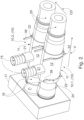
- Figure 2 shows one embodiment of dilution elements 10 for headbox 30 of a fibre web machine.
- the figure shows two dilution elements 10 as if they were installed in parallel in headbox 30 without the other surrounding structures in headbox 30.
- Dilution element 10 according to the invention is installable in a replaceable manner in connection with headbox 30 of a fibre web machine, the more detailed structure of headbox 30 to be presented on a level of principle as an example in Figure 7 and described further below in the description.
- the fibre web machine can be a paper or board machine, pulp-drying machine or tissue machine, among other things.
- Headbox 30 is used for spreading and supplying stock flow 44 to the forming section of a fibre web machine in a manner known in itself.
- Dilution element 10 is used for adjusting the consistency of stock flow 38 coming from manifold 26.1, 26.2 before supplying the stock flow forward in flow direction F in headbox 30.
- the purpose, principle of operation and importance of dilution element 10 in headbox 30 of a fibre web machine are obvious for a person having ordinary skill in the art, which is why they are not described in more detail here.
- Dilution element 10 includes mixing space 14 adapted to be formed inside it and flow openings 15, 19 and 20 for inlet and outlet.
- Mixing space 14, of which there is now one in dilution element 10, is adapted to be formed inside dilution element 10.
- dilution water 37 is mixed in mixing space 14 in the set manner into stock flow 38 supplied into mixing space 14, after which diluted stock flow 44 exits mixing space 14 forward in flow direction F.
- Stock flow 44 diluted in mixing space 14 is supplied further in flow direction F of headbox 30 towards the next section of headbox 30 and hence also towards the forming section.
- Openings 15, 19, 20 included in dilution element 10 are adapted to converge in mixing space 14.
- Dilution water 37 is adapted to be supplied through first opening 15 into mixing space 14.
- Stock flow 38 is adapted to be supplied through second opening 19 from manifold 26.1, 26.2 into mixing space 14. This takes place by means of inlet pipe 16 adaptable in opening 19.
- Inlet pipe 16 is adapted to be sealed against inner surface 25 of second opening 19.
- Stock flow 38 diluted with dilution water 37 in mixing space 14 is adapted to be supplied as diluted stock flow 44 through third opening 20 from mixing space 14 forward in flow direction F.
- outlet pipe 29 adaptable in opening 20.
- Outlet pipe 29 is adapted to be sealed against inner surface 27 of third opening 20.
- openings 15, 19, 20 is adapted in dilution element 10 so that second and third openings 19, 20 are adapted in dilution element 10 on the opposite sides of headbox 30 in flow direction F of headbox 30.
- Opening 15 for dilution water and its flow direction are mainly at a right angle or at a sharp angle with respect to flow direction F of stock flows 38, 44.
- Dilution element 10 is adapted to be formed by pipe sleeve 11 over its section between second and third openings 19, 20.
- dilution element 10 is a solid structural piece with a single part and a single material and a pipe-like cross section in flow direction F of headbox 30, adapted into the shape of a pipe.
- Mixing space 14 is also adapted to be formed inside pipe sleeve 11, between second and third openings 19, 20.
- the outer surface of shell 12 of pipe sleeve 11 is a solid of revolution, such as a cylinder.
- the wall thickness of shell 12 is relatively small in relation to, for example, the diameter of pipe channel 13 formed inside pipe sleeve 11, or in general in relation to outer diameter D of pipe sleeve 11.
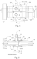
- Figure 4 shows dilution elements 10.1, 10.2 of Figure 2 from above
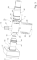
- Figure 3 shows one dilution element 10 of Figures 2 and 4 as an exploded figure
- Figure 5 shows one dilution element 10 shown in Figures 2-4 in cross section in machine direction MD.
- Figure 6 shows dilution element 10 that is shown in cross section in Figure 5 separate from inlet and outlet pipes 16, 29 that can be connected to it.
- inlet pipe 16 and outlet pipe 29 are adapted to be fastened to dilution element 10 by means of spring pin fastening 22.
- Spring pin fastening 22 is adapted to influence inlet pipe 16 and outlet pipe 29 through shell 12 of pipe sleeve 11.
- Pipe sleeve 11 includes, as shown in Figure 3 , notches 24 for spring pin fastening 22. During fastening, spring pins 39 fit in notches 24.
- inlet pipe 16 and outlet pipe 29 include grooves 43 adapted on their outer surface 41, 42 as shown in, for example, Figure 6 , for spring pin fastening 22 of pipes 16, 20 to dilution element 10.
- Sealing 23.1, 23.2 is adaptable between inner surface 25 of inlet side opening 19 and inlet pipe 16 of dilution element 10 as well as between the outlet side of dilution element 10, in other words between inner surface 27 of third opening 20 and outlet pipe 29, as shown in Figures 5 and 6 .
- inlet and outlet pipes 16, 29 have sealing grooves 45 shown in Figure 6 , into which grooves the seal (not illustrated) settles. While the seal is in groove 45, the seal presses against inner surfaces 25, 27 of second and third openings 19, 20.
- Spring pin fastening 22 is adapted on the opposite side of sealing 23.1, 23.2 with respect to the mixing chamber.
- Outlet end 16' of inlet pipe 16 of dilution element 10 is located inside pipe sleeve 11.
- Inlet pipe 16 extends into pipe sleeve 11 in the direction of travel of the stock flow, at least to opening 15 of the pipe connection of pipe sleeve 11.
- Dilution water 37 supplied through pipe connection 21 of pipe sleeve 11 is advantageously directed to the outer surface of inlet pipe 16, from where it is directed into the stock flow through a ring-shaped opening, which is formed between the ends of inlet pipe 16 and outlet pipe 29.
- Inlet end 29' of outlet pipe 29 of dilution element 10 is located inside pipe sleeve 11, advantageously in the direction of travel of the stock flow after opening 15 of the pipe connection of pipe sleeve 11. The mixed stock flow and dilution water are supplied through outlet pipe 29.
- the inner diameter of pipe channel 13 ( Figure 6 ) adapted to be formed between second opening 19 and third opening 20 of pipe sleeve 11 is adapted to be larger on the side of third opening 20 than on the side of second opening 19.
- the cross-sectional area of the chamber space formed at the end of outlet pipe 29 bigger than the cross section of inlet pipe 16. The result of this is that a ring-shaped gap, through which dilution water 37 is supplied into mixing space 14 with the principle of ring dilution, is formed between the ends of inlet pipe 16 and outlet pipe 29.
- dilution water 37 is brought together with stock flow 38 that is supplied from the manifold into mixing space 14 and discharged into it from inlet pipe 16 in a manner that surrounds stock flow 38.
- Figure 5 shows well this size difference between the ends of pipes 16, 29.
- Figure 5 also shows well the small gap remaining between the outlet end of inlet pipe 16 adapted in mixing space 14 and the inlet end of outlet pipe 29, from which gap dilution water 37 supplied into mixing space 14 through connection 21 can mix with main stock flow 38 of headbox 30 coming along inlet pipe 16.
- mixing space 14 is adapted to be formed in pipe sleeve 11, when inlet pipe 16 and outlet pipe 29 are adapted in openings 19, 20 of pipe sleeve 11.
- First opening 15 is adapted in shell 12 of pipe sleeve 11 to join adapted pipe connection 21.
- Pipe connection 21 is arranged to join pipe sleeve 11, for example, perpendicularly or at a sharp angle (in the direction of travel of stock flows 38, 44).
- dilution element 10 is adaptable to be supported to headbox 30 structures 17, 18 indirectly by means of inlet pipe 16 and outlet pipe 29.
- pipe sleeve 11 is not in direct structural contact by, for example, its shell 12 to headbox 30 structures 17, 18.
- pipe sleeve 11 is arrangeable so that it is not directly supported to headbox 30 structures 17, 18.
- dilution elements 10 can be fastened to headbox 30 manifold 26.1, 26.2 via inlet pipe 16, for example, via distribution plate 17. The flow that turns from manifold 26.1, 26.2 is supplied via inlet pipe 16 into mixing space 14 adapted to be formed in pipe sleeve 11.
- outer diameter D of pipe sleeve 11 adapted to form dilution element 10 is adapted as shown in Figures 2 and 4 so that adjacent dilution elements 10.1, 10.2 arranged in connection with headbox 30 are adapted to be supported to each other in cross direction CD of headbox 30.
- dilution element 10.1 is adapted to be supported at its installation site by its sides to adjacent elements 10.2 in order to reduce the pressure load, which is usually significant, considering the operating conditions of headbox 30.
- dilution elements 10 are side by side and in contact with each other. Dilution elements 10 are in contact with each other linearly only by their sides, by their shell 12.
- dilution element 10 in other words pipe sleeve 11, can be made from, for example, plastic material, by using the die casting technique, for example.
- dilution element 10 can also be manufactured as a 3D printout, for example.
- headbox 30 In addition to dilution element 10, the invention also relates to headbox 30, one example of which is presented in Figure 7 .
- the basic components of headbox 30 include manifold 26, 26.1, 26.2, dilution elements 10 and turbulence generator 33.
- the headbox shown in the application example presented is a double layer headbox 31.
- Mixing space 14 is adapted to be formed in each dilution element 10, into which mixing space 14 stock flow 38 is adapted to be supplied from manifold 26.1, 26.2 via inlet pipe 16, and into which mixing space 14 dilution water 37 is adapted to be supplied in order to dilute stock flow 38 in mixing space 14.
- stock flow 44 diluted with dilution water 37 is adapted to be supplied from dilution elements 10 forward in flow direction F of headbox 30 via outlet pipe 29.
- Outlet pipe 29 can connect to a distribution pipe included in piping 32, which distribution pipe supplies diluted stock flow 44 further to turbulence generator 33, lip channel 34, slice 35 and further to the forming section wire 36 for web W formation.
- Dilution element 10 is a dilution element according to the invention, where its section between second and third openings 19, 20 is adapted to be formed by pipe sleeve 11, inside which mixing space 14 is adapted to be formed. Moreover, first opening 15, which supplies dilution water 37 into pipe sleeve 11, is adapted in shell 12 of pipe sleeve 11.
- manifold 26.1, 26.2 is fitted with distribution plate 17 provided with openings 40, the height H of which distribution plate 17 is adapted to correspond to dilution element 10.
- the height H of distribution plate 17 remains moderate and requires less material.
- the solution according to the invention can also be utilised in headboxes with more than one tube row in the manifold tube bank.
- headboxes with two manifold tube banks one on top of the other it is possible to use a pipe sleeve that extends to both tube banks in the height direction.
- dilution water is supplied into tubes in both superimposed tube banks through the same dilution connection.
Abstract
The invention relates to a dilution element (10) for a headbox (30) of a fibre web machine, which dilution element is adaptable in connection with a headbox and which includes at least one mixing space (14) adapted to be formed inside the dilution element, openings (15, 19, 20) adapted in the dilution element, adapted to merge in the mixing space, where dilution water (37) is adapted to be supplied through the first opening (15) into the mixing space, a stock flow (38) is adapted to be supplied through the second opening (19) from a manifold (26, 26.1, 26.2) into the mixing space by means of an inlet pipe (16) adaptable in the opening, a stock flow (44) diluted with dilution water in the mixing space is adapted to be supplied through the third opening (20) from the mixing space forward in the flow direction (F) by means of an outlet pipe (29) adaptable in the opening, which outlet pipe is adapted to be sealed against the inner surface (27) of the third opening, and over its section between the second and third openings, the dilution element is adapted to be formed by a pipe sleeve (11), inside which said mixing space is adapted to be formed, and the first opening is adapted in the shell (12) of the pipe sleeve. The inlet pipe (16) of the dilution element extends into the pipe sleeve in the direction of travel of the stock flow, to at least the first opening in the pipe sleeve, and the inlet pipe is adapted to be sealed against the inner surface of the pipe sleeve. The invention also relates to a headbox of a fibre web machine.
Description
- The invention relates to a dilution element for a headbox of a fibre web machine, which is adaptable in connection with a headbox and which includes:
- at least one mixing space adapted to be formed inside the dilution element,
- openings adapted in the dilution element, adapted to merge in the mixing space, through which openings:
- dilution water is adapted to be supplied through a first opening into the mixing space,
- a stock flow is adapted to be supplied through a second opening from a manifold into the mixing space by means of an inlet pipe adaptable in the opening,
- a stock flow diluted with dilution water in the mixing space is adapted to be supplied through a third opening from the mixing space forward in the flow direction by means of an outlet pipe adaptable in the opening, which outlet pipe is adapted to be sealed against the inner surface of the third opening,
- over its section between the second and third openings, the dilution element is adapted to be formed by a pipe sleeve, inside which said mixing space is adapted to be formed, and the first opening is adapted in the shell of the pipe sleeve.
- The invention also relates to a headbox of a fibre web machine.
- Being a massive structural component, the applicant's dilution element for headboxes is expensive to manufacture. Moreover, due to the massiveness of the structural component, it is also not possible to sensibly change its dimensions afterwards. The structural component is a solid sheet piece with the same width as the entire machine, and holes have been machined in the piece over the entire width of the machine for the stock flow and dilution water supply taking place through it and for their mixing inside the structural component.
-
Figure 1 shows one example of a prior art solution, with the headbox in cross section in the cross direction of the machine. In the Figure,stock flow 38 is supplied frommanifold 26 through distribution plate 17',inlet pipe 16 adapted in it, dilution element 10',outlet pipe 29 anddistribution pipe 32 forward to the turbulence generator (through an intermediate chamber) and from there further to the wire section (not shown). Dilution water supply has its own connection with opening 15 throughpipe connection 21 adapted to dilution element 10'. -
Dilution element 10 is formed by structural piece 11.1 and its cover 11.2 adapted and joined to each other one after the other in machine direction MD. In this case, mixingspaces 14 are formed inside dilution element 10', and dilution water supplied intomixing spaces 14 is mixed with the stock flow supplied intomixing spaces 14 frommanifold 26. In this way, a single dilution element 10' contains severalseparate mixing spaces 14 side by side in the cross direction of the machine. As can be seen inFigure 1 , structural piece 11.1 and also its cover 11.2 are a sheet piece with a solid cross section and a height which is considerably high with respect to the height of the through-flow channel and mixingspace 14, and its manufacturing and also supporting to headbox structures 17' also involve welding. When implemented in this way, the structures become considerably expensive. - The objective of the present invention is to accomplish a dilution element for the headbox of a fibre web machine, where the dilution element has a light and simple structure and is also easier to build. The characteristic features of the dilution element according to the invention will be more fully understood from claim 1. Another objective of the invention is to accomplish a fibre web machine headbox, which is easier to manufacture and has a lighter structure. The characteristic features of the headbox according to the invention will be more fully understood from
claim 10. - The inlet pipe of the dilution water element extends into the pipe sleeve in the direction of travel of the stock flow, to at least the first opening in the pipe sleeve, and the inlet pipe is adapted to be sealed against the inner surface of the pipe sleeve.
- The design flow of the dilution element is easily modifiable with the invention, because each dilution element in the headbox is a separate structural item and hence easily replaceable in the headbox. Moreover, the dilution element and its manufacture tie less capital. The manufacture of the dilution element is also simplified, when, instead of a massive machined solid plate piece, the dilution element can be implemented as a simple and light pipe sleeve.
- The manufacture of the dilution element according to the invention does not require large-scale machine tools. The further specification of the details of the element during its design stage enables the implementation of an as simple structure as possible, both in terms of materials and structure. The other additional advantages to be achieved with the invention are disclosed in the description of the invention, and the characteristics are disclosed in the claims.
- The invention, which is not restricted to the embodiments presented below, is described in more detail by making reference to the enclosed drawings, in which:
- Figure 1
- shows one example of a prior art dilution element in the headbox in the cross section in its machine direction,
- Figure 2
- shows two dilution elements according to the invention when installed into place,
- Figure 3
- shows an exploded figure of one dilution element shown in
Figure 2 , - Figure 4
- shows two dilution elements viewed from above,
- Figure 5
- shows one dilution element shown in
Figure 4 in cross section in the machine direction, - Figure 6
- shows the dilution element that is shown in cross section in
Figure 5 separate from the inlet and outlet pipes that can be connected to it, and - Figure 7
- shows one example of a headbox seen from the side, where the dilution element according to the invention can be applied, and its placement therein.
-
Figure 2 shows one embodiment ofdilution elements 10 forheadbox 30 of a fibre web machine. The figure shows twodilution elements 10 as if they were installed in parallel inheadbox 30 without the other surrounding structures inheadbox 30.Dilution element 10 according to the invention is installable in a replaceable manner in connection withheadbox 30 of a fibre web machine, the more detailed structure ofheadbox 30 to be presented on a level of principle as an example inFigure 7 and described further below in the description. The fibre web machine can be a paper or board machine, pulp-drying machine or tissue machine, among other things.Headbox 30 is used for spreading and supplyingstock flow 44 to the forming section of a fibre web machine in a manner known in itself. -
Dilution element 10 is used for adjusting the consistency ofstock flow 38 coming from manifold 26.1, 26.2 before supplying the stock flow forward in flow direction F inheadbox 30. The purpose, principle of operation and importance ofdilution element 10 inheadbox 30 of a fibre web machine are obvious for a person having ordinary skill in the art, which is why they are not described in more detail here. -
Dilution element 10 includes mixingspace 14 adapted to be formed inside it and flowopenings space 14, of which there is now one indilution element 10, is adapted to be formed insidedilution element 10. As shown inFigure 5 ,dilution water 37 is mixed in mixingspace 14 in the set manner intostock flow 38 supplied into mixingspace 14, after which dilutedstock flow 44exits mixing space 14 forward in flow direction F. Stock flow 44 diluted in mixingspace 14 is supplied further in flow direction F ofheadbox 30 towards the next section ofheadbox 30 and hence also towards the forming section. -
Openings dilution element 10 are adapted to converge in mixingspace 14.Dilution water 37 is adapted to be supplied throughfirst opening 15 into mixingspace 14.Stock flow 38 is adapted to be supplied throughsecond opening 19 from manifold 26.1, 26.2 into mixingspace 14. This takes place by means ofinlet pipe 16 adaptable inopening 19.Inlet pipe 16 is adapted to be sealed againstinner surface 25 ofsecond opening 19.Stock flow 38 diluted withdilution water 37 in mixingspace 14 is adapted to be supplied as dilutedstock flow 44 throughthird opening 20 from mixingspace 14 forward in flow direction F. This takes place by means ofoutlet pipe 29 adaptable inopening 20.Outlet pipe 29 is adapted to be sealed againstinner surface 27 ofthird opening 20. - The arrangement of
openings dilution element 10 so that second andthird openings dilution element 10 on the opposite sides ofheadbox 30 in flow direction F ofheadbox 30. Opening 15 for dilution water and its flow direction, in turn, are mainly at a right angle or at a sharp angle with respect to flow direction F ofstock flows -
Dilution element 10 is adapted to be formed bypipe sleeve 11 over its section between second andthird openings case dilution element 10 is a solid structural piece with a single part and a single material and a pipe-like cross section in flow direction F ofheadbox 30, adapted into the shape of a pipe. Mixingspace 14 is also adapted to be formed insidepipe sleeve 11, between second andthird openings shell 12 ofpipe sleeve 11 is a solid of revolution, such as a cylinder. The wall thickness ofshell 12 is relatively small in relation to, for example, the diameter ofpipe channel 13 formed insidepipe sleeve 11, or in general in relation to outer diameter D ofpipe sleeve 11. -
Figure 4 shows dilution elements 10.1, 10.2 ofFigure 2 from above,Figure 3 shows onedilution element 10 ofFigures 2 and4 as an exploded figure, andFigure 5 shows onedilution element 10 shown inFigures 2-4 in cross section in machine direction MD.Figure 6 , in turn, showsdilution element 10 that is shown in cross section inFigure 5 separate from inlet andoutlet pipes inlet pipe 16 andoutlet pipe 29 are adapted to be fastened todilution element 10 by means ofspring pin fastening 22. Spring pin fastening 22 is adapted to influenceinlet pipe 16 andoutlet pipe 29 throughshell 12 ofpipe sleeve 11.Pipe sleeve 11 includes, as shown inFigure 3 ,notches 24 forspring pin fastening 22. During fastening, spring pins 39 fit innotches 24. In this case, according to one embodiment,inlet pipe 16 andoutlet pipe 29 includegrooves 43 adapted on theirouter surface Figure 6 , for spring pin fastening 22 ofpipes dilution element 10. - Sealing 23.1, 23.2 is adaptable between
inner surface 25 ofinlet side opening 19 andinlet pipe 16 ofdilution element 10 as well as between the outlet side ofdilution element 10, in other words betweeninner surface 27 ofthird opening 20 andoutlet pipe 29, as shown inFigures 5 and6 . For sealing 23.1, 23.2, inlet andoutlet pipes grooves 45 shown inFigure 6 , into which grooves the seal (not illustrated) settles. While the seal is ingroove 45, the seal presses againstinner surfaces third openings - Outlet end 16' of
inlet pipe 16 ofdilution element 10 is located insidepipe sleeve 11.Inlet pipe 16 extends intopipe sleeve 11 in the direction of travel of the stock flow, at least to opening 15 of the pipe connection ofpipe sleeve 11.Dilution water 37 supplied throughpipe connection 21 ofpipe sleeve 11 is advantageously directed to the outer surface ofinlet pipe 16, from where it is directed into the stock flow through a ring-shaped opening, which is formed between the ends ofinlet pipe 16 andoutlet pipe 29. Inlet end 29' ofoutlet pipe 29 ofdilution element 10 is located insidepipe sleeve 11, advantageously in the direction of travel of the stock flow after opening 15 of the pipe connection ofpipe sleeve 11. The mixed stock flow and dilution water are supplied throughoutlet pipe 29. - According to one embodiment, the inner diameter of pipe channel 13 (
Figure 6 ) adapted to be formed betweensecond opening 19 andthird opening 20 ofpipe sleeve 11 is adapted to be larger on the side ofthird opening 20 than on the side ofsecond opening 19. In this way, it is possible to make the cross-sectional area of the chamber space formed at the end ofoutlet pipe 29 bigger than the cross section ofinlet pipe 16. The result of this is that a ring-shaped gap, through whichdilution water 37 is supplied into mixingspace 14 with the principle of ring dilution, is formed between the ends ofinlet pipe 16 andoutlet pipe 29. In other words,dilution water 37 is brought together withstock flow 38 that is supplied from the manifold into mixingspace 14 and discharged into it frominlet pipe 16 in a manner that surroundsstock flow 38.Figure 5 shows well this size difference between the ends ofpipes -
Figure 5 also shows well the small gap remaining between the outlet end ofinlet pipe 16 adapted in mixingspace 14 and the inlet end ofoutlet pipe 29, from whichgap dilution water 37 supplied into mixingspace 14 throughconnection 21 can mix withmain stock flow 38 ofheadbox 30 coming alonginlet pipe 16. In this way, mixingspace 14 is adapted to be formed inpipe sleeve 11, wheninlet pipe 16 andoutlet pipe 29 are adapted inopenings pipe sleeve 11. - First opening 15, through which dilution is brought into
pipe sleeve 11 and further into its mixingspace 14, is adapted inshell 12 ofpipe sleeve 11. First opening 15 is adapted inshell 12 ofpipe sleeve 11 to join adaptedpipe connection 21.Pipe connection 21 is arranged to joinpipe sleeve 11, for example, perpendicularly or at a sharp angle (in the direction of travel of stock flows 38, 44). - In accordance with
Figures 2 and4 ,dilution element 10, or nowpipe sleeve 11, is adaptable to be supported to headbox 30structures 17, 18 indirectly by means ofinlet pipe 16 andoutlet pipe 29. In this way,pipe sleeve 11 is not in direct structural contact by, for example, itsshell 12 to headbox 30structures 17, 18. In other words,pipe sleeve 11 is arrangeable so that it is not directly supported to headbox 30structures 17, 18. On their inlet side,dilution elements 10 can be fastened to headbox 30 manifold 26.1, 26.2 viainlet pipe 16, for example, viadistribution plate 17. The flow that turns from manifold 26.1, 26.2 is supplied viainlet pipe 16 into mixingspace 14 adapted to be formed inpipe sleeve 11. - According to one embodiment, outer diameter D of
pipe sleeve 11 adapted to formdilution element 10 is adapted as shown inFigures 2 and4 so that adjacent dilution elements 10.1, 10.2 arranged in connection withheadbox 30 are adapted to be supported to each other in cross direction CD ofheadbox 30. In this way, dilution element 10.1 is adapted to be supported at its installation site by its sides to adjacent elements 10.2 in order to reduce the pressure load, which is usually significant, considering the operating conditions ofheadbox 30. This can be seen well inFigure 4 , wheredilution elements 10 are side by side and in contact with each other.Dilution elements 10 are in contact with each other linearly only by their sides, by theirshell 12. - According to one embodiment,
dilution element 10, in otherwords pipe sleeve 11, can be made from, for example, plastic material, by using the die casting technique, for example. On the other hand,dilution element 10 can also be manufactured as a 3D printout, for example. - In addition to
dilution element 10, the invention also relates to headbox 30, one example of which is presented inFigure 7 . The basic components ofheadbox 30 includemanifold 26, 26.1, 26.2,dilution elements 10 andturbulence generator 33. The headbox shown in the application example presented is adouble layer headbox 31. - Mixing
space 14 is adapted to be formed in eachdilution element 10, into which mixingspace 14stock flow 38 is adapted to be supplied from manifold 26.1, 26.2 viainlet pipe 16, and into which mixingspace 14dilution water 37 is adapted to be supplied in order to dilutestock flow 38 in mixingspace 14. Moreover,stock flow 44 diluted withdilution water 37 is adapted to be supplied fromdilution elements 10 forward in flow direction F ofheadbox 30 viaoutlet pipe 29.Outlet pipe 29 can connect to a distribution pipe included in piping 32, which distribution pipe supplies dilutedstock flow 44 further toturbulence generator 33,lip channel 34,slice 35 and further to the formingsection wire 36 for web W formation. -
Dilution element 10 is a dilution element according to the invention, where its section between second andthird openings pipe sleeve 11, inside which mixingspace 14 is adapted to be formed. Moreover,first opening 15, which suppliesdilution water 37 intopipe sleeve 11, is adapted inshell 12 ofpipe sleeve 11. - According to one embodiment, in accordance with
Figures 2-6 , manifold 26.1, 26.2 is fitted withdistribution plate 17 provided withopenings 40, the height H of whichdistribution plate 17 is adapted to correspond todilution element 10. In this case, the height H ofdistribution plate 17 remains moderate and requires less material. - The solution according to the invention can also be utilised in headboxes with more than one tube row in the manifold tube bank. In this case, for example, in headboxes with two manifold tube banks one on top of the other it is possible to use a pipe sleeve that extends to both tube banks in the height direction. In this case, dilution water is supplied into tubes in both superimposed tube banks through the same dilution connection.
- It is to be understood that the above description and the related figures are only intended to illustrate the present invention. The invention is hence not only restricted to the above-presented embodiments, but several different variations and adaptations of the invention will also be obvious to a person having ordinary skill in the art, which variations and adaptations are possible within the inventive idea defined by the enclosed claims.
Claims (12)
- A dilution element for a headbox of a fibre web machine, which dilution element is adaptable in connection with a headbox (30) and which includes:- at least one mixing space (14) adapted to be formed inside the dilution element (10),- openings (15, 19, 20) adapted in the dilution element (10), adapted to merge in the mixing space (14), where:- dilution water (37) is adapted to be supplied through the first opening (15) into the mixing space (14),- a stock flow (38) is adapted to be supplied through the second opening (19) from a manifold (26, 26.1, 26.2) into the mixing space (14) by means of an inlet pipe (16) adaptable in the opening (19),- a stock flow (44) diluted with dilution water (37) in the mixing space (14) is adapted to be supplied through the third opening (20) from the mixing space (14) forward in the flow direction (F) by means of an outlet pipe (29) adaptable in the opening (20), which outlet pipe (29) is adapted to be sealed against the inner surface (27) of the third opening (20),- over its section between the second and third openings (19, 20), the dilution element (10) is adapted to be formed by a pipe sleeve (11), inside which said mixing space (14) is adapted to be formed, and the first opening (15) is adapted in the shell (12) of the pipe sleeve (11),
characterised in that- the inlet pipe (16) extends into the pipe sleeve (11) in the direction of travel of the stock flow, to at least the first opening (15) in the pipe sleeve (11), and the inlet pipe is adapted to be sealed against the inner surface (25) of the pipe sleeve (11). - A dilution element according to claim 1, characterised in that the inlet end (29') of the outlet pipe (29) of the dilution element (10) is located inside the pipe sleeve (11), advantageously in the direction of travel of the stock flow after the opening (15) of the pipe connection of the pipe sleeve (11).
- A dilution element according to claim 1 or 2, characterised in that the dilution element (10) is adaptable to be supported to the headbox (30) structures (17, 18) indirectly by means of the inlet pipe (16) and the outlet pipe (29).
- A dilution element according to claim 1 or 2, characterised in that the first opening (15) is adapted to the pipe connection (21), which is arranged to connect to the pipe sleeve (11) perpendicularly or at a sharp angle.
- A dilution element according to any one of the claims 1-4, characterised in that the inlet pipe (16) and the outlet pipe (29) are adapted to be fastened to the dilution element (10) by means of a spring pin fastening (22), which is adapted to influence them through the pipe sleeve (11).
- A dilution element according to any one of the claims 1-5, characterised in that the outer diameter (D) of the pipe sleeve (11) is adapted so that adjacent dilution elements (10.1, 10.2) arranged in connection with the headbox (30) are adapted to be supported to each other in the cross direction (CD) of the headbox (30).
- A dilution element according to claim 5 or 6, characterised in that a sealing (23.1, 23.2) is adaptable between the inlet pipe (16) and outlet pipe (29) and the inner surface (25, 27) of the dilution element (10), and the spring pin fastening (22) is adapted on the opposite side of the sealing (23.1, 23.2) with respect to the mixing space (14).
- A dilution element according to any one of the claims 5-7, characterised in that the pipe sleeve (11) includes notches (24) for the spring pin fastening (22).
- A dilution element according to any one of the claims 1-8, characterised in that the inner diameter of the pipe channel (13) adapted to be formed between the second opening (19) and the third opening (20) of the pipe sleeve (11) is adapted to be larger on the side of the third opening (20) than on the side of the second opening (19).
- A fibre web machine headbox, which includes:- a manifold (26, 26.1, 26.2),- dilution elements (10) with mixing spaces (14) adapted to be formed therein, which mixing spaces (14) are adapted to be supplied with a stock flow (38) from a manifold (26, 26.1, 26.2) through an inlet pipe (16) and with dilution water (37) in order to dilute the stock flow (38) and from which mixing spaces (14) a stock flow (44) diluted with dilution water (37) is adapted to be supplied forward in the flow direction (F) of the headbox (30) through the outlet pipe (29),- a turbulence generator (33) and a pipeline (32) leading to it from the dilution elements (10),characterised in that the dilution element (10) is a dilution element according to any one of the claims 1-9.
- A headbox according to claim 10, characterised in that the manifold (26) is fitted with a distribution plate (17) provided with openings (40), the height (H) of which distribution plate (17) is adapted to correspond to the dilution element (10).
- A headbox according to claim 10 or 11, characterised in that the inlet pipe (16) and the outlet pipe (29) include grooves (43) adapted on their outer surface (41, 42) for the spring pin fastening (22) of the pipes (16, 20) to the dilution element (10).
Applications Claiming Priority (1)
| Application Number | Priority Date | Filing Date | Title |
|---|---|---|---|
| FI20236054A FI131824B1 (en) | 2023-09-22 | 2023-09-22 | Dillution element for a head box of a fibre web machine, and head box of a fibre web machine |
Publications (1)
| Publication Number | Publication Date |
|---|---|
| EP4528025A1 true EP4528025A1 (en) | 2025-03-26 |
Family
ID=92542723
Family Applications (1)
| Application Number | Title | Priority Date | Filing Date |
|---|---|---|---|
| EP24196374.3A Pending EP4528025A1 (en) | 2023-09-22 | 2024-08-26 | Dilution element for headbox of fibre web machine, and headbox of fibre web machine |
Country Status (3)
| Country | Link |
|---|---|
| EP (1) | EP4528025A1 (en) |
| CN (1) | CN119686149A (en) |
| FI (1) | FI131824B1 (en) |
Citations (5)
| Publication number | Priority date | Publication date | Assignee | Title |
|---|---|---|---|---|
| US20040140576A1 (en) * | 2001-05-01 | 2004-07-22 | La Crosse Gaylen R. | Treatment of water with contaminants |
| WO2011039190A1 (en) * | 2009-09-29 | 2011-04-07 | Siemens Aktiengesellschaft | Device, flotation machine equipped therewith, and methods for the operation thereof |
| WO2011095251A1 (en) * | 2010-02-03 | 2011-08-11 | Voith Patent Gmbh | Valve for regulating a fluid flow |
| WO2011134682A1 (en) * | 2010-04-30 | 2011-11-03 | Voith Patent Gmbh | Valve for regulating a fluid flow |
| WO2021243121A1 (en) * | 2020-05-29 | 2021-12-02 | Kimberly-Clark Worldwide, Inc. | Apparatus for forming a substrate |
Family Cites Families (2)
| Publication number | Priority date | Publication date | Assignee | Title |
|---|---|---|---|---|
| SE506322C2 (en) * | 1996-03-08 | 1997-12-01 | Valmet Karlstad Ab | Device for feeding stock to an inlet box in a paper machine |
| FI110701B (en) * | 1996-03-08 | 2003-03-14 | Metso Paper Inc | Plant for combining a dilution stream with the pulp stream discharged from the distribution boom in a paper machine / cardboard machine |
-
2023
- 2023-09-22 FI FI20236054A patent/FI131824B1/en active
-
2024
- 2024-08-26 EP EP24196374.3A patent/EP4528025A1/en active Pending
- 2024-09-13 CN CN202411284433.4A patent/CN119686149A/en active Pending
Patent Citations (5)
| Publication number | Priority date | Publication date | Assignee | Title |
|---|---|---|---|---|
| US20040140576A1 (en) * | 2001-05-01 | 2004-07-22 | La Crosse Gaylen R. | Treatment of water with contaminants |
| WO2011039190A1 (en) * | 2009-09-29 | 2011-04-07 | Siemens Aktiengesellschaft | Device, flotation machine equipped therewith, and methods for the operation thereof |
| WO2011095251A1 (en) * | 2010-02-03 | 2011-08-11 | Voith Patent Gmbh | Valve for regulating a fluid flow |
| WO2011134682A1 (en) * | 2010-04-30 | 2011-11-03 | Voith Patent Gmbh | Valve for regulating a fluid flow |
| WO2021243121A1 (en) * | 2020-05-29 | 2021-12-02 | Kimberly-Clark Worldwide, Inc. | Apparatus for forming a substrate |
Also Published As
| Publication number | Publication date |
|---|---|
| FI20236054A1 (en) | 2025-03-23 |
| FI131824B1 (en) | 2025-12-17 |
| CN119686149A (en) | 2025-03-25 |
Similar Documents
| Publication | Publication Date | Title |
|---|---|---|
| US8221590B2 (en) | Headbox for a machine for producing a fibrous web | |
| US8303774B2 (en) | Headbox for a machine for producing a fibrous web | |
| US20120168105A1 (en) | Headbox for a machine for producing a fibrous web | |
| US8236137B2 (en) | Headbox for a machine for producing a fibrous web | |
| CN101622399B (en) | Structural element for a functional member of a headbox in a web-manufacturing machine, functional member and headbox made thereof, and associated methods | |
| GB1569430A (en) | Headboxes for paper-making machines | |
| FI115646B (en) | Multi-layer inlet box for paper machine / cardboard machine | |
| EP2655734B1 (en) | Turbulence generator of a headbox of a fibre web machine | |
| CA2160754C (en) | Process for the production of a breast box for a paper or cartonmaking machine as well as an intermediate portion for carrying out the process | |
| EP1102885B1 (en) | Equipment and method in a paper or board machine for mixing of fresh stock and of water for dilution of fresh stock | |
| US3878039A (en) | Paper machine headbox having convergent throat portion | |
| CN115218172B (en) | Spiral-lock type flow channel plugging device and method for steam generator | |
| FI3491186T3 (en) | Flow module and method for producing a flow module for a flowbox of a papermaking machine | |
| DE10234559A1 (en) | Papermaking machine for low-volume paper or carton has vortex generator block made of a single integral plastic unit with jets discharging to sieve belt | |
| US5000227A (en) | Pressurized fluid carrier conduit connection | |
| CN119686149A (en) | Dilution element for a headbox of a web machine and headbox of a fiber web machine | |
| US5800678A (en) | Method and device for regulating a flow of dilution liquid in connection with a headbox of a paper/board machine | |
| US20070056708A1 (en) | Apparatus in connection with a headbox of a paper machine or equivalent | |
| FI125950B (en) | Multilayer Outlet Box | |
| DE102007026386B4 (en) | Roll body with profile channels for a tempering fluid | |
| DE102007029046A1 (en) | Roller for transferring heat to or from fibrous sheet, e.g. during paper-making, has heat transfer medium flow space between inner and thin outer parts of external casing | |
| US4895624A (en) | Turbulence generator made of plastic with ceramic coated flow ducts in the head box of a paper machine | |
| FI110528B (en) | Plant in connection with an inlet box in a paper machine / cardboard machine | |
| US6197161B1 (en) | Profile bar assembly for a headbox in a paper-making machine | |
| US20030159790A1 (en) | Process and headbox of a machine for producing a fibrous material web |
Legal Events
| Date | Code | Title | Description |
|---|---|---|---|
| PUAI | Public reference made under article 153(3) epc to a published international application that has entered the european phase |
Free format text: ORIGINAL CODE: 0009012 |
|
| STAA | Information on the status of an ep patent application or granted ep patent |
Free format text: STATUS: THE APPLICATION HAS BEEN PUBLISHED |
|
| AK | Designated contracting states |
Kind code of ref document: A1 Designated state(s): AL AT BE BG CH CY CZ DE DK EE ES FI FR GB GR HR HU IE IS IT LI LT LU LV MC ME MK MT NL NO PL PT RO RS SE SI SK SM TR |
|
| STAA | Information on the status of an ep patent application or granted ep patent |
Free format text: STATUS: REQUEST FOR EXAMINATION WAS MADE |
|
| 17P | Request for examination filed |
Effective date: 20250703 |