EP4528013A1 - Laundry treating apparatus - Google Patents
Laundry treating apparatus Download PDFInfo
- Publication number
- EP4528013A1 EP4528013A1 EP23824242.4A EP23824242A EP4528013A1 EP 4528013 A1 EP4528013 A1 EP 4528013A1 EP 23824242 A EP23824242 A EP 23824242A EP 4528013 A1 EP4528013 A1 EP 4528013A1
- Authority
- EP
- European Patent Office
- Prior art keywords
- panel
- top panel
- cabinet
- coupling
- treating apparatus
- Prior art date
- Legal status (The legal status is an assumption and is not a legal conclusion. Google has not performed a legal analysis and makes no representation as to the accuracy of the status listed.)
- Pending
Links
Images














Classifications
-
- D—TEXTILES; PAPER
- D06—TREATMENT OF TEXTILES OR THE LIKE; LAUNDERING; FLEXIBLE MATERIALS NOT OTHERWISE PROVIDED FOR
- D06F—LAUNDERING, DRYING, IRONING, PRESSING OR FOLDING TEXTILE ARTICLES
- D06F39/00—Details of washing machines not specific to a single type of machines covered by groups D06F9/00 - D06F27/00
- D06F39/001—Arrangements for transporting, moving, or setting washing machines; Protective arrangements for use during transport
-
- D—TEXTILES; PAPER
- D06—TREATMENT OF TEXTILES OR THE LIKE; LAUNDERING; FLEXIBLE MATERIALS NOT OTHERWISE PROVIDED FOR
- D06F—LAUNDERING, DRYING, IRONING, PRESSING OR FOLDING TEXTILE ARTICLES
- D06F31/00—Washing installations comprising an assembly of several washing machines or washing units, e.g. continuous flow assemblies
-
- D—TEXTILES; PAPER
- D06—TREATMENT OF TEXTILES OR THE LIKE; LAUNDERING; FLEXIBLE MATERIALS NOT OTHERWISE PROVIDED FOR
- D06F—LAUNDERING, DRYING, IRONING, PRESSING OR FOLDING TEXTILE ARTICLES
- D06F37/00—Details specific to washing machines covered by groups D06F21/00 - D06F25/00
- D06F37/26—Casings; Tubs
- D06F37/261—Tubs made by a specially selected manufacturing process or characterised by their assembly from elements
- D06F37/263—Tubs made by a specially selected manufacturing process or characterised by their assembly from elements assembled from at least two elements connected to each other; Connecting or sealing means therefor
-
- D—TEXTILES; PAPER
- D06—TREATMENT OF TEXTILES OR THE LIKE; LAUNDERING; FLEXIBLE MATERIALS NOT OTHERWISE PROVIDED FOR
- D06F—LAUNDERING, DRYING, IRONING, PRESSING OR FOLDING TEXTILE ARTICLES
- D06F39/00—Details of washing machines not specific to a single type of machines covered by groups D06F9/00 - D06F27/00
- D06F39/12—Casings; Tubs
-
- D—TEXTILES; PAPER
- D06—TREATMENT OF TEXTILES OR THE LIKE; LAUNDERING; FLEXIBLE MATERIALS NOT OTHERWISE PROVIDED FOR
- D06F—LAUNDERING, DRYING, IRONING, PRESSING OR FOLDING TEXTILE ARTICLES
- D06F29/00—Combinations of a washing machine with other separate apparatus in a common frame or the like, e.g. with rinsing apparatus
- D06F29/005—Combinations of a washing machine with other separate apparatus in a common frame or the like, e.g. with rinsing apparatus the other separate apparatus being a drying appliance
Definitions
- the present disclosure relates to a laundry treating apparatus, and more particularly, to a laundry treating apparatus capable of performing processes for treating laundry.
- a laundry treating apparatus is an apparatus that receives laundry, such as clothes and bedding, in a drum to perform treatment necessary for the laundry, such as removal of contaminants from the laundry or drying of the laundry.
- the laundry treating apparatus may perform processes such as washing, rinsing, dehydration, and drying.
- the laundry treating apparatus may be classified into a top loading type and a front loading type according to a method of loading laundry in a drum.
- the laundry treating apparatus may include a cabinet defining the external appearance thereof, a tub accommodated in the cabinet, a drum rotatably mounted in the tub and configured to receive laundry, and a detergent supply device configured to supply detergent to the interior of the drum.
- the detergent supply device has a detergent supply function in order to improve a washing effect.
- the detergent refers to a substance for improving a washing effect, such as fabric detergent, fabric softener, and fabric bleach.
- Detergent in a powder form or detergent in a liquid form may be used as the detergent.
- the laundry treating apparatus may supply dry air to the laundry to remove moisture from the laundry.
- the laundry treating apparatus may include a cabinet, a drum rotatably disposed in the cabinet, and a heating device configured to heat or dry air supplied to the laundry.
- moisture in the laundry may be evaporated and removed by the dry air, and thus water may be removed from the laundry.
- the laundry treating apparatus includes a primary treating apparatus including a cabinet and further includes a supplementary treating apparatus located outside the primary treating apparatus.
- the multiple separate treating apparatuses may be disposed together in a stacked structure or the like to be provided to a user.
- the user may use each of the multiple treating apparatuses according to use conditions.
- a laundry treating apparatus including a carrying handle for transportation of a cabinet is disclosed in related art document KR 10-2000-0033470 A1 .
- a user or a worker may grasp the carrying handle, provided at the cabinet for transportation of the laundry treating apparatus, in order to transport the cabinet.
- the laundry treating apparatus including a tub and/or a drum may be provided therein with various components, and the carrying handle needs to have a structure that is efficiently coupled to the cabinet or the like in order to stably support the load of the laundry treating apparatus.
- Embodiments of the present disclosure provide a laundry treating apparatus including a handle unit having a strong coupling structure so that the load of a cabinet is stably transmitted thereto.
- embodiments of the present disclosure provide a laundry treating apparatus capable of facilitating separation of at least some of a plurality of panels constituting a cabinet, thereby securing access to the interior of the cabinet.
- embodiments of the present disclosure provide a laundry treating apparatus including a handle unit constituted by a plurality of parts coupled to a plurality of panels with improved coupling force.
- embodiments of the present disclosure provide a laundry treating apparatus allowing access to a handle unit from above the handle unit, thereby securing ease of coupling or separation of the handle unit.
- embodiments of the present disclosure provide a laundry treating apparatus enabling efficient separation of at least some of a plurality of panels without separation of a handle unit from a cabinet.
- embodiments of the present disclosure provide a laundry treating apparatus, the convenience of use of which is improved and the coupling process of which is effectively improved.
- an embodiment of the present disclosure provides a laundry treating apparatus constituted by multiple treating apparatuses to provide improved use convenience.
- a laundry treating apparatus includes a handle unit coupled to a cabinet.
- the handle unit includes an upper portion and a lower portion.
- the upper portion and the lower portion are coupled to different panels to secure coupling force of the handle unit.
- the upper portion is separably coupled to the lower portion from above the lower portion.
- the upper portion may be separated upward from the lower portion. Because the upper portion is coupled to the top panel, the top panel may be separated from the cabinet in the state in which the upper portion is not separated from the top panel.
- the upper portion and the lower portion may be separably coupled to each other by means of a handle fastening member, and the handle fastening member may penetrate the upper portion from above the upper portion and may be coupled to the lower portion.
- the upper end of the handle fastening member may be exposed upward from the upper portion, and thus a worker may access the handle unit through a space present above the cabinet and may conveniently fasten or remove the handle fastening member.
- the laundry treating apparatus includes a cabinet, a drum, and a handle unit.
- the cabinet includes a top panel, the drum is provided in the cabinet to receive laundry, and the handle unit is coupled to the cabinet and is configured to be held by a user.
- the handle unit comprises an upper portion and a lower portion.
- the upper portion is coupled to the top panel so as to protrude therefrom, and the lower portion is located under the upper portion and is coupled to a part of the cabinet except the top panel so as to protrude therefrom.
- the upper portion is separably coupled to the lower portion from above the lower portion.
- the lower portion may include a lower coupling portion coupled to the upper portion
- the upper portion may include an upper coupling portion located on the lower coupling portion and coupled to the lower coupling portion from above.
- the handle unit may further include a handle fastening member configured to penetrate the upper portion downward to be removably inserted into the lower portion.
- the handle fastening member may be exposed upward from the upper portion.
- the cabinet may further include a rear panel, the lower portion may be coupled to the rear panel at the rear of the rear panel, and the upper portion may be coupled to the top panel at the rear of the top panel.
- the top panel may include an upper surface portion defining an upper surface of the cabinet and a rear bent portion extending downward from the rear end of the upper surface portion, and the upper portion may be coupled to the rear bent portion at the rear of the top panel.
- the upper portion may include an upper coupling surface located on the lower portion and coupled to the lower portion while facing the lower portion and a top panel coupling surface connected to the upper coupling surface and coupled to the top panel while facing the top panel.
- the lower portion may include a holding surface disposed at the lower end of the lower portion and formed to be held by a user and a lower coupling portion protruding upward from the holding surface to be coupled to the upper portion.
- a convex portion protruding downward and a concave portion depressed upward may be alternately arranged on the holding surface.
- the upper portion may have a larger width than the lower portion and may be seated on the upper portion.
- the upper portion may include an upper guide portion protruding toward the top panel, and the top panel may include an upper guide insertion portion into which the upper guide portion is inserted.
- the handle unit may further include an upper portion fastening member penetrating the upper portion to be inserted into the top panel.
- the upper guide portion may be provided in plural, and the upper portion fastening member may penetrate the upper portion between the plurality of upper guide portions and may be inserted into the top panel.
- the lower portion may include a lower guide portion protruding toward a part of the cabinet except the top panel, and the part of the cabinet except the top panel may include a lower guide insertion portion into which the lower guide portion is inserted.
- the lower portion may further include an additional protruding portion protruding parallel to the lower guide portion, and the additional protruding portion may not be inserted into the part of the cabinet except the top panel.
- the handle unit may further include a lower portion fastening member penetrating the lower portion between the lower guide portion and the additional protruding portion to be inserted into the part of the cabinet except the top panel.
- the handle unit may include a holding space depressed toward cabinet on a surface thereof located opposite the cabinet.
- the holding space may be defined in the lower portion so as to be open upward, and the upper portion may be coupled to the lower portion to shield the holding space from above.
- the holding space may be provided in plural, the lower portion may include a lower coupling portion coupled to the upper portion, and the lower coupling portion may be disposed between the plurality of holding spaces.
- the upper portion may include a fastening guide portion protruding downward to be accommodated in the lower portion.
- the fastening guide portion may be provided in plural, the upper portion may include an upper coupling portion coupled to the lower portion, and the upper coupling portion may be disposed between the plurality of fastening guide portions.
- the lower portion may include a holding space defined therein so as to be open upward, and the fastening guide portion may be accommodated in the holding space.
- the width of the holding space may be larger than the width of the fastening guide portion.
- the lower portion may include a holding inner surface having a larger width than the fastening guide portion and defining one surface of the holding space, and the holding inner surface may be provided thereon with an inner protruding portion extending parallel to the fastening guide portion and located adjacent to the fastening guide portion to guide the position of the fastening guide portion.
- the embodiment of the present disclosure may further include a supplementary treating apparatus including a supplementary cabinet disposed under the cabinet to support the cabinet and a supplementary drum provided in the supplementary cabinet to receive laundry.
- a supplementary treating apparatus including a supplementary cabinet disposed under the cabinet to support the cabinet and a supplementary drum provided in the supplementary cabinet to receive laundry.
- An embodiment of the present disclosure may include a cabinet including a top panel, a drum provided in the cabinet to receive laundry, and a handle unit coupled to the cabinet and configured to be held by a user, and the handle unit may include an upper portion coupled to the top panel so as to protrude therefrom, a lower portion coupled to a part of the cabinet except the top panel so as to protrude therefrom, and a handle fastening member configured to penetrate the upper portion downward to be removably inserted into the lower portion.
- Embodiments of the present disclosure may provide a laundry treating apparatus including a handle unit having a strong coupling structure so that the load of a cabinet is stably transmitted thereto.
- embodiments of the present disclosure may provide a laundry treating apparatus capable of facilitating separation of at least some of a plurality of panels constituting a cabinet, thereby securing access to the interior of the cabinet.
- embodiments of the present disclosure may provide a laundry treating apparatus including a handle unit constituted by a plurality of parts coupled to a plurality of panels with improved coupling force.
- embodiments of the present disclosure may provide a laundry treating apparatus allowing access to a handle unit from above the handle unit, thereby securing ease of coupling or separation of the handle unit.
- embodiments of the present disclosure may provide a laundry treating apparatus enabling efficient separation of at least some of a plurality of panels without separation of a handle unit from a cabinet.
- embodiments of the present disclosure may provide a laundry treating apparatus, the convenience of use of which is improved and the coupling process of which is effectively improved.
- an embodiment of the present disclosure may provide a laundry treating apparatus constituted by multiple treating apparatuses to provide improved use convenience.
- the X-direction corresponds to a longitudinal direction or a forward-backward direction based on a cabinet 10 to be described later
- the Y-direction corresponds to a lateral direction or a width direction of the cabinet 10
- the Z-direction corresponds to a height direction or an upward-downward direction of the cabinet 10.
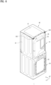
- FIG. 1 is a perspective view showing the external appearance of a laundry treating apparatus 1 according to an embodiment of the present disclosure.
- the embodiment of the present disclosure includes a cabinet 10.
- the cabinet 10 may define the external appearance of the laundry treating apparatus 1, and may have a space defined therein to accommodate various components.
- the drum 60 may be provided in the tub 65 to receive laundry.
- the drum 60 may include a drum opening that is open toward the laundry opening 28 and the tub opening. The laundry having passed through the laundry opening 28 and the tub opening may be loaded and received in the drum 60 through the drum opening.
- the embodiment of the present disclosure may include a detergent supply unit 72.
- the detergent supply unit 72 may store detergent and may supply the detergent to the interior of the tub 65 as necessary during the laundry washing process.
- the embodiment of the present disclosure may include an air supply unit 80 to supply air for the drying process to the interior of the drum 60 in which laundry is received.
- the air supply unit 80 may be configured to heat air in the drum 60, heat air introduced from the outside of the cabinet 10 and supply the heated air to the interior of the drum 60, or heat air in a circulation passage connected to the drum 60.
- the air supply unit 80 including the circulation passage may include a heat pump system to dehumidify or heat air discharged from the drum 60.
- a condenser or an evaporator of the heat pump system may be exposed to the circulation passage to dehumidify or heat the air.
- the embodiment of the present disclosure may include the primary treating apparatus and the supplementary treating apparatus 90 that may perform laundry treating processes independently of each other.
- the primary treating apparatus may include the cabinet 10 and the drum 60 described above, and the supplementary treating apparatus 90 may include a supplementary cabinet 95 and a supplementary drum 99, which are distinguished from the primary treating apparatus.
- FIG. 5 illustrates a side view of the laundry treating apparatus 1 including the supplementary treating apparatus 90 according to an embodiment of the present disclosure.
- the drum 60 of the primary treating apparatus and the supplementary tub 97 and the supplementary drum 99 of the supplementary treating apparatus 90 are indicated by dotted lines.
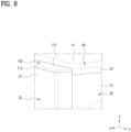
- FIGs. 7 and 8 show a cover panel 100 provided at the cabinet 10 according to an embodiment of the present disclosure.
- the cover panel 100 according to the embodiment of the present disclosure will now be described with reference to FIGs. 7 and 8 .
- the cover panel 100 may be disposed on the front panel 20.
- the cover panel 100 may be coupled to the front panel 20 to cover the front panel 20, thereby shielding a portion of the front panel 20 from the outside.
- a portion of the front panel 20 that is adjacent to another component, e.g., the top panel 40 may undergo a folding process or may have an opening formed therein.
- a gap or a clearance may be present between the front panel 20 and the top panel 40 or the like due to tolerance or the like, so the interior of the cabinet 10 may be exposed therethrough.
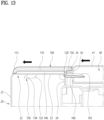
- FIG. 12 is a perspective view showing the cross-section of the cover panel 100 disposed on the front panel 20 according to an embodiment of the present disclosure when viewed from the front
- FIG. 13 is a cross-sectional view showing the cross-section shown in FIG. 12 when viewed in the lateral direction.
- the panel may include an upper surface portion 41 and a front protruding portion 43.
- the upper surface portion 41 may form the upper surface of the cabinet 10, and the front protruding portion 43 may protrude forward from the upper surface portion 41.
- the upper surface portion 41 may be provided to be substantially parallel to the ground.
- the front protruding portion 43 may be provided at the front side of the upper surface portion 41.
- the cover panel 100 disposed on the front panel 20 may be disposed in front of the top panel 40, and the front protruding portion 43 may protrude toward the cover panel 100 from the upper surface portion 41.
- the cover panel 100 may be disposed on the upper bent portion 22 to cover at least part of the upper bent portion 22 from the outside, and at least part of the front protruding portion 43 may be inserted into the rear side of the cover panel 100.
- the upper bent portion 22 of the front panel 20 may extend backward from the upper end of the front surface portion 21.
- the upper bent portion 22 may extend substantially parallel to the ground, and may extend toward the top panel 40 from the front surface portion 21.
- the cover panel 100 may be disposed on the upper bent portion 22.
- the cover panel 100 may form a coupling relationship with the upper bent portion 22.
- the cover panel 100 may be provided to cover the upper bent portion 22, thereby shielding at least part of the upper bent portion 22 from the outside.
- the cover panel 100 may extend in the lateral direction of the cabinet 10, and the extension length thereof in the lateral direction may be varied.
- the cover panel 100 may extend to have a shorter length than the upper bent portion 22, thereby shielding a part of the upper bent portion 22, or may extend to have a length equal to or longer than the length of the upper bent portion 22, thereby shielding the entirety of the upper bent portion 22.
- FIGs. 12 and 13 show the cover panel 100 that has a length corresponding to the length of the upper bent portion 22 in the forward-backward direction of the cabinet 10 to shield the entirety of the upper bent portion 22 according to an embodiment of the present disclosure.
- the front protruding portion 43 of the top panel 40 may be inserted into the cover panel 100. That is, the front protruding portion 43 of the top panel 40 may be inserted into the rear side of the cover panel 100, so a coupling relationship may be formed between the cover panel 100 and the top panel 40.
- the front protruding portion 43 of the top panel 40 is inserted into the rear side of the cover panel 100, backward movement of the cover panel 100 on the front panel 20 may be effectively restricted. Further, the phenomenon of the rear side of the cover panel 100 being lifted upward may be effectively suppressed due to the insertion relationship with the front protruding portion 43.
- the cover panel 100 may slide forward on the upper bent portion 22 to be coupled to the upper bent portion 22.
- the sliding direction of the cover panel 100 is conceptually indicated by arrows.
- the cover panel 100 may be coupled to the upper bent portion 22 of the front panel 20, and may slide during the coupling process. That is, after being placed on the upper bent portion 22, the cover panel 100 may slide forward to be coupled to the upper bent portion 22.
- the cover panel 100 may include a panel coupling portion 130 that is coupled to the upper bent portion 22 through a sliding process.
- a detailed description of the panel coupling portion 130 will be given later.
- backward movement of the cover panel 100 may be effectively restricted by the front protruding portion 43 of the top panel 40 that is inserted into the rear side of the cover panel 100.
- the top panel 40 may slide forward at a position behind the cover panel 100, and the front protruding portion 43 thereof may be inserted into the cover plate 100.
- the top panel 40 may be coupled and fixed to the side panel 30 of the cabinet 10.
- the top panel 40 may slide forward so as to be inserted into the cover panel 100 in the state of being supported by the side panel 30 or the like, and may then be coupled to the side panel 30 or the like. Alternatively, the top panel 40 may slide forward as a process for coupling with the side panel 30 or the like.
- the direction in which the top panel 40 slides as the coupling process of the top panel 40 according to an embodiment of the present disclosure is conceptually indicated by arrows. That is, in the embodiment of the present disclosure, the top panel 40 may slide forward to be coupled to the side panel 30 or the like. In this sliding process, the front protruding portion 43 may be naturally inserted into the rear side of the cover panel 100.
- front protruding portion 43 and the cover panel 100 are coupled to each other in the sliding process of the top panel 40, coupling force between the top panel 40 and the cover panel 100 may increase, and the cover panel 100 may be more strongly fixed.
- the top panel 40 may be located behind the cover panel 100.
- the upper surface portion 41 of the top panel 40 may be located behind the cover panel 100, and the top panel 40 may slide forward to be fixed.
- the top panel 40 may be located behind the cover panel 100 to restrict backward movement of the cover panel 100. Accordingly, as the front protruding portion 43 of the top panel 40 is inserted into the cover panel 100, lifting of the cover panel 100 may be prevented, a clearance may be effectively removed, and backward movement of the cover panel 100 may also be effectively restricted.
- the top panel 40 may include a front bent portion 42.
- the front bent portion 42 may extend downward from the front end of the upper surface portion 41 and may be located behind the cover panel 100 to support the cover panel 100 forward.
- the front bent portion 42 of the top panel 40 may be located behind the cover panel 100 to face the cover panel 100 forward, and may press and move the cover panel 100 forward, thereby coupling the cover panel 100 to the upper bent portion 22 or restricting backward movement of the cover panel 100 due to the contact relationship therewith.
- the front protruding portion 43 may protrude forward from the front bent portion 42 to be inserted into the cover panel 100 at a lower position than the upper surface portion 41.
- the front bent portion 42 may be formed by bending the front end portion of the upper surface portion 41 downward
- the front protruding portion 43 may be formed by bending the lower end portion of the front bent portion 42 forward.
- the front bent portion 42 and the front protruding portion 43 are not necessarily formed through the bending process.
- the front bent portion 42 may be spaced backward from the front end of the upper surface portion 41, and the front protruding portion 43 may be located at a higher position than the lower end of the front bent portion 42.
- the front protruding portion 43 in the case of forming the front protruding portion 43 by bending the front bent portion 42, there is an advantage of increasing ease of formation of the front protruding portion 43. Meanwhile, because the front protruding portion 43 extends forward from the front bent portion 42, the front protruding portion 43 may be inserted into the cover panel 100 at a lower position than the upper surface portion 41, whereby the coupling portion between the front protruding portion 43 and the cover panel 100 may be shielded from the outside by the cover panel 100 and the upper surface portion 41, and the occurrence of a clearance may be effectively suppressed.
- the cabinet 10 may further include a rear panel 50.
- the embodiment of the present disclosure may further include a top panel fixing member, which is coupled both to the top panel 40 and to the rear panel 50 at a position behind the top panel 40 to restrict backward movement of the top panel 40.
- the top panel fixing member is coupled both to the rear end of the top panel 40 and to the rear panel 50, thereby restricting backward movement of the top panel 40.
- the cover panel 100 located in front of the top panel 40 may also be restricted from moving backward, whereby a stable coupling structure may be implemented.
- the top panel fixing member may correspond to the above-described handle unit 300 or may be provided separately from the handle unit 300. A detailed description of the handle unit 300 will be given later.
- the cover panel 100 may include a cover upper surface portion 110.
- the cover upper surface portion 110 may be located in front of the upper surface portion 41 of the top panel 40 to form the upper surface of the cover panel 100.
- the cover upper surface portion 110 may include an upper surface parallel to the upper bent portion 22. That is, the cover upper surface portion 110 may define the upper surface of the cabinet 10 together with the upper surface portion 41 of the top panel 40. The upper surface of the cover upper surface portion 110 may be exposed to the outside instead of the upper bent portion 22 to form a part of the external appearance of the cabinet 10.
- the front protruding portion 43 may be located at a lower position than the cover upper surface portion 110 to be inserted into the cover panel 100, and thus may be shielded from the outside by the cover upper surface portion 110. That is, the front protruding portion 43 and the portion of the cover panel 100 into which the front protruding portion 43 is inserted may be located at a lower position than the cover upper surface portion 110.
- the front protruding portion 43 may be shielded from the outside by the cover upper surface portion 110, and the external appearance of the product may be improved by the cover upper surface portion 110 even when a coupling relationship is formed between the top panel 40 and the cover panel 100.
- the cover panel 100 may include a lower extension portion 120.
- the lower extension portion 120 may extend downward from the cover upper surface portion 110 and may be located behind the upper bent portion 22.
- the lower extension portion 120 may extend downward from the cover upper surface portion 110.
- the lower extension portion 120 may extend downward from the rear end of the cover upper surface portion 110 or may extend downward from a point in front of the rear end of the cover upper surface portion 110.
- the cover panel 100 may be formed to be longer than the upper bent portion 22 in the forward-backward direction of the cabinet 10. That is, the rear end of the cover panel 100 may be located at a position farther backward than the rear end of the upper bent portion 22.
- the lower extension portion 120 may be located behind the rear end of the upper bent portion 22. Accordingly, the lower extension portion 120 may extend such that the lower end thereof is located at a lower position than the upper bent portion 22.
- the front protruding portion 43 and/or the front bent portion 42 of the top panel 40 may be located behind the lower extension portion 120.
- the upper bent portion 22 may be located in front of the lower extension portion 120, and the front protruding portion 43 of the top panel 40 may be located behind the lower extension portion 120. Accordingly, the cover panel 100 may be restricted from moving forward due to contact between the lower extension portion 120 and the upper bent portion 22.
- cover panel 100 may be restricted from moving backward due to contact between the lower extension portion 120 and the front protruding portion 43. That is, the cover panel 100 may be fixed in position in the forward-backward direction due to the contact relationship between the upper bent portion 22, the lower extension portion 120, and the front protruding portion 43.
- the upper bent portion 22 may include a first upper bent portion 23 extending backward from the upper end of the front surface portion 21 and a second upper bent portion 24 extending downward from the rear end of the first upper bent portion 23.
- the cover panel 100 may be restricted from moving forward due to contact between the lower extension portion 120 and at least one of the first upper bent portion 23 or the second upper bent portion 24.
- the upper bent portion 22 may include a first upper bent portion 23 extending parallel to the ground and a second upper bent portion 24 extending from the first upper bent portion 23 substantially perpendicularly thereto.
- the lower end of the lower extension portion 120 may be located at the same height or lower than the first upper bent portion 23. That is, the front part of the lower extension portion 120 may have a contact relationship with the first upper bent portion 23 or the second upper bent portion 24.
- forward movement thereof may be restricted due to contact of the front part of the lower extension portion 120 with the rear end of the first upper bent portion 23, a part of the second upper bent portion 24, or a connection portion between the first upper bent portion 23 and the second upper bent portion 24.
- FIG. 14 shows the upper bent portion 22 to which the cover panel 100 is coupled in the embodiment of the present disclosure when viewed from below.
- the cover panel 100 may include a panel coupling portion 130, which is coupled to the upper bent portion 22 while penetrating the upper bent portion 22, and the upper bent portion 22 may include therein a coupling hole 25 through which the panel coupling portion 130 passes.
- the panel coupling portion 130 may be located at the front end of the coupling hole 25, so the cover panel 100 may be restricted from moving forward.
- the cover panel 100 may be fixed by coupling the panel coupling portion 130 to the upper bent portion 22. At least part of the panel coupling portion 130 may protrude downward from the cover panel 100. The panel coupling portion 130 may protrude downward from the cover upper surface portion 110 of the cover panel 100.
- the panel coupling portion 130 may be provided to penetrate the upper bent portion 22.
- the panel coupling portion 130 may be coupled to the first upper bent portion 23 while penetrating the first upper bent portion 23.
- the coupling hole 25 through which the panel coupling portion 130 passes may be formed in the upper bent portion 22.
- the coupling hole 25 may be formed in the first upper bent portion 23.
- Each of the panel coupling portion 130 and the coupling hole 25 may be provided in plural and may be disposed in the lateral direction of the cabinet 10.
- the panel coupling portion 130 may pass through the coupling hole 25, and accordingly, when the cover panel 100 is to be moved forward, forward movement of the cover panel 100 may be restricted by the panel coupling portion 130 contacting the periphery of the coupling hole 25.
- the coupling hole 25 may extend in the sliding direction of the cover panel 100, and the cover panel 100 may be coupled to the upper bent portion 22 as the panel coupling portion 130 slides forward in the state of passing through the coupling hole 25.
- the panel coupling portion 130 may move forward within the coupling hole 25.
- the panel coupling portion 130 may no longer move forward due to the shape of the coupling hole 25. In this way, forward movement of the cover panel 100 may be restricted.
- the panel coupling portion 130 may have various shapes and may be coupled to the upper bent portion 22 in various ways. Detailed characteristics of the panel coupling portion 130 will be described later.
- FIGs. 10 and 11 show a panel support portion 140 provided on the lower surface of the cover upper surface portion 110
- FIG. 13 shows the panel support portion 140 supporting the cover upper surface portion 110 in the state of being located on the upper bent portion 22 when viewed in the lateral direction.
- the cover panel 100 may include the above-described cover upper surface portion 110.
- the cover upper surface portion 110 may form the upper surface of the front panel 20.
- the cover upper surface portion 110 may be located in front of the upper surface portion 41 of the top panel 40 to form the upper surface of the cover panel 100.
- the cover panel 100 may include a panel support portion 140.
- the panel support portion 140 may protrude toward the upper bent portion 22 from the cover upper surface portion 110 to be supported by the upper bent portion 22.
- the panel support portion 140 of the cover panel 100 may be supported upward by the upper bent portion 22, and may support the cover upper surface portion 110.
- the panel support portion 140 may protrude downward from the lower surface of the cover upper surface portion 110.
- the panel support portion 140 may have a shape of a rib extending in the sliding direction of the cover panel 100. That is, the panel support portion 140 may extend entirely in the forward-backward direction to support the cover upper surface portion 110 from the upper bent portion 22 in the forward-backward direction.
- the panel support portion 140 may be provided in plural and may be disposed in the width direction of the cabinet 10.
- the panel support portion 140 protruding toward the upper bent portion 22 from the cover upper surface portion 110 is supported by the upper bent portion 22, sliding may be facilitated, and contact with the upper bent portion 22 and support thereby may be uniform and stable.
- the front end portion 112 of the cover upper surface portion 110 may be bent or curved toward the upper bent portion 22, thereby shielding at least part of the panel support portion 140 from the front.
- the front end of the cover upper surface portion 110 has a shape bent or curved downward, the front end of the cover upper surface portion 110 may be located in contact with or adjacent to the front end of the upper bent portion 22. Accordingly, the panel support portion 140 protruding downward from the cover upper surface portion 110 may be shielded from the front due to the shape of the front end portion 112 of the cover upper surface portion 110, and the clearance between the cover panel 100 and the front panel 20 may be minimized.
- the front end of the cover upper surface portion 110 which is curved downward, may be supported upward by the upper bent portion 22, and thus an area in which the cover upper surface portion 110 is supported may be effectively increased, and structural stability of the cover upper surface portion 110 may be improved.
- FIG. 15 shows a rear insertion groove 150 in the cover panel 100, into which the front protruding portion 43 is inserted, and a protruding support portion 165 of the cover panel 100 according to an embodiment of the present disclosure.
- FIG. 9 shows the protruding support portion 165 of the cover panel 100 when viewed from above.
- the front protruding portion 43 may be inserted into the rear insertion groove 150 from the rear.
- the rear insertion groove 150 may include a space into which the front protruding portion 43 is inserted.
- the rear insertion groove 150 may be open backward to allow the front protruding portion 43 to be inserted thereinto from the rear.
- the protruding support portion 165 may protrude toward the front protruding portion 43 from the bottom surface of the rear insertion groove 150.
- the width of the rear insertion groove 150 may be formed to be greater than the thickness of the front protruding portion 43 in consideration of ease of coupling.
- the width of the rear insertion groove 150 is formed to be greater than the thickness of the front protruding portion 43, the rear end portion of the cover panel 100 may be lifted due to a clearance between the front protruding portion 43 and the inner surface of the rear insertion groove 150.
- the cover panel 100 is allowed to move in the upward-downward direction by the clearance between the inner surface of the rear insertion groove 150 and the front protruding portion 43, it may be disadvantageous in terms of fixing of the cover panel 100 and removal of the clearance.
- the cover panel 100 may include a protruding support portion 165.
- the protruding support portion 165 may protrude upward from the bottom surface of the rear insertion groove 150.
- the bottom surface of the rear insertion groove 150 may be a surface located below the front protruding portion 43 among inner surfaces of the insertion groove 219.
- the protruding support portion 165 may protrude upward from the bottom surface of the rear insertion groove 150 to be in contact with the lower surface of the front protruding portion 43. That is, in the embodiment of the present disclosure, the distance by which the rear end portion of the cover panel 100 is allowed to move upward due to the relationship with the front protruding portion 43 may be minimized due to the protruding support portion 165 protruding upward from the bottom surface of the rear insertion groove 150.
- lifting of the cover panel 100 may be effectively minimized due to close contact between the front protruding portion 43 inserted into the rear insertion groove 150 and the protruding support portion 165. That is, upward movement of the cover panel 100 may be restricted by contact between the protruding support portion 165 and the front protruding portion 43.
- the protruding support portion 165 may extend in the sliding direction of the cover panel 100 and the top panel 40, i.e., the forward-backward direction, and may be provided in plural to be spaced apart from each other in the width direction of the cabinet 10.
- the protruding support portion 165 may be formed such that the rear end thereof has the lowest protruding height in order to facilitate insertion of the front protruding portion 43. That is, the protruding support portion 165 may be formed such that at least part thereof including the rear end gradually decreases in protruding height in the backward direction.
- the cover panel 100 may include a cover upper surface portion 110, a rear extension portion 160, and a protruding support portion 165.
- the rear extension portion 160 may be spaced downward from the cover upper surface portion 110 so that the front protruding portion 43 is inserted into a gap between the rear extension portion 160 and the cover upper surface portion 110.
- the rear extension portion 160 may be located at a lower position than the cover upper surface portion 110. That is, the rear extension portion 160 may be located at a lower position than the lower surface of the cover upper surface portion 110.
- the protruding support portion 165 may protrude toward the front protruding portion 43 from the rear extension portion 160.
- the rear extension portion 160 may extend backward from the lower extension portion 120, and the front protruding portion 43 may be inserted toward the lower extension portion 120 between the cover upper surface portion 110 and the rear extension portion 160.
- the rear extension portion 160 may extend substantially parallel to the lower surface of the cover upper surface portion 110, and the rear end of the rear extension portion 160 may be located at a position farther backward than the rear end of the cover upper surface portion 110.
- the rear extension portion 160 and the cover upper surface portion 110 may be spaced apart from each other, and the front protruding portion 43 may be inserted therebetween.
- the above-described rear insertion groove 150 may be formed between the rear extension portion 160 and the cover upper surface portion 110.
- the rear insertion groove 150 in the cover panel 100 may be defined by the lower surface of the cover upper surface portion 110, the rear surface of the lower extension portion 120, and the upper surface of the rear extension portion 160.
- the front protruding portion 43 inserted into the rear insertion groove 150 may face the cover upper surface portion 110 in the upward direction, may face the lower extension portion 120 in the forward direction, and may face the rear extension portion 160 in the downward direction.
- the contact area between the cover panel 100 and the front protruding portion 43 may be effectively increased, and lifting of the cover panel 100 may be effectively prevented.
- the cover panel 100 may include a panel coupling portion 130, and the panel coupling portion 130 may include a coupling body portion 132 and a coupling extension portion 134. That is, the cover panel 100 may include a coupling body portion 132, which protrudes downward from the cover panel 100 to penetrate the upper bent portion 22, and a coupling extension portion 134, which extends from the coupling body portion 132 in a direction intersecting the longitudinal direction of the coupling body portion 132 and is located below the upper bent portion 22.
- the coupling body portion 132 may extend so as to protrude downward from the cover panel 100, e.g., the cover upper surface portion 110.
- the coupling body portion 132 may pass through the above-described coupling hole 25 in the upper bent portion 22. That is, when the cover panel 100 is placed on the upper bent portion 22, the coupling body portion 132 may be located in the coupling hole 25.
- the coupling extension portion 134 may extend so as to protrude from the coupling body portion 132.
- the protruding direction or the extension direction of the coupling extension portion 134 may be a direction intersecting the extension direction of the coupling body portion 132.
- the coupling body portion 132 may extend toward the ground from the cover upper surface portion 110, and the coupling extension portion 134 may extend parallel to the ground.
- the coupling extension portion 134 may extend in the forward-backward direction or the width direction of the cabinet 10.
- the coupling extension portion 134 extending in a direction intersecting the longitudinal direction of the coupling body portion 132, which extends so as to pass through the coupling hole 25 in the upper bent portion 22, may be at least partially located below the upper bent portion 22. That is, at least part of the coupling extension portion 134 may be located below the upper bent portion 22 so as to deviate from the coupling hole 25.
- the coupling extension portion 134 located below the upper bent portion 22 may come into contact with the upper bent portion 22, thereby restricting upward movement of the cover panel 100.
- the upper bent portion 22 may include therein a coupling hole 25 through which the coupling body portion 132 passes, the coupling hole 25 may extend in the forward-backward direction to allow the coupling body portion 132 to slide therealong, and the coupling extension portion 134 may extend forward from the coupling body portion 132 so as to pass through the coupling hole 25.
- the extension direction of the coupling extension portion 134 and the extension direction of the coupling hole 25 may be identical to each other.
- at least a portion of the coupling hole 25 may be open with a larger area than the coupling extension portion 134. Accordingly, the coupling extension portion 134 may pass through at least a portion of the coupling hole 25 and may be located below the upper bent portion 22, i.e., the first upper bent portion 23.
- both the coupling extension portion 134 and the coupling hole 25 may extend in the forward-backward direction. Accordingly, in the process of placing the cover panel 100 on the upper bent portion 22, the coupling extension portion 134 may pass through the coupling hole 25 to be located below the upper bent portion 22.
- the coupling extension portion 134 extending forward from the coupling body portion 132 may be located below the upper bent portion 22 at a position deviating from the coupling hole 25. Accordingly, when the cover panel 100 is to be moved upward, upward movement of the cover panel 100 may be restricted due to contact between the coupling extension portion 134 and the upper bent portion 22.
- the cover panel 100 may include a rear extension portion 160 extending backward to be located below a portion of the top panel 40.
- the top panel 40 may include an upper surface portion 41 forming the upper surface of the cabinet 10, and a top panel space in which the rear end of the rear extension portion 160 is located may be defined under the upper surface portion 41.
- the top panel space may be open downward under the upper surface portion 41 to communicate with an inner space in the cabinet 10.
- a front bent portion 42 of the top panel 40 may be located at the front side of the top panel space
- a lateral bent portion 45 of the top panel 40 may be located at each of both lateral sides of the top panel space
- a rear bent portion 49 of the top panel 40 may be located at the rear side of the top panel space.
- the surfaces of the top panel space except the bottom surface thereof may be defined by the upper surface portion 41 and the bent portions of the top panel 40. A detailed description of the top panel space will be given later.
- the rear end of the rear extension portion 160 of the cover panel 100 may be located at a position farther backward than the front bent portion 42 to be disposed in the top panel space.
- the rear extension portion 160 may extend backward from the cover panel 100 at a position below the front bent portion 42 or may extend while penetrating the front bent portion 42.
- the lower end of the front bent portion 42 and the front protruding portion 43 may be located above the rear extension portion 160, or as shown in FIG. 13 , the lower end of the front bent portion 42 may be located below the rear extension portion 160, and the front bent portion 42 may have formed therein a hole through which the rear extension portion 160 passes.
- the rear extension portion 160 may extend backward from the lower extension portion 120 to be located below a portion of the top panel 40.
- the rear extension portion 160 may be spaced downward from the cover upper surface portion 41 to form the rear insertion groove 150 together with the cover upper surface portion 41, into which the front protruding portion 43 is inserted.
- the cabinet 10 may include a front panel 20 forming the front surface of the cabinet 10 and a top panel 40 forming the upper surface of the cabinet 10.
- the top panel 40 includes an upper surface portion 41 defining the upper surface, and the upper surface portion 41 is disposed at a higher position than the upper end of the front panel 20.
- FIGs. 5 and 8 show the structure of the cabinet 10 in which the upper surface portion 41 of the top panel 40 is located at a higher position than the upper end of the front panel 20 according to an embodiment of the present disclosure.
- Exterior finish of the cabinet 10 is an important factor for protecting the interior of the cabinet 10 and improving user satisfaction with the external appearance of the cabinet 10.
- the top panel 40 may have a stereoscopic structure so that the exterior completeness of the cabinet 10 is improved and the exterior finish of the cabinet 10 is effectively implemented.
- the top panel 40 may have a three-dimensional shape having a height in a direction perpendicular to the ground. Accordingly, the upper surface portion 41 of the top panel 40 that defines the upper surface of the cabinet 10 may be located at a higher position than the front panel 20.
- top panel 40 is formed in a two-dimensional plate shape, a coupling element used for coupling between the top panel 40 and the side panel 30 may be exposed to the outside as is, and the strength of the top panel 40 may be lowered, leading to deformation of the top panel 40 or deterioration in protection of the interior of the cabinet 10.
- the top panel 40 may have a three-dimensional shape with a certain height due to the plurality of bent portions, such as the front bent portion 42, the lateral bent portion 45, and the rear bent portion 49, so the strength of the top panel 40 may be effectively increased, and the exterior completeness of the top panel 40 may be effectively improved.
- the cabinet 10 may further include a side panel 30 forming the side surface of the cabinet 10, and the upper surface portion 41 may be disposed at a higher position than the side panel 30. That is, the upper end of the front panel 20 may be disposed at a higher position than the upper end of the side panel 30 and may be located in front of the top panel 40.
- the upper end of the front panel 20 may be located at a higher position than the upper end of the side panel 30. Accordingly, the front portion of the top panel 40 having a certain height may be effectively shielded and supported by the front panel 20.
- the top panel 40 may include a lateral bent portion 45 extending downward from each of both lateral sides of the upper surface portion 41, and the lateral bent portion 45 may be supported on the side panel 30.
- the coupled portion of the top panel 40 may be conveniently shielded from the outside due to coupling between the lateral bent portion 45 and the side panel 30.
- the front panel 20 may include a front surface portion 21 forming the front surface of the cabinet 10 and an upper bent portion 22 extending backward from the upper end of the front surface portion 21, and the upper surface portion 41 of the top panel 40 may be located at a higher position than the upper bent portion 22.
- the upper bent portion 22 of the front panel 20 may be located in front of or at a lower position than the front bent portion 42 of the top panel 40.
- the cabinet 10 may further include a cover panel 100 disposed on the upper bent portion 22 to cover at least part of the upper bent portion 22 from the outside, and the upper surface portion 41 may be located parallel to the cover panel 100.
- the upper end of the front panel 20 may be located at a lower position than the upper surface portion 41.
- the front portion of the top panel 40 may form a support structure together with the front panel 20, and the lower portion of the top panel 40 may form a support structure together with the side panel 30, thereby improving structural stability.
- the exterior finish of the upper side of the cabinet 10 is important.
- the cover panel 100 may be disposed on the front panel 20, and the top panel 40 may be formed to have a certain thickness.
- the top panel 40 may include a front bent portion 42 extending downward from the front end of the upper surface portion 41, and the upper bent portion 22 and the cover panel 100 may be located in front of the front bent portion 42.
- the top panel 40 may include a top panel space 44 defined under the upper surface portion 41, and the upper end of the front panel 20 may be located in front of the top panel space 44.
- the top panel 40 may include a plurality of bent portions extending downward from the upper surface portion 41, and the top panel space 44 may be surrounded by the plurality of bent portions and may be open downward.
- the cabinet 10 may further include a cover panel 100 disposed on the front panel 20, and at least a portion of the cover panel 100 may protrude backward to be inserted into the top panel space 44.
- the lower surface of the top panel space 44 may be open so that the top panel space 44 and the interior of the cabinet 10 communicate with each other to define one space. Meanwhile, as described above, in order to facilitate insertion of the rear extension portion 160 of the cover panel 100, the front bent portion 42 of the top panel 40 may be formed to have a shorter extension length than the lateral bent portion 45 or to have a hole formed therein.
- the embodiment of the present disclosure may include a cabinet 10, a drum 60 provided in the cabinet 10 to receive laundry, and a supplementary treating apparatus 90, which includes a supplementary cabinet 95 disposed under the cabinet 10 to support the cabinet 10 and a supplementary drum 99 provided in the supplementary cabinet 95 to receive laundry.
- the cabinet 10 disposed on the supplementary cabinet 95 may include a front panel 20 forming the front surface of the cabinet 10 and a top panel 40 forming the upper surface of the cabinet 10, the top panel 40 may include an upper surface portion 41 defining the upper surface, and the upper surface portion 41 may be disposed at a higher position than the upper end of the front panel 20.
- the top panel 40 may be formed in a three-dimensional shape.
- the cabinet 10 may include a top panel 40 forming the upper surface of the cabinet 10 and may include a support surface 200 located below the top panel 40 to support the top panel 40.
- the support surface 200 may correspond to a surface located below the top panel 40 to support the top panel 40 and may be substantially parallel to the ground.
- the support surface 200 may be the entirety or a part of any of various components.
- the support surface 200 may be provided as a part of the side panel 30 or may correspond to a part of a reinforcement frame 250 to be described later.
- the support surface 200 may be manufactured as an independent component and may form a coupling relationship with the side panel 30 or the like.
- the top panel 40 may be disposed on the support surface 200 and may be coupled thereto in a sliding manner as described above.
- the support surface 200 may extend in the sliding direction of the top panel 40, e.g., the forward-backward direction.
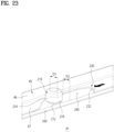
- the groove forming part 210 may be provided on the support surface 200 and may form an insertion groove 219 that is open in a direction parallel to the support surface 200. Accordingly, the top panel 40 may slide on the support surface 200 in a direction parallel to the support surface 200 so that a portion thereof is inserted into the insertion groove 219, and thus may be restricted from moving upward.
- the groove forming part 210 may be formed in a shape protruding upward from the support surface 200.
- the groove forming part 210 may correspond to a part of the support surface 200 or may be manufactured separately and coupled to the support surface 200.
- the groove forming part 210 may form an insertion groove 219 that is open in a direction parallel to the support surface 200.
- the insertion groove 219 may have a groove shape that is open in a direction parallel to the ground.
- the insertion groove 219 may be formed such that at least a portion thereof is open in the sliding direction of the top panel 40.
- the insertion groove 219 may be formed in the groove forming part 210 or may be formed in the relationship between the groove forming part 210 and another component.
- the insertion groove 219 may be defined by the groove forming part 210 and the support surface 200.
- FIG. 18 shows the cross-section of the insertion groove 219 defined by the support surface 200 and the groove forming part 210 according to an embodiment of the present disclosure.
- the top panel 40 may be partially inserted into the insertion groove 219 through sliding movement in the state of being supported on the support surface 200. Considering the structure of the groove, the top panel 40 partially inserted into the insertion groove 219 may be restricted from moving upward.
- the depth to which a portion of the top panel 40 is inserted into the insertion groove 219 may be structurally determined, and accordingly, the sliding distance of the top panel 40 may also be determined.
- the top panel 40 due to the structure in which the top panel 40 slides on the support surface 200 and is inserted into the insertion groove 219, movement of the top panel 40 in the upward-downward direction as well as the sliding direction may be restricted, and thus the top panel 40 may be fixed at the coupling position.
- the process of coupling the top panel 40 in the forward-backward direction and the process of coupling the top panel 40 in the upward-downward direction may not be performed separately, and the top panel 40 may be conveniently coupled and fixed in at least two directions only through sliding movement.
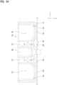
- the support surface 200 may be disposed on each of both sides of the cabinet 10 in the lateral direction and may extend in the forward-backward direction of the cabinet 10, and the top panel 40 may slide in the forward-backward direction.
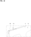
- FIG. 19 shows a structure in which the support surface 200 is connected to the upper end of a side panel 30 according to an embodiment of the present disclosure.
- the cabinet 10 may further include a side panel 30 disposed on each of both sides thereof in the lateral direction, the side panel 30 may include a side surface portion 31 forming the side surface of the cabinet 10, and the support surface 200 may extend toward the interior of the cabinet 10 from the upper end of the side surface portion 31.
- the support surface 200 may be formed by bending the upper end of the side panel 30. That is, the side panel 30 may include the side surface portion 31 and the support surface 200. In the embodiment of the present disclosure, because the support surface 200 is formed by bending the upper end portion of the side panel 30, the support surface 200 may stably support the top panel 40 and may have a shape extending in the sliding direction of the top panel 40.
- FIG. 20 shows a reinforcement frame 250 provided adjacent to the side panel 30 according to an embodiment of the present disclosure.
- the embodiment of the present disclosure may include a reinforcement frame 250, which is located below the top panel 40, is provided on each of both sides of the cabinet 10 in the lateral direction, and extends in the forward-backward direction.
- the support surface 200 may correspond to the upper surface of the reinforcement frame 250. That is, the groove forming part 210 may be coupled to the upper surface of the reinforcement frame 250. In this case, the upper end portion of the side panel 30 may be bent to cover the upper surface of the reinforcement frame 250 as needed.
- the support surface 200 may correspond to the bent upper end portion of the side panel 30 or the upper surface of the reinforcement frame 250.
- the groove forming part 210 may be coupled to the upper end portion of the side panel 30, may be coupled to the reinforcement frame 250, or may penetrate the upper end portion of the side panel 30 to be coupled to the reinforcement frame 250.
- FIG. 20 shows, as an example of the present disclosure, a structure in which the upper end portion of the side panel 30 is bent to form the support surface 200, the reinforcement frame 250 is located below the support surface 200, and the groove forming part 210 penetrates the support surface 200 to be coupled to the reinforcement frame 250.
- the support surface 200 will be described below as being a part of the side panel 30 that is connected to the upper end of the side surface portion 31 of the side panel 30 and is parallel to the ground, unless stated otherwise.
- the reinforcement frame 250 may extend in the forward-backward direction to form a coupling relationship with the front panel 20 and the rear panel 50, thereby increasing the rigidity of the cabinet 10.
- the reinforcement frame 250 may correspond to a reinforcement body supporting the support surface 200 from below.
- the support surface 200 may define the bottom surface of the insertion groove 219, and the remaining portion of the insertion groove 219 except the bottom surface may be defined by the groove forming part 210.
- the lower end of the insertion groove 219 may have the same height as the support surface 200, and accordingly, a portion of the top panel 40 sliding on the support surface 200 may be easily inserted into the insertion groove 219 without interference with a stepped portion.
- the groove forming part 210 may include a groove protruding portion 212 and an enlarged diameter portion 214.
- the groove protruding portion 212 may protrude upward from the support surface 200, and the enlarged diameter portion 214 may be located on the groove protruding portion 212 and may have a larger diameter D1 than the groove protruding portion 212.
- the groove protruding portion 212 may have various diameters D2. However, it is preferable that the diameter D2 of the groove protruding portion 212 be equal to or less than the width of the support surface 200 in the width direction of the cabinet 10.
- the groove forming part 210 may have the insertion groove 219 formed around the groove protruding portion 212 by the enlarged diameter portion 214 located on the groove protruding portion 212.
- the insertion groove 219 may be formed between the enlarged diameter portion 214 and the support surface 200. A portion of the top panel 40 may move toward the groove protruding portion 212 to be inserted into the insertion groove 219.
- the height of a lower surface 215 of the enlarged diameter portion 214 that faces the support surface 200 from the support surface 200 may gradually increase in a direction away from the groove protruding portion 212.
- the lower surface 215 of the enlarged diameter portion 214 may be a surface inclined so as to gradually approach the support surface 200 in a direction approaching the center of the groove forming part 210.
- the height of the entrance of the insertion groove 219 into which the top panel 40 is inserted may increase, so a portion of the top panel 40 sliding along the support surface 200 may be easily inserted.
- the top panel 40 may include an insertion portion 230 formed to be inserted into the insertion groove 219, and may slide from a preliminary position P1 to the coupling position P2 on the support surface 200.
- the insertion portion 230 may be spaced apart from the insertion groove 219 at the preliminary position P1 of the top panel 40, and may be inserted into the insertion groove 219 at the coupling position P2 of the top panel 40.
- the preliminary position P1 and the coupling position P2 of the top panel 40 are conceptually shown in FIG. 7 described above.
- the preliminary position P1 of the top panel 40 is a position at which the top panel 40 is disposed on the support surface 200 and is ready to slide before a portion thereof is inserted into the insertion groove 219.
- the coupling position P2 of the top panel 40 is a position at which a portion of the top panel 40 is completely inserted into the insertion groove 219 after sliding from the preliminary position P1. That is, in the embodiment of the present disclosure, the top panel 40 may slide from the preliminary position P1 disposed on the support surface 200 and then may reach the coupling position P2 at which a portion thereof is inserted into the insertion groove 219.
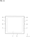
- FIG. 21 is a bottom view of the top panel 40.
- the top panel 40 may include an upper surface portion 41, a first bent portion 46, and a second bent portion 47.
- the upper surface portion 41 may form the upper surface of the cabinet 10
- the first bent portion 46 may extend downward from the upper surface portion 41
- the second bent portion 47 may extend parallel to the support surface 200 toward the interior of the cabinet 10 from the first bent portion 46.
- the open portion 240 may decrease in width at the insertion portion 230. That is, when the insertion portion 230 is inserted into the insertion groove 219, the width D4 of the open portion 240 may be less than the maximum diameter D1 of the groove forming part 210 in order to prevent the groove forming part 210 from passing through the open portion 240.
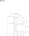
- the user may access the handle unit 300 through the space present above the top panel 40 of the cabinet 10 and may remove the handle fastening member 391 upward from the handle unit 300.
- the user may conveniently remove the handle fastening member 391, thereby efficiently releasing coupling between the upper portion 310 and the lower portion 350.
- the top panel 40 may include the upper surface portion 41 and the rear bent portion 49 described above.
- the upper portion 310 may be coupled to the rear bent portion 49 at the rear of the top panel 40.
- the handle unit 300 may be provided in plural as needed.
- the top panel coupling surface 320 may face the top panel 40 and may be coupled to the top panel 40.
- the top panel coupling surface 320 may face the rear bent portion 49 of the top panel 40 and may be coupled to the rear bent portion 49.
- a space may be defined between the top panel coupling surface 320 and the upper coupling surface 330. Through this space, the top panel coupling surface 320 may be exposed backward, and the upper coupling surface 330 may be exposed upward.
- the upper end of the handle fastening member 391, e.g., the head portion of the handle fastening member 391, may be located in the aforementioned space.
- the upper portion 310 may include a connection rib interconnecting the top panel coupling surface 320 and the upper coupling surface 330.
- the connection rib may be provided in plural to be spaced apart from each other in the lateral direction of the cabinet 10.
- the lower portion 350 may include a holding surface 360 and a lower coupling portion 372.
- the holding surface 360 may be disposed at the lower end of the lower portion 350 and may be held by the user.
- the lower coupling portion 372 may protrude upward from the holding surface 360 to be coupled to the upper portion 310.
- the holding surface 360 may be spaced downward from the upper coupling surface 330 of the upper portion 310.
- the holding surface 360 may be formed to be substantially parallel to the upper coupling surface 330.
- the holding surface 360 may be provided as a portion that the user may hold with his/her fingers in order to transport the cabinet 10.
- the lower coupling portion 372 may protrude toward the upper portion 310 from the holding surface 360.
- the lower coupling portion 372 may extend upward from the holding surface 360 to support the upper coupling surface 330 of the upper portion 310.
- the lower coupling portion 372 may be provided in plural.
- the lower coupling portions 372 may be spaced apart from each other in the lateral direction of the cabinet 10.
- the lower portion 350 may further include sidewalls disposed at the outermost sides thereof in the lateral direction.
- the lower portion 350 may include a rear panel coupling surface formed to be coupled to the rear panel 50.
- the rear panel coupling surface may be located substantially below the top panel coupling surface 320 of the upper portion 310.
- the rear panel coupling surface and the top panel coupling surface 320 may be located parallel to each other.
- the rear panel coupling surface and the holding surface 360 may have shapes bent relative to each other.
- the rear panel coupling surface and the holding surface 360 may correspond to surfaces formed to be bent relative to each other.
- the sidewalls and the lower coupling portions 372 described above may be connected to the holding surface 360 and the rear panel coupling surface to interconnect the two surfaces. That is, the lower coupling portions 372 and the sidewalls of the lower portion 350 may interconnect the rear panel coupling surface and the holding surface 360, thereby increasing the structural rigidity of the lower portion 350.
- the convex portion 361 may have a shape protruding downward from the holding surface 360, and the concave portion 362 may have a shape depressed upward in the holding surface 360.
- the convex portion 361 and the concave portion 362 may form a wave shape.
- the holding surface 360 may provide an area that may be held by the user, and accordingly, the convex portions 361 and the concave portions 362 may be formed on the holding surface 360 so that the user conveniently places his/her fingers thereon.
- the upper portion 310 may have a larger width D5 than the lower portion 350, and may be seated on the upper portion 310. That is, the width D5 of the upper portion 310 may be larger than the width D6 of the lower portion 350 based on the lateral direction of the cabinet 10.
- the user may lift the upper portion 310 from the lower portion 350 in order to lift the top panel 40.
- the upper portion 310 may function as a handle by itself.
- the width D5 of the upper portion 310 may be larger than the width D6 of the lower portion 350 so that the user easily holds the upper portion 310 excluding the lower portion 350.
- At least one of both end portions of the upper portion 310 may protrude outward from the lower portion 350 in the lateral direction of the cabinet 10, and this protruding portion may allow the user to conveniently hold the upper portion 310 separately from the lower portion 350.
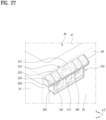
- FIG. 33 shows a state in which the handle unit 300 is separated from the cabinet 10 and the upper portion 310 and the lower portion 350 are separated from each other.
- the upper portion 310 may include an upper guide portion 321 protruding toward the top panel 40, and the top panel 40 may include an upper guide insertion portion 322 and 230 into which the upper guide portion 321 is inserted.
- the upper guide portion 321 may protrude forward from the top panel coupling surface 320 or the upper coupling surface 330 of the upper portion 310.
- the upper guide portion 321 may be formed in a pillar or protrusion shape having various cross-sectional shapes.
- the upper guide portion 321 may protrude forward from the top panel coupling surface 320 facing the rear bent portion 49 of the top panel 40.
- the rear bent portion 49 of the top panel 40 may include an upper guide insertion portion 322 and 230 into which the upper guide portion 321 is inserted.
- Coupling of the upper portion 310 to the top panel 40 may be completed by inserting the upper guide portion 321 into the upper guide insertion portion 322 and 230 or may be completed using the above-described upper portion fastening member 392 in the state in which the upper guide portion 321 is inserted into the upper guide insertion portion 322 and 230.
- the handle unit 300 may include the upper portion fastening member 392 that penetrates the upper portion 310 and is inserted into the top panel 40, and the upper portion 310 may be fixed to the top panel 40 by the upper portion fastening member 392.
- the upper guide portion 321 may serve to guide a coupling position for coupling of the upper portion 310 to the top panel 40.
- the upper portion 310 may be temporarily secured at the coupling position as the upper guide portion 321 is inserted into the upper guide insertion portion 322 and 230.
- the upper portion fastening member 392 may penetrate the upper portion 310 and may be fastened to the rear bent portion 49, whereby the upper portion 310 may be coupled to the rear bent portion 49.
- FIG. 33 shows a structure in which a pair of upper guide portions 321 is spaced apart from each other in the lateral direction of the cabinet 10 according to an embodiment of the present disclosure.
- the upper portion fastening member 392 may penetrate the upper portion 310 between the plurality of upper guide portions 321 and may be inserted into the top panel 40. For example, based on the lateral direction of the cabinet 10, the upper portion fastening member 392 may penetrate the substantially central portion of the top panel coupling surface 320 and may be coupled to the rear bent portion 49 of the top panel 40, and the upper guide portions 321 may be located on both sides of the upper portion fastening member 392.
- the coupling position of the upper portion 310 may be effectively guided by the upper guide portions 321 inserted into the upper guide insertion portion 322 and 230 of the rear bent portion 49. Further, although one upper portion fastening member 392 is used, unintended rotation of the upper portion 310 may be effectively prevented.
- the lower portion 350 may include a lower guide portion 381 protruding toward a part of the cabinet 10 except the top panel 40, and the part of the cabinet 10 except the top panel 40 may include a lower guide insertion portion 382 and 230 into which the lower guide portion 381 is inserted.
- the lower guide portion 381 may protrude forward from the lower portion 350.
- the features of the lower guide portion 381, e.g., the shape thereof, may be identical to the features of the above-described upper guide portion 321 unless otherwise specified.
- the lower guide portion 381 may protrude forward from the holding surface 360 or the rear panel coupling surface of the lower portion 350.
- FIG. 33 shows the lower guide portion 381 protruding forward from the rear panel coupling surface according to an embodiment of the present disclosure.
- the lower guide insertion portion 382 and 230 may be provided in the rear panel 50.
- the lower guide portion 381 may be inserted into the lower guide insertion portion 382 and 230.
- the lower guide portion 381 may be inserted into the lower guide insertion portion 382 and 230 so as to penetrate the same.
- Coupling of the lower portion 350 to the rear panel 50 may be completed by inserting the lower guide portion 381 into the lower guide insertion portion 382 and 230 or may be completed using the above-described lower portion fastening member 393 in the state in which the lower guide portion 381 is inserted into the lower guide insertion portion 382 and 230.
- the handle unit 300 may include the lower portion fastening member 393 that penetrates the lower portion 350 and is inserted into the rear panel 50, and the lower portion 350 may be fixed to the rear panel 50 by the lower portion fastening member 393.
- the lower guide portion 381 may serve to guide a coupling position for coupling of the lower portion 350 to the rear panel 50.
- the lower portion 350 may be temporarily secured at the coupling position as the lower guide portion 381 is inserted into the lower guide insertion portion 382 and 230.
- the lower portion fastening member 393 may penetrate the lower portion 350 and may be fastened to the rear panel 50, whereby the lower portion 350 may be coupled to the rear panel 50.
- FIG. 34 illustrates a top view of the lower portion 350, which is provided with an additional protruding portion 383.
- the lower portion 350 may include an additional protruding portion 383 protruding parallel to the lower guide portion 381.
- the additional protruding portion 383 may not be inserted into the part of the cabinet 10 except the top panel 40.
- the additional protruding portion 383 may not penetrate or form a coupling relationship with the above-described rear panel 50.
- the protruding end portion of the additional protruding portion 383 may merely support the rear panel 50 forward.
- the additional protruding portion 383 may protrude from the lower portion 350 so as to be parallel to the lower guide portion 381, and the protruding length thereof may be shorter than the lower guide portion 381. Accordingly, in the state in which the lower portion 350 is disposed adjacent to the rear side of the rear panel 50, the lower guide portion 381 may penetrate the rear panel 50 through the lower guide insertion portion 382 and 230, but the additional protruding portion 383 may not penetrate the rear panel 50 and may be located behind the rear panel 50.
- the additional protruding portion 383 may serve to increase the support force of the rear panel 50 for the rear panel coupling surface.
- the additional protruding portion 383 may be formed in various ways.
- the additional protruding portion 383 may be manufactured separately from the lower portion 350 and coupled to the lower portion 350, or may be formed simultaneously when the lower portion 350 is manufactured.
- the lower portion 350 may be manufactured by injecting an injection fluid into an injection mold having a space corresponding to the external appearance of the lower portion 350 and then curing the injection fluid, and the additional protruding portion 383 may be formed at a position corresponding to a gate of the injection mold, through which the injection fluid is injected, due to the presence of the gate.
- the injection quality of the lower portion 350 may be effectively improved by effectively increasing the number of gates.
- the handle unit 300 may include a lower portion fastening member 393 that penetrates the lower portion 350 between the lower guide portion 381 and the additional protruding portion 383 and is inserted into a part of the cabinet 10 except the top panel 40.
- FIG. 34 shows a structure in which the lower guide portion 381 and the additional protruding portion 383 are spaced apart from each other in the lateral direction of the cabinet 10 according to an embodiment of the present disclosure.
- the lower portion fastening member 393 may penetrate the lower portion 350 between the lower guide portion 381 and the additional protruding portion 383 and may be inserted into the rear panel 50.
- the lower portion fastening member 393 may penetrate the substantially central portion of the rear panel coupling surface and may be coupled to the rear panel 50, and the lower guide portion 381 or the additional protruding portion 383 may be located on each of both sides of the lower portion fastening member 393.
- the coupling position of the lower portion 350 may be effectively guided by the lower guide portion 381 inserted into the lower guide insertion portion 382 and 230 of the rear panel 50. Further, although one lower portion fastening member 393 is used, unintended rotation of the lower portion 350 may be effectively prevented.
- the handle unit 300 may include a holding space 302 depressed toward cabinet 10 on a surface thereof located opposite the cabinet 10.
- the handle unit 300 may have a holding space 302 defined therein.
- the holding space 302 may be open backward.
- the holding space 302 may be defined between the sidewall and the rear protruding portion of the above-described lower portion 350 and between the plurality of rear protruding portions.
- the user may hold the holding surface 360 of the handle unit 300, i.e., the bottom surface of the handle unit 300, with his/her fingers to lift at least a portion of the cabinet 10.
- the user when the user wants to separate the upper portion 310 and the lower portion 350 from each other and lift the top panel 40, the user may lift only the upper portion 310 separately from the lower portion 350. In this case, the user may insert his/her fingers into the holding space 302 to lift the upper portion 310.
- the handle unit 300 may include the holding space 302 in which the user's fingers are received in order to allow the user to easily hold the upper portion 310 when separating the upper portion 210 from the lower portion 350.
- the holding space 302 may correspond to a space in which the above-described lower portion fastening member 393 approaches and penetrates the rear panel coupling surface of the lower portion 350.
- the holding space 302 may be formed in the lower portion 350 so as to be open upward, and the upper portion 310 may be coupled to the lower portion 350 to shield the holding space 302 from above.
- the holding space 302 may be formed in the lower portion 350.
- the lower coupling portions 372 and/or the sidewalls of the lower portion 350 may be located on both sides of the holding space 302, the holding surface 360 may be located below the holding space 302, and the upper coupling surface 330 of the upper portion 310 may be located above the holding space 302.
- the holding space 302 may be open backward.
- the holding space 302 in the handle unit 300 may be defined by the upper coupling surface 330 of the upper portion 310, the sidewall and/or the lower guide portion 381 of the lower portion 350, the holding surface 360, and the rear panel coupling surface.
- the holding space 302 may be open backward to allow the user's fingers or the lower portion fastening member 393 to be inserted thereinto from the rear.
- the holding space 302 may be defined between the plurality of lower coupling portions 372 or between the sidewall and the lower coupling portion 372.
- the rear panel coupling surface may be located in front of the holding space 302, and the holding surface 360 may be located below the holding space 302.
- the holding space 302 may be open backward and upward.
- the open upper surface of the holding space 302 may be shielded by the upper coupling surface 330 of the upper portion 310 located on the lower portion 350.
- the holding space 302 may be provided in plural, and the lower coupling portion 372 may be disposed between the plurality of holding spaces 302. That is, the lower coupling portion 372 may protrude upward from the holding surface 360 to isolate the plurality of holding spaces 302 from each other.
- FIGs. 29 and 30 show a fastening guide portion 340 accommodated in the lower portion 350
- FIG. 33 shows the fastening guide portion 340 of the upper portion 310 separated from the lower portion 350.
- the fastening guide portion 340 may protrude downward from the upper portion 310 to be accommodated in the lower portion 350. During the process in which the upper portion 310 is coupled to the lower portion 350, the fastening guide portion 340 may guide the positions of the upper portion 310 and the lower portion 350.
- the fastening guide portion 340 may be provided in plural, and the number thereof may be varied.
- the upper coupling portion 332 of the upper portion 310 may be disposed between the plurality of fastening guide portions 340.
- the upper portion 310 may be guided to the coupling position by the fastening guide portions 340 in the process of being seated on the lower portion 350, and the upper coupling portion 332 defined between the plurality of fastening guide portions 340 may be effectively guided to the coupling position on the lower coupling portion 372.
- the fastening guide portion 340 may be accommodated in the holding space 302. That is, as described above, the holding space 302 may be defined in the lower portion 350 so as to be open upward, and the open upper surface of the holding space 302 may be shielded by the upper coupling surface 330 of the upper portion 310.
- the fastening guide portion 340 may extend downward from the upper coupling surface 330. That is, the fastening guide portion 340 may protrude downward from a portion of the upper coupling surface 330 that is located above the holding space 302 and may be inserted into the holding space 302.
- FIG. 30 illustrates a rear view of the fastening guide portion 340 inserted into the holding space 302.
- the width D7 of the holding space 302 may be larger than the width D8 of the fastening guide portion 340.
- the holding space 302 may correspond to a space into which the fastening guide portion 340 is inserted. Further, as described above, the holding space 302 may be a space in which to receive the user's fingers. Accordingly, the holding space 302 may have a width large enough to receive the fingers based on the lateral direction of the cabinet 10.
- the width D7 of the holding space 302 may be determined to be larger than the width D8 of the fastening guide portion 340 inserted into the holding space 302.
- the holding inner surface 304 may be provided thereon with an inner protruding portion 306, which extends parallel to the fastening guide portion 340 and is located adjacent to the fastening guide portion 340 to guide the position of the fastening guide portion 340.
- the inner protruding portion 306 may protrude backward from the holding inner surface 304, and may have a rib shape extending in the upward-downward direction so as to be parallel to the fastening guide portion 340.
- the inner protruding portion 306 may be located in contact with or adjacent to one sidewall of the fastening guide portion 340 located adjacent to the fastening guide portion 340.
- the inner protruding portion 306 may extend in the upward-downward direction and may be located adjacent to one of both sides of the fastening guide portion 340 based on the lateral direction of the cabinet 10. That is, the inner protruding portion 306 may restrict lateral movement of the fastening guide portion 340, thereby guiding the coupling position of the upper portion 310.
- the holding space 302 may have a larger width D7 than the fastening guide portion 340 for various reasons.
- the inner protruding portion 306 may be disposed adjacent to the fastening guide portion 340 in the lateral direction so that the position of the fastening guide portion 340 in the lateral direction is sufficiently restricted in the holding space 302.
- the lower portion 350 may include a plurality of holding spaces 302, and the plurality of holding spaces 302 may have different widths.
- the holding space 302 into which the fastening guide portion 340 is inserted may have a larger width than the fastening guide portion 340
- the holding space 302 into which the fastening guide portion 340 is not inserted may have a width that is equal to or smaller than the width of the fastening guide portion 340.
- FIG. 30 a plurality of holding spaces 302 having different widths is shown.
- the sidewall and the lower coupling portion 372 of the above-described lower portion 350 may be defined together as a partition wall, and the plurality of holding spaces 302 separated from each other by the partition wall may have different widths.
- FIG. 30 shows a structure in which the lower portion fastening member 393 is inserted into the holding space 302 defined between a pair of lower coupling portions 372 from the rear, the fastening guide portion 340 is inserted into the holding space 302 defined between the lower coupling portion 372 and the sidewall from above, and the holding space 302 into which the fastening guide portion 340 is inserted has a larger width than the holding space 302 into which the lower portion fastening member 393 is inserted.
- the inner protruding portion 306 may be provided only in the holding space 302 into which the fastening guide portion 340 is inserted. However, in the embodiment of the present disclosure, the width D7 of the holding space 302 may be varied, and an object that is inserted into the holding space 302 may also be varied.
- the embodiment of the present disclosure may include the supplementary treating apparatus 90.
- the supplementary treating apparatus 90 may include a supplementary cabinet 95 disposed under the cabinet 10 to support the cabinet 10 and a supplementary drum 99 provided in the supplementary cabinet 95 to receive laundry.
- the handle fastening member 391 may penetrate the upper portion 310 downward and may be removably inserted into the lower portion 350, whereby the coupling and separation relationships between the upper portion 310 and the lower portion 350 in the upward-downward direction may be effectively implemented.
Landscapes
- Engineering & Computer Science (AREA)
- Textile Engineering (AREA)
- Main Body Construction Of Washing Machines And Laundry Dryers (AREA)
- Detail Structures Of Washing Machines And Dryers (AREA)
Abstract
Description
- The present disclosure relates to a laundry treating apparatus, and more particularly, to a laundry treating apparatus capable of performing processes for treating laundry.
- A laundry treating apparatus is an apparatus that receives laundry, such as clothes and bedding, in a drum to perform treatment necessary for the laundry, such as removal of contaminants from the laundry or drying of the laundry.
- When a laundry treating apparatus is designed to remove contaminants from laundry, the laundry treating apparatus may perform processes such as washing, rinsing, dehydration, and drying. The laundry treating apparatus may be classified into a top loading type and a front loading type according to a method of loading laundry in a drum.
- The laundry treating apparatus may include a cabinet defining the external appearance thereof, a tub accommodated in the cabinet, a drum rotatably mounted in the tub and configured to receive laundry, and a detergent supply device configured to supply detergent to the interior of the drum.
- If the drum is rotated by a motor in a state in which wash water is supplied to the laundry received in the drum, dirt on the laundry may be removed by friction with the drum and the wash water.
- The detergent supply device has a detergent supply function in order to improve a washing effect. Here, the detergent refers to a substance for improving a washing effect, such as fabric detergent, fabric softener, and fabric bleach. Detergent in a powder form or detergent in a liquid form may be used as the detergent.
- On the other hand, when a laundry treating apparatus is designed to dry laundry, the laundry treating apparatus may supply dry air to the laundry to remove moisture from the laundry.
- The laundry treating apparatus may include a cabinet, a drum rotatably disposed in the cabinet, and a heating device configured to heat or dry air supplied to the laundry.
- As the dry air is supplied to the laundry received in the drum, moisture in the laundry may be evaporated and removed by the dry air, and thus water may be removed from the laundry.
- Meanwhile, a laundry treating apparatus constituted by multiple treating apparatuses is disclosed in related art document
KR 10-2007-0067466 A1 - In order to improve the convenience of use of the laundry treating apparatus, the multiple separate treating apparatuses may be disposed together in a stacked structure or the like to be provided to a user. The user may use each of the multiple treating apparatuses according to use conditions.
- Meanwhile, a laundry treating apparatus including a carrying handle for transportation of a cabinet is disclosed in related art document
KR 10-2000-0033470 A1 - The laundry treating apparatus including a tub and/or a drum may be provided therein with various components, and the carrying handle needs to have a structure that is efficiently coupled to the cabinet or the like in order to stably support the load of the laundry treating apparatus.
- In addition, inspection or repair of the various components may be required during use of the laundry treating apparatus. Therefore, at least some of a plurality of panels constituting the cabinet need to be easily separated from the cabinet so that a user or a worker is able to access the interior of the cabinet.
- Therefore, it is an important task in the present technical field to provide a coupling structure capable of stably enduring the load of a laundry treating apparatus for transportation of the laundry treating apparatus and to facilitate separation of at least some of a plurality of panels in order to secure access to the interior of the laundry treating apparatus.
- Embodiments of the present disclosure provide a laundry treating apparatus including a handle unit having a strong coupling structure so that the load of a cabinet is stably transmitted thereto.
- In addition, embodiments of the present disclosure provide a laundry treating apparatus capable of facilitating separation of at least some of a plurality of panels constituting a cabinet, thereby securing access to the interior of the cabinet.
- In addition, embodiments of the present disclosure provide a laundry treating apparatus including a handle unit constituted by a plurality of parts coupled to a plurality of panels with improved coupling force.
- In addition, embodiments of the present disclosure provide a laundry treating apparatus allowing access to a handle unit from above the handle unit, thereby securing ease of coupling or separation of the handle unit.
- In addition, embodiments of the present disclosure provide a laundry treating apparatus enabling efficient separation of at least some of a plurality of panels without separation of a handle unit from a cabinet.
- In addition, embodiments of the present disclosure provide a laundry treating apparatus, the convenience of use of which is improved and the coupling process of which is effectively improved.
- In addition, an embodiment of the present disclosure provides a laundry treating apparatus constituted by multiple treating apparatuses to provide improved use convenience.
- A laundry treating apparatus according to an embodiment of the present disclosure includes a handle unit coupled to a cabinet. The handle unit includes an upper portion and a lower portion. The upper portion and the lower portion are coupled to different panels to secure coupling force of the handle unit.
- The upper portion is separably coupled to the lower portion from above the lower portion. The upper portion may be separated upward from the lower portion. Because the upper portion is coupled to the top panel, the top panel may be separated from the cabinet in the state in which the upper portion is not separated from the top panel.
- The upper portion and the lower portion may be separably coupled to each other by means of a handle fastening member, and the handle fastening member may penetrate the upper portion from above the upper portion and may be coupled to the lower portion.
- The upper end of the handle fastening member may be exposed upward from the upper portion, and thus a worker may access the handle unit through a space present above the cabinet and may conveniently fasten or remove the handle fastening member.
- The laundry treating apparatus according to the embodiment of the present disclosure includes a cabinet, a drum, and a handle unit. The cabinet includes a top panel, the drum is provided in the cabinet to receive laundry, and the handle unit is coupled to the cabinet and is configured to be held by a user.
- The handle unit comprises an upper portion and a lower portion. The upper portion is coupled to the top panel so as to protrude therefrom, and the lower portion is located under the upper portion and is coupled to a part of the cabinet except the top panel so as to protrude therefrom. The upper portion is separably coupled to the lower portion from above the lower portion.
- The lower portion may include a lower coupling portion coupled to the upper portion, and the upper portion may include an upper coupling portion located on the lower coupling portion and coupled to the lower coupling portion from above.
- The handle unit may further include a handle fastening member configured to penetrate the upper portion downward to be removably inserted into the lower portion. The handle fastening member may be exposed upward from the upper portion.
- The cabinet may further include a rear panel, the lower portion may be coupled to the rear panel at the rear of the rear panel, and the upper portion may be coupled to the top panel at the rear of the top panel.
- The top panel may include an upper surface portion defining an upper surface of the cabinet and a rear bent portion extending downward from the rear end of the upper surface portion, and the upper portion may be coupled to the rear bent portion at the rear of the top panel.
- The upper portion may include an upper coupling surface located on the lower portion and coupled to the lower portion while facing the lower portion and a top panel coupling surface connected to the upper coupling surface and coupled to the top panel while facing the top panel.
- The lower portion may include a holding surface disposed at the lower end of the lower portion and formed to be held by a user and a lower coupling portion protruding upward from the holding surface to be coupled to the upper portion.
- A convex portion protruding downward and a concave portion depressed upward may be alternately arranged on the holding surface. The upper portion may have a larger width than the lower portion and may be seated on the upper portion.
- The upper portion may include an upper guide portion protruding toward the top panel, and the top panel may include an upper guide insertion portion into which the upper guide portion is inserted.
- The handle unit may further include an upper portion fastening member penetrating the upper portion to be inserted into the top panel. The upper guide portion may be provided in plural, and the upper portion fastening member may penetrate the upper portion between the plurality of upper guide portions and may be inserted into the top panel.
- The lower portion may include a lower guide portion protruding toward a part of the cabinet except the top panel, and the part of the cabinet except the top panel may include a lower guide insertion portion into which the lower guide portion is inserted.
- The lower portion may further include an additional protruding portion protruding parallel to the lower guide portion, and the additional protruding portion may not be inserted into the part of the cabinet except the top panel.
- The handle unit may further include a lower portion fastening member penetrating the lower portion between the lower guide portion and the additional protruding portion to be inserted into the part of the cabinet except the top panel.
- The handle unit may include a holding space depressed toward cabinet on a surface thereof located opposite the cabinet.
- The holding space may be defined in the lower portion so as to be open upward, and the upper portion may be coupled to the lower portion to shield the holding space from above.
- The holding space may be provided in plural, the lower portion may include a lower coupling portion coupled to the upper portion, and the lower coupling portion may be disposed between the plurality of holding spaces.
- The upper portion may include a fastening guide portion protruding downward to be accommodated in the lower portion.
- The fastening guide portion may be provided in plural, the upper portion may include an upper coupling portion coupled to the lower portion, and the upper coupling portion may be disposed between the plurality of fastening guide portions.
- The lower portion may include a holding space defined therein so as to be open upward, and the fastening guide portion may be accommodated in the holding space. The width of the holding space may be larger than the width of the fastening guide portion.
- The lower portion may include a holding inner surface having a larger width than the fastening guide portion and defining one surface of the holding space, and the holding inner surface may be provided thereon with an inner protruding portion extending parallel to the fastening guide portion and located adjacent to the fastening guide portion to guide the position of the fastening guide portion.
- The embodiment of the present disclosure may further include a supplementary treating apparatus including a supplementary cabinet disposed under the cabinet to support the cabinet and a supplementary drum provided in the supplementary cabinet to receive laundry.
- An embodiment of the present disclosure may include a cabinet including a top panel, a drum provided in the cabinet to receive laundry, and a handle unit coupled to the cabinet and configured to be held by a user, and the handle unit may include an upper portion coupled to the top panel so as to protrude therefrom, a lower portion coupled to a part of the cabinet except the top panel so as to protrude therefrom, and a handle fastening member configured to penetrate the upper portion downward to be removably inserted into the lower portion.
- Embodiments of the present disclosure may provide a laundry treating apparatus including a handle unit having a strong coupling structure so that the load of a cabinet is stably transmitted thereto.
- In addition, embodiments of the present disclosure may provide a laundry treating apparatus capable of facilitating separation of at least some of a plurality of panels constituting a cabinet, thereby securing access to the interior of the cabinet.
- In addition, embodiments of the present disclosure may provide a laundry treating apparatus including a handle unit constituted by a plurality of parts coupled to a plurality of panels with improved coupling force.
- In addition, embodiments of the present disclosure may provide a laundry treating apparatus allowing access to a handle unit from above the handle unit, thereby securing ease of coupling or separation of the handle unit.
- In addition, embodiments of the present disclosure may provide a laundry treating apparatus enabling efficient separation of at least some of a plurality of panels without separation of a handle unit from a cabinet.
- In addition, embodiments of the present disclosure may provide a laundry treating apparatus, the convenience of use of which is improved and the coupling process of which is effectively improved.
- In addition, an embodiment of the present disclosure may provide a laundry treating apparatus constituted by multiple treating apparatuses to provide improved use convenience.
-
-
FIG. 1 is a perspective view showing the external appearance of a laundry treating apparatus according to an embodiment of the present disclosure. -
FIG. 2 is a cross-sectional view showing the interior of a laundry treating apparatus according to an embodiment of the present disclosure in which a laundry washing process may be performed. -
FIG. 3 is a cross-sectional view showing the interior of a laundry treating apparatus according to an embodiment of the present disclosure in which a laundry drying process may be performed. -
FIG. 4 is a front perspective view of a laundry treating apparatus including a supplementary treating apparatus according to an embodiment of the present disclosure. -
FIG. 5 is a side view of the laundry treating apparatus including the supplementary treating apparatus in the embodiment of the present disclosure. -
FIG. 6 is a rear perspective view of the laundry treating apparatus including the supplementary treating apparatus in the embodiment of the present disclosure. -
FIG. 7 is a view showing a top panel coupling method in the laundry treating apparatus according to an embodiment of the present disclosure. -
FIG. 8 is a view showing a cover panel disposed on a front panel in the laundry treating apparatus according to an embodiment of the present disclosure. -
FIG. 9 is a top view of the cover panel in the laundry treating apparatus according to an embodiment of the present disclosure. -
FIG. 10 is a bottom view of the cover panel in the laundry treating apparatus according to an embodiment of the present disclosure. -
FIG. 11 is a bottom perspective view of the cover panel in the laundry treating apparatus according to an embodiment of the present disclosure. -
FIG. 12 is a perspective view showing the cross-section of the cover panel coupled to the front panel in the embodiment of the present disclosure. -
FIG. 13 is a cross-sectional view of the cover panel coupled to the front panel in the embodiment of the present disclosure. -
FIG. 14 is a bottom perspective view showing the cross-section of the cover panel coupled to the front panel in the embodiment of the present disclosure. -
FIG. 15 is a view showing a coupling structure between the cover panel and the top panel in the embodiment of the present disclosure. -
FIG. 16 is a view showing the cabinet with the top panel separated therefrom in the embodiment of the present disclosure. -
FIG. 17 is a view showing a groove forming part provided on a support surface of the cabinet in the embodiment of the present disclosure. -
FIG. 18 is a cross-sectional view of the groove forming part provided on the support surface in the embodiment of the present disclosure. -
FIG. 19 is a view showing a structure in which the support surface is connected to a side panel in the embodiment of the present disclosure. -
FIG. 20 is a view showing a structure in which a reinforcement frame is provided and the groove forming part is provided on the support surface in the embodiment of the present disclosure. -
FIG. 21 is a bottom view of the top panel in the embodiment of the present disclosure. -
FIG. 22 is a view showing an open portion provided in the top panel in the embodiment of the present disclosure. -
FIG. 23 is a view showing the open portion and the groove forming part at a preliminary position of the top panel in the embodiment of the present disclosure. -
FIG. 24 is a view showing the open portion and the groove forming part at a coupling position of the top panel in the embodiment of the present disclosure. -
FIG. 25 is a view showing a state in which an insertion portion of the top panel is inserted into an insertion groove in the groove forming part in the embodiment of the present disclosure. -
FIG. 26 is a view showing the position of a handle unit coupled to a rear side of the top panel in the embodiment of the present disclosure. -
FIG. 27 is a rear perspective view of the handle unit of the cabinet in the embodiment of the present disclosure. -
FIG. 28 is a cross-sectional view of the handle unit coupled to the cabinet in the embodiment of the present disclosure. - FIG. 29 is a perspective view showing the handle unit separated from the cabinet in the embodiment of the present disclosure.
-
FIG. 30 is a rear view showing the handle unit in the laundry treating apparatus according to an embodiment of the present disclosure. -
FIG. 31 is a front view showing the handle unit in the laundry treating apparatus according to an embodiment of the present disclosure. -
FIG. 32 is a view showing a state in which an upper portion and a lower portion of the handle unit coupled to the cabinet are separated from each other in the embodiment of the present disclosure. -
FIG. 33 is an exploded perspective view showing the handle unit in the embodiment of the present disclosure. -
FIG. 34 is a top view of the lower portion of the handle unit in the embodiment of the present disclosure. - Hereinafter, embodiments of the present disclosure will be described in detail with reference to the accompanying drawings so that those skilled in the art to which the present disclosure pertains may easily carry out the embodiments.
- However, the present disclosure is not limited to aspects disclosed herein and may be implemented in various different forms. In the drawings, in order to clearly describe the present disclosure, descriptions of elements which are not related to the present disclosure are omitted, and the same or similar elements are denoted by the same reference numerals throughout the specification.
- In the following description of the embodiments, redundant description of the same elements will be omitted.
- When an element is referred to as being "connected to" or "coupled to" another element, it may be directly connected to or coupled to the other element, or intervening elements may be present. In contrast, when an element is referred to as being "directly connected to" or "directly coupled to" another element, there may be no intervening elements present.
- Further, the terminology used herein is for the purpose of describing particular embodiments only and is not intended to be limiting.
- As used herein, singular forms may be intended to include plural forms as well, unless the context clearly indicates otherwise.
- Further, in the following description of the embodiments, the terms "comprising," "including," or "having" are inclusive and therefore specify the presence of stated features, numbers, steps, operations, elements, components, or combinations thereof, but do not preclude the presence or addition of one or more other features, numbers, steps, operations, elements, components, or combinations thereof.
- Further, as used herein, the term "and/or" includes any and all combinations of one or more of the associated listed items. In the following description of the embodiments, "A or B" may include "A", "B", or "both A and B".
- Hereinafter, an embodiment of the present disclosure will be described with reference to the drawings. For reference, in each drawing, an X-direction, a Y-direction, and a Z-direction are shown, if necessary. Unless stated otherwise, the X-direction corresponds to a longitudinal direction or a forward-backward direction based on a
cabinet 10 to be described later, the Y-direction corresponds to a lateral direction or a width direction of thecabinet 10, and the Z-direction corresponds to a height direction or an upward-downward direction of thecabinet 10. -
FIG. 1 is a perspective view showing the external appearance of alaundry treating apparatus 1 according to an embodiment of the present disclosure. Referring toFIG. 1 , the embodiment of the present disclosure includes acabinet 10. Thecabinet 10 may define the external appearance of thelaundry treating apparatus 1, and may have a space defined therein to accommodate various components. - The
cabinet 10 may include a plurality of panels. For example, thecabinet 10 may include afront panel 20 forming the front surface of thecabinet 10, arear panel 50 forming the rear surface of thecabinet 10, arear panel 50 forming the rear surface of thecabinet 10, aside panel 30 forming the side surface of thecabinet 10, atop panel 40 forming the upper surface of thecabinet 10, and a bottom panel or a base portion forming the lower surface of thecabinet 10. Theside panel 30 may include afirst side panel 38 located on one side in the lateral direction and asecond side panel 39 located on the opposite side in the lateral direction. - The
cabinet 10 may include alaundry opening 28 through which laundry is loaded therein. A user may load laundry in thecabinet 10 through thelaundry opening 28. Thecabinet 10 may be provided with alaundry door 29 to open and close thelaundry opening 28. Thelaundry door 29 is rotatably coupled to thecabinet 10, thereby determining opening and closing of thelaundry opening 28 in accordance with the rotational state thereof. - Meanwhile,
FIG. 2 schematically shows the interior of alaundry treating apparatus 1 according to an embodiment of the present disclosure in which a laundry washing process may be performed. The laundry washing process may be a process of removing contaminants from laundry using water, detergent, etc. - That is, the
laundry treating apparatus 1 according to the embodiment of the present disclosure may be a washing machine capable of performing the laundry washing process. In detail, in the embodiment of the present disclosure, adrum 60 and atub 65 may be mounted in thecabinet 10. - The
tub 65 may be provided in thecabinet 10 to receive water. Thetub 65 may include a tub opening that is open toward thelaundry opening 28 of thecabinet 10. The laundry introduced through thelaundry opening 28 may be loaded in thetub 65 through the tub opening. - The
drum 60 may be provided in thetub 65 to receive laundry. Thedrum 60 may include a drum opening that is open toward thelaundry opening 28 and the tub opening. The laundry having passed through thelaundry opening 28 and the tub opening may be loaded and received in thedrum 60 through the drum opening. - The
drum 60 may be rotatably provided in thetub 65. Thedrum 60 may be connected to a drivingunit 70 to receive rotational force. The rotational axis of thedrum 60 may be substantially directed toward thelaundry opening 28, and the drivingunit 70 may be coupled and fixed to thetub 65 or thecabinet 10 and connected to thedrum 60 to supply rotational force to thedrum 60. - The
drum 60 may have a plurality of holes formed in the outer circumferential surface thereof. Accordingly, water received in thetub 65 may enter thedrum 60 through the holes formed in the outer circumferential surface of thedrum 60. Thedrum 60 in which water and laundry are received may be rotated by the drivingunit 70, thereby performing the laundry washing process. - The embodiment of the present disclosure may include a
detergent supply unit 72. Thedetergent supply unit 72 may store detergent and may supply the detergent to the interior of thetub 65 as necessary during the laundry washing process. - The embodiment of the present disclosure may include a
water supply unit 74. Thewater supply unit 74 may be connected to an external water source and may include a water supply valve and a water supply hose. Thewater supply unit 74 may be connected to thedetergent supply unit 72 to supply the water to the interior of thetub 65 through thedetergent supply unit 72 or may be directly connected to thetub 65 to supply the water to the interior of thetub 65. - The embodiment of the present disclosure may include a
drain unit 76. Thedrain unit 76 may include a drain pump and a drain hose as needed. Thedrain unit 76 may be connected to thetub 65 to discharge water received in thetub 65 to the outside of thecabinet 10. - Meanwhile,
FIG. 3 shows alaundry treating apparatus 1 according to an embodiment of the present disclosure in which a laundry drying process may be performed. That is, thelaundry treating apparatus 1 according to the embodiment of the present disclosure may be provided as a drying machine type capable of performing the laundry drying process. - In detail, the embodiment of the present disclosure may include an
air supply unit 80 to supply air for the drying process to the interior of thedrum 60 in which laundry is received. Theair supply unit 80 may be configured to heat air in thedrum 60, heat air introduced from the outside of thecabinet 10 and supply the heated air to the interior of thedrum 60, or heat air in a circulation passage connected to thedrum 60. - Although the
air supply unit 80 including a circulation passage connected to the interior of thedrum 60 to allow air to circulate therethrough according to the embodiment of the present disclosure is illustrated inFIG. 3 , the disclosure is not necessarily limited thereto. - In addition, the
air supply unit 80 including the circulation passage may include a heat pump system to dehumidify or heat air discharged from thedrum 60. A condenser or an evaporator of the heat pump system may be exposed to the circulation passage to dehumidify or heat the air. - However, the embodiment of the present disclosure is not necessarily provided to perform only one of the laundry washing process and the laundry drying process, but may be provided to perform both the washing process and the drying process as needed. For example, the embodiment of the present disclosure may include both the
detergent supply unit 72 and theair supply unit 80 as needed. - Meanwhile,
FIG. 4 shows alaundry treating apparatus 1 including a supplementary treatingapparatus 90 according to an embodiment of the present disclosure. The embodiment of the present disclosure may include, in addition to the above-describedcabinet 10 and components provided therein, asupplementary treating apparatus 90, which may include asupplementary cabinet 95 and asupplementary drum 99, as needed. - In the case of including the supplementary treating
apparatus 90, the treating apparatus including the above-describedcabinet 10 and components provided therein may be defined as a primary treating apparatus for convenience of description. - That is, the embodiment of the present disclosure may include the primary treating apparatus and the supplementary treating
apparatus 90 that may perform laundry treating processes independently of each other. The primary treating apparatus may include thecabinet 10 and thedrum 60 described above, and the supplementary treatingapparatus 90 may include asupplementary cabinet 95 and asupplementary drum 99, which are distinguished from the primary treating apparatus. - The primary treating apparatus and the supplementary treating
apparatus 90 may be disposed adjacent to each other to improve use convenience. For example, the embodiment of the present disclosure may be implemented in a form in which the primary treating apparatus and the supplementary treatingapparatus 90 are stacked one above the other in the upward-downward direction, as shown inFIG. 4 . - Referring to
FIG. 4 , the primary treating apparatus may be seated on thesupplementary treating apparatus 90. Alternatively, if necessary, thesupplementary treating apparatus 90 may be seated on the primary treating apparatus. - In the case in which the primary treating apparatus is seated on the
supplementary treating apparatus 90, thesupplementary cabinet 95 of the supplementary treatingapparatus 90 may be located under thecabinet 10 of the primary treating apparatus to support thecabinet 10. In this case, the embodiment of the present disclosure may include acontrol panel 85 to control both the operation of the primary treating apparatus and the operation of the supplementary treatingapparatus 90. - The
control panel 85 may be disposed at various positions and formed in various shapes.FIG. 4 illustrates configuration in which thecontrol panel 85 is disposed between thefront panel 20 of thecabinet 10 and a supplementaryfront panel 20 of thesupplementary cabinet 95 according to an embodiment of the present disclosure. -
FIG. 5 illustrates a side view of thelaundry treating apparatus 1 including the supplementary treatingapparatus 90 according to an embodiment of the present disclosure. In addition, inFIG. 5 , thedrum 60 of the primary treating apparatus and thesupplementary tub 97 and thesupplementary drum 99 of the supplementary treatingapparatus 90 are indicated by dotted lines. - Referring to
FIG. 5 , in the embodiment of the present disclosure, the primary treating apparatus and the supplementary treatingapparatus 90 may be provided to perform respective laundry treating processes, thereby providing various laundry treating processes to the user. - For example, in the embodiment of the present disclosure, the primary treating apparatus may include the
drum 60 and theair supply unit 80 to perform the laundry drying process, and the supplementary treatingapparatus 90 may include thesupplementary drum 99 and thesupplementary tub 97 to perform the laundry washing process. - However, the embodiment of the present disclosure is not necessarily limited to the above configuration. The primary treating apparatus may be provided to perform one of the laundry drying process and the laundry washing process or may be provided to perform both the laundry drying process and the laundry washing process, and the supplementary treating
apparatus 90 may be provided to perform one of the laundry drying process and the laundry washing process or may be provided to perform both the laundry drying process and the laundry washing process. - Meanwhile,
FIG. 6 illustrates a rear perspective view showing thelaundry treating apparatus 1 including the supplementary treatingapparatus 90 according to an embodiment of the present disclosure. In the embodiment of the present disclosure, the rear surface of thecabinet 10 and the rear surface of thesupplementary cabinet 95 may be coupled to each other through a rear bracket. - In addition, the
cabinet 10 of the primary treating apparatus, which is disposed on thesupplementary treating apparatus 90, may be provided with ahandle unit 300 configured to be held by the user in order to facilitate transportation of thecabinet 10. Thehandle unit 300 may be disposed on the rear side of thecabinet 10. - In addition, the
handle unit 300 may be coupled both to thetop panel 40 and to therear panel 50, and may be configured to be separated into anupper portion 310 coupled to thetop panel 40 and alower portion 350 coupled to therear panel 50 in order to facilitate separation of thetop panel 40 for maintenance and repair of the primary treating apparatus. Thehandle unit 300 will be described later in detail. - Meanwhile,
FIG. 7 schematically shows sliding motion of thetop panel 40 of thecabinet 10 in thelaundry treating apparatus 1 according to an embodiment of the present disclosure, andFIG. 8 shows a state in which thetop panel 40 is completely coupled. - In addition,
FIGs. 7 and8 show acover panel 100 provided at thecabinet 10 according to an embodiment of the present disclosure. Thecover panel 100 according to the embodiment of the present disclosure will now be described with reference toFIGs. 7 and8 . - First, as described above, the embodiment of the present disclosure may include the
cabinet 10 and thedrum 60. Thecabinet 10 may include thefront panel 20 and thetop panel 40, and thedrum 60 may be provided in thecabinet 10 to receive laundry. - The
cover panel 100 may be disposed on thefront panel 20. Thecover panel 100 may be coupled to thefront panel 20 to cover thefront panel 20, thereby shielding a portion of thefront panel 20 from the outside. For example, a portion of thefront panel 20 that is adjacent to another component, e.g., thetop panel 40, may undergo a folding process or may have an opening formed therein. Further, a gap or a clearance may be present between thefront panel 20 and thetop panel 40 or the like due to tolerance or the like, so the interior of thecabinet 10 may be exposed therethrough. - Exposure of the folded portion of the
top panel 40, the opening, the clearance, or the like to the outside may degrade the product quality in terms of external appearance, may create risks in use, and may form a path through which foreign substances enter thecabinet 10. - Therefore, in the embodiment of the present disclosure, the
cover panel 100 may cover the upper side of thefront panel 20 that is located adjacent to thetop panel 40, thereby effectively shielding the folded portion of thetop panel 40, the clearance, or the like mentioned above from the outside. -
FIG. 8 shows thecover panel 100 that is disposed on thefront panel 20 to shield the upper surface of thefront panel 20 and a connection portion between thefront panel 20 and thetop panel 40 from the outside according to an embodiment of the present disclosure. - The
front panel 20 may include afront surface portion 21 and an upperbent portion 22. Thefront surface portion 21 may form the front surface of thecabinet 10, and the upperbent portion 22 may be located behind the upper end of thefront surface portion 21 to be connected to the upper end of thefront surface portion 21. - The
front surface portion 21 may be provided to be substantially perpendicular to the ground and to face the user. Thelaundry opening 28 and thelaundry door 29 described above may be provided at thefront surface portion 21 of thefront panel 20 as needed. - The
front panel 20 may be manufactured through multiple bending processes, and the upperbent portion 22 may correspond to a backwardly bent part of the upper end portion of thefront panel 20. However, the upperbent portion 22 may be manufactured separately and connected to thefront surface portion 21. - Meanwhile,
FIG. 9 shows the upper surface of thecover panel 100 separated from thecabinet 10,FIG. 10 shows the lower surface of thecover panel 100, andFIG. 11 illustrates a bottom perspective view of thecover panel 100. - The
cover panel 100 may be coupled to an upper side of thefront panel 20. For example, thecover panel 100 may be coupled to the upperbent portion 22 of thefront panel 20. Accordingly, the bent portion, the open area, and the clearance formed at the upperbent portion 22 may be shielded by thecover panel 100. The structure of thecover panel 100 will be described later in detail with reference toFIGs. 9 to 11 . - Meanwhile,
FIG. 12 is a perspective view showing the cross-section of thecover panel 100 disposed on thefront panel 20 according to an embodiment of the present disclosure when viewed from the front, andFIG. 13 is a cross-sectional view showing the cross-section shown inFIG. 12 when viewed in the lateral direction. - Referring to
FIGs. 12 and13 , in the embodiment of the present disclosure, the panel may include anupper surface portion 41 and a front protrudingportion 43. Theupper surface portion 41 may form the upper surface of thecabinet 10, and the front protrudingportion 43 may protrude forward from theupper surface portion 41. - The
upper surface portion 41 may be provided to be substantially parallel to the ground. The front protrudingportion 43 may be provided at the front side of theupper surface portion 41. Thecover panel 100 disposed on thefront panel 20 may be disposed in front of thetop panel 40, and the front protrudingportion 43 may protrude toward thecover panel 100 from theupper surface portion 41. - The
cover panel 100 may be disposed on the upperbent portion 22 to cover at least part of the upperbent portion 22 from the outside, and at least part of the front protrudingportion 43 may be inserted into the rear side of thecover panel 100. - In detail, the upper
bent portion 22 of thefront panel 20 may extend backward from the upper end of thefront surface portion 21. The upperbent portion 22 may extend substantially parallel to the ground, and may extend toward thetop panel 40 from thefront surface portion 21. - The
cover panel 100 may be disposed on the upperbent portion 22. Thecover panel 100 may form a coupling relationship with the upperbent portion 22. Thecover panel 100 may be provided to cover the upperbent portion 22, thereby shielding at least part of the upperbent portion 22 from the outside. - The
cover panel 100 may extend in the lateral direction of thecabinet 10, and the extension length thereof in the lateral direction may be varied. For example, thecover panel 100 may extend to have a shorter length than the upperbent portion 22, thereby shielding a part of the upperbent portion 22, or may extend to have a length equal to or longer than the length of the upperbent portion 22, thereby shielding the entirety of the upperbent portion 22. - Similarly to the upper
bent portion 22, thecover panel 100 may extend in the forward-backward direction. The extension length of thecover panel 100 in the forward-backward direction may also be varied. For example, the length of thecover panel 100 in the forward-backward direction may be shorter than that of the upperbent portion 22, so thecover panel 100 may shield a part of the upperbent portion 22, or the length of thecover panel 100 in the forward-backward direction may be equal to or longer than that of the upperbent portion 22, so thecover panel 100 may shield the entirety of the upperbent portion 22. -
FIGs. 12 and13 show thecover panel 100 that has a length corresponding to the length of the upperbent portion 22 in the forward-backward direction of thecabinet 10 to shield the entirety of the upperbent portion 22 according to an embodiment of the present disclosure. - Meanwhile, in the embodiment of the present disclosure, at least part of the front protruding
portion 43 of thetop panel 40 may be inserted into thecover panel 100. That is, thefront protruding portion 43 of thetop panel 40 may be inserted into the rear side of thecover panel 100, so a coupling relationship may be formed between thecover panel 100 and thetop panel 40. - Because the
front protruding portion 43 of thetop panel 40 is inserted into the rear side of thecover panel 100, backward movement of thecover panel 100 on thefront panel 20 may be effectively restricted. Further, the phenomenon of the rear side of thecover panel 100 being lifted upward may be effectively suppressed due to the insertion relationship with the front protrudingportion 43. - Meanwhile, in the embodiment of the present disclosure, the
cover panel 100 may slide forward on the upperbent portion 22 to be coupled to the upperbent portion 22. InFIGs. 12 and13 , the sliding direction of thecover panel 100 is conceptually indicated by arrows. - In the embodiment of the present disclosure, the
cover panel 100 may be coupled to the upperbent portion 22 of thefront panel 20, and may slide during the coupling process. That is, after being placed on the upperbent portion 22, thecover panel 100 may slide forward to be coupled to the upperbent portion 22. - The method of coupling the
cover panel 100 to the upperbent portion 22 through sliding movement may be varied. For example, as will be described later, thecover panel 100 may include apanel coupling portion 130 that is coupled to the upperbent portion 22 through a sliding process. A detailed description of thepanel coupling portion 130 will be given later. - As described above, it may be important to prevent or suppress backward movement of the
cover panel 100, which slides forward on the upperbent portion 22 to be coupled to the upperbent portion 22. - In the embodiment of the present disclosure, backward movement of the
cover panel 100 may be effectively restricted by thefront protruding portion 43 of thetop panel 40 that is inserted into the rear side of thecover panel 100. - Meanwhile, the
top panel 40 may slide forward at a position behind thecover panel 100, and the front protrudingportion 43 thereof may be inserted into thecover plate 100. Thetop panel 40 may be coupled and fixed to theside panel 30 of thecabinet 10. - The
top panel 40 may slide forward so as to be inserted into thecover panel 100 in the state of being supported by theside panel 30 or the like, and may then be coupled to theside panel 30 or the like. Alternatively, thetop panel 40 may slide forward as a process for coupling with theside panel 30 or the like. - In
FIGs. 12 and13 , the direction in which thetop panel 40 slides as the coupling process of thetop panel 40 according to an embodiment of the present disclosure is conceptually indicated by arrows. That is, in the embodiment of the present disclosure, thetop panel 40 may slide forward to be coupled to theside panel 30 or the like. In this sliding process, thefront protruding portion 43 may be naturally inserted into the rear side of thecover panel 100. - In this way, in the embodiment of the present disclosure, because the coupling direction of the
cover panel 100 and the coupling direction of thetop panel 40 are identical to each other, coupling of thecover panel 100 may be naturally induced in the coupling process of thetop panel 40. - Further, because the front protruding
portion 43 and thecover panel 100 are coupled to each other in the sliding process of thetop panel 40, coupling force between thetop panel 40 and thecover panel 100 may increase, and thecover panel 100 may be more strongly fixed. - In addition, at least a portion of the
top panel 40 may be located behind thecover panel 100. For example, theupper surface portion 41 of thetop panel 40 may be located behind thecover panel 100, and thetop panel 40 may slide forward to be fixed. - The
top panel 40 may be located behind thecover panel 100 to restrict backward movement of thecover panel 100. Accordingly, as thefront protruding portion 43 of thetop panel 40 is inserted into thecover panel 100, lifting of thecover panel 100 may be prevented, a clearance may be effectively removed, and backward movement of thecover panel 100 may also be effectively restricted. - In detail, in the embodiment of the present disclosure, the
top panel 40 may include a frontbent portion 42. The frontbent portion 42 may extend downward from the front end of theupper surface portion 41 and may be located behind thecover panel 100 to support thecover panel 100 forward. - That is, the front
bent portion 42 of thetop panel 40 may be located behind thecover panel 100 to face thecover panel 100 forward, and may press and move thecover panel 100 forward, thereby coupling thecover panel 100 to the upperbent portion 22 or restricting backward movement of thecover panel 100 due to the contact relationship therewith. - In addition, the
front protruding portion 43 may protrude forward from the frontbent portion 42 to be inserted into thecover panel 100 at a lower position than theupper surface portion 41. For example, the frontbent portion 42 may be formed by bending the front end portion of theupper surface portion 41 downward, and the front protrudingportion 43 may be formed by bending the lower end portion of the frontbent portion 42 forward. - However, the front
bent portion 42 and the front protrudingportion 43 are not necessarily formed through the bending process. For example, the frontbent portion 42 may be spaced backward from the front end of theupper surface portion 41, and the front protrudingportion 43 may be located at a higher position than the lower end of the frontbent portion 42. - Meanwhile, in the case of forming the front protruding
portion 43 by bending the frontbent portion 42, there is an advantage of increasing ease of formation of the front protrudingportion 43. Meanwhile, because the front protrudingportion 43 extends forward from the frontbent portion 42, thefront protruding portion 43 may be inserted into thecover panel 100 at a lower position than theupper surface portion 41, whereby the coupling portion between the front protrudingportion 43 and thecover panel 100 may be shielded from the outside by thecover panel 100 and theupper surface portion 41, and the occurrence of a clearance may be effectively suppressed. - Meanwhile, in the embodiment of the present disclosure, the
cabinet 10 may further include arear panel 50. The embodiment of the present disclosure may further include a top panel fixing member, which is coupled both to thetop panel 40 and to therear panel 50 at a position behind thetop panel 40 to restrict backward movement of thetop panel 40. - That is, in the embodiment of the present disclosure, in the state in which the
top panel 40 is disposed so as to define the upper surface of thecabinet 10, the top panel fixing member is coupled both to the rear end of thetop panel 40 and to therear panel 50, thereby restricting backward movement of thetop panel 40. - If backward movement of the
top panel 40 is restricted by the top panel fixing member, thecover panel 100 located in front of thetop panel 40 may also be restricted from moving backward, whereby a stable coupling structure may be implemented. - The top panel fixing member may correspond to the above-described
handle unit 300 or may be provided separately from thehandle unit 300. A detailed description of thehandle unit 300 will be given later. - Meanwhile, the
cover panel 100 may include a coverupper surface portion 110. The coverupper surface portion 110 may be located in front of theupper surface portion 41 of thetop panel 40 to form the upper surface of thecover panel 100. - The cover
upper surface portion 110 may include an upper surface parallel to the upperbent portion 22. That is, the coverupper surface portion 110 may define the upper surface of thecabinet 10 together with theupper surface portion 41 of thetop panel 40. The upper surface of the coverupper surface portion 110 may be exposed to the outside instead of the upperbent portion 22 to form a part of the external appearance of thecabinet 10. - The front protruding
portion 43 may be located at a lower position than the coverupper surface portion 110 to be inserted into thecover panel 100, and thus may be shielded from the outside by the coverupper surface portion 110. That is, thefront protruding portion 43 and the portion of thecover panel 100 into which thefront protruding portion 43 is inserted may be located at a lower position than the coverupper surface portion 110. - Accordingly, the
front protruding portion 43 may be shielded from the outside by the coverupper surface portion 110, and the external appearance of the product may be improved by the coverupper surface portion 110 even when a coupling relationship is formed between thetop panel 40 and thecover panel 100. - Meanwhile, the
cover panel 100 may include alower extension portion 120. Thelower extension portion 120 may extend downward from the coverupper surface portion 110 and may be located behind the upperbent portion 22. - The
lower extension portion 120 may extend downward from the coverupper surface portion 110. Thelower extension portion 120 may extend downward from the rear end of the coverupper surface portion 110 or may extend downward from a point in front of the rear end of the coverupper surface portion 110. - The
cover panel 100 may be formed to be longer than the upperbent portion 22 in the forward-backward direction of thecabinet 10. That is, the rear end of thecover panel 100 may be located at a position farther backward than the rear end of the upperbent portion 22. - The
lower extension portion 120 may be located behind the rear end of the upperbent portion 22. Accordingly, thelower extension portion 120 may extend such that the lower end thereof is located at a lower position than the upperbent portion 22. The front protrudingportion 43 and/or the frontbent portion 42 of thetop panel 40 may be located behind thelower extension portion 120. - That is, the upper
bent portion 22 may be located in front of thelower extension portion 120, and the front protrudingportion 43 of thetop panel 40 may be located behind thelower extension portion 120. Accordingly, thecover panel 100 may be restricted from moving forward due to contact between thelower extension portion 120 and the upperbent portion 22. - In addition, the
cover panel 100 may be restricted from moving backward due to contact between thelower extension portion 120 and the front protrudingportion 43. That is, thecover panel 100 may be fixed in position in the forward-backward direction due to the contact relationship between the upperbent portion 22, thelower extension portion 120, and the front protrudingportion 43. - The upper
bent portion 22 may include a first upperbent portion 23 extending backward from the upper end of thefront surface portion 21 and a second upperbent portion 24 extending downward from the rear end of the first upperbent portion 23. - The
cover panel 100 may be restricted from moving forward due to contact between thelower extension portion 120 and at least one of the first upperbent portion 23 or the second upperbent portion 24. - In the embodiment of the present disclosure, the upper
bent portion 22 may include a first upperbent portion 23 extending parallel to the ground and a second upperbent portion 24 extending from the first upperbent portion 23 substantially perpendicularly thereto. - The lower end of the
lower extension portion 120 may be located at the same height or lower than the first upperbent portion 23. That is, the front part of thelower extension portion 120 may have a contact relationship with the first upperbent portion 23 or the second upperbent portion 24. - For example, when the
cover panel 100 is located at the coupling position or is inadvertently moved forward, forward movement thereof may be restricted due to contact of the front part of thelower extension portion 120 with the rear end of the first upperbent portion 23, a part of the second upperbent portion 24, or a connection portion between the first upperbent portion 23 and the second upperbent portion 24. - Meanwhile,
FIG. 14 shows the upperbent portion 22 to which thecover panel 100 is coupled in the embodiment of the present disclosure when viewed from below. - Referring to
FIG. 14 , thecover panel 100 may include apanel coupling portion 130, which is coupled to the upperbent portion 22 while penetrating the upperbent portion 22, and the upperbent portion 22 may include therein acoupling hole 25 through which thepanel coupling portion 130 passes. Thepanel coupling portion 130 may be located at the front end of thecoupling hole 25, so thecover panel 100 may be restricted from moving forward. - In detail, the
cover panel 100 may be fixed by coupling thepanel coupling portion 130 to the upperbent portion 22. At least part of thepanel coupling portion 130 may protrude downward from thecover panel 100. Thepanel coupling portion 130 may protrude downward from the coverupper surface portion 110 of thecover panel 100. - The
panel coupling portion 130 may be provided to penetrate the upperbent portion 22. Thepanel coupling portion 130 may be coupled to the first upperbent portion 23 while penetrating the first upperbent portion 23. Thecoupling hole 25 through which thepanel coupling portion 130 passes may be formed in the upperbent portion 22. - The
coupling hole 25 may be formed in the first upperbent portion 23. Each of thepanel coupling portion 130 and thecoupling hole 25 may be provided in plural and may be disposed in the lateral direction of thecabinet 10. - The
panel coupling portion 130 may pass through thecoupling hole 25, and accordingly, when thecover panel 100 is to be moved forward, forward movement of thecover panel 100 may be restricted by thepanel coupling portion 130 contacting the periphery of thecoupling hole 25. - For example, in the embodiment of the present disclosure, the
coupling hole 25 may extend in the sliding direction of thecover panel 100, and thecover panel 100 may be coupled to the upperbent portion 22 as thepanel coupling portion 130 slides forward in the state of passing through thecoupling hole 25. - When the
cover panel 100 moves forward, thepanel coupling portion 130 may move forward within thecoupling hole 25. When thepanel coupling portion 130 reaches the front end of thecoupling hole 25, thepanel coupling portion 130 may no longer move forward due to the shape of thecoupling hole 25. In this way, forward movement of thecover panel 100 may be restricted. - The
panel coupling portion 130 may have various shapes and may be coupled to the upperbent portion 22 in various ways. Detailed characteristics of thepanel coupling portion 130 will be described later. - Meanwhile,
FIGs. 10 and11 show apanel support portion 140 provided on the lower surface of the coverupper surface portion 110, andFIG. 13 shows thepanel support portion 140 supporting the coverupper surface portion 110 in the state of being located on the upperbent portion 22 when viewed in the lateral direction. - In the embodiment of the present disclosure, the
cover panel 100 may include the above-described coverupper surface portion 110. The coverupper surface portion 110 may form the upper surface of thefront panel 20. The coverupper surface portion 110 may be located in front of theupper surface portion 41 of thetop panel 40 to form the upper surface of thecover panel 100. - Meanwhile, the
cover panel 100 may include apanel support portion 140. Thepanel support portion 140 may protrude toward the upperbent portion 22 from the coverupper surface portion 110 to be supported by the upperbent portion 22. - That is, the
panel support portion 140 of thecover panel 100 may be supported upward by the upperbent portion 22, and may support the coverupper surface portion 110. Thepanel support portion 140 may protrude downward from the lower surface of the coverupper surface portion 110. - The
panel support portion 140 may have a shape of a rib extending in the sliding direction of thecover panel 100. That is, thepanel support portion 140 may extend entirely in the forward-backward direction to support the coverupper surface portion 110 from the upperbent portion 22 in the forward-backward direction. Thepanel support portion 140 may be provided in plural and may be disposed in the width direction of thecabinet 10. - In the embodiment of the present disclosure, because the
panel support portion 140 protruding toward the upperbent portion 22 from the coverupper surface portion 110 is supported by the upperbent portion 22, sliding may be facilitated, and contact with the upperbent portion 22 and support thereby may be uniform and stable. - Meanwhile, referring to
FIG. 13 , in the embodiment of the present disclosure, thefront end portion 112 of the coverupper surface portion 110 may be bent or curved toward the upperbent portion 22, thereby shielding at least part of thepanel support portion 140 from the front. - Because the front end of the cover
upper surface portion 110 has a shape bent or curved downward, the front end of the coverupper surface portion 110 may be located in contact with or adjacent to the front end of the upperbent portion 22. Accordingly, thepanel support portion 140 protruding downward from the coverupper surface portion 110 may be shielded from the front due to the shape of thefront end portion 112 of the coverupper surface portion 110, and the clearance between thecover panel 100 and thefront panel 20 may be minimized. - Further, the front end of the cover
upper surface portion 110, which is curved downward, may be supported upward by the upperbent portion 22, and thus an area in which the coverupper surface portion 110 is supported may be effectively increased, and structural stability of the coverupper surface portion 110 may be improved. - Meanwhile,
FIG. 15 shows arear insertion groove 150 in thecover panel 100, into which thefront protruding portion 43 is inserted, and a protrudingsupport portion 165 of thecover panel 100 according to an embodiment of the present disclosure. For reference,FIG. 9 shows the protrudingsupport portion 165 of thecover panel 100 when viewed from above. - Referring to
FIG. 15 , thefront protruding portion 43 may be inserted into therear insertion groove 150 from the rear. Therear insertion groove 150 may include a space into which thefront protruding portion 43 is inserted. Therear insertion groove 150 may be open backward to allow the front protrudingportion 43 to be inserted thereinto from the rear. - Meanwhile, the protruding
support portion 165 may protrude toward the front protrudingportion 43 from the bottom surface of therear insertion groove 150. For example, based on the upward-downward direction of thecabinet 10, the width of therear insertion groove 150 may be formed to be greater than the thickness of the front protrudingportion 43 in consideration of ease of coupling. - However, when the width of the
rear insertion groove 150 is formed to be greater than the thickness of the front protrudingportion 43, the rear end portion of thecover panel 100 may be lifted due to a clearance between the front protrudingportion 43 and the inner surface of therear insertion groove 150. - That is, because the
cover panel 100 is allowed to move in the upward-downward direction by the clearance between the inner surface of therear insertion groove 150 and the front protrudingportion 43, it may be disadvantageous in terms of fixing of thecover panel 100 and removal of the clearance. - To remedy this defect, in the embodiment of the present disclosure, the
cover panel 100 may include a protrudingsupport portion 165. The protrudingsupport portion 165 may protrude upward from the bottom surface of therear insertion groove 150. Here, the bottom surface of therear insertion groove 150 may be a surface located below thefront protruding portion 43 among inner surfaces of theinsertion groove 219. - The protruding
support portion 165 may protrude upward from the bottom surface of therear insertion groove 150 to be in contact with the lower surface of the front protrudingportion 43. That is, in the embodiment of the present disclosure, the distance by which the rear end portion of thecover panel 100 is allowed to move upward due to the relationship with the front protrudingportion 43 may be minimized due to the protrudingsupport portion 165 protruding upward from the bottom surface of therear insertion groove 150. - That is, in the embodiment of the present disclosure, lifting of the
cover panel 100 may be effectively minimized due to close contact between the front protrudingportion 43 inserted into therear insertion groove 150 and the protrudingsupport portion 165. That is, upward movement of thecover panel 100 may be restricted by contact between the protrudingsupport portion 165 and the front protrudingportion 43. - The protruding
support portion 165 may extend in the sliding direction of thecover panel 100 and thetop panel 40, i.e., the forward-backward direction, and may be provided in plural to be spaced apart from each other in the width direction of thecabinet 10. - The protruding
support portion 165 may be formed such that the rear end thereof has the lowest protruding height in order to facilitate insertion of the front protrudingportion 43. That is, the protrudingsupport portion 165 may be formed such that at least part thereof including the rear end gradually decreases in protruding height in the backward direction. - Meanwhile, referring to
FIGs. 9 to 11 , in the embodiment of the present disclosure, thecover panel 100 may include a coverupper surface portion 110, arear extension portion 160, and a protrudingsupport portion 165. In detail, therear extension portion 160 may be spaced downward from the coverupper surface portion 110 so that the front protrudingportion 43 is inserted into a gap between therear extension portion 160 and the coverupper surface portion 110. - The
rear extension portion 160 may be located at a lower position than the coverupper surface portion 110. That is, therear extension portion 160 may be located at a lower position than the lower surface of the coverupper surface portion 110. The protrudingsupport portion 165 may protrude toward the front protrudingportion 43 from therear extension portion 160. - The
rear extension portion 160 may extend backward from thelower extension portion 120, and the front protrudingportion 43 may be inserted toward thelower extension portion 120 between the coverupper surface portion 110 and therear extension portion 160. - The
rear extension portion 160 may extend substantially parallel to the lower surface of the coverupper surface portion 110, and the rear end of therear extension portion 160 may be located at a position farther backward than the rear end of the coverupper surface portion 110. Therear extension portion 160 and the coverupper surface portion 110 may be spaced apart from each other, and the front protrudingportion 43 may be inserted therebetween. - That is, the above-described
rear insertion groove 150 may be formed between therear extension portion 160 and the coverupper surface portion 110. For example, therear insertion groove 150 in thecover panel 100 may be defined by the lower surface of the coverupper surface portion 110, the rear surface of thelower extension portion 120, and the upper surface of therear extension portion 160. - Accordingly, the
front protruding portion 43 inserted into therear insertion groove 150 may face the coverupper surface portion 110 in the upward direction, may face thelower extension portion 120 in the forward direction, and may face therear extension portion 160 in the downward direction. - In the embodiment of the present disclosure, due to the
rear extension portion 160 located under thefront protruding portion 43, the contact area between thecover panel 100 and the front protrudingportion 43 may be effectively increased, and lifting of thecover panel 100 may be effectively prevented. - Hereinafter, the
panel coupling portion 130 of thecover panel 100 according to the embodiment of the present disclosure will be described in detail with reference toFIGs. 13 and14 . - The
cover panel 100 may include apanel coupling portion 130, and thepanel coupling portion 130 may include acoupling body portion 132 and acoupling extension portion 134. That is, thecover panel 100 may include acoupling body portion 132, which protrudes downward from thecover panel 100 to penetrate the upperbent portion 22, and acoupling extension portion 134, which extends from thecoupling body portion 132 in a direction intersecting the longitudinal direction of thecoupling body portion 132 and is located below the upperbent portion 22. - The
coupling body portion 132 may extend so as to protrude downward from thecover panel 100, e.g., the coverupper surface portion 110. Thecoupling body portion 132 may pass through the above-describedcoupling hole 25 in the upperbent portion 22. That is, when thecover panel 100 is placed on the upperbent portion 22, thecoupling body portion 132 may be located in thecoupling hole 25. - Meanwhile, the
coupling extension portion 134 may extend so as to protrude from thecoupling body portion 132. The protruding direction or the extension direction of thecoupling extension portion 134 may be a direction intersecting the extension direction of thecoupling body portion 132. - For example, the
coupling body portion 132 may extend toward the ground from the coverupper surface portion 110, and thecoupling extension portion 134 may extend parallel to the ground. For example, thecoupling extension portion 134 may extend in the forward-backward direction or the width direction of thecabinet 10. - The
coupling extension portion 134 extending in a direction intersecting the longitudinal direction of thecoupling body portion 132, which extends so as to pass through thecoupling hole 25 in the upperbent portion 22, may be at least partially located below the upperbent portion 22. That is, at least part of thecoupling extension portion 134 may be located below the upperbent portion 22 so as to deviate from thecoupling hole 25. - Accordingly, when the
cover panel 100 is to be moved upward, thecoupling extension portion 134 located below the upperbent portion 22 may come into contact with the upperbent portion 22, thereby restricting upward movement of thecover panel 100. - In more detail, the upper
bent portion 22 may include therein acoupling hole 25 through which thecoupling body portion 132 passes, thecoupling hole 25 may extend in the forward-backward direction to allow thecoupling body portion 132 to slide therealong, and thecoupling extension portion 134 may extend forward from thecoupling body portion 132 so as to pass through thecoupling hole 25. - That is, the extension direction of the
coupling extension portion 134 and the extension direction of thecoupling hole 25 may be identical to each other. Alternatively, at least a portion of thecoupling hole 25 may be open with a larger area than thecoupling extension portion 134. Accordingly, thecoupling extension portion 134 may pass through at least a portion of thecoupling hole 25 and may be located below the upperbent portion 22, i.e., the first upperbent portion 23. - In the embodiment of the present disclosure, both the
coupling extension portion 134 and thecoupling hole 25 may extend in the forward-backward direction. Accordingly, in the process of placing thecover panel 100 on the upperbent portion 22, thecoupling extension portion 134 may pass through thecoupling hole 25 to be located below the upperbent portion 22. - Meanwhile, in the process in which the
cover panel 100 slides on the upperbent portion 22, thecoupling body portion 132 may come into contact with the periphery of thecoupling hole 25. For example, in the process in which thecover panel 100 slides forward, thecoupling body portion 132 may come into contact with the front side of the periphery of thecoupling hole 25, thereby restricting further forward movement of thecover panel 100. - In this case, the
coupling extension portion 134 extending forward from thecoupling body portion 132 may be located below the upperbent portion 22 at a position deviating from thecoupling hole 25. Accordingly, when thecover panel 100 is to be moved upward, upward movement of thecover panel 100 may be restricted due to contact between thecoupling extension portion 134 and the upperbent portion 22. - Meanwhile, in the embodiment of the present disclosure, because at least a portion of the
cover panel 100 is located below a portion of thetop panel 40, separation of thecover panel 100 in the upward direction is restricted. Thecover panel 100 may include arear extension portion 160 extending backward to be located below a portion of thetop panel 40. - The
top panel 40 may include anupper surface portion 41 forming the upper surface of thecabinet 10, and a top panel space in which the rear end of therear extension portion 160 is located may be defined under theupper surface portion 41. - The top panel space may be open downward under the
upper surface portion 41 to communicate with an inner space in thecabinet 10. A frontbent portion 42 of thetop panel 40 may be located at the front side of the top panel space, a lateralbent portion 45 of thetop panel 40 may be located at each of both lateral sides of the top panel space, and a rearbent portion 49 of thetop panel 40 may be located at the rear side of the top panel space. - That is, the surfaces of the top panel space except the bottom surface thereof may be defined by the
upper surface portion 41 and the bent portions of thetop panel 40. A detailed description of the top panel space will be given later. The rear end of therear extension portion 160 of thecover panel 100 may be located at a position farther backward than the frontbent portion 42 to be disposed in the top panel space. - The
rear extension portion 160 may extend backward from thecover panel 100 at a position below the frontbent portion 42 or may extend while penetrating the frontbent portion 42. For example, as shown inFIG. 14 , the lower end of the frontbent portion 42 and the front protrudingportion 43 may be located above therear extension portion 160, or as shown inFIG. 13 , the lower end of the frontbent portion 42 may be located below therear extension portion 160, and the frontbent portion 42 may have formed therein a hole through which therear extension portion 160 passes. - The
rear extension portion 160 may extend backward from thelower extension portion 120 to be located below a portion of thetop panel 40. Therear extension portion 160 may be spaced downward from the coverupper surface portion 41 to form therear insertion groove 150 together with the coverupper surface portion 41, into which thefront protruding portion 43 is inserted. - Meanwhile, as shown in
FIG. 8 , in the embodiment of the present disclosure, thecabinet 10 may include afront panel 20 forming the front surface of thecabinet 10 and atop panel 40 forming the upper surface of thecabinet 10. - The
top panel 40 includes anupper surface portion 41 defining the upper surface, and theupper surface portion 41 is disposed at a higher position than the upper end of thefront panel 20. -
FIGs. 5 and8 show the structure of thecabinet 10 in which theupper surface portion 41 of thetop panel 40 is located at a higher position than the upper end of thefront panel 20 according to an embodiment of the present disclosure. - Exterior finish of the
cabinet 10 is an important factor for protecting the interior of thecabinet 10 and improving user satisfaction with the external appearance of thecabinet 10. In the embodiment of the present disclosure, thetop panel 40 may have a stereoscopic structure so that the exterior completeness of thecabinet 10 is improved and the exterior finish of thecabinet 10 is effectively implemented. - For example, as shown in
FIG. 20 , thetop panel 40 may have a three-dimensional shape having a height in a direction perpendicular to the ground. Accordingly, theupper surface portion 41 of thetop panel 40 that defines the upper surface of thecabinet 10 may be located at a higher position than thefront panel 20. - If the
top panel 40 is formed in a two-dimensional plate shape, a coupling element used for coupling between thetop panel 40 and theside panel 30 may be exposed to the outside as is, and the strength of thetop panel 40 may be lowered, leading to deformation of thetop panel 40 or deterioration in protection of the interior of thecabinet 10. - In the embodiment of the present disclosure, the
top panel 40 may have a three-dimensional shape with a certain height due to the plurality of bent portions, such as the frontbent portion 42, the lateralbent portion 45, and the rearbent portion 49, so the strength of thetop panel 40 may be effectively increased, and the exterior completeness of thetop panel 40 may be effectively improved. - The
cabinet 10 may further include aside panel 30 forming the side surface of thecabinet 10, and theupper surface portion 41 may be disposed at a higher position than theside panel 30. That is, the upper end of thefront panel 20 may be disposed at a higher position than the upper end of theside panel 30 and may be located in front of thetop panel 40. - In order to form the height of the
top panel 40, the upper end of thefront panel 20 may be located at a higher position than the upper end of theside panel 30. Accordingly, the front portion of thetop panel 40 having a certain height may be effectively shielded and supported by thefront panel 20. - The
top panel 40 may include a lateralbent portion 45 extending downward from each of both lateral sides of theupper surface portion 41, and the lateralbent portion 45 may be supported on theside panel 30. The coupled portion of thetop panel 40 may be conveniently shielded from the outside due to coupling between the lateralbent portion 45 and theside panel 30. - The
front panel 20 may include afront surface portion 21 forming the front surface of thecabinet 10 and an upperbent portion 22 extending backward from the upper end of thefront surface portion 21, and theupper surface portion 41 of thetop panel 40 may be located at a higher position than the upperbent portion 22. - Referring to
FIG. 13 , the upperbent portion 22 of thefront panel 20 may be located in front of or at a lower position than the frontbent portion 42 of thetop panel 40. In addition, thecabinet 10 may further include acover panel 100 disposed on the upperbent portion 22 to cover at least part of the upperbent portion 22 from the outside, and theupper surface portion 41 may be located parallel to thecover panel 100. - That is, the
upper surface portion 41 and thecover panel 100 may form the upper surface of thecabinet 10. Theupper surface portion 41 and thecover panel 100 may define one surface forming the external appearance of thecabinet 10. Thecover panel 100 and theupper surface portion 41 may be located together on an imaginary surface parallel to the ground. - To this end, the upper end of the
front panel 20 may be located at a lower position than theupper surface portion 41. The front portion of thetop panel 40 may form a support structure together with thefront panel 20, and the lower portion of thetop panel 40 may form a support structure together with theside panel 30, thereby improving structural stability. - In addition, the lateral
bent portion 45 and the frontbent portion 42 of thetop panel 40 may form the external appearance of thecabinet 10 while forming a support relationship or a coupling relationship with thefront panel 20 or theside panel 30, thereby effectively improving the exterior completeness of the product. - Further, also in the above-described stacked structure in which the
cabinet 10 is disposed on thesupplementary treating apparatus 90, the exterior finish of the upper side of thecabinet 10 is important. To this end, in the embodiment of the present disclosure, thecover panel 100 may be disposed on thefront panel 20, and thetop panel 40 may be formed to have a certain thickness. - Meanwhile, the
top panel 40 may include a frontbent portion 42 extending downward from the front end of theupper surface portion 41, and the upperbent portion 22 and thecover panel 100 may be located in front of the frontbent portion 42. - Meanwhile, as shown in
FIG. 14 , thetop panel 40 may include a top panel space 44 defined under theupper surface portion 41, and the upper end of thefront panel 20 may be located in front of the top panel space 44. Thetop panel 40 may include a plurality of bent portions extending downward from theupper surface portion 41, and the top panel space 44 may be surrounded by the plurality of bent portions and may be open downward. - For example, as shown in
FIG. 21 , theupper surface portion 41 may define the upper surface of the top panel space 44, the frontbent portion 42 may define the front surface of the top panel space 44, the lateralbent portion 45 may define the side surface of the top panel space 44, and the rearbent portion 49 may define the rear surface of the top panel space 44. - The
cabinet 10 may further include acover panel 100 disposed on thefront panel 20, and at least a portion of thecover panel 100 may protrude backward to be inserted into the top panel space 44. - The lower surface of the top panel space 44 may be open so that the top panel space 44 and the interior of the
cabinet 10 communicate with each other to define one space. Meanwhile, as described above, in order to facilitate insertion of therear extension portion 160 of thecover panel 100, the frontbent portion 42 of thetop panel 40 may be formed to have a shorter extension length than the lateralbent portion 45 or to have a hole formed therein. - The
cabinet 10 may further include asupport surface 200 located below thetop panel 40 to support thetop panel 40, and the lateralbent portion 45 of thetop panel 40 that extends downward from each of both lateral sides of theupper surface portion 41 may be disposed on thesupport surface 200. - As shown in
FIG. 23 , the lateralbent portion 45 may include a firstbent portion 46 extending downward from theupper surface portion 41 and a secondbent portion 47 extending to the interior of the cabinet from the firstbent portion 46, and the secondbent portion 47 may be supported by thesupport surface 200. - Meanwhile, the embodiment of the present disclosure may include a
cabinet 10, adrum 60 provided in thecabinet 10 to receive laundry, and a supplementary treatingapparatus 90, which includes asupplementary cabinet 95 disposed under thecabinet 10 to support thecabinet 10 and asupplementary drum 99 provided in thesupplementary cabinet 95 to receive laundry. - The
cabinet 10 disposed on thesupplementary cabinet 95 may include afront panel 20 forming the front surface of thecabinet 10 and atop panel 40 forming the upper surface of thecabinet 10, thetop panel 40 may include anupper surface portion 41 defining the upper surface, and theupper surface portion 41 may be disposed at a higher position than the upper end of thefront panel 20. - In the case of including the supplementary treating
apparatus 90 as described above, it may be more advantageous for thetop panel 40 to be formed in a three-dimensional shape. - For example, although the height of the
top panel 40 increases because thecabinet 10 according to the embodiment of the present disclosure is disposed on thesupplementary cabinet 95, the exterior finish of the product may be important. Therefore, thecover panel 100 may be disposed on the upperbent portion 22 of thefront panel 20. Further, theupper surface portion 41 of thetop panel 40 may be located at a higher position than the upper ends of the side panel and thefront panel 20 and may form the upper surface of thecabinet 10 together with thecover panel 100. - Meanwhile,
FIG. 16 shows thecabinet 10 with thetop panel 40 separated therefrom in the embodiment of the present disclosure. In addition,FIG. 17 shows agroove forming part 210 provided on thesupport surface 200 of thecabinet 10. - Referring to
FIGs. 16 and17 , in the embodiment of the present disclosure, thecabinet 10 may include atop panel 40 forming the upper surface of thecabinet 10 and may include asupport surface 200 located below thetop panel 40 to support thetop panel 40. - The
support surface 200 may correspond to a surface located below thetop panel 40 to support thetop panel 40 and may be substantially parallel to the ground. Thesupport surface 200 may be the entirety or a part of any of various components. - For example, the
support surface 200 may be provided as a part of theside panel 30 or may correspond to a part of areinforcement frame 250 to be described later. In some cases, thesupport surface 200 may be manufactured as an independent component and may form a coupling relationship with theside panel 30 or the like. - The
top panel 40 may be disposed on thesupport surface 200 and may be coupled thereto in a sliding manner as described above. Thus, thesupport surface 200 may extend in the sliding direction of thetop panel 40, e.g., the forward-backward direction. - Meanwhile, the
groove forming part 210 may be provided on thesupport surface 200 and may form aninsertion groove 219 that is open in a direction parallel to thesupport surface 200. Accordingly, thetop panel 40 may slide on thesupport surface 200 in a direction parallel to thesupport surface 200 so that a portion thereof is inserted into theinsertion groove 219, and thus may be restricted from moving upward. - In detail, the
groove forming part 210 may be formed in a shape protruding upward from thesupport surface 200. Thegroove forming part 210 may correspond to a part of thesupport surface 200 or may be manufactured separately and coupled to thesupport surface 200. - The
groove forming part 210 may form aninsertion groove 219 that is open in a direction parallel to thesupport surface 200. Theinsertion groove 219 may have a groove shape that is open in a direction parallel to the ground. Theinsertion groove 219 may be formed such that at least a portion thereof is open in the sliding direction of thetop panel 40. - The
insertion groove 219 may be formed in thegroove forming part 210 or may be formed in the relationship between thegroove forming part 210 and another component. For example, in the embodiment of the present disclosure, theinsertion groove 219 may be defined by thegroove forming part 210 and thesupport surface 200. -
FIG. 18 shows the cross-section of theinsertion groove 219 defined by thesupport surface 200 and thegroove forming part 210 according to an embodiment of the present disclosure. Thetop panel 40 may be partially inserted into theinsertion groove 219 through sliding movement in the state of being supported on thesupport surface 200. Considering the structure of the groove, thetop panel 40 partially inserted into theinsertion groove 219 may be restricted from moving upward. - In addition, considering the structure of the groove, the depth to which a portion of the
top panel 40 is inserted into theinsertion groove 219 may be structurally determined, and accordingly, the sliding distance of thetop panel 40 may also be determined. - That is, in the embodiment of the present disclosure, due to the structure in which the
top panel 40 slides on thesupport surface 200 and is inserted into theinsertion groove 219, movement of thetop panel 40 in the upward-downward direction as well as the sliding direction may be restricted, and thus thetop panel 40 may be fixed at the coupling position. - Accordingly, the process of coupling the
top panel 40 in the forward-backward direction and the process of coupling thetop panel 40 in the upward-downward direction may not be performed separately, and thetop panel 40 may be conveniently coupled and fixed in at least two directions only through sliding movement. - Meanwhile, the
support surface 200 may be disposed on each of both sides of thecabinet 10 in the lateral direction and may extend in the forward-backward direction of thecabinet 10, and thetop panel 40 may slide in the forward-backward direction. - Meanwhile,
FIG. 19 shows a structure in which thesupport surface 200 is connected to the upper end of aside panel 30 according to an embodiment of the present disclosure. In the embodiment of the present disclosure, thecabinet 10 may further include aside panel 30 disposed on each of both sides thereof in the lateral direction, theside panel 30 may include aside surface portion 31 forming the side surface of thecabinet 10, and thesupport surface 200 may extend toward the interior of thecabinet 10 from the upper end of theside surface portion 31. - That is, in the embodiment of the present disclosure, the
support surface 200 may be formed by bending the upper end of theside panel 30. That is, theside panel 30 may include theside surface portion 31 and thesupport surface 200. In the embodiment of the present disclosure, because thesupport surface 200 is formed by bending the upper end portion of theside panel 30, thesupport surface 200 may stably support thetop panel 40 and may have a shape extending in the sliding direction of thetop panel 40. - Meanwhile,
FIG. 20 shows areinforcement frame 250 provided adjacent to theside panel 30 according to an embodiment of the present disclosure. Referring toFIG. 20 , the embodiment of the present disclosure may include areinforcement frame 250, which is located below thetop panel 40, is provided on each of both sides of thecabinet 10 in the lateral direction, and extends in the forward-backward direction. - In addition, the
support surface 200 may correspond to the upper surface of thereinforcement frame 250. That is, thegroove forming part 210 may be coupled to the upper surface of thereinforcement frame 250. In this case, the upper end portion of theside panel 30 may be bent to cover the upper surface of thereinforcement frame 250 as needed. - That is, in the embodiment of the present disclosure, the
support surface 200 may correspond to the bent upper end portion of theside panel 30 or the upper surface of thereinforcement frame 250. Thegroove forming part 210 may be coupled to the upper end portion of theside panel 30, may be coupled to thereinforcement frame 250, or may penetrate the upper end portion of theside panel 30 to be coupled to thereinforcement frame 250. -
FIG. 20 shows, as an example of the present disclosure, a structure in which the upper end portion of theside panel 30 is bent to form thesupport surface 200, thereinforcement frame 250 is located below thesupport surface 200, and thegroove forming part 210 penetrates thesupport surface 200 to be coupled to thereinforcement frame 250. - However, for convenience of description, the
support surface 200 will be described below as being a part of theside panel 30 that is connected to the upper end of theside surface portion 31 of theside panel 30 and is parallel to the ground, unless stated otherwise. - In the embodiment of the present disclosure, the
reinforcement frame 250 may extend in the forward-backward direction to form a coupling relationship with thefront panel 20 and therear panel 50, thereby increasing the rigidity of thecabinet 10. In the case in which the upper end portion of theside panel 30 is bent to form thesupport surface 200, thereinforcement frame 250 may correspond to a reinforcement body supporting thesupport surface 200 from below. - Meanwhile, referring again to
FIG. 18 , in the embodiment of the present disclosure, thesupport surface 200 may define the bottom surface of theinsertion groove 219, and the remaining portion of theinsertion groove 219 except the bottom surface may be defined by thegroove forming part 210. - That is, in the embodiment of the present disclosure, the lower end of the
insertion groove 219 may have the same height as thesupport surface 200, and accordingly, a portion of thetop panel 40 sliding on thesupport surface 200 may be easily inserted into theinsertion groove 219 without interference with a stepped portion. - In detail, the
groove forming part 210 may include agroove protruding portion 212 and anenlarged diameter portion 214. Thegroove protruding portion 212 may protrude upward from thesupport surface 200, and theenlarged diameter portion 214 may be located on thegroove protruding portion 212 and may have a larger diameter D1 than thegroove protruding portion 212. - The
groove protruding portion 212 may have various diameters D2. However, it is preferable that the diameter D2 of thegroove protruding portion 212 be equal to or less than the width of thesupport surface 200 in the width direction of thecabinet 10. In addition, thegroove forming part 210 may have theinsertion groove 219 formed around thegroove protruding portion 212 by theenlarged diameter portion 214 located on thegroove protruding portion 212. - That is, the
insertion groove 219 may be formed between theenlarged diameter portion 214 and thesupport surface 200. A portion of thetop panel 40 may move toward thegroove protruding portion 212 to be inserted into theinsertion groove 219. - Meanwhile, the height of a
lower surface 215 of theenlarged diameter portion 214 that faces thesupport surface 200 from thesupport surface 200 may gradually increase in a direction away from thegroove protruding portion 212. For example, thelower surface 215 of theenlarged diameter portion 214 may be a surface inclined so as to gradually approach thesupport surface 200 in a direction approaching the center of thegroove forming part 210. - Accordingly, the height of the entrance of the
insertion groove 219 into which thetop panel 40 is inserted may increase, so a portion of thetop panel 40 sliding along thesupport surface 200 may be easily inserted. - The
top panel 40 may include aninsertion portion 230 formed to be inserted into theinsertion groove 219, and may slide from a preliminary position P1 to the coupling position P2 on thesupport surface 200. Theinsertion portion 230 may be spaced apart from theinsertion groove 219 at the preliminary position P1 of thetop panel 40, and may be inserted into theinsertion groove 219 at the coupling position P2 of thetop panel 40. - For reference, the preliminary position P1 and the coupling position P2 of the
top panel 40 are conceptually shown inFIG. 7 described above. Here, the preliminary position P1 of thetop panel 40 is a position at which thetop panel 40 is disposed on thesupport surface 200 and is ready to slide before a portion thereof is inserted into theinsertion groove 219. - The coupling position P2 of the
top panel 40 is a position at which a portion of thetop panel 40 is completely inserted into theinsertion groove 219 after sliding from the preliminary position P1. That is, in the embodiment of the present disclosure, thetop panel 40 may slide from the preliminary position P1 disposed on thesupport surface 200 and then may reach the coupling position P2 at which a portion thereof is inserted into theinsertion groove 219. - Meanwhile,
FIG. 21 is a bottom view of thetop panel 40. Referring toFIG. 21 , in the embodiment of the present disclosure, thetop panel 40 may include anupper surface portion 41, a firstbent portion 46, and a secondbent portion 47. - The
upper surface portion 41 may form the upper surface of thecabinet 10, the firstbent portion 46 may extend downward from theupper surface portion 41, and the secondbent portion 47 may extend parallel to thesupport surface 200 toward the interior of thecabinet 10 from the firstbent portion 46. - The first
bent portion 46 and the secondbent portion 47 may form the lateralbent portion 45 of thetop panel 40. That is, the lateralbent portion 45 may be provided on each of both lateral sides of thetop panel 40 and may include the firstbent portion 46 and the secondbent portion 47. The secondbent portion 47 may include theinsertion portion 230 and may be supported by thesupport surface 200. - The first
bent portion 46 may extend downward from the periphery of theupper surface portion 41. The firstbent portion 46 may extend downward from each of both sides of theupper surface portion 41. The firstbent portion 46 may be formed by bending each of both side portions of theupper surface portion 41 downward. - The second
bent portion 47 may extend from the firstbent portion 46. The secondbent portion 47 may extend toward the interior of thecabinet 10 from the firstbent portion 46. The secondbent portion 47 may extend from the lower end of the firstbent portion 46. The secondbent portion 47 may be formed by bending the lower end portion of the firstbent portion 46. - The second
bent portion 47 may be substantially parallel to the ground. The secondbent portion 47 may be provided parallel to thesupport surface 200 to be supported on thesupport surface 200. That is, thetop panel 40 may be supported such that the secondbent portion 47 is located on thesupport surface 200. - The
top panel 40 may include aninsertion portion 230 formed to be inserted into theinsertion groove 219 formed by thegroove forming part 210. That is, thetop panel 40 may include theinsertion portion 230 formed as a part thereof, and theinsertion portion 230 may be inserted into theinsertion groove 219, whereby thetop panel 40 may be restricted from moving in the upward direction as well as the sliding direction. - The
insertion portion 230 may correspond to a part of the secondbent portion 47. That is, the secondbent portion 47 may slide on thesupport surface 200 so that theinsertion portion 230 is inserted into the above-describedinsertion groove 219. For example, the coupling position P2 of thetop panel 40 may be defined as being located in front of the preliminary position P1, the firstbent portion 46 may extend from each of both sides of theupper surface portion 41 in the lateral direction, and the secondbent portion 47 may extend in the forward-backward direction. - Meanwhile, the
groove forming part 210 may be provided in plural to be spaced apart from each other in the sliding direction of thetop panel 40, and the secondbent portion 47 may includeopen portions 240 to provide spaces in which thegroove forming parts 210 move. - The
open portions 240 may be provided in the same number as thegroove forming part 210 to be spaced apart from each other in the sliding direction. Accordingly, upward movement and forward movement of thetop panel 40 may be restricted at a plurality of points spaced apart from each other in the forward-backward direction, and thus thetop panel 40 may have a stable fixing structure. - Meanwhile,
FIG. 22 shows anopen portion 240 and aninsertion portion 230 formed at thetop panel 40 according to an embodiment of the present disclosure. - Referring to
FIG. 22 , in the embodiment of the present disclosure, the secondbent portion 47 may include anopen portion 240 extending in the sliding direction of thetop panel 40 and accommodating thegroove forming part 210. The position of thegroove forming part 210 relative to theopen portion 240 may be changed within theopen portion 240 by sliding of thetop panel 40. - In detail, the
open portion 240 may be formed by removing a part of the secondbent portion 47. Theopen portion 240 may include a hole that is open upward and downward in the secondbent portion 47. When thetop panel 40 is supported on thesupport surface 200, thegroove forming part 210 may be located in theopen portion 240. - The
open portion 240 may have a shape of a hole extending in the sliding direction of thetop panel 40. Accordingly, when thetop panel 40 slides, thegroove forming part 210 may change in position within theopen portion 240. - For example, when the
top panel 40 slides forward, thegroove forming part 210 may be moved toward the rear end of theopen portion 240 within theopen portion 240, and when thetop panel 40 slides backward, thegroove forming part 210 may be moved toward the front end of theopen portion 240 within theopen portion 240. - In other words, when the
top panel 40 slides forward, the rear end portion of theopen portion 240 may be moved toward theinsertion groove 219 in thegroove forming part 210, and when thetop panel 40 slides backward, the front end portion of theopen portion 240 may be moved toward theinsertion groove 219 in thegroove forming part 210. - Meanwhile,
FIG. 22 shows theinsertion portion 230 formed at one end portion of theopen portion 240,FIG. 23 shows the positional relationship between thegroove forming part 210 and theinsertion portion 230 at the preliminary position P1, andFIG. 24 shows the positional relationship between thegroove forming part 210 and theinsertion portion 230 at the coupling position P2. - In the embodiment of the present disclosure, the
insertion portion 230 may be located at one end portion of theopen portion 240. At the coupling position P2, thegroove forming part 210 may be located at the end portion of theopen portion 240, and thus theinsertion portion 230 may be inserted thereinto. - Referring first to
FIG. 23 , when thetop panel 40 is seated on thesupport surface 200, thegroove forming part 210 may be located in theopen portion 240. Thegroove protruding portion 212 of thegroove forming part 210 may be located parallel to the secondbent portion 47. - At the preliminary position P1, the
insertion portion 230 defined by one end portion of theopen portion 240 may be spaced apart from thegroove forming part 210. When the coupling position P2 is defined as being located in front of the preliminary position P1, theinsertion portion 230 may correspond to the rear end portion of theopen portion 240. - Referring to
FIG. 24 , as thetop panel 40 is moved from the preliminary position P1 to the coupling position P2, the distance between thegroove forming part 210 and theinsertion portion 230 may gradually decrease, and finally, theinsertion portion 230 may be inserted into theinsertion groove 219 in thegroove forming part 210. - The
top panel 40 may be restricted from moving forward due to contact of theinsertion portion 230 with thegroove protruding portion 212 forming theinsertion groove 219. Upward movement of thetop panel 40 may be restricted due to the contact relationship between theinsertion portion 230 and theenlarged diameter portion 214. Theopen portion 240 may be open toward the interior of thecabinet 10 in order to facilitate insertion of thegroove forming part 210. - Meanwhile,
FIG. 25 is a bottom cross-sectional view showing the state in which theinsertion portion 230 is inserted into theinsertion groove 219. Referring toFIG. 25 , in the embodiment of the present disclosure, the maximum width D3 of theopen portion 240 in the lateral direction of thecabinet 10 may be equal to or greater than the maximum diameter D1 of thegroove forming part 210. - As described above, in the process in which the
top panel 40 is seated on thesupport surface 200, a portion of thegroove forming part 210 may pass through theopen portion 240, and thegroove forming part 210 may be located in theopen portion 240. In order to facilitate insertion of thegroove forming part 210 into theopen portion 240, the maximum width D3 of theopen portion 240 may be equal to or greater than the maximum diameter D1 of thegroove forming part 210. - For example, at least part of the
open portion 240 may form the maximum width D3 in a region in front of theinsertion portion 230, or theopen portion 240 may consistently form the maximum width D3 in a region in front of theinsertion portion 230. - At the preliminary position P1 of the
top panel 40, the maximum width D3 of theopen portion 240 may be formed at a position corresponding to thegroove forming part 210, and the maximum diameter D1 of thegroove forming part 210 may correspond to the maximum diameter of theenlarged diameter portion 214. - Meanwhile, in the embodiment of the present disclosure, at the preliminary position P1, the width D3 of a part of the
open portion 240 at which thegroove forming part 210 is located may be equal to or greater than the maximum diameter D1 of thegroove forming part 210, and at the coupling position P2, the width D4 of a part of theopen portion 240 at which thegroove forming part 210 is located may be less than the maximum diameter D1 of thegroove forming part 210. - At the preliminary position P1, the part at which the
groove forming part 210 is located may be a position spaced apart from theinsertion portion 230. At the preliminary position P1, thegroove forming part 210 may be located in front of theinsertion portion 230. At the preliminary position P1 of thetop panel 40, theopen portion 240 may have a width D3 that is equal to or greater than the maximum diameter D1 of thegroove forming part 210 in order to allow thegroove forming part 210 to easily pass therethrough. - Meanwhile, at the coupling position P2, in order to allow one end portion of the
open portion 240, i.e., theinsertion portion 230 provided at theopen portion 240, to be inserted into theinsertion groove 219, thegroove forming part 210 may be located in close contact with theinsertion portion 230, as shown inFIG. 25 . - The
open portion 240 may decrease in width at theinsertion portion 230. That is, when theinsertion portion 230 is inserted into theinsertion groove 219, the width D4 of theopen portion 240 may be less than the maximum diameter D1 of thegroove forming part 210 in order to prevent thegroove forming part 210 from passing through theopen portion 240. - Accordingly, at the preliminary position P1 of the
top panel 40, thegroove forming part 210 may penetrate theopen portion 240. When thetop panel 40 slides to the coupling position P2, theinsertion portion 230 may be inserted into theinsertion groove 219, and the width of theopen portion 240 may be equal to or less than the maximum diameter D1 of thegroove forming part 210, whereby separation of thetop panel 40 may be restricted. At the coupling position P2, the width D4 of theopen portion 240 may correspond to the maximum width of theinsertion groove 219 of theinsertion portion 230 to be described later. - Meanwhile, in the embodiment of the present disclosure, as described above, the
insertion portion 230 may be inserted into theinsertion groove 219 through the sliding process of thetop panel 40, and may be restricted from moving further in the sliding direction of thetop panel 40 due to the contact relationship with thegroove forming part 210. - That is, the
top panel 40 may slide forward to the coupling position P2 from the preliminary position P1, and theinsertion portion 230 may be moved forward to be inserted into theinsertion groove 219 in accordance with sliding movement of thetop panel 40. Theinsertion portion 230 inserted into theinsertion groove 219 may be restricted from moving forward after contact with thegroove forming part 210 due to the positional relationship with thegroove forming part 210. - That is, in the embodiment of the present disclosure, because the
insertion portion 230 is inserted into theinsertion groove 219 formed by thegroove forming part 210, upward movement and forward movement thereof may be restricted. - Meanwhile, in the embodiment of the present disclosure, the
cabinet 10 may include the above-describedrear panel 50, and backward movement of thetop panel 40 may be restricted by a top panel fixing member. That is, the top panel fixing member may be coupled to therear panel 50 so that theinsertion portion 230 is located behind thetop panel 40 in the state of being inserted into theinsertion groove 219, and backward movement of thetop panel 40 may be restricted by the top panel fixing member. - The top panel fixing member may correspond to a
handle unit 300 to be described later. The coupling structure of thetop panel 40 including thehandle unit 300 will be described below. - First, the
top panel 40 may be disposed on thesupport surface 200 provided on the upper end of theside panel 40. In this case, thetop panel 40 may be spaced backward from thefront panel 20 and thecover panel 100. - In this case, the
groove forming part 210 may be located in theopen portion 240 while passing through theopen portion 240. Theinsertion portion 230 of thetop panel 40 may be located behind thegroove forming part 210. The rear end of thetop panel 40 may be located behind therear panel 50. - Thereafter, the
top panel 40 located on thesupport surface 200 may slide forward. Thetop panel 40 may be moved from the preliminary position P1 to the coupling position P2 due to forward movement of thetop panel 40. - The front end of the
top panel 40 having slid to the coupling position P2, e.g., the above-described frontbent portion 42 orfront protruding portion 43 of thetop panel 40 may be in contact with thecover panel 100, and the rear end of thetop panel 40 may be located parallel to therear panel 50 in the upward-downward direction. - During the sliding process of the
top panel 40, theinsertion portion 230 provided at the secondbent portion 47 of thetop panel 40 may be moved forward to be inserted into theinsertion groove 219 formed by thegroove forming part 210. At least part of theinsertion portion 230 inserted into theinsertion groove 219 may be restricted from moving upward by theenlarged diameter portion 214 disposed thereon. - In addition, downward movement of the
insertion portion 230 may also be restricted due to the support relationship with thesupport surface 200. Further, forward movement of theinsertion portion 230 may also be restricted due to the positional relationship between thegroove protruding portion 212 and theinsertion portion 230. That is, forward movement and upward movement of thetop panel 40 located at the coupling position P2 may be restricted due to the relationship between theinsertion portion 230 and thegroove forming part 210. - Meanwhile, the top panel fixing member may be coupled to the
top panel 40 located at the coupling position P2 and to therear panel 50. At least a portion of the top panel fixing member coupled to therear panel 50 may be located adjacent to the rear side of thetop panel 40, thereby restricting backward movement of thetop panel 40. - As a result, in the embodiment of the present disclosure, forward movement and upward movement of the
top panel 40 may be effectively prevented merely through sliding movement of thetop panel 40 on thesupport surface 200, and lateral movement thereof may also be restricted as will be described later. - Further, the
top panel 40 may be fixed merely by coupling the top panel fixing member to therear panel 50, and accordingly, a convenient and efficient coupling relationship may be implemented. However, it is also possible to provide an additional fixing element capable of more securely fixing thetop panel 40 together with thesupport surface 200. - Meanwhile, referring to
FIG. 25 , in the embodiment of the present disclosure, theinsertion groove 219 may extend along the periphery of thegroove forming part 210, and theinsertion portion 230 may be inserted into theinsertion groove 219 so as to surround a portion of the periphery of thegroove forming part 210, including a rear side of the periphery, thereby restricting lateral movement of thetop panel 40. - In detail, the
insertion groove 219 formed by thegroove forming part 210 may be formed in a shape extending along at least a portion of the periphery of thegroove forming part 210. For example, theinsertion groove 219 may be formed along the entire periphery of thegroove forming part 210. - However, the
insertion groove 219 does not necessarily need to be formed along the entire periphery of thegroove forming part 210, and it is sufficient if theinsertion groove 219 is formed to include at least a portion of the periphery of thegroove forming part 210 that faces theinsertion portion 230. That is, in the case in which theinsertion portion 230 is inserted into theinsertion groove 219 by forward sliding of thetop panel 40, theinsertion groove 219 may be formed to include the rear side of the periphery of thegroove forming part 210. - The
insertion portion 230 may be inserted into theinsertion groove 219 extending along the periphery of thegroove forming part 210 and may be formed to surround at least a portion of the periphery of thegroove forming part 210, thereby restricting not only forward movement of thetop panel 40 but also lateral movement of thetop panel 40. - In detail, the length by which the
insertion portion 230 protrudes forward may gradually increase in a direction away from the center thereof based on the lateral direction of thecabinet 10, so theinsertion portion 230 may be formed to surround a portion of the periphery of thegroove forming part 210. - An end of the
insertion portion 230 that faces theinsertion groove 219 may have a shape corresponding to a portion of the periphery of thegroove forming part 210. For example, theinsertion portion 230 may be provided to be moved toward thegroove protruding portion 212 of thegroove forming part 210 and to surround a portion of the periphery of thegroove protruding portion 212. - In
FIG. 25 , thegroove forming part 210 may have a substantially circular cross-section, and theinsertion portion 230 may have a receivingrecess 232 in which at least a portion of thegroove forming part 210 is received. The receivingrecess 232 may be concavely formed such that the center thereof is far away from thegroove protruding portion 212 based on the lateral direction of thecabinet 10. - That is, at least part of the end of the
insertion portion 230 may have an arc shape corresponding to the shape of the periphery of thegroove forming part 210 or thegroove protruding portion 212. The receivingrecess 232 may be defined in the end of theinsertion portion 230 and may constitute a part of the open area of theopen portion 240. - In other words, the
insertion portion 230 may have a shape in which both ends thereof in the lateral direction protrude farther forward than the center thereof. Accordingly, when theinsertion portion 230 is inserted into theinsertion groove 219, a part of thegroove protruding portion 212 may be received in the receivingrecess 232 and may be surrounded by theinsertion portion 230. - That is, at least part of the
insertion portion 230 may be located adjacent to at least part of thegroove protruding portion 212 in the lateral direction, thereby restricting relative movement between theinsertion portion 230 and thegroove protruding portion 212 in the lateral direction. Accordingly, lateral movement of thetop panel 40 may be restricted, and thus thetop panel 40 may be effectively fixed. - A part of the
groove protruding portion 212 may have a contact relationship with theinsertion portion 230 in the substantially lateral direction due to the above-described shape of theinsertion portion 230 in which the center thereof is depressed backward with respect to both lateral ends thereof. Accordingly, when theinsertion portion 230 is completely inserted into theinsertion groove 219, lateral movement of thetop panel 40 may be restricted due to the structural interference between theinsertion portion 230 and thegroove forming part 210. - In other words, the
insertion portion 230 and thegroove forming part 210 may have the following relationship. Thegroove protruding portion 212 protruding upward may be provided on thesupport surface 200. Thetop panel 40 may include theinsertion portion 230 located on thesupport surface 200 so as to face thegroove protruding portion 212. Theinsertion portion 230 may include the receivingrecess 232 in which at least part of thegroove protruding portion 212 is received. Thetop panel 40 may slide in a first direction parallel to thesupport surface 200 so that at least part of thegroove protruding portion 212 is received in the receivingrecess 232, and thus may be restricted from moving in a second direction crossing the first direction. - As described above, in the embodiment of the present disclosure, upward movement and forward movement of the
top panel 40 may be restricted by thegroove forming part 210 provided on thesupport surface 200. Further, lateral movement of thetop panel 40 may also be restricted. - In addition, because backward movement of the
top panel 40 is also restricted by the above-described top panel fixing member, thetop panel 40 may be stably fixed at the above-described coupling position P2. - In the embodiment of the present disclosure, although separate elements for fixing the
top panel 40 in respective directions are not provided, movement of thetop panel 40 in multiple directions may be effectively restricted due to the insertion relationship between theinsertion portion 230 and theinsertion groove 219 resulting from sliding of thetop panel 40 on thesupport surface 200. - Meanwhile,
FIG. 26 shows ahandle unit 300 that protrudes backward from therear panel 50 and thetop panel 40 and is coupled to therear panel 50 and thetop panel 40. - The
handle unit 300 may be provided in a form protruding from thecabinet 10. Thehandle unit 300 may be coupled to thecabinet 10. For example, thehandle unit 300 may be coupled to therear panel 50 or theside panel 30 of thecabinet 10. - The
handle unit 300 may have a shape protruding from thecabinet 10 and may perform various functions. For example, thehandle unit 300 may correspond to an object that the user may hold during the process of transporting thelaundry treating apparatus 1 according to the embodiment of the present disclosure. - Meanwhile,
FIG. 27 illustrates a rear perspective view of thehandle unit 300 shown inFIG. 26 . - In the embodiment of the present disclosure, the
handle unit 300 may be located on the rear side of thecabinet 10. That is, thehandle unit 300 may be coupled to therear panel 50. However, the disclosure is not necessarily limited thereto. Thehandle unit 300 may be coupled to theside panel 30 as needed. - The
handle unit 300 may be located parallel to thetop panel 40. That is, at least a portion of thehandle unit 300 may have a height corresponding to thetop panel 40 and may face thetop panel 40 in a direction parallel to the ground. - In the embodiment of the present disclosure, the
handle unit 300 may be coupled to therear panel 50, and a portion thereof may be located on the rear side of thetop panel 40. Accordingly, thehandle unit 300 may face thetop panel 40 in the forward direction and may restrict backward movement of thetop panel 40. - In this case, the
handle unit 300 may correspond to the above-described top panel fixing member and may restrict backward movement of thetop panel 40 at the rear of thetop panel 40. Thehandle unit 300 may be coupled both to therear panel 50 and to thetop panel 40. - Meanwhile,
FIG. 28 shows the cross-section of thehandle unit 300 coupled to thecabinet 10. Referring toFIG. 28 , thehandle unit 300 may be coupled both to therear panel 50 and to thetop panel 40, and may be provided so as to be divided into two parts. - In detail, in the embodiment of the present disclosure, the
handle unit 300 may include a first part and a second part. The first part and the second part may be coupled so as to be separated from each other. In the embodiment of the present disclosure, the first part may be defined as anupper portion 310 coupled to thetop panel 40, and the second part may be defined as alower portion 350 coupled to therear panel 50 or theside panel 30. - When the
handle unit 300 is coupled to thecabinet 10 at the rear of thecabinet 10, theupper portion 310 may be coupled to the rearbent portion 49 of thetop panel 40, and thelower portion 350 may be coupled to therear panel 50. - The rear
bent portion 49 of thetop panel 40 may extend downward from the rear side of theupper surface portion 41 of thetop panel 40. The rearbent portion 49 may be formed by bending a portion of thetop panel 40 or may be manufactured separately and connected to theupper surface portion 41. - The
handle unit 300 and thecabinet 10 may be coupled to each other through various coupling methods. For example, thehandle unit 300 may be coupled to thecabinet 10 through various coupling methods such as a hook-coupling method, a fitting method, or a method using a fastening member such as a bolt. -
FIG. 28 shows a structure in which thehandle unit 300 is coupled to thecabinet 10 using a fastening member. For example, the embodiment of the present disclosure may include an upperportion fastening member 392 for coupling theupper portion 310 to thetop panel 40, a lowerportion fastening member 393 for coupling thelower portion 350 to therear panel 50, and ahandle fastening member 391 for separably coupling theupper portion 310 and thelower portion 350 to each other. - Each fastening member may be an element that is fastened to an object while penetrating the same, for example, a bolt or a rivet. In the embodiment of the present disclosure, the
upper portion 310 may be coupled to the rearbent portion 49 of thetop panel 40, thelower portion 350 may be coupled to therear panel 50, and theupper portion 310 and thelower portion 350 may be coupled to each other. - Meanwhile, FIG. 29 illustrates a perspective view of the
handle unit 300 separated from thecabinet 10. FIG. 29 corresponds to a perspective view of thehandle unit 300 when viewed from the rear of thecabinet 10. - Referring to FIG. 29, the
upper portion 310 and thelower portion 350 of thehandle unit 300 may be coupled to each other to constitute a single handle. Each of theupper portion 310 and thelower portion 350 may have formed therein a hole through which the above-described fastening member passes. - The
upper portion 310 may be placed and supported on thelower portion 350. A portion of theupper portion 310 may be inserted into thelower portion 350 in order to implement coupling therebetween or guide a coupling position. - In addition, the
handle unit 300 may include various recessed spaces for fastening of various fastening members or grip by the user. In addition, each of theupper portion 310 and thelower portion 350 of thehandle unit 300 may include a plurality of ribs in order to increase the strength thereof. - Meanwhile,
FIG. 30 illustrates a rear view of thehandle unit 300. InFIG. 30 , thehandle fastening member 391 for coupling theupper portion 310 and thelower portion 350 to each other is conceptually indicated by dotted lines. - The
handle fastening member 391 may be inserted into thelower portion 350 while penetrating theupper portion 310. That is, thehandle fastening member 391 may be fastened to thelower portion 350 while penetrating theupper portion 310. If thehandle fastening member 391 is released from thehandle unit 300, theupper portion 310 and thelower portion 350 may be separated from each other. - Meanwhile,
FIG. 31 illustrates a front view of thehandle unit 300. The front surface of thehandle unit 300 may face the rear surface of thecabinet 10. That is, the front surface of thehandle unit 300 may face the rearbent portion 49 of thetop panel 40 and/or therear panel 50. - The front surface of the
handle unit 300 may form a substantially flat surface in order to be coupled to thetop panel 40 and therear panel 50. However, the front surface of thehandle unit 300 may include a partially curved area as needed, as shown inFIG. 31 . - Meanwhile,
FIG. 31 shows a hole formed in each of theupper portion 310 and thelower portion 350, through which the upperportion fastening member 392 or the lowerportion fastening member 393 passes. The upperportion fastening member 392 and the lowerportion fastening member 393 may be fastened to thecabinet 10 while penetrating theupper portion 310 and thelower portion 350, respectively. -
FIG. 31 shows a guide portion and an additional protrudingportion 383, which guide a coupling position of each of theupper portion 310 and thelower portion 350 or are supported backward from thecabinet 10. A detailed description of the guide portion and the additional protrudingportion 383 will be given later. - Meanwhile,
FIG. 32 shows a state in which theupper portion 310 and thelower portion 350 of thehandle unit 300 coupled to the rear side of thecabinet 10 are separated from each other and thetop panel 40 is separated from therear panel 50 in the embodiment of the present disclosure. - Separation of the
handle unit 300 and separation of thetop panel 40 in the embodiment of the present disclosure will be described below with reference toFIG. 32 . - First, as described above, the
laundry treating apparatus 1 according to the embodiment of the present disclosure may include thehandle unit 300 coupled to thecabinet 10 and formed to be held by the user. Thehandle unit 300 may include anupper portion 310 and alower portion 350. - The
upper portion 310 may be coupled to thetop panel 40 so as to protrude therefrom, and thelower portion 350 may be located under thelower portion 350 and may be coupled to a part of thecabinet 10 except thetop panel 40 so as to protrude therefrom. - The
handle unit 300 may be coupled to thecabinet 10 at the rear, side, or front of thecabinet 10. When thehandle unit 300 is provided at the front of thecabinet 10, thelower portion 350 may be coupled to thefront panel 20 so as to protrude forward therefrom. When thehandle unit 300 is provided at the side of thecabinet 10, thelower portion 350 may be coupled to thefirst side panel 38 or thesecond side panel 39 so as to protrude laterally therefrom. When thehandle unit 300 is provided at the rear of thecabinet 10, thelower portion 350 may be coupled to therear panel 50 so as to protrude backward therefrom. - That is, the
lower portion 350 may be coupled to a part of thecabinet 10 except thetop panel 40, and theupper portion 310 may be located on thelower portion 350 and coupled to thetop panel 40 and to thelower portion 350. - The
handle unit 300, theupper portion 310 of which is coupled to thetop panel 40, may be located at the upper portion of thecabinet 10. Accordingly, when the user wants to transport thecabinet 10, the user may hold thehandle unit 300 to lift thecabinet 10. - Meanwhile, in the embodiment of the present disclosure, the above-described various components may be mounted in the
cabinet 10. The components may include a vibrating body such as thedrum 60, a rotary body such as the drivingunit 70, and an electronic component such as a controller. - During the use of the
laundry treating apparatus 1 according to the embodiment of the present disclosure, defects or damages may occur in various components due to degradation in durability or unintended reasons. Further, in some cases, the user may need to access the interior of thecabinet 10 in order to perform maintenance of the components before occurrence of defects or damages. - When the user wants to access the interior of the
cabinet 10 as described above, the user needs to separate thetop panel 40 or theside panel 30 of thecabinet 10 or separate two or more panels to expose the interior of thecabinet 10. - Meanwhile, the above-described
handle unit 300 is an object that the user holds in order to receive the load of thecabinet 10. The coupling force between thehandle unit 300 and thecabinet 10 is important. Therefore, thehandle unit 300 may be coupled to two or more panels such as thetop panel 40 and therear panel 50. - In addition, the
handle unit 300 may be located at the upper portion of thecabinet 10 so that the user may easily hold thehandle unit 300. For example, thehandle unit 300 may be located at the upper portion of thecabinet 10 to form a coupling relationship with thetop panel 40, and may also be coupled to therear panel 50 or theside panel 30 in order to increase the coupling force. - When it is intended to separate the
top panel 40 from thecabinet 10 in order to perform maintenance of thelaundry treating apparatus 1, the coupling relationship with thehandle unit 300 may be problematic. For example, in order to separate thetop panel 40 from thecabinet 10, thehandle unit 300 having the coupling relationship with thetop panel 40 and other panels needs to be separated therefrom. - However, completely separating the
handle unit 300 from thecabinet 10 in order to separate thetop panel 40 may be inconvenient. For example, thehandle unit 300 may be disposed at the rear or side of thecabinet 10 in consideration of the aesthetics of the external appearance, user satisfaction with the external appearance, and efficient space utilization, and it may be inconvenient for the user located in front of thecabinet 10 to separate thehandle unit 300 having the coupling relationship with theside panel 30 or therear panel 50 at the upper portion of thecabinet 10. - Further, in the above-described structure of the
laundry treating apparatus 1 according to the embodiment of the present disclosure in which thesupplementary treating apparatus 90 is included and thecabinet 10 is stacked on thesupplementary treating apparatus 90, the height of thehandle unit 300 from the ground is considerably large, and thus convenience in separation of thehandle unit 300 may be more important. - Considering this, in the embodiment of the present disclosure, the
handle unit 300 may include two parts. Theupper portion 310 may be coupled to thetop panel 40, and thelower portion 350 may be coupled to a part of thecabinet 10 except thetop panel 40. Theupper portion 310 may be coupled to an upper side of thelower portion 350 so as to be separable from thelower portion 350. - Accordingly, in the embodiment of the present disclosure, when the
upper portion 310 located on thelower portion 350 of thehandle unit 300 is separated from thelower portion 350, theupper portion 310 and thetop panel 40 may be conveniently separated together from the remaining parts of thecabinet 10. - For example, the user may access the
handle unit 300 using a space present above thecabinet 10, and may separate theupper portion 310 of thehandle unit 300 upward from thelower portion 350, thereby separating both theupper portion 310 and thetop panel 40 from thecabinet 10 with improved task efficiency. - In addition, in the embodiment of the present disclosure, because the
handle unit 300 has a coupling relationship not only with thetop panel 40 but also with other parts of thecabinet 10, it is possible to sufficiently secure fixing force for transportation of thecabinet 10, and theupper portion 310 separated from thelower portion 350 may also advantageously function as a handle of thetop panel 40 for removal of thetop panel 40. - Meanwhile, in the embodiment of the present disclosure, the
lower portion 350 may include alower coupling portion 372 formed to be coupled to theupper portion 310, and theupper portion 310 may include anupper coupling portion 332 located on thelower coupling portion 372 and formed to be coupled to thelower coupling portion 372 from above. - The
upper coupling portion 332 of theupper portion 310 and thelower coupling portion 372 of thelower portion 350 may be located so as to face each other and coupled to each other. Theupper coupling portion 332 may be located on thelower coupling portion 372. The upper portion may be separated from thelower portion 350 by separating theupper coupling portion 332 located on thelower coupling portion 372 from thelower coupling portion 372. -
FIG. 28 shows the cross-sections of theupper coupling portion 332 and thelower coupling portion 372 coupled to each other, FIG. 29 shows theupper coupling portion 332, andFIG. 32 shows thelower coupling portion 372. - The
upper portion 310 and thelower portion 350 may form thehandle unit 300 through coupling between theupper coupling portion 332 and thelower coupling portion 372, and the user may separate theupper portion 310 upward from thelower portion 350 by separating theupper coupling portion 332 and thelower coupling portion 372 from each other. - Meanwhile, the
upper coupling portion 332 and thelower coupling portion 372 may be coupled to each other through various coupling methods such as a hook-coupling method, a fitting method, or a method using a fastening member. For example, the embodiment of the present disclosure may include ahandle fastening member 391 that penetrates theupper portion 310 downward and is removably inserted into thelower portion 350. - The
upper coupling portion 332 and thelower coupling portion 372 may be coupled to each other by means of thehandle fastening member 391. Thehandle coupling member 391 may penetrate theupper coupling portion 332 and may be inserted into and fixed to thelower coupling portion 372. - The user may remove the
handle fastening member 391 from thehandle unit 300 to release coupling between theupper portion 310 and thelower portion 350. Thehandle fastening member 391, which penetrates theupper coupling portion 332 located on thelower coupling portion 372 and is inserted into or penetrates thelower coupling portion 372, may be removed upward from thehandle unit 300. - That is, the user may access the
handle unit 300 through the space present above thetop panel 40 of thecabinet 10 and may remove thehandle fastening member 391 upward from thehandle unit 300. Thus, the user may conveniently remove thehandle fastening member 391, thereby efficiently releasing coupling between theupper portion 310 and thelower portion 350. - Referring to
FIGs. 28 and30 , thehandle fastening member 391 may be exposed upward from theupper portion 310. That is, the upper end of thehandle fastening member 391, which penetrates theupper coupling portion 332 of theupper portion 310 and is coupled to thelower coupling portion 372 of thelower portion 350, may be exposed to the outside from theupper portion 310. - As described above, the
handle fastening member 391 may be a member that penetrates theupper portion 310, such as a bolt, and may include a head portion exposed upward from theupper portion 310. The user may fasten or release thehandle fastening member 391 to or from thehandle unit 300 through the head portion. - In addition, considering the fastening direction of the
handle fastening member 391, the upper end of thehandle fastening member 391 may be exposed upward from theupper portion 310. For example, the head portion of thehandle fastening member 391 may be exposed upward from theupper portion 310. Theupper portion 310 may include an exposed surface that supports the head portion upward and is exposed upward. - Accordingly, the user approaching the
handle unit 300 from above thecabinet 10 may conveniently approach thehandle fastening member 391 exposed upward, and thehandle fastening member 391 may be easily removed by the user approaching from above thehandle unit 300. - Meanwhile, in the embodiment of the present disclosure, the
lower portion 350 may be coupled to a part of thecabinet 10 except thetop panel 40, thereby increasing the coupling force between thehandle unit 300 and thecabinet 10. As described above, thelower portion 350 may be coupled to therear panel 50 of thecabinet 10. - That is, the
lower portion 350 may be coupled to therear panel 50 at the rear of therear panel 50, and theupper portion 310 may be coupled to thetop panel 40 at the rear of thetop panel 40. - Accordingly, the
handle unit 300 may be located on the upper end portion of the rear surface of thecabinet 10, thereby improving user accessibility, and the processes of coupling and separating thehandle unit 300 may be conveniently performed by the user approaching the upper side of thecabinet 10. - Meanwhile, the
top panel 40 may include theupper surface portion 41 and the rearbent portion 49 described above. Theupper portion 310 may be coupled to the rearbent portion 49 at the rear of thetop panel 40. Thehandle unit 300 may be provided in plural as needed. - For example, there may be provided two or
more handle units 300, one of which may be located adjacent to thefirst side panel 38 and the other of which may be located adjacent to thesecond side panel 39. - Meanwhile, the structures of the
upper portion 310 and thelower portion 350 will be described below with reference to FIG. 29. Theupper portion 310 may include anupper coupling surface 330 and a toppanel coupling surface 320. Theupper coupling surface 330 may face thelower portion 350 and may be coupled to thelower portion 350 from above thelower portion 350. - The
upper coupling surface 330 may form a surface that is substantially parallel to the ground and may be supported on thelower portion 350. Theupper coupling surface 330 may include the above-describedupper coupling portion 332. That is, at least a portion of theupper coupling surface 330 may be located on thelower coupling portion 372, and thehandle fastening member 391 may be fastened thereto. - In addition, the exposed surface supporting the head portion of the
handle fastening member 391 may form at least a portion of theupper coupling surface 330. That is, at least a portion of theupper coupling surface 330 may be exposed upward. - The top
panel coupling surface 320 may face thetop panel 40 and may be coupled to thetop panel 40. The toppanel coupling surface 320 may face the rearbent portion 49 of thetop panel 40 and may be coupled to the rearbent portion 49. - The top
panel coupling surface 320 may be formed parallel to the rearbent portion 49 and may be in surface contact with and coupled to the rearbent portion 49. The toppanel coupling surface 320 may be substantially perpendicular to the ground. - The top
panel coupling surface 320 and theupper coupling surface 330 may be connected to each other. An end of the toppanel coupling surface 320 and an end of theupper coupling surface 330, which face each other, may be connected to each other. The toppanel coupling surface 320 and theupper coupling surface 330 may be surfaces formed to be bent or curved relative to each other. - Accordingly, a space may be defined between the top
panel coupling surface 320 and theupper coupling surface 330. Through this space, the toppanel coupling surface 320 may be exposed backward, and theupper coupling surface 330 may be exposed upward. The upper end of thehandle fastening member 391, e.g., the head portion of thehandle fastening member 391, may be located in the aforementioned space. - The
upper portion 310 may include a connection rib interconnecting the toppanel coupling surface 320 and theupper coupling surface 330. The connection rib may be provided in plural to be spaced apart from each other in the lateral direction of thecabinet 10. - The connection ribs may be located in the space between the top
panel coupling surface 320 and theupper coupling surface 330. Some of the plurality of connection ribs may form the side surface of theupper portion 310. The above-described exposed surface, on which theupper coupling portion 332 and the head portion may be located, may be located between any pair of connection ribs. - Meanwhile, the
lower portion 350 may include a holdingsurface 360 and alower coupling portion 372. The holdingsurface 360 may be disposed at the lower end of thelower portion 350 and may be held by the user. Thelower coupling portion 372 may protrude upward from the holdingsurface 360 to be coupled to theupper portion 310. - In detail, the holding
surface 360 may be spaced downward from theupper coupling surface 330 of theupper portion 310. The holdingsurface 360 may be formed to be substantially parallel to theupper coupling surface 330. The holdingsurface 360 may be provided as a portion that the user may hold with his/her fingers in order to transport thecabinet 10. - The
lower coupling portion 372 may protrude toward theupper portion 310 from the holdingsurface 360. Thelower coupling portion 372 may extend upward from the holdingsurface 360 to support theupper coupling surface 330 of theupper portion 310. - The
lower coupling portion 372 may be provided in plural. Thelower coupling portions 372 may be spaced apart from each other in the lateral direction of thecabinet 10. Thelower portion 350 may further include sidewalls disposed at the outermost sides thereof in the lateral direction. - The
lower coupling portions 372 may correspond to the sidewalls or may be spaced apart from the sidewalls in the inward direction of thelower portion 350. That is, a space may be defined between thelower coupling portion 372 and the sidewall, and a space may also be defined between the plurality oflower coupling portions 372. - In addition, the
lower portion 350 may include a rear panel coupling surface formed to be coupled to therear panel 50. The rear panel coupling surface may be located substantially below the toppanel coupling surface 320 of theupper portion 310. The rear panel coupling surface and the toppanel coupling surface 320 may be located parallel to each other. - The rear panel coupling surface and the holding
surface 360 may have shapes bent relative to each other. For example, the rear panel coupling surface and the holdingsurface 360 may correspond to surfaces formed to be bent relative to each other. - The sidewalls and the
lower coupling portions 372 described above may be connected to the holdingsurface 360 and the rear panel coupling surface to interconnect the two surfaces. That is, thelower coupling portions 372 and the sidewalls of thelower portion 350 may interconnect the rear panel coupling surface and the holdingsurface 360, thereby increasing the structural rigidity of thelower portion 350. - Meanwhile, referring again to
FIG. 30 , aconvex portion 361 protruding downward and aconcave portion 362 depressed upward may be alternately arranged on the holdingsurface 360. Each of theconvex portion 361 and theconcave portion 362 may be provided in plural, and the plurality of convex portions and the plurality of concave portions may be alternately disposed in the lateral direction of thecabinet 10. - The
convex portion 361 may have a shape protruding downward from the holdingsurface 360, and theconcave portion 362 may have a shape depressed upward in the holdingsurface 360. Theconvex portion 361 and theconcave portion 362 may form a wave shape. - In the embodiment of the present disclosure, the holding
surface 360 may provide an area that may be held by the user, and accordingly, theconvex portions 361 and theconcave portions 362 may be formed on the holdingsurface 360 so that the user conveniently places his/her fingers thereon. - Meanwhile, the
upper portion 310 may have a larger width D5 than thelower portion 350, and may be seated on theupper portion 310. That is, the width D5 of theupper portion 310 may be larger than the width D6 of thelower portion 350 based on the lateral direction of thecabinet 10. - As described above, when the
upper portion 310 and thelower portion 350 are separated from each other, the user may lift theupper portion 310 from thelower portion 350 in order to lift thetop panel 40. In this case, theupper portion 310 may function as a handle by itself. - Meanwhile, in the relationship with the
lower portion 350, the width D5 of theupper portion 310 may be larger than the width D6 of thelower portion 350 so that the user easily holds theupper portion 310 excluding thelower portion 350. - That is, at least one of both end portions of the
upper portion 310 may protrude outward from thelower portion 350 in the lateral direction of thecabinet 10, and this protruding portion may allow the user to conveniently hold theupper portion 310 separately from thelower portion 350. - Meanwhile,
FIG. 33 shows a state in which thehandle unit 300 is separated from thecabinet 10 and theupper portion 310 and thelower portion 350 are separated from each other. Referring toFIGs. 32 and33 , in the embodiment of the present disclosure, theupper portion 310 may include anupper guide portion 321 protruding toward thetop panel 40, and thetop panel 40 may include an upperguide insertion portion upper guide portion 321 is inserted. - In detail, the
upper guide portion 321 may protrude forward from the toppanel coupling surface 320 or theupper coupling surface 330 of theupper portion 310. Theupper guide portion 321 may be formed in a pillar or protrusion shape having various cross-sectional shapes. - For example, the
upper guide portion 321 may protrude forward from the toppanel coupling surface 320 facing the rearbent portion 49 of thetop panel 40. The rearbent portion 49 of thetop panel 40 may include an upperguide insertion portion upper guide portion 321 is inserted. - Coupling of the
upper portion 310 to thetop panel 40 may be completed by inserting theupper guide portion 321 into the upperguide insertion portion portion fastening member 392 in the state in which theupper guide portion 321 is inserted into the upperguide insertion portion - That is, in the embodiment of the present disclosure, the
handle unit 300 may include the upperportion fastening member 392 that penetrates theupper portion 310 and is inserted into thetop panel 40, and theupper portion 310 may be fixed to thetop panel 40 by the upperportion fastening member 392. - When the upper
portion fastening member 392 is used, theupper guide portion 321 may serve to guide a coupling position for coupling of theupper portion 310 to thetop panel 40. For example, theupper portion 310 may be temporarily secured at the coupling position as theupper guide portion 321 is inserted into the upperguide insertion portion portion fastening member 392 may penetrate theupper portion 310 and may be fastened to the rearbent portion 49, whereby theupper portion 310 may be coupled to the rearbent portion 49. - Meanwhile, the
upper guide portion 321 may be provided in plural. The number ofupper guide portions 321 may be varied, and the arrangement thereof may also be varied.FIG. 33 shows a structure in which a pair ofupper guide portions 321 is spaced apart from each other in the lateral direction of thecabinet 10 according to an embodiment of the present disclosure. - The upper
portion fastening member 392 may penetrate theupper portion 310 between the plurality ofupper guide portions 321 and may be inserted into thetop panel 40. For example, based on the lateral direction of thecabinet 10, the upperportion fastening member 392 may penetrate the substantially central portion of the toppanel coupling surface 320 and may be coupled to the rearbent portion 49 of thetop panel 40, and theupper guide portions 321 may be located on both sides of the upperportion fastening member 392. - In the embodiment of the present disclosure, when the upper
portion fastening member 392 is used, the coupling position of theupper portion 310 may be effectively guided by theupper guide portions 321 inserted into the upperguide insertion portion bent portion 49. Further, although one upperportion fastening member 392 is used, unintended rotation of theupper portion 310 may be effectively prevented. - Meanwhile, the
lower portion 350 may include alower guide portion 381 protruding toward a part of thecabinet 10 except thetop panel 40, and the part of thecabinet 10 except thetop panel 40 may include a lowerguide insertion portion lower guide portion 381 is inserted. - The
lower guide portion 381 may protrude forward from thelower portion 350. The features of thelower guide portion 381, e.g., the shape thereof, may be identical to the features of the above-describedupper guide portion 321 unless otherwise specified. - The
lower guide portion 381 may protrude forward from the holdingsurface 360 or the rear panel coupling surface of thelower portion 350.FIG. 33 shows thelower guide portion 381 protruding forward from the rear panel coupling surface according to an embodiment of the present disclosure. - The lower
guide insertion portion rear panel 50. Thelower guide portion 381 may be inserted into the lowerguide insertion portion lower guide portion 381 may be inserted into the lowerguide insertion portion - Coupling of the
lower portion 350 to therear panel 50 may be completed by inserting thelower guide portion 381 into the lowerguide insertion portion portion fastening member 393 in the state in which thelower guide portion 381 is inserted into the lowerguide insertion portion - That is, in the embodiment of the present disclosure, the
handle unit 300 may include the lowerportion fastening member 393 that penetrates thelower portion 350 and is inserted into therear panel 50, and thelower portion 350 may be fixed to therear panel 50 by the lowerportion fastening member 393. - When the lower
portion fastening member 393 is used, thelower guide portion 381 may serve to guide a coupling position for coupling of thelower portion 350 to therear panel 50. For example, thelower portion 350 may be temporarily secured at the coupling position as thelower guide portion 381 is inserted into the lowerguide insertion portion portion fastening member 393 may penetrate thelower portion 350 and may be fastened to therear panel 50, whereby thelower portion 350 may be coupled to therear panel 50. - Meanwhile,
FIG. 34 illustrates a top view of thelower portion 350, which is provided with an additional protrudingportion 383. - Referring to
FIG. 34 , thelower portion 350 may include an additional protrudingportion 383 protruding parallel to thelower guide portion 381. The additional protrudingportion 383 may not be inserted into the part of thecabinet 10 except thetop panel 40. - That is, the additional protruding
portion 383 may not penetrate or form a coupling relationship with the above-describedrear panel 50. The protruding end portion of the additional protrudingportion 383 may merely support therear panel 50 forward. - For example, the additional protruding
portion 383 may protrude from thelower portion 350 so as to be parallel to thelower guide portion 381, and the protruding length thereof may be shorter than thelower guide portion 381. Accordingly, in the state in which thelower portion 350 is disposed adjacent to the rear side of therear panel 50, thelower guide portion 381 may penetrate therear panel 50 through the lowerguide insertion portion portion 383 may not penetrate therear panel 50 and may be located behind therear panel 50. - The additional protruding
portion 383 may serve to increase the support force of therear panel 50 for the rear panel coupling surface. The additional protrudingportion 383 may be formed in various ways. For example, the additional protrudingportion 383 may be manufactured separately from thelower portion 350 and coupled to thelower portion 350, or may be formed simultaneously when thelower portion 350 is manufactured. - For example, the
lower portion 350 may be manufactured by injecting an injection fluid into an injection mold having a space corresponding to the external appearance of thelower portion 350 and then curing the injection fluid, and the additional protrudingportion 383 may be formed at a position corresponding to a gate of the injection mold, through which the injection fluid is injected, due to the presence of the gate. - Because the additional protruding
portion 383 is formed at a position corresponding to the gate through which the injection fluid is injected, the injection quality of thelower portion 350 may be effectively improved by effectively increasing the number of gates. - Meanwhile, the
handle unit 300 may include a lowerportion fastening member 393 that penetrates thelower portion 350 between thelower guide portion 381 and the additional protrudingportion 383 and is inserted into a part of thecabinet 10 except thetop panel 40. - The arrangement of the
lower guide portion 381 and the additional protrudingportion 383 may be varied.FIG. 34 shows a structure in which thelower guide portion 381 and the additional protrudingportion 383 are spaced apart from each other in the lateral direction of thecabinet 10 according to an embodiment of the present disclosure. - The lower
portion fastening member 393 may penetrate thelower portion 350 between thelower guide portion 381 and the additional protrudingportion 383 and may be inserted into therear panel 50. For example, based on the lateral direction of thecabinet 10, the lowerportion fastening member 393 may penetrate the substantially central portion of the rear panel coupling surface and may be coupled to therear panel 50, and thelower guide portion 381 or the additional protrudingportion 383 may be located on each of both sides of the lowerportion fastening member 393. - In the embodiment of the present disclosure, when the lower
portion fastening member 393 is used, the coupling position of thelower portion 350 may be effectively guided by thelower guide portion 381 inserted into the lowerguide insertion portion rear panel 50. Further, although one lowerportion fastening member 393 is used, unintended rotation of thelower portion 350 may be effectively prevented. - Meanwhile, referring again to FIGs. 27 to 29, in the embodiment of the present disclosure, the
handle unit 300 may include a holdingspace 302 depressed towardcabinet 10 on a surface thereof located opposite thecabinet 10. - In detail, the
handle unit 300 may have a holdingspace 302 defined therein. The holdingspace 302 may be open backward. The holdingspace 302 may be defined between the sidewall and the rear protruding portion of the above-describedlower portion 350 and between the plurality of rear protruding portions. - In the state in which the
upper portion 310 and thelower portion 350 of thehandle unit 300 are coupled to each other, the user may hold the holdingsurface 360 of thehandle unit 300, i.e., the bottom surface of thehandle unit 300, with his/her fingers to lift at least a portion of thecabinet 10. - However, as described above, when the user wants to separate the
upper portion 310 and thelower portion 350 from each other and lift thetop panel 40, the user may lift only theupper portion 310 separately from thelower portion 350. In this case, the user may insert his/her fingers into the holdingspace 302 to lift theupper portion 310. - That is, the
handle unit 300 may include the holdingspace 302 in which the user's fingers are received in order to allow the user to easily hold theupper portion 310 when separating theupper portion 210 from thelower portion 350. In addition, the holdingspace 302 may correspond to a space in which the above-described lowerportion fastening member 393 approaches and penetrates the rear panel coupling surface of thelower portion 350. - The holding
space 302 may be formed in thelower portion 350 so as to be open upward, and theupper portion 310 may be coupled to thelower portion 350 to shield the holdingspace 302 from above. - In detail, the holding
space 302 may be formed in thelower portion 350. Thelower coupling portions 372 and/or the sidewalls of thelower portion 350 may be located on both sides of the holdingspace 302, the holdingsurface 360 may be located below the holdingspace 302, and theupper coupling surface 330 of theupper portion 310 may be located above the holdingspace 302. The holdingspace 302 may be open backward. - That is, in the embodiment of the present disclosure, the holding
space 302 in thehandle unit 300 may be defined by theupper coupling surface 330 of theupper portion 310, the sidewall and/or thelower guide portion 381 of thelower portion 350, the holdingsurface 360, and the rear panel coupling surface. The holdingspace 302 may be open backward to allow the user's fingers or the lowerportion fastening member 393 to be inserted thereinto from the rear. - Based on the
lower portion 350, the holdingspace 302 may be defined between the plurality oflower coupling portions 372 or between the sidewall and thelower coupling portion 372. The rear panel coupling surface may be located in front of the holdingspace 302, and the holdingsurface 360 may be located below the holdingspace 302. The holdingspace 302 may be open backward and upward. The open upper surface of the holdingspace 302 may be shielded by theupper coupling surface 330 of theupper portion 310 located on thelower portion 350. - Meanwhile, the holding
space 302 may be provided in plural, and thelower coupling portion 372 may be disposed between the plurality of holdingspaces 302. That is, thelower coupling portion 372 may protrude upward from the holdingsurface 360 to isolate the plurality of holdingspaces 302 from each other. - Meanwhile, FIGs. 29 and
30 show afastening guide portion 340 accommodated in thelower portion 350, andFIG. 33 shows thefastening guide portion 340 of theupper portion 310 separated from thelower portion 350. - The
fastening guide portion 340 may protrude downward from theupper portion 310 to be accommodated in thelower portion 350. During the process in which theupper portion 310 is coupled to thelower portion 350, thefastening guide portion 340 may guide the positions of theupper portion 310 and thelower portion 350. - The
fastening guide portion 340 may be provided in plural, and the number thereof may be varied. Theupper coupling portion 332 of theupper portion 310 may be disposed between the plurality offastening guide portions 340. - Accordingly, the
upper portion 310 may be guided to the coupling position by thefastening guide portions 340 in the process of being seated on thelower portion 350, and theupper coupling portion 332 defined between the plurality offastening guide portions 340 may be effectively guided to the coupling position on thelower coupling portion 372. - The
fastening guide portion 340 may be accommodated in the holdingspace 302. That is, as described above, the holdingspace 302 may be defined in thelower portion 350 so as to be open upward, and the open upper surface of the holdingspace 302 may be shielded by theupper coupling surface 330 of theupper portion 310. - The
fastening guide portion 340 may extend downward from theupper coupling surface 330. That is, thefastening guide portion 340 may protrude downward from a portion of theupper coupling surface 330 that is located above the holdingspace 302 and may be inserted into the holdingspace 302. - Meanwhile,
FIG. 30 illustrates a rear view of thefastening guide portion 340 inserted into the holdingspace 302. Referring toFIG. 30 , the width D7 of the holdingspace 302 may be larger than the width D8 of thefastening guide portion 340. - The holding
space 302 may correspond to a space into which thefastening guide portion 340 is inserted. Further, as described above, the holdingspace 302 may be a space in which to receive the user's fingers. Accordingly, the holdingspace 302 may have a width large enough to receive the fingers based on the lateral direction of thecabinet 10. - Furthermore, the
handle unit 300 may be an element having an overall structure capable of being held by the user. Therefore, it is necessary to secure a sufficient width in order to allow the user to hold thehandle unit 300. Accordingly, the width D7 of the holdingspace 302 may be determined in consideration of the overall width of thehandle unit 300. - Therefore, the width D7 of the holding
space 302 may be determined to be larger than the width D8 of thefastening guide portion 340 inserted into the holdingspace 302. - Meanwhile, the
lower portion 350 may include a holdinginner surface 304 that has a larger width than thefastening guide portion 340 and defines one surface of the holdingspace 302. The holdinginner surface 304 may be located in front of the holdingspace 302 to constitute a part of the inner surface defining the holdingspace 302. The holdinginner surface 304 may correspond to a part of the above-described rear panel coupling surface. - The holding
inner surface 304 may be provided thereon with an inner protrudingportion 306, which extends parallel to thefastening guide portion 340 and is located adjacent to thefastening guide portion 340 to guide the position of thefastening guide portion 340. - The inner protruding
portion 306 may protrude backward from the holdinginner surface 304, and may have a rib shape extending in the upward-downward direction so as to be parallel to thefastening guide portion 340. The inner protrudingportion 306 may be located in contact with or adjacent to one sidewall of thefastening guide portion 340 located adjacent to thefastening guide portion 340. - For example, the inner protruding
portion 306 may extend in the upward-downward direction and may be located adjacent to one of both sides of thefastening guide portion 340 based on the lateral direction of thecabinet 10. That is, the inner protrudingportion 306 may restrict lateral movement of thefastening guide portion 340, thereby guiding the coupling position of theupper portion 310. - As described above, the holding
space 302 may have a larger width D7 than thefastening guide portion 340 for various reasons. However, the inner protrudingportion 306 may be disposed adjacent to thefastening guide portion 340 in the lateral direction so that the position of thefastening guide portion 340 in the lateral direction is sufficiently restricted in the holdingspace 302. - Meanwhile, in the embodiment of the present disclosure, the
lower portion 350 may include a plurality of holdingspaces 302, and the plurality of holdingspaces 302 may have different widths. For example, the holdingspace 302 into which thefastening guide portion 340 is inserted may have a larger width than thefastening guide portion 340, and the holdingspace 302 into which thefastening guide portion 340 is not inserted may have a width that is equal to or smaller than the width of thefastening guide portion 340. - In
FIG. 30 , a plurality of holdingspaces 302 having different widths is shown. In the embodiment of the present disclosure, the sidewall and thelower coupling portion 372 of the above-describedlower portion 350 may be defined together as a partition wall, and the plurality of holdingspaces 302 separated from each other by the partition wall may have different widths. -
FIG. 30 shows a structure in which the lowerportion fastening member 393 is inserted into the holdingspace 302 defined between a pair oflower coupling portions 372 from the rear, thefastening guide portion 340 is inserted into the holdingspace 302 defined between thelower coupling portion 372 and the sidewall from above, and the holdingspace 302 into which thefastening guide portion 340 is inserted has a larger width than the holdingspace 302 into which the lowerportion fastening member 393 is inserted. - The inner protruding
portion 306 may be provided only in the holdingspace 302 into which thefastening guide portion 340 is inserted. However, in the embodiment of the present disclosure, the width D7 of the holdingspace 302 may be varied, and an object that is inserted into the holdingspace 302 may also be varied. - Meanwhile, as described above, the embodiment of the present disclosure may include the supplementary treating
apparatus 90. The supplementary treatingapparatus 90 may include asupplementary cabinet 95 disposed under thecabinet 10 to support thecabinet 10 and asupplementary drum 99 provided in thesupplementary cabinet 95 to receive laundry. - As described above, it is inconvenient for the user to access the
handle unit 300 and thetop panel 40 of thecabinet 10 disposed on thesupplementary treating apparatus 90 due to the heights thereof from the ground. Therefore, as in the embodiment of the present disclosure, it is important to conveniently separate thetop panel 40 through effective separation of theupper portion 310 and thelower portion 350 from each other. - That is, in the embodiment of the present disclosure, the
handle fastening member 391 may penetrate theupper portion 310 downward and may be removably inserted into thelower portion 350, whereby the coupling and separation relationships between theupper portion 310 and thelower portion 350 in the upward-downward direction may be effectively implemented. - The above description is merely illustrative of specific embodiments of the present disclosure, and it will be apparent to those skilled in the art that various modifications and variations can be made in the present disclosure without departing from the scope of the present disclosure as defined by the appended claims.
Claims (24)
- A laundry treating apparatus comprising:a cabinet comprising a top panel, a side panel, and a rear panel;a drum provided in the cabinet to receive laundry; anda handle unit coupled to the cabinet, the handle unit being configured to be held by a user,wherein the handle unit comprises:an upper portion coupled to the top panel; anda lower portion disposedunder the upper portion and coupled to the upper portion and to one of the side panel and the rear panel.
- The laundry treating apparatus of claim 1, wherein the upper portion is configured to be coupled to the lower portion from above and is separated upward from the lower portion.
- The laundry treating apparatus of claim 1, wherein the handle unit further comprises a handle fastening member configured to penetrate the upper portion downward and to be inserted into the lower portion.
- The laundry treating apparatus of claim 3, wherein the handle fastening member is exposed upward from the upper portion.
- The laundry treating apparatus of claim 1, wherein the upper portion is coupled to the top panel at a rear of the top panel, and
wherein the lower portion is configured to be coupled to the rear panel at a rear of the rear panel. - The laundry treating apparatus of claim 5, wherein the top panel comprises:an upper surface portion defining an upper surface of the cabinet; anda rear bent portion extending downward from a rear end of the upper surface portion, andwherein the upper portion is configured to be coupled to the rear bent portion at a rear of the top panel.
- The laundry treating apparatus of claim 1, wherein the upper portion comprises:an upper coupling surface located on the lower portion and coupled to the lower portion while facing the lower portion; anda top panel coupling surface connected to the upper coupling surface and coupled to the top panel while facing the top panel.
- The laundry treating apparatus of claim 1, wherein the lower portion comprises:a holding surface disposed at a lower end of the lower portion and formed to be held by a user; anda lower coupling portion protruding upward from the holding surface to be coupled to the upper portion.
- The laundry treating apparatus of claim 8, wherein a convex portion protruding downward and a concave portion depressed upward are alternately arranged on the holding surface.
- The laundry treating apparatus of claim 1, wherein, based on a width direction of the cabinet, a length of the upper portion is longer than a length of the lower portion.
- The laundry treating apparatus of claim 1, wherein the upper portion comprises an upper guide portion protruding toward the top panel, and
wherein the top panel comprises an upper guide insertion portion into which the upper guide portion is inserted. - The laundry treating apparatus of claim 11, wherein the upper guide portion is provided in plural,wherein the handle unit further comprises an upper portion fastening member configured to penetrate the upper portion to be inserted into the top panel, andwherein the upper portion fastening member penetrates the upper portion between the plurality of upper guide portions and is inserted into the top panel.
- The laundry treating apparatus of claim 1, wherein the lower portion comprises a lower guide portion protruding toward the one of the side panel and the rear panel, and
wherein the one comprises a lower guide insertion portion into which the lower guide portion is inserted. - The laundry treating apparatus of claim 13, wherein the lower portion further comprises an additional protruding portion protruding parallel to the lower guide portion, and
wherein the additional protruding portion is configured to be supported by the one of the side panel and the rear panel. - The laundry treating apparatus of claim 14, wherein the handle unit further comprises a lower portion fastening member configured to penetrate the lower portion between the lower guide portion and the additional protruding portion to be inserted into the one of the side panel and the rear panel.
- The laundry treating apparatus of claim 1, wherein a surface of the handle unit located opposite the cabinet is depressed toward the cabinet to define a holding space.
- The laundry treating apparatus of claim 16, wherein the holding space is defined in the lower portion so as to be open upward and backward, and
wherein the upper portion is configured to be coupled to the lower portion to cover the holding space from above. - The laundry treating apparatus of claim 16, wherein the lower portion comprises a plurality of lower coupling portions coupled to the upper portion, and
wherein the holding space is disposed between the plurality of lower coupling portions. - The laundry treating apparatus of claim 1, wherein the upper portion comprises a fastening guide portion protruding downward to be accommodated in the lower portion.
- The laundry treating apparatus of claim 19, wherein the fastening guide portion is provided in plural,wherein the upper portion comprises an upper coupling portion coupled to the lower portion, andwherein the upper coupling portion is disposed between the plurality of fastening guide portions.
- The laundry treating apparatus of claim 19, wherein the lower portion comprises a holding space defined therein so as to be open toward the upper portion, and
wherein the fastening guide portion is configured to be accommodated in the holding space. - The laundry treating apparatus of claim 21, wherein, based on a width direction of the cabinet, a width of the holding space is larger than a width of the fastening guide portion,wherein the lower portion comprises a holding inner surface having a larger width than the fastening guide portion and defining one surface of the holding space, andwherein the holding inner surface is provided thereon with an inner protruding portion located adjacent to the fastening guide portion to guide a position of the fastening guide portion.
- The laundry treating apparatus of claim 1, further comprising a supplementary treating apparatus comprising a supplementary cabinet disposed under the cabinet to support the cabinet and a supplementary drum provided in the supplementary cabinet to receive laundry.
- A laundry treating apparatus comprising:a cabinet comprising a top panel, a side panel, and a rear panel;a drum provided in the cabinet to receive laundry; anda handle unit coupled to the cabinet, the handle unit being configured to be held by a user,wherein the handle unit comprises:an upper portion coupled to the top panel;a lower portion coupled to one of the side panel and the rear panel; anda handle fastening member configured to penetrate the upper portion to be removably coupled to the lower portion.
Applications Claiming Priority (2)
| Application Number | Priority Date | Filing Date | Title |
|---|---|---|---|
| KR1020220073420A KR102794801B1 (en) | 2022-06-16 | 2022-06-16 | Laundry treating apparatus |
| PCT/KR2023/008276 WO2023244029A1 (en) | 2022-06-16 | 2023-06-15 | Laundry treating apparatus |
Publications (2)
| Publication Number | Publication Date |
|---|---|
| EP4528013A1 true EP4528013A1 (en) | 2025-03-26 |
| EP4528013A4 EP4528013A4 (en) | 2025-09-03 |
Family
ID=89191562
Family Applications (1)
| Application Number | Title | Priority Date | Filing Date |
|---|---|---|---|
| EP23824242.4A Pending EP4528013A4 (en) | 2022-06-16 | 2023-06-15 | LAUNDRY TREATMENT APPARATUS |
Country Status (5)
| Country | Link |
|---|---|
| EP (1) | EP4528013A4 (en) |
| KR (1) | KR102794801B1 (en) |
| CN (1) | CN119384533A (en) |
| AU (1) | AU2023293229B2 (en) |
| WO (1) | WO2023244029A1 (en) |
Family Cites Families (10)
| Publication number | Priority date | Publication date | Assignee | Title |
|---|---|---|---|---|
| DE19637872A1 (en) * | 1996-09-17 | 1998-03-19 | Bosch Siemens Hausgeraete | Washing machine has cabinet-like housing |
| KR100329423B1 (en) | 1998-11-24 | 2002-09-05 | 엘지전자주식회사 | Full automatic washing machine |
| CN100557116C (en) * | 2002-09-13 | 2009-11-04 | Lg电子株式会社 | Washing machine box and washing machine using the same |
| WO2005118942A1 (en) * | 2004-06-01 | 2005-12-15 | Lg Electronics Inc. | Carrying handle assembly of drum type washing machine |
| KR101111506B1 (en) * | 2004-06-01 | 2012-02-24 | 엘지전자 주식회사 | transporing handle of drum-type washing machine |
| KR101065695B1 (en) * | 2004-11-02 | 2011-09-19 | 엘지전자 주식회사 | Multipurpose handle structure of drum washing machine |
| KR20070067462A (en) * | 2005-12-23 | 2007-06-28 | 엘지전자 주식회사 | Fastening structure of cabinet cover for drum washing machine and panel frame |
| KR101258479B1 (en) | 2005-12-23 | 2013-04-26 | 엘지전자 주식회사 | laundary apparatus |
| KR101962133B1 (en) * | 2012-09-20 | 2019-03-26 | 엘지전자 주식회사 | Top loading washing machine |
| KR102505418B1 (en) * | 2020-02-21 | 2023-03-03 | 엘지전자 주식회사 | Laundry Treatment Apparatus and Control Method for the same |
-
2022
- 2022-06-16 KR KR1020220073420A patent/KR102794801B1/en active Active
-
2023
- 2023-06-15 AU AU2023293229A patent/AU2023293229B2/en active Active
- 2023-06-15 WO PCT/KR2023/008276 patent/WO2023244029A1/en not_active Ceased
- 2023-06-15 CN CN202380047399.6A patent/CN119384533A/en active Pending
- 2023-06-15 EP EP23824242.4A patent/EP4528013A4/en active Pending
Also Published As
| Publication number | Publication date |
|---|---|
| AU2023293229A1 (en) | 2024-12-19 |
| KR20230172797A (en) | 2023-12-26 |
| AU2023293229B2 (en) | 2026-04-23 |
| KR102794801B1 (en) | 2025-04-14 |
| EP4528013A4 (en) | 2025-09-03 |
| CN119384533A (en) | 2025-01-28 |
| WO2023244029A1 (en) | 2023-12-21 |
Similar Documents
| Publication | Publication Date | Title |
|---|---|---|
| KR102658738B1 (en) | Laundry treating apparatus | |
| KR102669288B1 (en) | Laundry treating apparatus | |
| KR102550659B1 (en) | Laundry treating apparatus | |
| KR102650210B1 (en) | Laundry Treatment Apparatus And Assembly Method Of The Same | |
| KR20230111181A (en) | Laundry treating apparatus | |
| EP4528013A1 (en) | Laundry treating apparatus | |
| EP4528010A1 (en) | Laundry treating apparatus | |
| KR102711599B1 (en) | Laundry treating apparatus | |
| KR20250120957A (en) | Laundry treating apparatus | |
| US20150184331A1 (en) | Laundry treating apparatus and assembling method for the same | |
| KR102407511B1 (en) | Laundry Treating Apparatus | |
| KR102799615B1 (en) | Laundry treating apparatus | |
| KR102765400B1 (en) | Laundry treating apparatus | |
| KR20180023289A (en) | Laundry Treating Apparatus | |
| US20250198072A1 (en) | Laundry treating apparatus | |
| KR102808506B1 (en) | Apparatus for treating laundry | |
| KR102874283B1 (en) | Laundry treating apparatus | |
| KR20230172810A (en) | Laundry treating apparatus |
Legal Events
| Date | Code | Title | Description |
|---|---|---|---|
| STAA | Information on the status of an ep patent application or granted ep patent |
Free format text: STATUS: THE INTERNATIONAL PUBLICATION HAS BEEN MADE |
|
| PUAI | Public reference made under article 153(3) epc to a published international application that has entered the european phase |
Free format text: ORIGINAL CODE: 0009012 |
|
| STAA | Information on the status of an ep patent application or granted ep patent |
Free format text: STATUS: REQUEST FOR EXAMINATION WAS MADE |
|
| 17P | Request for examination filed |
Effective date: 20241218 |
|
| AK | Designated contracting states |
Kind code of ref document: A1 Designated state(s): AL AT BE BG CH CY CZ DE DK EE ES FI FR GB GR HR HU IE IS IT LI LT LU LV MC ME MK MT NL NO PL PT RO RS SE SI SK SM TR |
|
| A4 | Supplementary search report drawn up and despatched |
Effective date: 20250801 |
|
| RIC1 | Information provided on ipc code assigned before grant |
Ipc: D06F 39/00 20240101AFI20250728BHEP Ipc: D06F 37/26 20060101ALI20250728BHEP Ipc: D06F 31/00 20060101ALI20250728BHEP Ipc: D06F 39/12 20060101ALI20250728BHEP Ipc: D06F 29/00 20060101ALN20250728BHEP |
|
| DAV | Request for validation of the european patent (deleted) | ||
| DAX | Request for extension of the european patent (deleted) |