EP4528007A1 - Apparatus for treating laundry - Google Patents
Apparatus for treating laundry Download PDFInfo
- Publication number
- EP4528007A1 EP4528007A1 EP23824252.3A EP23824252A EP4528007A1 EP 4528007 A1 EP4528007 A1 EP 4528007A1 EP 23824252 A EP23824252 A EP 23824252A EP 4528007 A1 EP4528007 A1 EP 4528007A1
- Authority
- EP
- European Patent Office
- Prior art keywords
- supporter
- treatment apparatus
- sealing
- panel
- surface portion
- Prior art date
- Legal status (The legal status is an assumption and is not a legal conclusion. Google has not performed a legal analysis and makes no representation as to the accuracy of the status listed.)
- Pending
Links
Images












Classifications
-
- D—TEXTILES; PAPER
- D06—TREATMENT OF TEXTILES OR THE LIKE; LAUNDERING; FLEXIBLE MATERIALS NOT OTHERWISE PROVIDED FOR
- D06F—LAUNDERING, DRYING, IRONING, PRESSING OR FOLDING TEXTILE ARTICLES
- D06F31/00—Washing installations comprising an assembly of several washing machines or washing units, e.g. continuous flow assemblies
-
- D—TEXTILES; PAPER
- D06—TREATMENT OF TEXTILES OR THE LIKE; LAUNDERING; FLEXIBLE MATERIALS NOT OTHERWISE PROVIDED FOR
- D06F—LAUNDERING, DRYING, IRONING, PRESSING OR FOLDING TEXTILE ARTICLES
- D06F34/00—Details of control systems for washing machines, washer-dryers or laundry dryers
- D06F34/28—Arrangements for program selection, e.g. control panels therefor; Arrangements for indicating program parameters, e.g. the selected program or its progress
- D06F34/34—Arrangements for program selection, e.g. control panels therefor; Arrangements for indicating program parameters, e.g. the selected program or its progress characterised by mounting or attachment features, e.g. detachable control panels or detachable display panels
-
- D—TEXTILES; PAPER
- D06—TREATMENT OF TEXTILES OR THE LIKE; LAUNDERING; FLEXIBLE MATERIALS NOT OTHERWISE PROVIDED FOR
- D06F—LAUNDERING, DRYING, IRONING, PRESSING OR FOLDING TEXTILE ARTICLES
- D06F29/00—Combinations of a washing machine with other separate apparatus in a common frame or the like, e.g. with rinsing apparatus
- D06F29/005—Combinations of a washing machine with other separate apparatus in a common frame or the like, e.g. with rinsing apparatus the other separate apparatus being a drying appliance
-
- D—TEXTILES; PAPER
- D06—TREATMENT OF TEXTILES OR THE LIKE; LAUNDERING; FLEXIBLE MATERIALS NOT OTHERWISE PROVIDED FOR
- D06F—LAUNDERING, DRYING, IRONING, PRESSING OR FOLDING TEXTILE ARTICLES
- D06F34/00—Details of control systems for washing machines, washer-dryers or laundry dryers
- D06F34/08—Control circuits or arrangements thereof
-
- D—TEXTILES; PAPER
- D06—TREATMENT OF TEXTILES OR THE LIKE; LAUNDERING; FLEXIBLE MATERIALS NOT OTHERWISE PROVIDED FOR
- D06F—LAUNDERING, DRYING, IRONING, PRESSING OR FOLDING TEXTILE ARTICLES
- D06F34/00—Details of control systems for washing machines, washer-dryers or laundry dryers
- D06F34/28—Arrangements for program selection, e.g. control panels therefor; Arrangements for indicating program parameters, e.g. the selected program or its progress
- D06F34/30—Arrangements for program selection, e.g. control panels therefor; Arrangements for indicating program parameters, e.g. the selected program or its progress characterised by mechanical features, e.g. buttons or rotary dials
-
- D—TEXTILES; PAPER
- D06—TREATMENT OF TEXTILES OR THE LIKE; LAUNDERING; FLEXIBLE MATERIALS NOT OTHERWISE PROVIDED FOR
- D06F—LAUNDERING, DRYING, IRONING, PRESSING OR FOLDING TEXTILE ARTICLES
- D06F34/00—Details of control systems for washing machines, washer-dryers or laundry dryers
- D06F34/28—Arrangements for program selection, e.g. control panels therefor; Arrangements for indicating program parameters, e.g. the selected program or its progress
- D06F34/32—Arrangements for program selection, e.g. control panels therefor; Arrangements for indicating program parameters, e.g. the selected program or its progress characterised by graphical features, e.g. touchscreens
-
- D—TEXTILES; PAPER
- D06—TREATMENT OF TEXTILES OR THE LIKE; LAUNDERING; FLEXIBLE MATERIALS NOT OTHERWISE PROVIDED FOR
- D06F—LAUNDERING, DRYING, IRONING, PRESSING OR FOLDING TEXTILE ARTICLES
- D06F37/00—Details specific to washing machines covered by groups D06F21/00 - D06F25/00
- D06F37/26—Casings; Tubs
- D06F37/261—Tubs made by a specially selected manufacturing process or characterised by their assembly from elements
- D06F37/263—Tubs made by a specially selected manufacturing process or characterised by their assembly from elements assembled from at least two elements connected to each other; Connecting or sealing means therefor
-
- D—TEXTILES; PAPER
- D06—TREATMENT OF TEXTILES OR THE LIKE; LAUNDERING; FLEXIBLE MATERIALS NOT OTHERWISE PROVIDED FOR
- D06F—LAUNDERING, DRYING, IRONING, PRESSING OR FOLDING TEXTILE ARTICLES
- D06F37/00—Details specific to washing machines covered by groups D06F21/00 - D06F25/00
- D06F37/42—Safety arrangements, e.g. for stopping rotation of the receptacle upon opening of the casing door
-
- D—TEXTILES; PAPER
- D06—TREATMENT OF TEXTILES OR THE LIKE; LAUNDERING; FLEXIBLE MATERIALS NOT OTHERWISE PROVIDED FOR
- D06F—LAUNDERING, DRYING, IRONING, PRESSING OR FOLDING TEXTILE ARTICLES
- D06F58/00—Domestic laundry dryers
- D06F58/32—Control of operations performed in domestic laundry dryers
-
- D—TEXTILES; PAPER
- D06—TREATMENT OF TEXTILES OR THE LIKE; LAUNDERING; FLEXIBLE MATERIALS NOT OTHERWISE PROVIDED FOR
- D06F—LAUNDERING, DRYING, IRONING, PRESSING OR FOLDING TEXTILE ARTICLES
- D06F39/00—Details of washing machines not specific to a single type of machines covered by groups D06F9/00 - D06F27/00
- D06F39/12—Casings; Tubs
Definitions
- the present disclosure relates to a laundry treatment apparatus.
- a laundry treatment apparatus is an apparatus designed to receive laundry such as clothes and bedclothes in a drum thereof and to perform a laundry treatment such as elimination of contaminants from the laundry or drying of the laundry.
- the laundry treatment apparatus When a laundry treatment apparatus is designed to eliminate contaminants from laundry, the laundry treatment apparatus is capable of performing washing, rinsing, dewatering, spin-drying and the like.
- the laundry treatment apparatus may include a cabinet defining the appearance, a tub received in the cabinet, a drum rotatably mounted in the tub and receiving laundry therein, and a detergent supply unit configured to supply detergent to the inside of the drum.
- the laundry treatment apparatus When a laundry treatment apparatus is designed to dry laundry, the laundry treatment apparatus is capable of removing moisture from laundry by supplying dry air to the laundry.
- the laundry treatment apparatus may include a cabinet, a drum rotatably provided in the cabinet, a heating unit configured to heat or dry air supplied to the laundry and the like. By supplying dry air to the laundry received in the drum, the moisture contained in the laundry may evaporate and be removed by the dry air, and water in the laundry may be removed.
- Korean unexamined patent application publication No. 10-2008-0021921A1 discloses a laundry treatment apparatus which is provided with a plurality of stacked treatment apparatuses.
- the laundry treatment apparatus is constructed such that a first treatment apparatus is provided at an upper level and a second treatment apparatus is provided at a lower level.
- Each of the first treatment apparatus and the second treatment apparatus includes a manipulation unit and a display unit.
- the related patent document 1 discloses the laundry treatment apparatus including a plurality of treatment apparatuses each of which includes the manipulation unit and the display unit.
- the laundry treatment apparatus is problematic in that a user must check the plurality of treatment apparatuses and respectively manipulate the plurality of treatment apparatuses and that it is disadvantageous to operate the plurality of treatment apparatuses in linkage with each other.
- Korean unexamined patent application publication No. 10-2021-0112087 discloses a laundry treatment apparatus including a plurality of stacked treatment apparatuses in which both a first treatment apparatus and a second treatment apparatus are manipulated via a single control panel.
- the related patent document 2 discloses a structure in which the control panel is coupled between the first treatment apparatus and the second treatment apparatus. However, the related patent document 2 does not disclose effective coupling relationships between components constituting the control panel.
- An object of the present disclosure is to provide a structure capable of improving workability in coupling between components constituting a control panel.
- An object of the present disclosure is to provide a laundry treatment apparatus capable of realizing a simple and clear design of a user interface (UI) by providing a control panel including a flat display and constructing the control panel using the flat display.
- UI user interface
- An object of the present disclosure is to provide a structure capable of protecting a flat display, which is weak to humidity, from circumstances in which a laundry treatment apparatus is always exposed to humidity.
- An object of the present disclosure is to provide a coupling structure in which components constituting a control panel are stably coupled to each other so as to maintain sealing performance.
- An object of the present disclosure is to provide a laundry treatment apparatus capable of reducing quality deterioration of a screen which is transmitted to a user through a cover panel in construction of a control panel including a flat display.
- UI user interface
- the term “and/or” includes a combination of a plurality of related listed items or any of the plurality of related listed items.
- “A or B” may include “A”, “B”, or “both A and B.”.
- FIG. 1 illustrates a laundry treatment apparatus 1 according to an embodiment of the present disclosure.
- the laundry treatment apparatus 1 includes a first treatment apparatus 10, a second treatment apparatus 20, and a control panel 200.
- forward direction (+X), a backward direction (-X), a first lateral direction (+Y), a second lateral direction (-Y), an upward direction (+Z), and a downward direction (-Z) of the components may be defined on the same basis.
- the forward and backward directions (+X and -X) of the first treatment apparatus 10 may be identically defined to the forward and backward directions of each of the second treatment apparatus 20 and the control panel 200, and the lateral direction (Y) and the upward and downward direction may also be defined in the same manner.
- the first treatment apparatus 10 and the second treatment apparatus 20 may be embodied as various kinds of apparatuses configured to treat laundry, such as a washing machine configured to wash laundry and/or a dryer configured to dry laundry.
- the first treatment apparatus 10 may be a washing machine
- the second treatment apparatus 20 may be a dryer.
- Both the first treatment apparatus 10 and the second treatment apparatus 20 may be a washing machine or a dryer, or the first treatment apparatus 10 may be a dryer, and the second treatment apparatus 20 may be a washing machine.
- Each of the first treatment apparatus 10 and the second treatment apparatus 20 may be any of various kinds of apparatuses configured to treat laundry.
- the first treatment apparatus 10 which is positioned at a lower level, may be embodied as a washing machine configured to wash laundry.
- the first treatment apparatus 10 may be provided therein with a first drum 12 and a tub 14, which receive laundry therein.
- the first drum 12 provided in the first treatment apparatus 10 may be rotatably provided in the tub 14.
- the second treatment apparatus 20 may be positioned on the first treatment apparatus 10.
- the first treatment apparatus 10 may support the second treatment apparatus 20.
- the second treatment apparatus 20 may be embodied as a dryer configured to dry laundry.
- the second treatment apparatus 20 may be provided with a first drum 12 and a tub 14.
- the first treatment apparatus 10 may include a first cabinet 110 defining the appearance thereof.
- the first cabinet 110 may be provided at the front side thereof with a first front panel 112.
- the first front panel 112 may include a laundry port communicating with the first drum 12.
- the laundry port may be opened and closed by a first cabinet door 17.
- the first drum 12 of the first treatment apparatus 10 according to an embodiment may have a rotational axis parallel to the forward and backward directions (+X and -Y).
- the first treatment apparatus 10 may be provided with a first left panel 115 in one lateral direction (+Y).
- the first treatment apparatus 10 may be provided with a first right panel 116 (see FIG. 2 ) in the opposite direction (-Y).
- the first treatment apparatus 10 may be provided at the rear side thereof with a first rear panel (not shown).
- the first treatment apparatus 10 may be provided at an upper side thereof with a first upper panel (not shown).
- the first treatment apparatus 10 may be provided at the lower side thereof with a first lower panel (not shown).
- the first front panel 112, the first lateral panel 115, the first rear panel (not shown), the first upper panel 119, and the first lower panel (not shown) may be combined with one another to form the first cabinet 100, and may be coupled to one another.
- the first cabinet 110 may define therein a space in which inner components constituting the first treatment apparatus 10 are received.
- the first treatment apparatus 10 may be constructed such that laundry and the like to be treated is introduced into the first cabinet 110 through the laundry port so as to be received in the first drum 12, and may perform a treatment process.
- the first front panel 112 may be provided with a detergent opening into which a detergent storage unit 16 is inserted.
- the first treatment apparatus 10 may be installed on a floor, and the detergent storage unit 16 may be positioned higher than the laundry port in the first treatment apparatus 10.
- the detergent storage unit 16 may be positioned between the laundry port in the first treatment apparatus 10 and the control panel 200. In other words, the detergent storage unit 16 may be positioned higher than the laundry port in the first treatment apparatus 10 but lower than the control panel 200.
- the detergent storage unit 16 may be pushed into and pulled out of the first cabinet 110 by a user. For example, a user may separate the detergent storage unit 16 from the first cabinet 110, may put detergent into the detergent storage unit 16, and may push the detergent storage unit 16 into the first cabinet 110.
- the first front panel 112 may have a filter opening into which a filter unit 18 configured to collect foreign substances from washing water is inserted, and the filter unit 18 is inserted into the filter opening.
- the filter unit 18 may be provided at one lateral side of a lower portion of the first front panel 112.
- the filter unit 18 may be introduced into the first cabinet 110 through the filter opening, and may be connected to a washing water path through which washing water is discharged from the tub 14.
- the filter unit 18 is capable of filtering foreign substances from the washing water discharged from the tub 14 after completion of a washing operation.
- the function of the filter unit 18 is not necessarily limited to the filtering function for washing water.
- the filter unit 18 may be configured to filter foreign substances from various objects.
- the filter unit 18 may be configured to filter foreign substances from washing water required to perform a washing operation before initiation of the washing operation.
- a user may push or pull the filter unit 18 into or out of the first cabinet 110.
- the filter unit 18, which has been taken out of the first cabinet 100 may be washed and reused or may be replaced.
- the filter unit 18 may be put into and taken out of the filter opening with a higher frequency, compared to the detergent storage unit 16.
- the detergent opening, into which the detergent storage unit 16 which is put into and taken out of the detergent opening with a lower frequency is inserted may be disposed at an upper side of the first front panel 112.
- the filter opening, into which the filter unit 18 which is put into and taken out of the filter opening with a higher frequency is inserted may be disposed at a lower side of the first front panel 112. Consequently, it is possible to realize the first front panel 112 which has excellent convenience in use and availability of a space.
- the washing water discharge path which is connected to the tub 14 in the first cabinet 10, may be positioned at a lower side in the first cabinet 110 so as to allow easy discharge of washing water.
- the filter unit 18 may be provided at the lower side of the first cabinet 110 so as to be efficiently connected to the washing water discharge path.
- the first treatment apparatus 10 may be provided with a first apparatus controller 19.
- the first apparatus controller 19 is a component configured to control various components constituting the first treatment apparatus 10.
- the first apparatus controller 19 may be disposed in the first cabinet 110.
- the first apparatus controller 19 may include a circuit board and electrical components mounted on the circuit board.
- the first apparatus controller 19 may check information in a memory, corresponding to a manipulation signal received from the control panel 200, and may perform control corresponding to the manipulation signal.
- the first apparatus controller 19 may transmit the state of the first treatment apparatus 10 to the control panel 200.
- the second treatment apparatus 20 may include a second cabinet 120 defining the appearance thereof.
- the second cabinet 120 may include a second front panel 122 provided at a front side thereof.
- the second front panel 122 may be provided with a laundry port communicating with the second drum 22.
- the laundry port may be opened and closed by a second cabinet door 27.
- the second treatment apparatus 20 may be provided with a second left panel 125 in one lateral direction (+Y).
- the second treatment apparatus 20 may be provided with a second right panel 126 (see FIG. 2 ) in the opposite lateral direction (-Y).
- the second treatment apparatus 20 may be provided at a rear side thereof with a second rear panel (not shown).
- the second treatment apparatus 20 may be provided at an upper side thereof with a second upper panel 127.
- the second treatment apparatus 20 may be provided at a lower side thereof with a base (not shown).
- the second front panel 122, the second lateral panel 125, the second rear panel (not shown), the second upper panel 127, and the base 500 may be combined with one another to form the second cabinet 120, and may be coupled to one another.
- the second cabinet 120 may define a space in which electrical components constituting the second treatment apparatus 20 are received together with the second drum 22.
- Laundry and the like to be treated may be introduced into the second cabinet 120 through the laundry port of the second treatment apparatus 20, and may then be received in the second drum 22.
- the laundry received in the second drum 22 may be subjected to treatment operations, such as washing, drying and the like, by the second treatment apparatus 20.
- the second treatment apparatus 20 may be constructed such that the laundry port is provided at the second front panel 122 together with the second cabinet door 27.
- the second drum 22 received in the second treatment apparatus 20 may have a rotational axis parallel to the forward and backward direction X.
- the second treatment apparatus 20 may be disposed on the first treatment apparatus 10.
- the lower portion of the first treatment apparatus 10 may be coupled to the upper portion of the second treatment apparatus 20.
- the upper portion of the first treatment apparatus 10 may be constructed so as to support the second treatment apparatus 20.
- the first upper panel (not shown) of the first treatment apparatus 10 may be constructed so as to directly and indirectly support the base 500 of the second treatment apparatus 20.
- the second treatment apparatus 20 may be provided with a second apparatus controller 29.
- the second apparatus controller 29 is a component configured to control various components constituting the second treatment apparatus 20.
- the second apparatus controller 29 may be disposed in the second cabinet 120.
- the second apparatus controller 29 may include a circuit board and electrical components mounted on the circuit board.
- the second apparatus controller 29 may check information in a memory, corresponding to a manipulation signal received from the control panel 200, and may perform control corresponding to the manipulation signal.
- the second apparatus controller 29 may transmit the state of the second treatment apparatus 20 to the control panel 200.
- the control panel 200 may be disposed between the first front panel 112 and the second front panel 122. Since the control panel 200 is provided between the first front panel 112 and the second front panel 122 at a level almost corresponding to a user's waist, it is possible to assure a height convenient to manipulate the control panel.
- the control panel 200 may be connected to at least one of the first treatment apparatus 10 or the second treatment apparatus 20 in a signal communication manner. In an embodiment, the control panel 200 may be connected to the first treatment apparatus 10 and the second treatment apparatus 200 in a signal communication manner. In an embodiment, the control panel 200 may be connected to the first apparatus controller 19 and/or the second treatment apparatus 20 in a signal communication manner.
- a user interface (UI) may be displayed on the front surface of the control panel 200. A user may control the first treatment apparatus 10 and/or the second treatment apparatus 20 through the control panel 200.
- the laundry treatment apparatus 1 may be provided at the rear side thereof with a rear bracket 300.
- the rear bracket 300 may be coupled both to the first treatment apparatus 10 and to the second treatment apparatus 20.
- the rear bracket 300 may be disposed at an upper portion of a rear side of the first treatment apparatus 10 and at a lower portion of a rear side of the second treatment apparatus 20.
- the rear bracket 300 may be provided with a handle for a transporting person. A transporting person may easily move the laundry treatment apparatus 1 using the handle formed at the rear bracket 300.
- the control panel 2000 may include a cover panel 2100.
- An electrical component module 3000 (see FIG. 3 ) may be positioned at the rear side of the cover panel 2100.
- the cover panel 2100 may include a front surface portion 2110, an upper surface portion 2120, a lower surface portion 2130 (see FIG. 9 ), a first lateral surface portion 2142, and a second lateral surface portion 2144.
- the front surface portion 2110 may define the appearance of the cover panel 2100.
- the upper surface portion 2120 may extend backwards from the upper surface of the front surface portion 2110.
- the first lateral surface portion 2142 may extend backwards from a first lateral surface of the front surface portion 2110.
- the second lateral surface portion 2144 may extend backwards from a second lateral surface of the front surface portion 2110.
- FIG. 3 is an exploded perspective view of the control panel according to an embodiment of the present disclosure.
- the control panel 2000 may include the cover panel 2100 and the electrical component module 3000.
- the electrical component module 3000 may be disposed behind the cover panel 2100 and coupled to the cover panel 2100.
- the electrical component module 3000 may include a supporter 2200, a sealing cover 2300, a flat display 2400, and a circuit board 2500.
- the supporter 2200 is a component configured to support the flat display 2400.
- the supporter 2200 may have a panel-shaped front surface.
- the supporter 2200 may be coupled both to the upper surface portion 2120 and to the lower surface portion 2130 of the cover panel 2100.
- the flat display 2400 may be positioned on the front surface of the supporter 2200.
- the flat display 2400 may be supported by the supporter 2200.
- the flat display 2400 may be positioned between the cover panel 2100 and the supporter 2200.
- the flat display 2400 may refer to a thin display, and may be provided as any of various forms such as LCDs, PDPs, AMLCLs, PMLCDs, OLEDs and LEDs.
- the sealing cover 2300 may be positioned behind the supporter 2200, and may be coupled to the supporter 2200.
- the sealing cover 2300 may cover the circuit board 2500.
- the sealing cover 2300 may be positioned behind the circuit board 2500.
- the circuit board 2500 may be positioned in the first space 2390 (see FIG. 21 ) defined between the sealing cover 2300 and the supporter 2200.
- the circuit board 2500 may include a plurality of circuit boards. Some of the circuit boards 2500 may be covered by the cover panel 2100 so as to be prevented from contacting external air.
- the circuit boards 2500 may include a circuit board for a speaker to be described later, a circuit board 2510 for the flat display 2400 and a touch button 2511 functioning as an input button, and a circuit board for a communication module.
- the circuit board for the flat display 2400 may be electrically connected to the flat display 2400 so as to transmit a signal to the flat display 2400. Furthermore, the circuit board for the flat display 2400 may receive an input signal of a user through the user interface.
- the circuit board for the flat display 2400 may be covered by the sealing cover 2300 so as to be prevented from contacting external air.
- the circuit board 2510 for the flat display 2400 may be provided with the touch button 2511.
- the touch button 2511 may be composed of a pair of components, that is, a light-emitting member and a touch sensor.
- the light-emitting member may display whether or not the corresponding touch sensor is activated. For example, when the touch sensor is activated, the light-emitting member may emit light.
- the light-emitting device may be embodied as an LED.
- the supporter 2200 may concentrate the light diffused from the light-emitting device on a certain location.
- the supporter 2200 may include at least one sensor hole 2216 formed therein.
- the sensor hole 2116 may be formed at a location corresponding to the location of the touch button 2511.
- the sensor hole 2116 may form a blocking wall which extends from the periphery of the hole forwards or backwards.
- the blocking wall may prevent the light emitted from the light-emitting device from diffusing around the touch button 2511. Since the circuit board 2510 is positioned behind the supporter 2200, it is possible to prevent diffusion of the light of the touch button 2511.
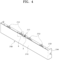
- FIG. 4 is a front perspective view of the cover panel constituting the control panel according to an embodiment of the present disclosure.
- the cover panel 2100 will now be described with reference to FIG. 4 .
- the upper surface portion 2120 of the cover panel 2100 may be provided with elements for coupling with other components.
- an electrical component module coupler 2121 may be formed in the center of the upper surface portion 2120.
- the electrical component module coupler 2121 may be a component configured to be coupled to the electrical component module 3000.
- a plurality of second front panel couplers 2123 may be formed at the upper surface portion 2120.
- the second front panel couplers 2123 may project in an outward direction of the cover panel 2100.
- the second front panel couplers 2123 may project in an upward direction of the cover panel 2100.
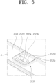
- FIG. 5 is a fragmentary enlarged view of region A in FIG. 4 .
- FIG. 6 is a plan view of the electrical component module coupler according to an embodiment of the present disclosure. The electrical component module coupler 2121 will now be described with reference to FIGs. 5 and 6 .
- the electrical component module coupler 2121 may be a component configured to couple the electrical component module 3000 to the cover panel 2100. In an embodiment, the electrical component module coupler 2121 may be coupled to the sealing cover 2300. The electrical component module coupler 2121 may be formed at a location corresponding to a cover panel coupling protrusion 2321 (see FIG. 20 ). The electrical component module coupler 2121 may be provided with a protrusion-receiving hole 2121a formed therein. In an embodiment, the protrusion-receiving hole 2121a may constitute the electrical component module coupler 2121. The protrusion-receiving hole 2121a may receive therein the cover panel coupling protrusion 2321 (see FIG. 20 ) formed at the sealing cover 2300.
- a slit 2121c may be formed around the protrusion-receiving hole 2121a.
- the term "slit” used herein may mean an opening having a narrow width.
- the slit 2121c may be formed so as to be blind at the rear side thereof and to surround the protrusion-receiving hole 2121a.
- the protrusion-receiving hole 2121a and the slit 2121c may be spaced apart from each other by a predetermined distance.
- the protrusion-receiving hole 2121a may be formed in an elastic surface 2121b which has elasticity higher than other portions of the upper surface portion 2120 by virtue of the slit 2121c.
- the slit 2121c may extend to a location which is spaced apart from the rear surface of the upper surface portion 2120.
- a reinforcing projection 2121e may be further formed along the outer periphery of the slit 2121c.
- a reinforcing projection 2121d may be further formed along the outer periphery of the protrusion-receiving hole 2121a.
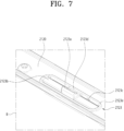
- FIG. 7 is a fragmentary enlarged view of portion B in FIG. 4 .
- FIG. 8 is a plan view of the second front panel coupler according to an embodiment of the present disclosure.
- the second front panel coupler 2123 will now be described with reference to FIGs 7 and 8 .
- the second front panel coupler 2123 is a component configured to be coupled to the second front panel 122 of the second treatment apparatus 20.
- the second front panel coupler 2123 may project in an outward direction of the cover panel 2100.
- the second front panel coupler 2123 may include a coupling protrusion 2123a.
- the coupling protrusion 2123a may be inserted into a groove or a hole formed in a lower portion of the second front panel 122.
- the coupling protrusion 2123a may have a triangular shape when viewed from a lateral side.
- the coupling protrusion 2123a may be inclined upwards as the same approaches the front end thereof from the rear end thereof.
- the height of the front end of the coupling protrusion 2123a may be higher than the rear end of the coupling protrusion 2123a.
- Slits 2123c which extend in rightward and leftward directions, may be formed before and behind the coupling protrusion 2123a. By virtue of the slits 2123c, an elastic surface 2123b has higher elasticity than other portions of the upper surface portion 2120.
- the coupling protrusion 2123a may be formed on the elastic surface 2123b.
- the outer peripheral portion of the coupling protrusion 2123a may project whereas the inner portion of the coupling protrusion 2123a may not project.
- the coupling protrusion 2123a may be provided with a recessed portion 2123f.
- the coupling protrusion 2123a may be connected to the upper surface portion 2120 across the slit 2123c via a bridge 2123d.
- a reinforcing projection 2123e may further be formed along the outer periphery of the slits 2123c.
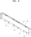
- FIG. 9 is a perspective view of the cover panel according to an embodiment of the present disclosure when viewed in a downward direction from the inside of the cover panel.
- the upper surface of the lower surface portion 2130 of the cover panel 2100 will now be described with reference to FIG. 9 .
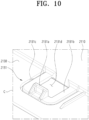
- FIG. 10 is a fragmentary enlarged view of portion C in FIG. 9 .
- the first restrainer 2131 will now be described with reference to FIG. 10 .
- the first restrainer 2131 may be a component configured to restrain the position of the electrical component module 3000.
- the first restrainer 2131 may include a first restraining protrusion 2131a.
- the first restraining protrusion 2131a may project inwards from the upper surface portion 2120 and/or the lower surface portion 2130 of the cover panel 2100.
- the first restraining protrusion 2131a may project inwards from the lower surface portion 2130.
- the first restraining protrusion 2131a may be formed at a location corresponding to a cover panel engaging protrusion 2337 (see FIG. 20 ).
- the first restraining protrusion 2131a may be positioned behind the cover panel engaging protrusion 2337.
- the first restraining protrusion 2131a may come into close contact with the cover panel engaging protrusion 2337 to restrain the sealing cover 2300 at the rear side of the sealing cover 2300.
- a slit 2131c may be formed around the first restraining protrusion 2131a.
- the slit 2131c may be formed so as to surround the first restraining protrusion 2131a.
- the width of the rear portion of the slit 2131c may be wider than the width of the first restraining protrusion 2131a.
- the slit 2131c may extend backwards from the front side of the upper surface portion 2120, and may extend along the rear side of the first restraining protrusion 2131a and then toward the front side of the upper surface portion 2120.
- the front ends of the slit 2131c may be closed.
- the slit 2131c may define an elastic surface 2131b.
- the first restraining protrusion 2131a may be formed on the elastic surface 2131b.
- the first restraining protrusion 2131a may be inclined upwards as the same approaches the front end from the rear end thereof.
- the height of the front end of the first restraining protrusion 2131a may be higher than the height of the rear end of the first restraining protrusion 2131a.
- the first restrainer 2131 may have an opening 2131d.
- the opening 2131d may have a length between the front end of the first restraining protrusion 2131a and the front side of the upper surface portion 2120, and a width wider than the first restraining protrusion 2131a.
- the opening 2131d may have a width sufficient to receive the cover panel engaging protrusion 2337.
- the cover panel engaging protrusion 2337 may be received in the opening 2131d.
- FIG. 11 is a fragmentary enlarged view of portion D in FIG. 9 .
- the second restrainer 2133 will now be described with reference to FIG. 11 .
- the second restrainer 2133 may be a component configured to restrain the position of the electrical component module 3000.
- the second restrainer 2133 may include a second restraining protrusion 2133a.
- the second restraining protrusion 2133a may project inwards from the upper surface portion 2120 and/or the lower surface portion 2130 of the cover panel 2100.
- the second restraining protrusion 2133a may project inwards (upwards) from the lower surface portion 2130.
- the second restraining protrusion 2133a may support the rear side of the supporter 2200, and may restrain the position of the supporter 2200.
- a first coupling groove 2232 see FIG.
- the second restraining protrusion 2133a may include a plurality of second restraining protrusions
- the first coupling groove 2232 may also include a plurality of first coupling grooves corresponding to the plurality of second restraining protrusions 2133a. At least one of the plurality of first coupling grooves 2232 may have the same width as the width of the second restraining protrusion 2133a.
- the term "same" may a concept meaning substantially identical including tolerance.
- the second restraining protrusion 2133a may be inserted into the first coupling groove 2232 so as to restrain the position of the supporter 2200.
- the second restraining protrusion 2133a may restrict movement of the supporter 2200 in forward and backward directions and in rightward and leftward directions.
- a slit 2133c may be formed around the second restraining protrusion 2133a.
- the slit 2133c may be formed so as to surround the second restraining protrusion 2133a.
- the width of the rear end of the slit 2133c may be identical to the width of the second restraining protrusion 2133a.
- the slit 2133c may extend backwards from a location, which is spaced apart from the front side of the upper surface portion 2120 by a predetermined distance, and may extend along the rear side of the second restraining protrusion 2133a to a location, which is spaced apart from the front side of the upper surface portion 2120 by a predetermined distance.
- the second restraining protrusion 2133a may be inclined upwards as the same approaches the front end from the rear end thereof.
- the height of the front end of the second restraining protrusion 2133a may be higher than the height of the rear end of the second restraining protrusion 2133a.
- the second restrainer 2133 may have an opening 2133d.
- the opening 2133d may have a length corresponding to the length that the slit 2133c extends from the front end of the second restraining protrusion 2133a, and a width similar to the width of the second restraining protrusion 2133a.
- FIG. 12 is a perspective view of the cover panel according to an embodiment of the present disclosure when viewed in an upward direction from the inside of the cover panel.
- the upper surface portion 2120 of the cover panel 2100 may be provided with a third restrainer 2125.
- the third restrainer 2125 may project downwards (inwards) from the upper surface portion 2120.
- the lower surface portion 2130 of the cover panel 2100 may be provided with a first front panel coupler 2135.
- the first front panel coupler 2135 may project in an outward direction of the cover panel 2100.
- the first front panel coupler 2135 may project in a downward direction of the cover panel 2100.
- FIG. 13 is a fragmentary enlarged view of portion E in FIG. 12 .
- the third restrainer 2125 may be a component configured to restrain the position of the electrical component module 3000.
- the third restrainer 2125 may include a third restraining protrusion 2125a.
- the third restraining protrusion 2125a may project inwards from the upper surface portion 2120 and/or the lower surface portion 2130 of the cover panel 2100.
- the third restraining protrusion 2125a may project inwards (downwards) from the lower surface portion 2130.
- the third restraining protrusion 2125a may support the rear side of the supporter 2200, and may restrain the position of the supporter 2200.
- the third restraining protrusion 2125a may have a rectangular shape when viewed from a lateral side.
- a second coupling groove 2222 (see FIG. 17 ) may be formed at a location of the supporter 2200 corresponding to the third restraining protrusion 2125a.
- the third restraining protrusion 2125a may include a plurality of third restraining protrusions, and the second coupling groove 2222 may also include a plurality of third coupling grooves, which correspond to the plurality of third restraining protrusions 2125a.
- At least one of the plurality of second coupling grooves 2222 may have the same width as the width of the third restraining protrusion 2125a.
- the third restraining protrusion 2125a may be inserted into the second coupling groove 2222 so as to restrain the position of the supporter 2200.
- the third restraining protrusion 2125a may restrain the position of the supporter 2200 in forward and backward directions and in rightward and leftward directions.
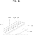
- FIG. 14 is a fragmentary enlarged view of portion F in FIG. 12 .
- FIG. 15 is a bottom view of the first front panel coupler according to an embodiment of the present disclosure. The first front panel coupler 2135 will now be described with reference to FIGs. 14 and 15 .
- Slits 2135c which extend in rightward and leftward directions, may be formed before and behind the coupling protrusion 2135a.
- an elastic surface 2135b which has elasticity higher than other portions of the lower surface portion 2130, may be formed.
- the coupling protrusion 2136a may be formed on the elastic surface 2135b.
- the outer peripheral portion of the coupling protrusion 2135a may project whereas the inner portion of the coupling protrusion 2135a may not project.
- the coupling protrusion 2135a may be provided with a recessed portion 2135f.
- a reinforcing projection 2135c may further be formed along the outer periphery of the slits 2135c.
- FIG. 16 is a front perspective view of the support constituting the control panel according to an embodiment of the present disclosure.
- FIG. 17 is a rear perspective view of the support constituting the control panel according to an embodiment of the present disclosure.
- FIG. 18 is a cross-sectional view taken along cross-sectional line I-I in FIG. 17 .
- the supporter 2200 according to an embodiment of the present disclosure will now be described with reference to FIGs. 16 to 18 .
- the supporter 2200 may include a supporter front surface portion 2210, a supporter upper surface portion 2220, and a supporter lower surface portion 2230.
- the supporter upper surface portion 2220 may be formed at the upper side of the supporter front surface portion 2210.
- the supporter upper surface portion 2220 may extend backwards from the upper end of the supporter front surface portion 2210.
- the supporter lower surface portion 2230 may be formed at the lower side of the supporter front surface portion 2210.
- the supporter lower surface portion 2230 may extend backwards from the lower end of the supporter front surface portion 2210.
- the supporter upper surface portion 2220 and the supporter lower surface portion 2230 include plurality of sealing cover couplers 2221 and 2231. Since the sealing cover couplers 2221 and 2231 project backwards from the supporter upper surface portion 2220 and the supporter lower surface portion 2230, it is possible to set the height of the control panel 2000 in an up-and-down direction to be low according to a desired design and to increase the height of the electrical component module 3000, which is advantageous in assurance of the surface area of the circuit board, the surface area of the flat display and the like.
- the supporter upper surface portion 2220 may be provided with the first sealing cover coupler 2221.
- the supporter upper portion 2230 may be provided with the second sealing cover coupler 2231.
- each of the sealing cover couplers 2221 and 2231 may be provided with a receiving hole.
- Each of the supporter couplers 2323 and 2333 may be embodied as a protrusion. The protrusions, which serve as the supporter couplers 2323 and 2333, may be received in the receiving holes in the sealing cover couplers 2221 and 2231 in order to couple the supporter 2200 and the sealing cover 2300 to each other.
- the receiving hole may be formed in the sealing cover coupler 2221.
- the receiving hole in the sealing cover coupler 2221 may receive the protrusion formed at the sealing cover 2300.
- the supporter front surface portion 2210 may be provided with a display seating portion 2211.
- the flat display 2400 may be positioned in the display seating portion 2211.
- the flat display 2400 may be seated in the display seating portion 2211.
- the display seating portion 2211 may be depressed backwards from the supporter front surface portion 2210.
- the depth by which the display seating portion 2211 is depressed may correspond to the thickness of the flat display 2400.
- a cable through hole 2211a may be formed through the display seating portion 2211 such that a cable for electrical connection between the flat display 2400 and the circuit board extends through the cable through hole 2211a.
- the cable through hole 2211a may be formed at the lower end of the display seating portion 2211.
- the supporter front surface portion 2210 may be provided with a speaker seating portion 2212.
- a speaker module may be disposed at the speaker seating portion 2212.
- a speaker hole 2212a may be formed through the speaker seating portion 2212 such that sound from the speaker is transmitted.
- the speaker seating portion 2212 may be formed at a location at which the speaker seating portion 2212 does not overlap the sealing cover 2300 when viewed from the front.
- the speaker seating portion 2212 may be formed the region outside the region defined by the first sealing groove 2219.
- a wireless communication module seating portion 2213 may be formed at the supporter front surface portion 2210.
- a wireless communication module may be disposed at the wireless communication module seating portion 2213.
- a communication hole 2213a may be formed in the wireless communication module seating portion 2213 to facilitate smooth wireless communication.
- the wireless communication may be implemented by Wi-Fi, Bluetooth or the like.
- the wireless communication module seating portion 2213 may be formed in the region outside the region defined by the first sealing groove 2219.
- a touch film through hole 2214 may be formed in the supporter front surface portion 2210 such that a touch film 2119 (see FIG. 24 ) passes through the touch film through hole 2214 to the rear side of the supporter 220 at which the circuit board is positioned.
- a second sealing groove 2218 may be formed in the supporter 2200.
- the second sealing groove 2218 may be formed at the rear side of the supporter 2200.
- the second sealing groove 2218 may be formed so as to surround a first region in which the circuit board for the flat display 2400 is disposed.
- the first region may be defined by a forward periphery which defines the first space 2390 to be described later.
- the second sealing groove 2218 may be formed at a location at which the second sealing groove 2218 faces the sealing projection 2320 (see FIG. 19 ) which is formed along the periphery of the sealing cover 2300 and projects forwards therefrom.
- the sealing projection 2320 may be inserted into the second sealing groove 2218.
- a second sealer 2810 may be inserted into the second sealing groove 2218.
- the sealing cover 2300 may be coupled to the supporter 2200 in the state in which the second sealer 2810 is inserted into the second sealing groove 2218.
- the sealing projection 2320 and the second sealer 2810 may be in close contact with each other.
- the sealing projection 2320 of the sealing cover 2300 may be inserted into the second sealing groove 2218.
- the second sealer 2810 may be pressed, thereby sealing the first space 2390 (see FIG. 21 ) which is the space defined by the supporter 2200 and the sealing cover 2300.
- the second sealer 2810 may be made of various materials, such as rubber, fluorine, silicone or the like.
- the first sealing groove 2219 may be formed in the supporter 2200.
- the first sealing groove 2219 may be formed at the front side of the supporter front surface portion 2210 of the supporter 2200.
- the first sealer 2820 may be inserted into the first sealing groove 2219.
- the first sealing groove 2219 may be formed in the region outside the display seating portion 2211 so as to surround the display seating portion 2211.
- the upper and lower portions of the first sealing groove 2219 may be formed so as to face the upper and lower portions of the second sealing groove 2218 with the supporter front surface portion 2210 interposed therebetween.
- the first sealer 2820 may be made of various materials, such as rubber, fluorine, silicone or the like.
- Intermediate grooves 2225 and 2235 may be formed between the second sealing groove 2218 and the first sealing groove 2219.
- the intermediate grooves 2225 and 2235 may include an upper intermediate groove 2225 and a lower intermediate groove 2235.
- the upper intermediate groove 2225 may be formed in the supporter upper surface portion 2220.
- the upper intermediate groove 2225 may be formed in a portion between the second sealing groove 2218 and the first sealing groove 2219 so as to open upwards.
- the outward direction of the supporter upper surface portion 2220 may be an upward direction.
- the lower intermediate groove 2235 may be formed in the supporter lower surface portion 2230.
- the lower intermediate groove 2235 may be formed in a portion between the second sealing groove 2218 and the first sealing groove 2219 so as to open downwards.
- the outward direction of the supporter lower surface portion 2230 may be a downward direction.
- the depth of the second sealing groove 2218 is decreased and thus the projecting length of the sealing projection 2320 is also decreased, it is possible to couple the supporter 2200 to the sealing cover 2300 using the protrusion and the groove, and it is possible to sufficiently press the second sealer 2810 to obtain sufficient sealing performance.
- the intermediate grooves 2225 and 2235 may be applied.
- the second sealing groove 2218 and the first sealing groove 2219 may face each other at portions thereof. In the portions of the second sealing groove 2218 and the first sealing groove 2219 that face each other, the distance between the second sealing groove 2218 and the first sealing groove 2219 may be greater than the distance between other portions of the second sealing groove 2218 and the first sealing groove 2219.
- the intermediate grooves 2225 and 2235 are provided, it is possible to space the second sealing groove 2218 and the first sealing groove 2219 apart from each other and to uniformly maintain the thickness throughout the supporter 2200.
- the second sealing groove 2218 and the first sealing groove 2219 may have the same width.
- the second sealer 2810 and the first sealer 2820 may have the same diameter.
- the second sealer 2810 and the first sealer 2820 may be made one and the same. Accordingly, the second sealer 2810 and the first sealer 2820 may be exchanged with each other, thereby improving convenience in a fabrication operation.
- the supporter lower surface portion 2230 may have one or more first coupling grooves 2232.
- the first coupling grooves 2232 may be embodied as grooves formed in the rear end of the supporter lower surface portion 2230.
- the first coupling grooves 2232 may include two first coupling grooves formed at two locations, and may be formed at locations near opposite ends of the supporter lower surface portion 2230.
- the first coupling grooves 2232 may be coupled to the second restrainers 2133.
- the second restraining protrusions 2133a of the second restrainers 2133 may be inserted into the first coupling grooves 2232.
- the width of at least one of the one or more first coupling holes 2232 may be equal to the width of a corresponding to the first coupling hole.
- the second restraining protrusions 2133a may be positioned behind the first coupling grooves 2232 so as to restrain forward and backward movement of the supporter 2200.
- the second constraining protrusions 2133a may be inserted into the first coupling grooves 2232 so as to restrain rightward and leftward movement of the supporter 2200. Because the second restraining protrusions 2133a are inserted into the first coupling grooves 2232, the position of the supporter 2200 with respect to the cover panel 2100 may be restrained. Furthermore, because the position of the supporter 2200 is restrained, the position of the electrical component module 3000 may be restrained.
- the supporter upper surface portion 2220 may be provided with one or more second coupling grooves 2222.
- the second coupling grooves 2222 may be embodied as grooves formed in the rear end of the supporter upper surface portion 2220. In an embodiment, the second coupling grooves 2222 may be formed at two locations near opposite ends of the supporter upper surface portion 2220.
- the second coupling grooves 2222 may be coupled to the third restrainers 2125.
- the third restraining protrusions 2125a of the third restrainers 2125 may be inserted into the second coupling grooves 2222.
- the width of at least one of the second coupling groove 2222 of the one or more second coupling grooves 2222 may be equal to the width of a corresponding third restraining protrusion 2125a.
- the third restraining protrusions 2125a may be positioned behind the second coupling grooves 2222 so as to restrain forward and backward movement of the supporter 2200.
- the third restraining protrusions 2125a may be inserted into the second coupling grooves 2222 so as to restrain rightward and leftward movement of the supporter 2200. Because the third restraining protrusions 2125a are inserted into the second coupling grooves 2222, the position of the supporter 2200 with respect to the cover panel 2100 may be restrained. Because the position of the supporter 2200 is restrained, the position of the electrical component module 3000 may be restrained.
- the third restrainer 2125 may be formed at the upper surface portion 2120 when the second restrainer 2133 is formed at the lower surface portion 2130 whereas the third restrainer 2125 may be formed at the lower surface portion 2130 when the second restrainer 2133 is formed at the upper surface portion.
- FIG. 19 is a rear perspective view of the sealing cover constituting the control panel according to an embodiment of the present disclosure.
- the sealing cover 2300 will now be described with reference to FIG. 19 .
- the sealing cover 2300 may include a sealing cover front surface portion 2310 and the sealing projection 2320.
- the sealing cover front surface portion 2310 may define the front surface of the sealing cover 2300.
- the sealing cover front surface portion 2310 may be formed so as to have a surface area smaller than the supporter front surface portion 2210.
- the speaker seating portion 2212 and the sealing cover front surface portion 2310 may be positioned so as not to overlap each other.
- the sealing cover front surface portion 2310 may be coupled to the supporter 220 at a portion thereof which does not overlap the speaker seating portion 2212.
- the wireless communication module seating portion 2213 and the sealing cover front surface portion 2310 may be positioned so as not to overlap each other.
- the sealing cover front surface portion 2310 may be coupled to the supporter 2200 at a portion thereof which does not overlap the wireless communication module seating portion 2213.
- the sealing projection 2320 may extend forwards along the periphery of the sealing cover front surface portion 2310.
- the sealing projection 2320 may be inserted into the second sealing groove 2218.
- the sealing projection 2320 may be formed to have a shape corresponding to the second sealing groove 2218.
- the sealing projection 2320 has been described as extending forwards along the periphery of the sealing cover front surface portion 2310, sealing projection 2320 may not extend along the periphery of the sealing cover front surface portion 2310 as long as the sealing projection 2320 has a shape corresponding to the second sealing groove 2218.
- the lower portion of the sealing projection 2320 may be provided with the second supporter coupler 2333.
- the first supporter coupler 2323 may be coupled to the second sealing cover coupler 2231 of the supporter 2200.
- the second supporter coupler 2333 may be formed to have the shape of a protrusion.
- the protrusion of the second supporter coupler 2333 may be received in the receiving hole in the second sealing cover coupler 2231.
- the supporter 2200 and the sealing cover 2300 may be fixed to each other in an up-and-down direction.
- the screw coupler 2330 may be coupled to the coupling boss 2215 by means of the screw element 900.
- the screw coupler 2330 may include two screw couplers disposed at the left side and two screw couplers disposed at the right side.
- the plurality of screw couplers 2330 may be spaced apart from each other by a predetermined distance.
- the sealing cover 2300 may include the cover panel coupler 2321.
- the cover panel coupler 2321 may be a component configured to couple the electrical component module 3000 to the cover panel 2100.
- the cover panel coupler 2321 may be embodied as a protrusion.
- the cover panel coupler 2321 may be provided as a cover panel coupling protrusion 2321.
- the sealing cover front surface portion 2310 may be provided with a wiring hole 2312.
- a cable (not shown) for transmission of power may access the circuit board 2500 and/or the flat display 2400 through the wiring hole 2312.
- a wiring hole projection 2313 may be formed around the wiring hole 2312.
- the wiring hole projection 2313 may extend in a backward direction of the wiring hole 2312.
- the wiring hole projection 2313 may be provided with a wiring hole sealer 2341.
- the wiring hole sealer 2314 may be inserted into the wiring hole projection 2313.
- the wiring hole sealer 2314 may seal the wiring hole 2312. Accordingly, by virtue of the wiring hole projection 2313, the wiring hole sealer 2314 may assure a length sufficient to obtain water-tightness and/or air-tightness.
- the wiring hole sealer 2314 may seal the remaining space other than the space through which the cable (not shown) extends.
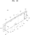
- FIG. 20 is a rear perspective view of the electrical component module according to an embodiment of the present disclosure.
- FIG. 21 is a cross-sectional view taken along cross-sectional line II-II in FIG. 20 .
- the coupling relationships between components constituting the electrical component module 3000 according to an embodiment of the present disclosure will now be described with reference to FIGs. 20 and 21 .
- the first sealing cover coupler 2221 of the supporter upper surface portion 2220 may be coupled to the first supporter coupler 2323 (see FIG. 19 ) of the sealing cover 2300.
- the second sealing cover coupler 2231 of the supporter upper surface portion 2220 may be coupled to the second supporter coupler 2333 (see FIG. 19 ) of the sealing cover 2300. Because the first sealing cover coupler 2221 and the second sealing cover coupler 2231 projects backwards from the supporter upper surface portion 2220 and the supporter lower surface portion 2230, respectively, it is possible to reduce the height of the electrical component module 3000.
- the screw coupler 2330 of the sealing cover 2300 may be coupled to the coupling boss 2215 (see FIG. 17 ) of the supporter 2200.
- the screw coupler 2430 and the coupling boss 2215 may be threadedly coupled to each other by means of the screw element 900. Because the screw coupler 2330 can be coupled to the coupling boss 2215 by applying torque using the screw element 900, it is also possible to increase coupling strength. Because the screw couplers 2330 are formed at the right and left sides of the sealing cover 2300, the second sealer 2810 may also be sufficiently pressed at the right side (2320b) and the left side (2320a) of the sealing projection 2320. Furthermore, because the screw coupling provides high coupling force, it is possible to improve coupling stability between the supporter 2200 and the sealing cover 2300.
- the upper end of the cover panel coupler 2321 may project outwards farther than the outer peripheral portion of the supporter 2200.
- the lower end of the cover panel engaging protrusion 2337 may project outwards farther than the outer peripheral portion of the supporter 2200.
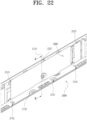
- FIG. 22 is an enlarged view of the coupling portion between the electrical component module and the cover panel according to an embodiment of the present disclosure when viewed from the rear in order to explain the coupling between the electrical component module and the cover panel.
- FIG. 23 is a cross-sectional view taken along cross-sectional line III-III in FIG. 24 .
- the coupling between the electrical component module 3000 and the cover panel 2100 according to an embodiment of the present disclosure will now be described with reference to FIGs. 22 and 23 .
- the first restrainer 2131 of the cover panel 2100 may press the cover panel engaging protrusion 2337 (see FIG. 20 ) from the rear to restrain the cover panel engaging protrusion 2337.
- the second restrainer 2133 of the cover panel 2100 may be coupled to the first coupling groove 2232 (see FIG. 17 ) of the supporter lower surface portion 2230.
- the third restrainer 2125 of the cover panel 2100 may be coupled to the first coupling groove 2232 (see FIG. 17 ) of the supporter upper surface portion 2220.
- the electrical component module coupler 2121 of the cover panel 2100 may be coupled to the cover panel coupling protrusion 2321 (see FIG. 20 ).
- the flat display 2400 may be positioned ahead of the supporter 2200.
- the touch film 2119 may be provided ahead of the flat display 2400.
- the touch film 2119 may be adhered to the rear surface of the cover panel 2100.
- the touch film 2119 may be electrically connected to the circuit board 2500.
- the laundry treatment apparatus 1 may receive user commands via the touch film 2119.
- the first sealer 2820 may be in close contact with the cover panel 2100.
- the space in which the flat display 2400 is seated may be isolated from the external space.
- water-tightness and air-tightness attributable to the first sealer 2820 may be improved.
- the flat display 2400 is vulnerable to humidity, there is a need to provide a sealing structure. According to an embodiment of the present disclosure, it is possible to obtain an appropriate sealing structure capable of protecting the first sealer 2820.
- the flat display 2400 may be isolated from the external space and thus be protected from humidity.
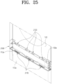
- FIG. 25 is a view illustrating the state in which the cover panel according to an embodiment of the present disclosure is coupled to the first front panel and the second front panel when viewed from the inner side.
- the coupling between the cover panel 2100 and the first front panel 112 and the second front panel 122 will now be described with reference to FIG. 25 .
- the lower surface portion 2130 of the cover panel 2100 may be coupled to an upper end bent portion 112a of the first front panel 112 of the first treatment apparatus 10.
- the cover panel 2100 and the first front panel 112 may be coupled to each other by inserting the first front panel coupler 2135 of the lower surface portion 2130 into the upper end bent portion 112a.
- FIG. 26 is a perspective view of the cover panel according to an embodiment of the present disclosure when viewed from the inner side.
- the cover panel according to an embodiment of the present disclosure will now be de additionally described with reference to FIG. 26 .
- the uniform zone 2115 may be formed to have a rectangular shape.
- the protrusions formed in the region which overlaps the uniform zone 2115 in an up-and-down direction do not overlap the uniform zone 2115 when viewed from the front (the front surface or the front side).
- the first restraining protrusion 2131a may overlap the uniform zone 2115 in an up-and-down direction.
- the height h1 that the first restraining protrusion 2131a projects may be less than the distance d1 between the lower surface of the uniform zone 2115 and the lower surface of the front surface portion 2110. Consequently, the uniform zone 2115 does not overlap the first restraining protrusion 2131a when viewed from the front.
Landscapes
- Engineering & Computer Science (AREA)
- Textile Engineering (AREA)
- Detail Structures Of Washing Machines And Dryers (AREA)
Abstract
Description
- The present disclosure relates to a laundry treatment apparatus.
- A laundry treatment apparatus is an apparatus designed to receive laundry such as clothes and bedclothes in a drum thereof and to perform a laundry treatment such as elimination of contaminants from the laundry or drying of the laundry.
- When a laundry treatment apparatus is designed to eliminate contaminants from laundry, the laundry treatment apparatus is capable of performing washing, rinsing, dewatering, spin-drying and the like. The laundry treatment apparatus may include a cabinet defining the appearance, a tub received in the cabinet, a drum rotatably mounted in the tub and receiving laundry therein, and a detergent supply unit configured to supply detergent to the inside of the drum. When the drum is rotated by a motor in the state in which washing water is supplied to the laundry received in the drum, contaminants may be eliminated from the laundry by virtue of frictional action between the laundry and the drum and the washing water.
- When a laundry treatment apparatus is designed to dry laundry, the laundry treatment apparatus is capable of removing moisture from laundry by supplying dry air to the laundry. The laundry treatment apparatus may include a cabinet, a drum rotatably provided in the cabinet, a heating unit configured to heat or dry air supplied to the laundry and the like. By supplying dry air to the laundry received in the drum, the moisture contained in the laundry may evaporate and be removed by the dry air, and water in the laundry may be removed.
-
Korea unexamined patent application publication No. 10-2008-0021921A1 related patent document 1 discloses the laundry treatment apparatus including a plurality of treatment apparatuses each of which includes the manipulation unit and the display unit. However, the laundry treatment apparatus is problematic in that a user must check the plurality of treatment apparatuses and respectively manipulate the plurality of treatment apparatuses and that it is disadvantageous to operate the plurality of treatment apparatuses in linkage with each other. -
Korea unexamined patent application publication No. 10-2021-0112087 - An object of the present disclosure is to provide a structure capable of improving workability in coupling between components constituting a control panel.
- An object of the present disclosure is to provide a laundry treatment apparatus capable of realizing a simple and clear design of a user interface (UI) by providing a control panel including a flat display and constructing the control panel using the flat display.
- An object of the present disclosure is to provide a structure capable of protecting a flat display, which is weak to humidity, from circumstances in which a laundry treatment apparatus is always exposed to humidity.
- An object of the present disclosure is to provide a coupling structure in which components constituting a control panel are stably coupled to each other so as to maintain sealing performance.
- An object of the present disclosure is to provide a laundry treatment apparatus capable of reducing quality deterioration of a screen which is transmitted to a user through a cover panel in construction of a control panel including a flat display.
- Objects, which are intended to be solved by the present disclosure, are not limited to the above-mentioned objects, and other objects of the present disclosure, which are not mentioned above, will be clearly understood by those skilled in the art from the following descriptions.
- The present disclosure provides a laundry treatment apparatus. In an embodiment, the laundry treatment apparatus includes a first treatment apparatus including a first front panel provided at a front side thereof and a first drum configured to receive laundry therein, a second treatment apparatus disposed on the first treatment apparatus, the second treatment apparatus including a second front panel provided at a front side thereof and a second drum configured to receive laundry therein, and a control panel provided between the first front panel and the second front panel and providing a user interface (UI) configured to control at least one of the first treatment apparatus or the second treatment apparatus, wherein the control panel includes a cover panel defining an appearance of the control panel, and an electrical component module coupled to a rear side of the cover panel, and wherein the electrical component module includes a flat display, a supporter including a display seating portion configured to support the flat display, and a first sealing portion which is provided on a front surface of the supporter so as to surround a region outside the display seating portion and at which a first sealer is positioned.
- According to an embodiment of the present disclosure, it is possible to obtain a structure capable of improving workability in coupling between components constituting a control panel.
- According to an embodiment of the present disclosure, it is possible to realize a simple and clear design of a user interface (UI) by providing a control panel including a flat display and constructing the control panel using the flat display.
- According to an embodiment of the present disclosure, it is possible to protect a flat display, which is weak to humidity, from circumstances in which a laundry treatment apparatus is always exposed to humidity.
- According to an embodiment of the present disclosure, it is possible to obtain a coupling structure in which components constituting a control panel are stably coupled to each other so as to maintain sealing performance.
- According to an embodiment of the present disclosure, it is possible to reduce quality deterioration of a screen which is transmitted to a user through a cover panel in construction of a control panel including a flat display.
- Effects of the present disclosure are not limited to the above-mentioned effects, and other effects of the present disclosure, which are not mentioned above, will be clearly understood by those skilled in the art to which the present disclosure belongs, from the following detailed description and the accompanying drawings.
-
-
FIG. 1 is a perspective view of a laundry treatment apparatus according to an embodiment of the present disclosure; -
FIG. 2 is a front perspective view of a control panel according to an embodiment of the present disclosure; -
FIG. 3 is an exploded perspective view of the control panel according to an embodiment of the present disclosure; -
FIG. 4 is a perspective view of a cover panel constituting the control panel according to an embodiment of the present disclosure; -
FIG. 5 is a fragmentary enlarged view of portion A inFIG. 4 ; -
FIG. 6 is a plan view of an electrical component module coupler according to an embodiment of the present disclosure; -
FIG. 7 is a fragmentary enlarged view of portion B inFIG. 4 ; -
FIG. 8 is a plan view of a second front panel coupler according to an embodiment of the present disclosure; -
FIG. 9 is a perspective view of the cover panel according to an embodiment of the present disclosure when viewed in a downward direction from the inside of the cover panel; -
FIG. 10 is a fragmentary enlarged view of portion C inFIG. 9 ; -
FIG. 11 is a fragmentary enlarged view of portion D inFIG. 9 ; -
FIG. 12 is a perspective view of the cover panel according to an embodiment of the present disclosure when viewed in an upward direction from the inside of the cover panel; -
FIG. 13 is a fragmentary enlarged view of portion E inFIG. 12 ; -
FIG. 14 is a fragmentary enlarged view of portion F inFIG. 12 ; -
FIG. 15 is a bottom view of a first front panel coupler according to an embodiment of the present disclosure; -
FIG. 16 is a front perspective view of a supporter constituting the control panel according to an embodiment of the present disclosure; -
FIG. 17 is a rear perspective view of the supporter constituting the control panel according to an embodiment of the present disclosure; -
FIG. 18 is a cross-sectional view taken along cross-sectional line I-I inFIG. 17 ; -
FIG. 19 is a rear perspective view of a sealing cover constituting the control panel according to an embodiment of the present disclosure; -
FIG. 20 is a rear perspective view of an electrical component module according to an embodiment of the present disclosure; -
FIG. 21 is a cross-sectional view taken along cross-sectional line II-II inFIG. 20 ; -
FIG. 22 is an enlarged view of the coupling portion between the electrical component module and the cover panel according to an embodiment of the present disclosure when viewed from the rear in order to explain coupling between the electrical component module and the cover panel; -
FIG. 23 is a cross-sectional view taken along cross-sectional line III-III inFIG. 24 ; -
FIG. 24 is a fragmentary enlarged view of portion G inFIG. 23 ; -
FIG. 25 is a view illustrating the state in which the cover panel according to an embodiment of the present disclosure is coupled to the first front panel and the second front panel when viewed from the inner side; and -
FIG. 26 is a perspective view of the cover panel according to an embodiment of the present disclosure when viewed from the inner side. - Hereinafter, with reference to the accompanying drawings, embodiments of the present disclosure will be described in detail so that those skilled in the art can easily implement the present disclosure.
- However, the present disclosure may be implemented in several different forms and is not limited to the embodiments described herein. In order to clearly illustrate the present disclosure, components not related to the description are omitted, and similar components are denoted by like reference numerals throughout the specification.
- In this specification, redundant descriptions of the same components are omitted.
- It will be understood that, when an element is referred to as being "connected" or "coupled" to another element, the element can be directly connected or coupled to the other element and an intervening element may also be present therebetween. In contrast, in this specification, it will be understood that, when an element is referred to as being "directly connected" or "directly coupled" to another element, there are no intervening elements present therebetween.
- The terminology used herein is merely for the purpose of describing particular embodiments, and is not intended to limit the scope of the present disclosure.
- In addition, as used herein, a singular form may encompass the plural form unless context dictates otherwise.
- In this specification, it will be further understood that the terms "comprise", "have", etc., specify the presence of stated features, integers, steps, operations, elements, components, or combinations thereof, but do not preclude the presence or addition of one or more other features, integers, steps, operations, elements, components, or combinations thereof.
- Furthermore, in this specification, the term "and/or" includes a combination of a plurality of related listed items or any of the plurality of related listed items. In this specification, "A or B" may include "A", "B", or "both A and B.".
-
FIG. 1 illustrates alaundry treatment apparatus 1 according to an embodiment of the present disclosure. According to an embodiment of the present disclosure, thelaundry treatment apparatus 1 includes afirst treatment apparatus 10, asecond treatment apparatus 20, and a control panel 200. - In the description of the present disclosure, forward direction (+X), a backward direction (-X), a first lateral direction (+Y), a second lateral direction (-Y), an upward direction (+Z), and a downward direction (-Z) of the components may be defined on the same basis. For example, the forward and backward directions (+X and -X) of the
first treatment apparatus 10 may be identically defined to the forward and backward directions of each of thesecond treatment apparatus 20 and the control panel 200, and the lateral direction (Y) and the upward and downward direction may also be defined in the same manner. - The
first treatment apparatus 10 and thesecond treatment apparatus 20 may be embodied as various kinds of apparatuses configured to treat laundry, such as a washing machine configured to wash laundry and/or a dryer configured to dry laundry. Thefirst treatment apparatus 10 may be a washing machine, and thesecond treatment apparatus 20 may be a dryer. Both thefirst treatment apparatus 10 and thesecond treatment apparatus 20 may be a washing machine or a dryer, or thefirst treatment apparatus 10 may be a dryer, and thesecond treatment apparatus 20 may be a washing machine. Each of thefirst treatment apparatus 10 and thesecond treatment apparatus 20 may be any of various kinds of apparatuses configured to treat laundry. - In an embodiment, the
first treatment apparatus 10, which is positioned at a lower level, may be embodied as a washing machine configured to wash laundry. Thefirst treatment apparatus 10 may be provided therein with afirst drum 12 and atub 14, which receive laundry therein. Thefirst drum 12 provided in thefirst treatment apparatus 10 may be rotatably provided in thetub 14. Thesecond treatment apparatus 20 may be positioned on thefirst treatment apparatus 10. Thefirst treatment apparatus 10 may support thesecond treatment apparatus 20. Thesecond treatment apparatus 20 may be embodied as a dryer configured to dry laundry. Thesecond treatment apparatus 20 may be provided with afirst drum 12 and atub 14. - The
first treatment apparatus 10 may include afirst cabinet 110 defining the appearance thereof. Thefirst cabinet 110 may be provided at the front side thereof with a firstfront panel 112. The firstfront panel 112 may include a laundry port communicating with thefirst drum 12. The laundry port may be opened and closed by afirst cabinet door 17. Thefirst drum 12 of thefirst treatment apparatus 10 according to an embodiment may have a rotational axis parallel to the forward and backward directions (+X and -Y). - The
first treatment apparatus 10 may be provided with a firstleft panel 115 in one lateral direction (+Y). Thefirst treatment apparatus 10 may be provided with a first right panel 116 (seeFIG. 2 ) in the opposite direction (-Y). Thefirst treatment apparatus 10 may be provided at the rear side thereof with a first rear panel (not shown). Thefirst treatment apparatus 10 may be provided at an upper side thereof with a first upper panel (not shown). Thefirst treatment apparatus 10 may be provided at the lower side thereof with a first lower panel (not shown). - The first
front panel 112, the firstlateral panel 115, the first rear panel (not shown), the first upper panel 119, and the first lower panel (not shown) may be combined with one another to form the first cabinet 100, and may be coupled to one another. Thefirst cabinet 110 may define therein a space in which inner components constituting thefirst treatment apparatus 10 are received. - The
first treatment apparatus 10 may be constructed such that laundry and the like to be treated is introduced into thefirst cabinet 110 through the laundry port so as to be received in thefirst drum 12, and may perform a treatment process. - The first
front panel 112 may be provided with a detergent opening into which adetergent storage unit 16 is inserted. In thelaundry treatment apparatus 1 according to an embodiment, thefirst treatment apparatus 10 may be installed on a floor, and thedetergent storage unit 16 may be positioned higher than the laundry port in thefirst treatment apparatus 10. Thedetergent storage unit 16 may be positioned between the laundry port in thefirst treatment apparatus 10 and the control panel 200. In other words, thedetergent storage unit 16 may be positioned higher than the laundry port in thefirst treatment apparatus 10 but lower than the control panel 200. Thedetergent storage unit 16 may be pushed into and pulled out of thefirst cabinet 110 by a user. For example, a user may separate thedetergent storage unit 16 from thefirst cabinet 110, may put detergent into thedetergent storage unit 16, and may push thedetergent storage unit 16 into thefirst cabinet 110. - In an embodiment, the first
front panel 112 may have a filter opening into which afilter unit 18 configured to collect foreign substances from washing water is inserted, and thefilter unit 18 is inserted into the filter opening. Thefilter unit 18 may be provided at one lateral side of a lower portion of the firstfront panel 112. Thefilter unit 18 may be introduced into thefirst cabinet 110 through the filter opening, and may be connected to a washing water path through which washing water is discharged from thetub 14. Thefilter unit 18 is capable of filtering foreign substances from the washing water discharged from thetub 14 after completion of a washing operation. The function of thefilter unit 18 is not necessarily limited to the filtering function for washing water. Thefilter unit 18 may be configured to filter foreign substances from various objects. For example, thefilter unit 18 may be configured to filter foreign substances from washing water required to perform a washing operation before initiation of the washing operation. - A user may push or pull the
filter unit 18 into or out of thefirst cabinet 110. Thefilter unit 18, which has been taken out of the first cabinet 100, may be washed and reused or may be replaced. Thefilter unit 18 may be put into and taken out of the filter opening with a higher frequency, compared to thedetergent storage unit 16. Accordingly, in an embodiment of the present disclosure, the detergent opening, into which thedetergent storage unit 16 which is put into and taken out of the detergent opening with a lower frequency is inserted, may be disposed at an upper side of the firstfront panel 112. In addition, the filter opening, into which thefilter unit 18 which is put into and taken out of the filter opening with a higher frequency is inserted, may be disposed at a lower side of the firstfront panel 112. Consequently, it is possible to realize the firstfront panel 112 which has excellent convenience in use and availability of a space. - Furthermore, the washing water discharge path, which is connected to the
tub 14 in thefirst cabinet 10, may be positioned at a lower side in thefirst cabinet 110 so as to allow easy discharge of washing water. In an embodiment of the present disclosure, thefilter unit 18 may be provided at the lower side of thefirst cabinet 110 so as to be efficiently connected to the washing water discharge path. - The
first treatment apparatus 10 may be provided with afirst apparatus controller 19. Thefirst apparatus controller 19 is a component configured to control various components constituting thefirst treatment apparatus 10. Thefirst apparatus controller 19 may be disposed in thefirst cabinet 110. Thefirst apparatus controller 19 may include a circuit board and electrical components mounted on the circuit board. In an embodiment, thefirst apparatus controller 19 may check information in a memory, corresponding to a manipulation signal received from the control panel 200, and may perform control corresponding to the manipulation signal. Thefirst apparatus controller 19 may transmit the state of thefirst treatment apparatus 10 to the control panel 200. - The
second treatment apparatus 20 may include asecond cabinet 120 defining the appearance thereof. Thesecond cabinet 120 may include a secondfront panel 122 provided at a front side thereof. The secondfront panel 122 may be provided with a laundry port communicating with thesecond drum 22. The laundry port may be opened and closed by asecond cabinet door 27. - The
second treatment apparatus 20 may be provided with a secondleft panel 125 in one lateral direction (+Y). Thesecond treatment apparatus 20 may be provided with a second right panel 126 (seeFIG. 2 ) in the opposite lateral direction (-Y). Thesecond treatment apparatus 20 may be provided at a rear side thereof with a second rear panel (not shown). Thesecond treatment apparatus 20 may be provided at an upper side thereof with a secondupper panel 127. Thesecond treatment apparatus 20 may be provided at a lower side thereof with a base (not shown). - The second
front panel 122, the secondlateral panel 125, the second rear panel (not shown), the secondupper panel 127, and the base 500 may be combined with one another to form thesecond cabinet 120, and may be coupled to one another. Thesecond cabinet 120 may define a space in which electrical components constituting thesecond treatment apparatus 20 are received together with thesecond drum 22. - Laundry and the like to be treated may be introduced into the
second cabinet 120 through the laundry port of thesecond treatment apparatus 20, and may then be received in thesecond drum 22. The laundry received in thesecond drum 22 may be subjected to treatment operations, such as washing, drying and the like, by thesecond treatment apparatus 20. - The
second treatment apparatus 20 according to an embodiment may be constructed such that the laundry port is provided at the secondfront panel 122 together with thesecond cabinet door 27. Thesecond drum 22 received in thesecond treatment apparatus 20 may have a rotational axis parallel to the forward and backward direction X. - The
second treatment apparatus 20 may be disposed on thefirst treatment apparatus 10. In an embodiment, the lower portion of thefirst treatment apparatus 10 may be coupled to the upper portion of thesecond treatment apparatus 20. The upper portion of thefirst treatment apparatus 10 may be constructed so as to support thesecond treatment apparatus 20. For example, the first upper panel (not shown) of thefirst treatment apparatus 10 may be constructed so as to directly and indirectly support the base 500 of thesecond treatment apparatus 20. - The
second treatment apparatus 20 may be provided with asecond apparatus controller 29. Thesecond apparatus controller 29 is a component configured to control various components constituting thesecond treatment apparatus 20. Thesecond apparatus controller 29 may be disposed in thesecond cabinet 120. Thesecond apparatus controller 29 may include a circuit board and electrical components mounted on the circuit board. In an embodiment, thesecond apparatus controller 29 may check information in a memory, corresponding to a manipulation signal received from the control panel 200, and may perform control corresponding to the manipulation signal. Thesecond apparatus controller 29 may transmit the state of thesecond treatment apparatus 20 to the control panel 200. - The control panel 200 may be disposed between the first
front panel 112 and the secondfront panel 122. Since the control panel 200 is provided between the firstfront panel 112 and the secondfront panel 122 at a level almost corresponding to a user's waist, it is possible to assure a height convenient to manipulate the control panel. The control panel 200 may be connected to at least one of thefirst treatment apparatus 10 or thesecond treatment apparatus 20 in a signal communication manner. In an embodiment, the control panel 200 may be connected to thefirst treatment apparatus 10 and the second treatment apparatus 200 in a signal communication manner. In an embodiment, the control panel 200 may be connected to thefirst apparatus controller 19 and/or thesecond treatment apparatus 20 in a signal communication manner. A user interface (UI) may be displayed on the front surface of the control panel 200. A user may control thefirst treatment apparatus 10 and/or thesecond treatment apparatus 20 through the control panel 200. - The
laundry treatment apparatus 1 may be provided at the rear side thereof with arear bracket 300. Therear bracket 300 may be coupled both to thefirst treatment apparatus 10 and to thesecond treatment apparatus 20. Therear bracket 300 may be disposed at an upper portion of a rear side of thefirst treatment apparatus 10 and at a lower portion of a rear side of thesecond treatment apparatus 20. Therear bracket 300 may be provided with a handle for a transporting person. A transporting person may easily move thelaundry treatment apparatus 1 using the handle formed at therear bracket 300. -
FIG. 2 is a front perspective view of the control panel according to an embodiment of the present disclosure. The control panel will now be described with reference toFIG. 2 . - The
control panel 2000 may include acover panel 2100. An electrical component module 3000 (seeFIG. 3 ) may be positioned at the rear side of thecover panel 2100. Thecover panel 2100 may include afront surface portion 2110, anupper surface portion 2120, a lower surface portion 2130 (seeFIG. 9 ), a firstlateral surface portion 2142, and a secondlateral surface portion 2144. Thefront surface portion 2110 may define the appearance of thecover panel 2100. Theupper surface portion 2120 may extend backwards from the upper surface of thefront surface portion 2110. The firstlateral surface portion 2142 may extend backwards from a first lateral surface of thefront surface portion 2110. The secondlateral surface portion 2144 may extend backwards from a second lateral surface of thefront surface portion 2110. -
FIG. 3 is an exploded perspective view of the control panel according to an embodiment of the present disclosure. - The
control panel 2000 may include thecover panel 2100 and theelectrical component module 3000. Theelectrical component module 3000 may be disposed behind thecover panel 2100 and coupled to thecover panel 2100. Theelectrical component module 3000 may include asupporter 2200, a sealingcover 2300, aflat display 2400, and acircuit board 2500. - The
supporter 2200 is a component configured to support theflat display 2400. Thesupporter 2200 may have a panel-shaped front surface. Thesupporter 2200 may be coupled both to theupper surface portion 2120 and to thelower surface portion 2130 of thecover panel 2100. - The
flat display 2400 may be positioned on the front surface of thesupporter 2200. Theflat display 2400 may be supported by thesupporter 2200. Theflat display 2400 may be positioned between thecover panel 2100 and thesupporter 2200. In the description of the present disclosure, theflat display 2400 may refer to a thin display, and may be provided as any of various forms such as LCDs, PDPs, AMLCLs, PMLCDs, OLEDs and LEDs. - The sealing
cover 2300 may be positioned behind thesupporter 2200, and may be coupled to thesupporter 2200. The sealingcover 2300 may cover thecircuit board 2500. The sealingcover 2300 may be positioned behind thecircuit board 2500. Thecircuit board 2500 may be positioned in the first space 2390 (seeFIG. 21 ) defined between the sealingcover 2300 and thesupporter 2200. - The
circuit board 2500 may include a plurality of circuit boards. Some of thecircuit boards 2500 may be covered by thecover panel 2100 so as to be prevented from contacting external air. Thecircuit boards 2500 may include a circuit board for a speaker to be described later, acircuit board 2510 for theflat display 2400 and atouch button 2511 functioning as an input button, and a circuit board for a communication module. The circuit board for theflat display 2400 may be electrically connected to theflat display 2400 so as to transmit a signal to theflat display 2400. Furthermore, the circuit board for theflat display 2400 may receive an input signal of a user through the user interface. In an embodiment, the circuit board for theflat display 2400 may be covered by the sealingcover 2300 so as to be prevented from contacting external air. - The
circuit board 2510 for theflat display 2400 may be provided with thetouch button 2511. Thetouch button 2511 may be composed of a pair of components, that is, a light-emitting member and a touch sensor. The light-emitting member may display whether or not the corresponding touch sensor is activated. For example, when the touch sensor is activated, the light-emitting member may emit light. The light-emitting device may be embodied as an LED. Thesupporter 2200 may concentrate the light diffused from the light-emitting device on a certain location. In an embodiment, thesupporter 2200 may include at least onesensor hole 2216 formed therein. The sensor hole 2116 may be formed at a location corresponding to the location of thetouch button 2511. The sensor hole 2116 may form a blocking wall which extends from the periphery of the hole forwards or backwards. The blocking wall may prevent the light emitted from the light-emitting device from diffusing around thetouch button 2511. Since thecircuit board 2510 is positioned behind thesupporter 2200, it is possible to prevent diffusion of the light of thetouch button 2511. -
FIG. 4 is a front perspective view of the cover panel constituting the control panel according to an embodiment of the present disclosure. Thecover panel 2100 will now be described with reference toFIG. 4 . - The
upper surface portion 2120 of thecover panel 2100 may be provided with elements for coupling with other components. In an embodiment, an electricalcomponent module coupler 2121 may be formed in the center of theupper surface portion 2120. The electricalcomponent module coupler 2121 may be a component configured to be coupled to theelectrical component module 3000. In an embodiment, a plurality of secondfront panel couplers 2123 may be formed at theupper surface portion 2120. The secondfront panel couplers 2123 may project in an outward direction of thecover panel 2100. The secondfront panel couplers 2123 may project in an upward direction of thecover panel 2100. -
FIG. 5 is a fragmentary enlarged view of region A inFIG. 4 .FIG. 6 is a plan view of the electrical component module coupler according to an embodiment of the present disclosure. The electricalcomponent module coupler 2121 will now be described with reference toFIGs. 5 and6 . - The electrical
component module coupler 2121 may be a component configured to couple theelectrical component module 3000 to thecover panel 2100. In an embodiment, the electricalcomponent module coupler 2121 may be coupled to the sealingcover 2300. The electricalcomponent module coupler 2121 may be formed at a location corresponding to a cover panel coupling protrusion 2321 (seeFIG. 20 ). The electricalcomponent module coupler 2121 may be provided with a protrusion-receivinghole 2121a formed therein. In an embodiment, the protrusion-receivinghole 2121a may constitute the electricalcomponent module coupler 2121. The protrusion-receivinghole 2121a may receive therein the cover panel coupling protrusion 2321 (seeFIG. 20 ) formed at the sealingcover 2300. - In an embodiment, a
slit 2121c may be formed around the protrusion-receivinghole 2121a. The term "slit" used herein may mean an opening having a narrow width. Theslit 2121c may be formed so as to be blind at the rear side thereof and to surround the protrusion-receivinghole 2121a. The protrusion-receivinghole 2121a and theslit 2121c may be spaced apart from each other by a predetermined distance. The protrusion-receivinghole 2121a may be formed in anelastic surface 2121b which has elasticity higher than other portions of theupper surface portion 2120 by virtue of theslit 2121c. Theslit 2121c may extend to a location which is spaced apart from the rear surface of theupper surface portion 2120. - A reinforcing
projection 2121e may be further formed along the outer periphery of theslit 2121c. A reinforcingprojection 2121d may be further formed along the outer periphery of the protrusion-receivinghole 2121a. -
FIG. 7 is a fragmentary enlarged view of portion B inFIG. 4 .FIG. 8 is a plan view of the second front panel coupler according to an embodiment of the present disclosure. The secondfront panel coupler 2123 will now be described with reference toFIGs 7 and8 . The secondfront panel coupler 2123 is a component configured to be coupled to the secondfront panel 122 of thesecond treatment apparatus 20. The secondfront panel coupler 2123 may project in an outward direction of thecover panel 2100. The secondfront panel coupler 2123 may include acoupling protrusion 2123a. Thecoupling protrusion 2123a may be inserted into a groove or a hole formed in a lower portion of the secondfront panel 122. Thecoupling protrusion 2123a may have a triangular shape when viewed from a lateral side. Thecoupling protrusion 2123a may be inclined upwards as the same approaches the front end thereof from the rear end thereof. The height of the front end of thecoupling protrusion 2123a may be higher than the rear end of thecoupling protrusion 2123a.Slits 2123c, which extend in rightward and leftward directions, may be formed before and behind thecoupling protrusion 2123a. By virtue of theslits 2123c, anelastic surface 2123b has higher elasticity than other portions of theupper surface portion 2120. Thecoupling protrusion 2123a may be formed on theelastic surface 2123b. The outer peripheral portion of thecoupling protrusion 2123a may project whereas the inner portion of thecoupling protrusion 2123a may not project. In an embodiment, thecoupling protrusion 2123a may be provided with a recessedportion 2123f. Thecoupling protrusion 2123a may be connected to theupper surface portion 2120 across theslit 2123c via abridge 2123d. A reinforcingprojection 2123e may further be formed along the outer periphery of theslits 2123c. -
FIG. 9 is a perspective view of the cover panel according to an embodiment of the present disclosure when viewed in a downward direction from the inside of the cover panel. The upper surface of thelower surface portion 2130 of thecover panel 2100 will now be described with reference toFIG. 9 . - The
lower surface portion 2130 of thecover panel 2100 may include afirst restrainer 2131 and asecond restrainer 2133. Thefirst restrainer 2131 may project upwards (inwards) from thelower surface portion 2130. Thefirst restrainer 2131 may be formed on the inside of thesecond restrainer 2133, and may include a plurality of first restrainers. The plurality offirst restrainers 2131 may be symmetrically formed in the center of thecover panel 2100. Thesecond restrainer 2133 may project upwards (inwards) from thelower surface portion 2130 of thesecond restrainer 2133. Thesecond restrainer 2133 may be formed on the outer side of thefirst restrainer 2131, and may include a plurality of second restrainers. The plurality ofsecond restrainers 2133 may be symmetrically formed in the center of thecover panel 2100. -
FIG. 10 is a fragmentary enlarged view of portion C inFIG. 9 . Thefirst restrainer 2131 will now be described with reference toFIG. 10 . - The
first restrainer 2131 may be a component configured to restrain the position of theelectrical component module 3000. In an embodiment, thefirst restrainer 2131 may include afirst restraining protrusion 2131a. Thefirst restraining protrusion 2131a may project inwards from theupper surface portion 2120 and/or thelower surface portion 2130 of thecover panel 2100. Thefirst restraining protrusion 2131a may project inwards from thelower surface portion 2130. Thefirst restraining protrusion 2131a may be formed at a location corresponding to a cover panel engaging protrusion 2337 (seeFIG. 20 ). Thefirst restraining protrusion 2131a may be positioned behind the coverpanel engaging protrusion 2337. Thefirst restraining protrusion 2131a may come into close contact with the coverpanel engaging protrusion 2337 to restrain the sealingcover 2300 at the rear side of the sealingcover 2300. - A
slit 2131c may be formed around thefirst restraining protrusion 2131a. Theslit 2131c may be formed so as to surround thefirst restraining protrusion 2131a. The width of the rear portion of theslit 2131c may be wider than the width of thefirst restraining protrusion 2131a. Theslit 2131c may extend backwards from the front side of theupper surface portion 2120, and may extend along the rear side of thefirst restraining protrusion 2131a and then toward the front side of theupper surface portion 2120. The front ends of theslit 2131c may be closed. Theslit 2131c may define anelastic surface 2131b. Thefirst restraining protrusion 2131a may be formed on theelastic surface 2131b. Thefirst restraining protrusion 2131a may be inclined upwards as the same approaches the front end from the rear end thereof. The height of the front end of thefirst restraining protrusion 2131a may be higher than the height of the rear end of thefirst restraining protrusion 2131a. - The
first restrainer 2131 may have anopening 2131d. Theopening 2131d may have a length between the front end of thefirst restraining protrusion 2131a and the front side of theupper surface portion 2120, and a width wider than thefirst restraining protrusion 2131a. Theopening 2131d may have a width sufficient to receive the coverpanel engaging protrusion 2337. The coverpanel engaging protrusion 2337 may be received in theopening 2131d. -
FIG. 11 is a fragmentary enlarged view of portion D inFIG. 9 . Thesecond restrainer 2133 will now be described with reference toFIG. 11 . - The
second restrainer 2133 may be a component configured to restrain the position of theelectrical component module 3000. In an embodiment, thesecond restrainer 2133 may include asecond restraining protrusion 2133a. Thesecond restraining protrusion 2133a may project inwards from theupper surface portion 2120 and/or thelower surface portion 2130 of thecover panel 2100. In an embodiment, thesecond restraining protrusion 2133a may project inwards (upwards) from thelower surface portion 2130. Thesecond restraining protrusion 2133a may support the rear side of thesupporter 2200, and may restrain the position of thesupporter 2200. A first coupling groove 2232 (seeFIG. 17 ) may be formed at a location of thesupporter 2200 corresponding to thesecond restraining protrusion 2133a. Thesecond restraining protrusion 2133a may include a plurality of second restraining protrusions, and thefirst coupling groove 2232 may also include a plurality of first coupling grooves corresponding to the plurality ofsecond restraining protrusions 2133a. At least one of the plurality offirst coupling grooves 2232 may have the same width as the width of thesecond restraining protrusion 2133a. Here, the term "same" may a concept meaning substantially identical including tolerance. Thesecond restraining protrusion 2133a may be inserted into thefirst coupling groove 2232 so as to restrain the position of thesupporter 2200. Thesecond restraining protrusion 2133a may restrict movement of thesupporter 2200 in forward and backward directions and in rightward and leftward directions. - A
slit 2133c may be formed around thesecond restraining protrusion 2133a. Theslit 2133c may be formed so as to surround thesecond restraining protrusion 2133a. The width of the rear end of theslit 2133c may be identical to the width of thesecond restraining protrusion 2133a. Theslit 2133c may extend backwards from a location, which is spaced apart from the front side of theupper surface portion 2120 by a predetermined distance, and may extend along the rear side of thesecond restraining protrusion 2133a to a location, which is spaced apart from the front side of theupper surface portion 2120 by a predetermined distance. Thesecond restraining protrusion 2133a may be inclined upwards as the same approaches the front end from the rear end thereof. The height of the front end of thesecond restraining protrusion 2133a may be higher than the height of the rear end of thesecond restraining protrusion 2133a. - The
second restrainer 2133 may have anopening 2133d. Theopening 2133d may have a length corresponding to the length that theslit 2133c extends from the front end of thesecond restraining protrusion 2133a, and a width similar to the width of thesecond restraining protrusion 2133a. - Both the
second restrainer 2133 and the electricalcomponent module coupler 2121 may be formed at one of theupper surface portion 2120 and thelower surface portion 2130. In an embodiment, thesecond restrainer 2133 and the electricalcomponent module coupler 2121 may be formed at theupper surface portion 2120. -
FIG. 12 is a perspective view of the cover panel according to an embodiment of the present disclosure when viewed in an upward direction from the inside of the cover panel. - The
upper surface portion 2120 of thecover panel 2100 may be provided with athird restrainer 2125. Thethird restrainer 2125 may project downwards (inwards) from theupper surface portion 2120. In an embodiment, thelower surface portion 2130 of thecover panel 2100 may be provided with a firstfront panel coupler 2135. The firstfront panel coupler 2135 may project in an outward direction of thecover panel 2100. The firstfront panel coupler 2135 may project in a downward direction of thecover panel 2100. -
FIG. 13 is a fragmentary enlarged view of portion E inFIG. 12 . - The
third restrainer 2125 may be a component configured to restrain the position of theelectrical component module 3000. In an embodiment, thethird restrainer 2125 may include athird restraining protrusion 2125a. Thethird restraining protrusion 2125a may project inwards from theupper surface portion 2120 and/or thelower surface portion 2130 of thecover panel 2100. In an embodiment, thethird restraining protrusion 2125a may project inwards (downwards) from thelower surface portion 2130. Thethird restraining protrusion 2125a may support the rear side of thesupporter 2200, and may restrain the position of thesupporter 2200. In an embodiment, thethird restraining protrusion 2125a may have a rectangular shape when viewed from a lateral side. A second coupling groove 2222 (seeFIG. 17 ) may be formed at a location of thesupporter 2200 corresponding to thethird restraining protrusion 2125a. Thethird restraining protrusion 2125a may include a plurality of third restraining protrusions, and thesecond coupling groove 2222 may also include a plurality of third coupling grooves, which correspond to the plurality ofthird restraining protrusions 2125a. At least one of the plurality ofsecond coupling grooves 2222 may have the same width as the width of thethird restraining protrusion 2125a. Here, the term "same" may be a concept meaning substantially identical including a tolerance. Thethird restraining protrusion 2125a may be inserted into thesecond coupling groove 2222 so as to restrain the position of thesupporter 2200. Thethird restraining protrusion 2125a may restrain the position of thesupporter 2200 in forward and backward directions and in rightward and leftward directions. -
FIG. 14 is a fragmentary enlarged view of portion F inFIG. 12 .FIG. 15 is a bottom view of the first front panel coupler according to an embodiment of the present disclosure. The firstfront panel coupler 2135 will now be described with reference toFIGs. 14 and15 . - The first
front panel coupler 2135 may be a component to be coupled to the firstfront panel 112 of thefirst treatment apparatus 10. The firstfront panel coupler 2135 may project in an outward direction of thecover panel 2100. The firstfront panel coupler 2135 may include acoupling protrusion 2135a. Thecoupling protrusion 2135a may be inserted into a groove or a hole formed in the upper portion of the firstfront panel 112. Thecoupling protrusion 2135 may be inclined upwards as the same approaches the rear end from the front end thereof. The height of the rear end of thecoupling protrusion 2135a may be higher than the height of the front end of thecoupling protrusion 2135a.Slits 2135c, which extend in rightward and leftward directions, may be formed before and behind thecoupling protrusion 2135a. By virtue of theslits 2135c, anelastic surface 2135b, which has elasticity higher than other portions of thelower surface portion 2130, may be formed. The coupling protrusion 2136a may be formed on theelastic surface 2135b. The outer peripheral portion of thecoupling protrusion 2135a may project whereas the inner portion of thecoupling protrusion 2135a may not project. In an embodiment, thecoupling protrusion 2135a may be provided with a recessedportion 2135f. A reinforcingprojection 2135c may further be formed along the outer periphery of theslits 2135c. -
FIG. 16 is a front perspective view of the support constituting the control panel according to an embodiment of the present disclosure.FIG. 17 is a rear perspective view of the support constituting the control panel according to an embodiment of the present disclosure.FIG. 18 is a cross-sectional view taken along cross-sectional line I-I inFIG. 17 . Thesupporter 2200 according to an embodiment of the present disclosure will now be described with reference toFIGs. 16 to 18 . - The
supporter 2200 may include a supporterfront surface portion 2210, a supporterupper surface portion 2220, and a supporterlower surface portion 2230. The supporterupper surface portion 2220 may be formed at the upper side of the supporterfront surface portion 2210. The supporterupper surface portion 2220 may extend backwards from the upper end of the supporterfront surface portion 2210. The supporterlower surface portion 2230 may be formed at the lower side of the supporterfront surface portion 2210. The supporterlower surface portion 2230 may extend backwards from the lower end of the supporterfront surface portion 2210. - The supporter
upper surface portion 2220 and the supporterlower surface portion 2230 include plurality of sealingcover couplers cover couplers upper surface portion 2220 and the supporterlower surface portion 2230, it is possible to set the height of thecontrol panel 2000 in an up-and-down direction to be low according to a desired design and to increase the height of theelectrical component module 3000, which is advantageous in assurance of the surface area of the circuit board, the surface area of the flat display and the like. In an embodiment, the supporterupper surface portion 2220 may be provided with the firstsealing cover coupler 2221. The supporterupper portion 2230 may be provided with the secondsealing cover coupler 2231. The firstsealing cover coupler 2221 may include two first sealing cover couplers. The plurality of firstsealing cover couplers 2221 may be formed at locations, which are spaced apart from each other by a determined distance. The secondsealing cover coupler 2231 may include three second sealing cover couplers. The plurality of secondsealing cover couplers 2231 may be formed at locations, which are spaced apart from one another by a determined distance. The firstsealing cover coupler 2221 may be coupled to a first supporter coupler 2323 (seeFIG. 19 ) formed at the sealingcover 2300. The secondsealing cover coupler 2231 may be coupled to a second supporter coupler 2333 (seeFIG. 19 ) formed at the sealingcover 2300. In an embodiment, each of the sealingcover couplers supporter couplers supporter couplers cover couplers supporter 2200 and the sealingcover 2300 to each other. - The receiving hole may be formed in the sealing
cover coupler 2221. The receiving hole in the sealingcover coupler 2221 may receive the protrusion formed at the sealingcover 2300. - The supporter
front surface portion 2210 may be provided with adisplay seating portion 2211. Theflat display 2400 may be positioned in thedisplay seating portion 2211. Theflat display 2400 may be seated in thedisplay seating portion 2211. Thedisplay seating portion 2211 may be depressed backwards from the supporterfront surface portion 2210. The depth by which thedisplay seating portion 2211 is depressed may correspond to the thickness of theflat display 2400. A cable throughhole 2211a may be formed through thedisplay seating portion 2211 such that a cable for electrical connection between theflat display 2400 and the circuit board extends through the cable throughhole 2211a. The cable throughhole 2211a may be formed at the lower end of thedisplay seating portion 2211. - A
first sealing groove 2219 may be formed in the region of the supporterfront surface portion 2210 outside thedisplay seating portion 2211. A first sealer 2820 (seeFIG. 24 ) may be inserted into the sealinggroove 2219. - The supporter
front surface portion 2210 may be provided with aspeaker seating portion 2212. A speaker module may be disposed at thespeaker seating portion 2212. Aspeaker hole 2212a may be formed through thespeaker seating portion 2212 such that sound from the speaker is transmitted. Thespeaker seating portion 2212 may be formed at a location at which thespeaker seating portion 2212 does not overlap the sealingcover 2300 when viewed from the front. Thespeaker seating portion 2212 may be formed the region outside the region defined by thefirst sealing groove 2219. - A wireless communication
module seating portion 2213 may be formed at the supporterfront surface portion 2210. A wireless communication module may be disposed at the wireless communicationmodule seating portion 2213. Acommunication hole 2213a may be formed in the wireless communicationmodule seating portion 2213 to facilitate smooth wireless communication. The wireless communication may be implemented by Wi-Fi, Bluetooth or the like. The wireless communicationmodule seating portion 2213 may be formed in the region outside the region defined by thefirst sealing groove 2219. - A touch film through
hole 2214 may be formed in the supporterfront surface portion 2210 such that a touch film 2119 (seeFIG. 24 ) passes through the touch film throughhole 2214 to the rear side of the supporter 220 at which the circuit board is positioned. - A
second sealing groove 2218 may be formed in thesupporter 2200. Thesecond sealing groove 2218 may be formed at the rear side of thesupporter 2200. Thesecond sealing groove 2218 may be formed so as to surround a first region in which the circuit board for theflat display 2400 is disposed. The first region may be defined by a forward periphery which defines thefirst space 2390 to be described later. Thesecond sealing groove 2218 may be formed at a location at which thesecond sealing groove 2218 faces the sealing projection 2320 (seeFIG. 19 ) which is formed along the periphery of the sealingcover 2300 and projects forwards therefrom. The sealingprojection 2320 may be inserted into thesecond sealing groove 2218. Asecond sealer 2810 may be inserted into thesecond sealing groove 2218. The sealingcover 2300 may be coupled to thesupporter 2200 in the state in which thesecond sealer 2810 is inserted into thesecond sealing groove 2218. By coupling thesupporter 2200 to the sealingcover 2300, the sealingprojection 2320 and thesecond sealer 2810 may be in close contact with each other. For coupling with thesupporter 2200, the sealingprojection 2320 of the sealingcover 2300 may be inserted into thesecond sealing groove 2218. At this time, thesecond sealer 2810 may be pressed, thereby sealing the first space 2390 (seeFIG. 21 ) which is the space defined by thesupporter 2200 and the sealingcover 2300. Thesecond sealer 2810 may be made of various materials, such as rubber, fluorine, silicone or the like. - The
first sealing groove 2219 may be formed in thesupporter 2200. Thefirst sealing groove 2219 may be formed at the front side of the supporterfront surface portion 2210 of thesupporter 2200. Thefirst sealer 2820 may be inserted into thefirst sealing groove 2219. Thefirst sealing groove 2219 may be formed in the region outside thedisplay seating portion 2211 so as to surround thedisplay seating portion 2211. The upper and lower portions of thefirst sealing groove 2219 may be formed so as to face the upper and lower portions of thesecond sealing groove 2218 with the supporterfront surface portion 2210 interposed therebetween. Thefirst sealer 2820 may be made of various materials, such as rubber, fluorine, silicone or the like. -
Intermediate grooves second sealing groove 2218 and thefirst sealing groove 2219. Theintermediate grooves intermediate groove 2225 and a lowerintermediate groove 2235. The upperintermediate groove 2225 may be formed in the supporterupper surface portion 2220. The upperintermediate groove 2225 may be formed in a portion between thesecond sealing groove 2218 and thefirst sealing groove 2219 so as to open upwards. The outward direction of the supporterupper surface portion 2220 may be an upward direction. The lowerintermediate groove 2235 may be formed in the supporterlower surface portion 2230. The lowerintermediate groove 2235 may be formed in a portion between thesecond sealing groove 2218 and thefirst sealing groove 2219 so as to open downwards. The outward direction of the supporterlower surface portion 2230 may be a downward direction. - According to an embodiment of the present disclosure, setting of the depth of the
second sealing groove 2218 is limited. When the depth of thesecond sealing groove 2218 is increased, it is possible to sufficiently press thesecond sealer 2810 only when the length of the sealingprojection 2320 is increased. However, when the length of the sealingprojection 2320 is increased, it is difficult to perform smooth coupling using a protrusion. Therefore, setting of the depth of thesecond sealing groove 2218 is limited. Because the bottom surface of thesecond sealing groove 2218, which defines the depth of thesecond sealing groove 2218, is positioned at the rear side, it is possible to reduce the length of the sealingprojection 2320 of the sealingcover 2300. According to an embodiment of the present disclosure, because the depth of thesecond sealing groove 2218 is decreased and thus the projecting length of the sealingprojection 2320 is also decreased, it is possible to couple thesupporter 2200 to the sealingcover 2300 using the protrusion and the groove, and it is possible to sufficiently press thesecond sealer 2810 to obtain sufficient sealing performance. To this end, theintermediate grooves - In an embodiment, the
second sealing groove 2218 and thefirst sealing groove 2219 may face each other at portions thereof. In the portions of thesecond sealing groove 2218 and thefirst sealing groove 2219 that face each other, the distance between thesecond sealing groove 2218 and thefirst sealing groove 2219 may be greater than the distance between other portions of thesecond sealing groove 2218 and thefirst sealing groove 2219. In injection molding of components, there is a need to maintain an appropriate thickness. For example, if one portion is formed to have a thickness greater than another portion, there may be problem in that the thicker portion may warp or break during cooling after injection molding. According to an embodiment of the present disclosure, because theintermediate grooves second sealing groove 2218 and thefirst sealing groove 2219 apart from each other and to uniformly maintain the thickness throughout thesupporter 2200. - The
second sealing groove 2218 and thefirst sealing groove 2219 may have the same width. Thesecond sealer 2810 and thefirst sealer 2820 may have the same diameter. In an embodiment, thesecond sealer 2810 and thefirst sealer 2820 may be made one and the same. Accordingly, thesecond sealer 2810 and thefirst sealer 2820 may be exchanged with each other, thereby improving convenience in a fabrication operation. - The supporter 220 may be provided at the rear side thereof with
coupling bosses 2215. Thecoupling bosses 2215 may be formed at location corresponding to screw couplers 2330 (seeFIG. 19 ) of the sealingcover 2300. Thecoupling bosses 2215 may be formed in the region outside thesecond sealing groove 2218. In an embodiment, thescrew coupler 2330 of the sealingcover 2300 may project in rightward and leftward directions of the sealingprojection 2320. Thecoupling bosses 2215 may be coupled to thescrew couplers 2330 via screw elements 900 (seeFIG. 20 ). Because thecoupling bosses 2215 and thescrew couplers 2330 are coupled to each other by means of thefastening member 900, thesupporter 2200 and the sealingcover 2300 may be coupled to each other with higher coupling force. When the supporter 220 and the sealingcover 2300 are strongly coupled to each other, water-tightness and/or air-tightness attributable to thesecond sealer 2810 may be improved. - The supporter
lower surface portion 2230 may have one or morefirst coupling grooves 2232. Thefirst coupling grooves 2232 may be embodied as grooves formed in the rear end of the supporterlower surface portion 2230. In an embodiment, thefirst coupling grooves 2232 may include two first coupling grooves formed at two locations, and may be formed at locations near opposite ends of the supporterlower surface portion 2230. Thefirst coupling grooves 2232 may be coupled to thesecond restrainers 2133. Thesecond restraining protrusions 2133a of thesecond restrainers 2133 may be inserted into thefirst coupling grooves 2232. The width of at least one of the one or morefirst coupling holes 2232 may be equal to the width of a corresponding to the first coupling hole. Here, the term "equal" may be a concept including a tolerance. Thesecond restraining protrusions 2133a may be positioned behind thefirst coupling grooves 2232 so as to restrain forward and backward movement of thesupporter 2200. The second constrainingprotrusions 2133a may be inserted into thefirst coupling grooves 2232 so as to restrain rightward and leftward movement of thesupporter 2200. Because thesecond restraining protrusions 2133a are inserted into thefirst coupling grooves 2232, the position of thesupporter 2200 with respect to thecover panel 2100 may be restrained. Furthermore, because the position of thesupporter 2200 is restrained, the position of theelectrical component module 3000 may be restrained. - The supporter
upper surface portion 2220 may be provided with one or moresecond coupling grooves 2222. Thesecond coupling grooves 2222 may be embodied as grooves formed in the rear end of the supporterupper surface portion 2220. In an embodiment, thesecond coupling grooves 2222 may be formed at two locations near opposite ends of the supporterupper surface portion 2220. Thesecond coupling grooves 2222 may be coupled to thethird restrainers 2125. Thethird restraining protrusions 2125a of thethird restrainers 2125 may be inserted into thesecond coupling grooves 2222. The width of at least one of thesecond coupling groove 2222 of the one or moresecond coupling grooves 2222 may be equal to the width of a correspondingthird restraining protrusion 2125a. Here, the term "equal" may be a concept including tolerance. Thethird restraining protrusions 2125a may be positioned behind thesecond coupling grooves 2222 so as to restrain forward and backward movement of thesupporter 2200. Thethird restraining protrusions 2125a may be inserted into thesecond coupling grooves 2222 so as to restrain rightward and leftward movement of thesupporter 2200. Because thethird restraining protrusions 2125a are inserted into thesecond coupling grooves 2222, the position of thesupporter 2200 with respect to thecover panel 2100 may be restrained. Because the position of thesupporter 2200 is restrained, the position of theelectrical component module 3000 may be restrained. - In an embodiment, the
third restrainer 2125 may be formed at theupper surface portion 2120 when thesecond restrainer 2133 is formed at thelower surface portion 2130 whereas thethird restrainer 2125 may be formed at thelower surface portion 2130 when thesecond restrainer 2133 is formed at the upper surface portion. By virtue of thesecond restrainer 2133 and thethird restrainer 2125, the position of thesupporter 2200 in an up-and-down direction may be restrained, thereby making it possible to couple thecover panel 2100 to theelectrical component module 3000. -
FIG. 19 is a rear perspective view of the sealing cover constituting the control panel according to an embodiment of the present disclosure. The sealingcover 2300 will now be described with reference toFIG. 19 . - The sealing
cover 2300 may include a sealing coverfront surface portion 2310 and the sealingprojection 2320. - The sealing cover
front surface portion 2310 may define the front surface of the sealingcover 2300. In an embodiment, the sealing coverfront surface portion 2310 may be formed so as to have a surface area smaller than the supporterfront surface portion 2210. Thespeaker seating portion 2212 and the sealing coverfront surface portion 2310 may be positioned so as not to overlap each other. The sealing coverfront surface portion 2310 may be coupled to the supporter 220 at a portion thereof which does not overlap thespeaker seating portion 2212. The wireless communicationmodule seating portion 2213 and the sealing coverfront surface portion 2310 may be positioned so as not to overlap each other. The sealing coverfront surface portion 2310 may be coupled to thesupporter 2200 at a portion thereof which does not overlap the wireless communicationmodule seating portion 2213. - The sealing
projection 2320 may extend forwards along the periphery of the sealing coverfront surface portion 2310. The sealingprojection 2320 may be inserted into thesecond sealing groove 2218. The sealingprojection 2320 may be formed to have a shape corresponding to thesecond sealing groove 2218. Although the sealingprojection 2320 has been described as extending forwards along the periphery of the sealing coverfront surface portion 2310, sealingprojection 2320 may not extend along the periphery of the sealing coverfront surface portion 2310 as long as the sealingprojection 2320 has a shape corresponding to thesecond sealing groove 2218. - The upper portion of the sealing
projection 2320 may be provided with thefirst supporter coupler 2323. Thefirst supporter coupler 2323 may be coupled to the sealingcover coupler 2221 of thesupporter 2200. Thefirst supporter coupler 2323 may be formed to have the shape of a protrusion. The protrusion of thefirst supporter coupler 2323 may be received in the receiving hole in the firstsealing cover coupler 2221. By virtue of the coupling of thefirst supporter coupler 2323 with the firstsealing cover coupler 2221, thesupporter 2200 and the sealingcover 2300 may be coupled to each other. The coupling of thefirst supporter coupler 2323 with the firstsealing cover coupler 2221 may be performed at a location at which thesealing cover 2300 can sufficiently press thesecond sealer 2810. - The lower portion of the sealing
projection 2320 may be provided with thesecond supporter coupler 2333. Thefirst supporter coupler 2323 may be coupled to the secondsealing cover coupler 2231 of thesupporter 2200. Thesecond supporter coupler 2333 may be formed to have the shape of a protrusion. The protrusion of thesecond supporter coupler 2333 may be received in the receiving hole in the secondsealing cover coupler 2231. By virtue of the coupling of thesecond supporter coupler 2333 with the secondsealing cover coupler 2231, thesupporter 2200 and the sealingcover 2300 may be coupled to each other. The coupling of thesecond supporter coupler 2333 with the secondsealing cover coupler 2231 may be performed at a location at which thesealing cover 2300 can sufficiently press thefirst sealer 2820. - Because the
first supporter coupler 2323 and the firstsealing cover coupler 2221 are coupled to each other at an upper side and thesecond supporter coupler 2333 and the secondsealing cover coupler 2231 are coupled to each other at a lower side, thesupporter 2200 and the sealingcover 2300 may be fixed to each other in an up-and-down direction. - In an embodiment, the coupling stability between the
supporter 2200 and the sealingcover 2300 may be low only by the coupling of thesupporter couplers cover couplers projection 2320 may be provided with thescrew coupler 2330. Thescrew coupler 2330 may project from the sealingprojection 2320. In an embodiment, thescrew coupler 2330 may include a protrusion projecting from the sealingprojection 2320 and a screw through hole formed through the protrusion. The rear side of thesupporter 2200 may be provided with thecoupling boss 2215 at a location corresponding to thescrew coupler 2330. Thescrew coupler 2330 may be coupled to thecoupling boss 2215 by means of thescrew element 900. In an embodiment, thescrew coupler 2330 may include two screw couplers disposed at the left side and two screw couplers disposed at the right side. When a plurality ofscrew couplers 2330 are formed at each side, the plurality ofscrew couplers 2330 may be spaced apart from each other by a predetermined distance. By virtue of the screw coupling of thescrew coupler 2330 with thecoupling boss 2215, it is possible to improve the coupling stability between thesupporter 2200 and the sealingcover 2300. Because thescrew coupler 2330 can be coupled to thecoupling boss 2215 by applying torque using thescrew element 900, it is also possible to increase the coupling strength. Because thescrew couplers 2330 are formed at the right and left sides of sealingcover 2300, thesecond sealer 2810 can also be sufficiently pressed at theleft side 2320a and theright side 2320b of the sealingprojection 2320. - The sealing
cover 2300 may include thecover panel coupler 2321. Thecover panel coupler 2321 may be a component configured to couple theelectrical component module 3000 to thecover panel 2100. Thecover panel coupler 2321 may be embodied as a protrusion. In an embodiment, thecover panel coupler 2321 may be provided as a coverpanel coupling protrusion 2321. - The cover
panel coupling protrusion 2321 may project from one of the upper portion and the lower portion of the sealingcover 2300. In an embodiment, the coverpanel coupling protrusion 2321 may project from the center of the upper portion of the sealingcover 2300. The protrusion-receivinghole 2121a of the electricalcomponent module coupler 2121 may be formed at a location corresponding to the coverpanel coupling protrusion 2321. When the coverpanel coupling protrusion 2321 is inserted into and received in the protrusion-receivinghole 2121a and thus coupled thereto, the position of theelectrical component module 3000 with respect to thecover panel 2100 may be restrained. When the coverpanel coupling protrusion 2321 is inserted into and received in the protrusion-receivinghole 2121a and thus coupled thereto, theelectrical component module 3000 may be coupled to thecover panel 2100. - The sealing
cover 2300 may include the coverpanel engaging protrusion 2337. The coverpanel engaging protrusion 2337 may be a component configured to push and restrain theelectrical component module 3000 in a direction of thefront surface portion 2110 of thecover panel 2100. The coverpanel engaging protrusion 2337 may be pressed forwards by thefirst restraining protrusion 2131 of thecover panel 2100. Thefirst restraining protrusion 2131a of thefirst restrainer 2131 may be positioned behind the coverpanel engaging protrusion 2337, and may elastically press the coverpanel engaging protrusion 2337. The elasticity of the first restraining protrusion may be created by theslit 2131c. In an embodiment, the coverpanel engaging protrusion 2337 may be inserted into theopening 2131d in thefirst restrainer 2131, and may be pressed by thefirst restraining protrusion 2131a. - The sealing cover
front surface portion 2310 may be provided with awiring hole 2312. A cable (not shown) for transmission of power may access thecircuit board 2500 and/or theflat display 2400 through thewiring hole 2312. Awiring hole projection 2313 may be formed around thewiring hole 2312. Thewiring hole projection 2313 may extend in a backward direction of thewiring hole 2312. Thewiring hole projection 2313 may be provided with a wiring hole sealer 2341. Thewiring hole sealer 2314 may be inserted into thewiring hole projection 2313. Thewiring hole sealer 2314 may seal thewiring hole 2312. Accordingly, by virtue of thewiring hole projection 2313, thewiring hole sealer 2314 may assure a length sufficient to obtain water-tightness and/or air-tightness. Thewiring hole sealer 2314 may seal the remaining space other than the space through which the cable (not shown) extends. -
FIG. 20 is a rear perspective view of the electrical component module according to an embodiment of the present disclosure.FIG. 21 is a cross-sectional view taken along cross-sectional line II-II inFIG. 20 . The coupling relationships between components constituting theelectrical component module 3000 according to an embodiment of the present disclosure will now be described with reference toFIGs. 20 and21 . - The first
sealing cover coupler 2221 of the supporterupper surface portion 2220 may be coupled to the first supporter coupler 2323 (seeFIG. 19 ) of the sealingcover 2300. The secondsealing cover coupler 2231 of the supporterupper surface portion 2220 may be coupled to the second supporter coupler 2333 (seeFIG. 19 ) of the sealingcover 2300. Because the firstsealing cover coupler 2221 and the secondsealing cover coupler 2231 projects backwards from the supporterupper surface portion 2220 and the supporterlower surface portion 2230, respectively, it is possible to reduce the height of theelectrical component module 3000. - The
screw coupler 2330 of the sealingcover 2300 may be coupled to the coupling boss 2215 (seeFIG. 17 ) of thesupporter 2200. The screw coupler 2430 and thecoupling boss 2215 may be threadedly coupled to each other by means of thescrew element 900. Because thescrew coupler 2330 can be coupled to thecoupling boss 2215 by applying torque using thescrew element 900, it is also possible to increase coupling strength. Because thescrew couplers 2330 are formed at the right and left sides of the sealingcover 2300, thesecond sealer 2810 may also be sufficiently pressed at the right side (2320b) and the left side (2320a) of the sealingprojection 2320. Furthermore, because the screw coupling provides high coupling force, it is possible to improve coupling stability between thesupporter 2200 and the sealingcover 2300. - The sealing
projection 2320 may come into contact with thesecond sealer 2810 disposed in thesecond sealing groove 2218 and may press thesecond sealer 2810. In an embodiment, the sealingprojection 2320 may be inserted into thesecond sealing groove 2218. Because the sealingprojection 2320 presses thesecond sealer 2810, thefirst space 2390 may be isolated from the external space. In an embodiment of the present disclosure, theflat display 2400 may be provided. Because theflat display 2400 is vulnerable to humidity, a sealing structure is needed. According to an embodiment of the present disclosure, it is possible to obtain an appropriate sealing structure capable of protecting theflat display 2400. Because thefist space 2390 is isolated from the external space, it is possible to protect theflat display 2400 and thecircuit board 2500 for theflat display 2400 from humidity. - The upper end of the
cover panel coupler 2321 may project outwards farther than the outer peripheral portion of thesupporter 2200. The lower end of the coverpanel engaging protrusion 2337 may project outwards farther than the outer peripheral portion of thesupporter 2200. -
FIG. 22 is an enlarged view of the coupling portion between the electrical component module and the cover panel according to an embodiment of the present disclosure when viewed from the rear in order to explain the coupling between the electrical component module and the cover panel.FIG. 23 is a cross-sectional view taken along cross-sectional line III-III inFIG. 24 . The coupling between theelectrical component module 3000 and thecover panel 2100 according to an embodiment of the present disclosure will now be described with reference toFIGs. 22 and23 . - The first restrainer 2131 of the
cover panel 2100 may press the cover panel engaging protrusion 2337 (seeFIG. 20 ) from the rear to restrain the coverpanel engaging protrusion 2337. Thesecond restrainer 2133 of thecover panel 2100 may be coupled to the first coupling groove 2232 (seeFIG. 17 ) of the supporterlower surface portion 2230. The third restrainer 2125 of thecover panel 2100 may be coupled to the first coupling groove 2232 (seeFIG. 17 ) of the supporterupper surface portion 2220. The electricalcomponent module coupler 2121 of thecover panel 2100 may be coupled to the cover panel coupling protrusion 2321 (seeFIG. 20 ). - The
flat display 2400 may be positioned ahead of thesupporter 2200. Thetouch film 2119 may be provided ahead of theflat display 2400. Thetouch film 2119 may be adhered to the rear surface of thecover panel 2100. Thetouch film 2119 may be electrically connected to thecircuit board 2500. Thelaundry treatment apparatus 1 may receive user commands via thetouch film 2119. - The
electrical component module 3000 may be coupled to the rear side of thecover panel 2100. In an embodiment, theelectrical component module 3000 may be received in the space defined by thefront surface portion 2110, theupper surface portion 2120, thelower surface portion 2130, the firstlateral surface portion 2142 and the secondlateral surface portion 2144 of thecover panel 2100. - By virtue of the coupling between the
cover panel 2100 and thesupporter 2200, thefirst sealer 2820 may be in close contact with thecover panel 2100. By virtue of the close contact between thefirst sealer 2820 and thecover panel 2100, the space in which theflat display 2400 is seated may be isolated from the external space. When thesupporter 2200 and thecover panel 2100 are strongly coupled to each other, water-tightness and air-tightness attributable to thefirst sealer 2820 may be improved. Because theflat display 2400 is vulnerable to humidity, there is a need to provide a sealing structure. According to an embodiment of the present disclosure, it is possible to obtain an appropriate sealing structure capable of protecting thefirst sealer 2820. By virtue of thefirst sealer 2820, theflat display 2400 may be isolated from the external space and thus be protected from humidity. -
FIG. 24 is a fragmentary enlarged view of portion G inFIG. 23 . The sealing structure according to an embodiment of the present disclosure will now be described with reference toFIG. 24 . - The
second sealer 2810 may be inserted into thesecond sealing groove 2218, and may exert sealing performance by being pressed by the sealingprojection 2320. Thefirst sealer 2820 may be inserted into thefirst sealing groove 2219 so as to come into contact with thefront surface portion 2110, and may exert sealing performance by the pressing force with theelectrical component module 3000 is coupled to thecover panel 2100. -
FIG. 25 is a view illustrating the state in which the cover panel according to an embodiment of the present disclosure is coupled to the first front panel and the second front panel when viewed from the inner side. The coupling between thecover panel 2100 and the firstfront panel 112 and the secondfront panel 122 will now be described with reference toFIG. 25 . - In an embodiment, the
control panel 2000 may be coupled to the firstfront panel 112 and the secondfront panel 122 via thecover panel 2100. - The
lower surface portion 2130 of thecover panel 2100 may be coupled to an upper endbent portion 112a of the firstfront panel 112 of thefirst treatment apparatus 10. Thecover panel 2100 and the firstfront panel 112 may be coupled to each other by inserting the firstfront panel coupler 2135 of thelower surface portion 2130 into the upper endbent portion 112a. - The
upper surface portion 2120 of thecover panel 2100 may be coupled to a lower endbent portion 122a of the secondfront panel 122 of thesecond treatment apparatus 20. Thecover panel 2100 may be coupled to the secondfront panel 122 by inserting the secondfront panel coupler 2123 into a coupling hole (not shown) in the lower endbent portion 122a. -
FIG. 26 is a perspective view of the cover panel according to an embodiment of the present disclosure when viewed from the inner side. The cover panel according to an embodiment of the present disclosure will now be de additionally described with reference toFIG. 26 . - The
control panel 2000 according to an embodiment of the present disclosure may include theflat display 2400. When the region of thefront surface portion 2110 in which theflat display 2400 is provided does not have a uniform thickness, the quality of the screen which is transmitted through thecover panel 2100 is not good. For example, fine projections are formed in the region in which theflat display 2400 is provided due to various causes occurring in a manufacturing process, the quality of the screen which is transmitted through thecover panel 2100 may be deteriorated. - In an embodiment of the present disclosure, the
cover panel 2100 may include auniform zone 2115. The inner region of theuniform zone 2115 may be formed by a surface having no projecting portion. The flat surface which constitutes theuniform zone 2115 may form a uniform surface. Theuniform zone 2115 may be larger than the region which is occupied by the screen of theflat display 2400. Theflat display 2400 may be positioned in the region in which theflat display 2400 overlaps theuniform zone 2115. When viewed from the front, theportion 2117 to which theflat display 2400 is projected may be positioned in theuniform zone 2115. - In an embodiment, the
uniform zone 2115 may be formed to have a rectangular shape. In an embodiment, the protrusions formed in the region which overlaps theuniform zone 2115 in an up-and-down direction do not overlap theuniform zone 2115 when viewed from the front (the front surface or the front side). In an embodiment, thefirst restraining protrusion 2131a may overlap theuniform zone 2115 in an up-and-down direction. The height h1 that thefirst restraining protrusion 2131a projects may be less than the distance d1 between the lower surface of theuniform zone 2115 and the lower surface of thefront surface portion 2110. Consequently, theuniform zone 2115 does not overlap thefirst restraining protrusion 2131a when viewed from the front. - Although the present disclosure has been illustrated and described with reference to the specific embodiments, those skilled in the art will appreciate that various modifications, additions and substitutions are possible, without departing from the scope and spirit of the present disclosure as disclosed in the accompanying claims.
Claims (21)
- A laundry treatment apparatus comprising:a first treatment apparatus comprising a first front panel provided at a front side thereof and a first drum configured to receive laundry therein;a second treatment apparatus disposed on the first treatment apparatus, the second treatment apparatus comprising a second front panel provided at a front side thereof and a second drum configured to receive laundry therein; anda control panel positioned between the first front panel and the second front panel, providing a user interface (UI) configured to control at least one of the first treatment apparatus or the second treatment apparatus,wherein the control panel comprises:a cover panel defining an exteriorof the control panel; andan electrical component module coupled to a rear side of the cover panel, andwherein the electrical component module comprises:a flat display;a supporter comprising a display seating portion configured to supporter the flat display; anda first sealing portion which is provided on a front surface of the supporter so as to surround a region outside the display seating portion and at which a first sealer is positioned.
- The laundry treatment apparatus of claim 1, wherein the supporter is configured to be coupled to the cover panel such that the first sealer comes into contact with the cover panel.
- The laundry treatment apparatus of claim 1, wherein the first sealing portion comprises a first sealing groove into which the first sealer is inserted.
- The laundry treatment apparatus of claim 1, further comprising:a circuit board positioned behind the supporter and electrically connected to the flat display; anda sealing cover positioned behind the circuit board so as to cover the circuit board and coupled to the supporter.
- The laundry treatment apparatus of claim 4, wherein a rear surface of the supporter is provided with a second sealing portion surroundinga region outside the circuit board and in which a second sealer is positioned,
wherein the sealing cover comprises:a front surface portion; anda sealing projection extending from a portion of the front surface portion that faces the second sealer, andwherein the sealing cover is coupled to the supporter such that the sealing projection comes into contact with the second sealer. - The laundry treatment apparatus of claim 5, wherein the second sealing portion comprises a second sealing groove in which the second sealer is inserted.
- The laundry treatment apparatus of claim 5, wherein the first sealing portion comprises a first sealing groove in which the first sealer is inserted,wherein the second sealing portion comprises a second sealing groove into which the second sealer is inserted, andwherein upper and lower ends of the first sealing groove are configured to be positioned so as to face upper and lower ends of the second sealing groove.
- The laundry treatment apparatus of claim 7, wherein the supporter comprises:a supporter front surface portion comprising the display seating portion;a supporter upper surface portion formed at an upper side of the supporter front surface portion; anda supporter lower surface portion formed at a lower side of the supporter front surface portion,wherein, in the supporter upper surface portion and the supporter lower surface portion, an intermediate groove is configured to be formed between the second sealing groove and the first sealing groove so as to open in an outward direction.
- A laundry treatment apparatus comprising:a first treatment apparatus comprising a first front panel provided at a front side thereof and a first drum configured to receive laundry therein;a second treatment apparatus positioned above the first treatment apparatus, the second treatment apparatus comprising a second front panel provided at a front side thereof and a second drum configured to receive laundry therein; anda control panel positioned between the first front panel and the second front panel and providing a user interface (UI) configured to control at least one of the first treatment apparatus or the second treatment apparatus,wherein the control panel comprises:a cover panel defining the exteriorof the control panel; andan electrical component module coupled to a rear side of the cover panel, andwherein the electrical component module comprises:a flat display;a supporter comprising a display seating portion configured to supporter the flat display;a circuit board positioned behind the supporter and electrically connected to the flat display; anda sealing cover positioned behind the circuit board so as to cover the circuit board and coupled to the supporter.
- The laundry treatment apparatus of claim 9, wherein a rear surface of the supporter is provided with a second sealing portion which surrounds a region outside the circuit board and at which a second sealer is positioned.
- The laundry treatment apparatus of claim 10, wherein the sealing cover comprises:a front surface portion; anda sealing projection extendingfrom a portion of the front surface portion that faces the second sealer, andwherein the sealing cover is coupled to the supporter such that the sealing projection comes into contact with the second sealer.
- The laundry treatment apparatus of claim 11, wherein the second sealing portion comprises a second sealing groove in which the second sealer is inserted.
- The laundry treatment apparatus of claim 4 or 9, wherein the supporter comprises:a supporter front surface portion defining an appearance of the supporter;a supporter upper surface portion formed at an upper side of the supporter front surface portion; anda supporter lower surface portion formed at a lower side of the supporter front surface portion,wherein each of the supporter upper surface portion and the supporter lower surface portion comprises a sealing cover coupler which projects backwards, andwherein a sealing cover comprises a supporter coupler which is formed at a location corresponding to the sealing cover coupler of the supporter and which is inserted into the sealing cover coupler and coupled thereto.
- The laundry treatment apparatus of claim 4 or 9, wherein the sealing cover further comprises screw couplers formed at right and left sides thereof,wherein the supporter further comprises a coupling boss formed at a location corresponding to the screw coupler, andwherein the screw coupler and the coupling boss are configured to be coupled to each other via a screw element.
- The laundry treatment apparatus of claim 4 or 9, wherein the sealing cover comprises a wiring hole,wherein a cable configured to transmit power to the circuit board is provided to the circuit board through the wiring hole, andwherein the wiring hole is provided with a wiring hole sealer configured to seal the wiring hole.
- The laundry treatment apparatus of claim 15, wherein the sealing cover comprises a wiring hole projection which projects backwards along a periphery of the wiring hole.
- The laundry treatment apparatus of claim 4 or 9, wherein the sealing cover comprises a cover panel engaging protrusion which projects toward an upper surface portion or a lower surface portion of the cover panel.
- The laundry treatment apparatus of claim 17, wherein the cover panel comprises a first restraining protrusion which projects inwards from the upper surface portion or the lower surface portion of the cover panel and which is positioned behind the cover panel engaging protrusion so as to restrain the sealing cover.
- The laundry treatment apparatus of claim 18, wherein the cover panel further comprises a second restraining protrusion, which projects in an inward direction of the cover panel so as to be positioned behind the supporter and which is inserted into a groove formed in the supporter to restrain a position of the supporter.
- The laundry treatment apparatus of claim 18, wherein the cover panel further comprises a third restraining protrusion which projects in an inward direction from the cover panel so as to be positioned behind the supporter and to constrain a position of the supporter.
- The laundry treatment apparatus of claim 4 or 9, wherein the sealing cover further comprises a cover panel coupler which projects from one of upper and lower portions thereof,wherein the cover panel further comprises an electrical component module coupler which is formed at a location corresponding to the cover panel coupler, andwherein one of the cover panel coupler and the electrical component module coupler is configured to be received in a protrusion-receiving hole formed in another of the cover panel coupler and the electrical component module coupler and coupled thereto.
Applications Claiming Priority (2)
| Application Number | Priority Date | Filing Date | Title |
|---|---|---|---|
| KR1020220073531A KR102895270B1 (en) | 2022-06-16 | 2022-06-16 | Apparatus for treating laundry |
| PCT/KR2023/008295 WO2023244039A1 (en) | 2022-06-16 | 2023-06-15 | Apparatus for treating laundry |
Publications (2)
| Publication Number | Publication Date |
|---|---|
| EP4528007A1 true EP4528007A1 (en) | 2025-03-26 |
| EP4528007A4 EP4528007A4 (en) | 2025-08-27 |
Family
ID=89191647
Family Applications (1)
| Application Number | Title | Priority Date | Filing Date |
|---|---|---|---|
| EP23824252.3A Pending EP4528007A4 (en) | 2022-06-16 | 2023-06-15 | DEVICE FOR TREATMENT OF LAUNDRY |
Country Status (6)
| Country | Link |
|---|---|
| US (1) | US20250361666A1 (en) |
| EP (1) | EP4528007A4 (en) |
| KR (1) | KR102895270B1 (en) |
| CN (1) | CN119365648A (en) |
| AU (1) | AU2023293233B2 (en) |
| WO (1) | WO2023244039A1 (en) |
Family Cites Families (10)
| Publication number | Priority date | Publication date | Assignee | Title |
|---|---|---|---|---|
| KR20050058015A (en) * | 2003-12-11 | 2005-06-16 | 엘지전자 주식회사 | Clothes dryer |
| KR100664488B1 (en) * | 2005-02-03 | 2007-01-04 | 삼성전자주식회사 | Drum Washing Machine |
| KR101276816B1 (en) | 2006-09-05 | 2013-06-18 | 엘지전자 주식회사 | washing apparatus |
| US9752271B2 (en) * | 2010-08-27 | 2017-09-05 | Whirlpool Corporation | Laundering systems incorporating visual displays |
| JP6035219B2 (en) * | 2013-09-25 | 2016-11-30 | 日立アプライアンス株式会社 | Washing machine |
| KR101708355B1 (en) * | 2015-11-02 | 2017-02-20 | 엘지전자 주식회사 | Laundry treating apparatus |
| EP4663831A1 (en) * | 2020-02-19 | 2025-12-17 | LG Electronics Inc. | Laundry treating apparatus |
| KR102536870B1 (en) * | 2020-03-04 | 2023-05-26 | 엘지전자 주식회사 | Laundry treating apparatus |
| KR102505419B1 (en) | 2020-03-04 | 2023-03-03 | 엘지전자 주식회사 | Laundry treating apparatus |
| KR102550659B1 (en) * | 2020-03-04 | 2023-07-03 | 엘지전자 주식회사 | Laundry treating apparatus |
-
2022
- 2022-06-16 KR KR1020220073531A patent/KR102895270B1/en active Active
-
2023
- 2023-06-15 WO PCT/KR2023/008295 patent/WO2023244039A1/en not_active Ceased
- 2023-06-15 CN CN202380046694.XA patent/CN119365648A/en active Pending
- 2023-06-15 EP EP23824252.3A patent/EP4528007A4/en active Pending
- 2023-06-15 AU AU2023293233A patent/AU2023293233B2/en active Active
- 2023-06-15 US US18/873,660 patent/US20250361666A1/en active Pending
Also Published As
| Publication number | Publication date |
|---|---|
| AU2023293233B2 (en) | 2026-04-02 |
| WO2023244039A1 (en) | 2023-12-21 |
| CN119365648A (en) | 2025-01-24 |
| US20250361666A1 (en) | 2025-11-27 |
| EP4528007A4 (en) | 2025-08-27 |
| KR20230172850A (en) | 2023-12-26 |
| KR102895270B1 (en) | 2025-12-04 |
| AU2023293233A1 (en) | 2024-12-19 |
Similar Documents
| Publication | Publication Date | Title |
|---|---|---|
| CN103046291B (en) | Controls Palette and the washing machine with this Controls Palette | |
| CN113279219A (en) | Clothes treating device | |
| KR102501691B1 (en) | Washing machine | |
| EP2837726A1 (en) | A laundry treatment device having a control panel assembly | |
| CN113279218A (en) | Clothes treating device | |
| CN117751212A (en) | Laundry treating apparatus and control method thereof | |
| EP4528007A1 (en) | Apparatus for treating laundry | |
| EP4528005A1 (en) | Apparatus for treating laundry | |
| EP4528008A1 (en) | Apparatus for treating laundry | |
| US20130058060A1 (en) | Control panel assembly and laundry treating apparatus having the same | |
| CN117751213A (en) | Clothes treating apparatus | |
| KR101265588B1 (en) | Laundry device | |
| CN113279198A (en) | Clothes treating device | |
| JP2023015713A (en) | clothing processing equipment | |
| US20250237001A1 (en) | Laundry treatment apparatus | |
| KR20200022705A (en) | sensor module and clothes treatment apparatus having the same | |
| CN121443793A (en) | Clothes treating apparatus | |
| KR20190023447A (en) | Composite printed circuit board and laundry treating apparatus having the same | |
| CN121443792A (en) | Clothing processing device | |
| KR101253622B1 (en) | A Washing or Drying Machine with a Structure for Preventing a Cable of Control Part from Being Damaged | |
| KR20070066602A (en) | Control panel of the laundry handling machine | |
| KR20140120784A (en) | A control panel assembly and a laundry apparutus incluing the same | |
| KR20080112045A (en) | washer | |
| KR20060004120A (en) | Cable assembly of washing machine | |
| KR20060032752A (en) | Control unit of washing machine |
Legal Events
| Date | Code | Title | Description |
|---|---|---|---|
| STAA | Information on the status of an ep patent application or granted ep patent |
Free format text: STATUS: THE INTERNATIONAL PUBLICATION HAS BEEN MADE |
|
| PUAI | Public reference made under article 153(3) epc to a published international application that has entered the european phase |
Free format text: ORIGINAL CODE: 0009012 |
|
| STAA | Information on the status of an ep patent application or granted ep patent |
Free format text: STATUS: REQUEST FOR EXAMINATION WAS MADE |
|
| 17P | Request for examination filed |
Effective date: 20241217 |
|
| AK | Designated contracting states |
Kind code of ref document: A1 Designated state(s): AL AT BE BG CH CY CZ DE DK EE ES FI FR GB GR HR HU IE IS IT LI LT LU LV MC ME MK MT NL NO PL PT RO RS SE SI SK SM TR |
|
| REG | Reference to a national code |
Ref country code: DE Ref legal event code: R079 Free format text: PREVIOUS MAIN CLASS: D06F0034340000 Ipc: D06F0031000000 |
|
| A4 | Supplementary search report drawn up and despatched |
Effective date: 20250729 |
|
| RIC1 | Information provided on ipc code assigned before grant |
Ipc: D06F 31/00 20060101AFI20250723BHEP Ipc: D06F 34/34 20200101ALI20250723BHEP Ipc: D06F 29/00 20060101ALN20250723BHEP Ipc: D06F 39/12 20060101ALN20250723BHEP |
|
| DAV | Request for validation of the european patent (deleted) | ||
| DAX | Request for extension of the european patent (deleted) |