EP4528006A1 - Apparatus for treating laundry - Google Patents
Apparatus for treating laundry Download PDFInfo
- Publication number
- EP4528006A1 EP4528006A1 EP23824238.2A EP23824238A EP4528006A1 EP 4528006 A1 EP4528006 A1 EP 4528006A1 EP 23824238 A EP23824238 A EP 23824238A EP 4528006 A1 EP4528006 A1 EP 4528006A1
- Authority
- EP
- European Patent Office
- Prior art keywords
- washing machine
- drying machine
- treating apparatus
- laundry treating
- button
- Prior art date
- Legal status (The legal status is an assumption and is not a legal conclusion. Google has not performed a legal analysis and makes no representation as to the accuracy of the status listed.)
- Pending
Links
Images



















Classifications
-
- D—TEXTILES; PAPER
- D06—TREATMENT OF TEXTILES OR THE LIKE; LAUNDERING; FLEXIBLE MATERIALS NOT OTHERWISE PROVIDED FOR
- D06F—LAUNDERING, DRYING, IRONING, PRESSING OR FOLDING TEXTILE ARTICLES
- D06F34/00—Details of control systems for washing machines, washer-dryers or laundry dryers
- D06F34/28—Arrangements for program selection, e.g. control panels therefor; Arrangements for indicating program parameters, e.g. the selected program or its progress
- D06F34/32—Arrangements for program selection, e.g. control panels therefor; Arrangements for indicating program parameters, e.g. the selected program or its progress characterised by graphical features, e.g. touchscreens
-
- D—TEXTILES; PAPER
- D06—TREATMENT OF TEXTILES OR THE LIKE; LAUNDERING; FLEXIBLE MATERIALS NOT OTHERWISE PROVIDED FOR
- D06F—LAUNDERING, DRYING, IRONING, PRESSING OR FOLDING TEXTILE ARTICLES
- D06F29/00—Combinations of a washing machine with other separate apparatus in a common frame or the like, e.g. with rinsing apparatus
- D06F29/005—Combinations of a washing machine with other separate apparatus in a common frame or the like, e.g. with rinsing apparatus the other separate apparatus being a drying appliance
-
- D—TEXTILES; PAPER
- D06—TREATMENT OF TEXTILES OR THE LIKE; LAUNDERING; FLEXIBLE MATERIALS NOT OTHERWISE PROVIDED FOR
- D06F—LAUNDERING, DRYING, IRONING, PRESSING OR FOLDING TEXTILE ARTICLES
- D06F31/00—Washing installations comprising an assembly of several washing machines or washing units, e.g. continuous flow assemblies
-
- D—TEXTILES; PAPER
- D06—TREATMENT OF TEXTILES OR THE LIKE; LAUNDERING; FLEXIBLE MATERIALS NOT OTHERWISE PROVIDED FOR
- D06F—LAUNDERING, DRYING, IRONING, PRESSING OR FOLDING TEXTILE ARTICLES
- D06F34/00—Details of control systems for washing machines, washer-dryers or laundry dryers
- D06F34/10—Power supply arrangements, e.g. stand-by circuits
-
- D—TEXTILES; PAPER
- D06—TREATMENT OF TEXTILES OR THE LIKE; LAUNDERING; FLEXIBLE MATERIALS NOT OTHERWISE PROVIDED FOR
- D06F—LAUNDERING, DRYING, IRONING, PRESSING OR FOLDING TEXTILE ARTICLES
- D06F34/00—Details of control systems for washing machines, washer-dryers or laundry dryers
- D06F34/28—Arrangements for program selection, e.g. control panels therefor; Arrangements for indicating program parameters, e.g. the selected program or its progress
- D06F34/30—Arrangements for program selection, e.g. control panels therefor; Arrangements for indicating program parameters, e.g. the selected program or its progress characterised by mechanical features, e.g. buttons or rotary dials
-
- D—TEXTILES; PAPER
- D06—TREATMENT OF TEXTILES OR THE LIKE; LAUNDERING; FLEXIBLE MATERIALS NOT OTHERWISE PROVIDED FOR
- D06F—LAUNDERING, DRYING, IRONING, PRESSING OR FOLDING TEXTILE ARTICLES
- D06F58/00—Domestic laundry dryers
- D06F58/32—Control of operations performed in domestic laundry dryers
-
- D—TEXTILES; PAPER
- D06—TREATMENT OF TEXTILES OR THE LIKE; LAUNDERING; FLEXIBLE MATERIALS NOT OTHERWISE PROVIDED FOR
- D06F—LAUNDERING, DRYING, IRONING, PRESSING OR FOLDING TEXTILE ARTICLES
- D06F2101/00—User input for the control of domestic laundry washing machines, washer-dryers or laundry dryers
-
- D—TEXTILES; PAPER
- D06—TREATMENT OF TEXTILES OR THE LIKE; LAUNDERING; FLEXIBLE MATERIALS NOT OTHERWISE PROVIDED FOR
- D06F—LAUNDERING, DRYING, IRONING, PRESSING OR FOLDING TEXTILE ARTICLES
- D06F2105/00—Systems or parameters controlled or affected by the control systems of washing machines, washer-dryers or laundry dryers
- D06F2105/58—Indications or alarms to the control system or to the user
-
- D—TEXTILES; PAPER
- D06—TREATMENT OF TEXTILES OR THE LIKE; LAUNDERING; FLEXIBLE MATERIALS NOT OTHERWISE PROVIDED FOR
- D06F—LAUNDERING, DRYING, IRONING, PRESSING OR FOLDING TEXTILE ARTICLES
- D06F34/00—Details of control systems for washing machines, washer-dryers or laundry dryers
- D06F34/28—Arrangements for program selection, e.g. control panels therefor; Arrangements for indicating program parameters, e.g. the selected program or its progress
- D06F34/34—Arrangements for program selection, e.g. control panels therefor; Arrangements for indicating program parameters, e.g. the selected program or its progress characterised by mounting or attachment features, e.g. detachable control panels or detachable display panels
Definitions
- the present disclosure relates to a laundry treating apparatus.
- a laundry treating apparatus is an apparatus that receives laundry, such as clothes and bedding, in a drum to perform treatment necessary for the laundry, such as removal of contaminants from the laundry or drying of the laundry.
- the laundry treating apparatus may perform processes such as washing, rinsing, dehydration, and drying.
- the laundry treating apparatus may include a cabinet defining the external appearance thereof, a tub accommodated in the cabinet, a drum rotatably mounted in the tub and configured to receive laundry, and a detergent supply device configured to supply detergent to the interior of the drum. If the drum is rotated by a motor in the state in which wash water is supplied to the laundry received in the drum, dirt on the laundry may be removed by friction with the drum and the wash water.
- the laundry treating apparatus may supply dry air to the laundry to remove moisture from the laundry.
- the laundry treating apparatus may include a cabinet, a drum rotatably disposed in the cabinet, and a heating device configured to heat or dry air supplied to the laundry. As the dry air is supplied to the laundry received in the drum, moisture in the laundry may be evaporated and removed by the dry air, and thus water may be removed from the laundry.
- a laundry treating apparatus provided with multiple treating apparatuses is disclosed in related art document KR 10-2008-0021921 A1 .
- the laundry treating apparatus is configured such that a washing machine is disposed at an upper position and a drying machine is disposed at a lower position.
- each of the washing machine and the drying machine is structured to have an operation unit and a display unit.
- the laundry treating apparatus disclosed in the above related art document is configured such that each of the multiple treating apparatuses, which are provided separately from each other, has an operation unit and a display unit.
- a user needs to individually check the states of the multiple treating apparatuses and to individually operate the multiple treating apparatuses.
- it may be inconvenient for the user to operate the multiple treating apparatuses in association with each other.
- a first button for activating a user interface for control of a washing machine a first light-emitting element (e.g., LED) for indicating the activation state of the first button, a second button for activating a user interface for control of a drying machine, and a second light-emitting element for indicating the activation state of the second button are provided.
- a first button for activating a user interface for control of a washing machine
- a first light-emitting element e.g., LED
- An aspect of the present disclosure is directed to providing a laundry treating apparatus capable of reducing the number of physical display devices for indicating the activation states of the treating apparatuses, thereby providing a simple and clear design, and capable of reducing the number of light-emitting elements, thereby reducing manufacturing costs.
- an aspect of the present disclosure is directed to providing a laundry treating apparatus capable of implementing a simple user interface and providing an interior effect when placed in an installation environment.
- an aspect of the present disclosure is directed to providing a highly intuitive laundry treating apparatus capable of displaying an activated user interface on a touch display and enabling a user to visually recognize the treating apparatus corresponding to the activated user interface.
- the present disclosure provides a layout structure capable of reducing erroneous recognition of a touch input due to moisture.
- the laundry treating apparatus includes a washing machine including a washing machine front panel provided on a front side thereof and a first drum provided therein to receive laundry, a drying machine disposed on the washing machine, the drying machine including a drying machine front panel provided on a front side thereof and a second drum provided therein to receive laundry, and a control panel provided between the washing machine front panel and the drying machine front panel, the control panel being configured to provide a user interface (UI) of at least one of the washing machine or the drying machine, wherein the control panel includes a flat panel display configured to display one of a washing machine operation UI for operation of the washing machine and a drying machine operation UI for operation of the drying machine and a switching button.
- UI user interface
- the flat panel display displays the drying machine operation UI
- the flat panel display displays the washing machine operation UI
- the switching button when both the washing machine and the drying machine are in the on state, the switching button may be activated.
- the switching button when at least one of the washing machine or the drying machine is in the off state, the switching button may be deactivated.
- the switching button in the state in which one of the washing machine and the drying machine is in operation, when the remaining one of the washing machine and the drying machine is turned on, the switching button may be activated.
- a laundry treating apparatus in accordance with another aspect of the present disclosure includes a washing machine including a washing machine front panel provided on a front side thereof and a first drum provided therein to receive laundry, a drying machine disposed on the washing machine, the drying machine including a drying machine front panel provided on a front side thereof and a second drum provided therein to receive laundry, and a control panel provided between the washing machine front panel and the drying machine front panel, the control panel being configured to provide a user interface (UI) of at least one of the washing machine or the drying machine, wherein the control panel includes a flat panel display configured to display one of a washing machine operation UI for operation of the washing machine and a drying machine operation UI for operation of the drying machine, and when both the washing machine and the drying machine are in the on state, the control panel is activated.
- UI user interface
- control panel may include a touch film located on a front surface of the flat panel display.
- the laundry treating apparatus is configured such that the flat panel display forms one of display units of the user interface (UI) and the touch film forms one of input units of the user interface (UI).
- the switching button may be disposed to occupy a different area from the touch film.
- the switching button may be provided as a touch sensor separated from the touch film.
- control panel may include a power button configured to receive a user input to turn the washing machine or the drying machine on and off and an execution button configured to receive a user input to execute or pause operation of the washing machine or the drying machine, and the power button and the execution button may be provided as touch sensors separated from the touch film.
- a light-emitting element disposed at the rear of the switching button to indicate the activated state of the switching button may be further included.
- the light-emitting element may emit light in the activated state of the switching button.
- the light-emitting element may not emit light in the deactivated state of the switching button.
- the flat panel display when the flat panel display displays the remaining one of the washing machine operation UI and the drying machine operation UI in response to input of the switching button, if input is not received from a user for a preset time period or longer, the flat panel display may again display one of the washing machine operation UI and the drying machine operation UI.
- the switching button may be deactivated if a user input is not received for a preset time period or longer in the activated state of the switching button.
- the flat panel display may output an indicator indicating the currently operated object among the washing machine and the drying machine.
- the indicator may be displayed in a first form in the washing machine operation UI, and may be displayed in a second form different from the first form in the drying machine operation UI.
- the washing machine operation UI may display one or more letters in a first text color distinguished from a basic text color
- the drying machine operation UI may display one or more letters in a second text color distinguished from the basic text color and the first text color.
- the flat panel display may further display a composite UI in which operation information of the washing machine and operation information of the drying machine are displayed on a single screen.
- the composite UI may be displayed when both the washing machine and the drying machine are in operation.
- the switching button may be deactivated in the state in which the composite UI is displayed.
- the composite UI may include a first area and a second area, which is a different area from the first area.
- the operation information of the washing machine may be displayed in the first area, and the operation information of the drying machine may be displayed in the second area.
- the laundry treating apparatus may display the washing machine operation UI on the flat panel display, and when a user touch input is received from the second area, the laundry treating apparatus may display the drying machine operation UI on the flat panel display.
- the first area may be an upper area of the composite UI
- the second area may be a lower area of the composite UI
- control panel may further include an execution button configured to receive a user input to execute or pause operation of the washing machine or the drying machine.
- the execution button may include a first execution button configured to receive a user input to execute or pause operation of the washing machine and a second execution button configured to receive a user input to execute or pause operation of the drying machine.
- control panel may further include a power button configured to receive a user input to turn the washing machine or the drying machine on and off, and the flat panel display may be disposed to occupy a different area from the power button.
- the power button may be provided at a position spaced apart from the flat panel display in one direction, and the switching button may be located between the power button and the flat panel display.
- an execution button configured to receive a user input to execute or pause operation of the washing machine or the drying machine may be further included, and the execution button may be provided at a position spaced apart from the flat panel display in the opposite direction.
- the power button may include a first power button configured to receive a user input to turn the washing machine on and off and a second power button configured to receive a user input to turn the drying machine on and off.
- the washing machine operation UI when a user input for turn-on of the washing machine is received from the first power button, the washing machine operation UI may be displayed on the flat panel display to enable control of the washing machine, and when a user input for turn-on of the drying machine is received from the second power button, the drying machine operation UI may be displayed on the flat panel display to enable control of the drying machine.
- a laundry treating apparatus in accordance with a further aspect of the present disclosure includes a washing machine including a washing machine front panel provided on a front side thereof and a first drum provided therein to receive laundry, a drying machine disposed on the washing machine, the drying machine including a drying machine front panel provided on a front side thereof and a second drum provided therein to receive laundry, and a control panel provided between the washing machine front panel and the drying machine front panel, the control panel being configured to provide a user interface (UI) of at least one of the washing machine or the drying machine, wherein the control panel includes a power button configured to receive a user input to turn the washing machine or the drying machine on and off, a flat panel display configured to display one of a washing machine operation UI for operation of the washing machine and a drying machine operation UI for operation of the drying machine, and an execution button configured to receive a user input to execute or pause operation of the washing machine or the drying machine, the power button is provided at a position spaced apart from the flat panel display in one direction, and the execution button is provided
- a switching button configured to receive a switching instruction from a user to display the remaining one of the washing machine operation UI and the drying machine operation UI in the state in which one of the washing machine operation UI and the drying machine operation UI is displayed on the flat panel display may be included, and the switching button may be located between the power button and the flat panel display.
- control panel may include a touch film located on a front surface of the flat panel display, and the switching button may be provided as a touch sensor separated from the touch film.
- control panel may include a touch film located on a front surface of the flat panel display, and the power button and the execution button may be provided as touch sensors separated from the touch film.
- a control panel capable of controlling all of multiple treating apparatuses constituting a laundry treating apparatus is provided, because the number of physical display devices for indicating the activation states of the treating apparatuses is reduced, a simple and clear design may be provided, and because the number of light-emitting elements indicating the activation states is reduced, manufacturing costs may be reduced.
- a simple user interface may be implemented, and an interior effect may be provided when the laundry treating apparatus is placed in an installation environment.
- a user interface is provided at a control panel capable of controlling all of multiple treating apparatuses constituting a laundry treating apparatus, because a user is capable of visually recognizing the treating apparatus corresponding to an activated user interface, intuitive use is possible, and use convenience is improved.
- a layout structure capable of reducing erroneous recognition of a touch input due to moisture may be achieved.
- a or b may include “a”, “b”, or “both a and b”.
- FIG. 1 shows a laundry treating apparatus 1 according to an embodiment of the present disclosure.
- the laundry treating apparatus 1 includes a washing machine 10, a drying machine 20, and a control panel 200.
- a forward direction (+X), a backward direction (-X), a first lateral direction (+Y), a second lateral direction (-Y), an upward direction (+Z), and a downward direction (Z) of each component may be defined as the same directions as those of the other components.
- the forward-backward direction (+X, -X) of the washing machine 10 may be defined as the same direction as the forward-backward direction of the drying machine 20 and the forward-backward direction of the control panel 200
- the lateral direction (Y) and the upward-downward direction (Z) may also be defined in the same manner.
- the washing machine 10 and the drying machine 20 may be implemented in various types of laundry treating apparatuses, such as a washing machine for washing laundry and/or a drying machine for drying laundry.
- the washing machine 10 may be a washing machine, and the drying machine 20 may be a drying machine. Both the washing machine 10 and the drying machine 20 may be washing machines or drying machines.
- the washing machine 10 may be a drying machine, and the drying machine 20 may be a washing machine.
- the washing machine 10 and the drying machine 20 may be various other types of laundry treating apparatuses.
- the washing machine 10 located at a lower position may correspond to a washing machine for washing laundry.
- the washing machine 10 may be provided therein with a first drum 12 in which laundry is received and a tub 14.
- the first drum 12 in the washing machine 10 may be rotatably provided in the tub 14.
- the drying machine 20 is located on the washing machine 10.
- the washing machine 10 supports the drying machine 20.
- the drying machine 20 may correspond to a drying machine for drying laundry.
- the drying machine 20 may be provided therein with a first drum 12 in which laundry is received and a tub 14.
- the washing machine 10 may include a first cabinet 110 forming the external appearance thereof.
- the first cabinet 110 may be provided on a front side thereof with a washing machine front panel 112.
- the washing machine front panel 112 may include a laundry opening communicating with the first drum 12.
- the laundry opening may be opened and closed by a first cabinet door 17.
- the first drum 12 of the washing machine 10 according to the embodiment has a rotation axis parallel to the forward-backward direction (+X, -Y).
- a first lateral panel 115 may be provided on each of both sides of the washing machine 10 in the lateral direction Y, a first rear panel (not shown) may be provided on a rear side of the washing machine 10, a first upper panel (not shown) may be provided on an upper side of the washing machine 10, and a first lower panel (not shown) may be provided on a lower side of the washing machine 10.
- the washing machine front panel 112, the first lateral panel 115, the first rear panel (not shown), the first upper panel 119, and the first lower panel (not shown) may be assembled with one another to form the first cabinet 110 and may have coupling relationships with one another.
- the first cabinet 110 may have a space defined therein to accommodate internal components constituting the washing machine 10, such as the first drum 12.
- Laundry to be treated may be introduced into the first cabinet 110 through the laundry opening of the washing machine 10, and may be received in the first drum 12, and a treatment process may be performed by the washing machine 10.
- a detergent opening may be formed in the washing machine front panel 112, and a detergent storage unit 30 is inserted into and received in the detergent opening.
- the washing machine 10 may be disposed on the ground, and the detergent storage unit 30 may be located at a higher position than the laundry opening of the washing machine 10 in order to facilitate introduction and withdrawal of the detergent storage unit 30.
- the detergent storage unit 30 may be located between the laundry opening of the washing machine 10 and the control panel 200. That is, the detergent storage unit 30 may be located at a higher position than the laundry opening of the washing machine 10 and may be located at a lower position than the control panel 200.
- the detergent storage unit 30 may be introduced into or withdrawn out of the first cabinet 110 by the user. For example, the user may withdraw the detergent storage unit 30 out of the first cabinet 110 to store detergent in the detergent storage unit 30, and then may introduce the detergent storage unit 30 back into the first cabinet 110.
- a filter opening into which a filter unit 40 for collecting foreign substances from wash water is inserted, is formed in the washing machine front panel 112, and the filter unit 40 is inserted into and received in the filter opening.
- the filter unit 40 may be provided at a part of a lower portion of the washing machine front panel 112.
- the filter unit 40 may be introduced into the first cabinet 110 through the filter opening, and may be connected to a flow path for wash water discharged from the tub 14.
- the filter unit 40 may remove foreign substances from wash water discharged from the tub 14 after the washing process is performed.
- the role of the filter unit 40 is not necessarily limited thereto.
- the filter unit 40 may be provided to remove foreign substances from various objects as needed. For example, the filter unit 40 may be provided to remove foreign substances from wash water for the washing process before the washing process is performed.
- the user may introduce or withdraw the filter unit 40 into or out of the first cabinet 110 through the filter opening.
- the withdrawn filter unit 40 may be reused after cleaning or may be replaced.
- the introduction/withdrawal frequency of the filter unit 40 may be lower than that of the detergent storage unit 30. Accordingly, in the embodiment of the present disclosure, the detergent opening, into and out of which the detergent storage unit 30 is introduced and withdrawn with a higher frequency, may be disposed at an upper portion of the washing machine front panel 112.
- the filter opening, into and out of which the filter unit 40 is introduced and withdrawn with a lower frequency may be disposed at a lower portion of the washing machine front panel 112, thereby implementing the structure of the washing machine front panel 112 capable of improving use convenience and efficiency of space utilization.
- a wash water discharge flow path which is connected to the tub 14 in the first cabinet 110, may be located at a lower portion in the first cabinet 110 in order to facilitate discharge of the wash water.
- the filter unit 40 may be provided at a lower portion of the first cabinet 110 and thus may be efficiently connected to the wash water discharge flow path.
- the washing machine 10 may be provided with a washing machine controller 19.
- the washing machine controller 19 is a component configured to control various devices constituting the washing machine 10.
- the washing machine controller 19 is disposed in the first cabinet 110.
- the washing machine controller 19 may include a circuit board and electronic components mounted on the circuit board.
- the washing machine controller 19 may retrieve information that corresponds to an operation signal received from the control panel 200 from a memory, and may perform control of the device in response to the operation signal.
- the washing machine controller 19 may transmit the state of the washing machine 10 to the control panel 200.
- the drying machine 20 may include a second cabinet 120 forming the external appearance thereof.
- the second cabinet 120 may be provided on a front side thereof with a drying machine front panel 122.
- the drying machine front panel 122 may include a laundry opening communicating with the second drum 22. The laundry opening may be opened and closed by a second cabinet door 27.
- a second lateral panel 125 may be provided on each of both sides of the drying machine 20 in the lateral direction (+Y, -Y).
- a second rear panel (not shown) may be provided on a rear side of the drying machine 20, a second upper panel 127 may be provided on an upper side of the drying machine 20, and a second lower panel (not shown) may be provided on a lower side of the drying machine 20.
- the drying machine front panel 122, the second lateral panel 125, the second rear panel (not shown), the second upper panel 127, and the second lower panel (not shown) may be assembled with one another to form the second cabinet 120, and may have coupling relationships with one another.
- the second cabinet 120 may have a space defined therein to accommodate internal components constituting the drying machine 20, such as the second drum 22.
- Laundry to be treated may be introduced into the second cabinet 120 through the laundry opening of the drying machine 20, and may be received in the second drum 22. Treatment processes such as washing and drying may be performed on the laundry received in the second drum 22 by the drying machine 20.
- the laundry opening is provided on the drying machine front panel 122 together with the second cabinet door 27.
- the second drum 22 accommodated in the drying machine 20 has a rotation axis parallel to the forward-backward direction (X).
- the drying machine 20 is disposed on the washing machine 10.
- the lower side of the washing machine 10 may be coupled to the upper side of the drying machine 20.
- the upper side of the washing machine 10 may have a structure for supporting the drying machine 20.
- the first upper panel (not shown) of the washing machine 10 may have a structure for directly or indirectly supporting the second lower panel (not shown) of the drying machine 20.
- the drying machine 20 may be provided with a drying machine controller 29.
- the drying machine controller 29 is a component configured to control various devices constituting the drying machine 2.
- the drying machine controller 29 is disposed in the second cabinet 120.
- the drying machine controller 29 may include a circuit board and electronic components mounted on the circuit board.
- the drying machine controller 29 may retrieve information that corresponds to an operation signal received from the control panel 200 from a memory, and may perform control of the device in response to the operation signal.
- the drying machine controller 29 may transmit the state of the drying machine 20 to the control panel 200.
- the control panel 200 is disposed between the washing machine front panel 112 and the drying machine front panel 122. Because the control panel 200 is provided between the washing machine front panel 112 and the drying machine front panel 122, the control panel 200 may be located at a height substantially corresponding to the user's waist, so the user may conveniently operate the control panel 200.
- the control panel 200 may be signally connected to at least one of the washing machine 10 or the drying machine 20. In the embodiment, the control panel 200 is signally connected to the washing machine 10 and the drying machine 20. In the embodiment, the control panel 200 is signally connected to the washing machine controller 19 and/or the drying machine 20.
- a UI area 220 in which a user interface (UI) is displayed, is provided on a front surface portion 210 of the control panel 200.
- UI user interface
- FIG. 2 is a diagram schematically showing the relationships between the control panel 200, the washing machine 10, and the drying machine 20 according to an embodiment of the present disclosure.
- control panel 200 may include a display unit 210, an input unit 202, and a controller 203.
- the display unit 201 is a component configured to display the state of the washing machine 10 and/or the state of the drying machine 20.
- the display unit 201 is provided in the UI area 220 of the control panel 200.
- the display unit 201 displays operation information of at least one of the washing machine or the drying machine and the user interface (UI).
- the input unit 202 is a component configured to receive, from the user, an operation instruction for control of the washing machine 10 and/or the drying machine 20.
- the input unit 202 is provided at the control panel 200.
- the input unit 202 may be provided as a touchscreen.
- the input unit 202 may be provided as a touch sensor.
- the input unit 202 may be provided as a physical button.
- the controller 203 may be provided in the control panel 200, i.e., on the rear surface of the front surface portion 210.
- One or more controllers 203 may be provided.
- the controller 203 may be electrically connected to the washing machine 10 and/or the drying machine 20 to exchange a signal therewith.
- the contact area 203 may be connected to the display unit 201 and/or the input unit 202 to exchange a signal therewith.
- the aforementioned signal may be a control instruction, a user input, state information of the apparatus, or the like.
- the controller 203 may sense an operation signal from the input unit 202.
- the controller 203 may retrieve information that corresponds to the input operation signal from the memory.
- the controller 203 may transmit display data to the display unit 201.
- the display unit 201 may display the operational state of the washing machine 10, the operational state of the drying machine 20, and/or the content of the instruction input by the user in response to the display data received from the controller 203.
- the controller 203 may change the states of the components constituting the input unit 202 to activated states or deactivated states.
- the controller 203 may change the states of the components constituting the display unit 201 to activated states or deactivated states.
- the controller 203 may include a circuit board and electronic components mounted on the circuit board.
- controller 203 has been described in the embodiment as being included in the control panel 200, the controller 203 may not be classified as the control panel 200. Further, the controller 203 may be provided at a position other than the control panel 200. The controller 203 may be provided in the washing machine 10 and/or the drying machine 20. Further, the controller 203 may be provided in each of the control panel 200, the washing machine 10, and the drying machine 20. The controller 203 may be integrated with the washing machine controller 19 and/or the drying machine controller 29. Alternatively, the controller 203 may be understood as a concept incorporated into the washing machine controller 19 and/or the drying machine controller 29.
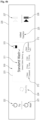
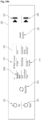
- FIG. 3 is a view showing the UI area 220 according to an embodiment of the present disclosure.
- a user interface UI is provided in the UI area 220.
- the user interface displayed in the UI area 220 may include a first power button 221, a second power button 222, a touch display 223, a switching button 224, an added function button 225, a first execution button 226, and a second execution button 227.
- the first power button 221, the second power button 222, the switching button 224, the added function button 225, the first execution button 226, and the second execution button 227 may be provided as a touch sensor or a physical button.
- the touch display 223 may be configured as a combination of a flat panel display and a touchscreen.
- the flat panel display means a thin display and may be provided in any of various forms such as LCD, PDP, AMLCD, PMLCD, OLED, and LED.
- the first power button 221 is displayed as a power icon of the washing machine 10.
- the first power button 221 receives a user input to turn the washing machine 10 on and off.
- the controller 203 may receive a turn-on or turn-off instruction for the washing machine 10.
- the second power button 222 is displayed as a power icon of the drying machine 20.
- the second power button 222 is disposed to occupy a different area from the first power button 221.
- the first power button 221 and the second power button 222 are disposed at upper and lower positions.
- the second power button 222 receives a user input to turn the drying machine 20 on and off.
- the controller 203 may receive a turn-on or turn-off instruction for the drying machine 20.
- the first power button 221 and the second power button 222 may be provided as separate touch sensors separated from a touch film provided in the touch display 223. If the first power button 221 and the second power button 222 are provided in an area separated from the touch display 223, erroneous operation of the apparatus may be reduced.
- the laundry treating apparatus 1 is placed in an environment with a lot of moisture. If the touch film forming the touch display 223 is provided in a different area from the first power button 221 and the second power button 222, erroneous operation caused by touch due to moisture may be minimized. For example, when the user turns the drying machine on and accesses the drying machine operation UI during operation of the washing machine, it is possible to prevent a problem of options of the washing machine being changed due to erroneous operation caused by touch due to moisture.
- the touch display 223 is disposed to occupy a different area from the first power button 221 and the second power button 222.
- the touch display 223 includes a touch film forming one of the input units 202 and a flat panel display forming one of the display units 201.
- the touch display 223 may display one of a washing machine operation UI for control of the washing machine 10, a drying machine operation UI for control of the drying machine 20, and a composite UI in which operation information of the washing machine 10 and operation information of the drying machine 20 are displayed on a single screen.
- the washing machine operation UI, the drying machine operation UI, and the composite UI will be described in detail later.
- the switching button 224 is disposed to occupy a different area from the first power button 221, the second power button 222, and the touch display 223.
- the switching button 224 may be provided as a separate touch sensor separated from the touch film provided in the touch display 223. If the switching button 224 is provided in an area separated from the touch display 223, erroneous operation of the apparatus may be reduced.
- the laundry treating apparatus 1 is placed in an environment with a lot of moisture. If the touch film forming the touch display 223 is provided in a different area from the switching button 224, erroneous operation caused by touch due to moisture may be minimized. For example, when the user turns the drying machine on and accesses the drying machine operation UI during operation of the washing machine, it is possible to prevent a problem of options of the washing machine being changed due to erroneous operation caused by touch due to moisture.
- the switching button 224 may be displayed as a switching icon.
- the switching button 224 receives a user input for switching a control target. When both the washing machine 10 and the drying machine 20 are in the on state, the switching button 224 is activated. If the switching button 224 is input in the state in which the washing machine operation UI is displayed on the touch display 223, the control target is switched to the drying machine 20, and the drying machine operation UI is displayed on the touch display 223. If the switching button 224 is input in the state in which the drying machine operation UI is displayed on the touch display 223, the control target is switched to the washing machine 10, and the washing machine operation UI is displayed on the touch display 223. When the power supply of at least one of the washing machine 10 or the drying machine 20 is in the off state, the switching button 224 is deactivated.
- the added function button 225 may be displayed in the form of a text icon.
- the added function button 225 is disposed to occupy a different area from the first power button 221, the second power button 222, the touch display 223, and the switching button 224.
- the added function button 225 receives a user input for setting of an added function of the washing machine 10 and/or the drying machine 20.
- an item for setting of an added function e.g., reservation or volume of notification sound
- an added function e.g., reservation or volume of notification sound
- the first execution button 226 is displayed as a start/pause icon.
- the first execution button 226 is disposed to occupy a different area from the first power button 221, the second power button 222, the touch display 223, the switching button 224, and the added function button 225.
- the first power button 221 receives a user input for execution or pause of the operation of the washing machine 10.
- the second execution button 227 is displayed as a start/pause icon.
- the second execution button 227 is disposed to occupy a different area from the first power button 221, the second power button 222, the touch display 223, the switching button 224, the added function button 225, and the first execution button 226.
- the first execution button 226 and the second execution button 227 are disposed at upper and lower positions.
- the second power button 222 receives a user input for execution or pause of the operation of the drying machine 20.
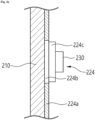
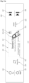
- FIG. 3A is a schematic cross-sectional view of a portion at which the switching button 224 according to an embodiment of the present disclosure is located, and shows the cross-section cut along line I-I' in FIG. 3 .
- the switching button 224 is configured such that a switching icon shape 224b is formed so as to transmit light and displayed in a set area of a light-blocking film 224a provided at the rear of the front surface portion 210 of the control panel 200.
- a touch sensor 224c may be provided on the surface on which the switching icon shape 224b is provided.
- the touch sensor 224c may be provided in any of various forms such as a capacitive type, a pressure-sensitive type, and an infrared type.
- a light-emitting element 230 is disposed at the rear of the switching icon shape 224b. Light emission of the light-emitting element 230 may be controlled to be on/off.
- the light-emitting element 230 indicates the activated state of the switching button 224.
- the light-emitting element 230 emits light when the switching button 224 is in the activated state.
- light emission of the light-emitting element 230 is controlled to be off.
- one light-emitting element 230 is disposed at the rear of the switching button 224.
- the switching button 224 has been described herein by way of example, the first power button 221, the second power button 222, the added function button 225, the first execution button 226, and the second execution button 227 may also have an identical or similar configuration to the switching button 224, and the activated states of the buttons may also be indicated by light-emitting elements.
- FIGs. 4 to 11B a portion represented by a dark-colored or thick line indicates the activated state, and a portion represented by a light-colored or thin line indicates the deactivated state.
- an input instruction may be received through the button, and in the deactivated state of the button, an input instruction may not be received through the button.
- FIG. 4 is a flowchart of a user interface and a control method of the laundry treating apparatus according to an embodiment of the present disclosure.
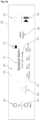
- FIGs. 4A to 4D are views showing control processes performed by the user according to the flowchart in FIG. 4 and the user interface.
- FIG. 4 An operation step for operation of the washing machine 10 will be described with reference to FIG. 4 . If the user touches the first power button 221 (refer to FIG. 4A ), the washing machine 10 is turned on (S111). If the washing machine 10 is turned on, a washing machine operation UI 310 is displayed on the touch display 223 (S112), as shown in FIG. 4B . Further, if the washing machine 10 is turned on, the first execution button 226 is activated (S113), as shown in FIG. 4B .
- the washing machine operation UI 310 is a user interface that enables control of the washing machine 10.
- the washing machine operation UI 310 includes a first screen.
- a course name 311, a course explanation 312, a treatment option 313, and an indicator 315 are displayed on the first screen.
- the course name 311 indicates the name of a preset treatment course of the washing machine 10.
- the course name 311 indicates the selected course name 311.
- the washing machine 10 may be a washing machine, and the indicated course name may be a "standard washing" course.
- the course explanation 312 indicates explanation of the treatment course corresponding to the indicated course name 311.
- the course name 311 may be "standard washing", and the course explanation 312 may be expressed as "general clothes cleaning”.
- the course explanation 312 may be disposed below the course name 311, and may be written in a smaller font than the course name 311.
- the treatment option 313 indicates detailed options of the treatment course. In the embodiment, a set number of rinsings, intensity of dehydration, water temperature, etc. may be displayed.
- the indicator 315 may indicate the currently operated object among the washing machine 10 and the drying machine 20.
- the indicator 315 may be provided in the form of an icon.
- the indicator 315 may be provided as text.
- the indicator 315 may be displayed in an upper end area of the washing machine operation UI 310.
- the indicator 315 is displayed in a first form.
- the first form may include two rectangles stacked vertically, and the lower rectangle may be colored.
- the first form may be a form colored in a first color.
- the indicator 315 provides the user with intuitive visual information about which treating apparatus is the currently operated object.
- the indicator 315 is displayed on the washing machine operation UI 310 so that the user is capable of visually recognizing that the currently displayed UI is the washing machine operation UI 310 and the control target is the washing machine 10.
- the laundry treating apparatus 1 receives a treatment course and/or a treatment option of the washing machine 10 from the user through the washing machine operation UI 310 (S120).
- the user may touch the first execution button 226 to command the washing machine 10 to operate (S130), as shown in FIG. 4C .
- the controller 203 may transmit a signal to the washing machine 10 so that the washing machine 10 operates according to the set treatment course and treatment option.
- the controller 203 may transmit a signal to the washing machine controller 19 of the washing machine 10, and the washing machine controller 19 may transmit an operation command to each of the components constituting the washing machine 10.
- the washing machine 10 executes a laundry treatment operation according to the set treatment course and treatment option (S140).
- a second screen is displayed on the washing machine operation UI 310 (refer to FIG. 4D ).
- Treatment information 317 and a time bar 317a may be displayed on the second screen.
- the indicator 315 may be further displayed on the second screen.
- the treatment information 317 is a course name, a remaining processing time, or a treatment option.
- the time bar 317a indicates a processing time.
- the time bar 317a may be displayed in a bar shape.
- the time bar 317a indicates the elapsed processing time using the length of a colored portion of the bar. As the processing time elapses, the colored portion of the time bar 317a increases in length.
- the time bar 317a may be colored in a first color.
- FIG. 5 is a flowchart of a user interface and a control method of the laundry treating apparatus according to an embodiment of the present disclosure.
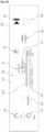
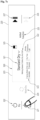
- FIGs. 5A to 5D are views showing control processes performed by the user according to the flowchart in FIG. 5 and the user interface.
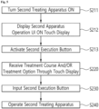
- FIG. 5 An operation step for operation of the drying machine 20 will be described with reference to FIG. 5 .
- the drying machine 20 is turned on (S211).
- a drying machine operation UI 320 is displayed on the touch display 223 (S112), as shown in FIG. 5B .
- the second execution button 227 is activated (S213), as shown in FIG. 5B .
- the drying machine operation UI 320 is a user interface that enables control of the drying machine 20.
- the drying machine operation UI 320 includes a first screen.
- a course name 321, a course explanation 322, a treatment option 323, and an indicator 325 are displayed on the first screen.
- the course name 321 indicates the name of a preset treatment course of the drying machine 20.
- the course name 321 indicates the selected course name 321.
- the drying machine 20 may be a drying machine, and the indicated course name may be a "standard drying" course.
- the course explanation 322 indicates explanation of the treatment course corresponding to the indicated course name 321.
- the course name 321 may be "standard drying", and the course explanation 322 may be expressed as "making general clothes dry and soft”.
- the course explanation 322 may be disposed below the course name 321, and may be written in a smaller font than the course name 321.
- the treatment option 323 indicates detailed options of the treatment course.
- a set drying level, a drying time, on/off of a wrinkle prevention function, etc. may be displayed.
- the indicator 325 may be displayed in an upper end area of the drying machine operation UI 320.
- the indicator 325 is displayed in a second form.
- the second form is a form different from the first form described above.
- the second form may include two rectangles stacked vertically, and the upper rectangle may be colored.
- the second form may be a form colored in a second color.
- the second color is a color different from the second color described above.
- the indicator 325 provides the user with intuitive visual information about which treating apparatus is the currently operated object.
- the indicator 325 is displayed on the drying machine operation UI 320 so that the user is capable of visually recognizing that the currently displayed UI is the drying machine operation UI 320 and the control target is the drying machine 20.
- the laundry treating apparatus 1 receives a treatment course and/or a treatment option of the drying machine 20 from the user through the drying machine operation UI 320 (S220).
- the user may touch the second execution button 227 to command the drying machine 20 to operate (S230), as shown in FIG. 5C .
- the controller 203 may transmit a signal to the drying machine 20 so that the drying machine 20 operates according to the set treatment course and treatment option.
- the controller 203 may transmit a signal to the drying machine controller 29 of the drying machine 20, and the drying machine controller 29 may transmit an operation command to each of the components constituting the drying machine 20.
- the drying machine 20 executes a laundry treatment operation according to the set treatment course and treatment option (S240).
- a second screen is displayed on the drying machine operation UI 320 (refer to FIG. 5D ).
- Treatment information 327 and a time bar 327a may be displayed on the second screen.
- the indicator 325 may be further displayed on the second screen.
- the treatment information 327 is a course name, a remaining processing time, or a treatment option.
- the time bar 327a indicates a processing time.
- the time bar 327a may be displayed in a bar shape.
- the time bar 327a indicates the elapsed processing time using the length of a colored portion of the bar. As the processing time elapses, the colored portion of the time bar 327a increases in length.
- the time bar 327a may be colored in a second color.
- FIG. 6 is a flowchart of a user interface and a control method of the laundry treating apparatus according to an embodiment of the present disclosure.
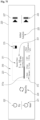
- FIGs. 6A to 6G are views showing control processes performed by the user according to the flowchart in FIG. 6 and the user interface.
- the washing machine 10 is maintained in the on state.
- the on state refers to a standby state for reception of a processing instruction or an operating state.
- the washing machine 10 may be maintained in the on state in response to an input signal received from the first power button 221 touched by the user.
- the washing machine operation UI 310 is displayed on the touch display 223, and the first execution button 226 is maintained in the activated state (S310).
- the user turns the drying machine 20 on (S321).
- the drying machine 20 is turned on in response to touch of the second power button 222 by the user (refer to FIG. 6C ).
- the switching button 224 is activated (S322).
- the drying machine operation UI 320 is displayed on the touch display 223 (S323).
- the second execution button 227 is activated (S324).
- the laundry treating apparatus 1 receives a treatment course and/or a treatment option of the drying machine 20 from the user through the drying machine operation UI 320 (S330).
- the user may touch the second execution button 227 to command the drying machine 20 to operate (S340), as shown in FIG. 6E .
- the controller 203 may transmit a signal to the drying machine 20 so that the drying machine 20 operates according to the set treatment course and treatment option.
- the controller 203 may transmit a signal to the drying machine controller 29 of the drying machine 20, and the drying machine controller 29 may transmit an operation command to each of the components constituting the drying machine 20.
- the drying machine 20 executes a laundry treatment operation according to the set treatment course and treatment option (S350).
- the laundry treating apparatus 1 determines whether the washing machine 10 is in operation (S360). If the washing machine 10 is not in operation (No), the drying machine operation UI 320 is displayed on the touch display 223 (S371). In addition, the switching button 224 is maintained in the activated state (S372).
- the second screen of the drying machine operation UI 320 may be displayed on the touch display 223 (refer to FIG. 6F ).
- Treatment information 327 and a time bar 327a may be displayed on the second screen.
- the indicator 325 may be further displayed on the second screen.
- the treatment information 327 is a course name, a remaining processing time, or a treatment option.
- the time bar 327a indicates a processing time.
- the time bar 327a may be displayed in a bar shape.
- the time bar 327a indicates the elapsed processing time using the length of a colored portion of the bar. As the processing time elapses, the colored portion of the time bar 327a increases in length.
- a composite UI 330 is displayed on the touch display 223 (S381).
- the drying machine operation UI 320 may be displayed for a set time period before the composite UI 330 is displayed (not described in the flowchart).
- the switching button 224 is deactivated (S382).
- the composite UI 330 displays the operation information of the washing machine 10 and the operation information of the drying machine 20 on a single screen.
- the composite UI 330 is displayed when both the washing machine 10 and the drying machine 20 are in operation.
- the composite UI 330 is provided with a first area 331 and a second area 332.
- the operation information of the washing machine 10 is displayed in the first area 331.
- the operation information of the drying machine 20 is displayed in the second area 332.
- the first area 331 and the second area 332 are displayed on a single screen.
- the first area 331 occupies an upper area of the composite UI 330
- the second area 332 occupies a lower area of the composite UI 330.
- Treatment information and a time bar 331a may be displayed in the first area 331.
- the treatment information includes a remaining processing time.
- the time bar 331a indicates a processing time.
- the time bar 331a may be displayed in a bar shape.
- the time bar 331a indicates the elapsed processing time using the length of a colored portion of the bar. As the processing time elapses, the colored portion of the time bar 331a increases in length.
- the time bar 331a may be colored in the first color.
- the first area 331 may receive user touch. When the user touch input is received from the first area 331, the touch display 223 is controlled to display the washing machine operation UI 310.
- Treatment information and a time bar 332a may be displayed in the second area 332.
- the treatment information includes a remaining processing time.
- the time bar 332a indicates a processing time.
- the time bar 332a may be displayed in a bar shape.
- the time bar 332a indicates the elapsed processing time using the length of a colored portion of the bar. As the processing time elapses, the colored portion of the time bar 332a increases in length.
- the time bar 332a may be colored in the second color.
- the second area 332 may receive user touch. When the user touch input is received from the second area 332, the touch display 223 is controlled to display the drying machine operation UI 320.
- FIG. 7 is a flowchart of a user interface and a control method of the laundry treating apparatus according to an embodiment of the present disclosure.
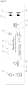
- FIGs. 7A to 7G are views showing control processes performed by the user according to the flowchart in FIG. 7 and the user interface.
- the drying machine 20 is maintained in the on state.
- the on state refers to a standby state for reception of a processing instruction or an operating state.
- the drying machine 20 may be maintained in the on state in response to an input signal received from the second power button 222 touched by the user.
- the drying machine operation UI 320 is displayed on the touch display 223, and the second execution button 227 is maintained in the activated state (S410).
- the user turns the washing machine 10 on (S421).
- the washing machine 10 is turned on in response to touch of the first power button 221 by the user (refer to FIG. 7C ).
- the switching button 224 is activated (S722).
- the washing machine operation UI 310 is displayed on the touch display 223 (S423).
- the first execution button 226 is activated (S424).
- the laundry treating apparatus 1 receives a treatment course and/or a treatment option of the washing machine 10 from the user through the washing machine operation UI 310 (S430).
- the user may touch the first execution button 226 to command the washing machine 10 to operate (S440), as shown in FIG. 7E .
- the controller 203 may transmit a signal to the washing machine 10 so that the washing machine 10 operates according to the set treatment course and treatment option.
- the controller 203 may transmit a signal to the washing machine controller 19 of the washing machine 10, and the washing machine controller 19 may transmit an operation command to each of the components constituting the washing machine 10.
- the washing machine 10 executes a laundry treatment operation according to the set treatment course and treatment option (S450).
- the laundry treating apparatus 1 determines whether the drying machine 20 is in operation (S460). If the drying machine 20 is not in operation (No), the washing machine operation UI 310 is displayed on the touch display 223 (S471). In addition, the switching button 224 is maintained in the activated state (S472).
- the second screen of the washing machine operation UI 310 may be displayed on the touch display 223 (refer to FIG. 7F ).
- Treatment information 317 and a time bar 317a may be displayed on the second screen.
- the indicator 325 may be further displayed on the second screen.
- the treatment information 317 is a course name, a remaining processing time, or a treatment option.
- the time bar 317a indicates a processing time.
- the time bar 317a may be displayed in a bar shape.
- the time bar 317a indicates the elapsed processing time using the length of a colored portion of the bar. As the processing time elapses, the colored portion of the time bar 317a increases in length.
- a composite UI 330 is displayed on the touch display 223 (S481).
- the washing machine operation UI 310 may be displayed for a set time period before the composite UI 330 is displayed (not described in the flowchart).
- the switching button 224 is deactivated (S482).
- the composite UI 330 displays the operation information of the washing machine 10 and the operation information of the drying machine 20 on a single screen.
- the composite UI 330 is displayed when both the washing machine 10 and the drying machine 20 are in operation.
- the composite UI 330 is provided with a first area 331 and a second area 332.
- the operation information of the washing machine 10 is displayed in the first area 331.
- the operation information of the drying machine 20 is displayed in the second area 332.
- the first area 331 and the second area 332 are displayed on a single screen.
- the first area 331 occupies an upper area of the composite UI 330
- the second area 332 occupies a lower area of the composite UI 330.
- Treatment information and a time bar 331a may be displayed in the first area 331.
- the treatment information includes a remaining processing time.
- the time bar 331a indicates a processing time.
- the time bar 331a may be displayed in a bar shape.
- the time bar 331a indicates the elapsed processing time using the length of a colored portion of the bar. As the processing time elapses, the colored portion of the time bar 331a increases in length.
- the time bar 331a may be colored in the first color.
- the first area 331 may receive user touch. When the user touch input is received from the first area 331, the touch display 223 is controlled to display the washing machine operation UI 310.
- Treatment information and a time bar 332a may be displayed in the second area 332.
- the treatment information includes a remaining processing time.
- the time bar 332a indicates a processing time.
- the time bar 332a may be displayed in a bar shape.
- the time bar 332a indicates the elapsed processing time using the length of a colored portion of the bar. As the processing time elapses, the colored portion of the time bar 332a increases in length.
- the time bar 332a may be colored in the second color.
- the second area 332 may receive user touch. When the user touch input is received from the second area 332, the touch display 223 is controlled to display the drying machine operation UI 320.
- FIG. 8 is a flowchart of a user interface and a control method of the laundry treating apparatus according to an embodiment of the present disclosure.
- FIGs. 8A to 8F are views showing control processes performed by the user according to the flowchart in FIG. 8 and the user interface.
- the washing machine 10 is maintained in the on state.
- the on state refers to a standby state for reception of a processing instruction or an operating state.
- the washing machine 10 may be maintained in the on state in response to an input signal received from the first power button 221 touched by the user.
- the washing machine operation UI 310 is displayed on the touch display 223, and the first execution button 226 is maintained in the activated state (S510).
- the user turns the drying machine 20 on (S521).
- the drying machine 20 is turned on in response to touch of the second power button 222 by the user (refer to FIG. 8C ).
- the drying machine 20 is turned on, the switching button 224 is activated (S522).
- the second execution button 227 is activated.
- the drying machine operation UI 320 is displayed on the touch display 223 (S523).
- a process in which an operation instruction is input from the user is a process in which the user operates the drying machine operation UI 320 in order to, for example, select a treatment course and/or a treatment option through the drying machine operation UI 320.
- Inputting an operation instruction by the user may further include a concept of inputting an operation instruction by touching the second execution button 227.
- FIG. 9 is a flowchart of a user interface and a control method of the laundry treating apparatus according to an embodiment of the present disclosure.
- FIGs. 9A to 9E are views showing control processes performed by the user according to the flowchart in FIG. 9 and the user interface.
- the drying machine 20 is maintained in the on state.
- the on state refers to a standby state for reception of a processing instruction or an operating state.
- the drying machine 20 may be maintained in the on state in response to an input signal received from the second power button 222 touched by the user.
- the drying machine operation UI 320 is displayed on the touch display 223, and the second execution button 227 is maintained in the activated state (S610).
- the user turns the washing machine 10 on (S621).
- the washing machine 10 is turned on in response to touch of the first power button 221 by the user (refer to FIG. 9C ).
- the switching button 224 is activated (S622).
- the first execution button 226 is activated.
- the washing machine operation UI 310 is displayed on the touch display 223 (S623).
- a process in which an operation instruction is input from the user is a process in which the user operates the washing machine operation UI 310 in order to, for example, select a treatment course and/or a treatment option through the washing machine operation UI 310.
- Inputting an operation instruction by the user may further include a concept of inputting an operation instruction by touching the first execution button 226.
- FIGs. 10A and 10B are views showing a user interface of the laundry treating apparatus according to an embodiment of the present disclosure and a process of, by the user, controlling the same.
- the washing machine operation UI 310 may display one or more letters in a first text color 319a distinguished from a basic text color.
- the laundry treating apparatus 1 may receive user touch input from a view-all button 311a located on the right of the course name 311.
- a list of settable courses may be displayed on the washing machine operation UI 310.
- the currently selected course e.g., "standard washing”
- the user may visually recognize which course he or she has selected.
- FIGs. 11A and 11B are views showing a user interface of the laundry treating apparatus according to an embodiment of the present disclosure and a process of, by the user, controlling the same.
- the drying machine operation UI 320 may display one or more letters in a second text color 329a distinguished from the basic text color and the first text color.
- the laundry treating apparatus 1 may receive user touch input from a view-all button 321a located on the right of the course name 321.
- a list of settable courses may be displayed on the drying machine operation UI 320.
- the currently selected course e.g., "standard drying”
- the user may visually recognize which course he or she has selected.
- the washing machine operation UI 310 is expressed in the first text color
- the drying machine operation UI 320 is expressed in the second text color, so the user may visually and intuitively recognize which apparatus is currently being operated.
- control flow of the laundry treating apparatus 1 may be implemented by any one of the controller 203, the washing machine controller 19, and the drying machine controller 29.
- control flow of the laundry treating apparatus 1 may be implemented in the form of a recording medium storing instructions executable by a computer.
- the instructions may be stored in the form of program code, and when executed by a processor, the instructions may generate a program module to perform operations of the disclosed embodiments.
- the recording medium may be implemented as a computer-readable recording medium.
Landscapes
- Engineering & Computer Science (AREA)
- Textile Engineering (AREA)
- Control Of Washing Machine And Dryer (AREA)
- Main Body Construction Of Washing Machines And Laundry Dryers (AREA)
Abstract
Description
- The present disclosure relates to a laundry treating apparatus.
- A laundry treating apparatus is an apparatus that receives laundry, such as clothes and bedding, in a drum to perform treatment necessary for the laundry, such as removal of contaminants from the laundry or drying of the laundry.
- When a laundry treating apparatus is designed to remove contaminants from laundry, the laundry treating apparatus may perform processes such as washing, rinsing, dehydration, and drying. The laundry treating apparatus may include a cabinet defining the external appearance thereof, a tub accommodated in the cabinet, a drum rotatably mounted in the tub and configured to receive laundry, and a detergent supply device configured to supply detergent to the interior of the drum. If the drum is rotated by a motor in the state in which wash water is supplied to the laundry received in the drum, dirt on the laundry may be removed by friction with the drum and the wash water.
- When a laundry treating apparatus is designed to dry laundry, the laundry treating apparatus may supply dry air to the laundry to remove moisture from the laundry. The laundry treating apparatus may include a cabinet, a drum rotatably disposed in the cabinet, and a heating device configured to heat or dry air supplied to the laundry. As the dry air is supplied to the laundry received in the drum, moisture in the laundry may be evaporated and removed by the dry air, and thus water may be removed from the laundry.
- A laundry treating apparatus provided with multiple treating apparatuses is disclosed in related art document
KR 10-2008-0021921 A1 - That is, the laundry treating apparatus disclosed in the above related art document is configured such that each of the multiple treating apparatuses, which are provided separately from each other, has an operation unit and a display unit. In this case, however, a user needs to individually check the states of the multiple treating apparatuses and to individually operate the multiple treating apparatuses. In addition, it may be inconvenient for the user to operate the multiple treating apparatuses in association with each other.
- Therefore, in a laundry treating apparatus provided with multiple treating apparatuses, it is an important task to improve user convenience in checking the operational states of the multiple treating apparatuses or operating the multiple treating apparatuses and to secure an efficient arrangement relationship between components of the multiple treating apparatuses and a stable and effective coupling relationship between the multiple treating apparatuses.
- In the case in which a control panel capable of controlling all of multiple treating apparatuses constituting a laundry treating apparatus is provided, a first button for activating a user interface for control of a washing machine, a first light-emitting element (e.g., LED) for indicating the activation state of the first button, a second button for activating a user interface for control of a drying machine, and a second light-emitting element for indicating the activation state of the second button are provided. However, because two buttons are provided in order to indicate the activation states of the treating apparatuses, many physical display spaces are required, and because two light-emitting elements are also required, manufacturing costs are increased. An aspect of the present disclosure is directed to providing a laundry treating apparatus capable of reducing the number of physical display devices for indicating the activation states of the treating apparatuses, thereby providing a simple and clear design, and capable of reducing the number of light-emitting elements, thereby reducing manufacturing costs.
- In the case in which a user interface is provided at a control panel capable of controlling all of multiple treating apparatuses constituting a laundry treating apparatus, an aspect of the present disclosure is directed to providing a laundry treating apparatus capable of implementing a simple user interface and providing an interior effect when placed in an installation environment.
- In the case in which a user interface is provided at a control panel capable of controlling all of multiple treating apparatuses constituting a laundry treating apparatus, an aspect of the present disclosure is directed to providing a highly intuitive laundry treating apparatus capable of displaying an activated user interface on a touch display and enabling a user to visually recognize the treating apparatus corresponding to the activated user interface.
- In the case in which a user interface is provided at a control panel capable of controlling all of multiple treating apparatuses constituting a laundry treating apparatus, the present disclosure provides a layout structure capable of reducing erroneous recognition of a touch input due to moisture.
- The aspects of the present disclosure are not limited to those mentioned above, and other aspects not mentioned herein will be clearly understood by those skilled in the art from the following description.
- The present disclosure provides a laundry treating apparatus. In an embodiment, the laundry treating apparatus includes a washing machine including a washing machine front panel provided on a front side thereof and a first drum provided therein to receive laundry, a drying machine disposed on the washing machine, the drying machine including a drying machine front panel provided on a front side thereof and a second drum provided therein to receive laundry, and a control panel provided between the washing machine front panel and the drying machine front panel, the control panel being configured to provide a user interface (UI) of at least one of the washing machine or the drying machine, wherein the control panel includes a flat panel display configured to display one of a washing machine operation UI for operation of the washing machine and a drying machine operation UI for operation of the drying machine and a switching button. If input is received from the switching button in the state in which the washing machine operation UI is displayed on the flat panel display, the flat panel display displays the drying machine operation UI, and if input is received from the switching button in the state in which the drying machine operation UI is displayed on the flat panel display, the flat panel display displays the washing machine operation UI.
- In an embodiment, when both the washing machine and the drying machine are in the on state, the switching button may be activated.
- In an embodiment, when at least one of the washing machine or the drying machine is in the off state, the switching button may be deactivated.
- In an embodiment, in the state in which one of the washing machine and the drying machine is in operation, when the remaining one of the washing machine and the drying machine is turned on, the switching button may be activated.
- A laundry treating apparatus in accordance with another aspect of the present disclosure includes a washing machine including a washing machine front panel provided on a front side thereof and a first drum provided therein to receive laundry, a drying machine disposed on the washing machine, the drying machine including a drying machine front panel provided on a front side thereof and a second drum provided therein to receive laundry, and a control panel provided between the washing machine front panel and the drying machine front panel, the control panel being configured to provide a user interface (UI) of at least one of the washing machine or the drying machine, wherein the control panel includes a flat panel display configured to display one of a washing machine operation UI for operation of the washing machine and a drying machine operation UI for operation of the drying machine, and when both the washing machine and the drying machine are in the on state, the control panel is activated.
- In an embodiment, the control panel may include a touch film located on a front surface of the flat panel display.
- In an embodiment, the laundry treating apparatus is configured such that the flat panel display forms one of display units of the user interface (UI) and the touch film forms one of input units of the user interface (UI).
- In an embodiment, the switching button may be disposed to occupy a different area from the touch film.
- In an embodiment, the switching button may be provided as a touch sensor separated from the touch film.
- In an embodiment, the control panel may include a power button configured to receive a user input to turn the washing machine or the drying machine on and off and an execution button configured to receive a user input to execute or pause operation of the washing machine or the drying machine, and the power button and the execution button may be provided as touch sensors separated from the touch film.
- In an embodiment, a light-emitting element disposed at the rear of the switching button to indicate the activated state of the switching button may be further included.
- In an embodiment, the light-emitting element may emit light in the activated state of the switching button.
- In an embodiment, the light-emitting element may not emit light in the deactivated state of the switching button.
- In an embodiment, when the flat panel display displays the remaining one of the washing machine operation UI and the drying machine operation UI in response to input of the switching button, if input is not received from a user for a preset time period or longer, the flat panel display may again display one of the washing machine operation UI and the drying machine operation UI.
- In an embodiment, if a user input is not received for a preset time period or longer in the activated state of the switching button, the switching button may be deactivated.
- In an embodiment, the flat panel display may output an indicator indicating the currently operated object among the washing machine and the drying machine.
- In an embodiment, the indicator may be displayed in a first form in the washing machine operation UI, and may be displayed in a second form different from the first form in the drying machine operation UI.
- In an embodiment, the washing machine operation UI may display one or more letters in a first text color distinguished from a basic text color, and the drying machine operation UI may display one or more letters in a second text color distinguished from the basic text color and the first text color.
- In an embodiment, the flat panel display may further display a composite UI in which operation information of the washing machine and operation information of the drying machine are displayed on a single screen.
- In an embodiment, according to
claim 19, the composite UI may be displayed when both the washing machine and the drying machine are in operation. - In an embodiment, the switching button may be deactivated in the state in which the composite UI is displayed.
- In an embodiment, the composite UI may include a first area and a second area, which is a different area from the first area. The operation information of the washing machine may be displayed in the first area, and
the operation information of the drying machine may be displayed in the second area. - In an embodiment, when a user touch input is received from the first area, the laundry treating apparatus may display the washing machine operation UI on the flat panel display, and when a user touch input is received from the second area, the laundry treating apparatus may display the drying machine operation UI on the flat panel display.
- In an embodiment, the first area may be an upper area of the composite UI, and the second area may be a lower area of the composite UI.
- In an embodiment, the control panel may further include an execution button configured to receive a user input to execute or pause operation of the washing machine or the drying machine.
- In an embodiment, the execution button may include a first execution button configured to receive a user input to execute or pause operation of the washing machine and a second execution button configured to receive a user input to execute or pause operation of the drying machine.
- In an embodiment, the control panel may further include a power button configured to receive a user input to turn the washing machine or the drying machine on and off, and the flat panel display may be disposed to occupy a different area from the power button.
- In an embodiment, the power button may be provided at a position spaced apart from the flat panel display in one direction, and the switching button may be located between the power button and the flat panel display.
- In an embodiment, an execution button configured to receive a user input to execute or pause operation of the washing machine or the drying machine may be further included, and the execution button may be provided at a position spaced apart from the flat panel display in the opposite direction.
- In an embodiment, the power button may include a first power button configured to receive a user input to turn the washing machine on and off and a second power button configured to receive a user input to turn the drying machine on and off.
- In an embodiment, when a user input for turn-on of the washing machine is received from the first power button, the washing machine operation UI may be displayed on the flat panel display to enable control of the washing machine, and when a user input for turn-on of the drying machine is received from the second power button, the drying machine operation UI may be displayed on the flat panel display to enable control of the drying machine.
- A laundry treating apparatus in accordance with a further aspect of the present disclosure includes a washing machine including a washing machine front panel provided on a front side thereof and a first drum provided therein to receive laundry, a drying machine disposed on the washing machine, the drying machine including a drying machine front panel provided on a front side thereof and a second drum provided therein to receive laundry, and a control panel provided between the washing machine front panel and the drying machine front panel, the control panel being configured to provide a user interface (UI) of at least one of the washing machine or the drying machine, wherein the control panel includes a power button configured to receive a user input to turn the washing machine or the drying machine on and off, a flat panel display configured to display one of a washing machine operation UI for operation of the washing machine and a drying machine operation UI for operation of the drying machine, and an execution button configured to receive a user input to execute or pause operation of the washing machine or the drying machine, the power button is provided at a position spaced apart from the flat panel display in one direction, and the execution button is provided at a position spaced apart from the flat panel display in the opposite direction.
- In an embodiment, a switching button configured to receive a switching instruction from a user to display the remaining one of the washing machine operation UI and the drying machine operation UI in the state in which one of the washing machine operation UI and the drying machine operation UI is displayed on the flat panel display may be included, and the switching button may be located between the power button and the flat panel display.
- In an embodiment, the control panel may include a touch film located on a front surface of the flat panel display, and the switching button may be provided as a touch sensor separated from the touch film.
- In an embodiment, the control panel may include a touch film located on a front surface of the flat panel display, and the power button and the execution button may be provided as touch sensors separated from the touch film.
- According to embodiments of the present disclosure, in the case in which a control panel capable of controlling all of multiple treating apparatuses constituting a laundry treating apparatus is provided, because the number of physical display devices for indicating the activation states of the treating apparatuses is reduced, a simple and clear design may be provided, and because the number of light-emitting elements indicating the activation states is reduced, manufacturing costs may be reduced.
- According to embodiments of the present disclosure, in the case in which a user interface is provided at a control panel capable of controlling all of multiple treating apparatuses constituting a laundry treating apparatus, a simple user interface may be implemented, and an interior effect may be provided when the laundry treating apparatus is placed in an installation environment.
- According to embodiments of the present disclosure, in the case in which a user interface is provided at a control panel capable of controlling all of multiple treating apparatuses constituting a laundry treating apparatus, because a user is capable of visually recognizing the treating apparatus corresponding to an activated user interface, intuitive use is possible, and use convenience is improved.
- According to embodiments of the present disclosure, in the case in which a user interface is provided at a control panel capable of controlling all of multiple treating apparatuses constituting a laundry treating apparatus, a layout structure capable of reducing erroneous recognition of a touch input due to moisture may be achieved.
- The effects of the present disclosure are not limited to the above-mentioned effects, and other effects not mentioned herein will be clearly understood by those skilled in the art to which the present disclosure pertains from the present specification and the accompanying drawings.
-
-
FIG. 1 is a perspective view showing a laundry treating apparatus according to an embodiment of the present disclosure. -
FIG. 2 is a diagram schematically showing relationships between a control panel, a washing machine, and a drying machine according to an embodiment of the present disclosure. -
FIG. 3 is a view showing a UI area according to an embodiment of the present disclosure. -
FIG. 3A is a cross-sectional view taken along line I-I' inFIG. 3 .FIG. 4 is a flowchart of a user interface and a control method of the laundry treating apparatus according to an embodiment of the present disclosure. -
FIGs. 4A to 4D are views showing control processes performed by a user according to the flowchart inFIG. 4 and a user interface. -
FIG. 5 is a flowchart of a user interface and a control method of the laundry treating apparatus according to an embodiment of the present disclosure. -
FIGs. 5A to 5D are views showing control processes performed by a user according to the flowchart inFIG. 5 and a user interface. -
FIG. 6 is a flowchart of a user interface and a control method of the laundry treating apparatus according to an embodiment of the present disclosure. -
FIGs. 6A to 6G are views showing control processes performed by a user according to the flowchart inFIG. 6 and a user interface. -
FIG. 7 is a flowchart of a user interface and a control method of the laundry treating apparatus according to an embodiment of the present disclosure. -
FIGs. 7A to 7G are views showing control processes performed by a user according to the flowchart inFIG. 7 and a user interface. -
FIG. 8 is a flowchart of a user interface and a control method of the laundry treating apparatus according to an embodiment of the present disclosure. -
FIGs. 8A to 8F are views showing control processes performed by a user according to the flowchart inFIG. 8 and a user interface. -
FIG. 9 is a flowchart of a user interface and a control method of the laundry treating apparatus according to an embodiment of the present disclosure. -
FIGs. 9A to 9E are views showing control processes performed by a user according to the flowchart inFIG. 9 and a user interface. -
FIGs. 10A and10B are views showing a user interface of the laundry treating apparatus according to an embodiment of the present disclosure and a process of, by a user, controlling the same. -
FIGs. 11A and11B are views showing a user interface of the laundry treating apparatus according to an embodiment of the present disclosure and a process of, by a user, controlling the same. - Hereinafter, embodiments of the present disclosure will be described in detail with reference to the accompanying drawings so that those skilled in the art to which the present disclosure pertains may easily carry out the embodiments.
- However, the present disclosure is not limited to aspects disclosed herein and may be implemented in various different forms. In the drawings, in order to clearly describe the present disclosure, descriptions of elements which are not related to the present disclosure are omitted, and the same or similar elements are denoted by the same reference numerals throughout the specification.
- In the following description of the embodiments, redundant description of the same elements will be omitted.
- When an element is referred to as being "connected to" or "coupled to" another element, it may be directly connected to or coupled to the other element, or intervening elements may be present. In contrast, when an element is referred to as being "directly connected to" or "directly coupled to" another element, there may be no intervening elements present.
- Further, the terminology used herein is for the purpose of describing particular embodiments only and is not intended to be limiting.
- As used herein, singular forms may be intended to include plural forms as well, unless the context clearly indicates otherwise.
- Further, in the following description of the embodiments, the terms "comprising," "including," or "having" are inclusive and therefore specify the presence of stated features, numbers, steps, operations, elements, components, or combinations thereof, but do not preclude the presence or addition of one or more other features, numbers, steps, operations, elements, components, or combinations thereof.
- Further, as used herein, the term "and/or" includes any and all combinations of one or more of the associated listed items. In the following description of the embodiments, "a or b" may include "a", "b", or "both a and b".
-
FIG. 1 shows alaundry treating apparatus 1 according to an embodiment of the present disclosure. In the embodiment of the present disclosure, thelaundry treating apparatus 1 includes awashing machine 10, a dryingmachine 20, and acontrol panel 200. - In the description of the present disclosure, a forward direction (+X), a backward direction (-X), a first lateral direction (+Y), a second lateral direction (-Y), an upward direction (+Z), and a downward direction (Z) of each component may be defined as the same directions as those of the other components. For example, the forward-backward direction (+X, -X) of the
washing machine 10 may be defined as the same direction as the forward-backward direction of the dryingmachine 20 and the forward-backward direction of thecontrol panel 200, and the lateral direction (Y) and the upward-downward direction (Z) may also be defined in the same manner. - The
washing machine 10 and the dryingmachine 20 may be implemented in various types of laundry treating apparatuses, such as a washing machine for washing laundry and/or a drying machine for drying laundry. Thewashing machine 10 may be a washing machine, and the dryingmachine 20 may be a drying machine. Both thewashing machine 10 and the dryingmachine 20 may be washing machines or drying machines. Thewashing machine 10 may be a drying machine, and the dryingmachine 20 may be a washing machine. Thewashing machine 10 and the dryingmachine 20 may be various other types of laundry treating apparatuses. - In the embodiment, the
washing machine 10 located at a lower position may correspond to a washing machine for washing laundry. Thewashing machine 10 may be provided therein with afirst drum 12 in which laundry is received and atub 14. Thefirst drum 12 in thewashing machine 10 may be rotatably provided in thetub 14. The dryingmachine 20 is located on thewashing machine 10. Thewashing machine 10 supports the dryingmachine 20. The dryingmachine 20 may correspond to a drying machine for drying laundry. The dryingmachine 20 may be provided therein with afirst drum 12 in which laundry is received and atub 14. - The
washing machine 10 may include afirst cabinet 110 forming the external appearance thereof. Thefirst cabinet 110 may be provided on a front side thereof with a washingmachine front panel 112. The washingmachine front panel 112 may include a laundry opening communicating with thefirst drum 12. The laundry opening may be opened and closed by afirst cabinet door 17. Thefirst drum 12 of thewashing machine 10 according to the embodiment has a rotation axis parallel to the forward-backward direction (+X, -Y). - A first
lateral panel 115 may be provided on each of both sides of thewashing machine 10 in the lateral direction Y, a first rear panel (not shown) may be provided on a rear side of thewashing machine 10, a first upper panel (not shown) may be provided on an upper side of thewashing machine 10, and a first lower panel (not shown) may be provided on a lower side of thewashing machine 10. - The washing
machine front panel 112, the firstlateral panel 115, the first rear panel (not shown), the first upper panel 119, and the first lower panel (not shown) may be assembled with one another to form thefirst cabinet 110 and may have coupling relationships with one another. Thefirst cabinet 110 may have a space defined therein to accommodate internal components constituting thewashing machine 10, such as thefirst drum 12. - Laundry to be treated may be introduced into the
first cabinet 110 through the laundry opening of thewashing machine 10, and may be received in thefirst drum 12, and a treatment process may be performed by thewashing machine 10. - A detergent opening may be formed in the washing
machine front panel 112, and adetergent storage unit 30 is inserted into and received in the detergent opening. In thelaundry treating apparatus 1 according to the embodiment, thewashing machine 10 may be disposed on the ground, and thedetergent storage unit 30 may be located at a higher position than the laundry opening of thewashing machine 10 in order to facilitate introduction and withdrawal of thedetergent storage unit 30. Thedetergent storage unit 30 may be located between the laundry opening of thewashing machine 10 and thecontrol panel 200. That is, thedetergent storage unit 30 may be located at a higher position than the laundry opening of thewashing machine 10 and may be located at a lower position than thecontrol panel 200. Thedetergent storage unit 30 may be introduced into or withdrawn out of thefirst cabinet 110 by the user. For example, the user may withdraw thedetergent storage unit 30 out of thefirst cabinet 110 to store detergent in thedetergent storage unit 30, and then may introduce thedetergent storage unit 30 back into thefirst cabinet 110. - In the embodiment, a filter opening, into which a
filter unit 40 for collecting foreign substances from wash water is inserted, is formed in the washingmachine front panel 112, and thefilter unit 40 is inserted into and received in the filter opening. Thefilter unit 40 may be provided at a part of a lower portion of the washingmachine front panel 112. Thefilter unit 40 may be introduced into thefirst cabinet 110 through the filter opening, and may be connected to a flow path for wash water discharged from thetub 14. Thefilter unit 40 may remove foreign substances from wash water discharged from thetub 14 after the washing process is performed. However, the role of thefilter unit 40 is not necessarily limited thereto. Thefilter unit 40 may be provided to remove foreign substances from various objects as needed. For example, thefilter unit 40 may be provided to remove foreign substances from wash water for the washing process before the washing process is performed. - The user may introduce or withdraw the
filter unit 40 into or out of thefirst cabinet 110 through the filter opening. The withdrawnfilter unit 40 may be reused after cleaning or may be replaced. The introduction/withdrawal frequency of thefilter unit 40 may be lower than that of thedetergent storage unit 30. Accordingly, in the embodiment of the present disclosure, the detergent opening, into and out of which thedetergent storage unit 30 is introduced and withdrawn with a higher frequency, may be disposed at an upper portion of the washingmachine front panel 112. In addition, the filter opening, into and out of which thefilter unit 40 is introduced and withdrawn with a lower frequency, may be disposed at a lower portion of the washingmachine front panel 112, thereby implementing the structure of the washingmachine front panel 112 capable of improving use convenience and efficiency of space utilization. - Further, a wash water discharge flow path, which is connected to the
tub 14 in thefirst cabinet 110, may be located at a lower portion in thefirst cabinet 110 in order to facilitate discharge of the wash water. In the embodiment of the present disclosure, thefilter unit 40 may be provided at a lower portion of thefirst cabinet 110 and thus may be efficiently connected to the wash water discharge flow path. - The
washing machine 10 may be provided with awashing machine controller 19. Thewashing machine controller 19 is a component configured to control various devices constituting thewashing machine 10. Thewashing machine controller 19 is disposed in thefirst cabinet 110. Thewashing machine controller 19 may include a circuit board and electronic components mounted on the circuit board. In the embodiment, thewashing machine controller 19 may retrieve information that corresponds to an operation signal received from thecontrol panel 200 from a memory, and may perform control of the device in response to the operation signal. Thewashing machine controller 19 may transmit the state of thewashing machine 10 to thecontrol panel 200. - The drying
machine 20 may include asecond cabinet 120 forming the external appearance thereof. Thesecond cabinet 120 may be provided on a front side thereof with a dryingmachine front panel 122. The dryingmachine front panel 122 may include a laundry opening communicating with thesecond drum 22. The laundry opening may be opened and closed by asecond cabinet door 27. - A second
lateral panel 125 may be provided on each of both sides of the dryingmachine 20 in the lateral direction (+Y, -Y). A second rear panel (not shown) may be provided on a rear side of the dryingmachine 20, a secondupper panel 127 may be provided on an upper side of the dryingmachine 20, and a second lower panel (not shown) may be provided on a lower side of the dryingmachine 20. - The drying
machine front panel 122, the secondlateral panel 125, the second rear panel (not shown), the secondupper panel 127, and the second lower panel (not shown) may be assembled with one another to form thesecond cabinet 120, and may have coupling relationships with one another. Thesecond cabinet 120 may have a space defined therein to accommodate internal components constituting the dryingmachine 20, such as thesecond drum 22. - Laundry to be treated may be introduced into the
second cabinet 120 through the laundry opening of the dryingmachine 20, and may be received in thesecond drum 22. Treatment processes such as washing and drying may be performed on the laundry received in thesecond drum 22 by the dryingmachine 20. - In the drying
machine 20 according to the embodiment, the laundry opening is provided on the dryingmachine front panel 122 together with thesecond cabinet door 27. Thesecond drum 22 accommodated in the dryingmachine 20 has a rotation axis parallel to the forward-backward direction (X). - The drying
machine 20 is disposed on thewashing machine 10. In the embodiment, the lower side of thewashing machine 10 may be coupled to the upper side of the dryingmachine 20. The upper side of thewashing machine 10 may have a structure for supporting the dryingmachine 20. For example, the first upper panel (not shown) of thewashing machine 10 may have a structure for directly or indirectly supporting the second lower panel (not shown) of the dryingmachine 20. - The drying
machine 20 may be provided with a dryingmachine controller 29. The dryingmachine controller 29 is a component configured to control various devices constituting the dryingmachine 2. The dryingmachine controller 29 is disposed in thesecond cabinet 120. The dryingmachine controller 29 may include a circuit board and electronic components mounted on the circuit board. In the embodiment, the dryingmachine controller 29 may retrieve information that corresponds to an operation signal received from thecontrol panel 200 from a memory, and may perform control of the device in response to the operation signal. The dryingmachine controller 29 may transmit the state of the dryingmachine 20 to thecontrol panel 200. - The
control panel 200 is disposed between the washingmachine front panel 112 and the dryingmachine front panel 122. Because thecontrol panel 200 is provided between the washingmachine front panel 112 and the dryingmachine front panel 122, thecontrol panel 200 may be located at a height substantially corresponding to the user's waist, so the user may conveniently operate thecontrol panel 200. Thecontrol panel 200 may be signally connected to at least one of thewashing machine 10 or the dryingmachine 20. In the embodiment, thecontrol panel 200 is signally connected to thewashing machine 10 and the dryingmachine 20. In the embodiment, thecontrol panel 200 is signally connected to thewashing machine controller 19 and/or the dryingmachine 20. - A
UI area 220, in which a user interface (UI) is displayed, is provided on afront surface portion 210 of thecontrol panel 200. -
FIG. 2 is a diagram schematically showing the relationships between thecontrol panel 200, thewashing machine 10, and the dryingmachine 20 according to an embodiment of the present disclosure. - According to the embodiment of the present disclosure, the
control panel 200 may include adisplay unit 210, aninput unit 202, and acontroller 203. - The
display unit 201 is a component configured to display the state of thewashing machine 10 and/or the state of the dryingmachine 20. Thedisplay unit 201 is provided in theUI area 220 of thecontrol panel 200. Thedisplay unit 201 displays operation information of at least one of the washing machine or the drying machine and the user interface (UI). - The
input unit 202 is a component configured to receive, from the user, an operation instruction for control of thewashing machine 10 and/or the dryingmachine 20. Theinput unit 202 is provided at thecontrol panel 200. Theinput unit 202 may be provided as a touchscreen. Theinput unit 202 may be provided as a touch sensor. Theinput unit 202 may be provided as a physical button. - The
controller 203 may be provided in thecontrol panel 200, i.e., on the rear surface of thefront surface portion 210. One ormore controllers 203 may be provided. Thecontroller 203 may be electrically connected to thewashing machine 10 and/or the dryingmachine 20 to exchange a signal therewith. Thecontact area 203 may be connected to thedisplay unit 201 and/or theinput unit 202 to exchange a signal therewith. The aforementioned signal may be a control instruction, a user input, state information of the apparatus, or the like. Thecontroller 203 may sense an operation signal from theinput unit 202. Thecontroller 203 may retrieve information that corresponds to the input operation signal from the memory. Thecontroller 203 may transmit display data to thedisplay unit 201. Thedisplay unit 201 may display the operational state of thewashing machine 10, the operational state of the dryingmachine 20, and/or the content of the instruction input by the user in response to the display data received from thecontroller 203. Thecontroller 203 may change the states of the components constituting theinput unit 202 to activated states or deactivated states. Thecontroller 203 may change the states of the components constituting thedisplay unit 201 to activated states or deactivated states. Thecontroller 203 may include a circuit board and electronic components mounted on the circuit board. - Although the
controller 203 has been described in the embodiment as being included in thecontrol panel 200, thecontroller 203 may not be classified as thecontrol panel 200. Further, thecontroller 203 may be provided at a position other than thecontrol panel 200. Thecontroller 203 may be provided in thewashing machine 10 and/or the dryingmachine 20. Further, thecontroller 203 may be provided in each of thecontrol panel 200, thewashing machine 10, and the dryingmachine 20. Thecontroller 203 may be integrated with thewashing machine controller 19 and/or the dryingmachine controller 29. Alternatively, thecontroller 203 may be understood as a concept incorporated into thewashing machine controller 19 and/or the dryingmachine controller 29. -
FIG. 3 is a view showing theUI area 220 according to an embodiment of the present disclosure. A user interface (UI) is provided in theUI area 220. - The user interface displayed in the
UI area 220 may include afirst power button 221, asecond power button 222, atouch display 223, aswitching button 224, an addedfunction button 225, afirst execution button 226, and asecond execution button 227. - The
first power button 221, thesecond power button 222, theswitching button 224, the addedfunction button 225, thefirst execution button 226, and thesecond execution button 227 may be provided as a touch sensor or a physical button. Thetouch display 223 may be configured as a combination of a flat panel display and a touchscreen. In the embodiment, the flat panel display means a thin display and may be provided in any of various forms such as LCD, PDP, AMLCD, PMLCD, OLED, and LED. - The
first power button 221 is displayed as a power icon of thewashing machine 10. Thefirst power button 221 receives a user input to turn thewashing machine 10 on and off. In the embodiment, if the user touches thefirst power button 221, thecontroller 203 may receive a turn-on or turn-off instruction for thewashing machine 10. - The
second power button 222 is displayed as a power icon of the dryingmachine 20. Thesecond power button 222 is disposed to occupy a different area from thefirst power button 221. In the embodiment, thefirst power button 221 and thesecond power button 222 are disposed at upper and lower positions. Thesecond power button 222 receives a user input to turn the dryingmachine 20 on and off. In the embodiment, if the user touches thesecond power button 222, thecontroller 203 may receive a turn-on or turn-off instruction for the dryingmachine 20. - The
first power button 221 and thesecond power button 222 may be provided as separate touch sensors separated from a touch film provided in thetouch display 223. If thefirst power button 221 and thesecond power button 222 are provided in an area separated from thetouch display 223, erroneous operation of the apparatus may be reduced. Thelaundry treating apparatus 1 is placed in an environment with a lot of moisture. If the touch film forming thetouch display 223 is provided in a different area from thefirst power button 221 and thesecond power button 222, erroneous operation caused by touch due to moisture may be minimized. For example, when the user turns the drying machine on and accesses the drying machine operation UI during operation of the washing machine, it is possible to prevent a problem of options of the washing machine being changed due to erroneous operation caused by touch due to moisture. - The
touch display 223 is disposed to occupy a different area from thefirst power button 221 and thesecond power button 222. Thetouch display 223 includes a touch film forming one of theinput units 202 and a flat panel display forming one of thedisplay units 201. Thetouch display 223 may display one of a washing machine operation UI for control of thewashing machine 10, a drying machine operation UI for control of the dryingmachine 20, and a composite UI in which operation information of thewashing machine 10 and operation information of the dryingmachine 20 are displayed on a single screen. The washing machine operation UI, the drying machine operation UI, and the composite UI will be described in detail later. - The
switching button 224 is disposed to occupy a different area from thefirst power button 221, thesecond power button 222, and thetouch display 223. Theswitching button 224 may be provided as a separate touch sensor separated from the touch film provided in thetouch display 223. If theswitching button 224 is provided in an area separated from thetouch display 223, erroneous operation of the apparatus may be reduced. Thelaundry treating apparatus 1 is placed in an environment with a lot of moisture. If the touch film forming thetouch display 223 is provided in a different area from theswitching button 224, erroneous operation caused by touch due to moisture may be minimized. For example, when the user turns the drying machine on and accesses the drying machine operation UI during operation of the washing machine, it is possible to prevent a problem of options of the washing machine being changed due to erroneous operation caused by touch due to moisture. - The
switching button 224 may be displayed as a switching icon. Theswitching button 224 receives a user input for switching a control target. When both thewashing machine 10 and the dryingmachine 20 are in the on state, theswitching button 224 is activated. If theswitching button 224 is input in the state in which the washing machine operation UI is displayed on thetouch display 223, the control target is switched to the dryingmachine 20, and the drying machine operation UI is displayed on thetouch display 223. If theswitching button 224 is input in the state in which the drying machine operation UI is displayed on thetouch display 223, the control target is switched to thewashing machine 10, and the washing machine operation UI is displayed on thetouch display 223. When the power supply of at least one of thewashing machine 10 or the dryingmachine 20 is in the off state, theswitching button 224 is deactivated. - The added
function button 225 may be displayed in the form of a text icon. The addedfunction button 225 is disposed to occupy a different area from thefirst power button 221, thesecond power button 222, thetouch display 223, and theswitching button 224. The addedfunction button 225 receives a user input for setting of an added function of thewashing machine 10 and/or the dryingmachine 20. In the embodiment, if the user touches the addedfunction button 225, an item for setting of an added function (e.g., reservation or volume of notification sound) of thewashing machine 10 and/or the dryingmachine 20 may be displayed on thetouch display 223. - The
first execution button 226 is displayed as a start/pause icon. Thefirst execution button 226 is disposed to occupy a different area from thefirst power button 221, thesecond power button 222, thetouch display 223, theswitching button 224, and the addedfunction button 225. Thefirst power button 221 receives a user input for execution or pause of the operation of thewashing machine 10. - The
second execution button 227 is displayed as a start/pause icon. Thesecond execution button 227 is disposed to occupy a different area from thefirst power button 221, thesecond power button 222, thetouch display 223, theswitching button 224, the addedfunction button 225, and thefirst execution button 226. Thefirst execution button 226 and thesecond execution button 227 are disposed at upper and lower positions. Thesecond power button 222 receives a user input for execution or pause of the operation of the dryingmachine 20. -
FIG. 3A is a schematic cross-sectional view of a portion at which theswitching button 224 according to an embodiment of the present disclosure is located, and shows the cross-section cut along line I-I' inFIG. 3 . - Referring to
FIG. 3 , theswitching button 224 is configured such that aswitching icon shape 224b is formed so as to transmit light and displayed in a set area of a light-blockingfilm 224a provided at the rear of thefront surface portion 210 of thecontrol panel 200. Atouch sensor 224c may be provided on the surface on which theswitching icon shape 224b is provided. Thetouch sensor 224c may be provided in any of various forms such as a capacitive type, a pressure-sensitive type, and an infrared type. A light-emittingelement 230 is disposed at the rear of theswitching icon shape 224b. Light emission of the light-emittingelement 230 may be controlled to be on/off. The light-emittingelement 230 indicates the activated state of theswitching button 224. In the embodiment, the light-emittingelement 230 emits light when theswitching button 224 is in the activated state. In the deactivated state of theswitching button 224, light emission of the light-emittingelement 230 is controlled to be off. In the embodiment, one light-emittingelement 230 is disposed at the rear of theswitching button 224. - Although the configuration of the
switching button 224 has been described herein by way of example, thefirst power button 221, thesecond power button 222, the addedfunction button 225, thefirst execution button 226, and thesecond execution button 227 may also have an identical or similar configuration to theswitching button 224, and the activated states of the buttons may also be indicated by light-emitting elements. - Hereinafter, a user interface and a control method of the laundry treating apparatus according to an embodiment of the present disclosure will be described with reference to
FIGs. 4 to 11B . In the drawings for description of the present disclosure, a portion represented by a dark-colored or thick line indicates the activated state, and a portion represented by a light-colored or thin line indicates the deactivated state. In the activated state of the button, an input instruction may be received through the button, and in the deactivated state of the button, an input instruction may not be received through the button. -
FIG. 4 is a flowchart of a user interface and a control method of the laundry treating apparatus according to an embodiment of the present disclosure.FIGs. 4A to 4D are views showing control processes performed by the user according to the flowchart inFIG. 4 and the user interface. - An operation step for operation of the
washing machine 10 will be described with reference toFIG. 4 . If the user touches the first power button 221 (refer toFIG. 4A ), thewashing machine 10 is turned on (S111). If thewashing machine 10 is turned on, a washingmachine operation UI 310 is displayed on the touch display 223 (S112), as shown inFIG. 4B . Further, if thewashing machine 10 is turned on, thefirst execution button 226 is activated (S113), as shown inFIG. 4B . - The washing
machine operation UI 310 is a user interface that enables control of thewashing machine 10. The washingmachine operation UI 310 includes a first screen. Acourse name 311, acourse explanation 312, atreatment option 313, and anindicator 315 are displayed on the first screen. Thecourse name 311 indicates the name of a preset treatment course of thewashing machine 10. In addition, thecourse name 311 indicates the selectedcourse name 311. In the embodiment, thewashing machine 10 may be a washing machine, and the indicated course name may be a "standard washing" course. - The
course explanation 312 indicates explanation of the treatment course corresponding to the indicatedcourse name 311. In the embodiment, thecourse name 311 may be "standard washing", and thecourse explanation 312 may be expressed as "general clothes cleaning". Thecourse explanation 312 may be disposed below thecourse name 311, and may be written in a smaller font than thecourse name 311. - The
treatment option 313 indicates detailed options of the treatment course. In the embodiment, a set number of rinsings, intensity of dehydration, water temperature, etc. may be displayed. - The
indicator 315 may indicate the currently operated object among thewashing machine 10 and the dryingmachine 20. In the embodiment, theindicator 315 may be provided in the form of an icon. In another embodiment, theindicator 315 may be provided as text. - The
indicator 315 may be displayed in an upper end area of the washingmachine operation UI 310. In the embodiment, theindicator 315 is displayed in a first form. The first form may include two rectangles stacked vertically, and the lower rectangle may be colored. The first form may be a form colored in a first color. Theindicator 315 provides the user with intuitive visual information about which treating apparatus is the currently operated object. In the embodiment, theindicator 315 is displayed on the washingmachine operation UI 310 so that the user is capable of visually recognizing that the currently displayed UI is the washingmachine operation UI 310 and the control target is thewashing machine 10. - The
laundry treating apparatus 1 receives a treatment course and/or a treatment option of thewashing machine 10 from the user through the washing machine operation UI 310 (S120). When setting of the treatment course and the treatment option of thewashing machine 10 is completed, the user may touch thefirst execution button 226 to command thewashing machine 10 to operate (S130), as shown inFIG. 4C . When thecontroller 203 receives the user input from thefirst execution button 226, thecontroller 203 may transmit a signal to thewashing machine 10 so that thewashing machine 10 operates according to the set treatment course and treatment option. In the embodiment, thecontroller 203 may transmit a signal to thewashing machine controller 19 of thewashing machine 10, and thewashing machine controller 19 may transmit an operation command to each of the components constituting thewashing machine 10. As a result, upon receiving the user input from thefirst execution button 226, thewashing machine 10 executes a laundry treatment operation according to the set treatment course and treatment option (S140). - When the operation of the
washing machine 10 is executed, a second screen is displayed on the washing machine operation UI 310 (refer toFIG. 4D ).Treatment information 317 and atime bar 317a may be displayed on the second screen. Theindicator 315 may be further displayed on the second screen. Thetreatment information 317 is a course name, a remaining processing time, or a treatment option. Thetime bar 317a indicates a processing time. Thetime bar 317a may be displayed in a bar shape. Thetime bar 317a indicates the elapsed processing time using the length of a colored portion of the bar. As the processing time elapses, the colored portion of thetime bar 317a increases in length. Thetime bar 317a may be colored in a first color. -
FIG. 5 is a flowchart of a user interface and a control method of the laundry treating apparatus according to an embodiment of the present disclosure.FIGs. 5A to 5D are views showing control processes performed by the user according to the flowchart inFIG. 5 and the user interface. - An operation step for operation of the drying
machine 20 will be described with reference toFIG. 5 . If the user touches the second power button 222 (refer toFIG. 5A ), the dryingmachine 20 is turned on (S211). If the dryingmachine 20 is turned on, a dryingmachine operation UI 320 is displayed on the touch display 223 (S112), as shown inFIG. 5B . Further, if the dryingmachine 20 is turned on, thesecond execution button 227 is activated (S213), as shown inFIG. 5B . - The drying
machine operation UI 320 is a user interface that enables control of the dryingmachine 20. The dryingmachine operation UI 320 includes a first screen. Acourse name 321, acourse explanation 322, atreatment option 323, and anindicator 325 are displayed on the first screen. Thecourse name 321 indicates the name of a preset treatment course of the dryingmachine 20. In addition, thecourse name 321 indicates the selectedcourse name 321. In the embodiment, the dryingmachine 20 may be a drying machine, and the indicated course name may be a "standard drying" course. - The
course explanation 322 indicates explanation of the treatment course corresponding to the indicatedcourse name 321. In the embodiment, thecourse name 321 may be "standard drying", and thecourse explanation 322 may be expressed as "making general clothes dry and soft". Thecourse explanation 322 may be disposed below thecourse name 321, and may be written in a smaller font than thecourse name 321. - The
treatment option 323 indicates detailed options of the treatment course. In the embodiment, a set drying level, a drying time, on/off of a wrinkle prevention function, etc. may be displayed. - The
indicator 325 may be displayed in an upper end area of the dryingmachine operation UI 320. Theindicator 325 is displayed in a second form. The second form is a form different from the first form described above. The second form may include two rectangles stacked vertically, and the upper rectangle may be colored. The second form may be a form colored in a second color. The second color is a color different from the second color described above. Theindicator 325 provides the user with intuitive visual information about which treating apparatus is the currently operated object. In the embodiment, theindicator 325 is displayed on the dryingmachine operation UI 320 so that the user is capable of visually recognizing that the currently displayed UI is the dryingmachine operation UI 320 and the control target is the dryingmachine 20. - The
laundry treating apparatus 1 receives a treatment course and/or a treatment option of the dryingmachine 20 from the user through the drying machine operation UI 320 (S220). When setting of the treatment course and the treatment option of the dryingmachine 20 is completed, the user may touch thesecond execution button 227 to command the dryingmachine 20 to operate (S230), as shown inFIG. 5C . When thecontroller 203 receives the user input from thesecond execution button 227, thecontroller 203 may transmit a signal to the dryingmachine 20 so that the dryingmachine 20 operates according to the set treatment course and treatment option. In the embodiment, thecontroller 203 may transmit a signal to thedrying machine controller 29 of the dryingmachine 20, and the dryingmachine controller 29 may transmit an operation command to each of the components constituting the dryingmachine 20. As a result, upon receiving the user input from thesecond execution button 227, the dryingmachine 20 executes a laundry treatment operation according to the set treatment course and treatment option (S240). - When the operation of the drying
machine 20 is executed, a second screen is displayed on the drying machine operation UI 320 (refer toFIG. 5D ).Treatment information 327 and atime bar 327a may be displayed on the second screen. Theindicator 325 may be further displayed on the second screen. Thetreatment information 327 is a course name, a remaining processing time, or a treatment option. Thetime bar 327a indicates a processing time. Thetime bar 327a may be displayed in a bar shape. Thetime bar 327a indicates the elapsed processing time using the length of a colored portion of the bar. As the processing time elapses, the colored portion of thetime bar 327a increases in length. Thetime bar 327a may be colored in a second color. -
FIG. 6 is a flowchart of a user interface and a control method of the laundry treating apparatus according to an embodiment of the present disclosure.FIGs. 6A to 6G are views showing control processes performed by the user according to the flowchart inFIG. 6 and the user interface. - An operation step for operation of the drying
machine 20 will be described with reference toFIG. 6 . In the embodiment, thewashing machine 10 is maintained in the on state. Here, the on state refers to a standby state for reception of a processing instruction or an operating state. In the embodiment, referring toFIG. 6A , thewashing machine 10 may be maintained in the on state in response to an input signal received from thefirst power button 221 touched by the user. - Referring to
FIG. 6B , when thewashing machine 10 is in the on state, the washingmachine operation UI 310 is displayed on thetouch display 223, and thefirst execution button 226 is maintained in the activated state (S310). - In the on state of the
washing machine 10, the user turns the dryingmachine 20 on (S321). The dryingmachine 20 is turned on in response to touch of thesecond power button 222 by the user (refer toFIG. 6C ). - Referring to
FIG. 6D , if the dryingmachine 20 is turned on, theswitching button 224 is activated (S322). Referring toFIG. 6D , if the dryingmachine 20 is turned on, the dryingmachine operation UI 320 is displayed on the touch display 223 (S323). Referring toFIG. 6D , if the dryingmachine 20 is turned on, thesecond execution button 227 is activated (S324). - The
laundry treating apparatus 1 receives a treatment course and/or a treatment option of the dryingmachine 20 from the user through the drying machine operation UI 320 (S330). When setting of the treatment course and the treatment option of the dryingmachine 20 is completed, the user may touch thesecond execution button 227 to command the dryingmachine 20 to operate (S340), as shown inFIG. 6E . When thecontroller 203 receives the user input from thesecond execution button 227, thecontroller 203 may transmit a signal to the dryingmachine 20 so that the dryingmachine 20 operates according to the set treatment course and treatment option. In the embodiment, thecontroller 203 may transmit a signal to thedrying machine controller 29 of the dryingmachine 20, and the dryingmachine controller 29 may transmit an operation command to each of the components constituting the dryingmachine 20. As a result, upon receiving the user input from thesecond execution button 227, the dryingmachine 20 executes a laundry treatment operation according to the set treatment course and treatment option (S350). - In the embodiment, the
laundry treating apparatus 1 determines whether thewashing machine 10 is in operation (S360). If thewashing machine 10 is not in operation (No), the dryingmachine operation UI 320 is displayed on the touch display 223 (S371). In addition, theswitching button 224 is maintained in the activated state (S372). In detail, the second screen of the dryingmachine operation UI 320 may be displayed on the touch display 223 (refer toFIG. 6F ).Treatment information 327 and atime bar 327a may be displayed on the second screen. Theindicator 325 may be further displayed on the second screen. Thetreatment information 327 is a course name, a remaining processing time, or a treatment option. Thetime bar 327a indicates a processing time. Thetime bar 327a may be displayed in a bar shape. Thetime bar 327a indicates the elapsed processing time using the length of a colored portion of the bar. As the processing time elapses, the colored portion of thetime bar 327a increases in length. Thetime bar 327a may be colored in the second color. - Referring to
FIG. 6G , if thewashing machine 10 is in operation (Yes), acomposite UI 330 is displayed on the touch display 223 (S381). The dryingmachine operation UI 320 may be displayed for a set time period before thecomposite UI 330 is displayed (not described in the flowchart). In addition, theswitching button 224 is deactivated (S382). Thecomposite UI 330 displays the operation information of thewashing machine 10 and the operation information of the dryingmachine 20 on a single screen. Thecomposite UI 330 is displayed when both thewashing machine 10 and the dryingmachine 20 are in operation. Thecomposite UI 330 is provided with afirst area 331 and asecond area 332. The operation information of thewashing machine 10 is displayed in thefirst area 331. The operation information of the dryingmachine 20 is displayed in thesecond area 332. Thefirst area 331 and thesecond area 332 are displayed on a single screen. Thefirst area 331 occupies an upper area of thecomposite UI 330, and thesecond area 332 occupies a lower area of thecomposite UI 330. - Treatment information and a
time bar 331a may be displayed in thefirst area 331. The treatment information includes a remaining processing time. Thetime bar 331a indicates a processing time. Thetime bar 331a may be displayed in a bar shape. Thetime bar 331a indicates the elapsed processing time using the length of a colored portion of the bar. As the processing time elapses, the colored portion of thetime bar 331a increases in length. Thetime bar 331a may be colored in the first color. Thefirst area 331 may receive user touch. When the user touch input is received from thefirst area 331, thetouch display 223 is controlled to display the washingmachine operation UI 310. - Treatment information and a
time bar 332a may be displayed in thesecond area 332. The treatment information includes a remaining processing time. Thetime bar 332a indicates a processing time. Thetime bar 332a may be displayed in a bar shape. Thetime bar 332a indicates the elapsed processing time using the length of a colored portion of the bar. As the processing time elapses, the colored portion of thetime bar 332a increases in length. Thetime bar 332a may be colored in the second color. Thesecond area 332 may receive user touch. When the user touch input is received from thesecond area 332, thetouch display 223 is controlled to display the dryingmachine operation UI 320. -
FIG. 7 is a flowchart of a user interface and a control method of the laundry treating apparatus according to an embodiment of the present disclosure.FIGs. 7A to 7G are views showing control processes performed by the user according to the flowchart inFIG. 7 and the user interface. - An operation step for operation of the
washing machine 10 will be described with reference toFIG. 7 . In the embodiment, the dryingmachine 20 is maintained in the on state. Here, the on state refers to a standby state for reception of a processing instruction or an operating state. In the embodiment, referring toFIG. 7A , the dryingmachine 20 may be maintained in the on state in response to an input signal received from thesecond power button 222 touched by the user. - Referring to
FIG. 7B , when the dryingmachine 20 is in the on state, the dryingmachine operation UI 320 is displayed on thetouch display 223, and thesecond execution button 227 is maintained in the activated state (S410). - In the on state of the drying
machine 20, the user turns thewashing machine 10 on (S421). Thewashing machine 10 is turned on in response to touch of thefirst power button 221 by the user (refer toFIG. 7C ). - Referring to
FIG. 7D , if thewashing machine 10 is turned on, theswitching button 224 is activated (S722). Referring toFIG. 7D , if thewashing machine 10 is turned on, the washingmachine operation UI 310 is displayed on the touch display 223 (S423). Referring toFIG. 7D , if thewashing machine 10 is turned on, thefirst execution button 226 is activated (S424). - The
laundry treating apparatus 1 receives a treatment course and/or a treatment option of thewashing machine 10 from the user through the washing machine operation UI 310 (S430). When setting of the treatment course and the treatment option of thewashing machine 10 is completed, the user may touch thefirst execution button 226 to command thewashing machine 10 to operate (S440), as shown inFIG. 7E . When thecontroller 203 receives the user input from thefirst execution button 226, thecontroller 203 may transmit a signal to thewashing machine 10 so that thewashing machine 10 operates according to the set treatment course and treatment option. In the embodiment, thecontroller 203 may transmit a signal to thewashing machine controller 19 of thewashing machine 10, and thewashing machine controller 19 may transmit an operation command to each of the components constituting thewashing machine 10. As a result, upon receiving the user input from thefirst execution button 226, thewashing machine 10 executes a laundry treatment operation according to the set treatment course and treatment option (S450). - In the embodiment, the
laundry treating apparatus 1 determines whether the dryingmachine 20 is in operation (S460). If the dryingmachine 20 is not in operation (No), the washingmachine operation UI 310 is displayed on the touch display 223 (S471). In addition, theswitching button 224 is maintained in the activated state (S472). In detail, the second screen of the washingmachine operation UI 310 may be displayed on the touch display 223 (refer toFIG. 7F ).Treatment information 317 and atime bar 317a may be displayed on the second screen. Theindicator 325 may be further displayed on the second screen. Thetreatment information 317 is a course name, a remaining processing time, or a treatment option. Thetime bar 317a indicates a processing time. Thetime bar 317a may be displayed in a bar shape. Thetime bar 317a indicates the elapsed processing time using the length of a colored portion of the bar. As the processing time elapses, the colored portion of thetime bar 317a increases in length. Thetime bar 317a may be colored in the first color. - Referring to
FIG. 7G , if the dryingmachine 20 is in operation (Yes), acomposite UI 330 is displayed on the touch display 223 (S481). The washingmachine operation UI 310 may be displayed for a set time period before thecomposite UI 330 is displayed (not described in the flowchart). In addition, theswitching button 224 is deactivated (S482). Thecomposite UI 330 displays the operation information of thewashing machine 10 and the operation information of the dryingmachine 20 on a single screen. Thecomposite UI 330 is displayed when both thewashing machine 10 and the dryingmachine 20 are in operation. Thecomposite UI 330 is provided with afirst area 331 and asecond area 332. The operation information of thewashing machine 10 is displayed in thefirst area 331. The operation information of the dryingmachine 20 is displayed in thesecond area 332. Thefirst area 331 and thesecond area 332 are displayed on a single screen. Thefirst area 331 occupies an upper area of thecomposite UI 330, and thesecond area 332 occupies a lower area of thecomposite UI 330. - Treatment information and a
time bar 331a may be displayed in thefirst area 331. The treatment information includes a remaining processing time. Thetime bar 331a indicates a processing time. Thetime bar 331a may be displayed in a bar shape. Thetime bar 331a indicates the elapsed processing time using the length of a colored portion of the bar. As the processing time elapses, the colored portion of thetime bar 331a increases in length. Thetime bar 331a may be colored in the first color. Thefirst area 331 may receive user touch. When the user touch input is received from thefirst area 331, thetouch display 223 is controlled to display the washingmachine operation UI 310. - Treatment information and a
time bar 332a may be displayed in thesecond area 332. The treatment information includes a remaining processing time. Thetime bar 332a indicates a processing time. Thetime bar 332a may be displayed in a bar shape. Thetime bar 332a indicates the elapsed processing time using the length of a colored portion of the bar. As the processing time elapses, the colored portion of thetime bar 332a increases in length. Thetime bar 332a may be colored in the second color. Thesecond area 332 may receive user touch. When the user touch input is received from thesecond area 332, thetouch display 223 is controlled to display the dryingmachine operation UI 320. -
FIG. 8 is a flowchart of a user interface and a control method of the laundry treating apparatus according to an embodiment of the present disclosure.FIGs. 8A to 8F are views showing control processes performed by the user according to the flowchart inFIG. 8 and the user interface. - Referring to
FIG. 8 , in the embodiment, thewashing machine 10 is maintained in the on state. Here, the on state refers to a standby state for reception of a processing instruction or an operating state. Referring toFIG. 8A , thewashing machine 10 may be maintained in the on state in response to an input signal received from thefirst power button 221 touched by the user. - Referring to
FIG. 8B , when thewashing machine 10 is in the on state, the washingmachine operation UI 310 is displayed on thetouch display 223, and thefirst execution button 226 is maintained in the activated state (S510). - In the on state of the
washing machine 10, the user turns the dryingmachine 20 on (S521). The dryingmachine 20 is turned on in response to touch of thesecond power button 222 by the user (refer toFIG. 8C ). - Referring to
FIG. 8D , if the dryingmachine 20 is turned on, theswitching button 224 is activated (S522). Referring toFIG. 8D , if the dryingmachine 20 is turned on, thesecond execution button 227 is activated. Referring toFIG. 8D , if the dryingmachine 20 is turned on, the dryingmachine operation UI 320 is displayed on the touch display 223 (S523). - In the state in which the
washing machine 10 and the dryingmachine 20 are in the on state and the dryingmachine operation UI 320 is displayed on thetouch display 223, if input is received from the switching button 224 (S531), as shown inFIG. 8E , the screen of thetouch display 223 is switched to display the washing machine operation UI 310 (S540), as shown inFIG. 8F . - If the
washing machine 10 and the dryingmachine 20 are in the on state (S532) and if an operation instruction is not input from the user for a set time period (e.g., 5 seconds) when thewashing machine 10 is in operation (S533), the screen of thetouch display 223 is switched to display the washing machine operation UI 310 (S540). Here, a process in which an operation instruction is input from the user is a process in which the user operates the dryingmachine operation UI 320 in order to, for example, select a treatment course and/or a treatment option through the dryingmachine operation UI 320. Inputting an operation instruction by the user may further include a concept of inputting an operation instruction by touching thesecond execution button 227. -
FIG. 9 is a flowchart of a user interface and a control method of the laundry treating apparatus according to an embodiment of the present disclosure.FIGs. 9A to 9E are views showing control processes performed by the user according to the flowchart inFIG. 9 and the user interface. - Referring to
FIG. 9 , in the embodiment, the dryingmachine 20 is maintained in the on state. Here, the on state refers to a standby state for reception of a processing instruction or an operating state. Referring toFIG. 9A , the dryingmachine 20 may be maintained in the on state in response to an input signal received from thesecond power button 222 touched by the user. - Referring to
FIG. 9B , when the dryingmachine 20 is in the on state, the dryingmachine operation UI 320 is displayed on thetouch display 223, and thesecond execution button 227 is maintained in the activated state (S610). - In the on state of the drying
machine 20, the user turns thewashing machine 10 on (S621). Thewashing machine 10 is turned on in response to touch of thefirst power button 221 by the user (refer toFIG. 9C ). - Referring to
FIG. 9D , if thewashing machine 10 is turned on, theswitching button 224 is activated (S622). Referring toFIG. 9D , if thewashing machine 10 is turned on, thefirst execution button 226 is activated. Referring toFIG. 9D , if thewashing machine 10 is turned on, the washingmachine operation UI 310 is displayed on the touch display 223 (S623). - In the state in which the
washing machine 10 and the dryingmachine 20 are in the on state and the washingmachine operation UI 310 is displayed on thetouch display 223, if input is received from the switching button 224 (S631), as shown inFIG. 9E , the screen of thetouch display 223 is switched to display the drying machine operation UI 320 (S640). - If the
washing machine 10 and the dryingmachine 20 are in the on state (S632) and if an operation instruction is not input from the user for a set time period (e.g., 5 seconds) when the dryingmachine 20 is in operation (S633), the screen of thetouch display 223 is switched to display the drying machine operation UI 320 (S640). Here, a process in which an operation instruction is input from the user is a process in which the user operates the washingmachine operation UI 310 in order to, for example, select a treatment course and/or a treatment option through the washingmachine operation UI 310. Inputting an operation instruction by the user may further include a concept of inputting an operation instruction by touching thefirst execution button 226. -
FIGs. 10A and10B are views showing a user interface of the laundry treating apparatus according to an embodiment of the present disclosure and a process of, by the user, controlling the same. - The washing
machine operation UI 310 may display one or more letters in afirst text color 319a distinguished from a basic text color. Referring toFIG. 10A , in the embodiment, thelaundry treating apparatus 1 may receive user touch input from a view-allbutton 311a located on the right of thecourse name 311. Referring further toFIG. 10B , when touch input is received from the view-allbutton 311a, a list of settable courses may be displayed on the washingmachine operation UI 310. Among the settable courses, the currently selected course (e.g., "standard washing") may be displayed in thefirst text color 319a different from the basic text color indicating non-selected courses. Accordingly, the user may visually recognize which course he or she has selected. -
FIGs. 11A and11B are views showing a user interface of the laundry treating apparatus according to an embodiment of the present disclosure and a process of, by the user, controlling the same. - Referring to
FIG. 11 , the dryingmachine operation UI 320 may display one or more letters in asecond text color 329a distinguished from the basic text color and the first text color. Referring toFIG. 11A , in the embodiment, thelaundry treating apparatus 1 may receive user touch input from a view-allbutton 321a located on the right of thecourse name 321. Referring further toFIG. 11B , when touch input is received from the view-allbutton 321a, a list of settable courses may be displayed on the dryingmachine operation UI 320. Among the settable courses, the currently selected course (e.g., "standard drying") may be displayed in thesecond text color 329a different from the basic text color indicating non-selected courses and thefirst text color 319a. Accordingly, the user may visually recognize which course he or she has selected. In addition, the washingmachine operation UI 310 is expressed in the first text color, and the dryingmachine operation UI 320 is expressed in the second text color, so the user may visually and intuitively recognize which apparatus is currently being operated. - In the embodiment, the control flow of the
laundry treating apparatus 1 may be implemented by any one of thecontroller 203, thewashing machine controller 19, and the dryingmachine controller 29. In the embodiment, the control flow of thelaundry treating apparatus 1 may be implemented in the form of a recording medium storing instructions executable by a computer. The instructions may be stored in the form of program code, and when executed by a processor, the instructions may generate a program module to perform operations of the disclosed embodiments. The recording medium may be implemented as a computer-readable recording medium. - The above description is merely illustrative of specific embodiments of the present disclosure, and it will be apparent to those skilled in the art that various modifications and variations can be made in the present disclosure without departing from the spirit or scope of the present disclosure as defined by the appended claims.
Claims (21)
- A laundry treating apparatus comprising:a washing machine comprising a washing machine front panel provided on a front side thereof and a first drum provided therein to receive laundry;a drying machine disposed on the washing machine, the drying machine comprising a drying machine front panel provided on a front side thereof and a second drum provided therein to receive laundry; anda control panel provided between the washing machine front panel and the drying machine front panel, the control panel being configured to provide a user interface (UI) of at least one of the washing machine or the drying machine,wherein the control panel comprises a flat panel display configured to display one of a washing machine operation UI for operation of the washing machine and a drying machine operation UI for operation of the drying machine,wherein, if a switching button provided at the control panel is input in a state in which the washing machine operation UI is displayed on the flat panel display, the flat panel display displays the drying machine operation UI, andwherein, if the switching button is input in a state in which the drying machine operation UI is displayed on the flat panel display, the flat panel display displays the washing machine operation UI.
- The laundry treating apparatus of claim 1, wherein, when both the washing machine and the drying machine are in an on state, the switching button is activated.
- The laundry treating apparatus of claim 1, wherein, in a state in which one of the washing machine and the drying machine is in operation, when a remaining one of the washing machine and the drying machine is turned on, the switching button is activated.
- The laundry treating apparatus of any one of claims 1 to 3, wherein the control panel comprises a touch film located on a front surface of the flat panel display.
- The laundry treating apparatus of claim 4, wherein the switching button is provided as a touch sensor separated from the touch film.
- The laundry treating apparatus of claim 4, wherein the control panel comprises:a power button configured to receive a user input to turn the washing machine or the drying machine on and off; andan execution button configured to receive a user input to execute or pause operation of the washing machine or the drying machine, andwherein the power button and the execution button are provided as touch sensors separated from the touch film.
- The laundry treating apparatus of any one of claims 1 to 3, further comprising a light-emitting element disposed at rear of the switching button, the light-emitting element being configured to emit light in an activated state of the switching button.
- The laundry treating apparatus of claim 1, wherein, when the flat panel display displays a remaining one of the washing machine operation UI and the drying machine operation UI in response to input of the switching button in a state in which one of the washing machine operation UI and the drying machine operation UI is displayed, if input is not received from a user for a preset time period or longer, the flat panel display again displays the one of the washing machine operation UI and the drying machine operation UI.
- The laundry treating apparatus of claim 8, wherein, if a user input is not received for a preset time period or longer in an activated state of the switching button, the switching button is deactivated.
- The laundry treating apparatus of claim 1, wherein the flat panel display outputs an indicator indicating a currently operated object among the washing machine and the drying machine.
- The laundry treating apparatus of claim 1, wherein the washing machine operation UI displays one or more letters in a first text color, and
wherein the drying machine operation UI displays one or more letters in a second text color different from the first text color. - The laundry treating apparatus of any one of claims 1 to 3, wherein the flat panel display displays a composite UI in which operation information of the washing machine and operation information of the drying machine are displayed on a single screen.
- The laundry treating apparatus of claim 12, wherein the switching button is deactivated in a state in which the composite UI is displayed.
- The laundry treating apparatus of claim 12, wherein the operation information of the washing machine is displayed in a first area of the composite UI and the operation information of the drying machine is displayed in a second area of the composite UI,wherein, when a user touch input is received from the first area, the washing machine operation UI is displayed on the flat panel display, andwherein, when a user touch input is received from the second area, the drying machine operation UI is displayed on the flat panel display.
- The laundry treating apparatus of claim 14, wherein the first area is an upper area of the composite UI, and
wherein the second area is a lower area of the composite UI. - The laundry treating apparatus of claim 1, wherein the control panel comprises:a first execution button configured to receive a user input to execute or pause operation of the washing machine; anda second execution button configured to receive a user input to execute or pause operation of the drying machine.
- The laundry treating apparatus of claim 1, wherein the control panel comprises:a first power button configured to receive a user input to turn the washing machine on and off; anda second power button configured to receive a user input to turn the drying machine on and off.
- The laundry treating apparatus of any one of claims 1 to 3, wherein the control panel further comprises a power button spaced apart from the flat panel display, the power button being configured to receive a user input to turn the washing machine or the drying machine on and off,wherein the power button is provided at a position spaced apart from the flat panel display in one direction, andwherein the switching button is located between the power button and the flat panel display.
- The laundry treating apparatus of claim 18, wherein the control panel further comprises an execution button configured to receive a user input to execute or pause operation of the washing machine or the drying machine, and
wherein the execution button is provided at a position spaced apart from the flat panel display in an opposite direction. - The laundry treating apparatus of claim 19, wherein, upon receiving a user input for turn-on of the washing machine from the first power button, the laundry treating apparatus displays the washing machine operation UI on the flat panel display, and
wherein, upon receiving a user input for turn-on of the drying machine from the second power button, the laundry treating apparatus displays the drying machine operation UI on the flat panel display. - A laundry treating apparatus comprising:a washing machine comprising a washing machine front panel provided on a front side thereof and a first drum provided therein to receive laundry;a drying machine disposed on the washing machine, the drying machine comprising a drying machine front panel provided on a front side thereof and a second drum provided therein to receive laundry; anda control panel provided between the washing machine front panel and the drying machine front panel, the control panel being configured to provide a user interface (UI) of at least one of the washing machine or the drying machine,wherein the control panel comprises:a power button configured to receive a user input to turn the washing machine or the drying machine on and off;a flat panel display configured to display one of a washing machine operation UI for operation of the washing machine and a drying machine operation UI for operation of the drying machine; andan execution button configured to receive a user input to execute or pause operation of the washing machine or the drying machine,wherein the power button is provided at a position spaced apart from the flat panel display in one direction, andwherein the execution button is provided at a position spaced apart from the flat panel display in an opposite direction.
Applications Claiming Priority (2)
| Application Number | Priority Date | Filing Date | Title |
|---|---|---|---|
| KR1020220073616A KR102883455B1 (en) | 2022-06-16 | 2022-06-16 | Apparatus for treating laundry |
| PCT/KR2023/008263 WO2023244025A1 (en) | 2022-06-16 | 2023-06-15 | Apparatus for treating laundry |
Publications (2)
| Publication Number | Publication Date |
|---|---|
| EP4528006A1 true EP4528006A1 (en) | 2025-03-26 |
| EP4528006A4 EP4528006A4 (en) | 2025-08-20 |
Family
ID=89191605
Family Applications (1)
| Application Number | Title | Priority Date | Filing Date |
|---|---|---|---|
| EP23824238.2A Pending EP4528006A4 (en) | 2022-06-16 | 2023-06-15 | DEVICE FOR TREATMENT OF LAUNDRY |
Country Status (7)
| Country | Link |
|---|---|
| US (1) | US20250369172A1 (en) |
| EP (1) | EP4528006A4 (en) |
| JP (1) | JP2025518933A (en) |
| KR (1) | KR102883455B1 (en) |
| CN (1) | CN119365649A (en) |
| AU (1) | AU2023294442B2 (en) |
| WO (1) | WO2023244025A1 (en) |
Family Cites Families (11)
| Publication number | Priority date | Publication date | Assignee | Title |
|---|---|---|---|---|
| KR20070065125A (en) * | 2005-12-19 | 2007-06-22 | 주식회사 대우일렉트로닉스 | Control method of status display to reduce power consumption of washing machine |
| KR101276816B1 (en) | 2006-09-05 | 2013-06-18 | 엘지전자 주식회사 | washing apparatus |
| KR20100086888A (en) * | 2009-01-23 | 2010-08-02 | 엘지전자 주식회사 | Clothes treating apparatus and function control method for the same |
| CN106032625B (en) * | 2015-03-11 | 2019-12-13 | 青岛海尔滚筒洗衣机有限公司 | A washing machine and a control method for the washing machine |
| CN106480658B (en) * | 2015-08-26 | 2020-05-01 | 青岛海尔滚筒洗衣机有限公司 | Washing machine and control method thereof |
| KR102503947B1 (en) * | 2016-01-05 | 2023-02-27 | 엘지전자 주식회사 | Laundry treating apparatus |
| KR102911193B1 (en) * | 2020-01-03 | 2026-01-13 | 삼성전자주식회사 | Washer, controlling method thereof and control panel thereof |
| KR102236743B1 (en) * | 2020-01-03 | 2021-04-06 | 삼성전자주식회사 | Laundry machine and control method thereof |
| KR102550659B1 (en) * | 2020-03-04 | 2023-07-03 | 엘지전자 주식회사 | Laundry treating apparatus |
| CN112430977A (en) * | 2020-11-17 | 2021-03-02 | 珠海格力电器股份有限公司 | Control method of multi-drum washing machine, mobile terminal and storage medium |
| CN113914069B (en) * | 2021-11-05 | 2024-03-19 | 北京小米移动软件有限公司 | Control method and device of multi-drum washing machine, washing machine and storage medium |
-
2022
- 2022-06-16 KR KR1020220073616A patent/KR102883455B1/en active Active
-
2023
- 2023-06-15 EP EP23824238.2A patent/EP4528006A4/en active Pending
- 2023-06-15 AU AU2023294442A patent/AU2023294442B2/en active Active
- 2023-06-15 JP JP2024572492A patent/JP2025518933A/en active Pending
- 2023-06-15 WO PCT/KR2023/008263 patent/WO2023244025A1/en not_active Ceased
- 2023-06-15 US US18/873,490 patent/US20250369172A1/en active Pending
- 2023-06-15 CN CN202380047398.1A patent/CN119365649A/en active Pending
Also Published As
| Publication number | Publication date |
|---|---|
| JP2025518933A (en) | 2025-06-19 |
| AU2023294442B2 (en) | 2026-04-02 |
| CN119365649A (en) | 2025-01-24 |
| AU2023294442A1 (en) | 2024-12-19 |
| US20250369172A1 (en) | 2025-12-04 |
| KR20230172891A (en) | 2023-12-26 |
| WO2023244025A1 (en) | 2023-12-21 |
| EP4528006A4 (en) | 2025-08-20 |
| KR102883455B1 (en) | 2025-11-06 |
Similar Documents
| Publication | Publication Date | Title |
|---|---|---|
| US20230193545A1 (en) | Washing machine | |
| JP2015062444A (en) | Washing machine | |
| KR102802237B1 (en) | Washing machine | |
| EP4528006A1 (en) | Apparatus for treating laundry | |
| RU2852715C2 (en) | Laundry treatment device | |
| US20260062851A1 (en) | Apparatus for treating laundry | |
| JP6074196B2 (en) | Washing machine | |
| JP6359623B2 (en) | Washing machine | |
| JP7517790B2 (en) | Clothes Processing Equipment | |
| CN108495964A (en) | Washing machine | |
| KR102892368B1 (en) | Apparatus for treaing luandry | |
| KR102892369B1 (en) | Apparatus for treaing luandry | |
| US20260078541A1 (en) | Laundry treating apparatus | |
| EP4579026A1 (en) | Clothing processing device | |
| KR102834315B1 (en) | Laundry treating apparatus and control method for the same | |
| CN115573141B (en) | Washing machine | |
| KR20250020105A (en) | Laundry treating apparatus | |
| KR20240043568A (en) | Apparatus for treaing luandry | |
| KR20240043571A (en) | Apparatus for treaing luandry |
Legal Events
| Date | Code | Title | Description |
|---|---|---|---|
| STAA | Information on the status of an ep patent application or granted ep patent |
Free format text: STATUS: THE INTERNATIONAL PUBLICATION HAS BEEN MADE |
|
| PUAI | Public reference made under article 153(3) epc to a published international application that has entered the european phase |
Free format text: ORIGINAL CODE: 0009012 |
|
| STAA | Information on the status of an ep patent application or granted ep patent |
Free format text: STATUS: REQUEST FOR EXAMINATION WAS MADE |
|
| 17P | Request for examination filed |
Effective date: 20241214 |
|
| AK | Designated contracting states |
Kind code of ref document: A1 Designated state(s): AL AT BE BG CH CY CZ DE DK EE ES FI FR GB GR HR HU IE IS IT LI LT LU LV MC ME MK MT NL NO PL PT RO RS SE SI SK SM TR |
|
| REG | Reference to a national code |
Ref country code: DE Ref legal event code: R079 Free format text: PREVIOUS MAIN CLASS: D06F0034340000 Ipc: D06F0034320000 |
|
| A4 | Supplementary search report drawn up and despatched |
Effective date: 20250723 |
|
| RIC1 | Information provided on ipc code assigned before grant |
Ipc: D06F 34/32 20200101AFI20250717BHEP Ipc: D06F 29/00 20060101ALI20250717BHEP Ipc: D06F 34/34 20200101ALN20250717BHEP Ipc: D06F 101/00 20200101ALN20250717BHEP Ipc: D06F 105/58 20200101ALN20250717BHEP |
|
| DAV | Request for validation of the european patent (deleted) | ||
| DAX | Request for extension of the european patent (deleted) |