EP4527984A2 - Electrolysis device, electrolysis system, and method of operating electrolysis device - Google Patents
Electrolysis device, electrolysis system, and method of operating electrolysis device Download PDFInfo
- Publication number
- EP4527984A2 EP4527984A2 EP24161998.0A EP24161998A EP4527984A2 EP 4527984 A2 EP4527984 A2 EP 4527984A2 EP 24161998 A EP24161998 A EP 24161998A EP 4527984 A2 EP4527984 A2 EP 4527984A2
- Authority
- EP
- European Patent Office
- Prior art keywords
- cathode
- anode
- electrolysis cell
- opening
- flow path
- Prior art date
- Legal status (The legal status is an assumption and is not a legal conclusion. Google has not performed a legal analysis and makes no representation as to the accuracy of the status listed.)
- Pending
Links
- 238000005868 electrolysis reaction Methods 0.000 title claims abstract description 338
- 238000000034 method Methods 0.000 title claims description 7
- 239000012530 fluid Substances 0.000 claims abstract description 136
- 239000000463 material Substances 0.000 claims abstract description 112
- 239000007788 liquid Substances 0.000 claims abstract description 8
- CURLTUGMZLYLDI-UHFFFAOYSA-N Carbon dioxide Chemical compound O=C=O CURLTUGMZLYLDI-UHFFFAOYSA-N 0.000 claims description 130
- 239000007789 gas Substances 0.000 claims description 74
- 239000001569 carbon dioxide Substances 0.000 claims description 67
- 229910002092 carbon dioxide Inorganic materials 0.000 claims description 67
- 230000009467 reduction Effects 0.000 claims description 46
- IJGRMHOSHXDMSA-UHFFFAOYSA-N Atomic nitrogen Chemical compound N#N IJGRMHOSHXDMSA-UHFFFAOYSA-N 0.000 claims description 38
- 239000012528 membrane Substances 0.000 claims description 20
- 229910052757 nitrogen Inorganic materials 0.000 claims description 19
- 239000000126 substance Substances 0.000 claims description 19
- QGZKDVFQNNGYKY-UHFFFAOYSA-N Ammonia Chemical compound N QGZKDVFQNNGYKY-UHFFFAOYSA-N 0.000 claims description 18
- 150000001722 carbon compounds Chemical class 0.000 claims description 12
- 229910021529 ammonia Inorganic materials 0.000 claims description 9
- 238000006722 reduction reaction Methods 0.000 description 62
- 239000003054 catalyst Substances 0.000 description 45
- XLYOFNOQVPJJNP-UHFFFAOYSA-N water Substances O XLYOFNOQVPJJNP-UHFFFAOYSA-N 0.000 description 34
- 229910052760 oxygen Inorganic materials 0.000 description 28
- QVGXLLKOCUKJST-UHFFFAOYSA-N atomic oxygen Chemical compound [O] QVGXLLKOCUKJST-UHFFFAOYSA-N 0.000 description 26
- 239000001301 oxygen Substances 0.000 description 26
- 239000000047 product Substances 0.000 description 24
- UGFAIRIUMAVXCW-UHFFFAOYSA-N Carbon monoxide Chemical compound [O+]#[C-] UGFAIRIUMAVXCW-UHFFFAOYSA-N 0.000 description 22
- 229910002091 carbon monoxide Inorganic materials 0.000 description 22
- 229910052739 hydrogen Inorganic materials 0.000 description 17
- 239000001257 hydrogen Substances 0.000 description 17
- OKTJSMMVPCPJKN-UHFFFAOYSA-N Carbon Chemical compound [C] OKTJSMMVPCPJKN-UHFFFAOYSA-N 0.000 description 15
- 238000006243 chemical reaction Methods 0.000 description 15
- 239000012535 impurity Substances 0.000 description 14
- -1 carbon monoxide (CO) Chemical class 0.000 description 13
- 239000007769 metal material Substances 0.000 description 12
- 238000009792 diffusion process Methods 0.000 description 11
- UFHFLCQGNIYNRP-UHFFFAOYSA-N Hydrogen Chemical compound [H][H] UFHFLCQGNIYNRP-UHFFFAOYSA-N 0.000 description 10
- 229910052799 carbon Inorganic materials 0.000 description 10
- PXHVJJICTQNCMI-UHFFFAOYSA-N Nickel Chemical compound [Ni] PXHVJJICTQNCMI-UHFFFAOYSA-N 0.000 description 9
- 238000004519 manufacturing process Methods 0.000 description 9
- 229910052751 metal Inorganic materials 0.000 description 9
- 239000002184 metal Substances 0.000 description 9
- BASFCYQUMIYNBI-UHFFFAOYSA-N platinum Chemical compound [Pt] BASFCYQUMIYNBI-UHFFFAOYSA-N 0.000 description 8
- 239000010936 titanium Substances 0.000 description 8
- 238000007254 oxidation reaction Methods 0.000 description 7
- 239000011347 resin Substances 0.000 description 7
- 229920005989 resin Polymers 0.000 description 7
- 239000000243 solution Substances 0.000 description 7
- KDLHZDBZIXYQEI-UHFFFAOYSA-N Palladium Chemical compound [Pd] KDLHZDBZIXYQEI-UHFFFAOYSA-N 0.000 description 6
- 239000004696 Poly ether ether ketone Substances 0.000 description 6
- XLYOFNOQVPJJNP-ZSJDYOACSA-N heavy water Substances [2H]O[2H] XLYOFNOQVPJJNP-ZSJDYOACSA-N 0.000 description 6
- 229920002530 polyetherether ketone Polymers 0.000 description 6
- 230000009257 reactivity Effects 0.000 description 6
- 230000007423 decrease Effects 0.000 description 5
- 150000002739 metals Chemical class 0.000 description 5
- 239000002086 nanomaterial Substances 0.000 description 5
- 239000002105 nanoparticle Substances 0.000 description 5
- UIIMBOGNXHQVGW-UHFFFAOYSA-M Sodium bicarbonate Chemical compound [Na+].OC([O-])=O UIIMBOGNXHQVGW-UHFFFAOYSA-M 0.000 description 4
- 229910045601 alloy Inorganic materials 0.000 description 4
- 239000000956 alloy Substances 0.000 description 4
- 239000007864 aqueous solution Substances 0.000 description 4
- 239000008151 electrolyte solution Substances 0.000 description 4
- NBVXSUQYWXRMNV-UHFFFAOYSA-N fluoromethane Chemical compound FC NBVXSUQYWXRMNV-UHFFFAOYSA-N 0.000 description 4
- AMWRITDGCCNYAT-UHFFFAOYSA-L hydroxy(oxo)manganese;manganese Chemical compound [Mn].O[Mn]=O.O[Mn]=O AMWRITDGCCNYAT-UHFFFAOYSA-L 0.000 description 4
- 239000003014 ion exchange membrane Substances 0.000 description 4
- 150000002500 ions Chemical class 0.000 description 4
- MRELNEQAGSRDBK-UHFFFAOYSA-N lanthanum(3+);oxygen(2-) Chemical compound [O-2].[O-2].[O-2].[La+3].[La+3] MRELNEQAGSRDBK-UHFFFAOYSA-N 0.000 description 4
- 239000000203 mixture Substances 0.000 description 4
- 230000001590 oxidative effect Effects 0.000 description 4
- 230000002940 repellent Effects 0.000 description 4
- 239000005871 repellent Substances 0.000 description 4
- 239000004925 Acrylic resin Substances 0.000 description 3
- 229920000178 Acrylic resin Polymers 0.000 description 3
- 229910020647 Co-O Inorganic materials 0.000 description 3
- 229910020704 Co—O Inorganic materials 0.000 description 3
- 229910017135 Fe—O Inorganic materials 0.000 description 3
- XEEYBQQBJWHFJM-UHFFFAOYSA-N Iron Chemical compound [Fe] XEEYBQQBJWHFJM-UHFFFAOYSA-N 0.000 description 3
- OKKJLVBELUTLKV-UHFFFAOYSA-N Methanol Chemical compound OC OKKJLVBELUTLKV-UHFFFAOYSA-N 0.000 description 3
- 239000002041 carbon nanotube Substances 0.000 description 3
- 229910021393 carbon nanotube Inorganic materials 0.000 description 3
- 239000000446 fuel Substances 0.000 description 3
- 239000010931 gold Substances 0.000 description 3
- 150000002431 hydrogen Chemical class 0.000 description 3
- 239000011810 insulating material Substances 0.000 description 3
- 229910044991 metal oxide Inorganic materials 0.000 description 3
- 150000004706 metal oxides Chemical class 0.000 description 3
- VNWKTOKETHGBQD-UHFFFAOYSA-N methane Chemical compound C VNWKTOKETHGBQD-UHFFFAOYSA-N 0.000 description 3
- 239000002070 nanowire Substances 0.000 description 3
- 229910052759 nickel Inorganic materials 0.000 description 3
- 230000003647 oxidation Effects 0.000 description 3
- 238000012856 packing Methods 0.000 description 3
- 229910052697 platinum Inorganic materials 0.000 description 3
- 238000010248 power generation Methods 0.000 description 3
- BVKZGUZCCUSVTD-UHFFFAOYSA-M Bicarbonate Chemical compound OC([O-])=O BVKZGUZCCUSVTD-UHFFFAOYSA-M 0.000 description 2
- BHPQYMZQTOCNFJ-UHFFFAOYSA-N Calcium cation Chemical compound [Ca+2] BHPQYMZQTOCNFJ-UHFFFAOYSA-N 0.000 description 2
- MYMOFIZGZYHOMD-UHFFFAOYSA-N Dioxygen Chemical compound O=O MYMOFIZGZYHOMD-UHFFFAOYSA-N 0.000 description 2
- UQSXHKLRYXJYBZ-UHFFFAOYSA-N Iron oxide Chemical compound [Fe]=O UQSXHKLRYXJYBZ-UHFFFAOYSA-N 0.000 description 2
- JLVVSXFLKOJNIY-UHFFFAOYSA-N Magnesium ion Chemical compound [Mg+2] JLVVSXFLKOJNIY-UHFFFAOYSA-N 0.000 description 2
- NBIIXXVUZAFLBC-UHFFFAOYSA-N Phosphoric acid Chemical compound OP(O)(O)=O NBIIXXVUZAFLBC-UHFFFAOYSA-N 0.000 description 2
- FKNQFGJONOIPTF-UHFFFAOYSA-N Sodium cation Chemical compound [Na+] FKNQFGJONOIPTF-UHFFFAOYSA-N 0.000 description 2
- RTAQQCXQSZGOHL-UHFFFAOYSA-N Titanium Chemical compound [Ti] RTAQQCXQSZGOHL-UHFFFAOYSA-N 0.000 description 2
- WYTGDNHDOZPMIW-RCBQFDQVSA-N alstonine Natural products C1=CC2=C3C=CC=CC3=NC2=C2N1C[C@H]1[C@H](C)OC=C(C(=O)OC)[C@H]1C2 WYTGDNHDOZPMIW-RCBQFDQVSA-N 0.000 description 2
- 239000003011 anion exchange membrane Substances 0.000 description 2
- 230000015572 biosynthetic process Effects 0.000 description 2
- KGBXLFKZBHKPEV-UHFFFAOYSA-N boric acid Chemical compound OB(O)O KGBXLFKZBHKPEV-UHFFFAOYSA-N 0.000 description 2
- ZMCUDHNSHCRDBT-UHFFFAOYSA-M caesium bicarbonate Chemical compound [Cs+].OC([O-])=O ZMCUDHNSHCRDBT-UHFFFAOYSA-M 0.000 description 2
- 229910001424 calcium ion Inorganic materials 0.000 description 2
- 239000003575 carbonaceous material Chemical class 0.000 description 2
- 229910000428 cobalt oxide Inorganic materials 0.000 description 2
- 239000010949 copper Substances 0.000 description 2
- 230000003247 decreasing effect Effects 0.000 description 2
- HTXDPTMKBJXEOW-UHFFFAOYSA-N dioxoiridium Chemical compound O=[Ir]=O HTXDPTMKBJXEOW-UHFFFAOYSA-N 0.000 description 2
- 229910001882 dioxygen Inorganic materials 0.000 description 2
- 238000005516 engineering process Methods 0.000 description 2
- 239000004744 fabric Substances 0.000 description 2
- 239000010408 film Substances 0.000 description 2
- 230000006870 function Effects 0.000 description 2
- PCHJSUWPFVWCPO-UHFFFAOYSA-N gold Chemical compound [Au] PCHJSUWPFVWCPO-UHFFFAOYSA-N 0.000 description 2
- 229910052737 gold Inorganic materials 0.000 description 2
- 229910021389 graphene Inorganic materials 0.000 description 2
- 229910003437 indium oxide Inorganic materials 0.000 description 2
- PJXISJQVUVHSOJ-UHFFFAOYSA-N indium(iii) oxide Chemical compound [O-2].[O-2].[O-2].[In+3].[In+3] PJXISJQVUVHSOJ-UHFFFAOYSA-N 0.000 description 2
- 229910000765 intermetallic Inorganic materials 0.000 description 2
- 229910000457 iridium oxide Inorganic materials 0.000 description 2
- 229910000032 lithium hydrogen carbonate Inorganic materials 0.000 description 2
- 229910001416 lithium ion Inorganic materials 0.000 description 2
- FUJCRWPEOMXPAD-UHFFFAOYSA-N lithium oxide Chemical compound [Li+].[Li+].[O-2] FUJCRWPEOMXPAD-UHFFFAOYSA-N 0.000 description 2
- 229910001947 lithium oxide Inorganic materials 0.000 description 2
- HQRPHMAXFVUBJX-UHFFFAOYSA-M lithium;hydrogen carbonate Chemical compound [Li+].OC([O-])=O HQRPHMAXFVUBJX-UHFFFAOYSA-M 0.000 description 2
- 229910001425 magnesium ion Inorganic materials 0.000 description 2
- 239000011572 manganese Substances 0.000 description 2
- 229910000480 nickel oxide Inorganic materials 0.000 description 2
- 229910052763 palladium Inorganic materials 0.000 description 2
- 239000002245 particle Substances 0.000 description 2
- 229920001343 polytetrafluoroethylene Polymers 0.000 description 2
- 239000004810 polytetrafluoroethylene Substances 0.000 description 2
- 229910000028 potassium bicarbonate Inorganic materials 0.000 description 2
- 239000011736 potassium bicarbonate Substances 0.000 description 2
- TYJJADVDDVDEDZ-UHFFFAOYSA-M potassium hydrogencarbonate Chemical compound [K+].OC([O-])=O TYJJADVDDVDEDZ-UHFFFAOYSA-M 0.000 description 2
- 239000002994 raw material Substances 0.000 description 2
- 229910001925 ruthenium oxide Inorganic materials 0.000 description 2
- WOCIAKWEIIZHES-UHFFFAOYSA-N ruthenium(iv) oxide Chemical compound O=[Ru]=O WOCIAKWEIIZHES-UHFFFAOYSA-N 0.000 description 2
- 238000007086 side reaction Methods 0.000 description 2
- 229910000030 sodium bicarbonate Inorganic materials 0.000 description 2
- 229910001415 sodium ion Inorganic materials 0.000 description 2
- 238000004381 surface treatment Methods 0.000 description 2
- 239000010409 thin film Substances 0.000 description 2
- 229910052719 titanium Inorganic materials 0.000 description 2
- BTBUEUYNUDRHOZ-UHFFFAOYSA-N Borate Chemical compound [O-]B([O-])[O-] BTBUEUYNUDRHOZ-UHFFFAOYSA-N 0.000 description 1
- XMWRBQBLMFGWIX-UHFFFAOYSA-N C60 fullerene Chemical class C12=C3C(C4=C56)=C7C8=C5C5=C9C%10=C6C6=C4C1=C1C4=C6C6=C%10C%10=C9C9=C%11C5=C8C5=C8C7=C3C3=C7C2=C1C1=C2C4=C6C4=C%10C6=C9C9=C%11C5=C5C8=C3C3=C7C1=C1C2=C4C6=C2C9=C5C3=C12 XMWRBQBLMFGWIX-UHFFFAOYSA-N 0.000 description 1
- 239000004215 Carbon black (E152) Substances 0.000 description 1
- VEXZGXHMUGYJMC-UHFFFAOYSA-M Chloride anion Chemical compound [Cl-] VEXZGXHMUGYJMC-UHFFFAOYSA-M 0.000 description 1
- RYGMFSIKBFXOCR-UHFFFAOYSA-N Copper Chemical compound [Cu] RYGMFSIKBFXOCR-UHFFFAOYSA-N 0.000 description 1
- OTMSDBZUPAUEDD-UHFFFAOYSA-N Ethane Chemical compound CC OTMSDBZUPAUEDD-UHFFFAOYSA-N 0.000 description 1
- 229920003935 Flemion® Polymers 0.000 description 1
- GYHNNYVSQQEPJS-UHFFFAOYSA-N Gallium Chemical compound [Ga] GYHNNYVSQQEPJS-UHFFFAOYSA-N 0.000 description 1
- MHAJPDPJQMAIIY-UHFFFAOYSA-N Hydrogen peroxide Chemical compound OO MHAJPDPJQMAIIY-UHFFFAOYSA-N 0.000 description 1
- HBBGRARXTFLTSG-UHFFFAOYSA-N Lithium ion Chemical compound [Li+] HBBGRARXTFLTSG-UHFFFAOYSA-N 0.000 description 1
- PWHULOQIROXLJO-UHFFFAOYSA-N Manganese Chemical compound [Mn] PWHULOQIROXLJO-UHFFFAOYSA-N 0.000 description 1
- 229920000557 Nafion® Polymers 0.000 description 1
- 229910019142 PO4 Inorganic materials 0.000 description 1
- NPYPAHLBTDXSSS-UHFFFAOYSA-N Potassium ion Chemical compound [K+] NPYPAHLBTDXSSS-UHFFFAOYSA-N 0.000 description 1
- BQCADISMDOOEFD-UHFFFAOYSA-N Silver Chemical compound [Ag] BQCADISMDOOEFD-UHFFFAOYSA-N 0.000 description 1
- 229910020923 Sn-O Inorganic materials 0.000 description 1
- ATJFFYVFTNAWJD-UHFFFAOYSA-N Tin Chemical compound [Sn] ATJFFYVFTNAWJD-UHFFFAOYSA-N 0.000 description 1
- 230000002378 acidificating effect Effects 0.000 description 1
- 239000012670 alkaline solution Substances 0.000 description 1
- 229910000147 aluminium phosphate Inorganic materials 0.000 description 1
- 125000003277 amino group Chemical group 0.000 description 1
- 238000004577 artificial photosynthesis Methods 0.000 description 1
- 229940063013 borate ion Drugs 0.000 description 1
- 239000004327 boric acid Substances 0.000 description 1
- 239000006227 byproduct Substances 0.000 description 1
- 229910052793 cadmium Inorganic materials 0.000 description 1
- BDOSMKKIYDKNTQ-UHFFFAOYSA-N cadmium atom Chemical compound [Cd] BDOSMKKIYDKNTQ-UHFFFAOYSA-N 0.000 description 1
- NCMHKCKGHRPLCM-UHFFFAOYSA-N caesium(1+) Chemical compound [Cs+] NCMHKCKGHRPLCM-UHFFFAOYSA-N 0.000 description 1
- 238000005341 cation exchange Methods 0.000 description 1
- 229910017052 cobalt Inorganic materials 0.000 description 1
- 239000010941 cobalt Substances 0.000 description 1
- GUTLYIVDDKVIGB-UHFFFAOYSA-N cobalt atom Chemical compound [Co] GUTLYIVDDKVIGB-UHFFFAOYSA-N 0.000 description 1
- IVMYJDGYRUAWML-UHFFFAOYSA-N cobalt(ii) oxide Chemical compound [Co]=O IVMYJDGYRUAWML-UHFFFAOYSA-N 0.000 description 1
- 239000002131 composite material Substances 0.000 description 1
- 230000005494 condensation Effects 0.000 description 1
- 238000009833 condensation Methods 0.000 description 1
- 229910052802 copper Inorganic materials 0.000 description 1
- 229910001873 dinitrogen Inorganic materials 0.000 description 1
- 238000003487 electrochemical reaction Methods 0.000 description 1
- 239000000835 fiber Substances 0.000 description 1
- 239000002803 fossil fuel Substances 0.000 description 1
- 229910003472 fullerene Inorganic materials 0.000 description 1
- 229910052733 gallium Inorganic materials 0.000 description 1
- 239000011521 glass Substances 0.000 description 1
- 229930195733 hydrocarbon Natural products 0.000 description 1
- 150000002430 hydrocarbons Chemical class 0.000 description 1
- 229910052738 indium Inorganic materials 0.000 description 1
- APFVFJFRJDLVQX-UHFFFAOYSA-N indium atom Chemical compound [In] APFVFJFRJDLVQX-UHFFFAOYSA-N 0.000 description 1
- 238000009434 installation Methods 0.000 description 1
- 239000013067 intermediate product Substances 0.000 description 1
- 239000003273 ketjen black Chemical class 0.000 description 1
- 229910052748 manganese Inorganic materials 0.000 description 1
- 229910021645 metal ion Inorganic materials 0.000 description 1
- 238000012986 modification Methods 0.000 description 1
- 230000004048 modification Effects 0.000 description 1
- 238000012544 monitoring process Methods 0.000 description 1
- QJGQUHMNIGDVPM-UHFFFAOYSA-N nitrogen group Chemical group [N] QJGQUHMNIGDVPM-UHFFFAOYSA-N 0.000 description 1
- GNRSAWUEBMWBQH-UHFFFAOYSA-N oxonickel Chemical compound [Ni]=O GNRSAWUEBMWBQH-UHFFFAOYSA-N 0.000 description 1
- NBIIXXVUZAFLBC-UHFFFAOYSA-K phosphate Chemical compound [O-]P([O-])([O-])=O NBIIXXVUZAFLBC-UHFFFAOYSA-K 0.000 description 1
- 229940085991 phosphate ion Drugs 0.000 description 1
- 230000029553 photosynthesis Effects 0.000 description 1
- 238000010672 photosynthesis Methods 0.000 description 1
- 229920000642 polymer Polymers 0.000 description 1
- 229920005597 polymer membrane Polymers 0.000 description 1
- 229920001296 polysiloxane Polymers 0.000 description 1
- 239000011148 porous material Substances 0.000 description 1
- 235000015497 potassium bicarbonate Nutrition 0.000 description 1
- 229940086066 potassium hydrogencarbonate Drugs 0.000 description 1
- 238000010405 reoxidation reaction Methods 0.000 description 1
- 238000012827 research and development Methods 0.000 description 1
- 229910052709 silver Inorganic materials 0.000 description 1
- 239000004332 silver Substances 0.000 description 1
- 235000017557 sodium bicarbonate Nutrition 0.000 description 1
- 238000006467 substitution reaction Methods 0.000 description 1
- JBQYATWDVHIOAR-UHFFFAOYSA-N tellanylidenegermanium Chemical compound [Te]=[Ge] JBQYATWDVHIOAR-UHFFFAOYSA-N 0.000 description 1
- XOLBLPGZBRYERU-UHFFFAOYSA-N tin dioxide Chemical compound O=[Sn]=O XOLBLPGZBRYERU-UHFFFAOYSA-N 0.000 description 1
- 229910001887 tin oxide Inorganic materials 0.000 description 1
- 239000002699 waste material Substances 0.000 description 1
Images




Classifications
-
- C—CHEMISTRY; METALLURGY
- C25—ELECTROLYTIC OR ELECTROPHORETIC PROCESSES; APPARATUS THEREFOR
- C25B—ELECTROLYTIC OR ELECTROPHORETIC PROCESSES FOR THE PRODUCTION OF COMPOUNDS OR NON-METALS; APPARATUS THEREFOR
- C25B1/00—Electrolytic production of inorganic compounds or non-metals
- C25B1/01—Products
- C25B1/23—Carbon monoxide or syngas
-
- C—CHEMISTRY; METALLURGY
- C25—ELECTROLYTIC OR ELECTROPHORETIC PROCESSES; APPARATUS THEREFOR
- C25B—ELECTROLYTIC OR ELECTROPHORETIC PROCESSES FOR THE PRODUCTION OF COMPOUNDS OR NON-METALS; APPARATUS THEREFOR
- C25B15/00—Operating or servicing cells
- C25B15/02—Process control or regulation
-
- C—CHEMISTRY; METALLURGY
- C25—ELECTROLYTIC OR ELECTROPHORETIC PROCESSES; APPARATUS THEREFOR
- C25B—ELECTROLYTIC OR ELECTROPHORETIC PROCESSES FOR THE PRODUCTION OF COMPOUNDS OR NON-METALS; APPARATUS THEREFOR
- C25B1/00—Electrolytic production of inorganic compounds or non-metals
- C25B1/01—Products
- C25B1/27—Ammonia
-
- C—CHEMISTRY; METALLURGY
- C25—ELECTROLYTIC OR ELECTROPHORETIC PROCESSES; APPARATUS THEREFOR
- C25B—ELECTROLYTIC OR ELECTROPHORETIC PROCESSES FOR THE PRODUCTION OF COMPOUNDS OR NON-METALS; APPARATUS THEREFOR
- C25B15/00—Operating or servicing cells
- C25B15/08—Supplying or removing reactants or electrolytes; Regeneration of electrolytes
-
- C—CHEMISTRY; METALLURGY
- C25—ELECTROLYTIC OR ELECTROPHORETIC PROCESSES; APPARATUS THEREFOR
- C25B—ELECTROLYTIC OR ELECTROPHORETIC PROCESSES FOR THE PRODUCTION OF COMPOUNDS OR NON-METALS; APPARATUS THEREFOR
- C25B3/00—Electrolytic production of organic compounds
- C25B3/20—Processes
- C25B3/25—Reduction
-
- C—CHEMISTRY; METALLURGY
- C25—ELECTROLYTIC OR ELECTROPHORETIC PROCESSES; APPARATUS THEREFOR
- C25B—ELECTROLYTIC OR ELECTROPHORETIC PROCESSES FOR THE PRODUCTION OF COMPOUNDS OR NON-METALS; APPARATUS THEREFOR
- C25B3/00—Electrolytic production of organic compounds
- C25B3/20—Processes
- C25B3/25—Reduction
- C25B3/26—Reduction of carbon dioxide
-
- C—CHEMISTRY; METALLURGY
- C25—ELECTROLYTIC OR ELECTROPHORETIC PROCESSES; APPARATUS THEREFOR
- C25B—ELECTROLYTIC OR ELECTROPHORETIC PROCESSES FOR THE PRODUCTION OF COMPOUNDS OR NON-METALS; APPARATUS THEREFOR
- C25B9/00—Cells or assemblies of cells; Constructional parts of cells; Assemblies of constructional parts, e.g. electrode-diaphragm assemblies; Process-related cell features
- C25B9/70—Assemblies comprising two or more cells
-
- C—CHEMISTRY; METALLURGY
- C25—ELECTROLYTIC OR ELECTROPHORETIC PROCESSES; APPARATUS THEREFOR
- C25B—ELECTROLYTIC OR ELECTROPHORETIC PROCESSES FOR THE PRODUCTION OF COMPOUNDS OR NON-METALS; APPARATUS THEREFOR
- C25B9/00—Cells or assemblies of cells; Constructional parts of cells; Assemblies of constructional parts, e.g. electrode-diaphragm assemblies; Process-related cell features
- C25B9/70—Assemblies comprising two or more cells
- C25B9/73—Assemblies comprising two or more cells of the filter-press type
-
- C—CHEMISTRY; METALLURGY
- C25—ELECTROLYTIC OR ELECTROPHORETIC PROCESSES; APPARATUS THEREFOR
- C25B—ELECTROLYTIC OR ELECTROPHORETIC PROCESSES FOR THE PRODUCTION OF COMPOUNDS OR NON-METALS; APPARATUS THEREFOR
- C25B9/00—Cells or assemblies of cells; Constructional parts of cells; Assemblies of constructional parts, e.g. electrode-diaphragm assemblies; Process-related cell features
- C25B9/70—Assemblies comprising two or more cells
- C25B9/73—Assemblies comprising two or more cells of the filter-press type
- C25B9/77—Assemblies comprising two or more cells of the filter-press type having diaphragms
Definitions
- Arrangements relate to an electrolysis device and an electrolysis system.
- Examples of an apparatus, which produces the chemical substance using the renewable energy of solar power generation include an electrolysis device (electrochemical reaction device) such as a carbon dioxide electrolysis device having a cathode and a anode, the cathode reducing carbon dioxide (CO 2 ) generated from a power station or a waste treatment plant, and the anode oxidizing water (H 2 O).
- the cathode can reduce carbon dioxide to produce a carbon compound such as carbon monoxide (CO), for example.
- the electrolysis device is composed by forming a cell (also referred to as an electrolysis cell), it is considered effective to compose the electrolysis device by forming a cell similar to a cell of a fuel cell such as Polymer Electric Fuel Cell (PEFC), for example.
- PEFC Polymer Electric Fuel Cell
- the carbon dioxide electrolysis device can directly supply carbon dioxide to a catalyst layer of the cathode to speedily reduce the carbon dioxide. Further, the carbon dioxide electrolysis device can have a stack structure, which is formed by stacking electrolysis cells, to prevent an increase of the area of the carbon dioxide electrolysis device and to efficiently reduce the carbon dioxide.
- An electrolysis device includes: a first electrolysis cell configured to reduce a reducible material and to oxidize an oxidizable material; a second electrolysis cell configured to reduce the reducible material and to oxidize the oxidizable material; a first supply source configured to supply a first fluid to the first electrolysis cell and the second electrolysis cell, the first fluid containing a gas of the reducible material; a second supply source configured to supply a second fluid to the first electrolysis cell and the second electrolysis cell, the second fluid containing a liquid of the oxidizable material; and at least one power supply configured to supply a first power supply current to the first electrolysis cell and to supply a second power supply current to the second electrolysis cell.
- the at least one power supply is configured to set a value of the first power supply current and a value of the second power supply current so that a current density of current flowing through the second electrolysis cell when reducing the reducible material is higher than a current density of current flowing through the first electrolysis cell when reducing the reducible material.
- connecting includes not only directly connecting but also indirectly connecting unless otherwise specified. Further, in this specification, “connecting” includes not only physically connecting but also electrically connecting unless otherwise specified.
- FIG. 1 is a schematic view illustrating a configuration example of an electrolysis device in an arrangement.
- FIG. 1 illustrates a configuration example of an electrolysis device 1.
- the electrolysis device 1 includes an electrolysis cell 10 which performs an electrolytic reaction, a cathode supply source 20 which supplies cathode a fluid, an anode supply source 30 which supplies an anode fluid, and a power supply 40 which feeds power to the electrolysis cell 10.
- FIG. 1 illustrates an X-axis, a Y-axis, and a Z-axis.
- the X-axis, the Y-axis, and the Z-axis vertically cross one another.
- the Z-axis is along a thickness direction of the electrolysis cell 10.
- FIG. 1 illustrates a part of an X-Z cross section including the X-axis and the Z-axis.
- the electrolysis cell 10 has a cathode 11, an anode 12, a diaphragm (separator) 13, a cathode flow path plate 14 having a cathode flow path 140, an anode flow path plate 15 having an anode flow path 150, a cathode current collector 16, and an anode current collector 17.
- the cathode 11, the anode 12, and the diaphragm 13 may be stacked to form a membrane electrode assembly MEA.
- the order of stacking the components of the electrolysis cell 10 is not limited to that in FIG. 1 , but they may be stacked, for example, in an order reverse to the order illustrated in FIG. 1 .
- the electrolysis device 1 has a plurality of the electrolysis cells 10.
- the electrolysis cells 10 are stacked, for example, with an insulating layer 18 intervening therebetween to form a cell structure 100 such as a cell stack.
- FIG. 2 is a perspective schematic view illustrating an example structure of the cell structure 100.
- the cell structure 100 further has an insulating layer 18 between two stacked electrolysis cells 10.
- the stacked electrolysis cells 10 may be sandwiched between a pair of supporting plates and further fastened with bolts or the like.
- FIG. 1 and FIG. 2 illustrate electrolysis cells 10_1, 10_2, 10_3 as the electrolysis cells 10, but the number of electrolysis cells 10 only needs to be two or more and is not limited to the number illustrated in FIG. 1 and FIG. 2 .
- the cathode 11 is an electrode (a reduction electrode) for causing, for example, a reduction reaction of at least one reducible material (at least one substance to be reduced) to produce a reduction product.
- the at least one reducible material includes, for example, carbon dioxide or nitrogen.
- the cathode 11 is in contact with the diaphragm 13.
- the cathode 11 is an electrode (a reduction electrode) for causing a reduction reaction of the reducible material to produce the reduction product.
- the reducible material include carbon dioxide, nitrogen, hydrogen, oxygen, reduction product, and so on.
- Examples of the reduction product include carbon compound, ammonia, and so on.
- Examples of the carbon compound include carbon monoxide (CO), methane (CH 4 ), ethane (C 2 H 6 ), and so on.
- the reduction reaction at the cathode 11 may include a side reaction of causing a reduction reaction of water to produce hydrogen (H 2 ). Further, the reduction reaction at the cathode 11 may include a side reaction of causing a reduction reaction of carbon dioxide and a reduction reaction of oxygen to produce water (H 2 O).
- the cathode 11 is supplied with the anode fluid and ions from the diaphragm 13 and is supplied with the cathode fluid from the cathode flow path 140.
- the cathode 11 may have a gas diffusion layer and a cathode catalyst layer provided on the gas diffusion layer.
- the cathode 11 may further have a porous layer denser than the gas diffusion layer, between the gas diffusion layer and the cathode catalyst layer.
- the gas diffusion layer is arranged adjacent to the cathode flow path 140, and the cathode catalyst layer is arranged adjacent to the diaphragm 13.
- the cathode catalyst layer may extend into the gas diffusion layer.
- the cathode catalyst layer preferably has a catalyst nanoparticle, a catalyst nanostructure, or the like.
- the gas diffusion layer is composed of, for example, carbon paper, carbon cloth, or the like, and may have been subjected to a water repellent treatment.
- the porous layer is composed of a porous member smaller
- An appropriate water repellent treatment to the gas diffusion layer allows a carbon dioxide gas to reach the cathode catalyst layer mainly by gas diffusion.
- the reduction reaction of the carbon dioxide and the reduction reaction of a carbon compound produced thereby occur near the boundary between the gas diffusion layer and the cathode catalyst layer or near the cathode catalyst layer intruding into the gas diffusion layer.
- the cathode catalyst layer preferably contains a catalyst material (cathode catalyst material) capable of decreasing an overvoltage of the reduction reaction.
- the material include metals such as gold (Au), silver (Ag), copper (Cu), platinum (Pt), palladium (Pd), nickel (Ni), cobalt (Co), iron (Fe), manganese (Mn), titanium (Ti), cadmium (Cd), zinc (Zn), indium (In), gallium (Ga), lead (Pb), and tin (Sn), metal materials such as alloys and intermetallic compounds containing at least one of the metals, carbon materials such as carbon (C), graphene, CNT (carbon nanotube), fullerene, and ketjen black, and metal complexes such as a Ru complex and a Re complex.
- various shapes such as a plate shape, a mesh shape, a wire shape, a particle shape, a porous shape, a thin film shape, or an island shape can be applied to the cathode
- the anode 12 is provided between the diaphragm 13 and the anode flow path 150 and is in contact with them.
- the anode 12 is an electrode (an oxidization electrode) for oxidizing water (H 2 O) in an anode solution contained in the anode fluid to produce oxygen (O 2 ) and hydrogen ions (H + ) or an electrode for oxidizing hydroxide ions (OH - ) produced by the reduction reaction of carbon dioxide at the cathode 11 to produce oxygen and water.
- the anode 12 preferably contains a catalyst material (a anode catalyst material) capable of decreasing an overvoltage of the oxidation reaction.
- the catalyst material include metals such as platinum (Pt), palladium (Pd), and nickel (Ni), alloys and intermetallic compounds containing those metals, binary metal oxides such as manganese oxide (Mn-O), iridium oxide (Ir-O), nickel oxide (Ni-O), cobalt oxide (Co-O), iron oxide (Fe-O), tin oxide (Sn-O), indium oxide (In-O), ruthenium oxide (Ru-O), lithium oxide (Li-O), and lanthanum oxide (La-O), ternary metal oxides such as Ni-Co-O, Ni-Fe-O, La-Co-O, Ni-La-O, and Sr-Fe-O, quaternary metal oxides such as Pb-Ru-Ir-O and La-Sr-Co-O, and metal complexes such as a Ru
- the anode catalyst material preferably has a nanoparticle, a nanostructure, a nanowire, or the like in order to enhance the oxidation reaction.
- the nanostructure is a structure obtained by forming nanoscale irregularities on the surface of the catalyst material.
- the oxidation catalyst does not always need to be provided at the anode 12.
- An oxidation catalyst layer provided other than the anode 12 may be electrically connected to the anode 12.
- the diaphragm 13 is preferably composed of an anion exchange membrane.
- the ion exchange membrane may be composed using a film using hydrocarbon as a basic structure or a film having an amine group.
- a salt bridge, a glass filter, a porous polymer membrane, a porous insulating material, or the like, as long as it is a material capable of moving ions between the cathode 11 and the anode 12, may be applied to the diaphragm 13.
- the cathode flow path plate 14 has the cathode flow path 140.
- the cathode flow path 140 faces on the cathode 11.
- the cathode flow path 140 allows the cathode fluid to be supplied to the cathode 11 and containing the reducible material to flow therethrough.
- the cathode fluid may contain water vapor by humidification.
- the reduction product is mainly discharged from the cathode flow path 140 while being contained in the cathode fluid.
- the reduction product is different depending on the type of the reduction catalyst or the like. Together with the gas products, vapor or moisture obtained by dew condensation of vapor contained in the humidified carbon dioxide gas is drained from the cathode flow path 140.
- the reduction product is different also depending on the composition of the cathode fluid.
- the cathode fluid contains a carbon dioxide gas or a humidified carbon dioxide gas
- a carbon monoxide gas and a reduction product such as hydrogen as a by-product are mainly produced.
- a reduction product such as ammonia is mainly produced.
- oxygen is reduced to produce water as a reduction product.
- the cathode flow path 140 is provided on the surface of the cathode flow path plate 14.
- the cathode flow path plate 14 has a groove (recessed portion) which forms the cathode flow path 140 on the surface.
- the cathode flow path plate 14 is preferably formed using a material low in chemical reactivity and high in conductivity. Examples of the material include metal materials such as Ti and SUS, carbon, and the like. Examples of the material of the flow path plate include a material low in chemical reactivity and having no conductivity. Examples of the material include insulating resin materials such as an acrylic resin, polyether ether ketone (PEEK), and a fluorocarbon resin.
- the cathode flow path plate 14 has a not-illustrated screw hole for fastening. Further, before and after cathode flow path plates 14, not-illustrated packing may be sandwiched as necessary.
- the cathode flow path 140 may be provided in the cathode current collector 16.
- the cathode flow path 140 has an inlet and an outlet, is supplied with the cathode fluid from the cathode supply source 20 through the inlet, and discharges an unreacted reducible material and the reduction product through the outlet.
- the cathode fluid flows through the inside of the cathode flow path 140 in a manner to be in contact with the cathode 11.
- the cathode fluid discharged from the cathode flow path 140 may contain the unreacted reducible material, the reduction product, and so on.
- the cathode flow path 140 may have a land in contact with the cathode 11 for electrical connection with the cathode 11.
- the shape of the cathode flow path 140 is not particularly limited, and can be a serpentine structure obtained by folding an elongated flow path or the like. Thus, it is preferable that the cathode fluid uniformly flows on the surface of the cathode 11, thereby allowing a uniform reaction to be performed at the cathode 11.
- the cathode fluid may be supplied in a dry state.
- a carbon dioxide concentration of the cathode fluid to be supplied from the cathode supply source 20 to the cathode flow path 140 does not have to be 100%.
- fluid containing the carbon dioxide gas discharged from various facilities as the cathode fluid.
- the cathode fluid may contain an impurity gas.
- a first gas contained in the cathode fluid is the carbon dioxide gas
- a second gas is a substance different from carbon dioxide, such as oxygen or nitrogen.
- the concentration of the second gas is preferably lower than the concentration of the first gas and is, for example, 1 ppm or higher and 100000 ppm or lower.
- the anode flow path plate 15 has the anode flow path 150.
- the anode flow path 150 faces on the anode 12.
- the anode flow path 150 allows the anode fluid to be supplied to the anode 12 to flow therethrough.
- the anode fluid contains liquid such as the anode solution.
- the anode solution preferably contains at least water (H 2 O).
- the reducible material is carbon dioxide
- carbon dioxide is supplied from the cathode flow path 140, so that the anode solution may or may not contain carbon dioxide.
- an aqueous solution (electrolytic solution) containing metal ions
- the aqueous solution include aqueous solutions containing phosphate ion (PO 4 2- ), borate ion (BO 3 3- ), sodium ion (Na + ), potassium ion (K + ), calcium ion (Ca 2+ ), lithium ion (Li + ), cesium ion (Cs + ), magnesium ion (Mg 2+ ), chloride ion (Cl - ), hydrogen carbonate ion (HCO 3 - ), and so on.
- LiHCO 3 lithium hydrogen carbonate
- NaHCO 3 sodium hydrogen carbonate
- KHCO 3 potassium hydrogen carbonate
- CsHCO 3 cesium hydrogen carbonate
- phosphoric acid boric acid, and so on
- the anode flow path 150 is provided on the surface of the anode flow path plate 15.
- the anode flow path plate 15 is for supplying the anode fluid to the anode 12, and has a groove (recessed portion) which forms the anode flow path 150 on the surface.
- the anode flow path plate 15 is preferably formed using a material low in chemical reactivity and high in conductivity. Examples of the material include metal materials such as Ti and SUS, carbon, and so on.
- the anode flow path 150 may be provided at the anode current collector 17. Further, examples of the material of the anode flow path plate 15 include a material low in chemical reactivity and having no conductivity. Examples of the material include insulating resin materials such as an acrylic resin, polyether ether ketone (PEEK), and a fluorocarbon resin.
- the anode flow path plate 15 has a not-illustrated screw hole for fastening.
- the anode flow path plate 15 is mainly formed of one member, but may be formed of a plurality of different members and constructed by stacking them. Further, a surface treatment may be performed partially or entirely on the anode flow path plate 15 to add a hydrophilic or water repellent function to the anode flow path plate 15.
- the anode flow path 150 has an inlet and an outlet, is supplied with the anode fluid from the anode supply source 30 through the inlet, and discharges the anode fluid through the outlet.
- the anode fluid flows through the inside of the anode flow path 150 in a manner to be in contact with the anode 12.
- the anode fluid discharged from the anode flow path 150 may contain an unreacted oxidizable material, an oxidation product, and so on.
- the anode flow path 150 may have a land in contact with the anode 12 for electrical connection with the anode 12.
- the shape of the anode flow path 150 is not particularly limited, and can be a serpentine structure obtained by folding an elongated flow path or the like. Thus, it is preferable that the anode fluid uniformly flows on the surface of the anode 12, thereby allowing a uniform reaction to be performed at the anode 12.
- the cathode current collector 16 is electrically connected to the cathode 11.
- the cathode current collector 16 is in contact with a surface of the cathode flow path plate 14 across the cathode flow path plate 14 from the cathode flow path 140.
- the cathode current collector 16 preferably contains a material low in chemical reactivity and high in conductivity. Examples of the material include metal materials such as Ti and SUS, carbon, and so on.
- the anode current collector 17 is electrically connected to the anode 12.
- the anode current collector 17 is in contact with a surface of the anode flow path plate 15 across the anode flow path plate 15 from the anode flow path 150.
- the anode current collector 17 preferably contains a material low in chemical reactivity and high in conductivity. Examples of the material include metal materials such as Ti and SUS, carbon, and so on.
- the insulating layer 18 is provided between two electrolysis cells 10.
- the insulating layer 18 is formed using a material such as a material coated with a fluorocarbon resin such as silicone or polytetrafluoroethylene (PTFE), an insulating resin material such as an acrylic resin, polyether ether ketone (PEEK), or a fluorocarbon resin, or the like.
- the electrolysis device 1 may have a plurality of the insulating layers 18.
- the cathode supply source 20 can supply the cathode fluid to, for example, the electrolysis cell 10.
- the cathode supply source 20 is connected to the cathode flow path 140 of the electrolysis cell 10_1 via, for example, a pipe.
- the anode supply source 30 can supply the anode fluid to, for example, the electrolysis cell 10.
- the anode supply source 30 is connected to the anode flow path 150 of the electrolysis cell 10_1 via, for example, a pipe.
- the power supply 40 can supply power supply currents to the electrolysis cells 10, for example.
- the power supply 40 is electrically connected to the cathode current collectors 16 of the electrolysis cells 10 via at least one wire.
- the cathode current collectors 16 may be electrically connected in parallel with one another.
- the power supply 40 is electrically connected to the anode current collectors 17 of the electrolysis cells 10 via at least one wire.
- the anode current collectors 17 may be electrically connected in parallel with one another.
- Examples of the power supply 40 are not limited to a normal system power supply or battery, but examples of the power supply 40 may include a power supply which supplies power generated with renewable energy of a solar cell, wind power generation, or the like. The use of the renewable energy is preferable in terms of environment in addition to the effective utilization of the reducible material.
- the power supply 40 may further have a power controller that adjusts an output of the power supply 40 to control the voltage between the cathode 11 and the anode 12.
- the power supply 40 may be provided outside the electrolysis device 1.
- the power supply 40 controls the current or voltage to be supplied to each electrolysis cell 10 to enable optimally operating the electrolysis cell 10 and enhance the reaction efficiency of the reduction reaction of the reducible material at the cathode 11.
- the power supply 40 can adjust the current or voltage to be supplied to each electrolysis cell 10 to enable optimally operating the electrolysis cell 10 and enhance the reaction efficiency of the reduction reaction of the reducible material at the cathode 11.
- the electrolysis device 1 may have an element for monitoring the current, the element being provided on connection between the power supply 40 and the electrolysis cell 10 or connection between the power supply 40 and the cell structure 100, and examples of the element including a resistor element. This can control the voltage to enable optimally operating the electrolysis cell 10 and enhance the reaction efficiency of the reduction reaction at the cathode 11.
- the cathode fluid and the anode fluid can be supplied to flow in series or in parallel through the electrolysis cells 10.
- the electrolysis cells 10 may be configured such that the cathode flow paths 140 are connected in series and the anode flow paths 150 are connected in series.
- An example structure of the components of the electrolysis cell 10 in the case where the cathode flow paths 140 are connected in series and the anode flow paths 150 are connected in series, will be explained below.
- FIG. 3 is a schematic view illustrating an example structure of the membrane electrode assembly MEA.
- FIG. 3 illustrates an X-Y plane view.
- the membrane electrode assembly MEA may be surrounded by a supporting plate 130.
- the supporting plate 130 has, for example, an opening 130a and an opening 131.
- the opening 130a is provided through the supporting plate 130 in a Z-axis direction, and is a space in which the membrane electrode assembly MEA is arranged.
- the opening 131 is provided through the supporting plate 130 in the Z-axis direction, and examples of the opening 131 include a through hole such as a via.
- the supporting plate 130 has a plurality of the openings 131.
- the openings 131 are provided around the opening 130a. One of the openings 131 allows the cathode fluid to flow therethrough.
- FIG. 3 illustrates an opening 131_1 and an opening 131_2 as the openings 131, but the number of the openings 131 only needs to be two or more and is not limited to the number illustrated in FIG. 3 .
- the opening 131_1 allows the cathode fluid to flow therethrough.
- the opening 131_2 allows the anode fluid to flow therethrough.
- the supporting plate 130 is preferably formed using an insulating material.
- the openings 131 may be provided in another member such as the cathode 11 or the anode 12 in place of the supporting plate 130 as long as the cathode fluid and the anode fluid can pass, without leakage, through a layer including the membrane electrode assembly MEA.
- FIG. 4 is a schematic view illustrating an example structure of the cathode flow path plate 14.
- FIG. 4 illustrates an X-Y plane view.
- the cathode flow path plate 14 has, for example, the cathode flow path 140 and an opening 141.
- the cathode flow path 140 is provided adjacent to the membrane electrode assembly MEA of the cathode flow path plate 14, and may be formed in a serpentine shape along an X-Y plane as illustrated in FIG. 14 or may have another shape.
- the opening 141 is provided through the cathode flow path plate 14 in the Z-axis direction, and examples of the opening 141 include a through hole such as a via.
- the cathode flow path plate 14 has a plurality of the openings 141.
- FIG. 4 illustrates an opening 141_1, an opening 141_2, and an opening 141_3 as the openings 141, but the number of the openings 141 only needs to be two or more and is not limited to the number illustrated in FIG. 4 .
- the cathode flow path 140 is connected to the opening 131_1.
- the opening 141_1 is provided on a surface of the cathode flow path plate 14, the surface being provided across the cathode flow path plate 14 from the formation surface of the cathode flow path 140.
- the opening 141_1 overlaps with one end of the cathode flow path 140.
- the opening 141_1 is connected to the cathode flow path 140.
- the opening 141_2 is connected, for example, to the opening 131_2.
- Another end of the cathode flow path 140 overlaps with, for example, the opening 131_1.
- the opening 141_1 allows the cathode fluid to flow therethrough.
- the opening 141_2 allows the anode fluid to flow therethrough.
- FIG. 5 is a schematic view illustrating an example structure of the anode flow path plate 15.
- FIG. 5 illustrates an X-Y plane view.
- the anode flow path plate 15 has, for example, the anode flow path 150 and an opening 151.
- the anode flow path 150 may be formed in a serpentine shape along an X-Y plane as illustrated in FIG. 5 or may have another shape.
- the opening 151 is provided through the anode flow path plate 15 in the Z-axis direction, and examples of the opening 151 include a through hole such as a via.
- the anode flow path plate 15 has a plurality of the openings 151. One of the openings 151 allows the cathode fluid to flow therethrough.
- FIG. 5 illustrates an opening 151_1 and an opening 151_2 as the openings 151, but the number of openings 151 only needs to be two or more and is not limited to the number illustrated in FIG. 5 .
- the opening 151_1 is connected, for example, to the opening 131_1.
- the opening 151_2 is provided on a surface of the anode flow path plate 15, the surface being across the anode flow path plate 15 from the formation surface of the anode flow path 150.
- the opening 151_2 overlaps with one end of the anode flow path 150.
- the opening 151_2 is connected, for example, to the opening 131_2.
- the opening 151_1 allows the cathode fluid to flow therethrough.
- the opening 151_2 allows the anode fluid to flow therethrough.
- FIG. 6 is a schematic view illustrating an example structure of the cathode current collector 16.
- FIG. 6 illustrates an X-Y plane view.
- the cathode current collector 16 has, for example, an opening 161.
- the opening 161 is provided through the cathode current collector 16 in the Z-axis direction, and examples of the opening 161 include a through hole such as a via.
- the cathode current collector 16 has a plurality of the openings 161. One of the openings 161 allows the cathode fluid to flow therethrough. Another of the openings 161 allows the anode fluid to flow therethrough.
- FIG. 1 illustrates an X-Y plane view.
- the cathode current collector 16 has, for example, an opening 161.
- the opening 161 is provided through the cathode current collector 16 in the Z-axis direction, and examples of the opening 161 include a through hole such as a via.
- the cathode current collector 16 has a plurality of the openings 16
- the opening 161_1 is connected, for example, to the opening 161_1.
- the opening 161_2 is connected, for example, to the opening 141_2.
- the opening 161_1 allows the cathode fluid to flow therethrough.
- the opening 161_2 allows the anode fluid to flow therethrough.
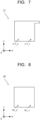
- FIG. 7 is a schematic view illustrating an example structure of the anode current collector 17.
- FIG. 7 illustrates an X-Y plane view.
- the anode current collector 17 has, for example, an opening 171.
- the opening 171 is provided through the anode current collector 17 in the Z-axis direction, and examples of the opening 171 include a through hole such as a via.
- the anode current collector 17 has a plurality of the openings 171. One of the openings 171 allows the cathode fluid to flow therethrough. Another of the openings 171 allows the anode fluid to flow therethrough.
- FIG. 7 illustrates an X-Y plane view.
- the anode current collector 17 has, for example, an opening 171.
- the opening 171 is provided through the anode current collector 17 in the Z-axis direction, and examples of the opening 171 include a through hole such as a via.
- the anode current collector 17 has a plurality of the openings 171.
- the opening 171_1 is connected, for example, to the opening 151_1.
- the opening 171_2 is connected, for example, to the opening 151_2.
- the opening 171_1 allows the cathode fluid to flow therethrough.
- the opening 171_2 allows the anode fluid to flow therethrogh.
- FIG. 8 is a schematic view illustrating an example structure of the insulating layer 18.
- FIG. 8 illustrates an X-Y plane view.
- the insulating layer 18 has, for example, an opening 181.
- the opening 181 is provided through the insulating layer 18 in the Z-axis direction, examples of the opening 18 include a through hole such as a via.
- the insulating layer 18 has a plurality of the openings 181.
- One of the openings 181 allows the cathode fluid to flow therethrough.
- Another of the openings 181 allows the anode fluid to flow therethorugh.
- FIG. 8 illustrates an opening 181_1 and an opening 181_2 as the openings 181, but the number of the openings 181 only needs to be two or more and is not limited to the number illustrated in FIG.
- the opening 181_1 is connected, for example, to the opening 171_1.
- the opening 181_2 is connected, for example, to the opening 171_2.
- the opening 181_1 allows the cathode fluid to flow therethrough.
- the opening 181_2 allows the anode fluid to flow therethrough.
- positions of the openings 131, the openings 141, the openings 151, the openings 161, the openings 171, and the openings 181 may be different between an electrolysis cell 10_2n-1 (n is a natural number) at an odd stage such as the electrolysis cell 10_1 and an electrolysis cell 10_2n (n is a natural number) at an even stage such as the electrolysis cell 10_2.
- positions of the opening 131_1 and the opening 131_2, positions of the opening 141_1 and the opening 141_2, positions of the opening 151_1 and the opening 151_2, positions of the opening 161_1 and the opening 161_2, positions of the opening 171_1 and the opening 171_2, and positions of the opening 181_1 and the opening 181_2 each may have a symmetrical relationship between the electrolysis cell 10_2n-1 (n is a natural number) at the odd stage and the electrolysis cell 10_2n (n is a natural number) at the even stage.
- positions of the opening 131_1 and the opening 131_2, positions of the opening 141_1 and the opening 141_2, positions of the opening 151_1 and the opening 151_2, positions of the opening 161_1 and the opening 161_2, positions of the opening 171_1 and the opening 171_2, and positions of the opening 181_1 and the opening 181_2 each may have an asymmetrical relationship between the electrolysis cell 10_2n-1 (n is a natural number) at the odd stage and the electrolysis cell 10_2n (n is a natural number) at the even stage.
- the packing may be provided with a plurality of openings, and through which the cathode fluid and the anode fluid may be allowed to pass.
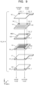
- FIG. 9 and FIG. 10 are schematic views for explaining the flow of the cathode fluid and the flow of the anode fluid in the electrolysis cells 10. Arrows of solid lines illustrated in FIG. 9 and FIG. 10 indicate the flow of the cathode fluid. Arrows of dotted lines in FIG. 9 and FIG. 10 indicate the flow of the anode fluid.
- the cathode fluid passes through the opening 161_1, passes through the opening 141_1, moves from one end to the other end of the cathode flow path 140, passes through the opening 131_1, passes through the opening 151_1, passes through the opening 171_1, and passes through the opening 181_1, and thereby can move to the electrolysis cell 10 at a next stage.
- the anode fluid passes through the opening 161_2, passes through the opening 141_2, passes through the opening 131_2, moves from one end to the other end of the anode flow path 150, passes through the opening 151_2, passes through the opening 171_2, and passes through the opening 181_2, and thereby can move to the electrolysis cell 10 at the next stage.
- the cathode fluid passes through the opening 161_1, passes through the opening 141_1, moves from one end to the other end of the cathode flow path 140, passes through the opening 131_1, passes through the opening 151_1, passes through the opening 171_1, and passes through the opening 181_1, and thereby can move to an electrolysis cell 10 at a next stage.
- the anode fluid passes through the opening 161_2, passes through the opening 141_2, passes through the opening 131_2, moves from one end to the other end of the anode flow path 150, passes through the opening 151_2, passes through the opening 171_2, and passes through the opening 181_2, and thereby can move to the electrolysis cell 10 at the next stage.
- H + produced at the anode 12 moves through the electrolytic solution existing in the anode flow path 150 and the diaphragm 13 and reaches the vicinity of the cathode 11. Electrons (e - ) based on the current supplied from the power supply 40 to the cathode 11 and H + moved to the vicinity of the cathode 11 cause a reduction reaction of carbon dioxide. Specifically, carbon dioxide supplied from the cathode flow path 140 to the cathode 11 is reduced to produce carbon monoxide as expressed by Formula (2) below. Further, hydrogen ions receive electrons to produce hydrogen as in Formula (3) below. In this event, hydrogen may be produced at the same time with carbon monoxide. CO 2 + 2H + + 2e - ⁇ CO + H 2 O ... (2) 2H + + 2e - ⁇ H 2 ... (3)
- hydroxide ions (OH - ) produced by the reactions diffuse in the vicinity of the anode 12, whereby the hydroxide ions (OH - ) are oxidized to produce oxygen (O 2 ) as in Formula (6) below.
- O 2 oxygen
- the electrolysis cell 10 is not specialized only for the reduction of carbon dioxide, but can produce, for example, carbon monoxide and hydrogen at 1:2 and also manufacture a reduction product and hydrogen at an arbitrary ratio such as manufacturing methanol by a chemical reaction thereafter.
- the percentage of hydrogen is at least 1 or more, and preferably 1.5 or more in terms of economy and environment.
- hydrogen peroxide (H 2 O 2 ) may be produced as an intermediate product or a product.
- Conceivable oxygen reduction reactions are two-electron reduction and four-electron reduction, and can occur in any of acidic and alkaline environments.
- the electrolysis cell 10 is not specialized only for the reduction of carbon dioxide, but if impurity gases of oxygen and nitrogen are mixed, the electrolysis cell 10 can also reduce them.
- the cathode 11 can reduce nitrogen to produce ammonia.
- the configuration of the electrolysis device 1 can be appropriately used.
- the impurity gas of the cathode fluid is not nitrogen.
- the cathode fluid contains gas of the reducible material such as carbon dioxide or nitrogen and gas of an impurity such as oxygen
- gas of the reducible material such as carbon dioxide or nitrogen
- an impurity such as oxygen
- the cathode fluid is supplied from the cathode supply source 20 to the cell structure 100 and the electrolysis cell 10 reduces the reducible material to produce the reduction product
- current is consumed for the reduction of the impurity gas and therefore current is accordingly wastefully consumed.
- the current for reducing the reducible material accordingly decreases, the amount of carbon dioxide to be reduced decreases, and the Faraday efficiency of the reduction product such as the carbon compound and ammonia may decrease.
- the cathode fluid, the anode fluid, and the power supply current are supplied to flow through the cell stack in series, and therefore it is difficult to control the current supply amount of the electrolysis cell at the first stage where the reduction of the impurity gas mainly occurs. Further, to achieve the high electrolysis efficiency of the electrolysis device, it is necessary to make the electrolysis device operable with low power consumption.
- the electrolysis device in the arrangement can supply a first power supply current to the electrolysis cells 10 in a first group including the electrolysis cell 10 at the first stage, and supply a second power supply current to the electrolysis cells 10 in a second group including at least one of the electrolysis cells 10 at the next and subsequent stages.
- a plurality of the electrolysis cells 10 are connected in parallel to the power supply 40, and thereby current can be independently supplied to each of the electrolysis cells 10.
- the first power supply current may be supplied to the electrolysis cells 10 in the first group including the electrolysis cells 10 at the first stage to an X stage (X is a natural number of 2 or more), and the second power supply current may be supplied to the electrolysis cells 10 in the second group including at least one of the electrolysis cells 10 at an X+1 and subsequent stages.
- FIG. 11 is a schematic view illustrating an appearance in which an impurity such as oxygen and a reducible material such as carbon dioxide in the cathode fluid flow in series through the electrolysis cells 10.
- FIG. 12 is a chart illustrating examples of graphs indicating the relation among a current density flowing through the electrolysis cell 10, a cell voltage, and a Faraday efficiency.
- a curve of a solid line illustrated in FIG. 12 indicates the relation between a cell voltage of the electrolysis cell 10 supplied with a mixed gas containing gas of carbon dioxide and gas of oxygen and a current density of current flowing through the electrolysis cell 10.
- a curve of a one-dotted chain line illustrated in FIG. 12 indicates the relation between a Faraday efficiency of carbon monoxide of the electrolysis cell 10 supplied with a single gas of carbon dioxide and a current density of current flowing through the electrolysis cell 10.
- a curve of a two-dotted chain line illustrated in FIG. 12 indicates the relation between a Faraday efficiency of carbon monoxide of the electrolysis cell 10 supplied with a mixed gas containing a carbon dioxide gas and an oxygen gas and a current density of current flowing through the electrolysis cell 10.
- the reduction of oxygen is mainly and preferentially performed in a range (range A in FIG. 12 ) of a low current density of 100 mA/cm 2 or less, current is mainly consumed for the production of water or the like by the oxygen reduction, so that the production of carbon monoxide by the reduction of carbon dioxide does not proceed.
- a range (the range B in FIG. 12 ) of a high current density of 200 mA/cm 2 or more the reduction of carbon dioxide is mainly and preferentially performed and current is mainly consumed for the production of carbon monoxide by the reduction of carbon dioxide.
- the first power supply current is supplied so that the current flowing through the electrolysis cell 10 at the first stage (electrolysis cell 10_1) has a low current density.
- the current density at this time is, for example, 1 mA/cm 2 or more and 150 mA/cm 2 or less. This allows the reduction of oxygen to be preferentially performed in the electrolysis cell 10 at the first stage. As a result, almost all of the impurities in the cathode fluid are reduced in the electrolysis cell 10 at the first stage, so that the composition of the cathode fluid flowing through the electrolysis cells 10 at the next and subsequent stage is only gas of mainly the reducible material.
- the area of the electrolysis cell 10 at the first stage and the area of the electrolysis cell 10 at the next or subsequent stage are the same, but the areas of the electrolysis cells 10 do not always need to be the same.
- the area of the electrolysis cell 10 includes, for example, the area of an overlapping portion of the cathode 11 and the cathode flow path 140, the area of an overlapping portion of the anode 12 and the anode flow path 150, and so on.
- the second power supply current is supplied so that the current flowing through the electrolysis cells 10 at the next and subsequent stages has a high current density.
- the current density at this time is, for example, 150 mA/cm 2 or more.
- the upper limit of the current density is not particularly limited but is, for example, 1000 mA/cm 2 or less.
- the composition of the cathode fluid to be supplied to the electrolysis cells 10 at the next and subsequent stages can be composed of almost only gas of the reducible material, so that the electrolysis cell 10 where the current is consumed for the reduction of impurities can be limited to the electrolysis cell 10 at the first stage, thereby making it possible to suppress the unnecessary current consumption in the electrolytic reaction such as the reduction reaction of impurities.
- the impurity gas such as oxygen is sometimes supplied also to the electrolysis cells 10 at the second and subsequent stages.
- the power supply current can be supplied from the power supply 40 so that the current density of the current flowing through each of the electrolysis cells 10 in the second group including at least one of the electrolysis cells 10 at the next and subsequent stages is higher than the current density of the current flowing through each of the electrolysis cells 10 in the first group including the electrolysis cell 10_1 at the first stage and at least one of the electrolysis cells 10 at the second and subsequent stages.
- the reduction potential of a carbon dioxide gas is higher than the reduction potential of an oxygen gas as illustrated in FIG. 12 .
- FIG. 13 is a schematic view illustrating another example of the electrolysis device in the arrangement.
- FIG. 13 illustrates another configuration example of the electrolysis device 1.
- the electrolysis device 1 may share one cathode current collector 16 and one anode current collector 17 among a plurality of the stacked electrolysis cells 10 as illustrated in FIG. 13.
- FIG. 13 illustrates an example including an electrolysis cell 10_2 and an electrolysis cell 10_3 between the one cathode current collector 16 and the one anode current collector 17 in which the anode flow path plate 15 in the electrolysis cell 10_2 is electrically connected to the cathode flow path plate 14 in the electrolysis cell 10_3.
- the above configuration can decrease the numbers of the cathode current collectors 16 and the anode current collectors 17 and thereby can suppress the manufacturing cost and thickness of the cell structure 100.
- FIG. 14 is a schematic view illustrating another example of the electrolysis device in the arrangement.
- FIG. 14 illustrates another configuration example of the electrolysis device 1.
- the electrolysis device 1 may have a power supply 41 and a power supply 42 as illustrated in FIG. 14 .
- the power supply 41 is electrically connected to the electrolysis cells 10 in the first group including the electrolysis cell 10 at the first stage.
- the power supply 41 can supply the first power supply current to the electrolysis cell 10 at the first stage.
- the explanation of the power supply 40 can be appropriately used.
- the power supply 42 is electrically connected to the electrolysis cells 10 in the second group including at least one of the electrolysis cells 10 at stages next and subsequent to the electrolysis cells 10 in the first group.
- the power supply 42 can supply the second power supply current to the electrolysis cell 10 at the next and subsequent stages.
- the explanation of the power supply 40 can be appropriately used.
- the values of the first power supply current and the second power supply current are adjusted by the power supply 41 and the power supply 42 so that when the area of the electrolysis cells 10 in the first group and the area of the electrolysis cells 10 in the second group are the same, the current density of the current flowing through the electrolysis cells 10 in the second group is higher than the current density of the current flowing through the electrolysis cells 10 in the first group.
- the above configuration can individually set the first power supply current and the second power supply current, for example, to have optimum current densities in accordance with the respective cell voltages of the electrolysis cells 10 in the first group and the electrolysis cells 10 in the second group, and supply them.
- the optimum current densities can be adjusted by providing a resistor between the electrolysis cells 10 in the first group and the electrolysis cells 10 in the second group or connecting a current monitor to each of the electrolysis cells 10.
- the current may be supplied while controlling the cell voltage of each electrolysis cell 10.
- the reduction product may be selectively changed by controlling the voltage or current of the electrolysis cells 10 in the second group.
- the area of the electrolysis cells 10 in the first group and the area of the electrolysis cells 10 in the second group are the same, but the areas of a plurality of electrolysis cells do always need to be the same.
- the values of the current density of the first power supply current and the current density of the second power supply current are adjusted by the power supply 41 and the power supply 42 so that the current density of current flowing through the electrolysis cells 10 in the second group is higher than the current density of current flowing through the electrolysis cells 10 in the first group.
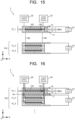
- FIG. 15 is a schematic view illustrating another example of the electrolysis device in the arrangement.
- FIG. 15 illustrates another configuration example of the electrolysis device 1.
- the electrolysis device 1 may have a power supply 41, a power supply 42, a pipe 19a for separating the electrolysis cells 10 in the first group and the electrolysis cells 10 in the second group and supplying the cathode fluid from the electrolysis cells 10 in the first group to the electrolysis cells 10 in the second group, and a pipe 19b for supplying the anode fluid from the electrolysis cells 10 in the first group to the electrolysis cells 10 in the second group.
- the pipe 19a connects the cathode flow path 140 of the electrolysis cell 10 at the final stage in the first group and the cathode flow path 140 of the electrolysis cell 10 at the initial stage in the second group.
- the pipe 19b connects the anode flow path 150 of the electrolysis cell 10 at the final stage in the first group and the anode flow path 150 of the electrolysis cell 10 at the initial stage in the second group.
- the pipe 19a and the pipe 19b can be formed using, for example, a metal material or an insulating material. The above configuration can keep a distance between the electrolysis cells 10 in the first group and the electrolysis cells 10 in the second group. This can efficiently utilize, for example, even a small installation space.
- FIG. 16 is a schematic view illustrating another example of the electrolysis device in the arrangement.
- FIG. 16 illustrates another configuration example of the electrolysis device 1.
- the electrolysis device 1 may have a power supply 41 and a power supply 42, supply the cathode fluid from the cathode supply source 20 to flow in parallel through the electrolysis cells 10, and supply the anode fluid from the anode supply source 30 to flow in parallel through the stacked electrolysis cells 10.
- the cathode flow paths 140 of the electrolysis cells 10 in the first group and the cathode flow paths 140 of the electrolysis cells 10 in the second group may be connected, for example, in parallel.
- the anode flow paths 150 of the electrolysis cells 10 in the first group and the anode flow paths 150 of the electrolysis cells 10 in the second group may be connected, for example, in parallel.
- the above configuration can individually set optimum current and gas composition and its gas flow rate in accordance with the respective cell voltages of the electrolysis cells 10 in the first group and the electrolysis cells 10 in the second group, and make them flow.
- the optimum current density can be adjusted by providing a resistor between the electrolysis cells 10 in the first group and the electrolysis cells 10 in the second group or connecting a current monitor to each of the electrolysis cells 10.
- the current may be supplied while controlling the cell voltage of each electrolysis cell 10.
- the reduction product may be selectively changed by controlling the voltage or current of the electrolysis cells 10 in the second group.
- the electrolysis cells 10 in the first group reduce nitrogen to produce ammonia
- the electrolysis cells 10 in the second group reduce the reducible material such as carbon dioxide to produce a reduction product such as a carbon compound.
- the cathodes 11 in the electrolysis cells 10 in the first group may have a first catalyst and the cathodes 11 in the electrolysis cells 10 in the second group may have a second catalyst.
- the first catalyst is different from the second catalyst.
- Examples of the first catalyst include platinum and its alloy.
- Examples of the second catalyst include gold. The selection of an optimum catalyst according to a main product for each electrolysis cell 10 can improve the electrolysis efficiency of the electrolysis device.
- the electrolysis device 1 may be employed, for example, for an electrolysis system.
- the electrolysis system may further include a control device.
- the control device can control, for example, the power supply voltages or the power supply currents from the power supply 40. Further, the control device can control, for example, the flow rate of the cathode fluid from the cathode supply source 20. Further, the control device can control, for example, the flow rate of the anode fluid from the anode supply source 30.
- the control device has, for example, hardware having an arithmetic unit such as a processor. Each operation may be held as an operating program on a computer-readable recording medium such as a memory and each operation may be executed by appropriately reading the operation program stored on the recording medium by the hardware.
Landscapes
- Chemical & Material Sciences (AREA)
- Organic Chemistry (AREA)
- Engineering & Computer Science (AREA)
- Chemical Kinetics & Catalysis (AREA)
- Electrochemistry (AREA)
- Materials Engineering (AREA)
- Metallurgy (AREA)
- Inorganic Chemistry (AREA)
- Automation & Control Theory (AREA)
- Electrolytic Production Of Non-Metals, Compounds, Apparatuses Therefor (AREA)
Abstract
Description
- Arrangements relate to an electrolysis device and an electrolysis system.
- In recent years, renewable energies should be exploited by not only being converted into electric energy as solar power generation but also being converted into storable and conveyable resources, in view of both an energy problem and an environment problem. This request has developed research and development of an artificial photosynthesis technology of generating a chemical substance using sunlight as in photosynthesis by plants. This technology may enable converting renewable energy into storable fuels, and may enable producing a chemical substance as an industrial raw material to create valuables.
- Examples of an apparatus, which produces the chemical substance using the renewable energy of solar power generation, include an electrolysis device (electrochemical reaction device) such as a carbon dioxide electrolysis device having a cathode and a anode, the cathode reducing carbon dioxide (CO2) generated from a power station or a waste treatment plant, and the anode oxidizing water (H2O). The cathode can reduce carbon dioxide to produce a carbon compound such as carbon monoxide (CO), for example. When the electrolysis device is composed by forming a cell (also referred to as an electrolysis cell), it is considered effective to compose the electrolysis device by forming a cell similar to a cell of a fuel cell such as Polymer Electric Fuel Cell (PEFC), for example. The carbon dioxide electrolysis device can directly supply carbon dioxide to a catalyst layer of the cathode to speedily reduce the carbon dioxide. Further, the carbon dioxide electrolysis device can have a stack structure, which is formed by stacking electrolysis cells, to prevent an increase of the area of the carbon dioxide electrolysis device and to efficiently reduce the carbon dioxide.
-
- Reference 1:
US 2011/025643 A1 - Reference 2:
US 7147953 B2 - Reference 3:
JP 2022-42280 A - Reference 4: ACS Energy Lett. 2019, 4, 1770-1777
-
-
FIG. 1 is a schematic view illustrating a configuration example of an electrolysis device in an arrangement. -
FIG. 2 is a perspective schematic view illustrating an example structure of acell structure 100. -
FIG. 3 is a schematic view illustrating an example structure of a membrane electrode assembly MEA. -
FIG. 4 is a schematic view illustrating an example structure of a cathodeflow path plate 14. -
FIG. 5 is a schematic view illustrating an example structure of an anodeflow path plate 15. -
FIG. 6 is a schematic view illustrating an example structure of a cathodecurrent collector 16. -
FIG. 7 is a schematic view illustrating an example structure of an anodecurrent collector 17. -
FIG. 8 is a schematic view illustrating an example structure of aninsulating layer 18. -
FIG. 9 is a schematic view for explaining the flow of a cathode fluid and the flow of an anode fluid in thecell structure 100. -
FIG. 10 is a perspective schematic view illustrating an example structure of thecell structure 100. -
FIG. 11 is a schematic view illustrating an appearance in which an impurity and a reducible material in the cathode fluid flow in series throughelectrolysis cells 10. -
FIG. 12 is a chart illustrating examples of graphs indicating the relation among a current density flowing through theelectrolysis cell 10, a cell voltage, and a Faraday efficiency. -
FIG. 13 is a schematic view illustrating another example of the electrolysis device in the arrangement. -
FIG. 14 is a schematic view illustrating another example of the electrolysis device in the arrangement. -
FIG. 15 is a schematic view illustrating another example of the electrolysis device in the arrangement. -
FIG. 16 is a schematic view illustrating another example of the electrolysis device in the arrangement. - An electrolysis device according to an arrangement includes: a first electrolysis cell configured to reduce a reducible material and to oxidize an oxidizable material; a second electrolysis cell configured to reduce the reducible material and to oxidize the oxidizable material; a first supply source configured to supply a first fluid to the first electrolysis cell and the second electrolysis cell, the first fluid containing a gas of the reducible material; a second supply source configured to supply a second fluid to the first electrolysis cell and the second electrolysis cell, the second fluid containing a liquid of the oxidizable material; and at least one power supply configured to supply a first power supply current to the first electrolysis cell and to supply a second power supply current to the second electrolysis cell. The at least one power supply is configured to set a value of the first power supply current and a value of the second power supply current so that a current density of current flowing through the second electrolysis cell when reducing the reducible material is higher than a current density of current flowing through the first electrolysis cell when reducing the reducible material.
- Electrolysis devices in arrangements will be explained below with reference to the drawings. In the arrangements explained below, substantially the same components are denoted by the same reference signs and the explanation thereof will be partially omitted in some cases. The drawings are schematic, in which the relationship between the thickness and planar dimensions, a thickness ratio among the components, and so on may be different from actual ones.
- In this specification, "connecting" includes not only directly connecting but also indirectly connecting unless otherwise specified. Further, in this specification, "connecting" includes not only physically connecting but also electrically connecting unless otherwise specified.
-
FIG. 1 is a schematic view illustrating a configuration example of an electrolysis device in an arrangement.FIG. 1 illustrates a configuration example of anelectrolysis device 1. Theelectrolysis device 1 includes anelectrolysis cell 10 which performs an electrolytic reaction, acathode supply source 20 which supplies cathode a fluid, ananode supply source 30 which supplies an anode fluid, and apower supply 40 which feeds power to theelectrolysis cell 10.FIG. 1 illustrates an X-axis, a Y-axis, and a Z-axis. The X-axis, the Y-axis, and the Z-axis vertically cross one another. The Z-axis is along a thickness direction of theelectrolysis cell 10.FIG. 1 illustrates a part of an X-Z cross section including the X-axis and the Z-axis. - The
electrolysis cell 10 has a cathode 11, ananode 12, a diaphragm (separator) 13, a cathodeflow path plate 14 having acathode flow path 140, an anodeflow path plate 15 having ananode flow path 150, a cathodecurrent collector 16, and an anodecurrent collector 17. The cathode 11, theanode 12, and thediaphragm 13 may be stacked to form a membrane electrode assembly MEA. The order of stacking the components of theelectrolysis cell 10 is not limited to that inFIG. 1 , but they may be stacked, for example, in an order reverse to the order illustrated inFIG. 1 . - The
electrolysis device 1 has a plurality of theelectrolysis cells 10. Theelectrolysis cells 10 are stacked, for example, with aninsulating layer 18 intervening therebetween to form acell structure 100 such as a cell stack.FIG. 2 is a perspective schematic view illustrating an example structure of thecell structure 100. Thecell structure 100 further has aninsulating layer 18 between two stackedelectrolysis cells 10. The stackedelectrolysis cells 10 may be sandwiched between a pair of supporting plates and further fastened with bolts or the like.FIG. 1 and FIG. 2 illustrate electrolysis cells 10_1, 10_2, 10_3 as theelectrolysis cells 10, but the number ofelectrolysis cells 10 only needs to be two or more and is not limited to the number illustrated inFIG. 1 and FIG. 2 . - The cathode 11 is an electrode (a reduction electrode) for causing, for example, a reduction reaction of at least one reducible material (at least one substance to be reduced) to produce a reduction product. The at least one reducible material includes, for example, carbon dioxide or nitrogen. The cathode 11 is in contact with the
diaphragm 13. The cathode 11 is an electrode (a reduction electrode) for causing a reduction reaction of the reducible material to produce the reduction product. Examples of the reducible material include carbon dioxide, nitrogen, hydrogen, oxygen, reduction product, and so on. Examples of the reduction product include carbon compound, ammonia, and so on. Examples of the carbon compound include carbon monoxide (CO), methane (CH4), ethane (C2H6), and so on. The reduction reaction at the cathode 11 may include a side reaction of causing a reduction reaction of water to produce hydrogen (H2). Further, the reduction reaction at the cathode 11 may include a side reaction of causing a reduction reaction of carbon dioxide and a reduction reaction of oxygen to produce water (H2O). - The cathode 11 is supplied with the anode fluid and ions from the
diaphragm 13 and is supplied with the cathode fluid from thecathode flow path 140. The cathode 11 may have a gas diffusion layer and a cathode catalyst layer provided on the gas diffusion layer. The cathode 11 may further have a porous layer denser than the gas diffusion layer, between the gas diffusion layer and the cathode catalyst layer. The gas diffusion layer is arranged adjacent to thecathode flow path 140, and the cathode catalyst layer is arranged adjacent to thediaphragm 13. The cathode catalyst layer may extend into the gas diffusion layer. The cathode catalyst layer preferably has a catalyst nanoparticle, a catalyst nanostructure, or the like. The gas diffusion layer is composed of, for example, carbon paper, carbon cloth, or the like, and may have been subjected to a water repellent treatment. The porous layer is composed of a porous member smaller in pore size than the carbon paper or carbon cloth. - An appropriate water repellent treatment to the gas diffusion layer allows a carbon dioxide gas to reach the cathode catalyst layer mainly by gas diffusion. The reduction reaction of the carbon dioxide and the reduction reaction of a carbon compound produced thereby occur near the boundary between the gas diffusion layer and the cathode catalyst layer or near the cathode catalyst layer intruding into the gas diffusion layer.
- The cathode catalyst layer preferably contains a catalyst material (cathode catalyst material) capable of decreasing an overvoltage of the reduction reaction. Examples of the material include metals such as gold (Au), silver (Ag), copper (Cu), platinum (Pt), palladium (Pd), nickel (Ni), cobalt (Co), iron (Fe), manganese (Mn), titanium (Ti), cadmium (Cd), zinc (Zn), indium (In), gallium (Ga), lead (Pb), and tin (Sn), metal materials such as alloys and intermetallic compounds containing at least one of the metals, carbon materials such as carbon (C), graphene, CNT (carbon nanotube), fullerene, and ketjen black, and metal complexes such as a Ru complex and a Re complex. To the cathode catalyst layer, various shapes such as a plate shape, a mesh shape, a wire shape, a particle shape, a porous shape, a thin film shape, or an island shape can be applied.
- The cathode catalyst material constituting the cathode catalyst layer preferably has a nanoparticle of the above metal material, a nanostructure of the metal material, a nanowire of the metal material, or a composite in which the nanoparticle of the metal material is supported by a carbon material such as carbon particle, carbon nanotube, or graphene. The use of the catalyst nanoparticle, the catalyst nanostructure, a catalyst nanowire, a catalyst nanosupport structure, or the like, as the cathode catalyst material can enhance the reaction efficiency of the reduction reaction of carbon dioxide at the cathode 11.
- The
anode 12 is provided between thediaphragm 13 and theanode flow path 150 and is in contact with them. Theanode 12 is an electrode (an oxidization electrode) for oxidizing water (H2O) in an anode solution contained in the anode fluid to produce oxygen (O2) and hydrogen ions (H+) or an electrode for oxidizing hydroxide ions (OH-) produced by the reduction reaction of carbon dioxide at the cathode 11 to produce oxygen and water. - The
anode 12 preferably contains a catalyst material (a anode catalyst material) capable of decreasing an overvoltage of the oxidation reaction. Examples of the catalyst material include metals such as platinum (Pt), palladium (Pd), and nickel (Ni), alloys and intermetallic compounds containing those metals, binary metal oxides such as manganese oxide (Mn-O), iridium oxide (Ir-O), nickel oxide (Ni-O), cobalt oxide (Co-O), iron oxide (Fe-O), tin oxide (Sn-O), indium oxide (In-O), ruthenium oxide (Ru-O), lithium oxide (Li-O), and lanthanum oxide (La-O), ternary metal oxides such as Ni-Co-O, Ni-Fe-O, La-Co-O, Ni-La-O, and Sr-Fe-O, quaternary metal oxides such as Pb-Ru-Ir-O and La-Sr-Co-O, and metal complexes such as a Ru complex and a Fe complex. - The
anode 12 includes a base material having a structure capable of moving liquid and ions between thediaphragm 13 and theanode flow path 150, for example, a porous structure such as a mesh material, a punched material, a porous member, or a metal fiber sintered compact. The base material may be composed of a metal such as titanium (Ti), nickel (Ni), or iron (Fe) or a metal material such as an alloy (for example SUS) containing at least one of the metals, or may be composed of the aforementioned anode catalyst material. In the case of using an oxide as the anode catalyst material, it is preferable to bond or stack the anode catalyst material on the surface of the base material composed of the above metal material to form a catalyst layer. The anode catalyst material preferably has a nanoparticle, a nanostructure, a nanowire, or the like in order to enhance the oxidation reaction. The nanostructure is a structure obtained by forming nanoscale irregularities on the surface of the catalyst material. The oxidation catalyst does not always need to be provided at theanode 12. An oxidation catalyst layer provided other than theanode 12 may be electrically connected to theanode 12. - The
diaphragm 13 is provided between the cathode 11 and theanode 12. Thediaphragm 13 is arranged to separate the cathode 11 and theanode 12 from each other. Thediaphragm 13 includes an ion exchange membrane capable of moving ions between the cathode 11 and theanode 12 and separating the cathode 11 and theanode 12 from each other. Examples of the usable ion exchange membrane include a cation exchange membrane such as Nafion or Flemion, or an anion exchange membrane such as Neosepta, Selemion, or Sustainion. In the case of assuming the movement of mainly OH- by using an alkaline solution for the electrolytic solution, thediaphragm 13 is preferably composed of an anion exchange membrane. The ion exchange membrane may be composed using a film using hydrocarbon as a basic structure or a film having an amine group. However, other than the ion exchange membrane, a salt bridge, a glass filter, a porous polymer membrane, a porous insulating material, or the like, as long as it is a material capable of moving ions between the cathode 11 and theanode 12, may be applied to thediaphragm 13. However, if passage of gas occurs between the cathode 11 and theanode 12, a circular reaction due to reoxidation of the reduction product may occur. Therefore, it is preferable that there is less exchange of gas between the cathode 11 and theanode 12. Therefore, it is necessary to take care when using a thin film of a porous member as thediaphragm 13. - The cathode
flow path plate 14 has thecathode flow path 140. Thecathode flow path 140 faces on the cathode 11. Thecathode flow path 140 allows the cathode fluid to be supplied to the cathode 11 and containing the reducible material to flow therethrough. The cathode fluid may contain water vapor by humidification. The reduction product is mainly discharged from thecathode flow path 140 while being contained in the cathode fluid. The reduction product is different depending on the type of the reduction catalyst or the like. Together with the gas products, vapor or moisture obtained by dew condensation of vapor contained in the humidified carbon dioxide gas is drained from thecathode flow path 140. - The reduction product is different also depending on the composition of the cathode fluid. In the case where the cathode fluid contains a carbon dioxide gas or a humidified carbon dioxide gas, a carbon monoxide gas and a reduction product such as hydrogen as a by-product are mainly produced. In the case where the cathode fluid contains a nitrogen gas, a reduction product such as ammonia is mainly produced. In the case where the cathode fluid contains an impurity gas such as oxygen, oxygen is reduced to produce water as a reduction product.
- The
cathode flow path 140 is provided on the surface of the cathodeflow path plate 14. The cathodeflow path plate 14 has a groove (recessed portion) which forms thecathode flow path 140 on the surface. The cathodeflow path plate 14 is preferably formed using a material low in chemical reactivity and high in conductivity. Examples of the material include metal materials such as Ti and SUS, carbon, and the like. Examples of the material of the flow path plate include a material low in chemical reactivity and having no conductivity. Examples of the material include insulating resin materials such as an acrylic resin, polyether ether ketone (PEEK), and a fluorocarbon resin. The cathodeflow path plate 14 has a not-illustrated screw hole for fastening. Further, before and after cathodeflow path plates 14, not-illustrated packing may be sandwiched as necessary. Thecathode flow path 140 may be provided in the cathodecurrent collector 16. - The
cathode flow path 140 has an inlet and an outlet, is supplied with the cathode fluid from thecathode supply source 20 through the inlet, and discharges an unreacted reducible material and the reduction product through the outlet. The cathode fluid flows through the inside of thecathode flow path 140 in a manner to be in contact with the cathode 11. The cathode fluid discharged from thecathode flow path 140 may contain the unreacted reducible material, the reduction product, and so on. - The
cathode flow path 140 may have a land in contact with the cathode 11 for electrical connection with the cathode 11. The shape of thecathode flow path 140 is not particularly limited, and can be a serpentine structure obtained by folding an elongated flow path or the like. Thus, it is preferable that the cathode fluid uniformly flows on the surface of the cathode 11, thereby allowing a uniform reaction to be performed at the cathode 11. - The cathode fluid may be supplied in a dry state. In the case where the cathode fluid contains a carbon dioxide gas, a carbon dioxide concentration of the cathode fluid to be supplied from the
cathode supply source 20 to thecathode flow path 140 does not have to be 100%. It is also possible to use fluid containing the carbon dioxide gas discharged from various facilities, as the cathode fluid. In this case, the cathode fluid may contain an impurity gas. Assuming that a first gas contained in the cathode fluid is the carbon dioxide gas, a second gas is a substance different from carbon dioxide, such as oxygen or nitrogen. The concentration of the second gas is preferably lower than the concentration of the first gas and is, for example, 1 ppm or higher and 100000 ppm or lower. - The cathode
flow path plate 14 is mainly formed of one member, but may be formed of a plurality of different members and constructed by stacking them. Further, a surface treatment may be performed partially or entirely on the cathodeflow path plate 14 to add a hydrophilic or water repellent function to the cathodeflow path plate 14. - The anode
flow path plate 15 has theanode flow path 150. Theanode flow path 150 faces on theanode 12. Theanode flow path 150 allows the anode fluid to be supplied to theanode 12 to flow therethrough. The anode fluid contains liquid such as the anode solution. - The anode solution preferably contains at least water (H2O). For example, in the case where the reducible material is carbon dioxide, carbon dioxide is supplied from the
cathode flow path 140, so that the anode solution may or may not contain carbon dioxide. - As the anode solution, an aqueous solution (electrolytic solution) containing metal ions can be used. Examples of the aqueous solution include aqueous solutions containing phosphate ion (PO4 2-), borate ion (BO3 3-), sodium ion (Na+), potassium ion (K+), calcium ion (Ca2+), lithium ion (Li+), cesium ion (Cs+), magnesium ion (Mg2+), chloride ion (Cl-), hydrogen carbonate ion (HCO3 -), and so on. In addition, aqueous solutions containing lithium hydrogen carbonate (LiHCO3), sodium hydrogen carbonate (NaHCO3), potassium hydrogen carbonate (KHCO3), cesium hydrogen carbonate (CsHCO3), phosphoric acid, boric acid, and so on may be used.
- The
anode flow path 150 is provided on the surface of the anodeflow path plate 15. The anodeflow path plate 15 is for supplying the anode fluid to theanode 12, and has a groove (recessed portion) which forms theanode flow path 150 on the surface. The anodeflow path plate 15 is preferably formed using a material low in chemical reactivity and high in conductivity. Examples of the material include metal materials such as Ti and SUS, carbon, and so on. Theanode flow path 150 may be provided at the anodecurrent collector 17. Further, examples of the material of the anodeflow path plate 15 include a material low in chemical reactivity and having no conductivity. Examples of the material include insulating resin materials such as an acrylic resin, polyether ether ketone (PEEK), and a fluorocarbon resin. The anodeflow path plate 15 has a not-illustrated screw hole for fastening. - The anode
flow path plate 15 is mainly formed of one member, but may be formed of a plurality of different members and constructed by stacking them. Further, a surface treatment may be performed partially or entirely on the anodeflow path plate 15 to add a hydrophilic or water repellent function to the anodeflow path plate 15. - The
anode flow path 150 has an inlet and an outlet, is supplied with the anode fluid from theanode supply source 30 through the inlet, and discharges the anode fluid through the outlet. The anode fluid flows through the inside of theanode flow path 150 in a manner to be in contact with theanode 12. The anode fluid discharged from theanode flow path 150 may contain an unreacted oxidizable material, an oxidation product, and so on. - The
anode flow path 150 may have a land in contact with theanode 12 for electrical connection with theanode 12. The shape of theanode flow path 150 is not particularly limited, and can be a serpentine structure obtained by folding an elongated flow path or the like. Thus, it is preferable that the anode fluid uniformly flows on the surface of theanode 12, thereby allowing a uniform reaction to be performed at theanode 12. - The cathode
current collector 16 is electrically connected to the cathode 11. The cathodecurrent collector 16 is in contact with a surface of the cathodeflow path plate 14 across the cathodeflow path plate 14 from thecathode flow path 140. The cathodecurrent collector 16 preferably contains a material low in chemical reactivity and high in conductivity. Examples of the material include metal materials such as Ti and SUS, carbon, and so on. - The anode
current collector 17 is electrically connected to theanode 12. The anodecurrent collector 17 is in contact with a surface of the anodeflow path plate 15 across the anodeflow path plate 15 from theanode flow path 150. The anodecurrent collector 17 preferably contains a material low in chemical reactivity and high in conductivity. Examples of the material include metal materials such as Ti and SUS, carbon, and so on. - The insulating
layer 18 is provided between twoelectrolysis cells 10. The insulatinglayer 18 is formed using a material such as a material coated with a fluorocarbon resin such as silicone or polytetrafluoroethylene (PTFE), an insulating resin material such as an acrylic resin, polyether ether ketone (PEEK), or a fluorocarbon resin, or the like. Theelectrolysis device 1 may have a plurality of the insulating layers 18. - The
cathode supply source 20 can supply the cathode fluid to, for example, theelectrolysis cell 10. Thecathode supply source 20 is connected to thecathode flow path 140 of the electrolysis cell 10_1 via, for example, a pipe. - The
anode supply source 30 can supply the anode fluid to, for example, theelectrolysis cell 10. Theanode supply source 30 is connected to theanode flow path 150 of the electrolysis cell 10_1 via, for example, a pipe. - The
power supply 40 can supply power supply currents to theelectrolysis cells 10, for example. Thepower supply 40 is electrically connected to the cathodecurrent collectors 16 of theelectrolysis cells 10 via at least one wire. The cathodecurrent collectors 16 may be electrically connected in parallel with one another. Thepower supply 40 is electrically connected to the anodecurrent collectors 17 of theelectrolysis cells 10 via at least one wire. The anodecurrent collectors 17 may be electrically connected in parallel with one another. - Examples of the
power supply 40 are not limited to a normal system power supply or battery, but examples of thepower supply 40 may include a power supply which supplies power generated with renewable energy of a solar cell, wind power generation, or the like. The use of the renewable energy is preferable in terms of environment in addition to the effective utilization of the reducible material. Thepower supply 40 may further have a power controller that adjusts an output of thepower supply 40 to control the voltage between the cathode 11 and theanode 12. Thepower supply 40 may be provided outside theelectrolysis device 1. Thepower supply 40 controls the current or voltage to be supplied to eachelectrolysis cell 10 to enable optimally operating theelectrolysis cell 10 and enhance the reaction efficiency of the reduction reaction of the reducible material at the cathode 11. Further, thepower supply 40 can adjust the current or voltage to be supplied to eachelectrolysis cell 10 to enable optimally operating theelectrolysis cell 10 and enhance the reaction efficiency of the reduction reaction of the reducible material at the cathode 11. Theelectrolysis device 1 may have an element for monitoring the current, the element being provided on connection between thepower supply 40 and theelectrolysis cell 10 or connection between thepower supply 40 and thecell structure 100, and examples of the element including a resistor element. This can control the voltage to enable optimally operating theelectrolysis cell 10 and enhance the reaction efficiency of the reduction reaction at the cathode 11. - The cathode fluid and the anode fluid can be supplied to flow in series or in parallel through the
electrolysis cells 10. In the case of supplying the cathode fluid and the anode fluid to make them flow in series through theelectrolysis cells 10, theelectrolysis cells 10 may be configured such that thecathode flow paths 140 are connected in series and theanode flow paths 150 are connected in series. An example structure of the components of theelectrolysis cell 10 in the case where thecathode flow paths 140 are connected in series and theanode flow paths 150 are connected in series, will be explained below. -
FIG. 3 is a schematic view illustrating an example structure of the membrane electrode assembly MEA.FIG. 3 illustrates an X-Y plane view. The membrane electrode assembly MEA may be surrounded by a supportingplate 130. The supportingplate 130 has, for example, anopening 130a and anopening 131. Theopening 130a is provided through the supportingplate 130 in a Z-axis direction, and is a space in which the membrane electrode assembly MEA is arranged. Theopening 131 is provided through the supportingplate 130 in the Z-axis direction, and examples of theopening 131 include a through hole such as a via. The supportingplate 130 has a plurality of theopenings 131. Theopenings 131 are provided around theopening 130a. One of theopenings 131 allows the cathode fluid to flow therethrough. Another of theopenings 131 allows the anode fluid to flow therethrough.FIG. 3 illustrates an opening 131_1 and an opening 131_2 as theopenings 131, but the number of theopenings 131 only needs to be two or more and is not limited to the number illustrated inFIG. 3 . The opening 131_1 allows the cathode fluid to flow therethrough. The opening 131_2 allows the anode fluid to flow therethrough. The supportingplate 130 is preferably formed using an insulating material. The above configuration is one example, and theopenings 131 may be provided in another member such as the cathode 11 or theanode 12 in place of the supportingplate 130 as long as the cathode fluid and the anode fluid can pass, without leakage, through a layer including the membrane electrode assembly MEA. -
FIG. 4 is a schematic view illustrating an example structure of the cathodeflow path plate 14.FIG. 4 illustrates an X-Y plane view. The cathodeflow path plate 14 has, for example, thecathode flow path 140 and anopening 141. Thecathode flow path 140 is provided adjacent to the membrane electrode assembly MEA of the cathodeflow path plate 14, and may be formed in a serpentine shape along an X-Y plane as illustrated inFIG. 14 or may have another shape. Theopening 141 is provided through the cathodeflow path plate 14 in the Z-axis direction, and examples of theopening 141 include a through hole such as a via. The cathodeflow path plate 14 has a plurality of theopenings 141. One of theopenings 141 allows the cathode fluid to flow therethrough. Another of theopenings 141 allows the anode fluid to flow therethrough.FIG. 4 illustrates an opening 141_1, an opening 141_2, and an opening 141_3 as theopenings 141, but the number of theopenings 141 only needs to be two or more and is not limited to the number illustrated inFIG. 4 . Thecathode flow path 140 is connected to the opening 131_1. The opening 141_1 is provided on a surface of the cathodeflow path plate 14, the surface being provided across the cathodeflow path plate 14 from the formation surface of thecathode flow path 140. The opening 141_1 overlaps with one end of thecathode flow path 140. The opening 141_1 is connected to thecathode flow path 140. The opening 141_2 is connected, for example, to the opening 131_2. Another end of thecathode flow path 140 overlaps with, for example, the opening 131_1. The opening 141_1 allows the cathode fluid to flow therethrough. The opening 141_2 allows the anode fluid to flow therethrough. -
FIG. 5 is a schematic view illustrating an example structure of the anodeflow path plate 15.FIG. 5 illustrates an X-Y plane view. The anodeflow path plate 15 has, for example, theanode flow path 150 and anopening 151. Theanode flow path 150 may be formed in a serpentine shape along an X-Y plane as illustrated inFIG. 5 or may have another shape. Theopening 151 is provided through the anodeflow path plate 15 in the Z-axis direction, and examples of theopening 151 include a through hole such as a via. The anodeflow path plate 15 has a plurality of theopenings 151. One of theopenings 151 allows the cathode fluid to flow therethrough. Another of theopenings 151 allows the anode fluid to flow therethrough.FIG. 5 illustrates an opening 151_1 and an opening 151_2 as theopenings 151, but the number ofopenings 151 only needs to be two or more and is not limited to the number illustrated inFIG. 5 . The opening 151_1 is connected, for example, to the opening 131_1. The opening 151_2 is provided on a surface of the anodeflow path plate 15, the surface being across the anodeflow path plate 15 from the formation surface of theanode flow path 150. The opening 151_2 overlaps with one end of theanode flow path 150. The opening 151_2 is connected, for example, to the opening 131_2. The opening 151_1 allows the cathode fluid to flow therethrough. The opening 151_2 allows the anode fluid to flow therethrough. -
FIG. 6 is a schematic view illustrating an example structure of the cathodecurrent collector 16.FIG. 6 illustrates an X-Y plane view. The cathodecurrent collector 16 has, for example, anopening 161. Theopening 161 is provided through the cathodecurrent collector 16 in the Z-axis direction, and examples of theopening 161 include a through hole such as a via. The cathodecurrent collector 16 has a plurality of theopenings 161. One of theopenings 161 allows the cathode fluid to flow therethrough. Another of theopenings 161 allows the anode fluid to flow therethrough.FIG. 6 illustrates an opening 161_1 and an opening 161_2 as theopenings 161, but the number of theopenings 161 only needs to be two or more and is not limited to the number illustrated inFIG. 6 . The opening 161_1 is connected, for example, to the opening 161_1. The opening 161_2 is connected, for example, to the opening 141_2. The opening 161_1 allows the cathode fluid to flow therethrough. The opening 161_2 allows the anode fluid to flow therethrough. -
FIG. 7 is a schematic view illustrating an example structure of the anodecurrent collector 17.FIG. 7 illustrates an X-Y plane view. The anodecurrent collector 17 has, for example, anopening 171. Theopening 171 is provided through the anodecurrent collector 17 in the Z-axis direction, and examples of theopening 171 include a through hole such as a via. The anodecurrent collector 17 has a plurality of theopenings 171. One of theopenings 171 allows the cathode fluid to flow therethrough. Another of theopenings 171 allows the anode fluid to flow therethrough.FIG. 7 illustrates an opening 171_1 and an opening 171_2 as theopenings 171, but the number of theopenings 171 only needs to be two or more and is not limited to the number illustrated inFIG. 7 . The opening 171_1 is connected, for example, to the opening 151_1. The opening 171_2 is connected, for example, to the opening 151_2. The opening 171_1 allows the cathode fluid to flow therethrough. The opening 171_2 allows the anode fluid to flow therethrogh. -
FIG. 8 is a schematic view illustrating an example structure of the insulatinglayer 18.FIG. 8 illustrates an X-Y plane view. The insulatinglayer 18 has, for example, anopening 181. Theopening 181 is provided through the insulatinglayer 18 in the Z-axis direction, examples of theopening 18 include a through hole such as a via. The insulatinglayer 18 has a plurality of theopenings 181. One of theopenings 181 allows the cathode fluid to flow therethrough. Another of theopenings 181 allows the anode fluid to flow therethorugh.FIG. 8 illustrates an opening 181_1 and an opening 181_2 as theopenings 181, but the number of theopenings 181 only needs to be two or more and is not limited to the number illustrated inFIG. 8 . The opening 181_1 is connected, for example, to the opening 171_1. The opening 181_2 is connected, for example, to the opening 171_2. The opening 181_1 allows the cathode fluid to flow therethrough. The opening 181_2 allows the anode fluid to flow therethrough. - When the
electrolysis cells 10 are stacked with the insulatinglayer 18 intervening therebetween, positions of theopenings 131, theopenings 141, theopenings 151, theopenings 161, theopenings 171, and theopenings 181 may be different between an electrolysis cell 10_2n-1 (n is a natural number) at an odd stage such as the electrolysis cell 10_1 and an electrolysis cell 10_2n (n is a natural number) at an even stage such as the electrolysis cell 10_2. For example, positions of the opening 131_1 and the opening 131_2, positions of the opening 141_1 and the opening 141_2, positions of the opening 151_1 and the opening 151_2, positions of the opening 161_1 and the opening 161_2, positions of the opening 171_1 and the opening 171_2, and positions of the opening 181_1 and the opening 181_2 each may have a symmetrical relationship between the electrolysis cell 10_2n-1 (n is a natural number) at the odd stage and the electrolysis cell 10_2n (n is a natural number) at the even stage. Further, depending on the shape of the flow path, positions of the opening 131_1 and the opening 131_2, positions of the opening 141_1 and the opening 141_2, positions of the opening 151_1 and the opening 151_2, positions of the opening 161_1 and the opening 161_2, positions of the opening 171_1 and the opening 171_2, and positions of the opening 181_1 and the opening 181_2 each may have an asymmetrical relationship between the electrolysis cell 10_2n-1 (n is a natural number) at the odd stage and the electrolysis cell 10_2n (n is a natural number) at the even stage. In the case where packing is provided, the packing may be provided with a plurality of openings, and through which the cathode fluid and the anode fluid may be allowed to pass. - The flow of the cathode fluid and the flow of the anode fluid in each
electrolysis cell 10 in supplying the cathode fluid and the anode fluid so that they flow in series through theelectrolysis cells 10 will be explained with reference toFIG. 9 andFIG. 10 .FIG. 9 andFIG. 10 are schematic views for explaining the flow of the cathode fluid and the flow of the anode fluid in theelectrolysis cells 10. Arrows of solid lines illustrated inFIG. 9 andFIG. 10 indicate the flow of the cathode fluid. Arrows of dotted lines inFIG. 9 andFIG. 10 indicate the flow of the anode fluid. - In the electrolysis cell 10_2n-1 at the odd stage such as the electrolysis cell 10_1 at a first stage, as illustrated in
FIG. 9 , the cathode fluid passes through the opening 161_1, passes through the opening 141_1, moves from one end to the other end of thecathode flow path 140, passes through the opening 131_1, passes through the opening 151_1, passes through the opening 171_1, and passes through the opening 181_1, and thereby can move to theelectrolysis cell 10 at a next stage. - In the electrolysis cell 10_2n-1 at the odd stage, as illustrated in
FIG. 9 , the anode fluid passes through the opening 161_2, passes through the opening 141_2, passes through the opening 131_2, moves from one end to the other end of theanode flow path 150, passes through the opening 151_2, passes through the opening 171_2, and passes through the opening 181_2, and thereby can move to theelectrolysis cell 10 at the next stage. - In the electrolysis cell 10_2n at the even stage such as the electrolysis cell 10_1 at a second stage, as illustrated in
FIG. 10 , the cathode fluid passes through the opening 161_1, passes through the opening 141_1, moves from one end to the other end of thecathode flow path 140, passes through the opening 131_1, passes through the opening 151_1, passes through the opening 171_1, and passes through the opening 181_1, and thereby can move to anelectrolysis cell 10 at a next stage. - In the electrolysis cell 10_2n-1 at the odd stage, as illustrated in
FIG. 9 , the anode fluid passes through the opening 161_2, passes through the opening 141_2, passes through the opening 131_2, moves from one end to the other end of theanode flow path 150, passes through the opening 151_2, passes through the opening 171_2, and passes through the opening 181_2, and thereby can move to theelectrolysis cell 10 at the next stage. - Next, an example method of operating the
electrolysis device 1 will be explained. Here, the case of producing carbon monoxide as the carbon compound will be mainly explained, but the reduction product of carbon dioxide is not limited to the carbon compound. - First, a reaction process in the case of oxidizing mainly water (H2O) to produce hydrogen ions (H+) will be explained. When the cathode fluid is supplied from the
cathode supply source 20 to thecathode flow path 140, the anode fluid is supplied from theanode supply source 30 to theanode flow path 150, and current is supplied between the cathode 11 and theanode 12 from thepower supply 40, an oxidation reaction of water (H2O) occurs at theanode 12 in contact with the anode solution. Specifically, H2O contained in the anode solution is oxidized to produce oxygen (O2) and hydrogen ions (H+) as expressed in Formula (1) below.
2H2O → 4H+ + O2 + 4e- ... (1)
- H+ produced at the
anode 12 moves through the electrolytic solution existing in theanode flow path 150 and thediaphragm 13 and reaches the vicinity of the cathode 11. Electrons (e-) based on the current supplied from thepower supply 40 to the cathode 11 and H+ moved to the vicinity of the cathode 11 cause a reduction reaction of carbon dioxide. Specifically, carbon dioxide supplied from thecathode flow path 140 to the cathode 11 is reduced to produce carbon monoxide as expressed by Formula (2) below. Further, hydrogen ions receive electrons to produce hydrogen as in Formula (3) below. In this event, hydrogen may be produced at the same time with carbon monoxide.
CO2 + 2H++ 2e- → CO + H2O ... (2)
2H+ + 2e- → H2 ... (3)
- Next, a reaction process in the case of reducing mainly carbon dioxide (CO2) to produce hydroxide ions (OH-) will be explained. When current is supplied between the cathode 11 and the
anode 12 from the power supply, water (H2O) and carbon dioxide (CO2) are reduced to produce carbon monoxide (CO) and hydroxide ions (OH-) near the cathode 11 as expressed by Formula (4) below. Further, water receives electrons as in Formula (5) below to produce hydrogen. In this event, hydrogen may be produced at the same time with carbon monoxide. The hydroxide ions (OH-) produced by the reactions diffuse in the vicinity of theanode 12, whereby the hydroxide ions (OH-) are oxidized to produce oxygen (O2) as in Formula (6) below.
2CO2 + 2H2O + 4e- → 2CO + 4OH- ... (4)
2H2O + 2e- → H2 + 2OH- ... (5)
4OH- → 2H2O + O2 + 4e- ... (6)
- As above, the
electrolysis cell 10 is not specialized only for the reduction of carbon dioxide, but can produce, for example, carbon monoxide and hydrogen at 1:2 and also manufacture a reduction product and hydrogen at an arbitrary ratio such as manufacturing methanol by a chemical reaction thereafter. - Since hydrogen is a raw material inexpensive and easily available from electrolysis of water or a fossil fuel, the percentage of hydrogen does not need to be large. In view of these facts, the percentage of carbon monoxide to hydrogen is at least 1 or more, and preferably 1.5 or more in terms of economy and environment.
- Next, a reaction process in the case of reducing mainly oxygen (O2) to produce water (H2O) will be explained. When current is supplied between the cathode 11 and the
anode 12 from the power supply, oxygen (O2) is reduced to produce water (H2O) in the vicinity of the cathode 11 as expressed in Formula (7) below. In this event, water may be produced at the same time with carbon monoxide and hydrogen, but it is considered that reduction of oxygen mainly proceeds because of the difference in reduction potential. Water in the electrolytic solution is oxidized to produce oxygen (O2) and protons (H+) as expressed in Formula (8) below, and protons (H+) required for the reaction in Formula (7) below diffuse from the vicinity of theanode 12. Further, hydrogen peroxide (H2O2) may be produced as an intermediate product or a product. Conceivable oxygen reduction reactions are two-electron reduction and four-electron reduction, and can occur in any of acidic and alkaline environments.
O2 + 4H+ + 4e- → 2H2O ... (7)
2H2O → O2 + 4H+ + 4e- ... (8)
- The
electrolysis cell 10 is not specialized only for the reduction of carbon dioxide, but if impurity gases of oxygen and nitrogen are mixed, theelectrolysis cell 10 can also reduce them. - In the case of a nitrogen electrolysis device, the cathode 11 can reduce nitrogen to produce ammonia. For the other configuration of the nitrogen electrolysis device, the configuration of the
electrolysis device 1 can be appropriately used. In this case, the impurity gas of the cathode fluid is not nitrogen. - In the case where the cathode fluid contains gas of the reducible material such as carbon dioxide or nitrogen and gas of an impurity such as oxygen when the cathode fluid is supplied from the
cathode supply source 20 to thecell structure 100 and theelectrolysis cell 10 reduces the reducible material to produce the reduction product, current is consumed for the reduction of the impurity gas and therefore current is accordingly wastefully consumed. Further, the current for reducing the reducible material accordingly decreases, the amount of carbon dioxide to be reduced decreases, and the Faraday efficiency of the reduction product such as the carbon compound and ammonia may decrease. In the conventional electrolysis device, the cathode fluid, the anode fluid, and the power supply current are supplied to flow through the cell stack in series, and therefore it is difficult to control the current supply amount of the electrolysis cell at the first stage where the reduction of the impurity gas mainly occurs. Further, to achieve the high electrolysis efficiency of the electrolysis device, it is necessary to make the electrolysis device operable with low power consumption. - In contrast, the electrolysis device in the arrangement can supply a first power supply current to the
electrolysis cells 10 in a first group including theelectrolysis cell 10 at the first stage, and supply a second power supply current to theelectrolysis cells 10 in a second group including at least one of theelectrolysis cells 10 at the next and subsequent stages. In theelectrolysis device 1 illustrated inFIG. 1 , a plurality of theelectrolysis cells 10 are connected in parallel to thepower supply 40, and thereby current can be independently supplied to each of theelectrolysis cells 10. Not limited to this configuration, the first power supply current may be supplied to theelectrolysis cells 10 in the first group including theelectrolysis cells 10 at the first stage to an X stage (X is a natural number of 2 or more), and the second power supply current may be supplied to theelectrolysis cells 10 in the second group including at least one of theelectrolysis cells 10 at an X+1 and subsequent stages. -
FIG. 11 is a schematic view illustrating an appearance in which an impurity such as oxygen and a reducible material such as carbon dioxide in the cathode fluid flow in series through theelectrolysis cells 10.FIG. 12 is a chart illustrating examples of graphs indicating the relation among a current density flowing through theelectrolysis cell 10, a cell voltage, and a Faraday efficiency. A curve of a solid line illustrated inFIG. 12 indicates the relation between a cell voltage of theelectrolysis cell 10 supplied with a mixed gas containing gas of carbon dioxide and gas of oxygen and a current density of current flowing through theelectrolysis cell 10. A curve of a dotted line illustrated inFIG. 12 indicates the relation between a cell voltage of theelectrolysis cell 10 supplied with a single gas of carbon dioxide and a current density of current flowing through theelectrolysis cell 10. A curve of a one-dotted chain line illustrated inFIG. 12 indicates the relation between a Faraday efficiency of carbon monoxide of theelectrolysis cell 10 supplied with a single gas of carbon dioxide and a current density of current flowing through theelectrolysis cell 10. A curve of a two-dotted chain line illustrated inFIG. 12 indicates the relation between a Faraday efficiency of carbon monoxide of theelectrolysis cell 10 supplied with a mixed gas containing a carbon dioxide gas and an oxygen gas and a current density of current flowing through theelectrolysis cell 10. - In the case where the current density of current flowing through the
electrolysis cell 10 is low, current is consumed mainly for producing water by the oxygen reduction, so that the production of carbon monoxide by the reduction of carbon dioxide does not proceed. On the other hand, in the case where the current density of current flowing through theelectrolysis cell 10 is high, current is consumed mainly for production of carbon monoxide, and the production of carbon monoxide proceeds. This can be considered because oxygen is preferentially reduced in the vicinity of the inlet of thecathode flow path 140 of theelectrolysis cell 10, the oxygen concentration decreases, and mainly carbon dioxide is reduced at the middle and subsequent stages in thecathode flow path 140, resulting in a preferable environment. As illustrated inFIG. 11 and FIG. 12 , the reduction of oxygen is mainly and preferentially performed in a range (range A inFIG. 12 ) of a low current density of 100 mA/cm2 or less, current is mainly consumed for the production of water or the like by the oxygen reduction, so that the production of carbon monoxide by the reduction of carbon dioxide does not proceed. Further, in a range (the range B inFIG. 12 ) of a high current density of 200 mA/cm2 or more, the reduction of carbon dioxide is mainly and preferentially performed and current is mainly consumed for the production of carbon monoxide by the reduction of carbon dioxide. - Hence, the first power supply current is supplied so that the current flowing through the
electrolysis cell 10 at the first stage (electrolysis cell 10_1) has a low current density. The current density at this time is, for example, 1 mA/cm2 or more and 150 mA/cm2 or less. This allows the reduction of oxygen to be preferentially performed in theelectrolysis cell 10 at the first stage. As a result, almost all of the impurities in the cathode fluid are reduced in theelectrolysis cell 10 at the first stage, so that the composition of the cathode fluid flowing through theelectrolysis cells 10 at the next and subsequent stage is only gas of mainly the reducible material. Here, the area of theelectrolysis cell 10 at the first stage and the area of theelectrolysis cell 10 at the next or subsequent stage are the same, but the areas of theelectrolysis cells 10 do not always need to be the same. The area of theelectrolysis cell 10 includes, for example, the area of an overlapping portion of the cathode 11 and thecathode flow path 140, the area of an overlapping portion of theanode 12 and theanode flow path 150, and so on. - Further, the second power supply current is supplied so that the current flowing through the
electrolysis cells 10 at the next and subsequent stages has a high current density. The current density at this time is, for example, 150 mA/cm2 or more. The upper limit of the current density is not particularly limited but is, for example, 1000 mA/cm2 or less. Thus, more reducible material can be reduced at theelectrolysis cells 10 at the next and subsequent stages, and the composition of the cathode fluid to be supplied to theelectrolysis cells 10 at the next and subsequent stages can be composed of almost only gas of the reducible material, so that theelectrolysis cell 10 where the current is consumed for the reduction of impurities can be limited to theelectrolysis cell 10 at the first stage, thereby making it possible to suppress the unnecessary current consumption in the electrolytic reaction such as the reduction reaction of impurities. Thus, it is possible to provide the electrolysis device operable with low power consumption. The impurity gas such as oxygen is sometimes supplied also to theelectrolysis cells 10 at the second and subsequent stages. In this case, in the electrolysis device in the arrangement, the power supply current can be supplied from thepower supply 40 so that the current density of the current flowing through each of theelectrolysis cells 10 in the second group including at least one of theelectrolysis cells 10 at the next and subsequent stages is higher than the current density of the current flowing through each of theelectrolysis cells 10 in the first group including the electrolysis cell 10_1 at the first stage and at least one of theelectrolysis cells 10 at the second and subsequent stages. Further, the reduction potential of a carbon dioxide gas is higher than the reduction potential of an oxygen gas as illustrated inFIG. 12 . -
FIG. 13 is a schematic view illustrating another example of the electrolysis device in the arrangement.FIG. 13 illustrates another configuration example of theelectrolysis device 1. Theelectrolysis device 1 may share onecathode current collector 16 and one anodecurrent collector 17 among a plurality of the stackedelectrolysis cells 10 as illustrated inFIG. 13. FIG. 13 illustrates an example including an electrolysis cell 10_2 and an electrolysis cell 10_3 between the onecathode current collector 16 and the one anodecurrent collector 17 in which the anodeflow path plate 15 in the electrolysis cell 10_2 is electrically connected to the cathodeflow path plate 14 in the electrolysis cell 10_3. The above configuration can decrease the numbers of the cathodecurrent collectors 16 and the anodecurrent collectors 17 and thereby can suppress the manufacturing cost and thickness of thecell structure 100. -
FIG. 14 is a schematic view illustrating another example of the electrolysis device in the arrangement.FIG. 14 illustrates another configuration example of theelectrolysis device 1. Theelectrolysis device 1 may have apower supply 41 and apower supply 42 as illustrated inFIG. 14 . - The
power supply 41 is electrically connected to theelectrolysis cells 10 in the first group including theelectrolysis cell 10 at the first stage. Thepower supply 41 can supply the first power supply current to theelectrolysis cell 10 at the first stage. For the other explanation of thepower supply 41, the explanation of thepower supply 40 can be appropriately used. - The
power supply 42 is electrically connected to theelectrolysis cells 10 in the second group including at least one of theelectrolysis cells 10 at stages next and subsequent to theelectrolysis cells 10 in the first group. Thepower supply 42 can supply the second power supply current to theelectrolysis cell 10 at the next and subsequent stages. For the other explanation of thepower supply 42, the explanation of thepower supply 40 can be appropriately used. - The values of the first power supply current and the second power supply current are adjusted by the
power supply 41 and thepower supply 42 so that when the area of theelectrolysis cells 10 in the first group and the area of theelectrolysis cells 10 in the second group are the same, the current density of the current flowing through theelectrolysis cells 10 in the second group is higher than the current density of the current flowing through theelectrolysis cells 10 in the first group. The above configuration can individually set the first power supply current and the second power supply current, for example, to have optimum current densities in accordance with the respective cell voltages of theelectrolysis cells 10 in the first group and theelectrolysis cells 10 in the second group, and supply them. In this event, if the prediction of the voltage is difficult, the optimum current densities can be adjusted by providing a resistor between theelectrolysis cells 10 in the first group and theelectrolysis cells 10 in the second group or connecting a current monitor to each of theelectrolysis cells 10. The current may be supplied while controlling the cell voltage of eachelectrolysis cell 10. The reduction product may be selectively changed by controlling the voltage or current of theelectrolysis cells 10 in the second group. Here, the area of theelectrolysis cells 10 in the first group and the area of theelectrolysis cells 10 in the second group are the same, but the areas of a plurality of electrolysis cells do always need to be the same. In this case, the values of the current density of the first power supply current and the current density of the second power supply current are adjusted by thepower supply 41 and thepower supply 42 so that the current density of current flowing through theelectrolysis cells 10 in the second group is higher than the current density of current flowing through theelectrolysis cells 10 in the first group. -
FIG. 15 is a schematic view illustrating another example of the electrolysis device in the arrangement.FIG. 15 illustrates another configuration example of theelectrolysis device 1. As illustrated inFIG. 15 , theelectrolysis device 1 may have apower supply 41, apower supply 42, apipe 19a for separating theelectrolysis cells 10 in the first group and theelectrolysis cells 10 in the second group and supplying the cathode fluid from theelectrolysis cells 10 in the first group to theelectrolysis cells 10 in the second group, and apipe 19b for supplying the anode fluid from theelectrolysis cells 10 in the first group to theelectrolysis cells 10 in the second group. - The
pipe 19a connects thecathode flow path 140 of theelectrolysis cell 10 at the final stage in the first group and thecathode flow path 140 of theelectrolysis cell 10 at the initial stage in the second group. Thepipe 19b connects theanode flow path 150 of theelectrolysis cell 10 at the final stage in the first group and theanode flow path 150 of theelectrolysis cell 10 at the initial stage in the second group. Thepipe 19a and thepipe 19b can be formed using, for example, a metal material or an insulating material. The above configuration can keep a distance between theelectrolysis cells 10 in the first group and theelectrolysis cells 10 in the second group. This can efficiently utilize, for example, even a small installation space. -
FIG. 16 is a schematic view illustrating another example of the electrolysis device in the arrangement.FIG. 16 illustrates another configuration example of theelectrolysis device 1. As illustrated inFIG. 16 , theelectrolysis device 1 may have apower supply 41 and apower supply 42, supply the cathode fluid from thecathode supply source 20 to flow in parallel through theelectrolysis cells 10, and supply the anode fluid from theanode supply source 30 to flow in parallel through the stackedelectrolysis cells 10. Thecathode flow paths 140 of theelectrolysis cells 10 in the first group and thecathode flow paths 140 of theelectrolysis cells 10 in the second group may be connected, for example, in parallel. Theanode flow paths 150 of theelectrolysis cells 10 in the first group and theanode flow paths 150 of theelectrolysis cells 10 in the second group may be connected, for example, in parallel. The above configuration can individually set optimum current and gas composition and its gas flow rate in accordance with the respective cell voltages of theelectrolysis cells 10 in the first group and theelectrolysis cells 10 in the second group, and make them flow. In this event, in the case where the prediction of voltage is difficult, the optimum current density can be adjusted by providing a resistor between theelectrolysis cells 10 in the first group and theelectrolysis cells 10 in the second group or connecting a current monitor to each of theelectrolysis cells 10. The current may be supplied while controlling the cell voltage of eachelectrolysis cell 10. The reduction product may be selectively changed by controlling the voltage or current of theelectrolysis cells 10 in the second group. - When the cathode fluid contains a first gas of the reducible material and a second gas of an impurity and the second gas is nitrogen, the
electrolysis cells 10 in the first group reduce nitrogen to produce ammonia, and theelectrolysis cells 10 in the second group reduce the reducible material such as carbon dioxide to produce a reduction product such as a carbon compound. - The cathodes 11 in the
electrolysis cells 10 in the first group may have a first catalyst and the cathodes 11 in theelectrolysis cells 10 in the second group may have a second catalyst. The first catalyst is different from the second catalyst. Examples of the first catalyst include platinum and its alloy. Examples of the second catalyst include gold. The selection of an optimum catalyst according to a main product for eachelectrolysis cell 10 can improve the electrolysis efficiency of the electrolysis device. - The
electrolysis device 1 may be employed, for example, for an electrolysis system. The electrolysis system may further include a control device. The control device can control, for example, the power supply voltages or the power supply currents from thepower supply 40. Further, the control device can control, for example, the flow rate of the cathode fluid from thecathode supply source 20. Further, the control device can control, for example, the flow rate of the anode fluid from theanode supply source 30. The control device has, for example, hardware having an arithmetic unit such as a processor. Each operation may be held as an operating program on a computer-readable recording medium such as a memory and each operation may be executed by appropriately reading the operation program stored on the recording medium by the hardware. - The above configuration examples of the
electrolysis device 1 can be arbitrarily combined. - The configurations of the above-described arrangements are applicable in combination. Further, parts thereof are replaceable. While certain arrangements of the present invention have been described above, these arrangements have been presented by way of example only, and are not intended to limit the scope of the invention. Indeed, the novel arrangements described herein may be embodied in a variety of other forms; furthermore, various omissions, substitutions, and changes in the form of the arrangements described herein may be made without departing from the spirit of the inventions. The accompanying claims and their equivalents are intended to cover such forms or modifications as would fall within the scope and spirit of the inventions.
- The above arrangements can be summarized in the following clauses.
- (Clause 1) An electrolysis device comprising:
- a first electrolysis cell configured to reduce a reducible material and to oxidize an oxidizable material;
- a second electrolysis cell configured to reduce the reducible material and to oxidize the oxidizable material;
- a first supply source configured to supply a first fluid to the first electrolysis cell and the second electrolysis cell, the first fluid containing a gas of the reducible material;
- a second supply source configured to supply a second fluid to the first electrolysis cell and the second electrolysis cell, the second fluid containing a liquid of the oxidizable material; and
- at least one power supply configured to supply a first power supply current to the first electrolysis cell and to supply a second power supply current to the second electrolysis cell, wherein
- the at least one power supply is configured to set a value of the first power supply current and a value of the second power supply current so that a current density of current flowing through the second electrolysis cell when reducing the reducible material is higher than a current density of current flowing through the first electrolysis cell when reducing the reducible material.
- (Clause 2) The electrolysis device according to
clause 1, wherein:- the first electrolysis cell has:
- a first membrane electrode assembly having a first cathode, a first anode, and a first diaphragm between the first cathode and the first anode;
- a first cathode flow path plate having a first cathode flow path facing on the first cathode; and
- a first anode flow path plate having a first anode flow path facing on the first anode;
- the second electrolysis cell has:
- a second membrane electrode assembly having a second cathode, a second anode, and a second diaphragm between the second cathode and the second anode;
- a second cathode flow path plate having a second cathode flow path facing on the second cathode; and
- a second anode flow path plate having a second anode flow path facing on the second anode; and
- the device further comprises:
- a first cathode current collector electrically connected to the first cathode and the at least one power supply;
- a first anode current collector electrically connected to the first anode and the at least one power supply;
- a second cathode current collector electrically connected to the second cathode and the at least one power supply; and
- a second anode current collector electrically connected to the second anode and the at least one power supply.
- the first electrolysis cell has:
- (Clause 3) The device according to
clause 2, wherein
the second cathode flow path is connected in series to the first cathode flow path. - (Clause 4) The device according to
clause 2, wherein
the second cathode flow path is connected in parallel to the first cathode flow path. - (Clause 5) The device according to any one of
clause 2 toclause 4, wherein:- the at least one power supply includes a power supply configured to supply the first power supply current to the first electrolysis cell via the first cathode current collector and the first anode current collector and supply the second power supply current to the second electrolysis cell via the second cathode current collector and the second anode current collector; and
- the first cathode current collector, the first anode current collector, the second cathode current collector, and the second anode current collector are electrically connected to the power supply.
- (Clause 6) The device according to any one of
clause 2 toclause 4, wherein
the at least one power supply includes:- a first power supply configured to supply the first power supply current to the first electrolysis cell via the first cathode current collector and the first anode current collector; and
- a second power supply configured to supply the second power supply current to the second electrolysis cell via the second cathode current collector and the second anode current collector.
- (Clause 7) The device according to any one of
clause 1 to clause 6, wherein:- the first fluid contains a first gas and a second gas;
- the first gas is gas of carbon dioxide;
- the second gas is gas of a substance different from the carbon dioxide;
- the first electrolysis cell and the second electrolysis cell reduce the carbon dioxide and reduce the substance; and
- a reduction potential of the carbon dioxide is higher than a reduction potential of the substance.
- (Clause 8) The device according to clause 7, wherein
the substance is oxygen. - (Clause 9) The device according to clause 7, wherein
the substance is nitrogen. - (Clause 10) The device according to any of clause 7 to clause 9, wherein
a concentration of the second gas of the first fluid is 1 ppm or higher and 100000 ppm or lower. - (Clause 11) The device according to any one of
clause 2 to clause 6, further comprising- a third electrolysis cell between the second cathode current collector and the second anode current collector, wherein
- the third electrolysis cell having
- a third cathode;
- a third anode;
- a third diaphragm between the third cathode and the third anode;
- a third cathode flow path plate having a third cathode flow path facing on the third cathode; and
- a fourth anode flow path plate having a third anode flow path facing on the third anode; and
- the third cathode is electrically connected to the second anode, or the third anode is electrically connected to the second cathode.
- (Clause 12) The device according to any one of
clause 2 to clause 7, comprising:- a first pipe configured to connect the first electrolysis cell and the second electrolysis cell, and supply the first fluid from the first cathode flow path to the second cathode flow path; and
- a second pipe configured to connect the first electrolysis cell and the second electrolysis cell, and supply the second fluid from the first anode flow path to the second anode flow path.
- (Clause 13) The device according to any one of
clause 2 to clause 6 andclause 12, wherein- the first cathode has a first catalyst;
- the second cathode has a second catalyst; and
- the first catalyst is different from the second catalyst.
- (Clause 14) The device according to any one of
clause 2 to clause 6,clause 12, andclause 13, wherein:- the first fluid contains gas of carbon dioxide;
- the first electrolysis cell is configured to reduce carbon dioxide by the first cathode to produce a carbon compound; and
- the second electrolysis cell is configured to reduce the carbon dioxide by the second cathode to produce the carbon compound.
- (Clause 15) The device according to any one of
clause 2 to clause 6,clause 12, andclause 13, wherein- the first fluid contains a gas of nitrogen;
- the first electrolysis cell is configured to reduce nitrogen by the first cathode to produce ammonia; and
- the second electrolysis cell is configured to reduce the nitrogen by the second cathode to produce the ammonia.
- (Clause 16) The device according to any one of
clause 2 to clause 6 andclause 12 toclause 15, wherein- the first electrolysis cell comprises:
- a first membrane electrode assembly having the first cathode, the first anode, and the first diaphragm;
- a first supporting plate surrounding the first membrane electrode assembly and having a first opening and a second opening;
- a first cathode flow path plate having the first cathode flow path connected to the first opening, a third opening connected to the first cathode flow path, and a fourth opening connected to the second opening;
- a first anode flow path plate having the first anode flow path connected to the second opening, a fifth opening connected to the first opening, and a sixth opening connected to the first anode flow path;
- the first cathode current collector having a seventh opening connected to the third opening and an eighth opening connected to the fourth opening; and
- the first anode current collector having a ninth opening connected to the fifth opening and a tenth opening connected to the sixth opening; and
- the second electrolysis cell comprises:
- a second membrane electrode assembly having the second cathode, the second anode, and the second diaphragm;
- a second supporting plate surrounding the second membrane electrode assembly and having an eleventh opening and a twelfth opening;
- a second cathode flow path plate having the second cathode flow path connected to the eleventh opening, a thirteenth opening connected to the second cathode flow path, and a fourteenth opening connected to the twelfth opening;
- a second anode flow path plate having the second anode flow path connected to the twelfth opening, a fifteenth opening connected to the eleventh opening, and a sixteenth opening connected to the second anode flow path;
- the second cathode current collector having a seventeenth opening connected to the thirteenth opening and an eighteenth opening connected to the fourteenth opening; and
- the second anode current collector having a nineteenth opening connected to the fifteenth opening and a twentieth opening connected to the sixteenth opening.
- the first electrolysis cell comprises:
- (Clause 17) The device according to
clause 16, further comprising
an insulating layer provided between the first electrolysis cell and the second electrolysis cell and having a twenty-first opening connecting the ninth opening and the fourteenth opening, and a twenty-second opening connecting the tenth opening and the thirteenth opening. - (Clause 18) An electrolysis system comprising the device according to any one of
clause 1 toclause 17. - (Clause 19) A method of operating an electrolysis device,
- the device comprising:
- a first electrolysis cell configured to reduce a reducible material and to oxidize an oxidizable material;
- a second electrolysis cell configured to reduce the reducible material and to oxidize the oxidizable material;
- a first supply source configured to supply a first fluid to the first electrolysis cell and the second electrolysis cell, the first fluid containing a gas of the reducible material;
- a second supply source configured to supply a second fluid to the first electrolysis cell and the second electrolysis cell, the second fluid containing a liquid of the oxidizable material; and
- at least one power supply configured to supply a first power supply current to the first electrolysis cell and to supply a second power supply current to the second electrolysis cell,
- the method comprising:
- supplying the first fluid to the first electrolysis cell and the second electrolysis cell, and supplying the second fluid to the first electrolysis cell and the second electrolysis cell; and
- supplying the first power supply current to the first electrolysis cell to reduce the reducible material, and supplying the second power supply current to the second electrolysis cell to reduce the reducible material, wherein
- a current density of a current flowing through the second electrolysis cell when reducing the reducible material is higher than a current density of a current flowing through the first electrolysis cell when reducing the reducible material.
- the device comprising:
- (Clause 20) The method according to clause 19, wherein
the first fluid contains a gas of carbon dioxide or a gas of nitrogen.
Claims (15)
- An electrolysis device, comprising:a first electrolysis cell configured to reduce a reducible material and to oxidize an oxidizable material;a second electrolysis cell configured to reduce the reducible material and to oxidize the oxidizable material;a first supply source configured to supply a first fluid to the first electrolysis cell and the second electrolysis cell, the first fluid containing a gas of the reducible material;a second supply source configured to supply a second fluid to the first electrolysis cell and the second electrolysis cell, the second fluid containing a liquid of the oxidizable material; andat least one power supply configured to supply a first power supply current to the first electrolysis cell and to supply a second power supply current to the second electrolysis cell, whereinthe at least one power supply is configured to set a value of the first power supply current and a value of the second power supply current so that a current density of current flowing through the second electrolysis cell when reducing the reducible material is higher than a current density of current flowing through the first electrolysis cell when reducing the reducible material.
- The device according to claim 1, wherein:the first electrolysis cell has:a first membrane electrode assembly having a first cathode, a first anode, and a first diaphragm between the first cathode and the first anode;a first cathode flow path plate having a first cathode flow path facing on the first cathode; anda first anode flow path plate having a first anode flow path facing on the first anode;the second electrolysis cell has:a second membrane electrode assembly having a second cathode, a second anode, and a second diaphragm between the second cathode and the second anode;a second cathode flow path plate having a second cathode flow path facing on the second cathode; anda second anode flow path plate having a second anode flow path facing on the second anode; andthe device further comprises:a first cathode current collector electrically connected to the first cathode and the at least one power supply;a first anode current collector electrically connected to the first anode and the at least one power supply;a second cathode current collector electrically connected to the second cathode and the at least one power supply; anda second anode current collector electrically connected to the second anode and the at least one power supply.
- The device according to claim 2, wherein
the second cathode flow path is connected in series to the first cathode flow path. - The device according to claim 2, wherein
the second cathode flow path is connected in parallel to the first cathode flow path. - The device according to any one of claim 2 to claim 4, wherein:the at least one power supply includes a power supply configured to supply the first power supply current to the first electrolysis cell via the first cathode current collector and the first anode current collector and supply the second power supply current to the second electrolysis cell via the second cathode current collector and the second anode current collector; andthe first cathode current collector, the first anode current collector, the second cathode current collector, and the second anode current collector are electrically connected to the power supply.
- The device according to any one of claim 2 to claim 4, wherein
the at least one power supply includes:a first power supply configured to supply the first power supply current to the first electrolysis cell via the first cathode current collector and the first anode current collector; anda second power supply configured to supply the second power supply current to the second electrolysis cell via the second cathode current collector and the second anode current collector. - The device according to any one of claim 1 to claim 6, wherein:the first fluid contains a first gas and a second gas;the first gas is gas of carbon dioxide;the second gas is gas of a substance different from the carbon dioxide;the first electrolysis cell and the second electrolysis cell reduce the carbon dioxide and reduce the substance; anda reduction potential of the carbon dioxide is higher than a reduction potential of the substance.
- The device according to any one of claim 2 to claim 6, further comprisinga third electrolysis cell between the second cathode current collector and the second anode current collector, whereinthe third electrolysis cell havinga third cathode;a third anode;a third diaphragm between the third cathode and the third anode;a third cathode flow path plate having a third cathode flow path facing on the third cathode; anda fourth anode flow path plate having a third anode flow path facing on the third anode; andthe third cathode is electrically connected to the second anode, or the third anode is electrically connected to the second cathode.
- The device according to any one of claim 2 to claim 7, further comprising:a first pipe configured to connect the first electrolysis cell and the second electrolysis cell, and supply the first fluid from the first cathode flow path to the second cathode flow path; anda second pipe configured to connect the first electrolysis cell and the second electrolysis cell, and supply the second fluid from the first anode flow path to the second anode flow path.
- The device according to any one of claim 2 to claim 6 and claim 9, wherein:the first fluid contains gas of carbon dioxide;the first electrolysis cell is configured to reduce carbon dioxide by the first cathode to produce a carbon compound; andthe second electrolysis cell is configured to reduce the carbon dioxide by the second cathode to produce the carbon compound.
- The device according to any one of claim 2 to claim 6 and claim 9, whereinthe first fluid contains a gas of nitrogen;the first electrolysis cell is configured to reduce nitrogen by the first cathode to produce ammonia; andthe second electrolysis cell is configured to reduce the nitrogen by the second cathode to produce the ammonia.
- The device according to any one of claim 2 to claim 6 and claim 9, whereinthe first electrolysis cell comprises:a first membrane electrode assembly having the first cathode, the first anode, and the first diaphragm;a first supporting plate surrounding the first membrane electrode assembly and having a first opening and a second opening;a first cathode flow path plate having the first cathode flow path connected to the first opening, a third opening connected to the first cathode flow path, and a fourth opening connected to the second opening;a first anode flow path plate having the first anode flow path connected to the second opening, a fifth opening connected to the first opening, and a sixth opening connected to the first anode flow path;the first cathode current collector having a seventh opening connected to the third opening and an eighth opening connected to the fourth opening; andthe first anode current collector having a ninth opening connected to the fifth opening and a tenth opening connected to the sixth opening; andthe second electrolysis cell comprises:a second membrane electrode assembly having the second cathode, the second anode, and the second diaphragm;a second supporting plate surrounding the second membrane electrode assembly and having an eleventh opening and a twelfth opening;a second cathode flow path plate having the second cathode flow path connected to the eleventh opening, a thirteenth opening connected to the second cathode flow path, and a fourteenth opening connected to the twelfth opening;a second anode flow path plate having the second anode flow path connected to the twelfth opening, a fifteenth opening connected to the eleventh opening, and a sixteenth opening connected to the second anode flow path;the second cathode current collector having a seventeenth opening connected to the thirteenth opening and an eighteenth opening connected to the fourteenth opening; andthe second anode current collector having a nineteenth opening connected to the fifteenth opening and a twentieth opening connected to the sixteenth opening.
- The device according to claim 12, further comprising
an insulating layer provided between the first electrolysis cell and the second electrolysis cell and having a twenty-first opening connecting the ninth opening and the fourteenth opening, and a twenty-second opening connecting the tenth opening and the thirteenth opening. - An electrolysis system comprising the device according to any one of claim 1 to claim 13.
- A method of operating an electrolysis device,the device comprising:a first electrolysis cell configured to reduce a reducible material and to oxidize an oxidizable material;a second electrolysis cell configured to reduce the reducible material and to oxidize the oxidizable material;a first supply source configured to supply a first fluid to the first electrolysis cell and the second electrolysis cell, the first fluid containing a gas of the reducible material;a second supply source configured to supply a second fluid to the first electrolysis cell and the second electrolysis cell, the second fluid containing a liquid of the oxidizable material; andat least one power supply configured to supply a first power supply current to the first electrolysis cell and to supply a second power supply current to the second electrolysis cell,the method comprising:supplying the first fluid to the first electrolysis cell and the second electrolysis cell, and supplying the second fluid to the first electrolysis cell and the second electrolysis cell; andsupplying the first power supply current to the first electrolysis cell to reduce the reducible material, and supplying the second power supply current to the second electrolysis cell to reduce the reducible material, whereina current density of a current flowing through the second electrolysis cell when reducing the reducible material is higher than a current density of a current flowing through the first electrolysis cell when reducing the reducible material.
Applications Claiming Priority (1)
| Application Number | Priority Date | Filing Date | Title |
|---|---|---|---|
| JP2023151655A JP2025044004A (en) | 2023-09-19 | 2023-09-19 | Electrolysis device, electrolysis system, and method for operating an electrolysis device |
Publications (2)
| Publication Number | Publication Date |
|---|---|
| EP4527984A2 true EP4527984A2 (en) | 2025-03-26 |
| EP4527984A3 EP4527984A3 (en) | 2025-04-30 |
Family
ID=90363446
Family Applications (1)
| Application Number | Title | Priority Date | Filing Date |
|---|---|---|---|
| EP24161998.0A Pending EP4527984A3 (en) | 2023-09-19 | 2024-03-07 | Electrolysis device, electrolysis system, and method of operating electrolysis device |
Country Status (5)
| Country | Link |
|---|---|
| US (1) | US20250092549A1 (en) |
| EP (1) | EP4527984A3 (en) |
| JP (1) | JP2025044004A (en) |
| CN (1) | CN119663314A (en) |
| AU (1) | AU2024201433B2 (en) |
Citations (3)
| Publication number | Priority date | Publication date | Assignee | Title |
|---|---|---|---|---|
| US7147953B2 (en) | 2002-06-24 | 2006-12-12 | Delphi Technologies, Inc. | Dual fuel cell stacks connected in series electrically and in parallel for gas flow |
| US20110025643A1 (en) | 2009-07-28 | 2011-02-03 | E.G.O. Elektro-Geraetebau Gmbh | Sensor element device |
| JP2022042280A (en) | 2020-09-02 | 2022-03-14 | 株式会社東芝 | Carbon dioxide electrolysis apparatus and carbon dioxide electrolysis method |
Family Cites Families (7)
| Publication number | Priority date | Publication date | Assignee | Title |
|---|---|---|---|---|
| CN104812708B (en) * | 2012-12-03 | 2017-03-08 | 安克信水技术公司 | Using electrochemical cell effective process waste water |
| JP6246538B2 (en) * | 2013-09-17 | 2017-12-13 | 株式会社東芝 | Chemical reactor |
| JP6813525B2 (en) * | 2018-03-16 | 2021-01-13 | 株式会社東芝 | Carbon dioxide electrolyzer and electrolyzer |
| EP3770302B1 (en) * | 2019-07-22 | 2025-02-19 | Université Paris Cité | Iron and cobalt molecular complexes for the selective electrochemical reduction of co2 into co, with flow cells |
| JP7204620B2 (en) * | 2019-09-17 | 2023-01-16 | 株式会社東芝 | electrochemical reactor |
| JP7805953B2 (en) * | 2020-12-04 | 2026-01-26 | Eneos株式会社 | Organic hydride production system, control device for organic hydride production system, and control method for organic hydride production system |
| JP7809666B2 (en) * | 2023-03-22 | 2026-02-02 | 株式会社東芝 | Electrolysis system and method for operating the electrolysis system |
-
2023
- 2023-09-19 JP JP2023151655A patent/JP2025044004A/en active Pending
-
2024
- 2024-02-22 CN CN202410196175.8A patent/CN119663314A/en active Pending
- 2024-03-05 AU AU2024201433A patent/AU2024201433B2/en active Active
- 2024-03-06 US US18/596,709 patent/US20250092549A1/en active Pending
- 2024-03-07 EP EP24161998.0A patent/EP4527984A3/en active Pending
Patent Citations (3)
| Publication number | Priority date | Publication date | Assignee | Title |
|---|---|---|---|---|
| US7147953B2 (en) | 2002-06-24 | 2006-12-12 | Delphi Technologies, Inc. | Dual fuel cell stacks connected in series electrically and in parallel for gas flow |
| US20110025643A1 (en) | 2009-07-28 | 2011-02-03 | E.G.O. Elektro-Geraetebau Gmbh | Sensor element device |
| JP2022042280A (en) | 2020-09-02 | 2022-03-14 | 株式会社東芝 | Carbon dioxide electrolysis apparatus and carbon dioxide electrolysis method |
Non-Patent Citations (1)
| Title |
|---|
| ACS ENERGY LETT., vol. 4, 2019, pages 1770 - 1777 |
Also Published As
| Publication number | Publication date |
|---|---|
| JP2025044004A (en) | 2025-04-01 |
| AU2024201433A1 (en) | 2025-04-03 |
| CN119663314A (en) | 2025-03-21 |
| EP4527984A3 (en) | 2025-04-30 |
| AU2024201433B2 (en) | 2025-11-20 |
| US20250092549A1 (en) | 2025-03-20 |
Similar Documents
| Publication | Publication Date | Title |
|---|---|---|
| US10626509B2 (en) | Electrolysis cell and electrolytic device for carbon dioxide | |
| JP3936702B2 (en) | Catalyst for direct methanol fuel cell cathode | |
| JP6622237B2 (en) | Carbon dioxide electrolyzer | |
| US11111589B2 (en) | Electrolytic cell and electrolytic device for carbon dioxide | |
| EP3375908B1 (en) | Electrochemical reaction device | |
| CN115110103A (en) | Carbon dioxide electrolysis device | |
| JP2018154898A (en) | Electrochemical reaction apparatus | |
| JP6822998B2 (en) | Electrochemical reactor | |
| US11098409B2 (en) | Electrolytic cell and electrolytic device for carbon dioxide | |
| JP7858603B2 (en) | Carbon dioxide electrolysis apparatus and carbon dioxide electrolysis method | |
| US20250092549A1 (en) | Electrolysis device, electrolysis system, and method of operating electrolysis device | |
| JP7664879B2 (en) | Electrolysis device and method for operating the electrolysis device | |
| EP4435149A2 (en) | Carbon dioxide electrolytic device and method of electrolyzing carbon dioxide | |
| EP4715092A2 (en) | Electrolysis device | |
| JP2024174347A (en) | Integrated water electrolysis methanation cell and electrolytic methanation device using the same | |
| JP2023137829A (en) | Electrode catalyst layer for electrolysis cell, electrode for electrolysis cell, and carbon dioxide electrolytic apparatus | |
| Yamada | Electrocatalysts for Hydrogen Peroxide Reduction Used in Fuel Cells |
Legal Events
| Date | Code | Title | Description |
|---|---|---|---|
| PUAI | Public reference made under article 153(3) epc to a published international application that has entered the european phase |
Free format text: ORIGINAL CODE: 0009012 |
|
| STAA | Information on the status of an ep patent application or granted ep patent |
Free format text: STATUS: REQUEST FOR EXAMINATION WAS MADE |
|
| 17P | Request for examination filed |
Effective date: 20240307 |
|
| AK | Designated contracting states |
Kind code of ref document: A2 Designated state(s): AL AT BE BG CH CY CZ DE DK EE ES FI FR GB GR HR HU IE IS IT LI LT LU LV MC ME MK MT NL NO PL PT RO RS SE SI SK SM TR |
|
| PUAL | Search report despatched |
Free format text: ORIGINAL CODE: 0009013 |
|
| AK | Designated contracting states |
Kind code of ref document: A3 Designated state(s): AL AT BE BG CH CY CZ DE DK EE ES FI FR GB GR HR HU IE IS IT LI LT LU LV MC ME MK MT NL NO PL PT RO RS SE SI SK SM TR |
|
| RIC1 | Information provided on ipc code assigned before grant |
Ipc: C25B 3/25 20210101ALI20250325BHEP Ipc: C25B 1/27 20210101ALI20250325BHEP Ipc: C25B 3/26 20210101ALI20250325BHEP Ipc: C25B 1/23 20210101ALI20250325BHEP Ipc: C25B 15/08 20060101ALI20250325BHEP Ipc: C25B 9/77 20210101ALI20250325BHEP Ipc: C25B 9/73 20210101ALI20250325BHEP Ipc: C25B 1/04 20210101AFI20250325BHEP |