EP4527975A1 - Head for injecting reactive gas for film formation and method for manufacturing same - Google Patents
Head for injecting reactive gas for film formation and method for manufacturing same Download PDFInfo
- Publication number
- EP4527975A1 EP4527975A1 EP23849934.7A EP23849934A EP4527975A1 EP 4527975 A1 EP4527975 A1 EP 4527975A1 EP 23849934 A EP23849934 A EP 23849934A EP 4527975 A1 EP4527975 A1 EP 4527975A1
- Authority
- EP
- European Patent Office
- Prior art keywords
- plate
- head
- supporting plate
- nickel
- reactive gas
- Prior art date
- Legal status (The legal status is an assumption and is not a legal conclusion. Google has not performed a legal analysis and makes no representation as to the accuracy of the status listed.)
- Pending
Links
Images






Classifications
-
- C—CHEMISTRY; METALLURGY
- C23—COATING METALLIC MATERIAL; COATING MATERIAL WITH METALLIC MATERIAL; CHEMICAL SURFACE TREATMENT; DIFFUSION TREATMENT OF METALLIC MATERIAL; COATING BY VACUUM EVAPORATION, BY SPUTTERING, BY ION IMPLANTATION OR BY CHEMICAL VAPOUR DEPOSITION, IN GENERAL; INHIBITING CORROSION OF METALLIC MATERIAL OR INCRUSTATION IN GENERAL
- C23C—COATING METALLIC MATERIAL; COATING MATERIAL WITH METALLIC MATERIAL; SURFACE TREATMENT OF METALLIC MATERIAL BY DIFFUSION INTO THE SURFACE, BY CHEMICAL CONVERSION OR SUBSTITUTION; COATING BY VACUUM EVAPORATION, BY SPUTTERING, BY ION IMPLANTATION OR BY CHEMICAL VAPOUR DEPOSITION, IN GENERAL
- C23C16/00—Chemical coating by decomposition of gaseous compounds, without leaving reaction products of surface material in the coating, i.e. chemical vapour deposition [CVD] processes
- C23C16/44—Chemical coating by decomposition of gaseous compounds, without leaving reaction products of surface material in the coating, i.e. chemical vapour deposition [CVD] processes characterised by the method of coating
- C23C16/455—Chemical coating by decomposition of gaseous compounds, without leaving reaction products of surface material in the coating, i.e. chemical vapour deposition [CVD] processes characterised by the method of coating characterised by the method used for introducing gases into reaction chamber or for modifying gas flows in reaction chamber
- C23C16/45563—Gas nozzles
- C23C16/45565—Shower nozzles
-
- B—PERFORMING OPERATIONS; TRANSPORTING
- B23—MACHINE TOOLS; METAL-WORKING NOT OTHERWISE PROVIDED FOR
- B23K—SOLDERING OR UNSOLDERING; WELDING; CLADDING OR PLATING BY SOLDERING OR WELDING; CUTTING BY APPLYING HEAT LOCALLY, e.g. FLAME CUTTING; WORKING BY LASER BEAM
- B23K20/00—Non-electric welding by applying impact or other pressure, with or without the application of heat, e.g. cladding or plating
- B23K20/02—Non-electric welding by applying impact or other pressure, with or without the application of heat, e.g. cladding or plating by means of a press ; Diffusion bonding
-
- B—PERFORMING OPERATIONS; TRANSPORTING
- B23—MACHINE TOOLS; METAL-WORKING NOT OTHERWISE PROVIDED FOR
- B23K—SOLDERING OR UNSOLDERING; WELDING; CLADDING OR PLATING BY SOLDERING OR WELDING; CUTTING BY APPLYING HEAT LOCALLY, e.g. FLAME CUTTING; WORKING BY LASER BEAM
- B23K20/00—Non-electric welding by applying impact or other pressure, with or without the application of heat, e.g. cladding or plating
- B23K20/02—Non-electric welding by applying impact or other pressure, with or without the application of heat, e.g. cladding or plating by means of a press ; Diffusion bonding
- B23K20/023—Thermo-compression bonding
- B23K20/026—Thermo-compression bonding with diffusion of soldering material
-
- B—PERFORMING OPERATIONS; TRANSPORTING
- B41—PRINTING; LINING MACHINES; TYPEWRITERS; STAMPS
- B41J—TYPEWRITERS; SELECTIVE PRINTING MECHANISMS, i.e. MECHANISMS PRINTING OTHERWISE THAN FROM A FORME; CORRECTION OF TYPOGRAPHICAL ERRORS
- B41J2/00—Typewriters or selective printing mechanisms characterised by the printing or marking process for which they are designed
- B41J2/005—Typewriters or selective printing mechanisms characterised by the printing or marking process for which they are designed characterised by bringing liquid or particles selectively into contact with a printing material
- B41J2/01—Ink jet
- B41J2/135—Nozzles
- B41J2/16—Production of nozzles
- B41J2/1607—Production of print heads with piezoelectric elements
- B41J2/161—Production of print heads with piezoelectric elements of film type, deformed by bending and disposed on a diaphragm
-
- B—PERFORMING OPERATIONS; TRANSPORTING
- B41—PRINTING; LINING MACHINES; TYPEWRITERS; STAMPS
- B41J—TYPEWRITERS; SELECTIVE PRINTING MECHANISMS, i.e. MECHANISMS PRINTING OTHERWISE THAN FROM A FORME; CORRECTION OF TYPOGRAPHICAL ERRORS
- B41J2/00—Typewriters or selective printing mechanisms characterised by the printing or marking process for which they are designed
- B41J2/005—Typewriters or selective printing mechanisms characterised by the printing or marking process for which they are designed characterised by bringing liquid or particles selectively into contact with a printing material
- B41J2/01—Ink jet
- B41J2/135—Nozzles
- B41J2/16—Production of nozzles
- B41J2/1621—Manufacturing processes
- B41J2/1623—Manufacturing processes bonding and adhesion
-
- B—PERFORMING OPERATIONS; TRANSPORTING
- B41—PRINTING; LINING MACHINES; TYPEWRITERS; STAMPS
- B41J—TYPEWRITERS; SELECTIVE PRINTING MECHANISMS, i.e. MECHANISMS PRINTING OTHERWISE THAN FROM A FORME; CORRECTION OF TYPOGRAPHICAL ERRORS
- B41J2/00—Typewriters or selective printing mechanisms characterised by the printing or marking process for which they are designed
- B41J2/005—Typewriters or selective printing mechanisms characterised by the printing or marking process for which they are designed characterised by bringing liquid or particles selectively into contact with a printing material
- B41J2/01—Ink jet
- B41J2/135—Nozzles
- B41J2/16—Production of nozzles
- B41J2/1621—Manufacturing processes
- B41J2/164—Manufacturing processes thin film formation
-
- B—PERFORMING OPERATIONS; TRANSPORTING
- B41—PRINTING; LINING MACHINES; TYPEWRITERS; STAMPS
- B41J—TYPEWRITERS; SELECTIVE PRINTING MECHANISMS, i.e. MECHANISMS PRINTING OTHERWISE THAN FROM A FORME; CORRECTION OF TYPOGRAPHICAL ERRORS
- B41J2/00—Typewriters or selective printing mechanisms characterised by the printing or marking process for which they are designed
- B41J2/005—Typewriters or selective printing mechanisms characterised by the printing or marking process for which they are designed characterised by bringing liquid or particles selectively into contact with a printing material
- B41J2/01—Ink jet
- B41J2/135—Nozzles
- B41J2/16—Production of nozzles
- B41J2/1621—Manufacturing processes
- B41J2/164—Manufacturing processes thin film formation
- B41J2/1646—Manufacturing processes thin film formation thin film formation by sputtering
-
- C—CHEMISTRY; METALLURGY
- C23—COATING METALLIC MATERIAL; COATING MATERIAL WITH METALLIC MATERIAL; CHEMICAL SURFACE TREATMENT; DIFFUSION TREATMENT OF METALLIC MATERIAL; COATING BY VACUUM EVAPORATION, BY SPUTTERING, BY ION IMPLANTATION OR BY CHEMICAL VAPOUR DEPOSITION, IN GENERAL; INHIBITING CORROSION OF METALLIC MATERIAL OR INCRUSTATION IN GENERAL
- C23C—COATING METALLIC MATERIAL; COATING MATERIAL WITH METALLIC MATERIAL; SURFACE TREATMENT OF METALLIC MATERIAL BY DIFFUSION INTO THE SURFACE, BY CHEMICAL CONVERSION OR SUBSTITUTION; COATING BY VACUUM EVAPORATION, BY SPUTTERING, BY ION IMPLANTATION OR BY CHEMICAL VAPOUR DEPOSITION, IN GENERAL
- C23C16/00—Chemical coating by decomposition of gaseous compounds, without leaving reaction products of surface material in the coating, i.e. chemical vapour deposition [CVD] processes
- C23C16/44—Chemical coating by decomposition of gaseous compounds, without leaving reaction products of surface material in the coating, i.e. chemical vapour deposition [CVD] processes characterised by the method of coating
- C23C16/4401—Means for minimising impurities, e.g. dust, moisture or residual gas, in the reaction chamber
- C23C16/4404—Coatings or surface treatment on the inside of the reaction chamber or on parts thereof
-
- C—CHEMISTRY; METALLURGY
- C23—COATING METALLIC MATERIAL; COATING MATERIAL WITH METALLIC MATERIAL; CHEMICAL SURFACE TREATMENT; DIFFUSION TREATMENT OF METALLIC MATERIAL; COATING BY VACUUM EVAPORATION, BY SPUTTERING, BY ION IMPLANTATION OR BY CHEMICAL VAPOUR DEPOSITION, IN GENERAL; INHIBITING CORROSION OF METALLIC MATERIAL OR INCRUSTATION IN GENERAL
- C23C—COATING METALLIC MATERIAL; COATING MATERIAL WITH METALLIC MATERIAL; SURFACE TREATMENT OF METALLIC MATERIAL BY DIFFUSION INTO THE SURFACE, BY CHEMICAL CONVERSION OR SUBSTITUTION; COATING BY VACUUM EVAPORATION, BY SPUTTERING, BY ION IMPLANTATION OR BY CHEMICAL VAPOUR DEPOSITION, IN GENERAL
- C23C18/00—Chemical coating by decomposition of either liquid compounds or solutions of the coating forming compounds, without leaving reaction products of surface material in the coating; Contact plating
- C23C18/16—Chemical coating by decomposition of either liquid compounds or solutions of the coating forming compounds, without leaving reaction products of surface material in the coating; Contact plating by reduction or substitution, e.g. electroless plating
- C23C18/1601—Process or apparatus
- C23C18/1633—Process of electroless plating
- C23C18/1646—Characteristics of the product obtained
-
- C—CHEMISTRY; METALLURGY
- C23—COATING METALLIC MATERIAL; COATING MATERIAL WITH METALLIC MATERIAL; CHEMICAL SURFACE TREATMENT; DIFFUSION TREATMENT OF METALLIC MATERIAL; COATING BY VACUUM EVAPORATION, BY SPUTTERING, BY ION IMPLANTATION OR BY CHEMICAL VAPOUR DEPOSITION, IN GENERAL; INHIBITING CORROSION OF METALLIC MATERIAL OR INCRUSTATION IN GENERAL
- C23C—COATING METALLIC MATERIAL; COATING MATERIAL WITH METALLIC MATERIAL; SURFACE TREATMENT OF METALLIC MATERIAL BY DIFFUSION INTO THE SURFACE, BY CHEMICAL CONVERSION OR SUBSTITUTION; COATING BY VACUUM EVAPORATION, BY SPUTTERING, BY ION IMPLANTATION OR BY CHEMICAL VAPOUR DEPOSITION, IN GENERAL
- C23C18/00—Chemical coating by decomposition of either liquid compounds or solutions of the coating forming compounds, without leaving reaction products of surface material in the coating; Contact plating
- C23C18/16—Chemical coating by decomposition of either liquid compounds or solutions of the coating forming compounds, without leaving reaction products of surface material in the coating; Contact plating by reduction or substitution, e.g. electroless plating
- C23C18/31—Coating with metals
- C23C18/32—Coating with nickel, cobalt or mixtures thereof with phosphorus or boron
-
- H—ELECTRICITY
- H01—ELECTRIC ELEMENTS
- H01J—ELECTRIC DISCHARGE TUBES OR DISCHARGE LAMPS
- H01J37/00—Discharge tubes with provision for introducing objects or material to be exposed to the discharge, e.g. for the purpose of examination or processing thereof
- H01J37/32—Gas-filled discharge tubes
- H01J37/32431—Constructional details of the reactor
- H01J37/3244—Gas supply means
Definitions
- An embodiment of the present invention relates to a head for ejecting reactive gas for film formation in an apparatus for forming or processing thin films and a manufacturing method thereof.
- an embodiment of the present invention relates to a stage for placing a substrate in an apparatus for forming or processing thin films and a manufacturing method thereof.
- Semiconductor devices are installed in almost all electronic devices and play an important role in the function of the electronic devices.
- Semiconductor devices are devices utilizing the semiconductor properties of silicon and the like and are structured by appropriately stacking patterned thin films of semiconductors, insulators, and conductors over a substrate. These thin films are formed by an evaporation method, a sputtering method, a chemical vapor deposition (CVD) method, or a chemical reaction of a substrate and are processed (patterned) by photolithography processes.
- highly reactive gases such as halogen-based gases are used as gases for film formation.
- patent literature 1 discloses a configuration of a head (also called a shower head) for ejecting highly reactive gases, in which a corrosion-resistant film such as a ceramic spraying film is attached by a sealing member to the portion of the head in contact with the highly reactive gas.
- a corrosion-resistant film such as a ceramic spraying film
- Patent Literature 1 Japanese Laid-Open Patent Publication No. 2020-88317
- An object of an embodiment of the present invention is to provide a film-forming component having a novel structure and capable of uniformly ejecting a gas for film formation in a film-forming apparatus and a manufacturing method thereof.
- an object of an embodiment of the present invention is to provide a head capable of uniformly ejecting a gas for film formation in a film-forming apparatus, a stage for mounting a substrate which is an object for film formation, and a manufacturing method thereof.
- An embodiment of the present invention is a method for manufacturing a head for ejecting a reactive gas for film formation.
- the method includes: diffusion-bonding a first plate and a second plate to each other; and forming, after the diffusion bonding, a nickel-containing film on surfaces of the first plate and the second plate with electroless plating.
- the first plate and the second plate are configured to have a channel through which the reactive gas passes from a side of the first plate to a side of the second plate in a state where the first plate and the second plate are bonded.
- An embodiment of the present invention is a method for manufacturing a head for ejecting a reactive gas for film formation.
- the method includes: forming a nickel-containing film on surfaces of a first plate and a second plate with electroless plating; and diffusion-bonding the first plate and the second plate to each other after the formation of the nickel-containing film.
- the first plate and the second plate are configured to have a channel through which the reactive gas passes from a side of the first plate to a side of the second plate in a state where the first plate and the second plate are bonded.
- An embodiment of the present invention is a head for ejecting a reactive gas for film formation.
- the head includes a first plate, a second plate diffusion-bonded to the first plate, and a nickel-containing film covering surfaces of the first plate and the second plate.
- the first plate and the second plate are configured to have a channel through which the reactive gas passes from a side of the first plate to a side of the second plate.
- An embodiment of the present invention is a head for ejecting a reactive gas for film formation.
- the head includes a first plate and a second plate each coated with a nickel-containing film.
- the first plate and the second plate are bonded to each other through a first bonding layer in contact with the first plate and the second plate.
- the first bonding layer consists of the nickel-containing films of the first plate and the second plate.
- the first plate and the second plate are configured to have a channel through which the reactive gas passes from a side of the first plate to a side of the second plate.
- an expression "a structure is exposed from another structure” means a mode in which a part of the structure is not covered by the other structure and includes a mode where the part uncovered by the other structure is further covered by another structure.
- a mode expressed by this expression includes a mode where a structure is not in contact with other structures.
- a head 130 for ejecting reactive gases (hereinafter, simply referred to as reactive gases) according to an embodiment of the present invention is described.
- the head 130 is installed in film-forming apparatuses such as a CVD apparatus and an atomic layer deposition (ALD) apparatus and film-processing apparatuses such as an ashing apparatus and a dry-etching apparatus (hereinafter, film-forming apparatuses and film-processing apparatuses may be collectively referred to as film-forming apparatuses, and film formation and film processing may also be collectively referred to as film formation) and a component for ejecting reactive gases.
- a variety of gases may be used as the reactive gases, depending on the films to be fabricated.
- the reactive gas may be liquid at room temperature.
- silane-based gases such as monosilane, dichlorosilane, and trichlorosilane, halogen-containing gases without a metal element such as fluorine, hydrogen fluoride, chlorine, and nitrogen trifluoride, halogen-containing gases including a metal element such as tungsten hexafluoride, germanium tetrachloride, molybdenum fluoride, and tungsten chloride, alkylmetals such as trialkylaluminum and trialkylgallium, fluorine-based etching gases such as sulfur hexafluoride, carbon tetrafluoride, and trifluoromethane, and the like are represented.
- halogen-containing gases without a metal element such as fluorine, hydrogen fluoride, chlorine, and nitrogen trifluoride
- halogen-containing gases including a metal element such as tungsten hexafluoride, germanium tetrachloride, molybdenum fluoride, and tungs
- FIG. 1 is a schematic cross-sectional view of the CVD apparatus 100.
- the CVD apparatus 100 has a chamber 102 to provide a space where reactive gases are chemically reacted.
- An exhaust device 108 is connected to the chamber 102 by which the pressure in the chamber 102 can be reduced.
- the head 130 is provided in the chamber 102, and a reactive gas is supplied to the head 130 from a source of the reactive gas, which is not illustrated (see the straight arrow in the drawing).
- the head 130 is provided with a plurality of openings 130a, and the reactive gas is supplied into the chamber 102 through the openings 130a.
- a microwave source 110 may be connected to the chamber 102. Microwaves generated by the microwave source 110 are introduced into the chamber 102 to plasmatize the reactive gas. As a result, chemical reactions of the reactive gas are promoted by a variety of active species included in the plasma, and the products obtained by the chemical reactions are deposited over a substrate to form a thin film.
- a stage 160 according to an embodiment of the present invention is provided at a lower portion of the chamber 102, by which deposition of thin films can be performed in a state where the substrate is placed over the stage 160. The stage 160 is described in the Third Embodiment.
- a magnet 112 may be further provided on a side of the chamber 102. The magnet 112 may be a permanent magnet or an electromagnet with an electromagnetic coil.
- the magnet 112 creates a magnetic field component parallel to the stage 160 and a surface of the substrate by which the electrons in the plasma resonate under the Lorentz force in conjunction with the microwave electric field and are bound to the stage 160 and the surface of the substrate. As a result, a high-density plasma can be generated on the substrate surface.
- the stage 160 is provided over a shaft 104.
- the stage 160 may further be connected to a power supply 114 for supplying high-frequency power to the stage 160, a heater power supply 116 for controlling a heater built into the stage 160, a power supply 118 for an electrostatic chuck disposed over the stage 160, a temperature controller 120 for controlling a temperature of a cooling medium circulated in the stage 160, and the like.
- the CVD apparatus 100 may further be provided with a rotation-controlling device (not illustrated) for rotating the stage 160 as an optional component.
- the head 130 is provided over the stage 160, and the reactive gas is supplied downward toward the stage 160.
- the stage 160 may be provided over the head 130, and the reactive gas may be supplied from the head 130 to the stage 160 side while the substrate is placed under the stage 160.
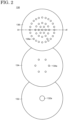
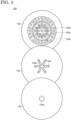
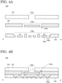
- FIG. 2 and FIG. 3 Schematic bottom and top views of an example of the head 130 are respectively shown in FIG. 2 and FIG. 3 , and schematic cross-sectional views along the straight line passing through the center of the head 130 (see the chain line A-A' in FIG. 2 ) are shown in FIG. 4A and FIG. 4B .
- the head 130 may have a first plate 132, a second plate 134, and a third plate 136. Note that a state where the first plate 132, the second plate 134, and the third plate 136 are separated from one another is shown in FIG. 2 to FIG. 4A for visibility.
- the planar shape of the head 130 (the shape observed from the normal direction of each plate.
- planar shape of the head 130 is a circle in the illustrated example, there is no restriction on the planar shape of the head 130, and a shape according to the substrate to be used may be adopted.
- the planar shape of the head 130 may be square, rectangular, or other polygonal shape.
- the first plate 132, the second plate 134, and the third plate 136 include a metal such as aluminum, iron, nickel, cobalt, and chromium as their constituent material (base material).
- the base materials include a metal such as aluminum, an alloy containing aluminum and magnesium, an alloy containing iron as a major component, or alloy containing nickel as a major component, or the like.
- As an alloy containing iron as a major component Invar containing iron and nickel, stainless steel containing iron and chromium, and the like are represented. Invar may contain manganese and carbon.
- Stainless steel may further contain nickel, molybdenum, carbon, and the like, and austenitic stainless steel, austenitic-ferritic stainless steel, ferritic stainless steel, and martensitic stainless steel may be used, for example.
- austenitic stainless steel austenitic-ferritic stainless steel
- ferritic stainless steel ferritic stainless steel
- martensitic stainless steel may be used, for example.
- an alloy containing nickel as a major component Inconel containing nickel, chromium, and iron is represented. Inconel may further contain molybdenum, titanium, aluminum, carbon, and the like.
- the first plate 132, the second plate 134, and the third plate 136 preferably have the same composition as one another.
- the head 130 In the head 130, the first plate 132 and the second plate 134 are bonded, and the second plate 134 and the third plate 136 are bonded so that the second plate 134 is sandwiched between the first plate 132 and the third plate 136 as shown in FIG. 4B . Moreover, the head 130 has a channel to allow the reactive gas to pass from the first plate 132 side to the third plate 136 side in a state where the first plate 132, the second plate 134, and the third plate 136 are bonded.
- the configuration of the channel may be set as appropriate.
- a through hole 132a is provided in the center of the first plate 132, and the reactive gas is supplied to the head 130 through the through hole 132a.
- the second plate 134 is provided with a recessed portion 134b overlapping the through hole 132a in a normal direction thereof and facing the first plate 132, and a plurality of through holes 134a is provided in the recessed portion 134b. Since the recessed portion 134b is located on the first plate 132 side, the reactive gas is introduced into the recessed portion 134b through the through hole 132a and then supplied to the third plate 136 side through the through holes 134a.
- the third plate 136 is provided with a recessed portion 136b overlapping the plurality of through holes 134a in a normal direction thereof and facing the second plate 134, and a plurality of through holes 136a is provided in the recessed portion 136b.
- the through holes 136a correspond to the openings 130a of the head 130 described above ( FIG. 1 ).
- the recessed portion 136b may be provided with one or a plurality of partitions 136c for controlling the flow of the reactive gas. Since the recessed portion 136b is located on the second plate 134 side, the reactive gas supplied from the second plate 134 side is supplied into the recessed portion 136b and then ejected through the through holes 136a (see dotted arrows in FIG. 4B ).
- the through holes 136a are formed relatively small.
- the diameter of the through holes 136a is set in the range equal to or larger than 0.3 mm and equal to or smaller than 5 mm.
- the diameters of the through holes 132a and 134a are larger than those of through holes 136a.
- one or a plurality of bolt holes may be provided on a top surface of the first plate 132 to fix the head 130 in the chamber 102.
- first plate 132 and the second plate 134 are bonded to each other by diffusion bonding.
- second plate 134 and the third plate 136 are also bonded to each other by diffusion bonding.
- first plate 132 and the second plate 134 are in direct contact with each other
- second plate 134 and the third plate 136 are also in direct contact with each other.
- there is no brazing material frequently used in metal-to-metal bonding there is no brazing material frequently used in metal-to-metal bonding, and no components derived from brazing materials (e.g.
- silicon, germanium, phosphorus, copper, and the like is present, or their concentrations are lower than their bulk concentrations in the first plate 132, the second plate 134, and the third plate 136. Furthermore, there is no brazing material or residue formed by the melting and resolidification of the brazing material on the surface facing the channel of the reactive gas.
- the brazing material or the residue thereof does not exist on the side wall of the through hole 132a, the bottom surface of the first plate 132 facing the recessed portion 134b, the top surface of the recessed portion 134b, the bottom surface of the second plate 134 facing the recessed portion 136b, the side wall of the through holes 134a, the top surface of the recessed portion 136b, the top and side surfaces of the partition 136c, the side wall of the through holes 136a, and the like.
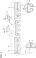
- the head 130 has a plating film 138 on the outer surfaces of the first plate 132, the second plate 134, and the third plate 136 as shown in the regions 140, 142, 144, 146, and the like represented in the enlarged view of FIG. 4B ( FIG. 5 ).
- the plating film 138 is continuous over the side surfaces of adjacent plates ( i.e.
- the plating film 138 is also present on the bottom surface of the third plate 136 and the top surface of the first plate 132 as can be understood from the enlarged schematic view of the regions 142 and 144. Furthermore, the plating film 138 is also provided on the inner surface facing the channel of the reactive gas.
- the plating film 138 exists on the sidewalls of the through holes 132a, 134a, and 136a, the top surface of the recessed portion 134b, the bottom surface of first plate 132 facing the recessed portion 134b, the top surface of recessed portion 136b, the bottom surface of the second plate 134 facing the recessed portion 136b, and the side surface and the top surface of the partition 136c.
- the plating film 138 contains nickel as its major component and may contain phosphorus as a secondary component.
- concentration of phosphorus is appropriately set in a range equal to or more than 1 wt% and equal to or less than 3 wt%, equal to or more than 2 wt% and equal to or less than 4 wt%, equal to or more than 5 wt% and equal to or less than 9 wt%, or equal to or more than 10 wt% and equal to or less than 15 wt%, for example.
- the thickness of the plating film 138 is also not restricted and may be appropriately set in a range equal to or more than 10 ⁇ m and equal to or less than 50 ⁇ m, equal to or more than 20 ⁇ m and equal to or less than 40 ⁇ m, or equal to or more than 25 ⁇ m and equal to or less than 35 ⁇ m, for example.
- the formation of the plating film 138 by electroless plating allows not only the outer surfaces of the first plate 132, the second plate 134, and the third plate 136 but also the inner surface facing the channel to be covered by the corrosion-resistant plating film 138. That is, the head 130 can be configured so that the first plate 132, the second plate 134, and the third plate 136 are not exposed from the plating film 138 and are entirely covered by the plating film 138. Therefore, corrosion of the head 130 by reactive gases during film formation can be effectively prevented. Hence, it is possible to provide a highly corrosion-resistant head which can be used not only in the formation and processing of metal films, but also in the formation and processing of ceramic-containing films, which require high temperatures.
- the expansion coefficient of the plating film 138 is relatively close to that of the base material included in the first plate 132, the second plate 134, and the third plate 136, which prevents peeling of the plating film 138 even when depositing films at high temperatures.
- the first plate 132, the second plate 134, and the third plate 136 are fabricated by cutting a corresponding metal or alloy plate as appropriate. As described above, the structure of the channel in the head 130 may be arbitrarily determined.
- the first plate 132, the second plate 134, and the third plate 136 are bonded by diffusion bonding ( FIG. 6 ).
- the first plate 132, the second plate 134, and the third plate 136 may be simultaneously bonded while placing the second plate 134 between the first plate 132 and the third plate 136, or two plates may be first bonded, which is followed by bonding the remaining plate.
- the diffusion bonding is performed by heating the plates at a temperature lower than the melting point of the base metal contained in the plates while applying pressure (see the white arrows in FIG. 6 ) between the plates under a reduced pressure.
- the pressure applied between the plates in the diffusion bonding may be selected from a range equal to or higher than 0.2 MPa and equal to or lower than 5 MPa, for example.
- the temperature for diffusion bonding may be selected from a range equal to or higher than 450 °C and lower than the melting point of the base metal.
- the first plate 132, the second plate 134, and the third plate 136 after bonding may be immersed in an electrolyte solution containing a nickel salt such as nickel sulfate or nickel chloride and a reducing agent such as sodium hypophosphite.
- the electrolyte may contain a catalyst such as copper, gold, silver, platinum, palladium, rhodium, and ruthenium.
- the immersion time is appropriately adjusted according to the thickness of the plating film 138 to be formed and the temperature of the electrolyte solution.
- the head 130 is cleaned with a cleaning solution such as water.
- the channel of the reactive gas formed in the head 130 is relatively narrow, and in particular, the diameter of the through hole 136a formed in the third plate 136 is approximately from several hundred ⁇ m to several mm ( e.g ., equal to or more than 0.3 mm and equal to or less than 5 mm).
- the composition, the thickness, the density, and other characteristics of the film to be formed on the substrate become non-uniform.
- the first plate 132, the second plate 134, and the third plate 136 are bonded using diffusion bonding in the manufacturing method of the head 130 according to an embodiment of the present invention, the influences caused by the presence of the brazing material or its residue are completely eliminated. As a result, it is possible to construct the channel in the head 130 as designed without affecting the channel of the reactive gas.
- the configuration of the head 130 is not limited thereto.
- the head 130 may be configured with two plates (the first plate 132 and the second plate 134). Since the through holes 134a in the second plate 134 correspond to the openings 130a in the head 130 in this case, the diameter thereof is preferably adjusted to be equal to or larger than 0.3 mm and equal to or smaller than 5 mm.
- the first plate 132 and the second plate 134 are configured to have a channel through which the reactive gas passes from the first plate 132 side to the second plate 134 side.
- the head 130 may be configured with four plates (the first plate 132 to the fourth plate 137). Since through holes 137a of the fourth plate 137 correspond to the openings 130a of the head 130, the diameter thereof is preferably adjusted to be equal to or larger than 0.3 mm and equal to or smaller than 5 mm.
- the first plate 132 to the fourth plate 137 are configured to have a channel through which the reactive gas passes from the first plate 132 side to the fourth plate 137 side. Similar to the case having three plates, the order of diffusion bonding is arbitrarily determined.
- the head 130 may be configured with five or more plates.
- a plurality of channels may be provided in the head 130 regardless of the number of plates.
- a plurality of channels may be provided in the head 130 in addition to a continuous channel passing through the second plate 134 and the third plate 136 from the through hole 132a in the first plate 132 to the through holes 137a in the fourth plate 137.
- This configuration allows for the simultaneous supply of reactive gases with different flow rates or a plurality of reactive gases with different molecular structures.
- a head 131 having different structure from that of the head 130 and a manufacturing method thereof are explained.
- An explanation for the structures the same as or similar to those described in the First Embodiment may be omitted.
- FIG. 8 A schematic cross-sectional view of the head 131 is shown in FIG. 8 .
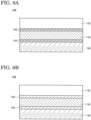
- a difference of the head 131 from the head 130 is that the head 131 has the plating film 138 not only on the surfaces of the first plate 132 to the third plate 136 but also between the first plate 132 and the second plate 134 and between the second plate 134 and the third plate 136. More specifically, as shown in the enlarged schematic views of the regions 150, 152, 154, and 156 in FIG. 8 and the enlarged schematic view of the region 158 ( FIG.
- the plating film 138 not only is the plating film 138 provided on the side surface and the top surface of the first plate 132, the side surface of the second plate 134, the top surface and the bottom surface of the third plate 136, and the inner surface facing the channel, but also the first plate 132 and the second plate 134 are bonded through the plating film 138, and the second plate 134 and the third plate 136 are bonded through the plating film 138.
- the first plate 132 and the second plate 134 are bonded via a bonding layer in direct contact with the first plate 132 and the second plate 134, and this bonding layer consists of the plating films 138 formed on the first plate 132 and the second plate 134.
- the second plate 134 and the third plate 136 are bonded via a bonding layer in direct contact with the second plate 134 and the third plate 136, and this bonding layer consists of the plating films 138 formed on the second plate 134 and the third plate 136.
- the head 131 is manufactured by applying electroless plating to each of the first plate 132, the second plate 134, and the third plate 136 to form the plating film 138 on the surfaces thereof, followed by diffusion-bonding the first plate 132, the second plate 134, and the third plate 136. Therefore, the base materials included in the first plate 132, the second plate 134, and the third plate 136 are preferred to have a higher melting point than the plating film 138. Specifically, it is preferable that the base material be Invar, Inconel, or stainless steel. Furthermore, there may be two layers of the plating film 138 between adjacent plates as shown in FIG. 9A , or the two layers of the plating film 138 may be integrated by diffusion bonding to form one layer of the plating film 138 ( FIG. 9B ).
- the corrosion-resistant plating film 138 Similar to the head 130, not only the inner surface facing the channel of the reactive gas but also the top surface, the side surface, and the bottom surface of the head 131 are covered by the corrosion-resistant plating film 138. Therefore, it is possible to provide a highly corrosion-resistant head which can be used in the formation of ceramic-containing films requiring high temperatures.
- the expansion coefficient of the plating film 138 is relatively close to those of the base materials included in the first plate 132, the second plate 134, and the third plate 136, peeling of the plating film 138 can be prevented even in film formation at a high temperature.
- diffusion bonding is used for bonding the first plate 132 and the second plate 134 and the bonding of the second plate 134 and the third plate 136, while brazing is not applied. Hence, the channel is not blocked by the brazing material or its residues, and it is possible to provide a head with a controlled structure capable of uniformly ejecting a reactive gas.
- the number of plates in the head 131 there is also no restriction on the number of plates in the head 131, and the number of plates may be two, four, or more. Regardless of the number of plates, adjacent plates are bonding to each other via the bonding layer in contact with these plates, and the bonding layer consists of the plating films 138 formed on the adjacent plates.
- stage 160 according to an embodiment of the present invention is explained.
- An explanation of the structures the same as or similar to those described in the First or Second embodiment may be omitted.
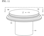
- FIG. 11 A schematic perspective view of the stage 160 is shown in FIG. 11 .
- the stage 160 is provided over a shaft 104 and includes, as its fundamental components, a first supporting plate 162 supported by the shaft 104, a second supporting plate 164 over the first supporting plate 162, and a third supporting plate 166 over the second supporting plate 164.
- a substrate is placed over the third supporting plate 166.
- the stage 160 may further be provided with an electrostatic chuck over the third supporting plate 166 to fix the substrate.
- the first supporting plate 162, the second supporting plate 164, and the third supporting plate 166 each have a disk shape in FIG. 11 , there are no restrictions on the shape of these plates, and these supporting plates may be shaped to fit the shape of the substrate to be used.
- the planar shape of the first supporting plate 162, the second supporting plate 164, and the third supporting plate 166 may be polygonal, including square and rectangular.
- the stage 160 is configured so that the planar shapes of the first supporting plate 162, the second supporting plate 164, and the third supporting plate 166 decrease in this order, the sizes of the planar shapes of these plates may be identical.
- the sizes of the planar shapes are different, there is no restriction on their order.
- the third supporting plate 166 may include, for example, a lower plate 166-1 and an upper plate 166-2 bonded to the lower plate 166-1, and one or a plurality of trenches 166a is formed in at least one of the lower plate 166-1 and the upper plate 166-2.
- a heater for heating which is not illustrated is placed in each trench 166a.
- a sheath heater, in which an electric heating wire is covered with an inorganic insulating material and the inorganic insulating material is further covered with a metal film, may be used as the heater.
- the outer diameter of the heater is, for example, equal to or larger than 3.0 mm and equal to or smaller than 11.0 mm, and thus the trench 166a may also be formed to have a width and a height which allow the heater having the aforementioned outer diameter to be accommodated.
- the heater is connected to a heater power supply 116 (see FIG. 1 ) and is controlled by the current supplied from the heater power supply 116.
- a through hole 174 reaching the trench 166a from a bottom surface of the first supporting plate 162 is provided in the first supporting plate 162 and the second supporting plate 164 to connect the heater to the heater power supply 116.
- the third supporting plate 166 may be structured with a single plate having the trench 166a capable of accommodating the heater. In this case, the heater may be placed between the third supporting plate 166 and the second supporting plate 164 and may be in contact with the second supporting plate 164.
- the second supporting plate 164 is sandwiched between the third supporting plate 166 and the first supporting plate 162 and bonded thereto.
- a channel 164a for circulating a cooling medium is formed in at least one of the first supporting plate 162 and the second supporting plate 164.
- the height and the width of the channel 164a may be selected from a range equal to or larger than 2 mm and equal to or smaller than 3 cm, for example.
- the channel 164a is connected to the temperature controller 120 through the shaft 104, and a temperature-controlled cooling medium is introduced into the channel 164a. Note that a through hole (not illustrated) is provided in the first supporting plate 162 to connect the channel 164a to the temperature controller 120.
- the stage 160 is further provided with a bottomed hole 170 for inserting a thermocouple to measure a temperature of the stage 160 as well as one or a plurality of through holes 172 for supplying a gas with high thermal conductivity such as helium to the surface of the third supporting plate 166.
- the bottom hole 170 may reach the third supporting plate 166 passing through the second supporting plate 164 or may not pass through the second supporting plate 164.
- the through hole 172 passes through the first supporting plate 162, the second supporting plate 164, and the third supporting plate 166 and is connected to a gas-supplying source which is not illustrated.
- the thermal energy of the heater can be efficiently transferred to the substrate by supplying a gas having high thermal conductivity to the gap between the third supporting plate 166 and the substrate through the through-hole 172.
- the first supporting plate 162 and the second supporting plate 164 of the stage 160 are bonded to each other by diffusion bonding as described below.
- the second supporting plate 164 and the third supporting plate 166 are also bonded to each other by diffusion bonding.
- the first supporting plate 162 and the second supporting plate 164 are in direct contact with each other, and the second supporting plate 164 and the third supporting plate 166 are also in direct contact with each other.
- the interface between the first supporting plate 162 and the second supporting plate 164 and the interface between the second supporting plate 164 and the third supporting plate 166 there is no brazing material frequently used in metal-to-metal bonding or its residue, and there is no component derived from the brazing material, or the concentration thereof is extremely lower than the concentration of these components in the bulk of the first supporting plate 162, the second supporting plate 164, and the third supporting plate 166. Furthermore, no brazing material nor residue thereof is present on the sidewalls of the through holes 172 forming the channels for the high thermal-conductivity gas, or the like.
- the plating film 138 can be formed by electroless plating after bonding the first supporting plate 162, the second supporting plate 164, and the third supporting plate 166.
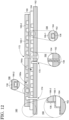
- the stage 160 is further provided with the plating film 138 as shown in the enlarged schematic views of the regions 190, 192, 194, and 196 in FIG. 12 .
- the plating film 138 covers the bottom surface and the side surface of the first supporting plate 162, the side surface of the second supporting plate 164, and the side surface and the top surface of the third supporting plate 166.
- the plating film 138 may also cover the top surface or the bottom surface of each supporting plate exposed from the adjacent supporting plate. As shown in the regions 190, 192 and the like, the plating film 138 is continuous over the adjacent supporting plates.
- the plating film 138 may cover the surface exposed to the trench 166a of the third supporting plate 166, the surfaces of the first supporting plate 162 and the second supporting plate 164 exposed to the channel 164a, the side wall of the through hole 174, the bottom surface and the side wall of the bottomed hole 170, and the side walls of the through holes 172. Note that the plating film 138 may not cover the surfaces which are not in contact with the reactive gas, specifically, the surface of the third supporting plate 166 exposed to the trench 166a, the surfaces of the first supporting plate 162 and the second supporting plate 164 exposed to the channel 164a, the side wall of the through hole 174, and the bottom surface or the side wall of the bottomed hole 170.
- the reactive gases i.e. , the bottom surface and the side surface of the first supporting plate 162, the side surface of the second supporting plate 164, the side surface and the top surface of the third supporting plate 166, the top surface or the bottom surface of each plate exposed from the adjacent plate, and
- the lower plate 166-1 and the upper plate 166-2 are bonded with the heater, which is not illustrated, arranged in the trench 166a to fabricate the third supporting plate 166 ( FIG. 13A ).
- the bonding at this time may be performed by diffusion bonding or brazing. This is because the influence of the residual brazing material is negligible due to the large size of the trench 166a compared with the through holes 136a formed in the third plate 136 of the head 130 and because the brazing material remaining in the through hole 172 can be relatively readily removed mechanically before bonding the second supporting plate 164 and the first supporting plate 162.
- the brazing material or the residue thereof is present therebetween.
- the first supporting plate 162, the second supporting plate 164, and the third supporting plate 166 are bonded ( FIG. 13B ).
- the first supporting plate 162, the second supporting plate 164, and the third supporting plate 166 may be simultaneously bonded with the second supporting plate 164 sandwiched between the first supporting plate 162 and the third supporting plate 166, or two supporting plates may be first bonded and then the remaining supporting plate may be bonded. Diffusion bonding is used in this bonding process.
- the head 130 is cleaned with a cleaning solution such as water.
- a cleaning solution such as water.
- diffusion bonding is used in bonding the first supporting plate 162, the second supporting plate 164, and the third supporting plate 166, and no bonding by brazing is performed. Therefore, the brazing material used in brazing and the residue thereof do not exist not only on the outer surface but also in the channel 164a, the through holes 172, and the like. Similar to the through hole 136a of the head 130, the diameter variation of the plurality of through holes 172 are preferred to be small to uniformly eject the high thermal-conductivity gas. Furthermore, the through holes 172 are also designed to have a relatively small diameter ( e.g. , equal to or larger than 0.3 mm and equal to or smaller than 5 mm).
- the first supporting plate 162, the second supporting plate 164, and the third supporting plate 166 are bonded using diffusion bonding in the manufacturing method of the stage 160 according to an embodiment of the present invention, the influences of the residual brazing material or the residue thereof are completely eliminated and the high thermal-conductivity gas can be uniformly supplied to the upper surface of the stage 160 without affecting the channel of the high thermal-conductivity gas.
- the stage 160 may be manufactured by applying electroless plating to each of the first supporting plate 162, the second supporting plate 164, and the third supporting plate 166, followed by bonding these plates.
- the stage 160 according to this modified example may have the plating film 138 between the first supporting plate 162 and the second supporting plate 164 and between the second supporting plate 164 and the third supporting plate 166.
- the plating film 138 provided on the side surface and the bottom surface of the first supporting plate 162, the side surface of the second supporting plate 164, the top surface and the side surface of the third supporting plate 166, the surfaces of each plate exposed from adjacent plates, and the side walls of the through holes 172, but also the first supporting plate 162 and the second supporting plate 164 are bonded through the plating film 138, and the second supporting plate 164 and the third supporting plate 166 are bonded through the plating film 138.
- first supporting plate 162 and the second supporting plate 164 are bonded through a bonding layer in direct contact with the first supporting plate 162 and the second supporting plate 164, and this bonding layer consists of the plating films 138 formed on the first supporting plate 162 and the second supporting plate 164.
- second supporting plate 164 and the third supporting plate 166 are bonded through a bonding layer in direct contact with the second supporting plate 164 and the third supporting plate 166, and this bonding layer consists of the plating films 138 formed on the second supporting plate 164 and the third supporting plate 166.
- the stage 160 according to this modified example is manufactured by applying electroless plating to each of the first supporting plate 162, the second supporting plate 164, and the third supporting plate 166 to form the plating film 138 on the surface thereof, followed by diffusion-bonding the first supporting plate 162, the second supporting plate 164, and the third supporting plate 166. Therefore, the base materials included in the first supporting plate 162, the second supporting plate 164, and the third supporting plate 166 are preferred to have a higher melting point than the plating film 138. Specifically, the base materials are preferred to be Invar, Inconel, or stainless steel.
- plating film 138 there may be two layers of the plating film 138 between adjacent supporting plates, and the two layers of the plating film 138 may be integrated by diffusion bonding to form one layer of the plating film 138, similar to the head 130 (see FIG. 9A and FIG. 9B ).
- the stage 160 In the stage 160 according to this modified example, not only the side walls of the through holes 172 but also the top surface, the side surface, and the bottom surface are coated with the highly corrosion-resistant plating film 138. Therefore, it is possible to provide a highly corrosion-resistant head which can be used in the formation of ceramic-containing films where high temperatures are required.
- the expansion coefficient of the plating film 138 is relatively close to those of the base materials included in the first supporting plate 162, the second supporting plate 164, and the third supporting plate 166, peeling of the plating film 138 can also be prevented even in film formation at high temperatures.
- diffusion bonding is used but the brazing is not performed for the bonding of the first supporting plate 162 and the second supporting plate 164 and for the bonding of the second supporting plate 164 and the third supporting plate 166. Therefore, the through holes 172 are not blocked by the brazing material or the residue thereof, and the high thermal-conductivity gas can be uniformly supplied to the substrate side.
Landscapes
- Chemical & Material Sciences (AREA)
- Engineering & Computer Science (AREA)
- Mechanical Engineering (AREA)
- General Chemical & Material Sciences (AREA)
- Chemical Kinetics & Catalysis (AREA)
- Materials Engineering (AREA)
- Metallurgy (AREA)
- Organic Chemistry (AREA)
- Manufacturing & Machinery (AREA)
- Physics & Mathematics (AREA)
- Plasma & Fusion (AREA)
- Analytical Chemistry (AREA)
- Particle Formation And Scattering Control In Inkjet Printers (AREA)
- Nozzles (AREA)
- Chemically Coating (AREA)
- Other Surface Treatments For Metallic Materials (AREA)
- Chemical Vapour Deposition (AREA)
Abstract
Description
- An embodiment of the present invention relates to a head for ejecting reactive gas for film formation in an apparatus for forming or processing thin films and a manufacturing method thereof. Alternatively, an embodiment of the present invention relates to a stage for placing a substrate in an apparatus for forming or processing thin films and a manufacturing method thereof.
- Semiconductor devices are installed in almost all electronic devices and play an important role in the function of the electronic devices. Semiconductor devices are devices utilizing the semiconductor properties of silicon and the like and are structured by appropriately stacking patterned thin films of semiconductors, insulators, and conductors over a substrate. These thin films are formed by an evaporation method, a sputtering method, a chemical vapor deposition (CVD) method, or a chemical reaction of a substrate and are processed (patterned) by photolithography processes. In the formation and patterning of thin films, highly reactive gases such as halogen-based gases are used as gases for film formation. For example,
patent literature 1 discloses a configuration of a head (also called a shower head) for ejecting highly reactive gases, in which a corrosion-resistant film such as a ceramic spraying film is attached by a sealing member to the portion of the head in contact with the highly reactive gas. - Patent Literature 1:
Japanese Laid-Open Patent Publication No. 2020-88317 - An object of an embodiment of the present invention is to provide a film-forming component having a novel structure and capable of uniformly ejecting a gas for film formation in a film-forming apparatus and a manufacturing method thereof. For example, an object of an embodiment of the present invention is to provide a head capable of uniformly ejecting a gas for film formation in a film-forming apparatus, a stage for mounting a substrate which is an object for film formation, and a manufacturing method thereof.
- An embodiment of the present invention is a method for manufacturing a head for ejecting a reactive gas for film formation. The method includes: diffusion-bonding a first plate and a second plate to each other; and forming, after the diffusion bonding, a nickel-containing film on surfaces of the first plate and the second plate with electroless plating. The first plate and the second plate are configured to have a channel through which the reactive gas passes from a side of the first plate to a side of the second plate in a state where the first plate and the second plate are bonded.
- An embodiment of the present invention is a method for manufacturing a head for ejecting a reactive gas for film formation. The method includes: forming a nickel-containing film on surfaces of a first plate and a second plate with electroless plating; and diffusion-bonding the first plate and the second plate to each other after the formation of the nickel-containing film. The first plate and the second plate are configured to have a channel through which the reactive gas passes from a side of the first plate to a side of the second plate in a state where the first plate and the second plate are bonded.
- An embodiment of the present invention is a head for ejecting a reactive gas for film formation. The head includes a first plate, a second plate diffusion-bonded to the first plate, and a nickel-containing film covering surfaces of the first plate and the second plate. The first plate and the second plate are configured to have a channel through which the reactive gas passes from a side of the first plate to a side of the second plate.
- An embodiment of the present invention is a head for ejecting a reactive gas for film formation. The head includes a first plate and a second plate each coated with a nickel-containing film. The first plate and the second plate are bonded to each other through a first bonding layer in contact with the first plate and the second plate. The first bonding layer consists of the nickel-containing films of the first plate and the second plate. The first plate and the second plate are configured to have a channel through which the reactive gas passes from a side of the first plate to a side of the second plate.
-
-
FIG. 1 is a schematic cross-sectional view of a film-forming apparatus equipped with a head or a stage according to an embodiment of the present invention. -
FIG. 2 is a schematic bottom view of a head according to an embodiment of the present invention. -
FIG. 3 is a schematic top view of a head according to an embodiment of the present invention. -
FIG. 4A is a schematic cross-sectional view of a head according to an embodiment of the present invention. -
FIG. 4B is a schematic cross-sectional view of a head according to an embodiment of the present invention. -
FIG. 5 is a schematic cross-sectional view of a head according to an embodiment of the present invention. -
FIG. 6 is a schematic cross-sectional view showing a manufacturing method of a head according to an embodiment of the present invention. -
FIG. 7A is a schematic cross-sectional view of a head according to an embodiment of the present invention. -
FIG. 7B is a schematic cross-sectional view of a head according to an embodiment of the present invention. -
FIG. 8 is a schematic cross-sectional view of a head according to an embodiment of the present invention. -
FIG. 9A is a schematic cross-sectional view of a part of a head according to an embodiment of the present invention. -
FIG. 9B is a schematic cross-sectional view of a part of a head according to an embodiment of the present invention. -
FIG. 10 is a schematic cross-sectional view showing a manufacturing method of a head according to an embodiment of the present invention. -
FIG. 11 is a schematic perspective view of a stage according to an embodiment of the present invention. -
FIG. 12 is a schematic cross-sectional view of a stage according to an embodiment of the present invention. -
FIG. 13A is a schematic cross-sectional view showing a manufacturing method of a stage according to an embodiment of the present invention. -
FIG. 13B is a schematic cross-sectional view showing a manufacturing method of a stage according to an embodiment of the present invention. -
FIG. 14 is a schematic cross-sectional view of a stage according to an embodiment of the present invention. - Hereinafter, each embodiment of the present invention is explained with reference to the drawings. The invention can be implemented in a variety of different modes within its concept and should not be interpreted only within the disclosure of the embodiments exemplified below.
- The drawings may be illustrated so that the width, thickness, shape, and the like are illustrated more schematically compared with those of the actual modes in order to provide a clearer explanation. However, they are only an example, and do not limit the interpretation of the invention. In the specification and the drawings, the same reference number is provided to an element that is the same as that which appears in preceding drawings, and a detailed explanation may be omitted as appropriate.
- In the specification and drawings, the reference number is used when plural structures which are the same as or similar to each other are collectively represented, while a hyphen and a natural number are further used when these structures are independently represented.
- In the specification and the claims, an expression "a structure is exposed from another structure" means a mode in which a part of the structure is not covered by the other structure and includes a mode where the part uncovered by the other structure is further covered by another structure. In addition, a mode expressed by this expression includes a mode where a structure is not in contact with other structures.
- In this embodiment, a
head 130 for ejecting reactive gases (hereinafter, simply referred to as reactive gases) according to an embodiment of the present invention is described. Thehead 130 is installed in film-forming apparatuses such as a CVD apparatus and an atomic layer deposition (ALD) apparatus and film-processing apparatuses such as an ashing apparatus and a dry-etching apparatus (hereinafter, film-forming apparatuses and film-processing apparatuses may be collectively referred to as film-forming apparatuses, and film formation and film processing may also be collectively referred to as film formation) and a component for ejecting reactive gases. A variety of gases may be used as the reactive gases, depending on the films to be fabricated. The reactive gas may be liquid at room temperature. For example, silane-based gases such as monosilane, dichlorosilane, and trichlorosilane, halogen-containing gases without a metal element such as fluorine, hydrogen fluoride, chlorine, and nitrogen trifluoride, halogen-containing gases including a metal element such as tungsten hexafluoride, germanium tetrachloride, molybdenum fluoride, and tungsten chloride, alkylmetals such as trialkylaluminum and trialkylgallium, fluorine-based etching gases such as sulfur hexafluoride, carbon tetrafluoride, and trifluoromethane, and the like are represented. For example, the use of silane-based gases allows the formation of thin films of silicon, silicon oxide, silicon nitride, and the like, while the use of tungsten fluoride, trimethylaluminum, or the like leads to the formation of thin metal films such as tungsten and aluminum. These reactive gases are generally highly reactive and corrosive, and thehead 130 is provided with a configuration to prevent corrosion by reactive gases as described below. - Hereinafter, a CVD apparatus is used as an example of film-forming apparatuses, and the structure of the
head 130 used in the CVD apparatus is explained.FIG. 1 is a schematic cross-sectional view of theCVD apparatus 100. TheCVD apparatus 100 has achamber 102 to provide a space where reactive gases are chemically reacted. Anexhaust device 108 is connected to thechamber 102 by which the pressure in thechamber 102 can be reduced. Thehead 130 is provided in thechamber 102, and a reactive gas is supplied to thehead 130 from a source of the reactive gas, which is not illustrated (see the straight arrow in the drawing). Thehead 130 is provided with a plurality ofopenings 130a, and the reactive gas is supplied into thechamber 102 through theopenings 130a. - A
microwave source 110 may be connected to thechamber 102. Microwaves generated by themicrowave source 110 are introduced into thechamber 102 to plasmatize the reactive gas. As a result, chemical reactions of the reactive gas are promoted by a variety of active species included in the plasma, and the products obtained by the chemical reactions are deposited over a substrate to form a thin film. Astage 160 according to an embodiment of the present invention is provided at a lower portion of thechamber 102, by which deposition of thin films can be performed in a state where the substrate is placed over thestage 160. Thestage 160 is described in the Third Embodiment. Amagnet 112 may be further provided on a side of thechamber 102. Themagnet 112 may be a permanent magnet or an electromagnet with an electromagnetic coil. Themagnet 112 creates a magnetic field component parallel to thestage 160 and a surface of the substrate by which the electrons in the plasma resonate under the Lorentz force in conjunction with the microwave electric field and are bound to thestage 160 and the surface of the substrate. As a result, a high-density plasma can be generated on the substrate surface. - The
stage 160 is provided over ashaft 104. Thestage 160 may further be connected to apower supply 114 for supplying high-frequency power to thestage 160, aheater power supply 116 for controlling a heater built into thestage 160, apower supply 118 for an electrostatic chuck disposed over thestage 160, atemperature controller 120 for controlling a temperature of a cooling medium circulated in thestage 160, and the like. TheCVD apparatus 100 may further be provided with a rotation-controlling device (not illustrated) for rotating thestage 160 as an optional component. - In the above example, the
head 130 is provided over thestage 160, and the reactive gas is supplied downward toward thestage 160. However, thestage 160 may be provided over thehead 130, and the reactive gas may be supplied from thehead 130 to thestage 160 side while the substrate is placed under thestage 160. - Schematic bottom and top views of an example of the
head 130 are respectively shown inFIG. 2 andFIG. 3 , and schematic cross-sectional views along the straight line passing through the center of the head 130 (see the chain line A-A' inFIG. 2 ) are shown inFIG. 4A and FIG. 4B . As can be understood from these drawings, thehead 130 may have afirst plate 132, asecond plate 134, and athird plate 136. Note that a state where thefirst plate 132, thesecond plate 134, and thethird plate 136 are separated from one another is shown inFIG. 2 to FIG. 4A for visibility. Although the planar shape of the head 130 (the shape observed from the normal direction of each plate. The same is applied hereinafter.) is a circle in the illustrated example, there is no restriction on the planar shape of thehead 130, and a shape according to the substrate to be used may be adopted. For example, the planar shape of thehead 130 may be square, rectangular, or other polygonal shape. - The
first plate 132, thesecond plate 134, and thethird plate 136 include a metal such as aluminum, iron, nickel, cobalt, and chromium as their constituent material (base material). Specifically, the base materials include a metal such as aluminum, an alloy containing aluminum and magnesium, an alloy containing iron as a major component, or alloy containing nickel as a major component, or the like. As an alloy containing iron as a major component, Invar containing iron and nickel, stainless steel containing iron and chromium, and the like are represented. Invar may contain manganese and carbon. Stainless steel may further contain nickel, molybdenum, carbon, and the like, and austenitic stainless steel, austenitic-ferritic stainless steel, ferritic stainless steel, and martensitic stainless steel may be used, for example. As an alloy containing nickel as a major component, Inconel containing nickel, chromium, and iron is represented. Inconel may further contain molybdenum, titanium, aluminum, carbon, and the like. Thefirst plate 132, thesecond plate 134, and thethird plate 136 preferably have the same composition as one another. - In the
head 130, thefirst plate 132 and thesecond plate 134 are bonded, and thesecond plate 134 and thethird plate 136 are bonded so that thesecond plate 134 is sandwiched between thefirst plate 132 and thethird plate 136 as shown inFIG. 4B . Moreover, thehead 130 has a channel to allow the reactive gas to pass from thefirst plate 132 side to thethird plate 136 side in a state where thefirst plate 132, thesecond plate 134, and thethird plate 136 are bonded. - The configuration of the channel may be set as appropriate. For example, in the example shown in
FIG. 2 to FIG. 4B , a throughhole 132a is provided in the center of thefirst plate 132, and the reactive gas is supplied to thehead 130 through the throughhole 132a. Thesecond plate 134 is provided with a recessedportion 134b overlapping the throughhole 132a in a normal direction thereof and facing thefirst plate 132, and a plurality of throughholes 134a is provided in the recessedportion 134b. Since the recessedportion 134b is located on thefirst plate 132 side, the reactive gas is introduced into the recessedportion 134b through the throughhole 132a and then supplied to thethird plate 136 side through the throughholes 134a. Similarly, thethird plate 136 is provided with a recessedportion 136b overlapping the plurality of throughholes 134a in a normal direction thereof and facing thesecond plate 134, and a plurality of throughholes 136a is provided in the recessedportion 136b. The throughholes 136a correspond to theopenings 130a of thehead 130 described above (FIG. 1 ). The recessedportion 136b may be provided with one or a plurality ofpartitions 136c for controlling the flow of the reactive gas. Since the recessedportion 136b is located on thesecond plate 134 side, the reactive gas supplied from thesecond plate 134 side is supplied into the recessedportion 136b and then ejected through the throughholes 136a (see dotted arrows inFIG. 4B ). In order to uniformly supply the reactive gas, the throughholes 136a are formed relatively small. For example, the diameter of the throughholes 136a is set in the range equal to or larger than 0.3 mm and equal to or smaller than 5 mm. The diameters of the throughholes holes 136a. - Although not illustrated, one or a plurality of bolt holes may be provided on a top surface of the
first plate 132 to fix thehead 130 in thechamber 102. - As described below, the
first plate 132 and thesecond plate 134 are bonded to each other by diffusion bonding. Similarly, thesecond plate 134 and thethird plate 136 are also bonded to each other by diffusion bonding. Thus, thefirst plate 132 and thesecond plate 134 are in direct contact with each other, and thesecond plate 134 and thethird plate 136 are also in direct contact with each other. In addition, at the interface between thefirst plate 132 and thesecond plate 134 and the interface between thesecond plate 134 and thethird plate 136, there is no brazing material frequently used in metal-to-metal bonding, and no components derived from brazing materials (e.g., silicon, germanium, phosphorus, copper, and the like) is present, or their concentrations are lower than their bulk concentrations in thefirst plate 132, thesecond plate 134, and thethird plate 136. Furthermore, there is no brazing material or residue formed by the melting and resolidification of the brazing material on the surface facing the channel of the reactive gas. Specifically, the brazing material or the residue thereof does not exist on the side wall of the throughhole 132a, the bottom surface of thefirst plate 132 facing the recessedportion 134b, the top surface of the recessedportion 134b, the bottom surface of thesecond plate 134 facing the recessedportion 136b, the side wall of the throughholes 134a, the top surface of the recessedportion 136b, the top and side surfaces of thepartition 136c, the side wall of the throughholes 136a, and the like. - As described below, in the manufacturing process of the
head 130, after diffusion-bonding thefirst plate 132, thesecond plate 134, and thethird plate 136, a plating film containing nickel (nickel-containing film) is further provided by electroless plating. Therefore, thehead 130 has aplating film 138 on the outer surfaces of thefirst plate 132, thesecond plate 134, and thethird plate 136 as shown in theregions FIG. 4B (FIG. 5 ). For example, as can be understood from the enlarged schematic view of theregion 140, theplating film 138 is continuous over the side surfaces of adjacent plates (i.e., thefirst plate 132 and thesecond plate 134, and thesecond plate 134 and the third plate 136). Moreover, theplating film 138 is also present on the bottom surface of thethird plate 136 and the top surface of thefirst plate 132 as can be understood from the enlarged schematic view of theregions plating film 138 is also provided on the inner surface facing the channel of the reactive gas. That is, as can be understood from the enlarged schematic views of theregions plating film 138 exists on the sidewalls of the throughholes portion 134b, the bottom surface offirst plate 132 facing the recessedportion 134b, the top surface of recessedportion 136b, the bottom surface of thesecond plate 134 facing the recessedportion 136b, and the side surface and the top surface of thepartition 136c. - The
plating film 138 contains nickel as its major component and may contain phosphorus as a secondary component. The concentration of phosphorus is appropriately set in a range equal to or more than 1 wt% and equal to or less than 3 wt%, equal to or more than 2 wt% and equal to or less than 4 wt%, equal to or more than 5 wt% and equal to or less than 9 wt%, or equal to or more than 10 wt% and equal to or less than 15 wt%, for example. The thickness of theplating film 138 is also not restricted and may be appropriately set in a range equal to or more than 10 µm and equal to or less than 50 µm, equal to or more than 20 µm and equal to or less than 40 µm, or equal to or more than 25 µm and equal to or less than 35 µm, for example. - The formation of the
plating film 138 by electroless plating allows not only the outer surfaces of thefirst plate 132, thesecond plate 134, and thethird plate 136 but also the inner surface facing the channel to be covered by the corrosion-resistant plating film 138. That is, thehead 130 can be configured so that thefirst plate 132, thesecond plate 134, and thethird plate 136 are not exposed from theplating film 138 and are entirely covered by theplating film 138. Therefore, corrosion of thehead 130 by reactive gases during film formation can be effectively prevented. Hence, it is possible to provide a highly corrosion-resistant head which can be used not only in the formation and processing of metal films, but also in the formation and processing of ceramic-containing films, which require high temperatures. In addition, unlike the films containing inorganic oxides such as ceramics, the expansion coefficient of theplating film 138 is relatively close to that of the base material included in thefirst plate 132, thesecond plate 134, and thethird plate 136, which prevents peeling of theplating film 138 even when depositing films at high temperatures. - The
first plate 132, thesecond plate 134, and thethird plate 136 are fabricated by cutting a corresponding metal or alloy plate as appropriate. As described above, the structure of the channel in thehead 130 may be arbitrarily determined. - The
first plate 132, thesecond plate 134, and thethird plate 136 are bonded by diffusion bonding (FIG. 6 ). Thefirst plate 132, thesecond plate 134, and thethird plate 136 may be simultaneously bonded while placing thesecond plate 134 between thefirst plate 132 and thethird plate 136, or two plates may be first bonded, which is followed by bonding the remaining plate. The diffusion bonding is performed by heating the plates at a temperature lower than the melting point of the base metal contained in the plates while applying pressure (see the white arrows inFIG. 6 ) between the plates under a reduced pressure. The pressure applied between the plates in the diffusion bonding may be selected from a range equal to or higher than 0.2 MPa and equal to or lower than 5 MPa, for example. The temperature for diffusion bonding may be selected from a range equal to or higher than 450 °C and lower than the melting point of the base metal. - After the bonding is completed, electroless plating is performed to produce the
head 130 shown inFIG. 5 and the like. For example, thefirst plate 132, thesecond plate 134, and thethird plate 136 after bonding may be immersed in an electrolyte solution containing a nickel salt such as nickel sulfate or nickel chloride and a reducing agent such as sodium hypophosphite. The electrolyte may contain a catalyst such as copper, gold, silver, platinum, palladium, rhodium, and ruthenium. The immersion time is appropriately adjusted according to the thickness of theplating film 138 to be formed and the temperature of the electrolyte solution. After the electroless plating is completed, thehead 130 is cleaned with a cleaning solution such as water. - In the manufacturing method of the
head 130 according to an embodiment of the present invention, diffusion bonding is used in bonding thefirst plate 132, thesecond plate 134, and thethird plate 136, and brazing is not used in the bonding. Therefore, the brazing material used in brazing and its residues are not present on the outer surfaces or in the channel. As described above, in order to uniformly eject the reactive gas, the channel of the reactive gas formed in thehead 130 is relatively narrow, and in particular, the diameter of the throughhole 136a formed in thethird plate 136 is approximately from several hundred µm to several mm (e.g., equal to or more than 0.3 mm and equal to or less than 5 mm). Therefore, if a brazing material or its residues remain in the channel including the throughholes 136a, a part of the channel of the reactive gas is blocked, making it difficult to uniformly eject the reactive gas. As a result, the composition, the thickness, the density, and other characteristics of the film to be formed on the substrate become non-uniform. However, since thefirst plate 132, thesecond plate 134, and thethird plate 136 are bonded using diffusion bonding in the manufacturing method of thehead 130 according to an embodiment of the present invention, the influences caused by the presence of the brazing material or its residue are completely eliminated. As a result, it is possible to construct the channel in thehead 130 as designed without affecting the channel of the reactive gas. - Although the
head 130 has three plates diffusion-bonded to one another in the example above, the configuration of thehead 130 is not limited thereto. For example, as shown inFIG. 7A , thehead 130 may be configured with two plates (thefirst plate 132 and the second plate 134). Since the throughholes 134a in thesecond plate 134 correspond to theopenings 130a in thehead 130 in this case, the diameter thereof is preferably adjusted to be equal to or larger than 0.3 mm and equal to or smaller than 5 mm. Thefirst plate 132 and thesecond plate 134 are configured to have a channel through which the reactive gas passes from thefirst plate 132 side to thesecond plate 134 side. - Alternatively, as shown in
FIG. 7B , thehead 130 may be configured with four plates (thefirst plate 132 to the fourth plate 137). Since throughholes 137a of thefourth plate 137 correspond to theopenings 130a of thehead 130, the diameter thereof is preferably adjusted to be equal to or larger than 0.3 mm and equal to or smaller than 5 mm. Thefirst plate 132 to thefourth plate 137 are configured to have a channel through which the reactive gas passes from thefirst plate 132 side to thefourth plate 137 side. Similar to the case having three plates, the order of diffusion bonding is arbitrarily determined. Although not illustrated, thehead 130 may be configured with five or more plates. - Furthermore, a plurality of channels may be provided in the
head 130 regardless of the number of plates. For example, as shown inFIG. 7B , in addition to a continuous channel passing through thesecond plate 134 and thethird plate 136 from the throughhole 132a in thefirst plate 132 to the throughholes 137a in thefourth plate 137, one or a plurality ofchannels 133 independent from this channel may be provided in thehead 130. This configuration allows for the simultaneous supply of reactive gases with different flow rates or a plurality of reactive gases with different molecular structures. - In this embodiment, a
head 131 having different structure from that of thehead 130 and a manufacturing method thereof are explained. An explanation for the structures the same as or similar to those described in the First Embodiment may be omitted. - A schematic cross-sectional view of the
head 131 is shown inFIG. 8 . As can be understood fromFIG. 8 , a difference of thehead 131 from thehead 130 is that thehead 131 has theplating film 138 not only on the surfaces of thefirst plate 132 to thethird plate 136 but also between thefirst plate 132 and thesecond plate 134 and between thesecond plate 134 and thethird plate 136. More specifically, as shown in the enlarged schematic views of theregions FIG. 8 and the enlarged schematic view of the region 158 (FIG. 9A ), not only is theplating film 138 provided on the side surface and the top surface of thefirst plate 132, the side surface of thesecond plate 134, the top surface and the bottom surface of thethird plate 136, and the inner surface facing the channel, but also thefirst plate 132 and thesecond plate 134 are bonded through theplating film 138, and thesecond plate 134 and thethird plate 136 are bonded through theplating film 138. In other words, thefirst plate 132 and thesecond plate 134 are bonded via a bonding layer in direct contact with thefirst plate 132 and thesecond plate 134, and this bonding layer consists of the platingfilms 138 formed on thefirst plate 132 and thesecond plate 134. Similarly, thesecond plate 134 and thethird plate 136 are bonded via a bonding layer in direct contact with thesecond plate 134 and thethird plate 136, and this bonding layer consists of the platingfilms 138 formed on thesecond plate 134 and thethird plate 136. - As can be understood from the schematic cross-sectional view shown in
FIG. 10 , unlike thehead 130, thehead 131 is manufactured by applying electroless plating to each of thefirst plate 132, thesecond plate 134, and thethird plate 136 to form theplating film 138 on the surfaces thereof, followed by diffusion-bonding thefirst plate 132, thesecond plate 134, and thethird plate 136. Therefore, the base materials included in thefirst plate 132, thesecond plate 134, and thethird plate 136 are preferred to have a higher melting point than theplating film 138. Specifically, it is preferable that the base material be Invar, Inconel, or stainless steel. Furthermore, there may be two layers of theplating film 138 between adjacent plates as shown inFIG. 9A , or the two layers of theplating film 138 may be integrated by diffusion bonding to form one layer of the plating film 138 (FIG. 9B ). - Similar to the
head 130, not only the inner surface facing the channel of the reactive gas but also the top surface, the side surface, and the bottom surface of thehead 131 are covered by the corrosion-resistant plating film 138. Therefore, it is possible to provide a highly corrosion-resistant head which can be used in the formation of ceramic-containing films requiring high temperatures. In addition, since the expansion coefficient of theplating film 138 is relatively close to those of the base materials included in thefirst plate 132, thesecond plate 134, and thethird plate 136, peeling of theplating film 138 can be prevented even in film formation at a high temperature. Furthermore, diffusion bonding is used for bonding thefirst plate 132 and thesecond plate 134 and the bonding of thesecond plate 134 and thethird plate 136, while brazing is not applied. Hence, the channel is not blocked by the brazing material or its residues, and it is possible to provide a head with a controlled structure capable of uniformly ejecting a reactive gas. - There is also no restriction on the number of plates in the
head 131, and the number of plates may be two, four, or more. Regardless of the number of plates, adjacent plates are bonding to each other via the bonding layer in contact with these plates, and the bonding layer consists of the platingfilms 138 formed on the adjacent plates. - In this embodiment, the
stage 160 according to an embodiment of the present invention is explained. An explanation of the structures the same as or similar to those described in the First or Second embodiment may be omitted. - A schematic perspective view of the
stage 160 is shown inFIG. 11 . As shown inFIG. 11 , thestage 160 is provided over ashaft 104 and includes, as its fundamental components, a first supportingplate 162 supported by theshaft 104, a second supportingplate 164 over the first supportingplate 162, and a third supportingplate 166 over the second supportingplate 164. A substrate is placed over the third supportingplate 166. Although not illustrated, thestage 160 may further be provided with an electrostatic chuck over the third supportingplate 166 to fix the substrate. Although the first supportingplate 162, the second supportingplate 164, and the third supportingplate 166 each have a disk shape inFIG. 11 , there are no restrictions on the shape of these plates, and these supporting plates may be shaped to fit the shape of the substrate to be used. For example, the planar shape of the first supportingplate 162, the second supportingplate 164, and the third supportingplate 166 may be polygonal, including square and rectangular. Although thestage 160 is configured so that the planar shapes of the first supportingplate 162, the second supportingplate 164, and the third supportingplate 166 decrease in this order, the sizes of the planar shapes of these plates may be identical. In addition, when the sizes of the planar shapes are different, there is no restriction on their order. - A schematic cross-sectional view of the
stage 160 is shown inFIG. 12 . The third supportingplate 166 may include, for example, a lower plate 166-1 and an upper plate 166-2 bonded to the lower plate 166-1, and one or a plurality oftrenches 166a is formed in at least one of the lower plate 166-1 and the upper plate 166-2. A heater for heating which is not illustrated is placed in eachtrench 166a. A sheath heater, in which an electric heating wire is covered with an inorganic insulating material and the inorganic insulating material is further covered with a metal film, may be used as the heater. The outer diameter of the heater is, for example, equal to or larger than 3.0 mm and equal to or smaller than 11.0 mm, and thus thetrench 166a may also be formed to have a width and a height which allow the heater having the aforementioned outer diameter to be accommodated. The heater is connected to a heater power supply 116 (seeFIG. 1 ) and is controlled by the current supplied from theheater power supply 116. Note that a throughhole 174 reaching thetrench 166a from a bottom surface of the first supportingplate 162 is provided in the first supportingplate 162 and the second supportingplate 164 to connect the heater to theheater power supply 116. Although not illustrated, the third supportingplate 166 may be structured with a single plate having thetrench 166a capable of accommodating the heater. In this case, the heater may be placed between the third supportingplate 166 and the second supportingplate 164 and may be in contact with the second supportingplate 164. - The second supporting
plate 164 is sandwiched between the third supportingplate 166 and the first supportingplate 162 and bonded thereto. Achannel 164a for circulating a cooling medium is formed in at least one of the first supportingplate 162 and the second supportingplate 164. The height and the width of thechannel 164a may be selected from a range equal to or larger than 2 mm and equal to or smaller than 3 cm, for example. Thechannel 164a is connected to thetemperature controller 120 through theshaft 104, and a temperature-controlled cooling medium is introduced into thechannel 164a. Note that a through hole (not illustrated) is provided in the first supportingplate 162 to connect thechannel 164a to thetemperature controller 120. - The
stage 160 is further provided with a bottomedhole 170 for inserting a thermocouple to measure a temperature of thestage 160 as well as one or a plurality of throughholes 172 for supplying a gas with high thermal conductivity such as helium to the surface of the third supportingplate 166. Thebottom hole 170 may reach the third supportingplate 166 passing through the second supportingplate 164 or may not pass through the second supportingplate 164. The throughhole 172 passes through the first supportingplate 162, the second supportingplate 164, and the third supportingplate 166 and is connected to a gas-supplying source which is not illustrated. The thermal energy of the heater can be efficiently transferred to the substrate by supplying a gas having high thermal conductivity to the gap between the third supportingplate 166 and the substrate through the through-hole 172. - Similar to the
head 130, the first supportingplate 162 and the second supportingplate 164 of thestage 160 are bonded to each other by diffusion bonding as described below. Similarly, the second supportingplate 164 and the third supportingplate 166 are also bonded to each other by diffusion bonding. Thus, the first supportingplate 162 and the second supportingplate 164 are in direct contact with each other, and the second supportingplate 164 and the third supportingplate 166 are also in direct contact with each other. Moreover, at the interface between the first supportingplate 162 and the second supportingplate 164 and the interface between the second supportingplate 164 and the third supportingplate 166, there is no brazing material frequently used in metal-to-metal bonding or its residue, and there is no component derived from the brazing material, or the concentration thereof is extremely lower than the concentration of these components in the bulk of the first supportingplate 162, the second supportingplate 164, and the third supportingplate 166. Furthermore, no brazing material nor residue thereof is present on the sidewalls of the throughholes 172 forming the channels for the high thermal-conductivity gas, or the like. - As described below, the
plating film 138 can be formed by electroless plating after bonding the first supportingplate 162, the second supportingplate 164, and the third supportingplate 166. Hence, thestage 160 is further provided with theplating film 138 as shown in the enlarged schematic views of theregions FIG. 12 . Theplating film 138 covers the bottom surface and the side surface of the first supportingplate 162, the side surface of the second supportingplate 164, and the side surface and the top surface of the third supportingplate 166. In addition, theplating film 138 may also cover the top surface or the bottom surface of each supporting plate exposed from the adjacent supporting plate. As shown in theregions plating film 138 is continuous over the adjacent supporting plates. In addition, theplating film 138 may cover the surface exposed to thetrench 166a of the third supportingplate 166, the surfaces of the first supportingplate 162 and the second supportingplate 164 exposed to thechannel 164a, the side wall of the throughhole 174, the bottom surface and the side wall of the bottomedhole 170, and the side walls of the throughholes 172. Note that theplating film 138 may not cover the surfaces which are not in contact with the reactive gas, specifically, the surface of the third supportingplate 166 exposed to thetrench 166a, the surfaces of the first supportingplate 162 and the second supportingplate 164 exposed to thechannel 164a, the side wall of the throughhole 174, and the bottom surface or the side wall of the bottomedhole 170. - Coating the surfaces of the
stage 160 which may come in contact with the reactive gases (i.e., the bottom surface and the side surface of the first supportingplate 162, the side surface of the second supportingplate 164, the side surface and the top surface of the third supportingplate 166, the top surface or the bottom surface of each plate exposed from the adjacent plate, and the side walls of the through holes 172) with theplating film 138 protects thefirst plate 132, thesecond plate 134, and thethird plate 136 from corrosion-resistant reactive gases. Therefore, corrosion of thestage 160 by reactive gases during film formation can be effectively prevented. Hence, it is possible to provide a highly corrosion-resistant stage which can be used not only in formation and processing of metal films but also in formation and processing of ceramic-containing films requiring high temperatures. In addition, since the expansion coefficient of theplating film 138 is relatively close to those of the base materials included in the first supportingplate 162, the second supportingplate 164, and the third supportingplate 166, peeling of theplating film 138 can be prevented even in film formation at a high temperature. - The first supporting
plate 162, the second supportingplate 164, and the lower plate 166-1 and the upper plate 166-2 of the third supportingplate 166 are fabricated by cutting corresponding metal or alloy plates as appropriate. The structures of thetrench 166a and thechannel 164a provided in thestage 160 may be appropriately determined according to the size of thestage 160 and the heater capacity. - Next, the lower plate 166-1 and the upper plate 166-2 are bonded with the heater, which is not illustrated, arranged in the
trench 166a to fabricate the third supporting plate 166 (FIG. 13A ). The bonding at this time may be performed by diffusion bonding or brazing. This is because the influence of the residual brazing material is negligible due to the large size of thetrench 166a compared with the throughholes 136a formed in thethird plate 136 of thehead 130 and because the brazing material remaining in the throughhole 172 can be relatively readily removed mechanically before bonding the second supportingplate 164 and the first supportingplate 162. When binding the lower plate 166-1 and the upper plate 166-2 by brazing, the brazing material or the residue thereof is present therebetween. - Next, similar to the
head 130, the first supportingplate 162, the second supportingplate 164, and the third supportingplate 166 are bonded (FIG. 13B ). The first supportingplate 162, the second supportingplate 164, and the third supportingplate 166 may be simultaneously bonded with the second supportingplate 164 sandwiched between the first supportingplate 162 and the third supportingplate 166, or two supporting plates may be first bonded and then the remaining supporting plate may be bonded. Diffusion bonding is used in this bonding process. - After bonding is completed, electroless plating is performed, leading to the production of the
stage 160 shown inFIG. 12 and the like. After the electroless plating is completed, thehead 130 is cleaned with a cleaning solution such as water. When theplating film 138 is not formed on all or a part of the surface of the third supportingplate 166 exposed to thetrench 166a, the surfaces of the first supportingplate 162 and the second supportingplate 164 exposed to thechannel 164a, the side wall of the throughhole 174, and the bottom surface and the side wall of the bottomedhole 170, these surfaces may be masked before the electroless plating. - In the manufacturing method of the
head 130 according to an embodiment of the present invention, diffusion bonding is used in bonding the first supportingplate 162, the second supportingplate 164, and the third supportingplate 166, and no bonding by brazing is performed. Therefore, the brazing material used in brazing and the residue thereof do not exist not only on the outer surface but also in thechannel 164a, the throughholes 172, and the like. Similar to the throughhole 136a of thehead 130, the diameter variation of the plurality of throughholes 172 are preferred to be small to uniformly eject the high thermal-conductivity gas. Furthermore, the throughholes 172 are also designed to have a relatively small diameter (e.g., equal to or larger than 0.3 mm and equal to or smaller than 5 mm). Therefore, when the first supportingplate 162, the second supportingplate 164, and the third supportingplate 166 are bonded by brazing, the brazing material or the residue thereof may flow into the throughholes 172, which may block the throughholes 172 or cause variation in the flow rate of the high thermal-conductivity gas flowing through the plurality of throughholes 172. This may result in variation in the temperature of the surface of thestage 160, leading to the non-uniformity of composition, thickness, density, and the like of the film to be formed over the substrate. However, since the first supportingplate 162, the second supportingplate 164, and the third supportingplate 166 are bonded using diffusion bonding in the manufacturing method of thestage 160 according to an embodiment of the present invention, the influences of the residual brazing material or the residue thereof are completely eliminated and the high thermal-conductivity gas can be uniformly supplied to the upper surface of thestage 160 without affecting the channel of the high thermal-conductivity gas. - Similar to the
head 131 described in the Second Embodiment, thestage 160 may be manufactured by applying electroless plating to each of the first supportingplate 162, the second supportingplate 164, and the third supportingplate 166, followed by bonding these plates. Thus, as shown inFIG. 14 , thestage 160 according to this modified example may have theplating film 138 between the first supportingplate 162 and the second supportingplate 164 and between the second supportingplate 164 and the third supportingplate 166. Specifically, as shown in the enlarged schematic views of theregions FIG. 14 , not only is theplating film 138 provided on the side surface and the bottom surface of the first supportingplate 162, the side surface of the second supportingplate 164, the top surface and the side surface of the third supportingplate 166, the surfaces of each plate exposed from adjacent plates, and the side walls of the throughholes 172, but also the first supportingplate 162 and the second supportingplate 164 are bonded through theplating film 138, and the second supportingplate 164 and the third supportingplate 166 are bonded through theplating film 138. In other words, the first supportingplate 162 and the second supportingplate 164 are bonded through a bonding layer in direct contact with the first supportingplate 162 and the second supportingplate 164, and this bonding layer consists of the platingfilms 138 formed on the first supportingplate 162 and the second supportingplate 164. Similarly, the second supportingplate 164 and the third supportingplate 166 are bonded through a bonding layer in direct contact with the second supportingplate 164 and the third supportingplate 166, and this bonding layer consists of the platingfilms 138 formed on the second supportingplate 164 and the third supportingplate 166. - As can be understood from the schematic cross-sectional view demonstrated in
FIG. 14 , similar to thehead 131 described in the Second Embodiment, thestage 160 according to this modified example is manufactured by applying electroless plating to each of the first supportingplate 162, the second supportingplate 164, and the third supportingplate 166 to form theplating film 138 on the surface thereof, followed by diffusion-bonding the first supportingplate 162, the second supportingplate 164, and the third supportingplate 166. Therefore, the base materials included in the first supportingplate 162, the second supportingplate 164, and the third supportingplate 166 are preferred to have a higher melting point than theplating film 138. Specifically, the base materials are preferred to be Invar, Inconel, or stainless steel. Although not illustrated, there may be two layers of theplating film 138 between adjacent supporting plates, and the two layers of theplating film 138 may be integrated by diffusion bonding to form one layer of theplating film 138, similar to the head 130 (seeFIG. 9A and FIG. 9B ). - In the
stage 160 according to this modified example, not only the side walls of the throughholes 172 but also the top surface, the side surface, and the bottom surface are coated with the highly corrosion-resistant plating film 138. Therefore, it is possible to provide a highly corrosion-resistant head which can be used in the formation of ceramic-containing films where high temperatures are required. In addition, since the expansion coefficient of theplating film 138 is relatively close to those of the base materials included in the first supportingplate 162, the second supportingplate 164, and the third supportingplate 166, peeling of theplating film 138 can also be prevented even in film formation at high temperatures. Furthermore, diffusion bonding is used but the brazing is not performed for the bonding of the first supportingplate 162 and the second supportingplate 164 and for the bonding of the second supportingplate 164 and the third supportingplate 166. Therefore, the throughholes 172 are not blocked by the brazing material or the residue thereof, and the high thermal-conductivity gas can be uniformly supplied to the substrate side. - The aforementioned modes described as the embodiments of the present invention can be implemented by appropriately combining with each other as long as no contradiction is caused. Furthermore, any mode which is realized by persons ordinarily skilled in the art through the appropriate addition, deletion, or design change of elements or through the addition, deletion, or condition change of a process is included in the scope of the present invention as long as they possess the concept of the present invention.
- It is understood that another effect different from that provided by each of the aforementioned embodiments is achieved by the present invention if the effect is obvious from the description in the specification or readily conceived by persons ordinarily skilled in the art.
- 100: CVD apparatus, 102: Chamber, 104: Shaft, 108: Exhaust device, 110: Microwave source, 112: Magnet, 114: Power supply, 116: Heater power supply, 118: Power supply, 120: Temperature controller, 130: Head, 130a: Opening, 131: Head, 132: First plate, 132a: Through hole, 132b: Through hole, 133: Channel, 134: Second plate, 134a: Through hole, 134b: Recessed portion, 136: Third plate, 136a: Through hole, 136b: Recessed portion, 136c: Partition, 137: Fourth plate, 137a: Through hole, 138: Plating film, 140: Region, 142: Region, 144: Region, 146: Region, 150: Region, 152: Region, 154: Region, 156: Region, 158: Region, 160: Stage, 162: First supporting plate, 164: Second supporting plate, 164a: Channel, 166: Third supporting plate, 166-1: Lower plate, 166-2: Upper plate, 166a: Trench, 170: Bottomed hole, 172: Through hole, 174: Through hole, 190: Region, 192: Region, 194: Region, 196: Region
Claims (18)
- A method for manufacturing a head for ejecting a reactive gas for film formation, the method comprising:diffusion-bonding a first plate and a second plate to each other; andforming, after the diffusion bonding, a nickel-containing film on surfaces of the first plate and the second plate with electroless plating,wherein the first plate and the second plate are configured to have a channel through which the reactive gas passes from a side of the first plate to a side of the second plate in a state where the first plate and the second plate are bonded.
- A method for manufacturing a head for ejecting a reactive gas for film formation, the method comprising:forming a nickel-containing film on surfaces of a first plate and a second plate with electroless plating; anddiffusion-bonding the first plate and the second plate to each other after the formation of the nickel-containing film,wherein the first plate and the second plate are configured to have a channel through which the reactive gas passes from a side of the first plate to a side of the second plate in a state where the first plate and the second plate are bonded.
- The method according to claim 1, further comprising diffusion-bonding a third plate to the second plate before forming the nickel-containing film,
wherein the first plate, the second plate, and the third plate are configured to have a channel through which the reactive gas passes from a side of the first plate to a side of the third plate in a state where the first plate, the second plate, and the third plate are bonded. - The method according to claim 3, further comprising diffusion-bonding a fourth plate to the third plate before forming the nickel-containing film,
wherein the first plate, the second plate, the third plate, and the fourth plate are configured to have a channel through which the reactive gas passes from a side of the first plate to a side of the fourth plate in a state where the first plate, the second plate, the third plate, and the fourth plate are bonded. - The method according to claim 2, further comprising:forming a nickel-containing film on a surface of a third plate with electroless plating; anddiffusion-bonding the third plate on which the nickel-containing film is formed to the second plate,wherein the first plate, the second plate, and the third plate are configured to have a channel through which the reactive gas passes from a side of the first plate to a side of the third plate in a state where the first plate, the second plate, and the third plate are bonded.
- The method according to claim 5, further comprising:forming a nickel-containing film on a surface of a fourth plate with electroless plating; anddiffusion-bonding the fourth plate on which the nickel-containing film is formed to the third plate,wherein the first plate, the second plate, the third plate, and the fourth plate are configured to have a channel through which the reactive gas passes from a side of the first plate to a side of the fourth plate in a state where the first plate, the second plate, the third plate, and the fourth plate are bonded.
- The method according to claim 1 or 2,
wherein the first plate and the second plate include an alloy containing aluminum as a major component or an alloy containing iron and nickel. - The method according to claim 3 or 5,
wherein the first plate, the second plate, and the third plate include an alloy containing aluminum as a major component or an alloy containing iron and nickel. - The method according to claim 4 or 6,
wherein the first plate, the second plate, the third plate, and the fourth plate include an alloy containing aluminum as a major component or an alloy containing iron and nickel. - A head for ejecting a reactive gas for film formation, the head comprising:a first plate;a second plate diffusion-bonded to the first plate; anda nickel-containing film covering surfaces of the first plate and the second plate,wherein the first plate and the second plate are configured to have a channel through which the reactive gas passes from a side of the first plate to a side of the second plate.
- A head for ejecting a reactive gas for film formation, the head comprising a first plate and a second plate each coated with a nickel-containing film,wherein the first plate and the second plate are bonded to each other through a first bonding layer in contact with the first plate and the second plate,the first bonding layer consists of the nickel-containing films of the first plate and the second plate, andthe first plate and the second plate are configured to have a channel through which the reactive gas passes from a side of the first plate to a side of the second plate.
- The head according to claim 10, further comprising a third plate diffusion-bonded to the second plate,
wherein the nickel-containing film further covers a surface of the third plate. - The head according to claim 12, further comprising a fourth plate diffusion-bonded to the third plate,
wherein the nickel-containing film further covers a surface of the fourth plate. - The head according to claim 13, further comprising a third plate covered by a nickel-containing film,wherein the second plate and the third plate are bonded to each other through a second bonding layer in contact with the second plate and the third plate,the second bonding layer consists of the nickel-containing films of the second plate and the third plate, andthe first plate, the second plate, and the third plate are configured to have a channel through which the reactive gas passes from a side of the first plate to a side of the third plate.
- The head according to claim 14, further comprising a fourth plate covered by a nickel-containing film,wherein the third plate and the fourth plate are bonded to each other through a third bonding layer in contact with the third plate and the fourth plate,the third bonding layer consists of the nickel-containing films of the third plate and the fourth plate, andthe first plate, the second plate, the third plate, and the fourth plate are configured to have a channel through which the reactive gas passes from a side of the first plate to a side of the fourth plate.
- The head according to claim 10 or 11,
wherein the first plate and the second plate include an alloy containing aluminum as a major component or an alloy containing iron and nickel. - The head according to claim 12 or 14,
wherein the first plate, the second plate, and the third plate include an alloy containing aluminum as a major component or an alloy containing iron and nickel. - The head according to claim 13 or 15,
wherein the first plate, the second plate, the third plate, and the fourth plate include an alloy containing aluminum as a major component or an alloy containing iron and nickel.
Applications Claiming Priority (2)
| Application Number | Priority Date | Filing Date | Title |
|---|---|---|---|
| JP2022124151A JP2024021368A (en) | 2022-08-03 | 2022-08-03 | Head for injecting reactive gas for film formation and its manufacturing method |
| PCT/JP2023/026927 WO2024029379A1 (en) | 2022-08-03 | 2023-07-24 | Head for injecting reactive gas for film formation and method for manufacturing same |
Publications (1)
| Publication Number | Publication Date |
|---|---|
| EP4527975A1 true EP4527975A1 (en) | 2025-03-26 |
Family
ID=89848938
Family Applications (1)
| Application Number | Title | Priority Date | Filing Date |
|---|---|---|---|
| EP23849934.7A Pending EP4527975A1 (en) | 2022-08-03 | 2023-07-24 | Head for injecting reactive gas for film formation and method for manufacturing same |
Country Status (6)
| Country | Link |
|---|---|
| US (1) | US20250163579A1 (en) |
| EP (1) | EP4527975A1 (en) |
| JP (1) | JP2024021368A (en) |
| KR (1) | KR20250012651A (en) |
| CN (1) | CN119301301A (en) |
| WO (1) | WO2024029379A1 (en) |
Family Cites Families (8)
| Publication number | Priority date | Publication date | Assignee | Title |
|---|---|---|---|---|
| US20060283921A1 (en) * | 2005-06-15 | 2006-12-21 | Siemens Westinghouse Power Corporation | Method of diffusion bonding of nickel based superalloy substrates |
| JP4816616B2 (en) * | 2007-10-15 | 2011-11-16 | 東京エレクトロン株式会社 | Gas shower head, processing apparatus, processing method, and maintenance method of processing apparatus |
| JPWO2010010956A1 (en) * | 2008-07-25 | 2012-01-05 | 株式会社アルバック | Thin-film solar cell manufacturing apparatus and manufacturing method, and thin-film solar cell |
| WO2011044451A2 (en) * | 2009-10-09 | 2011-04-14 | Applied Materials, Inc. | Multi-gas centrally cooled showerhead design |
| TWI534291B (en) * | 2011-03-18 | 2016-05-21 | 應用材料股份有限公司 | Sprinkler assembly |
| JP7164332B2 (en) * | 2018-06-20 | 2022-11-01 | 株式会社ニューフレアテクノロジー | Vapor deposition equipment |
| JP7042170B2 (en) * | 2018-06-22 | 2022-03-25 | 日本特殊陶業株式会社 | Shower head gas distributor |
| JP7126431B2 (en) | 2018-11-30 | 2022-08-26 | 東京エレクトロン株式会社 | shower head and gas treater |
-
2022
- 2022-08-03 JP JP2022124151A patent/JP2024021368A/en active Pending
-
2023
- 2023-07-24 WO PCT/JP2023/026927 patent/WO2024029379A1/en not_active Ceased
- 2023-07-24 CN CN202380046461.XA patent/CN119301301A/en active Pending
- 2023-07-24 KR KR1020247042766A patent/KR20250012651A/en active Pending
- 2023-07-24 EP EP23849934.7A patent/EP4527975A1/en active Pending
-
2025
- 2025-01-17 US US19/030,499 patent/US20250163579A1/en active Pending
Also Published As
| Publication number | Publication date |
|---|---|
| WO2024029379A1 (en) | 2024-02-08 |
| US20250163579A1 (en) | 2025-05-22 |
| KR20250012651A (en) | 2025-01-24 |
| CN119301301A (en) | 2025-01-10 |
| JP2024021368A (en) | 2024-02-16 |
| TW202418375A (en) | 2024-05-01 |
Similar Documents
| Publication | Publication Date | Title |
|---|---|---|
| KR102948143B1 (en) | Reactor system including a gas distribution assembly for use with activated species and method of using same | |
| KR100884165B1 (en) | Processing unit | |
| JP4536662B2 (en) | Gas processing apparatus and heat dissipation method | |
| CN101536154B (en) | Method of forming masking film | |
| US8419854B2 (en) | Film-forming apparatus | |
| JP4965247B2 (en) | Accelerated ALD process | |
| US5942282A (en) | Method for depositing a titanium film | |
| EP2099062B1 (en) | Film deposition apparatus and film deposition method | |
| CN112992637A (en) | Substrate supporting plate, substrate processing apparatus including the same, and substrate processing method | |
| JP4502639B2 (en) | Shower plate, plasma processing apparatus, and product manufacturing method | |
| KR100684910B1 (en) | Plasma processing apparatus and its cleaning method | |
| JPS634632B2 (en) | ||
| US11021796B2 (en) | Gas injectors and wafer processing apparatuses having the same | |
| JP5068471B2 (en) | Substrate processing equipment | |
| US20170298507A1 (en) | Semiconductor Fabrication Apparatus Including a Plurality of Reaction Containers and Methods of Forming Layers on Semiconductor Substrate Using the Same | |
| US20130220222A1 (en) | Gas Distribution Apparatus with Heat Exchanging Channels | |
| US20250163579A1 (en) | Head for ejecting reactive gas for film formation and method for manufacturing the same | |
| TWI920447B (en) | Spray nozzle for spraying reactive gases for film formation and its manufacturing method | |
| US20220145455A1 (en) | Reactor and related methods | |
| KR102809932B1 (en) | Systems and methods for homogeneous mixing of precursors in alloy atomic layer deposition | |
| US20230323531A1 (en) | Coating interior surfaces of complex bodies by atomic layer deposition | |
| CN121889881A (en) | Semiconductor chamber components with advanced dual-layer nickel coating | |
| KR20030002507A (en) | Thin film formation apparatus having shower head |
Legal Events
| Date | Code | Title | Description |
|---|---|---|---|
| STAA | Information on the status of an ep patent application or granted ep patent |
Free format text: STATUS: THE INTERNATIONAL PUBLICATION HAS BEEN MADE |
|
| PUAI | Public reference made under article 153(3) epc to a published international application that has entered the european phase |
Free format text: ORIGINAL CODE: 0009012 |
|
| STAA | Information on the status of an ep patent application or granted ep patent |
Free format text: STATUS: REQUEST FOR EXAMINATION WAS MADE |
|
| 17P | Request for examination filed |
Effective date: 20241219 |
|
| AK | Designated contracting states |
Kind code of ref document: A1 Designated state(s): AL AT BE BG CH CY CZ DE DK EE ES FI FR GB GR HR HU IE IS IT LI LT LU LV MC ME MK MT NL NO PL PT RO RS SE SI SK SM TR |
|
| DAV | Request for validation of the european patent (deleted) | ||
| DAX | Request for extension of the european patent (deleted) | ||
| RIC1 | Information provided on ipc code assigned before grant |
Ipc: C23C 16/455 20060101AFI20260220BHEP Ipc: B23K 20/02 20060101ALI20260220BHEP Ipc: B41J 2/16 20060101ALI20260220BHEP Ipc: C23C 18/32 20060101ALI20260220BHEP Ipc: H01J 37/32 20060101ALI20260220BHEP Ipc: C23C 16/44 20060101ALI20260220BHEP |