EP4527825A1 - Reaction device - Google Patents
Reaction device Download PDFInfo
- Publication number
- EP4527825A1 EP4527825A1 EP23807394.4A EP23807394A EP4527825A1 EP 4527825 A1 EP4527825 A1 EP 4527825A1 EP 23807394 A EP23807394 A EP 23807394A EP 4527825 A1 EP4527825 A1 EP 4527825A1
- Authority
- EP
- European Patent Office
- Prior art keywords
- section
- reaction
- catalyst
- source gas
- reaction device
- Prior art date
- Legal status (The legal status is an assumption and is not a legal conclusion. Google has not performed a legal analysis and makes no representation as to the accuracy of the status listed.)
- Pending
Links
Images


Classifications
-
- B—PERFORMING OPERATIONS; TRANSPORTING
- B01—PHYSICAL OR CHEMICAL PROCESSES OR APPARATUS IN GENERAL
- B01J—CHEMICAL OR PHYSICAL PROCESSES, e.g. CATALYSIS OR COLLOID CHEMISTRY; THEIR RELEVANT APPARATUS
- B01J8/00—Chemical or physical processes in general, conducted in the presence of fluids and solid particles; Apparatus for such processes
- B01J8/02—Chemical or physical processes in general, conducted in the presence of fluids and solid particles; Apparatus for such processes with stationary particles, e.g. in fixed beds
- B01J8/0278—Feeding reactive fluids
-
- C—CHEMISTRY; METALLURGY
- C07—ORGANIC CHEMISTRY
- C07C—ACYCLIC OR CARBOCYCLIC COMPOUNDS
- C07C1/00—Preparation of hydrocarbons from one or more compounds, none of them being a hydrocarbon
- C07C1/02—Preparation of hydrocarbons from one or more compounds, none of them being a hydrocarbon from oxides of a carbon
- C07C1/12—Preparation of hydrocarbons from one or more compounds, none of them being a hydrocarbon from oxides of a carbon from carbon dioxide with hydrogen
-
- B—PERFORMING OPERATIONS; TRANSPORTING
- B01—PHYSICAL OR CHEMICAL PROCESSES OR APPARATUS IN GENERAL
- B01J—CHEMICAL OR PHYSICAL PROCESSES, e.g. CATALYSIS OR COLLOID CHEMISTRY; THEIR RELEVANT APPARATUS
- B01J2208/00—Processes carried out in the presence of solid particles; Reactors therefor
- B01J2208/00008—Controlling the process
- B01J2208/00017—Controlling the temperature
- B01J2208/00026—Controlling or regulating the heat exchange system
- B01J2208/00035—Controlling or regulating the heat exchange system involving measured parameters
- B01J2208/00044—Temperature measurement
- B01J2208/00061—Temperature measurement of the reactants
-
- B—PERFORMING OPERATIONS; TRANSPORTING
- B01—PHYSICAL OR CHEMICAL PROCESSES OR APPARATUS IN GENERAL
- B01J—CHEMICAL OR PHYSICAL PROCESSES, e.g. CATALYSIS OR COLLOID CHEMISTRY; THEIR RELEVANT APPARATUS
- B01J2208/00—Processes carried out in the presence of solid particles; Reactors therefor
- B01J2208/00008—Controlling the process
- B01J2208/00017—Controlling the temperature
- B01J2208/00513—Controlling the temperature using inert heat absorbing solids in the bed
-
- B—PERFORMING OPERATIONS; TRANSPORTING
- B01—PHYSICAL OR CHEMICAL PROCESSES OR APPARATUS IN GENERAL
- B01J—CHEMICAL OR PHYSICAL PROCESSES, e.g. CATALYSIS OR COLLOID CHEMISTRY; THEIR RELEVANT APPARATUS
- B01J2208/00—Processes carried out in the presence of solid particles; Reactors therefor
- B01J2208/02—Processes carried out in the presence of solid particles; Reactors therefor with stationary particles
- B01J2208/023—Details
- B01J2208/024—Particulate material
- B01J2208/025—Two or more types of catalyst
-
- B—PERFORMING OPERATIONS; TRANSPORTING
- B01—PHYSICAL OR CHEMICAL PROCESSES OR APPARATUS IN GENERAL
- B01J—CHEMICAL OR PHYSICAL PROCESSES, e.g. CATALYSIS OR COLLOID CHEMISTRY; THEIR RELEVANT APPARATUS
- B01J8/00—Chemical or physical processes in general, conducted in the presence of fluids and solid particles; Apparatus for such processes
- B01J8/02—Chemical or physical processes in general, conducted in the presence of fluids and solid particles; Apparatus for such processes with stationary particles, e.g. in fixed beds
- B01J8/04—Chemical or physical processes in general, conducted in the presence of fluids and solid particles; Apparatus for such processes with stationary particles, e.g. in fixed beds the fluid passing successively through two or more beds
- B01J8/0403—Chemical or physical processes in general, conducted in the presence of fluids and solid particles; Apparatus for such processes with stationary particles, e.g. in fixed beds the fluid passing successively through two or more beds the fluid flow within the beds being predominantly horizontal
- B01J8/0423—Chemical or physical processes in general, conducted in the presence of fluids and solid particles; Apparatus for such processes with stationary particles, e.g. in fixed beds the fluid passing successively through two or more beds the fluid flow within the beds being predominantly horizontal through two or more otherwise shaped beds
- B01J8/0438—Chemical or physical processes in general, conducted in the presence of fluids and solid particles; Apparatus for such processes with stationary particles, e.g. in fixed beds the fluid passing successively through two or more beds the fluid flow within the beds being predominantly horizontal through two or more otherwise shaped beds the beds being placed next to each other
-
- B—PERFORMING OPERATIONS; TRANSPORTING
- B01—PHYSICAL OR CHEMICAL PROCESSES OR APPARATUS IN GENERAL
- B01J—CHEMICAL OR PHYSICAL PROCESSES, e.g. CATALYSIS OR COLLOID CHEMISTRY; THEIR RELEVANT APPARATUS
- B01J8/00—Chemical or physical processes in general, conducted in the presence of fluids and solid particles; Apparatus for such processes
- B01J8/02—Chemical or physical processes in general, conducted in the presence of fluids and solid particles; Apparatus for such processes with stationary particles, e.g. in fixed beds
- B01J8/04—Chemical or physical processes in general, conducted in the presence of fluids and solid particles; Apparatus for such processes with stationary particles, e.g. in fixed beds the fluid passing successively through two or more beds
- B01J8/0403—Chemical or physical processes in general, conducted in the presence of fluids and solid particles; Apparatus for such processes with stationary particles, e.g. in fixed beds the fluid passing successively through two or more beds the fluid flow within the beds being predominantly horizontal
- B01J8/0423—Chemical or physical processes in general, conducted in the presence of fluids and solid particles; Apparatus for such processes with stationary particles, e.g. in fixed beds the fluid passing successively through two or more beds the fluid flow within the beds being predominantly horizontal through two or more otherwise shaped beds
- B01J8/0442—Chemical or physical processes in general, conducted in the presence of fluids and solid particles; Apparatus for such processes with stationary particles, e.g. in fixed beds the fluid passing successively through two or more beds the fluid flow within the beds being predominantly horizontal through two or more otherwise shaped beds the beds being placed in separate reactors
-
- B—PERFORMING OPERATIONS; TRANSPORTING
- B01—PHYSICAL OR CHEMICAL PROCESSES OR APPARATUS IN GENERAL
- B01J—CHEMICAL OR PHYSICAL PROCESSES, e.g. CATALYSIS OR COLLOID CHEMISTRY; THEIR RELEVANT APPARATUS
- B01J8/00—Chemical or physical processes in general, conducted in the presence of fluids and solid particles; Apparatus for such processes
- B01J8/02—Chemical or physical processes in general, conducted in the presence of fluids and solid particles; Apparatus for such processes with stationary particles, e.g. in fixed beds
- B01J8/04—Chemical or physical processes in general, conducted in the presence of fluids and solid particles; Apparatus for such processes with stationary particles, e.g. in fixed beds the fluid passing successively through two or more beds
- B01J8/0492—Feeding reactive fluids
Definitions
- the present invention relates to a reaction device in which an exothermic chemical reaction is conducted.
- Patent Literature 1 discloses a related technique for suppressing deterioration of such a catalyst.
- source gases are caused to pass through a series of reaction vessels that are juxtaposed at specific intervals, and the gases are combined, to thereby reduce variation in temperature distribution in a cross-sectional direction of each reaction vessel. As a result, overheating of the catalyst is prevented.
- Patent Literature 1 JP2018-114432A
- reaction vessels are juxtaposed at specific intervals, and the total volume of the reaction vessels is smaller than the volume of the space in which the reaction vessels are disposed.
- the total path length of the reaction vessels problematically increases.
- an object of the present invention is to provide a reaction device which can achieve reduction of deterioration of a catalyst and shorten the path length of a reaction vessel.
- a reaction device in which an exothermic chemical reaction occurs, the reaction device having a reaction vessel through which a source gas passes from an inlet to an outlet, and a catalyst accommodated in the reaction vessel.
- the reactor includes a first section, a second section, and a third section disposed in that sequence along the direction of flow of the source gas.
- the degree of lowering the activation energy of the chemical reaction is the smallest in the second section.
- a reaction device in which an exothermic chemical reaction occurs, the reaction device having a reaction vessel through which a source gas passes from an inlet to an outlet, and a catalyst accommodated in the reaction vessel.
- the reactor includes a first section, a second section, and a third section disposed in that sequence along the direction of flow of the source gas. The temperature rises in the first section, lowers in the second section, and rises in the third section.
- a third aspect is directed to a specific embodiment of the first and second aspects, in which the second section accommodates an inert body having no catalytic activity or a low-activity catalyst having a catalytic activity lower than that of a catalyst accommodated in the first section or the third section.
- a fourth aspect is directed to a specific embodiment of any of the first to third aspects, in which the first section accommodates a catalyst having a catalytic activity lower than that of a catalyst accommodated in the third section.
- a fifth aspect is directed to a specific embodiment of any of the first to fourth aspects, in which the first section has a thickness in the gas flow direction smaller than the thickness of the third section in the gas flow direction.
- a sixth aspect is directed to a specific embodiment of any of the first to fifth aspects, in which the chemical reaction is a reaction of synthesizing methane from a source gas including hydrogen and carbon dioxide.
- the reaction device has a reaction vessel and a catalyst accommodated in the reaction vessel, and includes a first section, a second section, and a third section disposed in that sequence along the direction of flow of the source gas.
- the degree of lowering the activation energy of the chemical reaction is the smallest in the second section.
- heat generation in the second section is smaller than that in the first section or the third section. Since the temperature rose in the first section lowers in the second section, over-heating of the catalyst can be prevented, even the path length of a reaction vessel is short. As a result, deterioration of the catalyst can be suppressed.
- the reaction device has a reaction vessel and a catalyst accommodated in the reaction vessel, and includes a first section, a second section, and a third section disposed in that sequence along the direction of flow of the source gas.
- the temperature rises in the first section, lowers in the second section, and rises in the third section. Over-heating of the catalyst can be prevented, even the path length of a reaction vessel is short. As a result, deterioration of the catalyst can be suppressed.
- FIG. 1 is a block diagram of a reaction device 10 of a first embodiment.
- the reaction device 10 has a reaction vessel 20 in which a source gas passes.
- the reaction vessel 20 is connected to a confluence pipe 17, to which two pipes 11, 14 are connected.
- the pipe 11 is a pipe through which a first source gas is supplied, and a control valve 12 and a check valve 13 are disposed in that sequence from the upstream side to the downstream side.
- the pipe 14 is a pipe through which a second source gas is supplied, and a control valve 15 and a check valve 16 are disposed in that sequence from the upstream side to the downstream side.
- the confluence pipe 17 is provided with a gate valve 18.
- the control valves 12, 15 the first and second source gases are mixed at an optimum mixing ratio.
- the thus obtained gas mixture i.e., a source gas
- the thus obtained gas mixture i.e., a source gas
- the present embodiment corresponds to a case in which the first source gas is hydrogen, and the second source gas is carbon dioxide.
- the embodiment will be described.
- pressure is appropriately controlled, and the container is heated by means of a heater 27, whereby production of methane (i.e., methanation) represented by the chemical reaction formula: CO 2 + 4H 2 ⁇ CH 4 + 2H 2 O is conducted.
- the product is cooled by means of a condenser 28 connected to a downstream side of the reaction vessel 20 to ice temperature.
- the methane-containing gas may contain hydrogen and carbon dioxide serving as source gases.
- Methanation is an example of the chemical reaction occurring in the reaction device 10, and the chemical reaction is not limited thereto.
- the chemical reaction is not limited thereto.
- the following chemical reactions can be caused to be conducted in the reaction device 10.
- FIG. 2 is a cross-section of the reaction device 10.
- the arrows shown in FIG. 2 denote the flow direction of the source gas reaction in the container 20 (the same applies to FIGs. 4 to 6 ).
- the reaction vessel 20 accommodates catalysts 24, 26, and a low-activity catalyst 25.
- the reaction device 10 includes a first section 21, a second section 22, and a third section 23 disposed in that sequence along the direction of flow of the source gas (upstream side to downstream side).
- the first section 21 and the third section 23 accommodate the catalysts 24, 26.
- the second section 22 accommodates the low-activity catalyst 25 having a catalytic activity lower than that of the catalyst 24 or 26.
- the catalysts 24, 26, and the low-activity catalyst 25 lower the activation energy of chemical reaction, to thereby facilitate progress of the chemical reaction.
- a low catalytic activity refers to a small degree of lowering the activation energy of chemical reaction.
- the first section 21, the second section 22, and the third section 23 are joined to one another by fastening flanges of tubes having the same inner diameter with bolts or the like, the tubes accommodating the catalyst 24, the low-activity catalyst 25, and the catalyst 26, respectively.
- the fastening manner is not limited thereto.
- the catalyst 24, the low-activity catalyst 25, and the catalyst 26 may be sequentially charged to a single tube, to thereby provide the first section 21, the second section 22, and the third section 23.
- the catalysts 24, 26, and the low-activity catalyst 25 used in the embodiment are adapted to various chemical reaction.
- the catalysts 24, 26, and the low-activity catalyst 25 include powder, pellets, and a porous body of a particle-on-carrier.
- the carrier include powder, pellets, and a porous body of an oxide including one or more species of alumina, silica, magnesia, titania, zirconia, niobia, silica-alumina, zeolite, and calcium phosphate.
- the porous body has gas permeability which allows the source gas to pass through. In the case of powder or pellets, the source gas passes through voids therein.
- Examples of the material of the particles supported on the carrier include metals including one or more elements of Fe, Co, Ni, Cu, Ru, Rh, Pd, Ag, Ir, Pt, and Au.
- the catalyst if the same material and particle size of the carrier and particles are employed, catalytic activity increases in proportion to the surface area of the particles supported on the carrier. Thus, by reducing the surface area of the particles supported on the carrier with respect to that of the catalysts 24, 26, the low-activity catalyst 25 can be provided.
- the low-activity catalyst 25 is provided.
- the inert particle species include powder and pellets of an oxide including one or more species of alumina, silica, magnesia, titania, zirconia, niobia, silica-alumina, zeolite, and calcium phosphate.
- FIG. 3 is a graph showing a change in temperature over the sections of the reaction device 10.
- An Example in relation to FIG. 3 corresponds to temperatures recorded at the first section 21, the second section 22, and the third section 23. The temperatures are sensed by a plurality of thermocouples disposed in the source gas flow direction along the center axis penetrating the cross-sections of reaction field (catalyst present area) of the first to third sections.
- a Comparative Example corresponds to temperatures recorded in a similar manner, but the reaction device 10 is not segmented into the first section 21, the second section 22, and the third section 23, and the catalyst 24 of the first section 21 is disposed in the whole area of the reaction vessel 20.
- the catalytic activity of the low-activity catalyst 25 is lower than that of the catalyst 24, and the degree of lowering activation energy is smaller than that in the first section 21.
- the reaction rate in the second section 22 is less than that in the first section 21, leading to a drop in temperature.
- the catalytic activity of the activity catalyst 26 is higher than that of the low-activity catalyst 25, and the degree of lowering activation energy is greater than that in the second section 22.
- the rate of reaction becomes greater than that in the second section 22, leading to a rise in temperature by heat of reaction.
- the maximum arrival temperature of the reaction field by a chemical reaction forming methane and water from a source gas is higher than that attained in the Example.
- the temperatures of the catalysts 24, 26 and the low-activity catalyst 25, which are elevated as the progress of chemical reaction can be lowered, as compared with the Comparative Example, leading to reduction in deterioration of the catalysts.
- the total pass length of the reaction vessel 20 can be reduced, while the volume of the reaction vessel 20 is secured.
- the catalytic activity of the catalyst 24 in the first section 21 is equal to that of the catalyst 26 in the third section 23, or lower than that of the catalyst 26 in the third section 23.
- the thickness of the first section 21 in the source gas flow direction is smaller than that of the third section 23 in the source gas flow direction.
- the thickness of the second section 22 in the source gas flow direction is smaller than that of the third section 23 in the source gas flow direction.
- the total path length of the reaction vessel 20 can be shortened, as compared with the case in which the thickness of the second section 22 is greater than that of the third section 23.
- the thickness of the second section 22 in the source gas flow direction is greater than that of the first section 21 in the source gas flow direction.
- FIG. 4 a reaction device 30 of a second embodiment will be described.
- the case in which the low-activity catalyst 25 is disposed in the second section 22 was described.
- the case in which an inert body 35 having no catalytic activity is disposed in a second section 32 will be described.
- the same members as described in the first embodiment are denoted by the same reference numerals, and overlapping description will be omitted.
- FIG. 4 is a cross-section of the reaction device 30 of the second embodiment.
- the reaction device 30 includes a first section 31, a second section 32, and a third section 33 in the source gas flow direction in that sequence.
- the reaction vessel 20 accommodates catalysts 34, 36 and the inert body 35.
- the first section 31 and the third section 33 accommodate the catalysts 34, 36, respectively.
- the catalysts 34, 36 reduce activation energy of chemical reaction, to thereby facilitate progress of the chemical reaction.
- the second section 32 accommodates the inert body 35 having no catalytic activity.
- the term "having no catalytic activity" refers to that the inert body 35 is impotent to reduce activation energy of chemical reaction.
- Examples of the inert body 35 include powder, pellets, and a porous body of an oxide including one or more species of alumina, silica, magnesia, titania, zirconia, niobia, silica-alumina, zeolite, and calcium phosphate.
- the porous body has gas permeability which allows the source gas to pass through. In the case of powder or pellets, the source gas passes through voids therein.
- the source gas passes through the first section 31, the second section 32, and the third section 33 in that sequence, whereby a chemical reaction forming methane and water proceeds.
- the inert body 35 has no catalytic activity, and the degree of lowering activation energy is smaller than that in the first section 31.
- the rate of reaction becomes smaller than that in the first section 31, resulting in a drop in temperature.
- the third section 33 by virtue of the presence of the catalyst 36, the degree of lowering activation energy is greater than that in the second section 32, and the rate of reaction becomes greater than that in the second section 32, leading to a rise in temperature by heat of reaction.
- the catalytic activity of the catalyst 34 in the first section 31 is equal to that of the catalyst 36 in the third section 33, or lower than that of the catalyst 36 in the third section 33.
- the thickness of the first section 31 in the source gas flow direction is smaller than that of the third section 33 in the source gas flow direction.
- the thickness of the second section 32 in the source gas flow direction is smaller than that of the third section 33 in the source gas flow direction.
- the thickness of the second section 32 in the source gas flow direction is smaller than that of the first section 31 in the source gas flow direction.
- the total path length of the reaction vessel 20 can be shortened, as compared with the case in which the thickness of the second section 32 is greater than that of the first section 31.
- FIG. 5 is a cross-section of the reaction device 40 of the third embodiment.
- the reaction device 40 includes a first section 41, a second section 42, and a third section 43 in the source gas flow direction in that sequence.
- the reaction vessel 20 accommodates catalysts 44, 46 and a low-activity catalyst 45.
- the first section 31 and the third section 33 accommodate the catalysts 34, 36, respectively.
- the first section 41 and the third section 43 accommodate the catalysts 44, 46, respectively.
- the catalytic activity of the catalyst 44 is lower than that of the catalyst 46.
- the second section 42 accommodate the low-activity catalyst 45 having a catalytic activity lower than that of the catalyst 44 or 46.
- the source gas passes through the first section 41, the second section 42, and the third section 43 in that sequence, whereby a chemical reaction forming methane and water proceeds.
- the low-activity catalyst 45 has a catalytic activity lower than that of the catalyst 44, and the degree of lowering activation energy is smaller than that in the first section 41.
- the rate of reaction becomes smaller than that in the first section 41, resulting in a drop in temperature.
- the third section 43 by virtue of the presence of the catalyst 46, the degree of lowering activation energy is greater than that in the second section 42, and the rate of reaction becomes greater than that in the second section 42, leading to a rise in temperature by heat of reaction.
- the thickness of the first section 41 in the source gas flow direction is equal to that of the third section 43 in the source gas flow direction, the catalytic activity of the catalyst 44 in the first section 41 is lower than that of the catalyst 46 in the third section 43. Thus, an excessive increase in heat of reaction can be prevented in the first section 41.
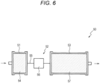
- FIG. 6 a reaction device 50 of a fourth embodiment will be described.
- the cases in which the low-activity catalyst 25, 45, and the inert body 35 are accommodated in the second section 22, 32, and 42, respectively, were described.
- the case in which a second section 52 is equipped with a pipe 55 will be described.
- the same members as described in the first embodiment are denoted by the same reference numerals, and overlapping description will be omitted.
- FIG. 6 is a cross-section of the reaction device 50 of the fourth embodiment.
- the reaction device 50 includes a first section 51, a second section 52, and a third section 53 in the source gas flow direction in that sequence.
- the first section 51 and the third section 53 accommodate catalyst 54, 57, respectively.
- the second section 52 is provided with the pipe 55 which connects the first section 51 with the third section 53, and a condenser 56 disposed around the pipe 55.
- the pressure in the first section 51 or the third section 53 is appropriately regulated, and the two sections are heated by means of a heater (not illustrated). No heater is disposed around the condenser 56.
- the source gas passes through the first section 51, the second section 52, and the third section 53 in that sequence, whereby a chemical reaction forming methane and water proceeds.
- the degree of lowering activation energy is smaller than that in the first section 51.
- the rate of reaction becomes smaller than that in the first section 51, resulting in a drop in temperature.
- the degree of lowering activation energy is greater than that in the second section 52, and the rate of reaction becomes greater than that in the second section 52, leading to a rise in temperature by heat of reaction.
- the condenser 56 is disposed around the pipe 55, but no heater is disposed around the condenser 56.
- the second section 52 can be more effectively cooled, as compared with the second sections 22, 32, and 42 of the first to third embodiments.
- the catalytic activity of the catalyst 54 in the first section 51 is equal to that of the catalyst 57 in the third section 53, or lower than that of the catalyst 57 in the third section 53.
- the thickness of the first section 51 in the source gas flow direction is smaller than that of the third section 53 in the source gas flow direction.
- the reaction product in the first section 51 is cooled to ice temperature, to thereby isolate water.
- steam supplied to the third section 53 via the second section 52 can be reduced, the rate of reaction in the third section 53 can increase.
- the cases in which the first section 21, 31, or 41, the second section 22, 32, or 42, and the third section 23, 33, or 43 have the same inner diameter were described.
- the inner diameter is not particularly limited thereto. Needless to say, the inner diameters of the first section 21, 31, or 41, the second section 22, 32, or 42, or the third section 23, 33, or 43 may be varied.
- the configuration is not particularly limited thereto.
- the heater may be disposed around the condenser 56.
- the condenser 56 may be omitted, since the rate of reaction in the second section 52 can be reduced as compared with the first section 51 or the third section 53 by connecting the first section 51 to the third section 53 via the pipe 55.
- the condenser 56 is disposed around the pipe 55 provided in the second section 52 .
- the configuration is not particularly limited thereto.
- a low-activity catalyst having a catalytic activity lower than that of the catalyst 54 or 57, or an inert body having no catalytic activity may be disposed around the pipe 55.
Landscapes
- Chemical & Material Sciences (AREA)
- Organic Chemistry (AREA)
- Chemical Kinetics & Catalysis (AREA)
- Engineering & Computer Science (AREA)
- General Chemical & Material Sciences (AREA)
- Oil, Petroleum & Natural Gas (AREA)
- Devices And Processes Conducted In The Presence Of Fluids And Solid Particles (AREA)
- Physical Or Chemical Processes And Apparatus (AREA)
Abstract
To provide a reaction device in which deterioration of a catalyst is suppressed and which can employ a short reaction vessel. A reaction device (10) in which an exothermic chemical reaction occurs, has a reaction vessel (20) through which a source gas passes from an inlet to an outlet, and catalysts (24, 26) accommodated in the reaction vessel. The reaction device includes a first section (21), a second section (22), and a third section (23) disposed in that sequence along the direction of flow of the source gas. Among the first, second, and third sections, the degree of lowering the activation energy of the chemical reaction is the smallest in the second section. In the reaction device, the temperature rises in the first section, lowers in the second section, and rises in the third section.
Description
- The present invention relates to a reaction device in which an exothermic chemical reaction is conducted.
- In a reaction device which has a reaction vessel including a catalyst and through which a source gas is caused to pass, resulting in chemical reaction accompanied by heat generation, the temperature of the reaction field rises by heat of reaction, whereby deterioration of the catalyst (e.g., sintering) readily occurs. Patent Literature 1 discloses a related technique for suppressing deterioration of such a catalyst. In the technique, source gases are caused to pass through a series of reaction vessels that are juxtaposed at specific intervals, and the gases are combined, to thereby reduce variation in temperature distribution in a cross-sectional direction of each reaction vessel. As a result, overheating of the catalyst is prevented.
- Patent Literature 1:
JP2018-114432A - In the related technique, reaction vessels are juxtaposed at specific intervals, and the total volume of the reaction vessels is smaller than the volume of the space in which the reaction vessels are disposed. When the total volume of reaction vessels commensurate with the volume of the space in which the reaction vessels are disposed is secured, the total path length of the reaction vessels problematically increases.
- The present invention has been accomplished to solve the above problem. Thus, an object of the present invention is to provide a reaction device which can achieve reduction of deterioration of a catalyst and shorten the path length of a reaction vessel.
- In a first aspect of the present invention so as to attain the above object, there is provided a reaction device in which an exothermic chemical reaction occurs, the reaction device having a reaction vessel through which a source gas passes from an inlet to an outlet, and a catalyst accommodated in the reaction vessel. The reactor includes a first section, a second section, and a third section disposed in that sequence along the direction of flow of the source gas. Among the first, second, and third sections, the degree of lowering the activation energy of the chemical reaction is the smallest in the second section.
- In a second aspect of the present invention, there is provided a reaction device in which an exothermic chemical reaction occurs, the reaction device having a reaction vessel through which a source gas passes from an inlet to an outlet, and a catalyst accommodated in the reaction vessel. The reactor includes a first section, a second section, and a third section disposed in that sequence along the direction of flow of the source gas. The temperature rises in the first section, lowers in the second section, and rises in the third section.
- A third aspect is directed to a specific embodiment of the first and second aspects, in which the second section accommodates an inert body having no catalytic activity or a low-activity catalyst having a catalytic activity lower than that of a catalyst accommodated in the first section or the third section.
- A fourth aspect is directed to a specific embodiment of any of the first to third aspects, in which the first section accommodates a catalyst having a catalytic activity lower than that of a catalyst accommodated in the third section.
- A fifth aspect is directed to a specific embodiment of any of the first to fourth aspects, in which the first section has a thickness in the gas flow direction smaller than the thickness of the third section in the gas flow direction.
- A sixth aspect is directed to a specific embodiment of any of the first to fifth aspects, in which the chemical reaction is a reaction of synthesizing methane from a source gas including hydrogen and carbon dioxide.
- The reaction device has a reaction vessel and a catalyst accommodated in the reaction vessel, and includes a first section, a second section, and a third section disposed in that sequence along the direction of flow of the source gas. Among the first, second, and third sections, the degree of lowering the activation energy of the chemical reaction is the smallest in the second section. Thus, heat generation in the second section is smaller than that in the first section or the third section. Since the temperature rose in the first section lowers in the second section, over-heating of the catalyst can be prevented, even the path length of a reaction vessel is short. As a result, deterioration of the catalyst can be suppressed.
- The reaction device has a reaction vessel and a catalyst accommodated in the reaction vessel, and includes a first section, a second section, and a third section disposed in that sequence along the direction of flow of the source gas. The temperature rises in the first section, lowers in the second section, and rises in the third section. Over-heating of the catalyst can be prevented, even the path length of a reaction vessel is short. As a result, deterioration of the catalyst can be suppressed.
-
- [
FIG. 1 ] A block diagram of a reaction device of a first embodiment. - [
FIG. 2 ] A cross-section of a reaction vessel. - [
FIG. 3 ] A graph showing a temperature in each section of the reaction device. - [
FIG. 4 ] A cross-section of a reaction device of a second embodiment. - [
FIG. 5 ] A cross-section of a reaction device of a third embodiment. - [
FIG. 6 ] A cross-section of a reaction device of a fourth embodiment. - With reference to the attached drawings, a preferred embodiments of the present invention will be described.
FIG. 1 is a block diagram of areaction device 10 of a first embodiment. Thereaction device 10 has areaction vessel 20 in which a source gas passes. Thereaction vessel 20 is connected to aconfluence pipe 17, to which twopipes pipe 11 is a pipe through which a first source gas is supplied, and acontrol valve 12 and acheck valve 13 are disposed in that sequence from the upstream side to the downstream side. Thepipe 14 is a pipe through which a second source gas is supplied, and acontrol valve 15 and acheck valve 16 are disposed in that sequence from the upstream side to the downstream side. Theconfluence pipe 17 is provided with agate valve 18. By means of thecontrol valves reaction vessel 20 via thegate valve 18. - The present embodiment corresponds to a case in which the first source gas is hydrogen, and the second source gas is carbon dioxide. The embodiment will be described. In the
reaction vessel 20, pressure is appropriately controlled, and the container is heated by means of aheater 27, whereby production of methane (i.e., methanation) represented by the chemical reaction formula: CO2 + 4H2 → CH4 + 2H2O is conducted. The product is cooled by means of acondenser 28 connected to a downstream side of thereaction vessel 20 to ice temperature. As a result, the product is separated into water and a methane-containing gas. The methane-containing gas may contain hydrogen and carbon dioxide serving as source gases. - Methanation is an example of the chemical reaction occurring in the
reaction device 10, and the chemical reaction is not limited thereto. By appropriately modifying the source gas, reaction conditions, and the catalyst (mentioned hereinbelow), for example, the following chemical reactions can be caused to be conducted in thereaction device 10. - Production of syngas via partial oxidation of methane: 2CH4 + O2 → 2CO + 4H2
- Methanol synthesis: CO + 2H2 → CH3OH
- Methanol synthesis: CO2 + 3H2 → CH3OH + H2O
- Fischer-Tropsch synthesis: CO + 2H2 → -(CH2)- + H2O (-(CH2)- represents a linear-chain hydrocarbon)
- Dimethyl ether synthesis: 2CO + 4H2 → CH3OCH3 + H2O
-
FIG. 2 is a cross-section of thereaction device 10. The arrows shown inFIG. 2 denote the flow direction of the source gas reaction in the container 20 (the same applies toFIGs. 4 to 6 ). Thereaction vessel 20 accommodatescatalysts activity catalyst 25. Thereaction device 10 includes afirst section 21, asecond section 22, and athird section 23 disposed in that sequence along the direction of flow of the source gas (upstream side to downstream side). Thefirst section 21 and thethird section 23 accommodate thecatalysts second section 22 accommodates the low-activity catalyst 25 having a catalytic activity lower than that of thecatalyst catalysts activity catalyst 25 lower the activation energy of chemical reaction, to thereby facilitate progress of the chemical reaction. A low catalytic activity refers to a small degree of lowering the activation energy of chemical reaction. - In the present embodiment, the
first section 21, thesecond section 22, and thethird section 23 are joined to one another by fastening flanges of tubes having the same inner diameter with bolts or the like, the tubes accommodating thecatalyst 24, the low-activity catalyst 25, and thecatalyst 26, respectively. However, the fastening manner is not limited thereto. Needless to say, alternatively, thecatalyst 24, the low-activity catalyst 25, and thecatalyst 26 may be sequentially charged to a single tube, to thereby provide thefirst section 21, thesecond section 22, and thethird section 23. - No particular limitation is imposed on the
catalysts activity catalyst 25 used in the embodiment, so long as the catalysts are adapted to various chemical reaction. Examples of thecatalysts activity catalyst 25 include powder, pellets, and a porous body of a particle-on-carrier. Examples of the carrier include powder, pellets, and a porous body of an oxide including one or more species of alumina, silica, magnesia, titania, zirconia, niobia, silica-alumina, zeolite, and calcium phosphate. The porous body has gas permeability which allows the source gas to pass through. In the case of powder or pellets, the source gas passes through voids therein. - Examples of the material of the particles supported on the carrier include metals including one or more elements of Fe, Co, Ni, Cu, Ru, Rh, Pd, Ag, Ir, Pt, and Au. Regarding the catalyst, if the same material and particle size of the carrier and particles are employed, catalytic activity increases in proportion to the surface area of the particles supported on the carrier. Thus, by reducing the surface area of the particles supported on the carrier with respect to that of the
catalysts activity catalyst 25 can be provided. - Also, when inert particles having no catalytic activity are added to the
catalyst catalyst activity catalyst 25 is provided. Examples of the inert particle species include powder and pellets of an oxide including one or more species of alumina, silica, magnesia, titania, zirconia, niobia, silica-alumina, zeolite, and calcium phosphate. - When a source gas including hydrogen and carbon dioxide is caused to pass through the
reaction vessel 20, the source gas passes through thefirst section 21, thesecond section 22, and thethird section 23 in that sequence, whereby a chemical reaction forming methane and water proceeds. -
FIG. 3 is a graph showing a change in temperature over the sections of thereaction device 10. An Example in relation toFIG. 3 corresponds to temperatures recorded at thefirst section 21, thesecond section 22, and thethird section 23. The temperatures are sensed by a plurality of thermocouples disposed in the source gas flow direction along the center axis penetrating the cross-sections of reaction field (catalyst present area) of the first to third sections. A Comparative Example corresponds to temperatures recorded in a similar manner, but thereaction device 10 is not segmented into thefirst section 21, thesecond section 22, and thethird section 23, and thecatalyst 24 of thefirst section 21 is disposed in the whole area of thereaction vessel 20. - As shown in
FIG. 3 , in the Example, the temperature rises in thefirst section 21, lowers in thesecond section 22, and rises in thethird section 23. In thesecond section 22, the catalytic activity of the low-activity catalyst 25 is lower than that of thecatalyst 24, and the degree of lowering activation energy is smaller than that in thefirst section 21. As a result, the reaction rate in thesecond section 22 is less than that in thefirst section 21, leading to a drop in temperature. In thethird section 23, the catalytic activity of theactivity catalyst 26 is higher than that of the low-activity catalyst 25, and the degree of lowering activation energy is greater than that in thesecond section 22. Thus, the rate of reaction becomes greater than that in thesecond section 22, leading to a rise in temperature by heat of reaction. However, since methane and steam (i.e., reaction products) are present in thethird section 23, heat of reaction in thethird section 23 does not considerably increase. Also, since thesecond section 22 intervenes between thethird section 23 and thefirst section 21, the heat in thethird section 23 is not easily transferred to thefirst section 21. As a result, the temperature in thefirst section 21 does not considerably rise. - In contrast, in the Comparative Example, the maximum arrival temperature of the reaction field by a chemical reaction forming methane and water from a source gas (exothermic reaction) is higher than that attained in the Example. In the Example, the temperatures of the
catalysts activity catalyst 25, which are elevated as the progress of chemical reaction, can be lowered, as compared with the Comparative Example, leading to reduction in deterioration of the catalysts. In addition, since juxtaposing reaction vessels at specific intervals as employed in the related art is not needed, the total pass length of thereaction vessel 20 can be reduced, while the volume of thereaction vessel 20 is secured. - The embodiment will be described with reference to
FIG.2 again. The catalytic activity of thecatalyst 24 in thefirst section 21 is equal to that of thecatalyst 26 in thethird section 23, or lower than that of thecatalyst 26 in thethird section 23. The thickness of thefirst section 21 in the source gas flow direction is smaller than that of thethird section 23 in the source gas flow direction. Thus, even when the catalytic activity of thecatalyst 24 in thefirst section 21 is equivalent to the catalytic activity of thecatalyst 26 in thethird section 23, the temperature of thefirst section 21 attributed to heat of reaction can be lowered, as compared with the case in which the thickness of thefirst section 21 is greater than that of thethird section 23. As a result, deterioration of thecatalyst 24 can be suppressed. If catalysts having the same catalytic activity are placed in thefirst section 21 and thethird section 23, respectively, twocatalysts - The thickness of the
second section 22 in the source gas flow direction is smaller than that of thethird section 23 in the source gas flow direction. Thus, the total path length of thereaction vessel 20 can be shortened, as compared with the case in which the thickness of thesecond section 22 is greater than that of thethird section 23. - The thickness of the
second section 22 in the source gas flow direction is greater than that of thefirst section 21 in the source gas flow direction. Thus, adiabatic property of low-activity catalyst 25 disposed between thefirst section 21 and thethird section 23 can be secured. - With reference to
FIG. 4 , areaction device 30 of a second embodiment will be described. In the first embodiment, the case in which the low-activity catalyst 25 is disposed in thesecond section 22 was described. However, in the second embodiment, the case in which aninert body 35 having no catalytic activity is disposed in asecond section 32 will be described. The same members as described in the first embodiment are denoted by the same reference numerals, and overlapping description will be omitted.FIG. 4 is a cross-section of thereaction device 30 of the second embodiment. - The
reaction device 30 includes afirst section 31, asecond section 32, and athird section 33 in the source gas flow direction in that sequence. Thereaction vessel 20 accommodatescatalysts inert body 35. Thefirst section 31 and thethird section 33 accommodate thecatalysts catalysts second section 32 accommodates theinert body 35 having no catalytic activity. The term "having no catalytic activity" refers to that theinert body 35 is impotent to reduce activation energy of chemical reaction. - Examples of the
inert body 35 include powder, pellets, and a porous body of an oxide including one or more species of alumina, silica, magnesia, titania, zirconia, niobia, silica-alumina, zeolite, and calcium phosphate. The porous body has gas permeability which allows the source gas to pass through. In the case of powder or pellets, the source gas passes through voids therein. - When a source gas formed by mixing hydrogen with carbon dioxide is caused to pass through the
reaction vessel 20, the source gas passes through thefirst section 31, thesecond section 32, and thethird section 33 in that sequence, whereby a chemical reaction forming methane and water proceeds. In thesecond section 32, theinert body 35 has no catalytic activity, and the degree of lowering activation energy is smaller than that in thefirst section 31. Thus, the rate of reaction becomes smaller than that in thefirst section 31, resulting in a drop in temperature. In thethird section 33, by virtue of the presence of thecatalyst 36, the degree of lowering activation energy is greater than that in thesecond section 32, and the rate of reaction becomes greater than that in thesecond section 32, leading to a rise in temperature by heat of reaction. However, since methane and steam are present in thethird section 33, heat of reaction in thethird section 33 does not considerably increase. Also, since thesecond section 32 intervenes between thethird section 33 and thefirst section 31, the heat in thethird section 33 is not easily transferred to thefirst section 31. As a result, the temperature in thefirst section 31 does not considerably rise. Thus, deterioration of thecatalysts - The catalytic activity of the
catalyst 34 in thefirst section 31 is equal to that of thecatalyst 36 in thethird section 33, or lower than that of thecatalyst 36 in thethird section 33. The thickness of thefirst section 31 in the source gas flow direction is smaller than that of thethird section 33 in the source gas flow direction. The thickness of thesecond section 32 in the source gas flow direction is smaller than that of thethird section 33 in the source gas flow direction. - The thickness of the
second section 32 in the source gas flow direction is smaller than that of thefirst section 31 in the source gas flow direction. Thus, the total path length of thereaction vessel 20 can be shortened, as compared with the case in which the thickness of thesecond section 32 is greater than that of thefirst section 31. - With reference to
FIG. 5 , areaction device 40 of a third embodiment will be described. In the first and second embodiments, the case in which the thickness of thefirst section third section first section 41 is equal to that of thethird section 43 will be described. The same members as described in the first embodiment are denoted by the same reference numerals, and overlapping description will be omitted.FIG. 5 is a cross-section of thereaction device 40 of the third embodiment. - The
reaction device 40 includes afirst section 41, asecond section 42, and athird section 43 in the source gas flow direction in that sequence. Thereaction vessel 20 accommodatescatalysts activity catalyst 45. Thefirst section 31 and thethird section 33 accommodate thecatalysts first section 41 and thethird section 43 accommodate thecatalysts catalyst 44 is lower than that of thecatalyst 46. Thesecond section 42 accommodate the low-activity catalyst 45 having a catalytic activity lower than that of thecatalyst - When a source gas formed by mixing hydrogen with carbon dioxide is caused to pass through the
reaction vessel 20, the source gas passes through thefirst section 41, thesecond section 42, and thethird section 43 in that sequence, whereby a chemical reaction forming methane and water proceeds. In thesecond section 42, the low-activity catalyst 45 has a catalytic activity lower than that of thecatalyst 44, and the degree of lowering activation energy is smaller than that in thefirst section 41. Thus, the rate of reaction becomes smaller than that in thefirst section 41, resulting in a drop in temperature. In thethird section 43, by virtue of the presence of thecatalyst 46, the degree of lowering activation energy is greater than that in thesecond section 42, and the rate of reaction becomes greater than that in thesecond section 42, leading to a rise in temperature by heat of reaction. However, since methane and steam are present in thethird section 43, heat of reaction in thethird section 43 does not considerably increase. Also, since thesecond section 42 intervenes between thethird section 43 and thefirst section 41, the heat in thethird section 43 is not easily transferred to thefirst section 41. As a result, the temperature in thefirst section 41 does not considerably rise. Thus, deterioration of thecatalysts activity catalyst 46 can be suppressed. - Although the thickness of the
first section 41 in the source gas flow direction is equal to that of thethird section 43 in the source gas flow direction, the catalytic activity of thecatalyst 44 in thefirst section 41 is lower than that of thecatalyst 46 in thethird section 43. Thus, an excessive increase in heat of reaction can be prevented in thefirst section 41. - With reference to
FIG. 6 , areaction device 50 of a fourth embodiment will be described. In the first to third embodiments, the cases in which the low-activity catalyst inert body 35 are accommodated in thesecond section second section 52 is equipped with apipe 55 will be described. The same members as described in the first embodiment are denoted by the same reference numerals, and overlapping description will be omitted.FIG. 6 is a cross-section of thereaction device 50 of the fourth embodiment. - The
reaction device 50 includes afirst section 51, asecond section 52, and athird section 53 in the source gas flow direction in that sequence. Thefirst section 51 and thethird section 53 accommodatecatalyst second section 52 is provided with thepipe 55 which connects thefirst section 51 with thethird section 53, and acondenser 56 disposed around thepipe 55. The pressure in thefirst section 51 or thethird section 53 is appropriately regulated, and the two sections are heated by means of a heater (not illustrated). No heater is disposed around thecondenser 56. - When a source gas formed by mixing hydrogen with carbon dioxide is supplied to the
first section 51, the source gas passes through thefirst section 51, thesecond section 52, and thethird section 53 in that sequence, whereby a chemical reaction forming methane and water proceeds. In thesecond section 52, no catalyst is present, and the degree of lowering activation energy is smaller than that in thefirst section 51. Thus, the rate of reaction becomes smaller than that in thefirst section 51, resulting in a drop in temperature. In thethird section 53, by virtue of the presence of thecatalyst 57, the degree of lowering activation energy is greater than that in thesecond section 52, and the rate of reaction becomes greater than that in thesecond section 52, leading to a rise in temperature by heat of reaction. However, since methane are present in thethird section 53, heat of reaction in thethird section 53 does not considerably increase. Also, since thesecond section 52 intervenes between thethird section 53 and thefirst section 51, the heat in thethird section 53 is not easily transferred to thefirst section 51. As a result, the temperature in thefirst section 51 does not considerably rise. Thus, deterioration of thecatalysts - Particularly, the
condenser 56 is disposed around thepipe 55, but no heater is disposed around thecondenser 56. Thus, thesecond section 52 can be more effectively cooled, as compared with thesecond sections - The catalytic activity of the
catalyst 54 in thefirst section 51 is equal to that of thecatalyst 57 in thethird section 53, or lower than that of thecatalyst 57 in thethird section 53. The thickness of thefirst section 51 in the source gas flow direction is smaller than that of thethird section 53 in the source gas flow direction. Thus, even when the catalytic activity of thecatalyst 54 in thefirst section 51 is equivalent to the catalytic activity of thecatalyst 57 in thethird section 53, the temperature of thefirst section 51 attributed to heat of reaction can be lowered, as compared with the case in which the thickness of thefirst section 51 is greater than that of thethird section 53. As a result, deterioration of thecatalyst 54 can be suppressed. - By means of the
condenser 56 disposed around thepipe 55 in thesecond section 52, the reaction product in thefirst section 51 is cooled to ice temperature, to thereby isolate water. Thus, since steam supplied to thethird section 53 via thesecond section 52 can be reduced, the rate of reaction in thethird section 53 can increase. - The present invention has been described on the basis of some embodiments. However, those skilled in the art can readily conceive that the present invention is not limited in any way to the aforementioned embodiments, and that various modifications and variations can be employed without deviating the scope of the present invention.
- In the above embodiments, the cases in which the
first section second section third section first section second section third section - In the fourth embodiment, the case in which no heater is disposed around the
condenser 56 provided in thesecond section 52 was described. However, the configuration is not particularly limited thereto. When thecondenser 56 has such high cooling capacity as to suppress a rise in temperature of thesecond section 52 caused by a heater, the heater may be disposed around thecondenser 56. - In the fourth embodiment, the case in which the
second section 52 has thecondenser 56 was described. However, the configuration is not particularly limited thereto. Needless to say, thecondenser 56 may be omitted, since the rate of reaction in thesecond section 52 can be reduced as compared with thefirst section 51 or thethird section 53 by connecting thefirst section 51 to thethird section 53 via thepipe 55. - In the fourth embodiment, the case in which the
condenser 56 is disposed around thepipe 55 provided in thesecond section 52 was described. However, the configuration is not particularly limited thereto. Needless to say, instead of thecondenser 56, a low-activity catalyst having a catalytic activity lower than that of thecatalyst pipe 55. -
- 10, 30, 40, 50 reaction device
- 20 reaction vessel
- 21, 31, 41, 51 first section
- 22, 32, 42, 52 second section
- 23, 33, 43, 53 third section
- 24, 26, 34, 36, 44, 46, 54, 57 catalyst
- 25, 45 low-activity catalyst
- 35 inert body
Claims (6)
- A reaction device in which an exothermic chemical reaction occurs, the reaction device having a reaction vessel through which a source gas passes from an inlet to an outlet, and a catalyst accommodated in the reaction vessel,wherein the reaction device includes a first section, a second section, and a third section disposed in that sequence along the direction of flow of the source gas; andamong the first, second, and third sections, the degree of lowering the activation energy of the chemical reaction is the smallest in the second section.
- A reaction device in which an exothermic chemical reaction occurs, the reaction device having a reaction vessel through which a source gas passes from an inlet to an outlet, and a catalyst accommodated in the reaction vessel,wherein the reaction device includes a first section, a second section, and a third section disposed in that sequence along the direction of flow of the source gas; andthe temperature rises in the first section, lowers in the second section, and rises in the third section.
- A reaction device according to claim 1,
wherein the second section accommodates an inert body having no catalytic activity or a low-activity catalyst having a catalytic activity lower than that of a catalyst accommodated in the first section or the third section. - A reaction device according to claim 1 or 3,
wherein
the first section accommodates a catalyst having a catalytic activity lower than that of a catalyst accommodated in the third section. - A reaction device according to claim 1 or 3,
wherein the first section has a thickness in the gas flow direction smaller than the thickness of the third section in the gas flow direction. - A reaction device according to claim 1 or 2,
wherein the chemical reaction is a reaction of synthesizing methane from the source gas including hydrogen and carbon dioxide.
Applications Claiming Priority (2)
| Application Number | Priority Date | Filing Date | Title |
|---|---|---|---|
| JP2022080745A JP7713907B2 (en) | 2022-05-17 | 2022-05-17 | Reactor |
| PCT/JP2023/016259 WO2023223783A1 (en) | 2022-05-17 | 2023-04-25 | Reaction device |
Publications (1)
| Publication Number | Publication Date |
|---|---|
| EP4527825A1 true EP4527825A1 (en) | 2025-03-26 |
Family
ID=88835027
Family Applications (1)
| Application Number | Title | Priority Date | Filing Date |
|---|---|---|---|
| EP23807394.4A Pending EP4527825A1 (en) | 2022-05-17 | 2023-04-25 | Reaction device |
Country Status (5)
| Country | Link |
|---|---|
| US (1) | US20250214052A1 (en) |
| EP (1) | EP4527825A1 (en) |
| JP (1) | JP7713907B2 (en) |
| CN (1) | CN118973698A (en) |
| WO (1) | WO2023223783A1 (en) |
Families Citing this family (1)
| Publication number | Priority date | Publication date | Assignee | Title |
|---|---|---|---|---|
| US12325674B1 (en) * | 2024-03-15 | 2025-06-10 | General Galactic Technologies Corporation | Modular system for renewable fuel generation |
Family Cites Families (5)
| Publication number | Priority date | Publication date | Assignee | Title |
|---|---|---|---|---|
| JPS5929679A (en) * | 1982-08-02 | 1984-02-16 | アモコ・コ−ポレ−ション | Manufacture of maleic acid anhydride |
| JP2002143675A (en) * | 2000-09-04 | 2002-05-21 | Kawasaki Heavy Ind Ltd | Reactor, catalyst used in the reactor and method for producing the same |
| EP1852413A1 (en) * | 2006-04-27 | 2007-11-07 | Basf Aktiengesellschaft | Process for gas phase oxidation with the use of a moderator layer |
| JP6263029B2 (en) * | 2013-12-27 | 2018-01-17 | 株式会社日立製作所 | Methane production method, methane production apparatus, and gasification system using the same |
| JP6848456B2 (en) | 2017-01-16 | 2021-03-24 | 株式会社Ihi | Reactor |
-
2022
- 2022-05-17 JP JP2022080745A patent/JP7713907B2/en active Active
-
2023
- 2023-04-25 EP EP23807394.4A patent/EP4527825A1/en active Pending
- 2023-04-25 US US18/851,815 patent/US20250214052A1/en active Pending
- 2023-04-25 CN CN202380031400.6A patent/CN118973698A/en active Pending
- 2023-04-25 WO PCT/JP2023/016259 patent/WO2023223783A1/en not_active Ceased
Also Published As
| Publication number | Publication date |
|---|---|
| WO2023223783A1 (en) | 2023-11-23 |
| US20250214052A1 (en) | 2025-07-03 |
| JP7713907B2 (en) | 2025-07-28 |
| JP2023169563A (en) | 2023-11-30 |
| CN118973698A (en) | 2024-11-15 |
Similar Documents
| Publication | Publication Date | Title |
|---|---|---|
| US20080028680A1 (en) | Process to Prepare Synthesis Gas | |
| US8591861B2 (en) | Hydrogenating pre-reformer in synthesis gas production processes | |
| KR20200096755A (en) | Methods and systems for synthesis gas production | |
| US20170226029A1 (en) | Methods of producing ethylene and synthesis gas by combining the oxidative coupling of methane and dry reforming of methane reactions | |
| US20040014826A1 (en) | Reactor for temperature moderation | |
| MX2012013556A (en) | Process for the preparation of synthesis gas. | |
| KR20220024005A (en) | catalyst regeneration | |
| US20190282986A1 (en) | Synthesis gas reactor tubes and reactors and related systems and processes | |
| US20250214052A1 (en) | Reaction device | |
| JP2020124665A (en) | Gas-phase reaction catalytic reactor and catalytic reaction method | |
| US7416571B2 (en) | Compact mixer for the mixing of gaseous hydrocarbon and gaseous oxidants | |
| US7008560B2 (en) | Silicon carbide-supported catalysts for partial oxidation of natural gas to synthesis gas | |
| JP5641693B2 (en) | Process for the production of condensed phase products from one or more gas phase reactants | |
| CN105682785B (en) | Method and reactor for exothermic reaction | |
| EP4674525A1 (en) | Reactor | |
| WO2006045744A1 (en) | Process for steam and/or co2 reforming of a hydrocarbonaceous feedstock | |
| RU2796425C1 (en) | Synthesis gas reactor and method for producing synthesis gas in synthesis gas reactor | |
| US7491380B2 (en) | Catalytic reactor | |
| US20210221758A1 (en) | A process for methanol production using a low-iron catalyst | |
| GB2588199A (en) | Regeneration of catalyst |
Legal Events
| Date | Code | Title | Description |
|---|---|---|---|
| STAA | Information on the status of an ep patent application or granted ep patent |
Free format text: STATUS: THE INTERNATIONAL PUBLICATION HAS BEEN MADE |
|
| PUAI | Public reference made under article 153(3) epc to a published international application that has entered the european phase |
Free format text: ORIGINAL CODE: 0009012 |
|
| STAA | Information on the status of an ep patent application or granted ep patent |
Free format text: STATUS: REQUEST FOR EXAMINATION WAS MADE |
|
| 17P | Request for examination filed |
Effective date: 20240927 |
|
| AK | Designated contracting states |
Kind code of ref document: A1 Designated state(s): AL AT BE BG CH CY CZ DE DK EE ES FI FR GB GR HR HU IE IS IT LI LT LU LV MC ME MK MT NL NO PL PT RO RS SE SI SK SM TR |
|
| DAV | Request for validation of the european patent (deleted) | ||
| DAX | Request for extension of the european patent (deleted) |