EP4527769A1 - Magazine unit for a packaging machine, packaging machine having a magazine unit and method for loading a magazine unit - Google Patents
Magazine unit for a packaging machine, packaging machine having a magazine unit and method for loading a magazine unit Download PDFInfo
- Publication number
- EP4527769A1 EP4527769A1 EP24200472.9A EP24200472A EP4527769A1 EP 4527769 A1 EP4527769 A1 EP 4527769A1 EP 24200472 A EP24200472 A EP 24200472A EP 4527769 A1 EP4527769 A1 EP 4527769A1
- Authority
- EP
- European Patent Office
- Prior art keywords
- housing
- magazine unit
- spindle
- housing seat
- angular position
- Prior art date
- Legal status (The legal status is an assumption and is not a legal conclusion. Google has not performed a legal analysis and makes no representation as to the accuracy of the status listed.)
- Pending
Links
Images



Classifications
-
- B—PERFORMING OPERATIONS; TRANSPORTING
- B65—CONVEYING; PACKING; STORING; HANDLING THIN OR FILAMENTARY MATERIAL
- B65H—HANDLING THIN OR FILAMENTARY MATERIAL, e.g. SHEETS, WEBS, CABLES
- B65H19/00—Changing the web roll
- B65H19/10—Changing the web roll in unwinding mechanisms or in connection with unwinding operations
- B65H19/12—Lifting, transporting, or inserting the web roll; Removing empty core
- B65H19/126—Lifting, transporting, or inserting the web roll; Removing empty core with both-ends supporting arrangements
-
- B—PERFORMING OPERATIONS; TRANSPORTING
- B65—CONVEYING; PACKING; STORING; HANDLING THIN OR FILAMENTARY MATERIAL
- B65H—HANDLING THIN OR FILAMENTARY MATERIAL, e.g. SHEETS, WEBS, CABLES
- B65H16/00—Unwinding, paying-out webs
- B65H16/02—Supporting web roll
- B65H16/06—Supporting web roll both-ends type
-
- B—PERFORMING OPERATIONS; TRANSPORTING
- B65—CONVEYING; PACKING; STORING; HANDLING THIN OR FILAMENTARY MATERIAL
- B65B—MACHINES, APPARATUS OR DEVICES FOR, OR METHODS OF, PACKAGING ARTICLES OR MATERIALS; UNPACKING
- B65B41/00—Supplying or feeding container-forming sheets or wrapping material
- B65B41/12—Feeding webs from rolls
-
- B—PERFORMING OPERATIONS; TRANSPORTING
- B65—CONVEYING; PACKING; STORING; HANDLING THIN OR FILAMENTARY MATERIAL
- B65B—MACHINES, APPARATUS OR DEVICES FOR, OR METHODS OF, PACKAGING ARTICLES OR MATERIALS; UNPACKING
- B65B9/00—Enclosing successive articles, or quantities of material, e.g. liquids or semiliquids, in flat, folded, or tubular webs of flexible sheet material; Subdividing filled flexible tubes to form packages
- B65B9/10—Enclosing successive articles, or quantities of material, in preformed tubular webs, or in webs formed into tubes around filling nozzles, e.g. extruded tubular webs
- B65B9/12—Subdividing filled tubes to form two or more packages by sealing or securing involving displacement of contents
-
- B—PERFORMING OPERATIONS; TRANSPORTING
- B65—CONVEYING; PACKING; STORING; HANDLING THIN OR FILAMENTARY MATERIAL
- B65H—HANDLING THIN OR FILAMENTARY MATERIAL, e.g. SHEETS, WEBS, CABLES
- B65H2301/00—Handling processes for sheets or webs
- B65H2301/40—Type of handling process
- B65H2301/41—Winding, unwinding
- B65H2301/413—Supporting web roll
- B65H2301/4134—Both ends type arrangement
- B65H2301/41342—Both ends type arrangement shaft transversing the roll
- B65H2301/41344—Both ends type arrangement shaft transversing the roll the roll being fixed to the shaft (e.g. by clamping)
-
- B—PERFORMING OPERATIONS; TRANSPORTING
- B65—CONVEYING; PACKING; STORING; HANDLING THIN OR FILAMENTARY MATERIAL
- B65H—HANDLING THIN OR FILAMENTARY MATERIAL, e.g. SHEETS, WEBS, CABLES
- B65H2301/00—Handling processes for sheets or webs
- B65H2301/40—Type of handling process
- B65H2301/41—Winding, unwinding
- B65H2301/417—Handling or changing web rolls
- B65H2301/4171—Handling web roll
- B65H2301/4173—Handling web roll by central portion, e.g. gripping central portion
- B65H2301/41734—Handling web roll by central portion, e.g. gripping central portion involving rail
-
- B—PERFORMING OPERATIONS; TRANSPORTING
- B65—CONVEYING; PACKING; STORING; HANDLING THIN OR FILAMENTARY MATERIAL
- B65H—HANDLING THIN OR FILAMENTARY MATERIAL, e.g. SHEETS, WEBS, CABLES
- B65H2513/00—Dynamic entities; Timing aspects
- B65H2513/50—Timing
- B65H2513/51—Sequence of process
-
- B—PERFORMING OPERATIONS; TRANSPORTING
- B65—CONVEYING; PACKING; STORING; HANDLING THIN OR FILAMENTARY MATERIAL
- B65H—HANDLING THIN OR FILAMENTARY MATERIAL, e.g. SHEETS, WEBS, CABLES
- B65H2801/00—Application field
- B65H2801/69—Form fill-and-seal machines
Definitions
- the present invention also relates to a packaging machine, in particular a packaging machine for producing packages of a pourable product, more particular of a pourable food product, having a magazine unit.
- the present invention also relates to a method for loading a magazine unit of a packaging machine.
- liquid or pourable food products such as fruit juice, UHT (ultra-high-temperature treated) milk, wine, tomato sauce, etc.
- UHT ultra-high-temperature treated milk
- wine tomato sauce
- etc. are sold in packages made of sterilized packaging material.
- a typical example is the parallelepiped-shaped package for liquid or pourable food products known as Tetra Brik Aseptic (registered trademark), which is made by sealing and folding laminated strip packaging material.
- the packaging material has a multilayer structure comprising a base layer, e.g. of paper, covered on both sides with layers of heat-seal plastic material, e.g. polyethylene.
- the packaging material also comprises a layer of oxygen-barrier material (an oxygen-barrier layer), e.g. an aluminum foil, which is superimposed on a layer of heat-seal plastic material, and is in turn covered with another layer of heat-seal plastic material forming the inner face of the package eventually contacting the food product.
- Packages of this sort are normally produced on fully automatic packaging machines, which advance a web of packaging material through a sterilization apparatus for sterilizing the web of packaging material at a sterilization station and to an isolation chamber (a closed and sterile environment) in which the sterilized web of packaging material is maintained and advanced.
- an isolation chamber a closed and sterile environment
- the web of packaging material is folded and sealed longitudinally at a tube forming station to form a tube having a longitudinal seam portion, the tube being further fed along a vertical advancing direction.
- the tube is filled with a pourable product, in particular a pourable food product, and is transversally sealed and subsequently cut along equally spaced transversal cross sections within a package forming apparatus of the packaging machine during advancement along the vertical advancing direction.
- a pourable product in particular a pourable food product
- Pillow packages are so obtained, each pillow package having a longitudinal sealing band, a top transversal sealing band and a bottom transversal sealing band.
- a typical packaging machine comprises a magazine unit for hosting the web of packaging material, a conveying device for advancing the web of packaging material along a web advancement path and the tube formed from the web of packaging material along a tube advancement path, the sterilizing apparatus for sterilizing the web of packaging material prior to its formation into the tube, a tube forming and sealing device at least partially arranged within the isolation chamber and being configured to form the tube from the advancing web of packaging material and to longitudinally seal the tube, a filling device for filling the tube with the pourable product and the package forming apparatus adapted to form, transversally seal and cut individual packages from the tube of packaging material.
- a typical magazine unit comprises at least one support device configured to carry a spindle carrying a wound-up web of packaging material.
- each support device comprises a pair of housing seats, each of which holding an end portion of the spindle.
- each housing seat can be controlled between a receiving configuration in which the spindle is inserted into or removed from the respective housing seats, and an operative configuration in which the spindle is secured to, i.e. cannot exit from, the respective housing seats.
- an operator needs to guide the spindle into the respective housing seats, which are set in the respective receiving configurations.
- the operator must close the magazine unit and only then the operator can remotely set the housing seats in the operative configurations. Then, the operator can newly open the magazine unit so as to prepare the web of packaging material wound around the respective spindle.
- a magazine unit comprises two support devices.
- One of the support devices supports the spindle that holds the web of packaging material in use and the other support device supports the spindle that holds the web of packaging material that needs to be spliced to the web of packaging material in use before the web of packaging material in use is completely exhausted.
- Figure 4 shows a further detail of the portion of Figure 2 , with parts removed for clarity.
- Number 1 indicates as a whole a packaging machine for producing sealed packages 2 of a pourable product, in particular a pourable food product, such as milk, milk drinks, yoghurt, yoghurt drinks, fruit juice, wine, tomato sauce, emulsions, beverages containing pulp, salt, sugar, etc.
- a pourable food product such as milk, milk drinks, yoghurt, yoghurt drinks, fruit juice, wine, tomato sauce, emulsions, beverages containing pulp, salt, sugar, etc.
- packaging machine 1 may be configured to produce packages 2 from a web of packaging material 3, preferentially a web of multilayer packaging material.
- web of packaging material 3 may have heat seal properties (i.e. portions of the multilayer packaging material can be sealed to one another).
- web of packaging material 3 may comprise at least one layer of fibrous material, such as e.g. paper or cardboard, and at least two layers of heat-seal plastic material, e.g. polyethylene, interposing the layer of fibrous material in between one another. Preferentially, one of these two layers of heat-seal plastic material may define the inner face of packages 2 contacting the pourable product.
- fibrous material such as e.g. paper or cardboard
- heat-seal plastic material e.g. polyethylene
- web of packaging material 3 may also comprise a layer of gas- and light-barrier material, e.g. aluminum foil or ethylene vinyl alcohol (EVOH) film, preferentially being arranged between one of the layers of the heat-seal plastic material and the layer of fibrous material.
- gas- and light-barrier material e.g. aluminum foil or ethylene vinyl alcohol (EVOH) film
- web of packaging material 3 may also comprise a further layer of heat-seal plastic material being interposed between the layer of gas- and light-barrier material and the layer of fibrous material.
- web of packaging material 3 may comprise successively arranged patterns, each pattern defining a final graphical pattern of the respective package 2.
- packaging machine 1 operates, in use, such to guarantee that each package 2 comprises the respective pattern.
- packaging machine 1 may be configured to produce packages 2 by forming a tube 4 from web of packaging material 3, longitudinally sealing tube 4, filling tube 4 with the pourable product and to transversally seal, and preferentially transversally cut tube 4.
- each package 2 may extend along a longitudinal axis.
- each package 2 may comprise at least a first transversal sealing band arranged at a first end of package 2, and preferentially also a second transversal sealing band arranged at a second end of package 2 opposite to the first end.
- packaging machine 1 may comprise:
- conveying device 13 may be configured to advance web of packaging material 3 to a tube forming station, at which, in use, web of packaging material 3 is formed into tube 4. Conveying device 13 may also be configured to advance tube 4 along a tube advancement path Q.
- packaging machine 1 may also comprise:
- packaging machine 1 may also comprise an isolation chamber 18, preferentially delimiting an inner environment 19 from an outer environment 20.
- inner environment 19 may be a sterile environment, preferably containing a controlled atmosphere.
- tube forming and sealing device 15 may be at least partially arranged within and configured to fold and longitudinally seal tube 4 within isolation chamber 18, preferentially inner environment 19.
- packaging machine 1 may also comprise a sterilizing unit configured to sterilize the, in use, advancing web of packaging material 3, preferentially the sterilization unit being arranged upstream of tube forming and sealing device 15 along web advancement path P and/or downstream of host station 12.
- conveying device 13 may be configured to advance tube 4 and any intermediates of tube 4 along tube advancement path Q, preferentially from tube forming and sealing device 15 to and/or at least partially within package forming unit 17.
- any configuration of web of packaging material 3 is meant prior to obtaining the tube structure and after folding of web of packaging material 3 by tube forming and sealing device 15 has started.
- the intermediates of tube 4 are a result of the gradual folding of web of packaging material 3 so as to obtain tube 4, preferentially by overlapping the (longitudinal) edges of web of packaging material 3 with one another.
- tube forming and sealing device 15 may be arranged such that tube 4 may have a vertical orientation.
- filling device 16 may comprise a filling pipe being configured to direct, in use, the pourable product into tube 4.
- the filling pipe may, in use, be at least partially placed within tube 4 for feeding, in use, the pourable product into tube 4.
- package forming unit 17 may comprise a plurality of operative devices, each one configured to manipulate, preferentially to at least partially form, to at least transversally seal and to transversally cut, tube 4 for obtaining packages 2.
- magazine unit 10 may be arranged upstream of isolation chamber 18 and/or tube forming and sealing device 15 and/or packaging forming unit 17.
- magazine unit 10 comprises one or more support devices 25, each one configured to rotatably carry at least one reel 11.
- each reel 11, more precisely the respective web of packaging material 3, is illustrated as a transparent element so as to show (i.e. allow the reader to see) portions of magazine unit 10.
- each reel 11, more precisely the respective web of packaging material 3, is not transparent.
- Magazine unit 10 may comprise at least two support devices 25, arranged next to one another. More specifically, support devices 25 are arranged such to allow for arranging reels 11 within magazine unit 10 in parallel and next to one another.
- each reel 11 may comprise a spindle 26 and web of packaging material 3 being wound about spindle 26.
- spindle 26 may extend along a center axis.
- spindle 26 may comprise a first end portion 27 and a second end portion (not visible) opposite to first end portion 27.
- each spindle 26 may comprise a clamping group 29 (only partially shown) configured to clamp reel 11 on spindle 26.
- magazine unit 10 may comprise an inlet opening configured to allow for the introduction of reels 11 into magazine unit 10. Additionally, the inlet opening may allow for the removal of an exhausted reel 11 from magazine unit 10.
- the inlet opening may have a size allowing for an operator to at least partially enter magazine unit 10.
- magazine unit 10 may comprise a door movable between an open position in which the door opens the inlet opening and a closed position in which the door closes the inlet opening.
- each support device 25 comprises:
- each pair may be arranged side-by-side and may be distanced from the inlet opening. Even more specifically, each pair of housing seats 30 may be distanced from one another along a first direction D1.
- Each pair of housing seats 30 may rotatably carry the respective spindle 26 (for rotatably carrying the respective reel 11).
- each spindle 26 (and therewith also the respective reel 11) may be rotatable about the respective center axis, when being placed within the respective housing seats 30.
- second direction D2 may be transversal, more specifically (substantially) perpendicular to, first direction D1.
- one housing seat 30 of each pair may be configured to receive the respective first end portion 27 and the other housing seat 30 of the respective pair may be configured to receive the respective second end portion.
- the respective housing seats 30 of each pair may be configured to arrange the respective spindle 26 along a horizontal direction.
- respective guide rails 32 of each pair 31 may be arranged side-by-side.
- each guide rail 32 may extend to one respective housing seat 30.
- each pair 31 of guide rails 32 may be configured to guide the respective spindle 26 to, and in particular also into, the respective pair of housing seats 30.
- each guide rail 32 may extend from the respective inlet opening to the respective housing seat 30.
- one guide rail 32 of each pair 31 may be configured to be engaged by the respective first end portion 27 and the other guide rail 32 of the respective pair 31 may be configured to be engaged by the respective second end portion.
- the respective spindle 26 is placed on the respective guide rails 32 and is rolled over the respective guide rails 32 towards and to the respective housing seats 30.
- Each housing seat 30 is controllable in:
- each housing seat 30 is controllable in a respective intermediate configuration (distinct from the open configuration and the closed configuration) in which the housing seat is only partially closed, and in particular configured to impede the respective end portion (first end portion 27 or second end portion) of the respective spindle 26 to return onto the respective guide rail 32.
- packaging machine 1 and/or magazine unit 10 may comprise a control unit configured to at least control housing seats 30 between the respective opening configurations, intermediate configurations and closed configurations.
- control unit may be configured to move the housing seats 30 at first from the respective open configuration to the respective intermediate configuration and then from the respective intermediate configuration to the respective closed configuration.
- control unit may be configured to control housing seats 30 directly from the closed configuration to the open configuration or, alternatively, from the closed configuration to the intermediate configuration and then to the open configuration.
- control unit may be configured to simultaneously move the respective housing seats 30 of the respective pair from the respective open configurations to the respective intermediate configurations and from the respective intermediate configurations to the respective closed configurations.
- control unit may be configured to control housing seats 30 from the respective intermediate configurations to the respective closed configurations only in the case that the door of magazine unit 10 is in the closed position.
- magazine unit 10 may further comprise one or more actuation devices 33, such as a linear motor, configured to control housing seats 30 between the respective open configurations, the respective intermediate configurations and the respective closed configurations.
- actuation devices 33 such as a linear motor
- magazine unit 10 comprises one respective actuation device 33 for each housing seat 30 and each actuation device 33 may be coupled to the respective housing seat 30.
- control unit may be operatively connected to each actuation device 33 and may be configured to selectively control actuation devices 33 so as to control housing seats 30.
- each housing seat 30 may be rotatable around a respective rotation axis C.
- each housing seat 30 may be arranged in a first angular position (see Figure 3A ), a second angular position (see Figure 3B ) and a third angular position (see Figure 3C ) with respect to the respective rotation axis C when being controlled in, respectively, the respective open configuration, the respective intermediate configuration and the respective closed configuration.
- each second angular position is different from the respective first angular position and each third angular position is different from the respective first angular position and the respective second angular position.
- each actuation device 33 may be configured to rotate the respective housing seat(s) 30 in an angular direction from the respective first angular position to the respective second angular position and from the respective second angular position to the respective third angular position.
- Each second angular position is interposed between the respective first angular position and the respective third angular position with respect to the angular direction.
- each guide rail 32 may have a guide surface 34 configured to support spindle 26, more specifically one of the respective first end portion 27 and the respective second end portion.
- Each guide surface 34 extend from a first terminal portion 35 to a second terminal portion 36.
- each second terminal portion 36 may be adjacent to one respective housing seat 30.
- each first terminal portion 35 may be positioned adjacently to the inlet opening.
- each housing seat 30 may comprise a housing channel 40.
- each housing seat 30, in particular the respective housing channel 40 may comprise an inlet aperture 41 configured to allow for introducing the respective end portion of spindle 26 into and discharging the respective end portion of spindle 26 from the respective housing seat 30, in particular the respective housing channel 40.
- housing channel 40 is angularly movable about the respective rotation axis C. More specifically, housing channel 40 can be selectively positioned in the respective first angular position, the respective second angular position and the respective third angular position by operation of actuation device 33.
- each housing channel 40 may comprise an engagement surface 42 configured to guide the respective spindle 26, in particular the respective first end portion 27 or the respective second end portion into housing channel 40 and out of housing channel 40.
- each inlet aperture 41 and/or each engagement surface 42 and the respective second terminal portion 36 may be aligned with respect to one another with the respective housing seat 30 being in the open configuration (see Figure 3A ) and may be unaligned with respect to one another with the respective housing seat 30 being in the respective intermediate configuration (see Figure 3B ) and in the respective closed configuration (see Figure 3C ).
- each engagement surface 42 may be flush with the respective guide surface 34 with the respective housing seat 30 being in the open configuration (see Figure 3A ).
- each housing seat 30 and the respective guide rail 32 may be separated from one another by means of a respective edge 43 originating from positioning of housing seat 30 in the respective intermediate configuration (see Figure 3B ).
- each edge 43 may be substantially defined by controlling the respective housing seat 30 in the respective intermediate configuration.
- each housing channel 40 may comprise an abutment surface 44 opposite to the respective inlet aperture 41 and the respective end portion (first end portion 27 or second end portion) of the respective spindle 26 abuts against the abutment surface 44 when being arranged in housing seat 30.
- magazine unit 10 may also comprise a pair of support structures 45, each support structure 45 being configured to carry, in particular to rotatably carry, one respective housing seat 30.
- each support structure 45 may comprise a housing space and the respective housing seat 30 being rotatably movable within the respective housing space.
- each support structure 45 may comprise a plurality of bearing elements 47 (e.g. ball elements or roller elements or the like) arranged within the respective housing space and carrying the respective housing seat 30.
- bearing elements 47 e.g. ball elements or roller elements or the like
- each support structure 45 may also comprise a wall 48, in particular at least partially delimiting the respective housing space.
- each wall 48 may be arranged and/or designed such to close the respective inlet aperture 41 with the respective housing seat 30 being in the respective closed configuration.
- wall 48 guarantees that the respective end portion of spindle 26 cannot exit through the respective inlet aperture 41.
- each wall 48 may be arranged and/or designed such to partially close the respective inlet aperture 41 with the respective housing seat 30 being in the respective intermediate configuration.
- control unit may be configured to control each housing seat 30 after having received the respective end portion (either first end portion 27 or second end portion) of the respective spindle 26 from the open configuration to the intermediate configuration and afterwards from the intermediate configuration to the closed configuration.
- control unit may be configured to control each housing seat 30 from the respective intermediate configuration to the closed configuration only with the door of magazine unit 10 being closed.
- packaging machine 1 forms packages 2 filled with the pourable product.
- conveying device 13 advances web of packaging material 3 from magazine unit 10, preferentially to host station 12.
- conveying device advances web of packaging material 3 from host station 7 to forming station 10 at which web of packaging material 3 is formed into tube 4.
- Conveying device 13 further advances tube 4 along tube advancement path Q to package forming unit 17.
- filling device 16 fills tube 4 with the pourable product.
- web of packaging material 3 is sterilized at the sterilization station.
- each reel 11 gets exhausted.
- a new web of packaging material 3 is spliced to web of packaging material 3 in use.
- control unit commands actuation device(s) 33 so as to set the respective housing seats 30 in the respective second angular positions.
Landscapes
- Containers And Plastic Fillers For Packaging (AREA)
- Basic Packing Technique (AREA)
Abstract
There is described a magazine unit (10) for a packaging machine (1) comprising an inlet opening configured to allow for the introduction of a reel (11) having a spindle (26) carrying a wound-up web of packaging material (3) into the magazine unit (10), at least one pair of housing seats (30) configured to rotatably support the spindle (26) carrying the wound-up web of packaging material (3), the respective housing seats (30) being arranged side-by-side and distanced from the inlet opening. Each housing seat (30) is controllable in an open configuration in which the housing seat (30) is configured to receive a respective end portion (27) of the spindle (26), a closed configuration in which the housing seat (30) is fully closed and configured to lock the respective end portion (27) of the spindle (26) within the housing seat (30) and an intermediate configuration in which the housing seat (30) is only partially closed.
Description
- The present invention relates to a magazine unit for a packaging machine, preferentially a packaging machine configured to form packages from a web of packaging material.
- The present invention also relates to a packaging machine, in particular a packaging machine for producing packages of a pourable product, more particular of a pourable food product, having a magazine unit.
- Advantageously, the present invention also relates to a method for loading a magazine unit of a packaging machine.
- As is known, many liquid or pourable food products, such as fruit juice, UHT (ultra-high-temperature treated) milk, wine, tomato sauce, etc., are sold in packages made of sterilized packaging material.
- A typical example is the parallelepiped-shaped package for liquid or pourable food products known as Tetra Brik Aseptic (registered trademark), which is made by sealing and folding laminated strip packaging material. The packaging material has a multilayer structure comprising a base layer, e.g. of paper, covered on both sides with layers of heat-seal plastic material, e.g. polyethylene. In the case of aseptic packages for long-storage products, such as UHT milk, the packaging material also comprises a layer of oxygen-barrier material (an oxygen-barrier layer), e.g. an aluminum foil, which is superimposed on a layer of heat-seal plastic material, and is in turn covered with another layer of heat-seal plastic material forming the inner face of the package eventually contacting the food product.
- Packages of this sort are normally produced on fully automatic packaging machines, which advance a web of packaging material through a sterilization apparatus for sterilizing the web of packaging material at a sterilization station and to an isolation chamber (a closed and sterile environment) in which the sterilized web of packaging material is maintained and advanced. During advancement of the web of packaging material through the isolation chamber, the web of packaging material is folded and sealed longitudinally at a tube forming station to form a tube having a longitudinal seam portion, the tube being further fed along a vertical advancing direction.
- For completing the forming operations, the tube is filled with a pourable product, in particular a pourable food product, and is transversally sealed and subsequently cut along equally spaced transversal cross sections within a package forming apparatus of the packaging machine during advancement along the vertical advancing direction.
- Pillow packages are so obtained, each pillow package having a longitudinal sealing band, a top transversal sealing band and a bottom transversal sealing band.
- A typical packaging machine comprises a magazine unit for hosting the web of packaging material, a conveying device for advancing the web of packaging material along a web advancement path and the tube formed from the web of packaging material along a tube advancement path, the sterilizing apparatus for sterilizing the web of packaging material prior to its formation into the tube, a tube forming and sealing device at least partially arranged within the isolation chamber and being configured to form the tube from the advancing web of packaging material and to longitudinally seal the tube, a filling device for filling the tube with the pourable product and the package forming apparatus adapted to form, transversally seal and cut individual packages from the tube of packaging material.
- A typical magazine unit comprises at least one support device configured to carry a spindle carrying a wound-up web of packaging material.
- Moreover, each support device comprises a pair of housing seats, each of which holding an end portion of the spindle. Additionally, each housing seat can be controlled between a receiving configuration in which the spindle is inserted into or removed from the respective housing seats, and an operative configuration in which the spindle is secured to, i.e. cannot exit from, the respective housing seats. During a loading step, an operator needs to guide the spindle into the respective housing seats, which are set in the respective receiving configurations. Afterwards, for safety reasons the operator must close the magazine unit and only then the operator can remotely set the housing seats in the operative configurations. Then, the operator can newly open the magazine unit so as to prepare the web of packaging material wound around the respective spindle.
- Typically, a magazine unit comprises two support devices. One of the support devices supports the spindle that holds the web of packaging material in use and the other support device supports the spindle that holds the web of packaging material that needs to be spliced to the web of packaging material in use before the web of packaging material in use is completely exhausted.
- During a normal operation, the loading and the unloading of the spindles is repeated.
- Even though the known solutions work satisfactorily well, a desired is felt in the sector to further improve the support devices, in particular so as to facilitate the coupling and uncoupling of spindles (each carrying a reel of packaging material) to the support device.
- It is therefore an object of the present invention to provide an improved magazine unit, in particular a magazine unit which allows to easily load a spindle into the magazine unit.
- It is a further object of the present invention to provide an improved packaging machine having a magazine unit.
- It is a further object of the present invention to provide an improved method for loading a magazine unit.
- According to the present invention, there is provided a magazine unit according to
claim 1. - Preferred embodiments are claimed in the dependent claims.
- According to the present invention, there is also provided a packaging machine according to
claim 12. - According to the present invention, there is also provided a method according to any one of
claims 13 to 15. - A non-limiting embodiment of the present invention will be described by way of example with reference to the accompanying drawings, in which:
-
Figure 1 is a schematic view of a packaging machine for packaging a pourable product, with parts removed for clarity; -
Figure 2 is a lateral view of a portion of the packaging machine ofFigure 1 , with parts removed for clarity; -
Figures 3a to 3c are enlarged lateral view of a detail of the portion ofFigure 2 , with parts removed for clarity; and -
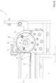
Figure 4 shows a further detail of the portion ofFigure 2 , with parts removed for clarity. -
Number 1 indicates as a whole a packaging machine for producing sealedpackages 2 of a pourable product, in particular a pourable food product, such as milk, milk drinks, yoghurt, yoghurt drinks, fruit juice, wine, tomato sauce, emulsions, beverages containing pulp, salt, sugar, etc. - In more detail,
packaging machine 1 may be configured to producepackages 2 from a web ofpackaging material 3, preferentially a web of multilayer packaging material. - More preferentially, web of
packaging material 3 may have heat seal properties (i.e. portions of the multilayer packaging material can be sealed to one another). - In further detail, web of
packaging material 3 may comprise at least one layer of fibrous material, such as e.g. paper or cardboard, and at least two layers of heat-seal plastic material, e.g. polyethylene, interposing the layer of fibrous material in between one another. Preferentially, one of these two layers of heat-seal plastic material may define the inner face ofpackages 2 contacting the pourable product. - Moreover, web of
packaging material 3 may also comprise a layer of gas- and light-barrier material, e.g. aluminum foil or ethylene vinyl alcohol (EVOH) film, preferentially being arranged between one of the layers of the heat-seal plastic material and the layer of fibrous material. - Preferentially, web of
packaging material 3 may also comprise a further layer of heat-seal plastic material being interposed between the layer of gas- and light-barrier material and the layer of fibrous material. - Preferentially, web of
packaging material 3 may comprise successively arranged patterns, each pattern defining a final graphical pattern of therespective package 2. In other words,packaging machine 1 operates, in use, such to guarantee that eachpackage 2 comprises the respective pattern. - Furthermore,
packaging machine 1 may be configured to producepackages 2 by forming atube 4 from web ofpackaging material 3, longitudinallysealing tube 4,filling tube 4 with the pourable product and to transversally seal, and preferentially transversally cuttube 4. - According to some possible non-limiting embodiments, each
package 2 may extend along a longitudinal axis. - According to some possible embodiments, each
package 2 may comprise at least a first transversal sealing band arranged at a first end ofpackage 2, and preferentially also a second transversal sealing band arranged at a second end ofpackage 2 opposite to the first end. - With particular reference to
Figure 1 ,packaging machine 1 may comprise: - a
magazine unit 10 configured to host at least one,reel 11 of web ofpackaging material 3 at ahost station 12; and - a
conveying device 13 configured to advance web ofpackaging material 3 along a web advancement path P. - According to some preferred non-limiting embodiments, conveying
device 13 may be configured to advance web ofpackaging material 3 to a tube forming station, at which, in use, web ofpackaging material 3 is formed intotube 4. Conveyingdevice 13 may also be configured to advancetube 4 along a tube advancement path Q. - According to some preferred non-limiting embodiments,
packaging machine 1 may also comprise: - a tube forming and
sealing device 15 configured to formtube 4 from the, in use, advancing web ofpackaging material 3 and to longitudinallyseal tube 4, preferentially at the tube forming station; - a
filling device 16 for fillingtube 4 with the pourable product; and - a
package forming unit 17 configured to transversally seal, and preferentially to transversally cuttube 4 for obtaining semi-finalized packs, preferentially package pouches. Preferentially,package forming unit 17 may also be configured to formtube 4. - In further detail,
packaging machine 1 may also comprise anisolation chamber 18, preferentially delimiting aninner environment 19 from anouter environment 20. Preferentially,inner environment 19 may be a sterile environment, preferably containing a controlled atmosphere. - Preferentially, tube forming and
sealing device 15 may be at least partially arranged within and configured to fold and longitudinallyseal tube 4 withinisolation chamber 18, preferentiallyinner environment 19. - Moreover,
packaging machine 1 may also comprise a sterilizing unit configured to sterilize the, in use, advancing web ofpackaging material 3, preferentially the sterilization unit being arranged upstream of tube forming and sealingdevice 15 along web advancement path P and/or downstream ofhost station 12. - In more detail, conveying
device 13 may be configured to advancetube 4 and any intermediates oftube 4 along tube advancement path Q, preferentially from tube forming and sealingdevice 15 to and/or at least partially withinpackage forming unit 17. Preferentially, with the wording intermediates oftube 4 any configuration of web ofpackaging material 3 is meant prior to obtaining the tube structure and after folding of web ofpackaging material 3 by tube forming and sealingdevice 15 has started. In other words, the intermediates oftube 4 are a result of the gradual folding of web ofpackaging material 3 so as to obtaintube 4, preferentially by overlapping the (longitudinal) edges of web ofpackaging material 3 with one another. - According to some possible non-limiting embodiments, tube forming and sealing
device 15 may be arranged such thattube 4 may have a vertical orientation. - Preferentially, filling
device 16 may comprise a filling pipe being configured to direct, in use, the pourable product intotube 4. Preferentially, the filling pipe may, in use, be at least partially placed withintube 4 for feeding, in use, the pourable product intotube 4. - According to some preferred non-limiting embodiments,
package forming unit 17 may comprise a plurality of operative devices, each one configured to manipulate, preferentially to at least partially form, to at least transversally seal and to transversally cut,tube 4 for obtainingpackages 2. - With particular reference to
Figure 1 ,magazine unit 10 may be arranged upstream ofisolation chamber 18 and/or tube forming and sealingdevice 15 and/orpackaging forming unit 17. - With particular reference to
Figures 1 to 4 ,magazine unit 10 comprises one ormore support devices 25, each one configured to rotatably carry at least onereel 11. - It is to be noted that in
Figure 1 eachreel 11, more precisely the respective web ofpackaging material 3, is illustrated as a transparent element so as to show (i.e. allow the reader to see) portions ofmagazine unit 10. Of course, in reality eachreel 11, more precisely the respective web ofpackaging material 3, is not transparent. -
Magazine unit 10 may comprise at least twosupport devices 25, arranged next to one another. More specifically,support devices 25 are arranged such to allow for arrangingreels 11 withinmagazine unit 10 in parallel and next to one another. - In more detail, each
reel 11 may comprise aspindle 26 and web ofpackaging material 3 being wound aboutspindle 26. - More specifically,
spindle 26 may extend along a center axis. - Moreover,
spindle 26 may comprise afirst end portion 27 and a second end portion (not visible) opposite tofirst end portion 27. - Additionally, each
spindle 26 may comprise a clamping group 29 (only partially shown) configured to clampreel 11 onspindle 26. - In further detail,
magazine unit 10 may comprise an inlet opening configured to allow for the introduction ofreels 11 intomagazine unit 10. Additionally, the inlet opening may allow for the removal of anexhausted reel 11 frommagazine unit 10. - More specifically, the inlet opening may have a size allowing for an operator to at least partially enter
magazine unit 10. - According to some non-limiting embodiments,
magazine unit 10 may comprise a door movable between an open position in which the door opens the inlet opening and a closed position in which the door closes the inlet opening. - With particular reference to
Figures 1 to 4 , eachsupport device 25 comprises: - at least one pair of
housing seats 30 configured to rotatably support onereel 11 at a time; and - a
pair 31 of guide rails 32. - More specifically, the
housing seats 30 of each pair may be arranged side-by-side and may be distanced from the inlet opening. Even more specifically, each pair ofhousing seats 30 may be distanced from one another along a first direction D1. - Each pair of
housing seats 30 may rotatably carry the respective spindle 26 (for rotatably carrying the respective reel 11). In particular, each spindle 26 (and therewith also the respective reel 11) may be rotatable about the respective center axis, when being placed within therespective housing seats 30. - Additionally, in use, placement of each
reel 11 into and removal of eachreel 11 frommagazine unit 11 requires the movement of eachreel 11 along a second direction D2. Moreover, second direction D2 may be transversal, more specifically (substantially) perpendicular to, first direction D1. - In further detail, one
housing seat 30 of each pair may be configured to receive the respectivefirst end portion 27 and theother housing seat 30 of the respective pair may be configured to receive the respective second end portion. - According to some non-limiting embodiments, the
respective housing seats 30 of each pair may be configured to arrange therespective spindle 26 along a horizontal direction. - Additionally, the
respective guide rails 32 of eachpair 31 may be arranged side-by-side. - Moreover, each
guide rail 32 may extend to onerespective housing seat 30. - Furthermore, each
pair 31 ofguide rails 32 may be configured to guide therespective spindle 26 to, and in particular also into, the respective pair ofhousing seats 30. - According to some non-limiting embodiments, each
guide rail 32 may extend from the respective inlet opening to therespective housing seat 30. In more detail, oneguide rail 32 of eachpair 31 may be configured to be engaged by the respectivefirst end portion 27 and theother guide rail 32 of therespective pair 31 may be configured to be engaged by the respective second end portion. - Additionally, during a loading step when a
reel 11 is loaded intomagazine unit 11, therespective spindle 26 is placed on therespective guide rails 32 and is rolled over therespective guide rails 32 towards and to therespective housing seats 30. - Each
housing seat 30 is controllable in: - an open configuration (see
Figure 3A ) in whichhousing seat 30 is configured to receive a respective end portion (first end portion 27 or second end portion) ofspindle 26; and - a closed configuration (see
Figure 3C ) in whichhousing seat 30 is fully closed and configured to lock the respective end portion (first end portion 27 or second end portion) of therespective spindle 26 within therespective housing seat 30. - By arranging the
respective housing seat 30 in the respective open configuration, it is possible to insert the respective end portions ofspindle 26 into therespective housing seats 30 and by arranging therespective housing seat 30 in the respective closed configuration, it is possible to guarantee a correct and safe rotation ofreels 11. - Additionally and with reference to
Figure 3B , eachhousing seat 30 is controllable in a respective intermediate configuration (distinct from the open configuration and the closed configuration) in which the housing seat is only partially closed, and in particular configured to impede the respective end portion (first end portion 27 or second end portion) of therespective spindle 26 to return onto therespective guide rail 32. - It should be noted that an operator, once a
new reel 11 has been coupled to the respective support device 25 (i.e. therespective spindle 26 has been placed within the respective housing seats 30), needs to execute further operations on thereel 11, so as to prepare thereel 11 for its further use withinpackaging machine 1. Thereby, the operator needs to rotate thereel 11 and therewith also thespindle 26. By having the further possibility of controllinghousing seats 30 in the intermediate configurations, it is possible to movehousing seats 30 from the open configuration to the intermediate configuration while the operator is present withinmagazine unit 10 without the risk of hurting the operator as thehousing seats 30 are not controlled into the closed position while the operator is withinmagazine unit 10. - In further detail,
packaging machine 1 and/ormagazine unit 10 may comprise a control unit configured to at least controlhousing seats 30 between the respective opening configurations, intermediate configurations and closed configurations. - More specifically, the control unit may be configured to move the
housing seats 30 at first from the respective open configuration to the respective intermediate configuration and then from the respective intermediate configuration to the respective closed configuration. - Additionally, the control unit may be configured to control
housing seats 30 directly from the closed configuration to the open configuration or, alternatively, from the closed configuration to the intermediate configuration and then to the open configuration. - According to some possible embodiments, the control unit may be configured to simultaneously move the
respective housing seats 30 of the respective pair from the respective open configurations to the respective intermediate configurations and from the respective intermediate configurations to the respective closed configurations. - According to some advantageous embodiments, the control unit may be configured to control
housing seats 30 from the respective intermediate configurations to the respective closed configurations only in the case that the door ofmagazine unit 10 is in the closed position. - With particular reference to
Figures 1 and2 ,magazine unit 10 may further comprise one ormore actuation devices 33, such as a linear motor, configured to controlhousing seats 30 between the respective open configurations, the respective intermediate configurations and the respective closed configurations. - More specifically,
magazine unit 10 comprises onerespective actuation device 33 for eachhousing seat 30 and eachactuation device 33 may be coupled to therespective housing seat 30. - Advantageously, the control unit may be operatively connected to each
actuation device 33 and may be configured to selectively controlactuation devices 33 so as to controlhousing seats 30. - In more detail, each
housing seat 30 may be rotatable around a respective rotation axis C. - Additionally, each
housing seat 30 may be arranged in a first angular position (seeFigure 3A ), a second angular position (seeFigure 3B ) and a third angular position (seeFigure 3C ) with respect to the respective rotation axis C when being controlled in, respectively, the respective open configuration, the respective intermediate configuration and the respective closed configuration. - More specifically, each second angular position is different from the respective first angular position and each third angular position is different from the respective first angular position and the respective second angular position.
- In even more detail, each
actuation device 33 may be configured to rotate the respective housing seat(s) 30 in an angular direction from the respective first angular position to the respective second angular position and from the respective second angular position to the respective third angular position. Each second angular position is interposed between the respective first angular position and the respective third angular position with respect to the angular direction. - In further detail and with particular reference to
Figures 1 to 3C , eachguide rail 32 may have aguide surface 34 configured to supportspindle 26, more specifically one of the respectivefirst end portion 27 and the respective second end portion. - Each
guide surface 34 extend from a firstterminal portion 35 to a secondterminal portion 36. - In more detail, each
second terminal portion 36 may be adjacent to onerespective housing seat 30. - According to some possible embodiments, each
first terminal portion 35 may be positioned adjacently to the inlet opening. - Moreover, each
housing seat 30 may comprise ahousing channel 40. - In more detail, each
housing seat 30, in particular therespective housing channel 40, may comprise aninlet aperture 41 configured to allow for introducing the respective end portion ofspindle 26 into and discharging the respective end portion ofspindle 26 from therespective housing seat 30, in particular therespective housing channel 40. - In further detail,
housing channel 40 is angularly movable about the respective rotation axis C. More specifically,housing channel 40 can be selectively positioned in the respective first angular position, the respective second angular position and the respective third angular position by operation ofactuation device 33. - Moreover, each
housing channel 40 may comprise anengagement surface 42 configured to guide therespective spindle 26, in particular the respectivefirst end portion 27 or the respective second end portion intohousing channel 40 and out ofhousing channel 40. - According to some non-limiting embodiments, each
inlet aperture 41 and/or eachengagement surface 42 and the respective secondterminal portion 36 may be aligned with respect to one another with therespective housing seat 30 being in the open configuration (seeFigure 3A ) and may be unaligned with respect to one another with therespective housing seat 30 being in the respective intermediate configuration (seeFigure 3B ) and in the respective closed configuration (seeFigure 3C ). - In particular, when
inlet aperture 41 and/orengagement surface 42 and the respective secondterminal portion 36 are aligned with respect to one another the respective end portion ofspindle 26 may be introduced into and removed from therespective housing seat 30. Wheninlet aperture 41 and/orengagement surface 42 and the respective secondterminal portion 36 are unaligned with respect to one another the respective end portion ofspindle 26 is retained within therespective housing seat 30. - More specifically, each
engagement surface 42 may be flush with therespective guide surface 34 with therespective housing seat 30 being in the open configuration (seeFigure 3A ). - Additionally, each
housing seat 30 and therespective guide rail 32 may be separated from one another by means of arespective edge 43 originating from positioning ofhousing seat 30 in the respective intermediate configuration (seeFigure 3B ). In the example shown, eachedge 43 may be substantially defined by controlling therespective housing seat 30 in the respective intermediate configuration. - With particular reference to
Figures 2 to 4 , eachhousing channel 40 may comprise anabutment surface 44 opposite to therespective inlet aperture 41 and the respective end portion (first end portion 27 or second end portion) of therespective spindle 26 abuts against theabutment surface 44 when being arranged inhousing seat 30. - According to some non-limiting embodiments,
magazine unit 10 may also comprise a pair ofsupport structures 45, eachsupport structure 45 being configured to carry, in particular to rotatably carry, onerespective housing seat 30. - More specifically, each
support structure 45 may comprise a housing space and therespective housing seat 30 being rotatably movable within the respective housing space. - Additionally, each
support structure 45 may comprise a plurality of bearing elements 47 (e.g. ball elements or roller elements or the like) arranged within the respective housing space and carrying therespective housing seat 30. - According to some possible non-limiting embodiments, each
support structure 45 may also comprise awall 48, in particular at least partially delimiting the respective housing space. - Advantageously, each
wall 48 may be arranged and/or designed such to close therespective inlet aperture 41 with therespective housing seat 30 being in the respective closed configuration. Thus,wall 48 guarantees that the respective end portion ofspindle 26 cannot exit through therespective inlet aperture 41. - Additionally, each
wall 48 may be arranged and/or designed such to partially close therespective inlet aperture 41 with therespective housing seat 30 being in the respective intermediate configuration. - According to some possible non-limiting embodiments, the control unit may be configured to control each
housing seat 30 after having received the respective end portion (eitherfirst end portion 27 or second end portion) of therespective spindle 26 from the open configuration to the intermediate configuration and afterwards from the intermediate configuration to the closed configuration. - Additionally, the control unit may be configured to control each
housing seat 30 from the respective intermediate configuration to the closed configuration only with the door ofmagazine unit 10 being closed. - In use,
packaging machine 1forms packages 2 filled with the pourable product. - In more detail, conveying
device 13 advances web ofpackaging material 3 frommagazine unit 10, preferentially tohost station 12. - In further detail, conveying device advances web of
packaging material 3 from host station 7 to formingstation 10 at which web ofpackaging material 3 is formed intotube 4. - Conveying
device 13further advances tube 4 along tube advancement path Q to package formingunit 17. During advancement oftube 4, fillingdevice 16 fillstube 4 with the pourable product. - Preferentially, during advancement of web of
packaging material 3 along web advancement path P web ofpackaging material 3 is sterilized at the sterilization station. -
Package forming unit 13 forms andtransversally seals tube 4 and, preferentially, alsotransversally cuts tube 4 so as to obtainpackages 2. - Additionally, during operation, each
reel 11 gets exhausted. In order to avoid interruption of production, a new web ofpackaging material 3 is spliced to web ofpackaging material 3 in use. - Additionally, repeatedly one feeds
new reels 11 intomagazine unit 10. - Therefore, one needs to repeatedly couple and uncouple
reels 11 to and fromsupport device 25. - A method for loading
spindle 26 carrying wound-up web ofpackaging material 3 intomagazine unit 10 comprises the steps of: - a.) providing
housing seats 30 being in the open configurations; - b.) placing
spindle 26 on onepair 31 ofguide rails 32; - c.) guiding
spindle 26 alongguide rails 32, more specifically the respective guide surfaces 34, and into therespective housing seats 30, more specifically into therespective housing channels 40; - d.) moving
housing seats 30 from the open configurations to the intermediate configurations; and - e.) moving the housing seats from the intermediate configurations to the closed configurations.
- In more detail, during step a.), the control unit commands actuation device(s) 33 so as to set the
respective housing seats 30 in the respective first angular positions. - Moreover, during the steps d.) and e.)
housing seats 30 rotate about respective rotation axes C. - More specifically, during the step d.) the control unit commands actuation device(s) 33 so as to set the
respective housing seats 30 in the respective second angular positions. - More specifically, during the step e.) the control unit commands actuation device(s) 33 so as to set the
respective housing seats 30 in the respective third angular positions. - Advantageously, the step e.) may only be executed in the case that the door of
magazine unit 10 is in a closed position. - The advantages of
magazine unit 10 according to the present invention will be clear from the foregoing description. - In particular, the loading of
spindles 26 intomagazine unit 10 is facilitated by additionally mitigating the risk of injuries. - More specifically, a technical operator does not need to leave
magazine unit 10 whilehousing seats 30 move from the respective open configurations to the respective intermediate configurations as positioninghousing seats 30 in the intermediate configuration is safe. Afterwards, the technical operator can preparespindle 26 and the respective web ofpackaging material 3, e.g. for a splicing process. Once, the technical operator has terminated the preparation activities, the technical operator can leavemagazine unit 10 and then thehousing seats 30 are controlled in the respective closed configurations. - Clearly, changes may be made to
packaging machine 1, and/ormagazine unit 10 and/or the method as described herein without, however, departing from the scope of protection as defined in the accompanying claims.
Claims (15)
- - Magazine unit (10) for a packaging machine (1) comprising:- an inlet opening configured to allow for the introduction of a reel (11) having a spindle (26) carrying a wound-up web of packaging material (3) into the magazine unit (10);- at least one pair of housing seats (30) configured to rotatably support the spindle (26) carrying the wound-up web of packaging material (3), the respective housing seats (30) of the at least one pair of housing seats (30) being arranged side-by-side and distanced from the inlet opening;
wherein each housing seat (30) is controllable in:- an open configuration in which the housing seat (30) is configured to receive a respective end portion (27) of the spindle (26);- a closed configuration in which the housing seat (30) is fully closed and configured to lock the respective end portion (27) of the spindle (26) within the housing seat (30); and- an intermediate configuration in which the housing seat (30) is only partially closed. - - Magazine unit according to claim 1, and further comprising a pair (31) of guide rails (32), the guide rails (32) being arranged side-by-side and each guide rail (32) extending to one respective housing seat (30); wherein the guide rails (32) are configured to guide the spindle (26) to the pair of housing seats (30);
wherein each housing seat (30) is configured such that when being controlled in the respective intermediate configuration, the housing seat (30) is partially closed for impeding the respective end portion (27) of the spindle (26) to return onto the respective guide rail (32). - - Magazine unit according to claim 1 or 2, and further comprising one or more actuation devices (33) configured to control the housing seats (30) between the open configuration, the intermediate configuration and the closed configuration.
- - Magazine unit according to any one of the preceding claims, wherein each housing seat (30) is rotatable around a respective rotation axis (C);wherein each housing seat (30) is arranged in a first angular position, a second angular position and a third angular position with respect to the respective rotation axis (C) when being controlled in, respectively, the respective open configuration, the respective intermediate configuration and the respective closed configuration;wherein the second angular position is different from the first angular position and the third angular position is different from the first angular position and the second angular position.
- - Magazine unit according to claim 4, wherein the actuation device is configured to rotate each housing seat (30) in an angular direction from the first angular position to the second angular position and from the second angular position to the third angular position;
wherein the second angular position is interposed between the first angular position and the third angular position with respect to the angular direction. - - Magazine unit according to any one of the preceding claims, wherein each housing seat (30) comprises a housing channel (40) having an inlet aperture (41);wherein each guide rail (32) comprises a guide surface (34) having a terminal portion (36);wherein each inlet aperture (41) and the respective terminal portion (36) are aligned with respect to one another with the housing seat (30) being in the open configuration and are unaligned with respect to one another with the respective housing seat (30) being in the respective intermediate configuration and in the respective closed configuration.
- - Magazine unit according to any one of the preceding claims, and further comprising a pair of support structures (45), each support structure (45) being configured to carry one respective housing seat (30);wherein each housing seat (30) comprises a housing channel (40) having an inlet aperture (41);wherein each support structure (45) comprises a wall (48) arranged and/or designed such to close the respective inlet aperture (41) with the respective housing seat (30) being in the respective closed configuration.
- - Magazine unit according to claim 7, wherein each wall (48) is arranged and/or designed such to partially close the respective inlet aperture (41) with the respective housing seat (30) being in the respective intermediate configuration.
- - Magazine unit according to any one of claims 6 to 8, wherein each housing channel (40) comprises an abutment surface (44) opposite to the respective inlet aperture (41) and the respective end portion (27) of the respective spindle (26) abuts against the abutment surface (44) when being arranged in the housing seat (30).
- - Magazine unit according to any one of the preceding claims, and further comprising a control unit configured to control each housing seat (30) after having received the respective end portion (27) of the respective spindle (26) from the open configuration to the intermediate configuration and afterwards from the intermediate configuration to the closed configuration.
- - Magazine unit according to claim 10, wherein the magazine unit comprises a door movable between an open position and a closed position;
wherein the housing seats (30) is controllable from the intermediate configurations to the closed configurations by the control only when the door is in the closed position. - - A packaging machine (1) for producing sealed packages (2) of a pourable product comprising:- an isolation chamber (18) separating an inner environment (19) from an outer environment (20);- a tube forming and sealing device (15) at least partially arranged within the isolation chamber (18) and configured to form and longitudinally seal a tube (4) from a web of packaging material (3) at a tube forming station;- a filling device (16) for filling the tube (3) with the pourable product;- a package forming unit (17) configured to manipulate the tube (3) for forming the packages (2);- a conveying device (13) for advancing the web of packaging material (3) along a web advancement path (P) from a host station (12) to the tube forming station and for advancing the tube (3) along a tube advancement path (Q) to the package forming unit (13); and
a magazine unit (10) according to any one of the preceding claims. - - Method for loading a spindle (26) carrying a wound-up web of packaging material (3) into a magazine unit (10) according to any one of claims 1 to 10;
the method comprises the steps of:a.) providing the housing seats (30) being in the open configurations;b.) placing the spindle (26) on one pair (31) of guide rails (32);c.) guiding the spindle (26) along the guide rails (32) and into the respective housing seats (30);d.) moving the housing seats (30) from the open configurations to the intermediate configurations; ande.) moving the housing seats (30) from the intermediate configurations to the closed configurations. - - Method according to claim 13, wherein during the steps d.) and e.) the housing seats (30) rotate about respective rotation axes (C).
- - Method according to claim 13 or 14, wherein the step e.) is only executed in the case that a door of the magazine unit (10) is in a closed position.
Applications Claiming Priority (1)
| Application Number | Priority Date | Filing Date | Title |
|---|---|---|---|
| IT102023000019536A IT202300019536A1 (en) | 2023-09-22 | 2023-09-22 | STORAGE UNIT FOR A PACKAGING MACHINE, PACKAGING MACHINE HAVING A STORAGE UNIT AND METHOD FOR LOADING A STORAGE UNIT |
Publications (1)
| Publication Number | Publication Date |
|---|---|
| EP4527769A1 true EP4527769A1 (en) | 2025-03-26 |
Family
ID=88965056
Family Applications (1)
| Application Number | Title | Priority Date | Filing Date |
|---|---|---|---|
| EP24200472.9A Pending EP4527769A1 (en) | 2023-09-22 | 2024-09-16 | Magazine unit for a packaging machine, packaging machine having a magazine unit and method for loading a magazine unit |
Country Status (4)
| Country | Link |
|---|---|
| EP (1) | EP4527769A1 (en) |
| CN (1) | CN121889325A (en) |
| IT (1) | IT202300019536A1 (en) |
| WO (1) | WO2025061597A1 (en) |
Citations (3)
| Publication number | Priority date | Publication date | Assignee | Title |
|---|---|---|---|---|
| US4392912A (en) * | 1980-04-15 | 1983-07-12 | Molins Limited | Bobbin changer for joining successive reels of web of the cigarette industry |
| US5186408A (en) * | 1990-05-14 | 1993-02-16 | Mirek Planeta | Machine for winding elongated strips on an axle mounted core |
| EP3517467A1 (en) * | 2018-01-29 | 2019-07-31 | Tetra Laval Holdings & Finance S.A. | Magazine unit for a packaging machine, packaging machine having a magazine unit and method for loading a magazine unit |
-
2023
- 2023-09-22 IT IT102023000019536A patent/IT202300019536A1/en unknown
-
2024
- 2024-09-16 WO PCT/EP2024/075732 patent/WO2025061597A1/en active Pending
- 2024-09-16 EP EP24200472.9A patent/EP4527769A1/en active Pending
- 2024-09-16 CN CN202480060035.6A patent/CN121889325A/en active Pending
Patent Citations (3)
| Publication number | Priority date | Publication date | Assignee | Title |
|---|---|---|---|---|
| US4392912A (en) * | 1980-04-15 | 1983-07-12 | Molins Limited | Bobbin changer for joining successive reels of web of the cigarette industry |
| US5186408A (en) * | 1990-05-14 | 1993-02-16 | Mirek Planeta | Machine for winding elongated strips on an axle mounted core |
| EP3517467A1 (en) * | 2018-01-29 | 2019-07-31 | Tetra Laval Holdings & Finance S.A. | Magazine unit for a packaging machine, packaging machine having a magazine unit and method for loading a magazine unit |
Also Published As
| Publication number | Publication date |
|---|---|
| WO2025061597A1 (en) | 2025-03-27 |
| IT202300019536A1 (en) | 2025-03-22 |
| CN121889325A (en) | 2026-04-17 |
Similar Documents
| Publication | Publication Date | Title |
|---|---|---|
| EP2258643B1 (en) | Method for feeding a supply station of a packaging unit with a new reel of sheet packaging material, sheet packaging material holder and lift truck | |
| EP4032819B1 (en) | Infeed conveyor for a folding apparatus, folding apparatus having an infeed conveyor and packaging machine having a folding apparatus | |
| EP4357253A1 (en) | Folding apparatus and packaging machine having a folding apparatus | |
| US20220177173A1 (en) | Packaging machine for producing sealed packages | |
| EP4223681A1 (en) | Apparatus for applying a sealing strip onto a web of packaging material, reel and method | |
| EP4265533A1 (en) | Infeed conveyor for a folding apparatus, folding apparatus having an infeed conveyor and packaging machine having a folding apparatus | |
| WO2025061597A1 (en) | Magazine unit for a packaging machine, packaging machine having a magazine unit and method for loading a magazine unit | |
| JP7374110B2 (en) | Web alignment device, packaging machine with web alignment device, and splicing method | |
| CN111655600B (en) | Cartridge unit for a packaging machine, packaging machine with a cartridge unit and method for loading a cartridge unit | |
| EP4506288A1 (en) | Support device for a reel, packaging machine having a support device for a reel, method for coupling a reel to a support device and method for uncoupling a reel from a support device | |
| EP4647380A1 (en) | Magazine apparatus for a packaging machine and packaging machine having a magazine apparatus | |
| EP4647378A1 (en) | Magazine apparatus for a packaging machine and packaging machine having a magazine apparatus | |
| EP4647379A1 (en) | Magazine apparatus for a packaging machine, packaging machine having a magazine apparatus and a packaging plant | |
| EP4414300A1 (en) | Magazine unit for a packaging machine, packaging machine having a magazine unit and method for operating a magazine unit for a packaging machine | |
| EP4549329A1 (en) | Package forming apparatus for a packaging machine and packaging machine for forming packages filled with a pourable product | |
| EP4474299A1 (en) | Package forming apparatus and packaging machine for forming packages | |
| EP4606749A1 (en) | Splicing unit for splicing a sealing strip of heat-sealable material, apparatus for applying a sealing strip to a web of packaging material and packaging machine for forming sealed packages | |
| EP4458689A1 (en) | Package forming apparatus for a packaging machine, packaging machine for forming packages filled with a pourable product and method for forming packages | |
| EP4357254A1 (en) | Folding apparatus and packaging machine having a folding apparatus | |
| EP4588646A1 (en) | Apparatus for applying a sealing strip of a heat-sealable material to a web of packaging material and packaging machine for forming sealed packages | |
| EP4656534A1 (en) | Infeed conveyor for a folding apparatus, folding apparatus having an infeed conveyor and packaging machine having a folding apparatus for forming finalized packages from semi-finalized packs | |
| EP4357260A1 (en) | Infeed conveyor for a folding apparatus, folding apparatus having an infeed conveyor and packaging machine having a folding apparatus | |
| CN120693284A (en) | Capping device for packaging machine and packaging machine having the same |
Legal Events
| Date | Code | Title | Description |
|---|---|---|---|
| PUAI | Public reference made under article 153(3) epc to a published international application that has entered the european phase |
Free format text: ORIGINAL CODE: 0009012 |
|
| STAA | Information on the status of an ep patent application or granted ep patent |
Free format text: STATUS: THE APPLICATION HAS BEEN PUBLISHED |
|
| AK | Designated contracting states |
Kind code of ref document: A1 Designated state(s): AL AT BE BG CH CY CZ DE DK EE ES FI FR GB GR HR HU IE IS IT LI LT LU LV MC ME MK MT NL NO PL PT RO RS SE SI SK SM TR |
|
| STAA | Information on the status of an ep patent application or granted ep patent |
Free format text: STATUS: REQUEST FOR EXAMINATION WAS MADE |
|
| 17P | Request for examination filed |
Effective date: 20250926 |