EP4527768A1 - Medium feeding device and image forming apparatus - Google Patents
Medium feeding device and image forming apparatus Download PDFInfo
- Publication number
- EP4527768A1 EP4527768A1 EP24159542.0A EP24159542A EP4527768A1 EP 4527768 A1 EP4527768 A1 EP 4527768A1 EP 24159542 A EP24159542 A EP 24159542A EP 4527768 A1 EP4527768 A1 EP 4527768A1
- Authority
- EP
- European Patent Office
- Prior art keywords
- unit
- recording media
- image
- feeding device
- image capturing
- Prior art date
- Legal status (The legal status is an assumption and is not a legal conclusion. Google has not performed a legal analysis and makes no representation as to the accuracy of the status listed.)
- Pending
Links
Images






Classifications
-
- B—PERFORMING OPERATIONS; TRANSPORTING
- B65—CONVEYING; PACKING; STORING; HANDLING THIN OR FILAMENTARY MATERIAL
- B65H—HANDLING THIN OR FILAMENTARY MATERIAL, e.g. SHEETS, WEBS, CABLES
- B65H3/00—Separating articles from piles
- B65H3/46—Supplementary devices or measures to assist separation or prevent double feed
- B65H3/48—Air blast acting on edges of, or under, articles
-
- B—PERFORMING OPERATIONS; TRANSPORTING
- B65—CONVEYING; PACKING; STORING; HANDLING THIN OR FILAMENTARY MATERIAL
- B65H—HANDLING THIN OR FILAMENTARY MATERIAL, e.g. SHEETS, WEBS, CABLES
- B65H7/00—Controlling article feeding, separating, pile-advancing, or associated apparatus, to take account of incorrect feeding, absence of articles, or presence of faulty articles
- B65H7/02—Controlling article feeding, separating, pile-advancing, or associated apparatus, to take account of incorrect feeding, absence of articles, or presence of faulty articles by feelers or detectors
- B65H7/14—Controlling article feeding, separating, pile-advancing, or associated apparatus, to take account of incorrect feeding, absence of articles, or presence of faulty articles by feelers or detectors by photoelectric feelers or detectors
-
- B—PERFORMING OPERATIONS; TRANSPORTING
- B65—CONVEYING; PACKING; STORING; HANDLING THIN OR FILAMENTARY MATERIAL
- B65H—HANDLING THIN OR FILAMENTARY MATERIAL, e.g. SHEETS, WEBS, CABLES
- B65H2553/00—Sensing or detecting means
- B65H2553/40—Sensing or detecting means using optical, e.g. photographic, elements
- B65H2553/42—Cameras
-
- B—PERFORMING OPERATIONS; TRANSPORTING
- B65—CONVEYING; PACKING; STORING; HANDLING THIN OR FILAMENTARY MATERIAL
- B65H—HANDLING THIN OR FILAMENTARY MATERIAL, e.g. SHEETS, WEBS, CABLES
- B65H2553/00—Sensing or detecting means
- B65H2553/60—Details of intermediate means between the sensing means and the element to be sensed
-
- B—PERFORMING OPERATIONS; TRANSPORTING
- B65—CONVEYING; PACKING; STORING; HANDLING THIN OR FILAMENTARY MATERIAL
- B65H—HANDLING THIN OR FILAMENTARY MATERIAL, e.g. SHEETS, WEBS, CABLES
- B65H2801/00—Application field
- B65H2801/03—Image reproduction devices
-
- B—PERFORMING OPERATIONS; TRANSPORTING
- B65—CONVEYING; PACKING; STORING; HANDLING THIN OR FILAMENTARY MATERIAL
- B65H—HANDLING THIN OR FILAMENTARY MATERIAL, e.g. SHEETS, WEBS, CABLES
- B65H2801/00—Application field
- B65H2801/03—Image reproduction devices
- B65H2801/06—Office-type machines, e.g. photocopiers
-
- B—PERFORMING OPERATIONS; TRANSPORTING
- B65—CONVEYING; PACKING; STORING; HANDLING THIN OR FILAMENTARY MATERIAL
- B65H—HANDLING THIN OR FILAMENTARY MATERIAL, e.g. SHEETS, WEBS, CABLES
- B65H2801/00—Application field
- B65H2801/39—Scanning
Definitions
- the present disclosure relates to medium feeding devices and image forming apparatuses.
- Japanese Unexamined Patent Application Publication No. 2020-152535 discloses a sheet feeding device including an air blower that blows air to a sheet bundle loaded on a sheet loading section so as to cause upper sheets of the sheet bundle to levitate, a feeder that feeds an uppermost one of the levitated sheets, and an imager that captures an image of the sheet levitated by the air blower.
- the imaging range of the imager is set such that an image of a feed surface of the feeder and an image of at least the uppermost sheet of the sheet bundle loaded on the sheet loading section are captured.
- a conceivable medium feeding device includes a supplier that causes multiple loaded recording media to levitate and be separated from each other by supplying air to the recording media from an edge of the recording media, a feeding unit that feeds an uppermost one of the recording media separated by the supplier in a feeding direction, and an image capturing unit that captures an image of a lateral edge of the multiple recording media.
- the image capturing unit is to directly capture the image of the lateral edge of the multiple recording media, the image capturing unit is be disposed at a position facing the lateral edge of the multiple recording media. Therefore, the degree of freedom with respect to the installation position of the image capturing unit is low.
- a medium feeding device comprising: a supplier that causes a plurality of loaded recording media to levitate and be separated from each other by supplying air to the recording media from an edge of the recording media; a feeding unit that feeds, in a feeding direction, an uppermost one of the recording media separated by the supplier; a contact section that comes into contact with a lateral edge of the plurality of recording media from a lateral side of the plurality of recording media; a projection unit that is provided at the contact section and onto which an image of the lateral edge of the plurality of recording media is projected in the feeding direction; and an image capturing unit that is disposed in the feeding direction relative to the plurality of recording media and that captures the image projected on the projection unit in a state where the plurality of recording media are supplied with the air from the supplier.
- the image capturing unit may be disposed at a position where the image capturing unit does not interfere with each recording medium fed by the feeding unit.
- the image capturing unit may be disposed toward the lateral side relative to a position where each recording medium fed by the feeding unit passes.
- the contact section may be movable toward the lateral side of the recording media, and the image capturing unit may move toward the lateral side in conjunction with movement of the contact section.
- the projection unit may be attachable to and detachable from the contact section.
- the medium feeding device may further comprise a light source that radiates light onto the lateral edge of the plurality of loaded recording media and does not radiate the light onto a projection surface of the projection unit onto which the image is projected.
- an image forming apparatus comprising the medium feeding device according to any one of the first to seventh aspects and an image forming unit that forms an image onto each recording medium fed from the medium feeding device.
- the degree of freedom with respect to the installation position of the image capturing unit may be enhanced, as compared with a case where the image capturing unit directly captures the image of the lateral edge of the plurality of recording media.
- a feeding failure of each recording medium may be suppressed, as compared with a case where the image capturing unit is disposed at a position where it interferes with each recording medium fed by the feeding unit.
- the degree of freedom with respect to the installation position of the image capturing unit in the up-down direction may be enhanced, as compared with a case where the image capturing unit is disposed above or below the position where each recording medium fed by the feeding unit passes.
- an out-of-focus state of the image capturing unit when the image capturing unit captures the image of the lateral edge of the plurality of recording media projected on the projection unit may be suppressed, as compared with a case where the image capturing unit is always set at a fixed position.
- an out-of-focus state of the image capturing unit when the image capturing unit captures the image of the lateral edge of the plurality of recording media projected on the projection unit may be suppressed, as compared with a case where the image capturing unit is separated from the contact section and moves independently therefrom.
- the projection unit may be cleaned readily, as compared with a case where the projection unit is fixed to the contact section in a non-detachable manner.
- an image capturing failure occurring when the image capturing unit captures the image of the lateral edge of the plurality of recording media projected on the projection unit may be suppressed, as compared with a case where the light source also radiates the light onto the projection surface of the projection unit.
- An arrow H denoted in each drawing indicates an up-down direction (vertical direction) of an apparatus
- an arrow W indicates a width direction (horizontal direction) of the apparatus
- an arrow D indicates a depth direction (horizontal direction) of the apparatus.
- An image forming apparatus 100 forms an image onto a sheet member P, and includes a medium feeding device 10 and an image forming unit 102, as illustrated in Fig. 1 .
- the medium feeding device 10 may be provided in advance in an apparatus body 101 of the image forming apparatus 100, or may be optionally added and attached to the apparatus body 101 of the image forming apparatus 100.
- the sheet member P is an example of a recording medium.
- the image forming unit 102 illustrated in Fig. 1 is a component that forms an image onto the sheet member P fed from the medium feeding device 10.
- the image forming unit 102 used is of an electrophotographic type that forms an image onto the sheet member P by using toner.
- An electrophotographic image forming unit forms an image onto the sheet member P by performing, for example, charging, exposure, developing, transfer, and fixing steps.
- an electrophotographic image forming unit forms an image onto a transfer body by performing charging, exposure, developing, and transfer steps, transfers the image from the transfer body to the sheet member P, and subsequently fixes the image onto the sheet member P, thereby forming the image on the sheet member P.
- the example of the image forming unit is not limited to the electrophotographic image forming unit mentioned above, and may be any of various image forming units, such as an inkjet image forming unit.
- an inkjet image forming unit forms an image onto the sheet member P by ejecting ink droplets from an ejector onto the sheet member P.
- the medium feeding device 10 illustrated in Fig. 1 feeds the sheet member P toward the image forming unit 102.
- the medium feeding device 10 includes a loading section 12 and a feeding unit 16.
- the medium feeding device 10 includes a side guide 13 and a supplier 14.
- the medium feeding device 10 includes a leading edge guide 15, a projection unit 20, a camera 18, and a light source 22.
- the medium feeding device 10 includes a controller 40.
- the side guide 13 is an example of a contact section.
- the camera 18 is an example of an image capturing unit.
- the loading section 12 is a component on which the sheet member P is loaded. As illustrated in Fig. 2 , the loading section 12 includes a bottom plate 12A on which multiple sheet members P are loaded in a stacked state in the up-down direction, and also includes an ascending-descending device (not illustrated) that causes the bottom plate 12A to ascend and descend in the up-down direction. The ascending-descending device causes the bottom plate 12A to ascend such that the position of an uppermost sheet member P of the sheet members P loaded on the bottom plate 12A is set at a predetermined height.
- the side guide 13 is a component that comes into contact with a lateral edge of the multiple sheet members P from a lateral side of the multiple sheet members P.
- the side guide 13 is disposed at each of opposite lateral edges of the sheet members P loaded on the bottom plate 12A.
- the side guide 13 is provided as a pair.
- the pair of side guides 13 come into contact with the opposite lateral edges (i.e., opposite edges of the sheet members P in the width direction (the direction of the arrow Y)) of the sheet members P loaded on the bottom plate 12A, so as to limit the position of the sheet members P in the width direction.
- the pair of side guides 13 are movable toward the lateral sides of the sheet members P.
- the pair of side guides 13 are attached to a device body 11 (see Fig. 1 ) of the medium feeding device 10 in a slidable manner in the depth direction serving as the width direction (see the direction of the arrow Y) of the sheet members P.
- a user manually moves the side guides 13 in the width direction of the sheet members P in conformity with the widthwise size of the sheet members P, so that the side guides 13 come into contact with the opposite lateral edges of the sheet members P, thereby limiting the position of the sheet members P in the width direction.
- the leading edge guide 15 is a component that comes into contact with the leading edge of the multiple sheet members P from the downstream side (i.e., in the direction of an arrow W1 in Fig. 2 ) in a feeding direction, to be described later, relative to the multiple sheet members P.
- the leading edge guide 15 is disposed at the leading edge of the sheet members P loaded on the bottom plate 12A.
- the leading edge guide 15 comes into contact with the leading edge (i.e., downstream edge in the feeding direction to be described later) of the sheet members P loaded on the bottom plate 12A, so as to limit the position of the sheet members P in the feeding direction (i.e., transport direction).
- the supplier 14 is a component that supplies air toward an edge of the multiple sheet members P loaded on the loading section 12 to cause the sheet members P to levitate, thereby separating the sheet members P from one another.
- the supplier 14 is disposed inside one of the pair of side guides 13 (i.e., the front one in the depth direction D in Fig. 2 ).
- the supplier 14 includes a duct 50 having a supply port 50A and a blower 54 that supplies air into the duct 50.
- the duct 50 extends in the up-down direction.
- An area located at the upper end of the duct 50 and facing the loaded sheet members P is provided with the supply port 50A.
- the blower 54 is disposed below the duct 50 and supplies air into the duct 50.
- the air supplied into the duct 50 by the blower 54 travels upward through the duct 50 and is supplied toward a lateral edge (i.e., an example of an edge) of the sheet members P via the supply port 50A. Then, the air is supplied between upper sheet members P of the multiple loaded sheet members P, so that multiple sheet members P levitate and become separated from one another.
- the supplier 14 supplies the air toward one lateral edge (i.e., the front one in the depth direction D in Fig. 2 ) of the multiple sheet members P.
- the exemplary embodiment is not limited to this configuration.
- the supplier 14 may supply the air toward at least one of the other lateral edge (i.e., the rear one in the depth direction D in Fig. 2 ), the leading edge (i.e., the downstream edge in the feeding direction to be described later), and the trailing edge (i.e., the upstream edge in the feeding direction to be described later).
- the feeding unit 16 is a component that feeds, in the feeding direction (see the arrow W1 in Fig. 2 ), an uppermost one of the sheet members P separated by the supplier 14. In detail, as illustrated in Fig. 2 , the feeding unit 16 is disposed above the uppermost sheet member P of the multiple sheet members P loaded on the bottom plate 12A of the loading section 12.
- the feeding unit 16 includes a suction unit 30 and a feed roller 26.
- the suction unit 30 is disposed above a leading-edge area of the uppermost sheet member P in the loaded state.
- the suction unit 30 suctions the uppermost levitated sheet member P and moves the sheet member P in the suctioned state in the feeding direction (see the arrow W1 in Fig. 2 ), thereby transporting the sheet member P in the feeding direction.
- the feed roller 26 is disposed in the feeding direction relative to the suction unit 30, receives the sheet member P transported by the suction unit 30, and feeds the received sheet member P toward the image forming unit 102 (see Fig. 1 ).
- the projection unit 20 is a component that is provided at the side guide 13 and onto which an image of the lateral edge of the multiple sheet members P is projected in the feeding direction.
- the projection unit 20 is constituted of a reflecting mirror serving as a reflector that reflects light from the lateral edge of the sheet members P in the feeding direction.
- the projection unit 20 receives the light from the lateral edge of the sheet members P and reflects the light in the feeding direction. Accordingly, the image of the lateral edge of the multiple sheet members P is projected onto the projection unit 20 in the feeding direction.
- the projection unit 20 is attached to the side guide 13 such that a projection surface 20A onto which the image is projected is set at a 45-degree angle relative to the feeding direction and the width direction of the sheet members P. Furthermore, the projection unit 20 is attachable to and detachable from the side guide 13. The projection unit 20 is attached to the side guide 13 in a detachable manner from the side guide 13. Accordingly, maintenance and inspection processes, including a cleaning process of the projection surface 20A, may be executed on the projection unit 20 in a state where the side guide 13 is attached to the device body 11 of the medium feeding device 10.
- the side guide 13 is open in two directions relative to the projection unit 20, namely, toward the downstream side in the feeding direction and toward the lateral edge of the sheet members P, and is closed in directions (i.e., other directions including the up-down direction) other than the two directions relative to the projection unit 20. Therefore, light is inputtable to and outputtable from the projection unit 20 in the two directions, namely, toward the downstream side in the feeding direction and toward the lateral edge of the sheet members P.
- the light source 22 is a component that radiates light onto the lateral edge of the multiple sheet members P loaded on the loading section 12.
- the light source 22 is disposed alongside the lateral edge of the sheet members P, as well as downstream of the side guide 13 in the feeding direction and above the leading edge guide 15 (see Figs. 6 and 7 ).
- the light source 22 radiates light onto the lateral edge of the sheet members P from the aforementioned position where the light source 22 is disposed.
- the light source 22 does not radiate the light onto the projection surface 20A of the projection unit 20 onto which the image is projected.
- the light traveling from the light source 22 toward the projection surface 20A is blocked by the side guide 13, so that the light is not radiated onto the projection surface 20A from the light source 22.
- the light source 22 is, for example, a light emitting element, such as a light emitting diode (LED).
- the camera 18 is a component that captures the image of the sheet members P projected on the projection unit 20 in a state where the sheet members P are supplied with the air from the supplier 14. As illustrated in Figs. 5 , 6 , and 7 , the camera 18 is disposed in the feeding direction relative to the multiple sheet members P. Moreover, the camera 18 is disposed at a position where it does not interfere with each sheet member P fed by the feeding unit 16. In detail, the camera 18 is disposed alongside a position where a recording medium fed by the feeding unit 16 passes (see P1 in Fig. 6 ). In this exemplary embodiment, the camera 18 is disposed at the same height as the position where the recording medium passes (see P1 in Fig. 6 ).
- the camera 18 is coupled to the side guide 13 and moves together with the side guide 13. In other words, the camera 18 moves laterally in conjunction with the movement of the side guide 13.
- the camera 18 is coupled to the side guide 13 by an attachment section 17 and a coupling member 19.
- the attachment section 17 is a component to which the camera 18 is attached.
- the attachment section 17 has a side plate 17A that supports the camera 18 from the feeding direction and a base plate 17B that supports the camera 18 from below.
- the coupling member 19 has a pair of arms 19A that are L-shaped in side view. One end (i.e., upper end) of each arm 19A is fixed to the base plate 17B, whereas the other end (i.e., upstream end in the feeding direction) of each arm 19A is fixed to a lower area of the side guide 13.
- the camera 18 disposed in the feeding direction relative to the sheet members P loaded on the loading section 12 captures the image, as, for example, a still image, of the lateral edge of the sheet members P projected on the projection unit 20 from the feeding direction relative to the sheet members P.
- the controller 40 has a central processing unit (CPU) 41, a read only memory (ROM) 42, a random access memory (RAM) 43, a storage unit 44, and a communication interface (IF) 45. These components are connected to one another in a communicable manner by a bus 49.
- the CPU 41 is an example of a processor.
- the CPU 41 is a central processing unit that executes various types of programs and controls each unit.
- the ROM 42 stores various types of programs, including a control program, and various types of data.
- the RAM 43 serves as a work area that temporarily stores a program or data.
- the storage unit 44 is a hard disk drive (HDD), a solid state drive (SSD), or a storage medium, such as a flash memory, and stores various types of programs, including an operating system, and various types of data.
- the control program may alternatively be stored in the storage unit 44.
- the communication IF 45 is an interface via which the controller 40 communicates with, for example, the camera 18, the feeding unit 16, the supplier 14 (i.e., the blower 54), and the image forming unit 102.
- the standard used by the communication IF 45 is, for example, Ethernet (registered trademark), fiber distributed data interface (FDDI), or Wi-Fi (registered trademark).
- the CPU 41 reads each type of program including the control program from the ROM 42 or the storage unit 44, and executes the program by using the RAM 43 as a work area.
- the CPU 41 executes the control program so as to control the operation of the supplier 14.
- the supply amount of the supplier 14 i.e., the blower 54
- the stoppage and activation of the supplier 14 are controlled.
- the image of the lateral edge of the multiple sheet members P is projected in the feeding direction by the projection unit 20 provided at the side guide 13.
- the camera 18 captures the image of the sheet members P projected on the projection unit 20 in a state where the sheet members P are supplied with the air from the supplier 14.
- the degree of freedom with respect to the installation position of the camera 18 may be enhanced, as compared with a case where the camera 18 directly captures the image of the lateral edge of the multiple sheet members P. Furthermore, with this configuration, the camera 18 is capable of capturing an image of an edge of the sheet members P in the feeding direction together with the image of the lateral edge of the sheet members P.
- the camera 18 is disposed at the position where it does not interfere with each sheet member P fed by the feeding unit 16.
- each sheet member P may be suppressed, as compared with a case where the camera 18 is disposed at a position where it interferes with each sheet member P fed by the feeding unit 16.
- the camera 18 is specifically disposed alongside the position where a recording medium fed by the feeding unit 16 passes (see P1 in Fig. 6 ).
- the degree of freedom with respect to the installation position of the camera 18 in the up-down direction may be enhanced, as compared with a case where the camera 18 is disposed above or below the position where each sheet member P fed by the feeding unit 16 passes.
- the camera 18 may be disposed at the same height as the position where each sheet member P fed by the feeding unit 16 passes.
- the camera 18 moves laterally in conjunction with the movement of the side guide 13.
- an out-of-focus state of the camera 18 when the camera 18 captures the image of the lateral edge of the multiple sheet members P projected on the projection unit 20 may be suppressed, as compared with a case where the camera 18 is always set at a fixed position.
- the camera 18 is coupled to the side guide 13 and moves together with the side guide 13.
- an out-of-focus state of the camera 18 when the camera 18 captures the image of the lateral edge of the multiple sheet members P projected on the projection unit 20 may be suppressed, as compared with a case where the camera 18 is separated from the side guide 13 and moves independently therefrom.
- the projection unit 20 is attachable to and detachable from the side guide 13.
- the projection unit 20 may be cleaned readily, as compared with a case where the projection unit 20 is fixed to the side guide 13 in a non-detachable manner.
- the light source 22 radiates light onto the lateral edge of the multiple sheet members P loaded on the loading section 12 and does not radiate the light onto the projection surface 20A of the projection unit 20.
- reflection of the light on the projection surface 20A may be less likely to occur, and an image capturing failure occurring when the camera 18 captures the image of the lateral edge of the multiple sheet members P projected on the projection unit 20 may be suppressed.
- the configuration is not limited to this.
- the image capturing unit may be a video camera that captures a video image so long as the image capturing unit is a component capable of capturing the image projected on the projection unit 20.
- the projection unit 20 may be a prism so long as the projection unit 20 is a component onto which the image of the lateral edge of the multiple sheet members P is projected in the feeding direction.
- the configuration is not limited to this.
- the light source 22 may be another light emitter that emits light so long as the light source 22 is capable of radiating light onto the lateral edge of the multiple sheet members P.
- the medium feeding device 10 may be configured not to include the light source 22.
- the camera 18 is disposed alongside the position where a recording medium fed by the feeding unit 16 passes (see P1 in Fig. 6 ) and at the same height as the position where the recording medium passes (see P1 in Fig. 6 ).
- the configuration is not limited to this.
- the camera 18 may be disposed below the position where the recording medium passes (see P1 in Fig. 6 ).
- each sheet member P fed by the feeding unit 16 travels above the camera 18.
- the camera 18 may be disposed at a position aligned with the position where each sheet member P fed by the feeding unit 16 passes. In other words, the camera 18 may be disposed below the position where each sheet member P fed by the feeding unit 16 passes.
- the camera 18 may be disposed above the position where the recording medium passes (see P1 in Fig. 6 ). In this case, in side view as illustrated in Fig. 14 , each sheet member P fed by the feeding unit 16 travels below the camera 18.
- the configuration is not limited to this.
- the camera 18 may be constantly set at a fixed position.
- the image capturing angle (orientation) of the camera 18 may be changed in accordance with the position of the projection unit 20 after the movement of the side guide 13.
- the configuration is not limited to this.
- the camera 18 may be separated from the side guide 13 and move independently therefrom.
- the movement of the side guide 13 and the amount of movement thereof may be detected by a detector, such as a sensor, and the camera 18 may be moved by a driving force of a driver, such as a driving motor, based on the amount of movement detected by the detector, so that the camera 18 moves in conjunction with the movement of the side guide 13.
- the projection unit 20 is attachable to and detachable from the side guide 13 in this exemplary embodiment, the configuration is not limited to this.
- the projection unit 20 may be fixed to the side guide 13 in a non-detachable manner.
- the light source 22 radiates light onto the lateral edge of the multiple sheet members P loaded on the loading section 12 and does not radiate the light onto the projection surface 20A of the projection unit 20.
- the configuration is not limited to this.
- the light source 22 may also radiate the light onto the projection surface 20A of the projection unit 20.
- processor refers to hardware in a broad sense.
- the processor include general processors (e.g., CPU: Central Processing Unit) and dedicated processors (e.g., GPU: Graphics Processing Unit, ASIC: Application Specific Integrated Circuit, FPGA: Field Programmable Gate Array, and programmable logic device).
- general processors e.g., CPU: Central Processing Unit
- dedicated processors e.g., GPU: Graphics Processing Unit
- ASIC Application Specific Integrated Circuit
- FPGA Field Programmable Gate Array
- programmable logic device e.g., programmable logic device
- processor is broad enough to encompass one processor or plural processors in collaboration which are located physically apart from each other but may work cooperatively.
- the order of operations of the processor is not limited to one described in the embodiments above, and may be changed.
- the degree of freedom with respect to the installation position of the image capturing unit may be enhanced, as compared with a case where the image capturing unit directly captures the image of the lateral edge of the plurality of recording media.
- a feeding failure of each recording medium may be suppressed, as compared with a case where the image capturing unit is disposed at a position where it interferes with each recording medium fed by the feeding unit.
- the degree of freedom with respect to the installation position of the image capturing unit in the up-down direction may be enhanced, as compared with a case where the image capturing unit is disposed above or below the position where each recording medium fed by the feeding unit passes.
- an out-of-focus state of the image capturing unit when the image capturing unit captures the image of the lateral edge of the plurality of recording media projected on the projection unit may be suppressed, as compared with a case where the image capturing unit is always set at a fixed position.
- an out-of-focus state of the image capturing unit when the image capturing unit captures the image of the lateral edge of the plurality of recording media projected on the projection unit may be suppressed, as compared with a case where the image capturing unit is separated from the contact section and moves independently therefrom.
- the projection unit may be cleaned readily, as compared with a case where the projection unit is fixed to the contact section in a non-detachable manner.
- an image capturing failure occurring when the image capturing unit captures the image of the lateral edge of the plurality of recording media projected on the projection unit may be suppressed, as compared with a case where the light source also radiates the light onto the projection surface of the projection unit.
Landscapes
- Engineering & Computer Science (AREA)
- Mechanical Engineering (AREA)
- Sheets, Magazines, And Separation Thereof (AREA)
- Controlling Sheets Or Webs (AREA)
Abstract
A medium feeding device (10) includes: a supplier (14) that causes multiple loaded recording media to levitate and be separated from each other by supplying air to the recording media from an edge of the recording media; a feeding unit (16) that feeds, in a feeding direction, an uppermost one of the recording media separated by the supplier; a contact section (13) that comes into contact with a lateral edge of the multiple recording media from a lateral side of the multiple recording media; a projection unit (20) that is provided at the contact section and onto which an image of the lateral edge of the multiple recording media is projected in the feeding direction; and an image capturing unit (18) that is disposed in the feeding direction relative to the multiple recording media and that captures the image projected on the projection unit in a state where the multiple recording media are supplied with the air from the supplier.
Description
- The present disclosure relates to medium feeding devices and image forming apparatuses.
-
Japanese Unexamined Patent Application Publication No. 2020-152535 - A conceivable medium feeding device includes a supplier that causes multiple loaded recording media to levitate and be separated from each other by supplying air to the recording media from an edge of the recording media, a feeding unit that feeds an uppermost one of the recording media separated by the supplier in a feeding direction, and an image capturing unit that captures an image of a lateral edge of the multiple recording media.
- In this medium feeding device, if the image capturing unit is to directly capture the image of the lateral edge of the multiple recording media, the image capturing unit is be disposed at a position facing the lateral edge of the multiple recording media. Therefore, the degree of freedom with respect to the installation position of the image capturing unit is low.
- Accordingly, it is an object of the present disclosure to enhance the degree of freedom with respect to the installation position of the image capturing unit, as compared with a case where the image capturing unit directly captures the image of the lateral edge of the multiple recording media.
- According to a first aspect of the present disclosure, there is provided a medium feeding device comprising: a supplier that causes a plurality of loaded recording media to levitate and be separated from each other by supplying air to the recording media from an edge of the recording media; a feeding unit that feeds, in a feeding direction, an uppermost one of the recording media separated by the supplier; a contact section that comes into contact with a lateral edge of the plurality of recording media from a lateral side of the plurality of recording media; a projection unit that is provided at the contact section and onto which an image of the lateral edge of the plurality of recording media is projected in the feeding direction; and an image capturing unit that is disposed in the feeding direction relative to the plurality of recording media and that captures the image projected on the projection unit in a state where the plurality of recording media are supplied with the air from the supplier.
- According to a second aspect of the present disclosure, in the first aspect, the image capturing unit may be disposed at a position where the image capturing unit does not interfere with each recording medium fed by the feeding unit.
- According to a third aspect of the present disclosure, in the second aspect, the image capturing unit may be disposed toward the lateral side relative to a position where each recording medium fed by the feeding unit passes.
- According to a fourth aspect of the present disclosure, in any one of the first to third aspects, the contact section may be movable toward the lateral side of the recording media, and the image capturing unit may move toward the lateral side in conjunction with movement of the contact section.
- According to a fifth aspect of the present disclosure, in the fourth aspect, the image capturing unit may be coupled to the contact section and move together with the contact section.
- According to a sixth aspect of the present disclosure, in any one of the first to fifth aspects, the projection unit may be attachable to and detachable from the contact section.
- According to a seventh aspect of the present disclosure, the medium feeding device according to any one of the first to sixth aspects may further comprise a light source that radiates light onto the lateral edge of the plurality of loaded recording media and does not radiate the light onto a projection surface of the projection unit onto which the image is projected.
- According to an eighth aspect of the present disclosure, there is provided an image forming apparatus comprising the medium feeding device according to any one of the first to seventh aspects and an image forming unit that forms an image onto each recording medium fed from the medium feeding device.
- In the configuration according to the first aspect, the degree of freedom with respect to the installation position of the image capturing unit may be enhanced, as compared with a case where the image capturing unit directly captures the image of the lateral edge of the plurality of recording media.
- In the configuration according to the second aspect, a feeding failure of each recording medium may be suppressed, as compared with a case where the image capturing unit is disposed at a position where it interferes with each recording medium fed by the feeding unit.
- In the configuration according to the third aspect, the degree of freedom with respect to the installation position of the image capturing unit in the up-down direction may be enhanced, as compared with a case where the image capturing unit is disposed above or below the position where each recording medium fed by the feeding unit passes.
- In the configuration according to the fourth aspect, an out-of-focus state of the image capturing unit when the image capturing unit captures the image of the lateral edge of the plurality of recording media projected on the projection unit may be suppressed, as compared with a case where the image capturing unit is always set at a fixed position.
- In the configuration according to the fifth aspect, an out-of-focus state of the image capturing unit when the image capturing unit captures the image of the lateral edge of the plurality of recording media projected on the projection unit may be suppressed, as compared with a case where the image capturing unit is separated from the contact section and moves independently therefrom.
- In the configuration according to the sixth aspect, the projection unit may be cleaned readily, as compared with a case where the projection unit is fixed to the contact section in a non-detachable manner.
- In the configuration according to the seventh aspect, an image capturing failure occurring when the image capturing unit captures the image of the lateral edge of the plurality of recording media projected on the projection unit may be suppressed, as compared with a case where the light source also radiates the light onto the projection surface of the projection unit.
- An exemplary embodiment of the present disclosure will be described in detail based on the following figures, wherein:
-
Fig. 1 schematically illustrates an image forming apparatus according to this exemplary embodiment; -
Fig. 2 is a perspective view illustrating a medium feeding device according to this exemplary embodiment; -
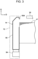
Fig. 3 is a cross-sectional view illustrating a supplier of the medium feeding device according to this exemplary embodiment; -
Fig. 4 is a cross-sectional view illustrating a state where air is being supplied to multiple sheet members in the configuration illustrated inFig. 3 ; -
Fig. 5 is a perspective view illustrating a projection unit and a camera according to this exemplary embodiment; -
Fig. 6 is a plan view illustrating the projection unit and the camera according to this exemplary embodiment; -
Fig. 7 is a side view illustrating the projection unit and the camera according to this exemplary embodiment; -
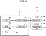
Fig. 8 is a block diagram illustrating a hardware configuration of a controller of the medium feeding device according to this exemplary embodiment; -
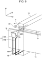
Fig. 9 is a perspective view illustrating the projection unit and the camera according to a modification; -
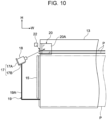
Fig. 10 is a side view illustrating the projection unit and the camera according to the modification; -
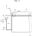
Fig. 11 is a side view illustrating a state where a sheet member is fed in the configuration illustrated inFig. 10 ; -
Fig. 12 is a plan view illustrating the projection unit and the camera according to a modification; -
Fig. 13 is a side view illustrating the projection unit and the camera according to another modification; and -
Fig. 14 is a side view illustrating a state where a sheet member is fed in the configuration illustrated inFig. 13 . - An example of an exemplary embodiment of the present disclosure will be described below with reference to the drawings. An arrow H denoted in each drawing indicates an up-down direction (vertical direction) of an apparatus, an arrow W indicates a width direction (horizontal direction) of the apparatus, and an arrow D indicates a depth direction (horizontal direction) of the apparatus.
- An
image forming apparatus 100 forms an image onto a sheet member P, and includes amedium feeding device 10 and animage forming unit 102, as illustrated inFig. 1 . Themedium feeding device 10 may be provided in advance in anapparatus body 101 of theimage forming apparatus 100, or may be optionally added and attached to theapparatus body 101 of theimage forming apparatus 100. The sheet member P is an example of a recording medium. - The
image forming unit 102 illustrated inFig. 1 is a component that forms an image onto the sheet member P fed from themedium feeding device 10. For example, theimage forming unit 102 used is of an electrophotographic type that forms an image onto the sheet member P by using toner. - An electrophotographic image forming unit forms an image onto the sheet member P by performing, for example, charging, exposure, developing, transfer, and fixing steps. In detail, for example, an electrophotographic image forming unit forms an image onto a transfer body by performing charging, exposure, developing, and transfer steps, transfers the image from the transfer body to the sheet member P, and subsequently fixes the image onto the sheet member P, thereby forming the image on the sheet member P.
- The example of the image forming unit is not limited to the electrophotographic image forming unit mentioned above, and may be any of various image forming units, such as an inkjet image forming unit. For example, an inkjet image forming unit forms an image onto the sheet member P by ejecting ink droplets from an ejector onto the sheet member P.
- The
medium feeding device 10 illustrated inFig. 1 feeds the sheet member P toward theimage forming unit 102. As illustrated inFig. 2 , themedium feeding device 10 includes aloading section 12 and afeeding unit 16. Furthermore, as illustrated inFigs. 2 ,3 , and4 , themedium feeding device 10 includes aside guide 13 and asupplier 14. Moreover, as illustrated inFigs. 5 ,6 , and7 , themedium feeding device 10 includes a leadingedge guide 15, aprojection unit 20, acamera 18, and alight source 22. In addition, as illustrated inFig. 8 , themedium feeding device 10 includes acontroller 40. Theside guide 13 is an example of a contact section. Thecamera 18 is an example of an image capturing unit. - The
loading section 12 is a component on which the sheet member P is loaded. As illustrated inFig. 2 , theloading section 12 includes abottom plate 12A on which multiple sheet members P are loaded in a stacked state in the up-down direction, and also includes an ascending-descending device (not illustrated) that causes thebottom plate 12A to ascend and descend in the up-down direction. The ascending-descending device causes thebottom plate 12A to ascend such that the position of an uppermost sheet member P of the sheet members P loaded on thebottom plate 12A is set at a predetermined height. - As illustrated in
Fig. 2 , theside guide 13 is a component that comes into contact with a lateral edge of the multiple sheet members P from a lateral side of the multiple sheet members P. In detail, theside guide 13 is disposed at each of opposite lateral edges of the sheet members P loaded on thebottom plate 12A. In other words, theside guide 13 is provided as a pair. The pair of side guides 13 come into contact with the opposite lateral edges (i.e., opposite edges of the sheet members P in the width direction (the direction of the arrow Y)) of the sheet members P loaded on thebottom plate 12A, so as to limit the position of the sheet members P in the width direction. - The pair of side guides 13 are movable toward the lateral sides of the sheet members P. In detail, the pair of side guides 13 are attached to a device body 11 (see
Fig. 1 ) of themedium feeding device 10 in a slidable manner in the depth direction serving as the width direction (see the direction of the arrow Y) of the sheet members P. In this exemplary embodiment, a user manually moves the side guides 13 in the width direction of the sheet members P in conformity with the widthwise size of the sheet members P, so that the side guides 13 come into contact with the opposite lateral edges of the sheet members P, thereby limiting the position of the sheet members P in the width direction. - As illustrated in
Figs. 6 and7 , the leadingedge guide 15 is a component that comes into contact with the leading edge of the multiple sheet members P from the downstream side (i.e., in the direction of an arrow W1 inFig. 2 ) in a feeding direction, to be described later, relative to the multiple sheet members P. In detail, the leadingedge guide 15 is disposed at the leading edge of the sheet members P loaded on thebottom plate 12A. Theleading edge guide 15 comes into contact with the leading edge (i.e., downstream edge in the feeding direction to be described later) of the sheet members P loaded on thebottom plate 12A, so as to limit the position of the sheet members P in the feeding direction (i.e., transport direction). - The
supplier 14 is a component that supplies air toward an edge of the multiple sheet members P loaded on theloading section 12 to cause the sheet members P to levitate, thereby separating the sheet members P from one another. As illustrated inFig. 2 , for example, thesupplier 14 is disposed inside one of the pair of side guides 13 (i.e., the front one in the depth direction D inFig. 2 ). As illustrated inFigs. 3 and4 , thesupplier 14 includes aduct 50 having asupply port 50A and ablower 54 that supplies air into theduct 50. - As illustrated in
Figs. 3 and4 , theduct 50 extends in the up-down direction. An area located at the upper end of theduct 50 and facing the loaded sheet members P is provided with thesupply port 50A. As illustrated inFigs. 3 and4 , theblower 54 is disposed below theduct 50 and supplies air into theduct 50. - As illustrated in
Fig. 4 , in thesupplier 14, the air supplied into theduct 50 by theblower 54 travels upward through theduct 50 and is supplied toward a lateral edge (i.e., an example of an edge) of the sheet members P via thesupply port 50A. Then, the air is supplied between upper sheet members P of the multiple loaded sheet members P, so that multiple sheet members P levitate and become separated from one another. - In this exemplary embodiment, the
supplier 14 supplies the air toward one lateral edge (i.e., the front one in the depth direction D inFig. 2 ) of the multiple sheet members P. However, the exemplary embodiment is not limited to this configuration. For example, as an alternative to or in addition to the one lateral edge (i.e., the front one in the depth direction D inFig. 2 ) of the multiple sheet members P, thesupplier 14 may supply the air toward at least one of the other lateral edge (i.e., the rear one in the depth direction D inFig. 2 ), the leading edge (i.e., the downstream edge in the feeding direction to be described later), and the trailing edge (i.e., the upstream edge in the feeding direction to be described later). - The
feeding unit 16 is a component that feeds, in the feeding direction (see the arrow W1 inFig. 2 ), an uppermost one of the sheet members P separated by thesupplier 14. In detail, as illustrated inFig. 2 , thefeeding unit 16 is disposed above the uppermost sheet member P of the multiple sheet members P loaded on thebottom plate 12A of theloading section 12. Thefeeding unit 16 includes asuction unit 30 and afeed roller 26. - The
suction unit 30 is disposed above a leading-edge area of the uppermost sheet member P in the loaded state. Thesuction unit 30 suctions the uppermost levitated sheet member P and moves the sheet member P in the suctioned state in the feeding direction (see the arrow W1 inFig. 2 ), thereby transporting the sheet member P in the feeding direction. - The
feed roller 26 is disposed in the feeding direction relative to thesuction unit 30, receives the sheet member P transported by thesuction unit 30, and feeds the received sheet member P toward the image forming unit 102 (seeFig. 1 ). - As illustrated in
Figs. 5 ,6 , and7 , theprojection unit 20 is a component that is provided at theside guide 13 and onto which an image of the lateral edge of the multiple sheet members P is projected in the feeding direction. In detail, theprojection unit 20 is constituted of a reflecting mirror serving as a reflector that reflects light from the lateral edge of the sheet members P in the feeding direction. - The
projection unit 20 receives the light from the lateral edge of the sheet members P and reflects the light in the feeding direction. Accordingly, the image of the lateral edge of the multiple sheet members P is projected onto theprojection unit 20 in the feeding direction. - For example, the
projection unit 20 is attached to theside guide 13 such that aprojection surface 20A onto which the image is projected is set at a 45-degree angle relative to the feeding direction and the width direction of the sheet members P. Furthermore, theprojection unit 20 is attachable to and detachable from theside guide 13. Theprojection unit 20 is attached to theside guide 13 in a detachable manner from theside guide 13. Accordingly, maintenance and inspection processes, including a cleaning process of theprojection surface 20A, may be executed on theprojection unit 20 in a state where theside guide 13 is attached to thedevice body 11 of themedium feeding device 10. - Furthermore, in this exemplary embodiment, the
side guide 13 is open in two directions relative to theprojection unit 20, namely, toward the downstream side in the feeding direction and toward the lateral edge of the sheet members P, and is closed in directions (i.e., other directions including the up-down direction) other than the two directions relative to theprojection unit 20. Therefore, light is inputtable to and outputtable from theprojection unit 20 in the two directions, namely, toward the downstream side in the feeding direction and toward the lateral edge of the sheet members P. - The
light source 22 is a component that radiates light onto the lateral edge of the multiple sheet members P loaded on theloading section 12. In this exemplary embodiment, for example, thelight source 22 is disposed alongside the lateral edge of the sheet members P, as well as downstream of theside guide 13 in the feeding direction and above the leading edge guide 15 (seeFigs. 6 and7 ). Thelight source 22 radiates light onto the lateral edge of the sheet members P from the aforementioned position where thelight source 22 is disposed. - Furthermore, the
light source 22 does not radiate the light onto theprojection surface 20A of theprojection unit 20 onto which the image is projected. In detail, the light traveling from thelight source 22 toward theprojection surface 20A is blocked by theside guide 13, so that the light is not radiated onto theprojection surface 20A from thelight source 22. Thelight source 22 is, for example, a light emitting element, such as a light emitting diode (LED). - The
camera 18 is a component that captures the image of the sheet members P projected on theprojection unit 20 in a state where the sheet members P are supplied with the air from thesupplier 14. As illustrated inFigs. 5 ,6 , and7 , thecamera 18 is disposed in the feeding direction relative to the multiple sheet members P. Moreover, thecamera 18 is disposed at a position where it does not interfere with each sheet member P fed by thefeeding unit 16. In detail, thecamera 18 is disposed alongside a position where a recording medium fed by thefeeding unit 16 passes (see P1 inFig. 6 ). In this exemplary embodiment, thecamera 18 is disposed at the same height as the position where the recording medium passes (see P1 inFig. 6 ). - Furthermore, the
camera 18 is coupled to theside guide 13 and moves together with theside guide 13. In other words, thecamera 18 moves laterally in conjunction with the movement of theside guide 13. - In detail, the
camera 18 is coupled to theside guide 13 by anattachment section 17 and acoupling member 19. Theattachment section 17 is a component to which thecamera 18 is attached. For example, theattachment section 17 has aside plate 17A that supports thecamera 18 from the feeding direction and abase plate 17B that supports thecamera 18 from below. - The
coupling member 19 has a pair ofarms 19A that are L-shaped in side view. One end (i.e., upper end) of eacharm 19A is fixed to thebase plate 17B, whereas the other end (i.e., upstream end in the feeding direction) of eacharm 19A is fixed to a lower area of theside guide 13. - Accordingly, the
camera 18 disposed in the feeding direction relative to the sheet members P loaded on theloading section 12 captures the image, as, for example, a still image, of the lateral edge of the sheet members P projected on theprojection unit 20 from the feeding direction relative to the sheet members P. - As illustrated in
Fig. 8 , thecontroller 40 has a central processing unit (CPU) 41, a read only memory (ROM) 42, a random access memory (RAM) 43, astorage unit 44, and a communication interface (IF) 45. These components are connected to one another in a communicable manner by abus 49. TheCPU 41 is an example of a processor. - The
CPU 41 is a central processing unit that executes various types of programs and controls each unit. TheROM 42 stores various types of programs, including a control program, and various types of data. TheRAM 43 serves as a work area that temporarily stores a program or data. Thestorage unit 44 is a hard disk drive (HDD), a solid state drive (SSD), or a storage medium, such as a flash memory, and stores various types of programs, including an operating system, and various types of data. The control program may alternatively be stored in thestorage unit 44. - The communication IF 45 is an interface via which the
controller 40 communicates with, for example, thecamera 18, thefeeding unit 16, the supplier 14 (i.e., the blower 54), and theimage forming unit 102. The standard used by the communication IF 45 is, for example, Ethernet (registered trademark), fiber distributed data interface (FDDI), or Wi-Fi (registered trademark). - In the
controller 40, theCPU 41 reads each type of program including the control program from theROM 42 or thestorage unit 44, and executes the program by using theRAM 43 as a work area. TheCPU 41 executes the control program so as to control the operation of thesupplier 14. In detail, in this exemplary embodiment, for example, in accordance with the distance between the sheet members P image-captured by thecamera 18, the supply amount of the supplier 14 (i.e., the blower 54) is adjusted, and the stoppage and activation of thesupplier 14 are controlled. - In this exemplary embodiment, as illustrated in
Figs. 5 ,6 , and7 , the image of the lateral edge of the multiple sheet members P is projected in the feeding direction by theprojection unit 20 provided at theside guide 13. Thecamera 18 captures the image of the sheet members P projected on theprojection unit 20 in a state where the sheet members P are supplied with the air from thesupplier 14. - Therefore, the degree of freedom with respect to the installation position of the
camera 18 may be enhanced, as compared with a case where thecamera 18 directly captures the image of the lateral edge of the multiple sheet members P. Furthermore, with this configuration, thecamera 18 is capable of capturing an image of an edge of the sheet members P in the feeding direction together with the image of the lateral edge of the sheet members P. - In this exemplary embodiment, the
camera 18 is disposed at the position where it does not interfere with each sheet member P fed by thefeeding unit 16. - Therefore, a feeding failure of each sheet member P may be suppressed, as compared with a case where the
camera 18 is disposed at a position where it interferes with each sheet member P fed by thefeeding unit 16. - In this exemplary embodiment, the
camera 18 is specifically disposed alongside the position where a recording medium fed by thefeeding unit 16 passes (see P1 inFig. 6 ). - Therefore, the degree of freedom with respect to the installation position of the
camera 18 in the up-down direction may be enhanced, as compared with a case where thecamera 18 is disposed above or below the position where each sheet member P fed by thefeeding unit 16 passes. In this configuration, thecamera 18 may be disposed at the same height as the position where each sheet member P fed by thefeeding unit 16 passes. - In this exemplary embodiment, the
camera 18 moves laterally in conjunction with the movement of theside guide 13. - Therefore, an out-of-focus state of the
camera 18 when thecamera 18 captures the image of the lateral edge of the multiple sheet members P projected on theprojection unit 20 may be suppressed, as compared with a case where thecamera 18 is always set at a fixed position. - In this exemplary embodiment, the
camera 18 is coupled to theside guide 13 and moves together with theside guide 13. - Therefore, an out-of-focus state of the
camera 18 when thecamera 18 captures the image of the lateral edge of the multiple sheet members P projected on theprojection unit 20 may be suppressed, as compared with a case where thecamera 18 is separated from theside guide 13 and moves independently therefrom. - In this exemplary embodiment, the
projection unit 20 is attachable to and detachable from theside guide 13. - Therefore, the
projection unit 20 may be cleaned readily, as compared with a case where theprojection unit 20 is fixed to theside guide 13 in a non-detachable manner. - In this exemplary embodiment, the
light source 22 radiates light onto the lateral edge of the multiple sheet members P loaded on theloading section 12 and does not radiate the light onto theprojection surface 20A of theprojection unit 20. - Therefore, as compared with a case where the
light source 22 also radiates the light onto theprojection surface 20A of theprojection unit 20, reflection of the light on theprojection surface 20A may be less likely to occur, and an image capturing failure occurring when thecamera 18 captures the image of the lateral edge of the multiple sheet members P projected on theprojection unit 20 may be suppressed. - Although the
camera 18 is used as an example of the image capturing unit in this exemplary embodiment, the configuration is not limited to this. For example, the image capturing unit may be a video camera that captures a video image so long as the image capturing unit is a component capable of capturing the image projected on theprojection unit 20. - Although a reflecting mirror is used as an example of the
projection unit 20 in this exemplary embodiment, the configuration is not limited to this. For example, theprojection unit 20 may be a prism so long as theprojection unit 20 is a component onto which the image of the lateral edge of the multiple sheet members P is projected in the feeding direction. - Although a light emitting element, such as an LED, is used as an example of the
light source 22 in this exemplary embodiment, the configuration is not limited to this. For example, thelight source 22 may be another light emitter that emits light so long as thelight source 22 is capable of radiating light onto the lateral edge of the multiple sheet members P. Furthermore, themedium feeding device 10 may be configured not to include thelight source 22. - In this exemplary embodiment, the
camera 18 is disposed alongside the position where a recording medium fed by thefeeding unit 16 passes (see P1 inFig. 6 ) and at the same height as the position where the recording medium passes (see P1 inFig. 6 ). However, the configuration is not limited to this. - For example, as illustrated in
Figs. 9 and10 , thecamera 18 may be disposed below the position where the recording medium passes (see P1 inFig. 6 ). In this case, in side view as illustrated inFig. 11 , each sheet member P fed by thefeeding unit 16 travels above thecamera 18. Moreover, in this case, in plan view as illustrated inFig. 12 , thecamera 18 may be disposed at a position aligned with the position where each sheet member P fed by thefeeding unit 16 passes. In other words, thecamera 18 may be disposed below the position where each sheet member P fed by thefeeding unit 16 passes. - Furthermore, as illustrated in
Fig. 13 , thecamera 18 may be disposed above the position where the recording medium passes (see P1 inFig. 6 ). In this case, in side view as illustrated inFig. 14 , each sheet member P fed by thefeeding unit 16 travels below thecamera 18. - Although the
camera 18 moves laterally in conjunction with the movement of theside guide 13 in this exemplary embodiment, the configuration is not limited to this. For example, thecamera 18 may be constantly set at a fixed position. In this case, for example, the image capturing angle (orientation) of thecamera 18 may be changed in accordance with the position of theprojection unit 20 after the movement of theside guide 13. - Although the
camera 18 is coupled to theside guide 13 and moves together with theside guide 13 in this exemplary embodiment, the configuration is not limited to this. For example, thecamera 18 may be separated from theside guide 13 and move independently therefrom. In this case, the movement of theside guide 13 and the amount of movement thereof may be detected by a detector, such as a sensor, and thecamera 18 may be moved by a driving force of a driver, such as a driving motor, based on the amount of movement detected by the detector, so that thecamera 18 moves in conjunction with the movement of theside guide 13. - Although the
projection unit 20 is attachable to and detachable from theside guide 13 in this exemplary embodiment, the configuration is not limited to this. For example, theprojection unit 20 may be fixed to theside guide 13 in a non-detachable manner. - In this exemplary embodiment, the
light source 22 radiates light onto the lateral edge of the multiple sheet members P loaded on theloading section 12 and does not radiate the light onto theprojection surface 20A of theprojection unit 20. However, the configuration is not limited to this. For example, thelight source 22 may also radiate the light onto theprojection surface 20A of theprojection unit 20. - The exemplary embodiment of the present disclosure is not limited to that described above, and various modifications, alterations, and improvements are possible so long as they do not depart from the scope of the exemplary embodiment of the present disclosure. For example, multiple modifications described above may be combined, where appropriate.
- In the exemplary embodiment above, the term "processor" refers to hardware in a broad sense. Examples of the processor include general processors (e.g., CPU: Central Processing Unit) and dedicated processors (e.g., GPU: Graphics Processing Unit, ASIC: Application Specific Integrated Circuit, FPGA: Field Programmable Gate Array, and programmable logic device).
- In the exemplary embodiment above, the term "processor" is broad enough to encompass one processor or plural processors in collaboration which are located physically apart from each other but may work cooperatively. The order of operations of the processor is not limited to one described in the embodiments above, and may be changed.
- The foregoing description of the exemplary embodiments of the present disclosure has been provided for the purposes of illustration and description. It is not intended to be exhaustive or to limit the disclosure to the precise forms disclosed. Obviously, many modifications and variations will be apparent to practitioners skilled in the art. The embodiments were chosen and described in order to best explain the principles of the disclosure and its practical applications, thereby enabling others skilled in the art to understand the disclosure for various embodiments and with the various modifications as are suited to the particular use contemplated. It is intended that the scope of the disclosure be defined by the following claims and their equivalents.
-
- (((1))) A medium feeding device comprising:
- a supplier that causes a plurality of loaded recording media to levitate and be separated from each other by supplying air to the recording media from an edge of the recording media;
- a feeding unit that feeds, in a feeding direction, an uppermost one of the recording media separated by the supplier;
- a contact section that comes into contact with a lateral edge of the plurality of recording media from a lateral side of the plurality of recording media;
- a projection unit that is provided at the contact section and onto which an image of the lateral edge of the plurality of recording media is projected in the feeding direction; and
- an image capturing unit that is disposed in the feeding direction relative to the plurality of recording media and that captures the image projected on the projection unit in a state where the plurality of recording media are supplied with the air from the supplier.
- (((2))) The medium feeding device according to (((1))),
wherein the image capturing unit is disposed at a position where the image capturing unit does not interfere with each recording medium fed by the feeding unit. - (((3))) The medium feeding device according to (((2))),
wherein the image capturing unit is disposed toward the lateral side relative to a position where each recording medium fed by the feeding unit passes. - (((4))) The medium feeding device according to any one of (((1))) to (((3))),
- wherein the contact section is movable toward the lateral side of the recording media, and
- wherein the image capturing unit moves toward the lateral side in conjunction with movement of the contact section.
- (((5))) The medium feeding device according to (((4))),
wherein the image capturing unit is coupled to the contact section and moves together with the contact section. - (((6))) The medium feeding device according to any one of (((1))) to (((5))),
wherein the projection unit is attachable to and detachable from the contact section. - (((7))) The medium feeding device according to any one of (((1))) to (((6))), further comprising:
a light source that radiates light onto the lateral edge of the plurality of loaded recording media and does not radiate the light onto a projection surface of the projection unit onto which the image is projected. - (((8))) An image forming apparatus comprising:
- the medium feeding device according to any one of (((1))) to (((7))); and
- an image forming unit that forms an image onto each recording medium fed from the medium feeding device.
- In the configuration according to (((1))), the degree of freedom with respect to the installation position of the image capturing unit may be enhanced, as compared with a case where the image capturing unit directly captures the image of the lateral edge of the plurality of recording media.
- In the configuration according to (((2))), a feeding failure of each recording medium may be suppressed, as compared with a case where the image capturing unit is disposed at a position where it interferes with each recording medium fed by the feeding unit.
- In the configuration according to (((3))), the degree of freedom with respect to the installation position of the image capturing unit in the up-down direction may be enhanced, as compared with a case where the image capturing unit is disposed above or below the position where each recording medium fed by the feeding unit passes.
- In the configuration according to (((4))), an out-of-focus state of the image capturing unit when the image capturing unit captures the image of the lateral edge of the plurality of recording media projected on the projection unit may be suppressed, as compared with a case where the image capturing unit is always set at a fixed position.
- In the configuration according to (((5))), an out-of-focus state of the image capturing unit when the image capturing unit captures the image of the lateral edge of the plurality of recording media projected on the projection unit may be suppressed, as compared with a case where the image capturing unit is separated from the contact section and moves independently therefrom.
- In the configuration according to (((6))), the projection unit may be cleaned readily, as compared with a case where the projection unit is fixed to the contact section in a non-detachable manner.
- In the configuration according to (((7))), an image capturing failure occurring when the image capturing unit captures the image of the lateral edge of the plurality of recording media projected on the projection unit may be suppressed, as compared with a case where the light source also radiates the light onto the projection surface of the projection unit.
Claims (8)
- A medium feeding device comprising:a supplier that causes a plurality of loaded recording media to levitate and be separated from each other by supplying air to the recording media from an edge of the recording media;a feeding unit that feeds, in a feeding direction, an uppermost one of the recording media separated by the supplier;a contact section that comes into contact with a lateral edge of the plurality of recording media from a lateral side of the plurality of recording media;a projection unit that is provided at the contact section and onto which an image of the lateral edge of the plurality of recording media is projected in the feeding direction; andan image capturing unit that is disposed in the feeding direction relative to the plurality of recording media and that captures the image projected on the projection unit in a state where the plurality of recording media are supplied with the air from the supplier.
- The medium feeding device according to claim 1,
wherein the image capturing unit is disposed at a position where the image capturing unit does not interfere with each recording medium fed by the feeding unit. - The medium feeding device according to claim 2,
wherein the image capturing unit is disposed toward the lateral side relative to a position where each recording medium fed by the feeding unit passes. - The medium feeding device according to any one of claims 1 to 3,wherein the contact section is movable toward the lateral side of the recording media, andwherein the image capturing unit moves toward the lateral side in conjunction with movement of the contact section.
- The medium feeding device according to claim 4,
wherein the image capturing unit is coupled to the contact section and moves together with the contact section. - The medium feeding device according to any one of claims 1 to 5,
wherein the projection unit is attachable to and detachable from the contact section. - The medium feeding device according to any one of claims 1 to 6, further comprising:
a light source that radiates light onto the lateral edge of the plurality of loaded recording media and does not radiate the light onto a projection surface of the projection unit onto which the image is projected. - An image forming apparatus comprising:the medium feeding device according to any one of claims 1 to 7; andan image forming unit that forms an image onto each recording medium fed from the medium feeding device.
Applications Claiming Priority (1)
| Application Number | Priority Date | Filing Date | Title |
|---|---|---|---|
| JP2023161518A JP2025052683A (en) | 2023-09-25 | 2023-09-25 | Medium delivery device and image forming device |
Publications (1)
| Publication Number | Publication Date |
|---|---|
| EP4527768A1 true EP4527768A1 (en) | 2025-03-26 |
Family
ID=90059499
Family Applications (1)
| Application Number | Title | Priority Date | Filing Date |
|---|---|---|---|
| EP24159542.0A Pending EP4527768A1 (en) | 2023-09-25 | 2024-02-26 | Medium feeding device and image forming apparatus |
Country Status (4)
| Country | Link |
|---|---|
| US (1) | US20250100825A1 (en) |
| EP (1) | EP4527768A1 (en) |
| JP (1) | JP2025052683A (en) |
| CN (1) | CN119689810A (en) |
Citations (4)
| Publication number | Priority date | Publication date | Assignee | Title |
|---|---|---|---|---|
| US20110233270A1 (en) * | 2010-03-26 | 2011-09-29 | Xerox Corporation | Method and apparatus for sheet feeding from a media stack using a bar code scanning device in an image production device |
| US20140191461A1 (en) * | 2013-01-10 | 2014-07-10 | Konica Minolta, Inc. | Sheet feeding device and image forming apparatus |
| US9272863B2 (en) * | 2013-03-18 | 2016-03-01 | Konica Minolta, Inc. | Sheet feeding device and image forming apparatus |
| JP2020152535A (en) | 2019-03-20 | 2020-09-24 | 株式会社リコー | Sheet feeding device and image forming device |
-
2023
- 2023-09-25 JP JP2023161518A patent/JP2025052683A/en active Pending
-
2024
- 2024-02-21 CN CN202410192318.8A patent/CN119689810A/en active Pending
- 2024-02-26 US US18/586,667 patent/US20250100825A1/en active Pending
- 2024-02-26 EP EP24159542.0A patent/EP4527768A1/en active Pending
Patent Citations (4)
| Publication number | Priority date | Publication date | Assignee | Title |
|---|---|---|---|---|
| US20110233270A1 (en) * | 2010-03-26 | 2011-09-29 | Xerox Corporation | Method and apparatus for sheet feeding from a media stack using a bar code scanning device in an image production device |
| US20140191461A1 (en) * | 2013-01-10 | 2014-07-10 | Konica Minolta, Inc. | Sheet feeding device and image forming apparatus |
| US9272863B2 (en) * | 2013-03-18 | 2016-03-01 | Konica Minolta, Inc. | Sheet feeding device and image forming apparatus |
| JP2020152535A (en) | 2019-03-20 | 2020-09-24 | 株式会社リコー | Sheet feeding device and image forming device |
Also Published As
| Publication number | Publication date |
|---|---|
| CN119689810A (en) | 2025-03-25 |
| JP2025052683A (en) | 2025-04-07 |
| US20250100825A1 (en) | 2025-03-27 |
Similar Documents
| Publication | Publication Date | Title |
|---|---|---|
| US10723153B2 (en) | Inkjet printing apparatus | |
| US20180327202A1 (en) | Sheet feeding device and image forming device | |
| US11084287B2 (en) | Printing apparatus, control method thereof and storage medium | |
| US20250100825A1 (en) | Medium feeding device and image forming apparatus | |
| EP4527767B1 (en) | Medium loading system and image forming system | |
| JP4750685B2 (en) | Sheet feeding apparatus and image forming apparatus | |
| US20240425313A1 (en) | Medium supply system and image forming system | |
| US12240722B2 (en) | Feeding device and image forming apparatus | |
| US20240101376A1 (en) | Medium supply device and image forming apparatus | |
| US11319175B2 (en) | Sheet feeding device, image forming apparatus incorporating the sheet feeding device, and image forming system incorporating the sheet feeding device | |
| US20250100824A1 (en) | Medium stacking device and image forming apparatus | |
| CN111285143A (en) | Sheet loading device and image forming system | |
| US12421064B2 (en) | Feeding device and image forming apparatus | |
| JP5206326B2 (en) | Image forming apparatus, conveyance control method by image forming apparatus, and conveyance control program | |
| JP7826791B2 (en) | Sending device and image forming device | |
| US20250001772A1 (en) | Medium supply system and image forming system | |
| US20250071214A1 (en) | Medium accommodating device and image forming system | |
| CN112753292B (en) | component supply device | |
| US20160221368A1 (en) | Recording apparatus | |
| US20150273886A1 (en) | Liquid ejecting apparatus | |
| US20240101371A1 (en) | Medium supply device and image forming apparatus | |
| US20250033910A1 (en) | Medium accommodating device and image forming system | |
| US20160246236A1 (en) | Image Forming Apparatus | |
| JP2021183542A (en) | Medium supply device | |
| JP2007269409A (en) | Sheet feeding apparatus and image forming apparatus |
Legal Events
| Date | Code | Title | Description |
|---|---|---|---|
| PUAI | Public reference made under article 153(3) epc to a published international application that has entered the european phase |
Free format text: ORIGINAL CODE: 0009012 |
|
| STAA | Information on the status of an ep patent application or granted ep patent |
Free format text: STATUS: THE APPLICATION HAS BEEN PUBLISHED |
|
| AK | Designated contracting states |
Kind code of ref document: A1 Designated state(s): AL AT BE BG CH CY CZ DE DK EE ES FI FR GB GR HR HU IE IS IT LI LT LU LV MC ME MK MT NL NO PL PT RO RS SE SI SK SM TR |
|
| STAA | Information on the status of an ep patent application or granted ep patent |
Free format text: STATUS: REQUEST FOR EXAMINATION WAS MADE |
|
| 17P | Request for examination filed |
Effective date: 20250429 |