EP4527760A2 - A remotely operated vehicle with an arrangement to provide a pre-alert and tracking of a position of the vehicle - Google Patents
A remotely operated vehicle with an arrangement to provide a pre-alert and tracking of a position of the vehicle Download PDFInfo
- Publication number
- EP4527760A2 EP4527760A2 EP25156493.6A EP25156493A EP4527760A2 EP 4527760 A2 EP4527760 A2 EP 4527760A2 EP 25156493 A EP25156493 A EP 25156493A EP 4527760 A2 EP4527760 A2 EP 4527760A2
- Authority
- EP
- European Patent Office
- Prior art keywords
- vehicle
- sensor
- rails
- sensor module
- sensors
- Prior art date
- Legal status (The legal status is an assumption and is not a legal conclusion. Google has not performed a legal analysis and makes no representation as to the accuracy of the status listed.)
- Pending
Links
Images



Classifications
-
- B—PERFORMING OPERATIONS; TRANSPORTING
- B65—CONVEYING; PACKING; STORING; HANDLING THIN OR FILAMENTARY MATERIAL
- B65G—TRANSPORT OR STORAGE DEVICES, e.g. CONVEYORS FOR LOADING OR TIPPING, SHOP CONVEYOR SYSTEMS OR PNEUMATIC TUBE CONVEYORS
- B65G1/00—Storing articles, individually or in orderly arrangement, in warehouses or magazines
- B65G1/02—Storage devices
- B65G1/04—Storage devices mechanical
- B65G1/0464—Storage devices mechanical with access from above
-
- G—PHYSICS
- G05—CONTROLLING; REGULATING
- G05D—SYSTEMS FOR CONTROLLING OR REGULATING NON-ELECTRIC VARIABLES
- G05D1/00—Control of position, course, altitude or attitude of land, water, air or space vehicles, e.g. using automatic pilots
- G05D1/02—Control of position or course in two dimensions
-
- B—PERFORMING OPERATIONS; TRANSPORTING
- B65—CONVEYING; PACKING; STORING; HANDLING THIN OR FILAMENTARY MATERIAL
- B65G—TRANSPORT OR STORAGE DEVICES, e.g. CONVEYORS FOR LOADING OR TIPPING, SHOP CONVEYOR SYSTEMS OR PNEUMATIC TUBE CONVEYORS
- B65G1/00—Storing articles, individually or in orderly arrangement, in warehouses or magazines
- B65G1/02—Storage devices
- B65G1/04—Storage devices mechanical
-
- B—PERFORMING OPERATIONS; TRANSPORTING
- B65—CONVEYING; PACKING; STORING; HANDLING THIN OR FILAMENTARY MATERIAL
- B65G—TRANSPORT OR STORAGE DEVICES, e.g. CONVEYORS FOR LOADING OR TIPPING, SHOP CONVEYOR SYSTEMS OR PNEUMATIC TUBE CONVEYORS
- B65G1/00—Storing articles, individually or in orderly arrangement, in warehouses or magazines
- B65G1/02—Storage devices
- B65G1/04—Storage devices mechanical
- B65G1/0478—Storage devices mechanical for matrix-arrangements
-
- B—PERFORMING OPERATIONS; TRANSPORTING
- B65—CONVEYING; PACKING; STORING; HANDLING THIN OR FILAMENTARY MATERIAL
- B65G—TRANSPORT OR STORAGE DEVICES, e.g. CONVEYORS FOR LOADING OR TIPPING, SHOP CONVEYOR SYSTEMS OR PNEUMATIC TUBE CONVEYORS
- B65G1/00—Storing articles, individually or in orderly arrangement, in warehouses or magazines
- B65G1/02—Storage devices
- B65G1/04—Storage devices mechanical
- B65G1/137—Storage devices mechanical with arrangements or automatic control means for selecting which articles are to be removed
- B65G1/1373—Storage devices mechanical with arrangements or automatic control means for selecting which articles are to be removed for fulfilling orders in warehouses
-
- B—PERFORMING OPERATIONS; TRANSPORTING
- B65—CONVEYING; PACKING; STORING; HANDLING THIN OR FILAMENTARY MATERIAL
- B65G—TRANSPORT OR STORAGE DEVICES, e.g. CONVEYORS FOR LOADING OR TIPPING, SHOP CONVEYOR SYSTEMS OR PNEUMATIC TUBE CONVEYORS
- B65G1/00—Storing articles, individually or in orderly arrangement, in warehouses or magazines
- B65G1/02—Storage devices
- B65G1/04—Storage devices mechanical
- B65G1/137—Storage devices mechanical with arrangements or automatic control means for selecting which articles are to be removed
- B65G1/1373—Storage devices mechanical with arrangements or automatic control means for selecting which articles are to be removed for fulfilling orders in warehouses
- B65G1/1378—Storage devices mechanical with arrangements or automatic control means for selecting which articles are to be removed for fulfilling orders in warehouses the orders being assembled on fixed commissioning areas remote from the storage areas
-
- G—PHYSICS
- G01—MEASURING; TESTING
- G01S—RADIO DIRECTION-FINDING; RADIO NAVIGATION; DETERMINING DISTANCE OR VELOCITY BY USE OF RADIO WAVES; LOCATING OR PRESENCE-DETECTING BY USE OF THE REFLECTION OR RERADIATION OF RADIO WAVES; ANALOGOUS ARRANGEMENTS USING OTHER WAVES
- G01S17/00—Systems using the reflection or reradiation of electromagnetic waves other than radio waves, e.g. lidar systems
- G01S17/02—Systems using the reflection of electromagnetic waves other than radio waves
- G01S17/06—Systems determining position data of a target
- G01S17/46—Indirect determination of position data
-
- G—PHYSICS
- G05—CONTROLLING; REGULATING
- G05B—CONTROL OR REGULATING SYSTEMS IN GENERAL; FUNCTIONAL ELEMENTS OF SUCH SYSTEMS; MONITORING OR TESTING ARRANGEMENTS FOR SUCH SYSTEMS OR ELEMENTS
- G05B19/00—Program-control systems
- G05B19/02—Program-control systems electric
- G05B19/18—Numerical control [NC], i.e. automatically operating machines, in particular machine tools, e.g. in a manufacturing environment, so as to execute positioning, movement or co-ordinated operations by means of program data in numerical form
- G05B19/19—Numerical control [NC], i.e. automatically operating machines, in particular machine tools, e.g. in a manufacturing environment, so as to execute positioning, movement or co-ordinated operations by means of program data in numerical form characterised by positioning or contouring control systems, e.g. to control position from one programmed point to another or to control movement along a programmed continuous path
-
- G—PHYSICS
- G05—CONTROLLING; REGULATING
- G05D—SYSTEMS FOR CONTROLLING OR REGULATING NON-ELECTRIC VARIABLES
- G05D1/00—Control of position, course, altitude or attitude of land, water, air or space vehicles, e.g. using automatic pilots
- G05D1/20—Control system inputs
- G05D1/22—Command input arrangements
- G05D1/221—Remote-control arrangements
- G05D1/225—Remote-control arrangements operated by off-board computers
-
- G—PHYSICS
- G05—CONTROLLING; REGULATING
- G05D—SYSTEMS FOR CONTROLLING OR REGULATING NON-ELECTRIC VARIABLES
- G05D1/00—Control of position, course, altitude or attitude of land, water, air or space vehicles, e.g. using automatic pilots
- G05D1/20—Control system inputs
- G05D1/24—Arrangements for determining position or orientation
- G05D1/243—Means capturing signals occurring naturally from the environment, e.g. ambient optical, acoustic, gravitational or magnetic signals
-
- G—PHYSICS
- G05—CONTROLLING; REGULATING
- G05D—SYSTEMS FOR CONTROLLING OR REGULATING NON-ELECTRIC VARIABLES
- G05D1/00—Control of position, course, altitude or attitude of land, water, air or space vehicles, e.g. using automatic pilots
- G05D1/40—Control within particular dimensions
- G05D1/43—Control of position or course in two dimensions [2D]
-
- B—PERFORMING OPERATIONS; TRANSPORTING
- B65—CONVEYING; PACKING; STORING; HANDLING THIN OR FILAMENTARY MATERIAL
- B65G—TRANSPORT OR STORAGE DEVICES, e.g. CONVEYORS FOR LOADING OR TIPPING, SHOP CONVEYOR SYSTEMS OR PNEUMATIC TUBE CONVEYORS
- B65G2201/00—Indexing codes relating to handling devices, e.g. conveyors, characterised by the type of product or load being conveyed or handled
- B65G2201/02—Articles
- B65G2201/0235—Containers
-
- G—PHYSICS
- G05—CONTROLLING; REGULATING
- G05D—SYSTEMS FOR CONTROLLING OR REGULATING NON-ELECTRIC VARIABLES
- G05D2105/00—Specific applications of the controlled vehicles
- G05D2105/20—Specific applications of the controlled vehicles for transportation
- G05D2105/28—Specific applications of the controlled vehicles for transportation of freight
-
- G—PHYSICS
- G05—CONTROLLING; REGULATING
- G05D—SYSTEMS FOR CONTROLLING OR REGULATING NON-ELECTRIC VARIABLES
- G05D2107/00—Specific environments of the controlled vehicles
- G05D2107/70—Industrial sites, e.g. warehouses or factories
-
- G—PHYSICS
- G05—CONTROLLING; REGULATING
- G05D—SYSTEMS FOR CONTROLLING OR REGULATING NON-ELECTRIC VARIABLES
- G05D2109/00—Types of controlled vehicles
- G05D2109/10—Land vehicles
- G05D2109/14—Land vehicles moving on a grid
-
- G—PHYSICS
- G05—CONTROLLING; REGULATING
- G05D—SYSTEMS FOR CONTROLLING OR REGULATING NON-ELECTRIC VARIABLES
- G05D2111/00—Details of signals used for control of position, course, altitude or attitude of land, water, air or space vehicles
- G05D2111/10—Optical signals
Definitions
- Fig. 1 discloses a typical prior art automated storage and retrieval system 1 with a framework structure 100 and Fig. 2 and 3 disclose two different prior art container handling vehicles 201,301 suitable for operating on such a system 1.
- the framework structure 100 comprises upright members 102, horizontal members 103 and a storage volume comprising storage columns 105 arranged in rows between the upright members 102 and the horizontal members 103.
- storage columns 105 storage containers 106, also known as bins, are stacked one on top of one another to form stacks 107.
- the members 102, 103 may typically be made of metal, e.g. extruded aluminum profiles.
- Each prior art container handling vehicle 201,301 comprises a vehicle body 201a,301a, and first and second sets of wheels 201b,301b,201c,301c which enable the lateral movement of the container handling vehicles 201,301 in the X direction and in the Y direction, respectively.
- first and second sets of wheels 201b,301b,201c,301c which enable the lateral movement of the container handling vehicles 201,301 in the X direction and in the Y direction, respectively.
- the first set of wheels 201b,301b is arranged to engage with two adjacent rails of the first set 110 of rails
- the second set of wheels 201c,301c is arranged to engage with two adjacent rails of the second set 111 of rails.
- At least one of the sets of wheels 201b,301b,201c,301c can be lifted and lowered, so that the first set of wheels 201b,301b and/or the second set of wheels 201c,301c can be engaged with the respective set of rails 110, 111 at any one time.
- Each prior art container handling vehicle 201,301 also comprises a lifting device (not shown) for vertical transportation of storage containers 106, e.g. raising a storage container 106 from, and lowering a storage container 106 into, a storage column 105.
- the lifting device comprises one or more gripping / engaging devices which are adapted to engage a storage container 106, and which gripping / engaging devices can be lowered from the vehicle 201,301 so that the position of the gripping / engaging devices with respect to the vehicle 201,301 can be adjusted in a third direction Z which is orthogonal the first direction X and the second direction Y.
- Parts of the gripping device of the container handling vehicle 301 are shown in fig. 3 indicated with reference number 304.
- the gripping device of the container handling device 201 is located within the vehicle body 301a in Fig. 2 .
- the central cavity container handling vehicles 201 shown in Fig. 2 may have a footprint that covers an area with dimensions in the X and Y directions which is generally equal to the lateral extent of a storage column 105, e.g. as is described in WO2015/193278A1 , the contents of which are incorporated herein by reference.
- the term 'lateral' used herein may mean 'horizontal'.
- the rail system 108 typically comprises rails with grooves in which the wheels of the vehicles run.
- the rails may comprise upwardly protruding elements, where the wheels of the vehicles comprise flanges to prevent derailing. These grooves and upwardly protruding elements are collectively known as tracks.
- Each rail may comprise one track, or each rail may comprise two parallel tracks.
- WO2018146304 illustrates a typical configuration of rail system 108 comprising rails and parallel tracks in both X and Y directions.
- the first port column 119 may for example be a dedicated drop-off port column where the container handling vehicles 201,301 can drop off storage containers 106 to be transported to an access or a transfer station
- the second port column 120 may be a dedicated pick-up port column where the container handling vehicles 201,301 can pick up storage containers 106 that have been transported from an access or a transfer station.
- the access station may typically be a picking or a stocking station where product items are removed from or positioned into the storage containers 106.
- the storage containers 106 are normally not removed from the automated storage and retrieval system 1 but are returned into the framework structure 100 again once accessed.
- a port can also be used for transferring storage containers to another storage facility (e.g. to another framework structure or to another automated storage and retrieval system), to a transport vehicle (e.g. a train or a lorry), or to a production facility.
- the conveyor system may comprise a lift device with a vertical component for transporting the storage containers 106 vertically between the port column 119,120 and the access station.
- the automated storage and retrieval system 1 may have container handling vehicles specifically dedicated to the task of temporarily removing storage containers from a storage column 105. Once the target storage container 106 has been removed from the storage column 105, the temporarily removed storage containers can be repositioned into the original storage column 105. However, the removed storage containers may alternatively be relocated to other storage columns.
- one of the container handling vehicles 201,301 When a storage container 106 is to be stored in one of the columns 105, one of the container handling vehicles 201,301 is instructed to pick up the storage container 106 from the pick-up port column 120 and transport it to a location above the storage column 105 where it is to be stored. After any storage containers positioned at or above the target position within the storage column stack 107 have been removed, the container handling vehicle 201,301 positions the storage container 106 at the desired position. The removed storage containers may then be lowered back into the storage column 105 or relocated to other storage columns.
- the positions of a vehicle can be acquired in different ways.
- One way is to track the position of the vehicle relative to the tracks on top of the frame structure.
- the position can be acquired by means of tracking devices located externally to the vehicle or by devices integrated in the vehicle.
- Another method of tracking the position of the vehicle is by the integrated tracking devices to track the number of crossings passed in x- and y-directions relative to the tracks laid out as a grid structure.
- Integrated tracking devices By using integrated tracking devices, the vehicle itself will be able to keep track of its position. Integrated tracking devices are however quite complex systems and not necessarily very precise.
- Publication WO2018/082972 A1 describes a method and a remotely operated vehicle for tracking the position of the vehicle following a set route relative to tracks laid out on a frame structure forming a grid.
- An object of the present invention is to provide a precise tracking and confirmation of the position of the vehicle while situated on a grid cell.
- Another object of the present invention is to provide a vehicle with a pre-alert arrangement informing of the remaining distance until it reaches a set position, during which the vehicle may react.
- the invention is directed to a remotely operated vehicle with an apparatus to provide a pre-alert and tracking of a position of the vehicle following a travelling route relative to tracks laid out on a rail structure in x, y directions on a rail system.
- the vehicle having first and seconds sets of wheels connected to drives for moving the vehicle in corresponding x, y directions on the rail system.
- the remotely operated vehicle also referred to as the vehicle, may be a container handling vehicle or a delivery vehicle configured for operating on the rail system.
- the arrangement comprises at least three sensors:
- the position being a set position of the travelling route on tracks laid out on the rail structure in x, y directions on the rail system.
- the rail is also referred to as the rail structure.
- the sensors may be directed downward with an angle such that they may detect tracks and/or rails in any of the x-or y-direction.
- the sensors may be directed vertically downward such that they detect rail structures of the rail system.
- the first sensor, the second sensor and the third sensor may be arranged in a sensor module.
- the sensor module may be mounted into the structure of the vehicle in a corner position at least partly behind the wheels of the vehicle.
- the first sensor or the second sensor may detect a rail structure in the corresponding travelling direction, and pre-alert a remaining distance to the set position.
- the first and second sensors may detect their respective rails and conforms the vehicle being in the set position. If for instance, any of the first or second sensors does not detect their respective rails, the controller will notice that the vehicle is not precisely in the set position.
- the third sensor will not detect any obstacle since it is located in the corner at the intersection between the rails in the x-direction and y-direction. If however, the third sensor, in the set position, detects a rail structure, then the controller would know that the vehicle is not precisely in the set position.
- the arrangement may comprise two sensor modules; a first sensor module arranged in the corner position of the vehicle, and a second sensor module arranged at a diametrically opposite a corner position of the vehicle such that the corresponding sensors of the first and second sensor module are equally spaced from their corner position.
- the first sensor module may be defined as the front sensor in relation to the travelling direction of the vehicle, and the second sensor module may be defined as the back sensor module.
- Each of the first and second sensor module may comprise the at least three sensors; the first, the second and the third sensors, each directed/pointed vertically down towards the rails for determining the position of the vehicle.
- the sensors are arranged to register any obstacle breaking the beam such that a controller may notice every time the vehicle is passing a rail in the x-or y-direction.
- the third sensor may be located on respective first and second sensor module, such that the third sensor of the second sensor module, may pre-alert the remaining distance to the set position when moving in x-or y-direction.
- the controller would know that the remaining distance for the vehicle to travel to the set position, corresponds to the width of the rail structure.
- the output of the sensor may be used in a feedback loop in a controller for providing signals causing additional or less deceleration of the vehicle.
- the arrangement may further comprise a fourth sensor configured to pre-alert a remaining distance to the arrival of the vehicle at the position, by detecting any of the rails in the x-or y-direction.
- the fourth sensor position may be located such that it detects a rail when the vehicle is moving towards the set position. According to the location of the fourth sensor relative to the vehicle, the sensor may detect and pre-alert a predefined remaining distance to the set position. For instance, if the preferable pre-alert distance is 10 cm prior to arrival of the vehicle in the set position, the fourth sensor is located accordingly relative to the vehicle.
- the output of the fourth sensor may be used in a feedback loop in a controller for providing signals causing additional or less deceleration of the vehicle.
- the fourth sensor may be arranged in the sensor module together with the first, second and third sensors. All sensors may be provided in the sensor module which may be adapted to plug into the structure of the vehicle behind the wheels.
- Each of the first and second sensor module may comprise the first, second, third and fourth sensor.
- the first and second sensor module may be the same module but arranged to be mounted at diametrically opposite corners of the vehicle.
- the first and second module may be mounted into the structure of the vehicle and at least partly behind the wheels of the vehicle at diametrically opposite corners of the vehicle, such that the corresponding sensors of the first and second module are equally spaced from the corner position.
- the first and sensor module needs to be of a sufficient surface area to support all four sensors, the sensors being spaced as necessary with respect to underside of the vehicle. Any variations in how the modules attach to the vehicles could have knock-on effects for the accuracy of the sensors and the ability of the signals to provide reliable positional data.
- the module may be mounted onto the underside of the vehicle nested into a right-angled corner of the vehicle base, which will help to ensure that the module is accurately mounted with respect to the vehicle.
- all the sensors being mounted and fixed within the body of the module will mean that the relative position of the sensors can be accurately adhered to, once the mounted position of the module can be ensured.
- the sensors may also be able to share some of the signal processing electronics.
- Each of the four sensors of the first and second sensor module may be configured to pre-alert a remaining distance to the arrival of the vehicle at the position, by detecting any of the rail structure in the x-or y-direction.
- the output of any of the first, second, third or fourth sensors are used in a feedback loop in a controller for providing signals causing additional or less deceleration of the vehicle.
- the additional or less deceleration may be provided as necessary based on a predetermined or model of the change of speed profile stored in the controller's memory.
- the vehicle may have different mass (weight) between loaded and unloaded storage containers, the change in the momentum required may be hard to predict accurately. Therefore, the signals the sensors give during the acceleration phase may provide information whether the vehicle has picked up a heavy or a light storage container. This information may be used in the deceleration phase to guide the vehicle to a more accurate stop.
- the sensors may be optical sensors detecting reflection of lights from the rails.
- Other or additional sensors for detecting the rails and/or tracks for determining the position and pre-alert may also be used, e.g. acoustic sensors.
- a sensor having a narrow beam may be advantageous for the signal it will need to output in order to provide a stronger peak/trough signal.
- the vehicle may further comprise means for receiving instructions with information of the number of rails crossings to pass between start and stop positions in x- and y-directions according to the set route.
- Light is reflected from rails when a vehicle is moving along the tracks in x- or y-directions.
- the vehicle When the vehicle is passing a rail in any of the x-or y-direction the light will be reflected such that the controller receives information of the rail passing.
- the vehicle may further comprise a controller for controlling the drives of the vehicle according to the number of rails in x-and y-direction passed. When this is close to the total number of rails to pass between the start and stop positions in respective x- and y-directions along the set route, the controller may initiate deceleration of the vehicle.
- the signal transmitted to the controller can be used for performing precise control of deceleration and acceleration of the vehicle for following a set route along x- and y-directions.
- the controller may for example control precise deceleration of the vehicle prior to the next rail crossing where it is to change direction.
- the sensors attached to the vehicle and detecting means comprised in the vehicle may detect the number of rails and track crossings passed in each direction. When the number of passed crossings is close to the total number of rail crossings to pass on each leg, a signal is transmitted to the controller controlling the movements of the vehicle. In this way, the controller will know exactly when deceleration should start, as well as the rate and duration of acceleration.
- Each sensor module 81,82 comprises four sensors; a first sensor 83 directed to the rail in the x-direction 110, a second sensor 84 directed to the rail in the y-direction 111, a third sensor 85 directed to a corner of an intersection between the rail structure in the x-direction and y-direction 110,111, and a forth sensor 86 configured to pre-alert a remaining distance to the arrival of the vehicle at the position, by detecting the rail structure in the x or y direction 110,111.
- the first 83 and second 84 sensor are spaced from the corner position so that they may detect the rails in respective the x- and y-direction 110,111.
- Each of the first and second sensor module 81.82 may be equally spaced from the corner position on the vehicle 201,301.
- the first sensor 83 While moving in the x-direction of the rail system 110 towards a set location on a grid cell 122, the first sensor 83 detects the rails in the x-direction 110 continuously as the vehicle 201,301 moves along rails in the x-direction.
- the fourth sensor 86 of the second sensor module 82 is located such that when the sensor 86 detects the rail structure in the y-direction 111 of the grid cell 122 of the set position, it sends a signal to a controller so as to pre-alert the remaining distance to the set position.
- the remaining distance to the set position is defined by the position of the fourth sensor 86 relative to the vehicle 201,301. As shown in figure 9 , the remaining distance may be set to about 10 cm. Any pre-preferable distance may be obtained by moving the location of the fourth sensor 86, relative to the vehicle.
- the first sensor 83 of the first and second sensor module 81,82 detects the rails in the x-direction 110
- the second sensor 84 of the first and second sensor 81,82 detects the rails in the y-direction 111
- the third sensor 85 of the first and second sensor 81,82 detects no obstacles since it is located in the corner at the intersection between the rail structure in the x-direction and y-direction 110,111. If the third sensor 85 should detect an obstacle (i.e. a rail structure), then the controller would know that the vehicle 201,301 is located in an offset position (hence, not correctly at the set position on the grid cell).
- the first, second and third sensors 83,84,85 detects and confirms the position of the vehicle 201,301.
- sensors 83,84,85,86 of the first and second sensor system 81,82 will work the same way when the vehicle 201,301 is moving in the opposite x-direction of the rail system 108.
- the first sensor module 81 may be defined as the front sensor module in the moving direction of the vehicle 201,301. Such that when the vehicle 201,301 moves in opposite direction, the previous second sensor module 82 becomes the first sensor module 81.
- Figure 11 shows the first sensor module 81 and the second sensor module 82 dependent of the direction of travel for the vehicle 201,301.
- the sensor modules 81,82 are arranged at a diametrically opposite a corner position of the vehicle 201,301.
- Each of the sensor modules 81,82 may be the first sensor module 81, depending on the moving direction of the vehicle 201,301.
Landscapes
- Engineering & Computer Science (AREA)
- Physics & Mathematics (AREA)
- Mechanical Engineering (AREA)
- General Physics & Mathematics (AREA)
- Automation & Control Theory (AREA)
- Remote Sensing (AREA)
- Radar, Positioning & Navigation (AREA)
- Aviation & Aerospace Engineering (AREA)
- Human Computer Interaction (AREA)
- Manufacturing & Machinery (AREA)
- Mathematical Physics (AREA)
- Electromagnetism (AREA)
- Computer Networks & Wireless Communication (AREA)
- Control Of Position, Course, Altitude, Or Attitude Of Moving Bodies (AREA)
- Warehouses Or Storage Devices (AREA)
- Platform Screen Doors And Railroad Systems (AREA)
- Measurement Of Velocity Or Position Using Acoustic Or Ultrasonic Waves (AREA)
- Electric Propulsion And Braking For Vehicles (AREA)
Abstract
- a first sensor directed to the rails in the x-direction,
- a second sensor directed to the rails in the y-direction, and
- a third sensor directed to a corner of an intersection between the rails in the x-direction and y-direction,
wherein each of the sensors are directed downwardly towards the rails in x-, y-directions for determining the position of the vehicle relative to the rails.
Description
- The present invention relates to an automated storage and retrieval system for storage and retrieval of containers, in particular to a remotely operated vehicle and a method for pre-alert and tracking the position of the vehicle following a travelling route relative to rails laid out on a frame structure in x-and y-direction.
-
Fig. 1 discloses a typical prior art automated storage andretrieval system 1 with aframework structure 100 andFig. 2 and 3 disclose two different prior art container handling vehicles 201,301 suitable for operating on such asystem 1. - The
framework structure 100 comprisesupright members 102,horizontal members 103 and a storage volume comprisingstorage columns 105 arranged in rows between theupright members 102 and thehorizontal members 103. In thesestorage columns 105storage containers 106, also known as bins, are stacked one on top of one another to formstacks 107. Themembers - The
framework structure 100 of the automated storage andretrieval system 1 comprises arail system 108 arranged across the top offramework structure 100, on which rail system 108 a plurality of container handling vehicles 201,301 are operated to raisestorage containers 106 from, andlower storage containers 106 into, thestorage columns 105, and also to transport thestorage containers 106 above thestorage columns 105. Therail system 108 comprises a first set ofparallel rails 110 arranged to guide movement of the container handling vehicles 201,301 in a first direction X across the top of theframe structure 100, and a second set ofparallel rails 111 arranged perpendicular to the first set ofrails 110 to guide movement of the container handling vehicles 201,301 in a second direction Y which is perpendicular to the first direction X.Containers 106 stored in thecolumns 105 are accessed by the container handling vehicles throughaccess openings 112 in therail system 108. The container handling vehicles 201,301 can move laterally above thestorage columns 105, i.e. in a plane which is parallel to the horizontal X-Y plane. - The
upright members 102 of theframework structure 100 may be used to guide the storage containers during raising of the containers out from and lowering of the containers into thecolumns 105. Thestacks 107 ofcontainers 106 are typically self-supportive. - Each prior art container handling vehicle 201,301 comprises a
vehicle body wheels Fig. 2 and 3 two wheels in each set are fully visible. The first set ofwheels first set 110 of rails, and the second set ofwheels second set 111 of rails. At least one of the sets ofwheels wheels wheels rails - Each prior art container handling vehicle 201,301 also comprises a lifting device (not shown) for vertical transportation of
storage containers 106, e.g. raising astorage container 106 from, and lowering astorage container 106 into, astorage column 105. The lifting device comprises one or more gripping / engaging devices which are adapted to engage astorage container 106, and which gripping / engaging devices can be lowered from the vehicle 201,301 so that the position of the gripping / engaging devices with respect to the vehicle 201,301 can be adjusted in a third direction Z which is orthogonal the first direction X and the second direction Y. Parts of the gripping device of thecontainer handling vehicle 301 are shown infig. 3 indicated withreference number 304. The gripping device of thecontainer handling device 201 is located within thevehicle body 301a inFig. 2 . - Conventionally, and also for the purpose of this application, Z=1 identifies the uppermost layer of storage containers, i.e. the layer immediately below the
rail system 108, Z=2 the second layer below therail system 108, Z=3 the third layer etc. In the exemplary prior art disclosed inFig. 1 , Z=8 identifies the lowermost, bottom layer of storage containers. Similarly, X=1...n and Y=1...n identifies the position of eachstorage column 105 in the horizontal plane. Consequently, as an example, and using the Cartesian coordinate system X, Y, Z indicated inFig. 1 , the storage container identified as 106' inFig. 1 can be said to occupy storage position X=10, Y=2, Z=3. The container handling vehicles 201,301 can be said to travel in layer Z=0, and eachstorage column 105 can be identified by its X and Y coordinates. - The storage volume of the
framework structure 100 has often been referred to as agrid 104, where the possible storage positions within this grid are referred to as storage cells. Each storage column may be identified by a position in an X- and Y-direction, while each storage cell may be identified by a container number in the X-, Y and Z-direction. - Each prior art container handling vehicle 201,301 comprises a storage compartment or space for receiving and stowing a
storage container 106 when transporting thestorage container 106 across therail system 108. The storage space may comprise a cavity arranged centrally within thevehicle body 201a as shown inFig. 2 and as described in e.g.WO2015/193278A1 , the contents of which are incorporated herein by reference. -
Fig. 3 shows an alternative configuration of acontainer handling vehicle 301 with a cantilever construction. Such a vehicle is described in detail in e.g. NO317366, the contents of which are also incorporated herein by reference. - The central cavity
container handling vehicles 201 shown inFig. 2 may have a footprint that covers an area with dimensions in the X and Y directions which is generally equal to the lateral extent of astorage column 105, e.g. as is described inWO2015/193278A1 , the contents of which are incorporated herein by reference. The term 'lateral' used herein may mean 'horizontal'. - Alternatively, the central cavity container handling vehicles 101 may have a footprint which is larger than the lateral area defined by a
storage column 105, e.g. as is disclosed inWO2014/090684A1 . - The
rail system 108 typically comprises rails with grooves in which the wheels of the vehicles run. Alternatively, the rails may comprise upwardly protruding elements, where the wheels of the vehicles comprise flanges to prevent derailing. These grooves and upwardly protruding elements are collectively known as tracks. Each rail may comprise one track, or each rail may comprise two parallel tracks. -
WO2018146304 , the contents of which are incorporated herein by reference, illustrates a typical configuration ofrail system 108 comprising rails and parallel tracks in both X and Y directions. - In the
framework structure 100, a majority of thecolumns 105 arestorage columns 105,i.e. columns 105 wherestorage containers 106 are stored instacks 107. However, somecolumns 105 may have other purposes. Infig. 1 ,columns storage containers 106 so that they can be transported to an access station (not shown) where thestorage containers 106 can be accessed from outside of theframework structure 100 or transferred out of or into theframework structure 100. Within the art, such a location is normally referred to as a 'port' and the column in which the port is located may be referred to as a `port column' 119,120. The transportation to the access station may be in any direction, that is horizontal, tilted and/or vertical. For example, thestorage containers 106 may be placed in a random ordedicated column 105 within theframework structure 100, then picked up by any container handling vehicle and transported to a port column 119,120 for further transportation to an access station. Note that the term 'tilted' means transportation ofstorage containers 106 having a general transportation orientation somewhere between horizontal and vertical. - In
fig. 1 , thefirst port column 119 may for example be a dedicated drop-off port column where the container handling vehicles 201,301 can drop offstorage containers 106 to be transported to an access or a transfer station, and thesecond port column 120 may be a dedicated pick-up port column where the container handling vehicles 201,301 can pick upstorage containers 106 that have been transported from an access or a transfer station. - The access station may typically be a picking or a stocking station where product items are removed from or positioned into the
storage containers 106. In a picking or a stocking station, thestorage containers 106 are normally not removed from the automated storage andretrieval system 1 but are returned into theframework structure 100 again once accessed. A port can also be used for transferring storage containers to another storage facility (e.g. to another framework structure or to another automated storage and retrieval system), to a transport vehicle (e.g. a train or a lorry), or to a production facility. - A conveyor system comprising conveyors is normally employed to transport the storage containers between the port columns 119,120 and the access station.
- If the port columns 119,120 and the access station are located at different levels, the conveyor system may comprise a lift device with a vertical component for transporting the
storage containers 106 vertically between the port column 119,120 and the access station. - The conveyor system may be arranged to transfer
storage containers 106 between different framework structures, e.g. as is described inWO2014/075937A1 , the contents of which are incorporated herein by reference. - When a
storage container 106 stored in one of thecolumns 105 disclosed inFig. 1 is to be accessed, one of the container handling vehicles 201,301 is instructed to retrieve thetarget storage container 106 from its position and transport it to the drop-offport column 119. This operation involves moving the container handling vehicle 201,301 to a location above thestorage column 105 in which thetarget storage container 106 is positioned, retrieving thestorage container 106 from thestorage column 105 using the container handling vehicle's 201,301 lifting device (not shown), and transporting thestorage container 106 to the drop-offport column 119. If thetarget storage container 106 is located deep within astack 107, i.e. with one or a plurality ofother storage containers 106 positioned above thetarget storage container 106, the operation also involves temporarily moving the above-positioned storage containers prior to lifting thetarget storage container 106 from thestorage column 105. This step, which is sometimes referred to as "digging" within the art, may be performed with the same container handling vehicle that is subsequently used for transporting the target storage container to the drop-offport column 119, or with one or a plurality of other cooperating container handling vehicles. - Alternatively, or in addition, the automated storage and
retrieval system 1 may have container handling vehicles specifically dedicated to the task of temporarily removing storage containers from astorage column 105. Once thetarget storage container 106 has been removed from thestorage column 105, the temporarily removed storage containers can be repositioned into theoriginal storage column 105. However, the removed storage containers may alternatively be relocated to other storage columns. - When a
storage container 106 is to be stored in one of thecolumns 105, one of the container handling vehicles 201,301 is instructed to pick up thestorage container 106 from the pick-up port column 120 and transport it to a location above thestorage column 105 where it is to be stored. After any storage containers positioned at or above the target position within thestorage column stack 107 have been removed, the container handling vehicle 201,301 positions thestorage container 106 at the desired position. The removed storage containers may then be lowered back into thestorage column 105 or relocated to other storage columns. - For monitoring and controlling the automated storage and
retrieval system 1, e.g. monitoring and controlling the location ofrespective storage containers 106 within theframework structure 100, the content of eachstorage container 106; and the movement of the container handling vehicles 201,301 so that a desiredstorage container 106 can be delivered to the desired location at the desired time without the container handling vehicles 201,301 colliding with each other, the automated storage andretrieval system 1 comprises acontrol system 500 which typically is computerized and which typically comprises a database for keeping track of thestorage containers 106. - When a vehicle is moving on the tracks, it is controlled to accelerate from a start position and decelerate to a stop position. The start and stop positions will depend on the route set up for a vehicle prior to picking up a bin from one storage column in the storage grid and placing it in another storage column. A set route of a vehicle will typically comprise several starts and stop positions. A route for a specific vehicle will be set up by a supervisory system having control of all storage bins and their content as well as the positions of the vehicles handling the bins.
- When operating and controlling a vehicle following a set route relative to tracks laid out on a frame structure forming a grid, it is vital to keep track of all operating vehicles and their positions at all times. The positions of a vehicle can be acquired in different ways. One way is to track the position of the vehicle relative to the tracks on top of the frame structure. The position can be acquired by means of tracking devices located externally to the vehicle or by devices integrated in the vehicle.
- Another method of tracking the position of the vehicle is by the integrated tracking devices to track the number of crossings passed in x- and y-directions relative to the tracks laid out as a grid structure.
- By using integrated tracking devices, the vehicle itself will be able to keep track of its position. Integrated tracking devices are however quite complex systems and not necessarily very precise.
- Publication
WO2018/082972 A1 describes a method and a remotely operated vehicle for tracking the position of the vehicle following a set route relative to tracks laid out on a frame structure forming a grid. - The method comprising receiving information of the number of track crossings to pass between start and stop position in x- and y- directions according to the set route; directing sensors attached to the vehicle at the tracks along the route of the vehicle; detecting and monitoring track crossings passed when moving the vehicle in the x- and y-directions according to the set route, and transmitting a signal to the controller, controlling the drives of the wheels of the vehicle, when the number of track crossings passed is close to the total number of track crossings to pass between the start and stop positions in respective x-and y- directions along the set route. This system uses the sensors for detecting and monitoring track crossing along the tracks in the x-and y-direction.
- An object of the present invention is to provide a precise tracking and confirmation of the position of the vehicle while situated on a grid cell.
- Another object of the present invention is to provide a vehicle with a pre-alert arrangement informing of the remaining distance until it reaches a set position, during which the vehicle may react.
- The invention is directed to a remotely operated vehicle with an apparatus to provide a pre-alert and tracking of a position of the vehicle following a travelling route relative to tracks laid out on a rail structure in x, y directions on a rail system. The vehicle having first and seconds sets of wheels connected to drives for moving the vehicle in corresponding x, y directions on the rail system.
- The remotely operated vehicle, also referred to as the vehicle, may be a container handling vehicle or a delivery vehicle configured for operating on the rail system.
- The arrangement comprises at least three sensors:
- a first sensor directed to the rails in the x-direction,
- a second sensor directed to the rails in the y-direction, and
- a third sensor directed to a corner of an intersection between the rails in the x-direction and y-direction,
- The position being a set position of the travelling route on tracks laid out on the rail structure in x, y directions on the rail system. The rail is also referred to as the rail structure.
- The sensors may be directed downward with an angle such that they may detect tracks and/or rails in any of the x-or y-direction.
- The sensors may be directed vertically downward such that they detect rail structures of the rail system.
- The first sensor, the second sensor and the third sensor may be arranged in a sensor module.
- The sensor module may be mounted into the structure of the vehicle in a corner position at least partly behind the wheels of the vehicle.
- Before arrival at the set position, the first sensor or the second sensor may detect a rail structure in the corresponding travelling direction, and pre-alert a remaining distance to the set position.
- At a set position, the first and second sensors may detect their respective rails and conforms the vehicle being in the set position. If for instance, any of the first or second sensors does not detect their respective rails, the controller will notice that the vehicle is not precisely in the set position.
- Furthermore, in the set position, the third sensor will not detect any obstacle since it is located in the corner at the intersection between the rails in the x-direction and y-direction. If however, the third sensor, in the set position, detects a rail structure, then the controller would know that the vehicle is not precisely in the set position.
- The arrangement may comprise two sensor modules; a first sensor module arranged in the corner position of the vehicle, and a second sensor module arranged at a diametrically opposite a corner position of the vehicle such that the corresponding sensors of the first and second sensor module are equally spaced from their corner position.
- The first sensor module may be defined as the front sensor in relation to the travelling direction of the vehicle, and the second sensor module may be defined as the back sensor module.
- Each of the first and second sensor module may comprise the at least three sensors; the first, the second and the third sensors, each directed/pointed vertically down towards the rails for determining the position of the vehicle. The sensors are arranged to register any obstacle breaking the beam such that a controller may notice every time the vehicle is passing a rail in the x-or y-direction.
- The third sensor may be located on respective first and second sensor module, such that the third sensor of the second sensor module, may pre-alert the remaining distance to the set position when moving in x-or y-direction. Thus, when the third sensor of the second sensor module detects the rail structure of the grid cell of the set position, the controller would know that the remaining distance for the vehicle to travel to the set position, corresponds to the width of the rail structure. The output of the sensor may be used in a feedback loop in a controller for providing signals causing additional or less deceleration of the vehicle.
- The arrangement may further comprise a fourth sensor configured to pre-alert a remaining distance to the arrival of the vehicle at the position, by detecting any of the rails in the x-or y-direction.
- The fourth sensor position may be located such that it detects a rail when the vehicle is moving towards the set position. According to the location of the fourth sensor relative to the vehicle, the sensor may detect and pre-alert a predefined remaining distance to the set position. For instance, if the preferable pre-alert distance is 10 cm prior to arrival of the vehicle in the set position, the fourth sensor is located accordingly relative to the vehicle. The output of the fourth sensor may be used in a feedback loop in a controller for providing signals causing additional or less deceleration of the vehicle.
- The fourth sensor may be arranged in the sensor module together with the first, second and third sensors. All sensors may be provided in the sensor module which may be adapted to plug into the structure of the vehicle behind the wheels.
- Each of the first and second sensor module may comprise the first, second, third and fourth sensor. The first and second sensor module may be the same module but arranged to be mounted at diametrically opposite corners of the vehicle.
- The first and second module may be mounted into the structure of the vehicle and at least partly behind the wheels of the vehicle at diametrically opposite corners of the vehicle, such that the corresponding sensors of the first and second module are equally spaced from the corner position.
- The first and sensor module needs to be of a sufficient surface area to support all four sensors, the sensors being spaced as necessary with respect to underside of the vehicle. Any variations in how the modules attach to the vehicles could have knock-on effects for the accuracy of the sensors and the ability of the signals to provide reliable positional data. The module may be mounted onto the underside of the vehicle nested into a right-angled corner of the vehicle base, which will help to ensure that the module is accurately mounted with respect to the vehicle. Moreover, all the sensors being mounted and fixed within the body of the module will mean that the relative position of the sensors can be accurately adhered to, once the mounted position of the module can be ensured.
- The sensors may also be able to share some of the signal processing electronics.
- Each of the four sensors of the first and second sensor module may be configured to pre-alert a remaining distance to the arrival of the vehicle at the position, by detecting any of the rail structure in the x-or y-direction.
- The output of any of the first, second, third or fourth sensors are used in a feedback loop in a controller for providing signals causing additional or less deceleration of the vehicle. The additional or less deceleration may be provided as necessary based on a predetermined or model of the change of speed profile stored in the controller's memory.
- For example, the vehicle may have different mass (weight) between loaded and unloaded storage containers, the change in the momentum required may be hard to predict accurately. Therefore, the signals the sensors give during the acceleration phase may provide information whether the vehicle has picked up a heavy or a light storage container. This information may be used in the deceleration phase to guide the vehicle to a more accurate stop.
- The sensors may be optical sensors detecting reflection of lights from the rails. Other or additional sensors for detecting the rails and/or tracks for determining the position and pre-alert may also be used, e.g. acoustic sensors. A sensor having a narrow beam may be advantageous for the signal it will need to output in order to provide a stronger peak/trough signal.
- The vehicle may further comprise means for receiving instructions with information of the number of rails crossings to pass between start and stop positions in x- and y-directions according to the set route.
- Light is reflected from rails when a vehicle is moving along the tracks in x- or y-directions. When the vehicle is passing a rail in any of the x-or y-direction the light will be reflected such that the controller receives information of the rail passing.
- The vehicle may further comprise a controller for controlling the drives of the vehicle according to the number of rails in x-and y-direction passed. When this is close to the total number of rails to pass between the start and stop positions in respective x- and y-directions along the set route, the controller may initiate deceleration of the vehicle.
- The signal transmitted to the controller can be used for performing precise control of deceleration and acceleration of the vehicle for following a set route along x- and y-directions. The controller may for example control precise deceleration of the vehicle prior to the next rail crossing where it is to change direction.
- The following describes an example of how a remotely operated vehicle may be operated.
- The tracks laid out on a rail structure in x-and y-direction forming a grid can be addressed similar as the cells in a spreadsheet. If for instance a storage grid comprises 100 columns or cells for storing bins, each cell can be given a unique identity. A grid with 10 cells in the x-direction and 10-cells in the y-direction will make a 2-dimensional track configuration running on top of 100 cells.
- When the movements of the vehicle are controlled, a controller will keep track of which cell the robot is to pick up a bin from, and which cell to place a bin in. Based on this, the controller will set up a route the vehicle is to follow.
- If for instance, the vehicle is to pick up a bin from cell C2, and place it in cell H8, and cells C8 and H2 are blocked by other vehicles, the following route may be set up by the controller. First leg of the route is from C2 to C5, the next leg is from C5 to H5, and the last leg is from H5 to H8. According to said route, the vehicle must start and stop three times. It will first drive in the y-direction, then the x-direction, and finally in the y-direction. The vehicle will receive the number of rails (and track) crossings to pass between each start and stop position according to said route.
- The sensors attached to the vehicle and detecting means comprised in the vehicle may detect the number of rails and track crossings passed in each direction. When the number of passed crossings is close to the total number of rail crossings to pass on each leg, a signal is transmitted to the controller controlling the movements of the vehicle. In this way, the controller will know exactly when deceleration should start, as well as the rate and duration of acceleration.
- The invention is also directed to a method for pre-alerting and tracking of a position of a remotely operated vehicle following a travelling route relative to tracks laid out on rails in x, y directions on a rail system (108). The vehicle having first and seconds sets of wheels connected to drives for moving the vehicle in corresponding x-, y-directions on the rail system.
- The vehicle comprises an arrangement comprising at least three sensors:
- a first sensor directed to the rails in the x-direction,
- a second sensor directed to the rails in the y-direction, and
- a third sensor directed to a corner of an intersection between the rails in the x-direction and y-direction.
- The method comprises the step of:
- moving the vehicle on rails in the x- and y-directions according to the travelling route towards the position;
- receiving output from the sensors when it detects a rail in the x-or y-directions of the rails defining the grid cell of the position;
- using the output in a feedback loop to a controller;
- providing signals to the wheels for additional or less deceleration as necessary based on a predetermined or model of the change of speed profile stored in the controller's memory,
- detecting, controlling and confirming the position of the vehicle based on measured data from a first, second and third sensor
- The arrangement may comprise a fourth sensor configured to pre-alert a remaining distance to the arrival of the vehicle at the set position, by detecting the rail structure in any of the x-or y-direction.
- The first, second, third and fourth sensors may be arranged in a sensor module.
- The arrangement comprises two sensor modules; a first sensor module arranged in the corner position of the vehicle, and a second sensor module arranged at a diametrically opposite a corner position of the vehicle such that the corresponding sensors of the first and second sensor module are equally spaced from their corner position.
- Following drawings are appended by way of example only to facilitate the understanding of the invention.
- Fig. 1
- is a perspective view of a prior art automated storage and retrieval system comprising a plurality of container handling vehicles.
- Figs. 2 and 3
- shows examples of system operable prior art container handling vehicles.
- Fig. 4
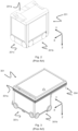
- shows a sensor module comprising a plurality of sensors.
- Fig. 5
- shows a sensor module mounted in a corner at an underside of a remotely operated vehicle in relation to rails in x and y direction.
- Fig. 6
- shows a sensor module mounted in a corner at an underside of a remotely operated vehicle.
- Fig. 7
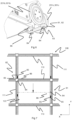
- shows a rail system with rails in x and y direction and with the position of the sensors in relation to the rails when the vehicle moves in the y-direction.
- Fig. 8
- shows a sensor module mounted in a corner at an underside of a remotely operated vehicle from yet another angle.
- Fig. 9
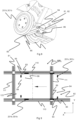
- shows a rail system with rails in x and y direction and with the position of the sensors in relation to the rails when the vehicle moves in the x-direction.
- Fig. 10
- shows the sensor module and the four sensors in a cross section from above in relation to the rails in x and y direction.
- Fig. 11
- shows a remotely operated vehicle comprising a first and a second sensor module arranged at a diametrically opposite a corner position of the vehicle.
- In the following, embodiments of the invention will be discussed in more detail with reference to the appended drawings. It should be understood, however, that the drawings are not intended to limit the invention to the subject-matter depicted in the drawings.
- Furthermore, even if some of the features of the present invention are described in relation to a rails system of a storage and
retrieval system 1 with aframework structure 100 in combination with container handling vehicles 201,301 suitable for operating on such system, it is apparent that the features of the present invention are valid for other rail systems (such as delivery rail system) and vehicles (such as delivery vehicles) and vice versa. - With reference to
Fig. 1 thestorage grid 104 of eachstorage structure 1 constitutes aframework 100 of in total 143grid columns 112, where the width and length of the framework corresponds to the width and length of 13 and 11grid columns 112, respectively. The top layer of theframework 100 is arail system 108 onto which a plurality of container handling vehicles 200,300 are operated. - The
framework 100 of thestorage system 1 is constructed in accordance with the above mentionedprior art framework 100 described above, i.e. a plurality ofupright members 102 and a plurality ofhorizontal members 103 which are supported by theupright members 102, and further that thehorizontal members 103 includes therail system 108 of parallel rails 110,111 in the X direction and the Y direction, respectively, arranged across the top ofstorage columns 105. The horizontal area of asingle grid cell 122, i.e. along the X and Y directions, may be defined by the distance betweenadjacent rails - The
rail system 108 allows thecontainer handling vehicles grid cell 122. - In
Fig. 1 , thestorage grid 104 is shown with a height of eight cells. It is understood, however, that thestorage grid 104 can in principle be of any size. In particular it is understood thatstorage grid 104 can be considerably wider and/or longer than disclosed inFigs. 1 . - The storage container vehicles 201,301 may be of any type known in the art, e.g. any one of the automated container handling vehicles disclosed in
WO2014/090684 A1 , in NO317366 or inWO2015/193278A1 . - The
rail system 108 may comprise a single track system. Alternatively, therail system 108 may be a double track system. Therail system 108 may also be a combination of single and double tracks. -
Figure 4 shows an arrangement of sensors for pre-alert and tracking of a position of ta remotely operated vehicle (not shown) following a travelling route relative to tracks laid out on rails in x-, y-directions on a rail system (not shown). - The arrangement comprises a
first sensor 83 directed to the rails in thex-direction 110, asecond sensor 84 directed to the rails in the y-direction 111, and athird sensor 85 directed to a corner of an intersection between the rails in the x-direction and y-direction 110,111. - The arrangement may also comprise a fourth sensor arranged to pre-alert a remaining distance to the arrival of the vehicle 201,301 at the position, by detecting any of the rails in the x-or y-direction 110,111.
- In
figure 4, 5 ,6 ,8 ,10 and 11 the beam of thesensors - Each of the
sensors - The sensors may be arranged on a sensor module as shown in
figure 4 . - The module may be mounted into the structure of the vehicle 201,301 and at least partly behind the wheels of the vehicle as shown in
figure 5 . - The arrangement of the present invention may comprise a first or a
second sensor module sensor module more sensors fig. 11 ). - The first and
second sensor module sensor module rail system 108. The travelling direction of the vehicle 201,301 may define which is the first andsecond sensor module - The
sensor module first sensor 83 is directed to the rails in thex-direction 110, asecond sensor 84 is directed to the rails in the y-direction 111, the first andsecond sensors third sensor 85 directed to a corner of an intersection between the rail structure in thex-direction 110 and y-direction 111. - The
sensor module forth sensor 86 configured to pre-alert a remaining distance to the arrival of the vehicle at the position, by detecting the rail structure in the x-or y-direction 110,111. -
Figures 4,5 ,6 ,8 ,10 and 11 shows thesensor module sensors sensor module - The first and
second sensor module wheels sensors second sensor module -
Figure 7 shows arail system 108 from above and thesensors rail system 108. The vehicle (not shown) comprises afirst sensor system 81 located in a front corner in the moving direction of the vehicle 201,301, and asecond sensor module 82 located in a diametrically opposite corner position at the back of the moving direction of the vehicle 201,301. - Each
sensor module first sensor 83 directed to the rail in thex-direction 110, asecond sensor 84 directed to the rail in the y-direction 111, athird sensor 85 directed to a corner of an intersection between the rail structure in the x-direction and y-direction 110,111, and aforth sensor 86 located at a predefined location and configured to pre-alert a remaining distance to the arrival of the vehicle 201,301 at the position, by detecting the rail structure in the x or y direction 110,111. The "remaining distance" may vary according to the location of thefourth sensor 86 relative to the vehicle 201,301. The first 83 and second 84 sensors are spaced from the corner position so that they may detect the rail in the x- and y-direction simultaneously while located at the set position, such that the set position can be confirmed with reference to the rails in x-and y-direction 110,111. - While the vehicle 201,301 is moving in the y-direction of the rail system towards a set location on a
grid cell 122, thesecond sensor 84 detects the rails in the y-direction 111 continuously (the sensor is following the rails in y-direction). Thefourth sensor 86 of thesecond sensor module 82 is located at a location relative to the vehicle, such that when thesensor 86 detects the rail structure in thex-direction 110 of thegrid cell 122 of the set position, it sends a signal to a controller so as to pre-alert the remaining distance to the set position. Thus, the remaining distance to the set position is defined by the position of thefourth sensor 86 relative to the vehicle 201,301. As shown infigure 7 , the remaining distance may be set to about 10 cm. If a longer "remaining distance" is preferred, thefourth sensor 86 may be moved closer towards the center of the vehicle, such that the remaining distance can be increased accordingly. The fourth sensor may be integrated into thesensor modules - Furthermore, when the vehicle 201,301 arrives at a set position located on a
grid cell 122 of therail system 108, thefirst sensor 83 of the first andsecond sensor x-direction 110, thesecond sensor 84 of the first andsecond sensor direction 111, thethird sensor 85 the first andsecond sensor third sensor 85 should detect an obstacle (i.e. a rail structure), then the controller would know that the vehicle 201,301 is located in an offset position (hence, not correctly at the set position on the grid cell). While at the set position on agrid cell 122, the first, second andthird sensors - The first and
second sensor system rail system 108. Thefirst sensor module 81 may be defined as the front sensor module of the vehicle, in the moving direction of the vehicle 201,301. Such that when the vehicle 201,301 moves in opposite direction, the previoussecond sensor module 82 becomes thefirst sensor module 81. - The
figure 9 shows thesensors second sensor module rail system 108. Accordingly, thefirst sensor module 83 is located in the front corner of the vehicle 201,301, and thesecond sensor module 82 is located in a diametrically opposite corner position at the back of the vehicle 201,301 (seen in the moving direction of the vehicle). - Each
sensor module first sensor 83 directed to the rail in thex-direction 110, asecond sensor 84 directed to the rail in the y-direction 111, athird sensor 85 directed to a corner of an intersection between the rail structure in the x-direction and y-direction 110,111, and aforth sensor 86 configured to pre-alert a remaining distance to the arrival of the vehicle at the position, by detecting the rail structure in the x or y direction 110,111. The first 83 and second 84 sensor are spaced from the corner position so that they may detect the rails in respective the x- and y-direction 110,111. Each of the first and second sensor module 81.82 may be equally spaced from the corner position on the vehicle 201,301. - While moving in the x-direction of the
rail system 110 towards a set location on agrid cell 122, thefirst sensor 83 detects the rails in the x-direction 110 continuously as the vehicle 201,301 moves along rails in the x-direction. Thefourth sensor 86 of thesecond sensor module 82 is located such that when thesensor 86 detects the rail structure in the y-direction 111 of thegrid cell 122 of the set position, it sends a signal to a controller so as to pre-alert the remaining distance to the set position. Thus, the remaining distance to the set position is defined by the position of thefourth sensor 86 relative to the vehicle 201,301. As shown infigure 9 , the remaining distance may be set to about 10 cm. Any pre-preferable distance may be obtained by moving the location of thefourth sensor 86, relative to the vehicle. - Furthermore, when the vehicle 201,301 arrives at a set position located on a
grid cell 122 of therails system 108, thefirst sensor 83 of the first andsecond sensor module x-direction 110, thesecond sensor 84 of the first andsecond sensor direction 111, thethird sensor 85 of the first andsecond sensor third sensor 85 should detect an obstacle (i.e. a rail structure), then the controller would know that the vehicle 201,301 is located in an offset position (hence, not correctly at the set position on the grid cell). The first, second andthird sensors - Accordingly,
sensors second sensor system rail system 108. Thefirst sensor module 81 may be defined as the front sensor module in the moving direction of the vehicle 201,301. Such that when the vehicle 201,301 moves in opposite direction, the previoussecond sensor module 82 becomes thefirst sensor module 81. -
Figure 10 shows a cross section of the remotely operated vehicle 201,301 taken horizontally through the first orsecond sensor module sensor module first sensor 83 is detecting the rail in thex-direction 110, and thesecond sensor 84 is detecting the rail in the y-direction 111. The third sensor is situated at the corner of the intersection between the x-rail 110 and y-rail 111 and detects no obstacles. -
Figure 11 shows thefirst sensor module 81 and thesecond sensor module 82 dependent of the direction of travel for the vehicle 201,301. Thesensor modules sensor modules first sensor module 81, depending on the moving direction of the vehicle 201,301. -
- P1
- Horizontal plane of delivery rail grid
- 100
- Framework structure
- 102
- Upright members of framework structure
- 103
- Horizontal members of framework structure
- 104
- Storage grid / three-dimensional grid
- 105
- Storage column
- 106
- Storage container
- 107
- Stack
- 108
- Rail system
- 110
- First set of parallel rails in first direction (X)
- 111
- Second set of parallel rails in second direction (Y)
- 119
- Delivery column
- 120
- Delivery column
- 122
- Grid cell
- 201
- First container handling vehicle
- 201 b,c
- Wheel arrangement in x-y-directions of first container handling vehicle
- 301
- Second container handling vehicle
- 301b,c
- Wheel arrangement in x-y-directions of second container handling vehicle
- X
- First direction
- Y
- Second direction
- P
- Horizontal plane of rail system
- 81
- First sensor module
- 82
- Second sensor module
- 83
- First sensor
- 84
- Second sensor
- 85
- Third sensor
- 86
- Fourth sensor
- Also disclosed herein are the following numbered clauses:
- 1. A remotely operated vehicle (201,301) comprising an arrangement to provide a pre-alert and tracking of a position of the vehicle following a travelling route relative to tracks laid out on rails in x-, y-directions (110,111) on a rail system (108), the vehicle (201,301) having first and seconds sets of wheels (201b,301b,201c,301c) connected to drives for moving the vehicle (201,301) in corresponding x-, y-directions on the rail system (108),
- wherein the arrangement comprises at least three sensors:
- a first sensor (83) directed to the rails in the x-direction (110),
- a second sensor (84) directed to the rails in the y-direction (111), and
- a third sensor (85) directed to a corner of an intersection between the rails in the x-direction and y-direction (110,111),
- wherein each of the sensors (83,84,85) are directed downwardly towards the rails in x-, y-directions (110,111) for determining the position of the vehicle (201,301) relative to the rails (110,111).
- wherein the arrangement comprises at least three sensors:
- 2. The remotely operated vehicle according to
clause 1, wherein the first sensor (83), the second sensor (84) and the third sensor (85) are arranged in a sensor module (81,82). - 3. The remotely operated vehicle according to clause 2, wherein the sensor module (81,82) is mounted into the structure of the vehicle (201,301) in a corner position at least partly behind the wheels (201b,301b,201c,301c) of the vehicle (201,301).
- 4. The remotely operated vehicle according to any one of clauses 2 or 3, wherein the arrangement comprises two sensor modules; a first sensor module (81) arranged in the corner position of the vehicle, and a second sensor module (82) arranged at a diametrically opposite a corner position of the vehicle (201,301) such that the corresponding sensors (83,84,85) of the first and second sensor module (81,82) are equally spaced from their corner position.
- 5. The remotely operated vehicle according to any one of clauses 1-4, wherein the arrangement comprises a forth sensor (86) configured to pre-alert a remaining distance to the arrival of the vehicle (201,301) at the position, by detecting any of the rails in the x-or y-direction (110,111).
- 6. The remotely operated vehicle according to clause 5, wherein the fourth sensor (86) is arranged in the sensor module (81,82) together with the first, second and third sensors (83,84,85).
- 7. The remotely operated vehicle according to any one of the preceding clauses, wherein output of the sensors (83,84,85,86) are used in a feedback loop in a controller for providing signals causing additional or less deceleration of the vehicle (201,301).
- 8. A method for pre-alerting and tracking of a position of a remotely operated vehicle (201,301) following a travelling route relative to tracks laid out on rails in x, y directions (110,111) on a rail system (108), the vehicle (201,301) having first and seconds sets of wheels (201b,301b,201c,301c) connected to drives for moving the vehicle (201,301) in corresponding x-, y-directions on the rail system (108),
- wherein the vehicle comprises an arrangement comprising at least three sensors:
- a first sensor (83) directed to the rails in the x-direction (110),
- a second sensor (84) directed to the rails in the y-direction (111), and
- a third sensor (85) directed to a corner of an intersection between the rails in the x-direction and y-direction (110,111),
- wherein the method comprises the step of:
- moving the vehicle (201,301) on rails in the x- and y-directions (110,111) according to the travelling route towards the position;
- receiving output from the sensors (83,84,85) when it detects a rail in the x-or y-directions (110,111) of the rails defining the grid cell of the position;
- using the output in a feedback loop to a controller;
- providing signals to the wheels (201b,301b,201c,301c) for additional or less deceleration as necessary based on a predetermined or model of the change of speed profile stored in the controller's memory,
- detecting, controlling and confirming the position of the vehicle (201,301) based on measured data from a first, second and third sensor (83,84,85).
- wherein the vehicle comprises an arrangement comprising at least three sensors:
- 9. The method according to clause 8, wherein the arrangement comprises a forth sensor (86) configured to pre-alert a remaining distance to the arrival of the vehicle (201,301) at the set position, by detecting the rail structure in any of the x-or y-direction (110,111).
- 10. The method according to clause 9, wherein the first, second, third and fourth sensors (83,84,85,86) are arranged in a sensor module (81,82).
- 11. The method according to clause 10, wherein the arrangement comprises two sensor modules; a first sensor module (81) arranged in the corner position of the vehicle, and a second sensor module (82) arranged at a diametrically opposite a corner position of the vehicle (201,301) such that the corresponding sensors (83,84,85,86) of the first and second sensor module (81,82) are equally spaced from their corner position.
Claims (8)
- A remotely operated vehicle (201,301) comprising a sensor module for providing a pre-alert and tracking of a position of the vehicle following a route relative to tracks laid out on rails in x-, y-directions (110,111) on a rail system (108), the vehicle (201,301) having first and seconds sets of wheels (201b,301b,201c,301c) connected to drives for moving the vehicle (201,301) in corresponding x-, y-directions on the rail system (108),wherein the sensor module comprises:- a first sensor (83) directed downwards to detect the rails in the x-direction (110),- a second sensor (84) directed downwards to detect the rails in the y-direction (111), and- a third sensor (85) directed downwards to detect a corner of an intersection between the rails in the x-direction and y-direction (110,111),wherein each of the sensors (83,84,85) are directed downwardly towards the rails in x-, y-directions (110,111) for determining the position of the vehicle (201,301) relative to the rails (110,111), and wherein the sensor module is mounted in a corner position in a structure of the vehicle, at least partly behind the wheels of the vehicle.
- The remotely operated vehicle according to claim 1 , wherein the sensor module (81,82) is mounted into the structure of the vehicle (201,301) in a corner position at least partly behind the wheels (201b,301b,201c,301c) of the vehicle (201,301).
- The remotely operated vehicle according to claim 1 or claim 2, wherein the arrangement comprises two sensor modules; a first sensor module (81) arranged in the corner position of the vehicle, and a second sensor module (82) arranged at a diametrically opposite corner position of the vehicle (201,301) such that the corresponding sensors (83,84,85) of the first and second sensor module (81,82) are equally spaced from their respective corner positions.
- The remotely operated vehicle according to any one of claims 1-3, wherein the sensor module comprises a fourth sensor (86) configured to pre-alert a remaining distance to the arrival of the vehicle (201,301) at a set position, by detecting any of the rails in the x- or y-direction (110, 111), wherein the fourth sensor (86) is arranged in the sensor module (81,82) together with the first, second and third sensors (83,84,85).
- The remotely operated vehicle according to any one of the preceding claims further comprising a controller, wherein the controller is configured to employ the output of the sensors (83,84,85,86) in a feedback loop for providing signals to cause additional or less deceleration of the vehicle (201,301).
- A method for pre-alerting and tracking of a position of a remotely operated vehicle (201,301) following a travelling route relative to tracks laid out on rails in x, y directions (110,111) on a rail system (108), the vehicle (201,301) having first and seconds sets of wheels (201b,301b,201c,301c) connected to drives for moving the vehicle (201,301) in corresponding x-, y-directions on the rail system (108),
wherein the vehicle comprises an arrangement of a controller and a sensor module, the sensor module mounted in a corner position in a structure of the vehicle, at least partly behind the wheels of the vehicle, the sensor module comprising:- a first sensor (83) directed downwards to detect the rails in the x-direction (110),- a second sensor (84) directed downwards to detect the rails in the y-direction (111), and- a third sensor (85) directed downwards to detect a corner of an intersection between the rails in the x-direction and y-direction (110,111),and wherein the method comprises the step of:- moving the vehicle (201,301) on rails in the x- and y-directions (110,111) according to the travelling route towards the position,- receiving output from the sensors (83,84,85) it detects a rail in the x-or y-directions (110,111) of the rails defining a grid cell of the position,- using the output in a feedback loop to a controller,- providing signals to the wheels (201b,301b,201c,301c) for additional or less deceleration as necessary based on a predetermined or model of the change of speed profile stored in the controller's memory,- detecting, controlling and confirming the position of the vehicle (201,301) based on measured data from the first, second, third and fourth sensor (83,84,85,86). - The method according to claim 6, wherein the sensor module comprises a fourth sensor (86) configured to pre-alert a remaining distance to the arrival of the vehicle (201, 301) at the set position, by detecting the rail structure in any of the x- or y- direction (110,111), wherein the first, second, third and fourth sensors (83,84,85,86) are arranged in the sensor module (81,82).
- The method according to claim 7, wherein the arrangement comprises two sensor modules; a first sensor module (81) arranged in the corner position of the vehicle, and a second sensor module (82) arranged at a diametrically opposite corner position of the vehicle (201,301) such that the corresponding sensors (83,84,85,86) of the first and second sensor module (81,82) are equally spaced from their respective corner positions.
Applications Claiming Priority (3)
| Application Number | Priority Date | Filing Date | Title |
|---|---|---|---|
| NO20191506A NO346390B1 (en) | 2019-12-20 | 2019-12-20 | Track sensor arrangement for a remotely operated vehicle and a method thereof |
| EP20841667.7A EP4078317B1 (en) | 2019-12-20 | 2020-12-15 | A remotely operated vehicle with an arrangement to provide a pre-alert and tracking of a position of the vehicle |
| PCT/EP2020/086254 WO2021122619A1 (en) | 2019-12-20 | 2020-12-15 | A remotely operated vehicle with an arrangement to provide a pre-alert and tracking of a position of the vehicle |
Related Parent Applications (1)
| Application Number | Title | Priority Date | Filing Date |
|---|---|---|---|
| EP20841667.7A Division EP4078317B1 (en) | 2019-12-20 | 2020-12-15 | A remotely operated vehicle with an arrangement to provide a pre-alert and tracking of a position of the vehicle |
Publications (2)
| Publication Number | Publication Date |
|---|---|
| EP4527760A2 true EP4527760A2 (en) | 2025-03-26 |
| EP4527760A3 EP4527760A3 (en) | 2025-04-16 |
Family
ID=74183096
Family Applications (2)
| Application Number | Title | Priority Date | Filing Date |
|---|---|---|---|
| EP20841667.7A Active EP4078317B1 (en) | 2019-12-20 | 2020-12-15 | A remotely operated vehicle with an arrangement to provide a pre-alert and tracking of a position of the vehicle |
| EP25156493.6A Pending EP4527760A3 (en) | 2019-12-20 | 2020-12-15 | A remotely operated vehicle with an arrangement to provide a pre-alert and tracking of a position of the vehicle |
Family Applications Before (1)
| Application Number | Title | Priority Date | Filing Date |
|---|---|---|---|
| EP20841667.7A Active EP4078317B1 (en) | 2019-12-20 | 2020-12-15 | A remotely operated vehicle with an arrangement to provide a pre-alert and tracking of a position of the vehicle |
Country Status (10)
| Country | Link |
|---|---|
| US (2) | US12434909B2 (en) |
| EP (2) | EP4078317B1 (en) |
| JP (1) | JP7624004B2 (en) |
| KR (1) | KR102949259B1 (en) |
| CN (1) | CN114846426A (en) |
| CA (1) | CA3161160A1 (en) |
| ES (1) | ES3032396T3 (en) |
| NO (1) | NO346390B1 (en) |
| PL (1) | PL4078317T3 (en) |
| WO (1) | WO2021122619A1 (en) |
Families Citing this family (6)
| Publication number | Priority date | Publication date | Assignee | Title |
|---|---|---|---|---|
| KR20240158947A (en) * | 2022-03-08 | 2024-11-05 | 오토스토어 테크놀로지 에이에스 | Track sensor device |
| CN115268347B (en) * | 2022-09-28 | 2023-01-06 | 山西航天清华装备有限责任公司 | Remote control transfer trolley and control system and method thereof |
| JP7426748B1 (en) | 2022-10-21 | 2024-02-02 | 建ロボテック株式会社 | Travel control method and travel control system for self-propelled work robot |
| CN117302829B (en) * | 2023-11-30 | 2024-03-22 | 无锡西爵信息科技有限公司 | Automatic medical instrument storage control system and control method |
| SE2351398A1 (en) * | 2023-12-06 | 2025-02-18 | Flexlink Ab | Track tile module, modular track system, and method for manufacturing a track tile module |
| EP4685083A1 (en) * | 2024-07-24 | 2026-01-28 | AutoStore Technology AS | Mount |
Citations (5)
| Publication number | Priority date | Publication date | Assignee | Title |
|---|---|---|---|---|
| WO2014075937A1 (en) | 2012-11-13 | 2014-05-22 | Jakob Hatteland Logistics As | Storage system |
| WO2014090684A1 (en) | 2012-12-10 | 2014-06-19 | Jakob Hatteland Logistics As | Robot for transporting storage bins |
| WO2015193278A1 (en) | 2014-06-19 | 2015-12-23 | Jakob Hatteland Logistics As | Robot for transporting storage bins |
| WO2018082972A1 (en) | 2016-11-02 | 2018-05-11 | Autostore Technology AS | Track sensors for detecting position of vehicle relative to tracks |
| WO2018146304A1 (en) | 2017-02-13 | 2018-08-16 | Autostore Technology AS | Rail arrangement for a storage system |
Family Cites Families (9)
| Publication number | Priority date | Publication date | Assignee | Title |
|---|---|---|---|---|
| NO317366B1 (en) | 1999-07-01 | 2004-10-18 | Autostore As | Storage system with remote controlled wagons with two wheelsets and lifting device for operation on rails arranged in cross over columns of storage units separated by vertical profile posts |
| US6550666B2 (en) | 2001-08-21 | 2003-04-22 | Advanpack Solutions Pte Ltd | Method for forming a flip chip on leadframe semiconductor package |
| DE102015001410A1 (en) * | 2015-02-06 | 2016-08-11 | Gebhardt Fördertechnik GmbH | Pallet transport device |
| NO340577B1 (en) * | 2015-09-04 | 2017-05-15 | Jakob Hatteland Logistics As | Method for fetching a target bin stored in a storage system and a storage system which includes a control device operating in accordance with the method |
| WO2019094511A1 (en) * | 2017-11-07 | 2019-05-16 | Nordstrom, Inc. | Systems and methods for storage, retrieval, and sortation in supply chain |
| NO346364B1 (en) * | 2018-04-25 | 2022-06-27 | Autostore Tech As | Container handling vehicle with first and second sections and battery in second section, and system. |
| GB201803771D0 (en) * | 2018-03-09 | 2018-04-25 | Ocado Innovation Ltd | Transporting device position determining apparatus and method |
| JP7300468B2 (en) * | 2018-06-08 | 2023-06-29 | アタボティックス インコーポレイテッド | A storage and retrieval system that shares a common robotic fleet between storage grids and external work stations |
| DE102019214608A1 (en) | 2019-09-24 | 2021-03-25 | Gebhardt Fördertechnik GmbH | Transport vehicle and a storage and removal system for containers |
-
2019
- 2019-12-20 NO NO20191506A patent/NO346390B1/en unknown
-
2020
- 2020-12-15 WO PCT/EP2020/086254 patent/WO2021122619A1/en not_active Ceased
- 2020-12-15 EP EP20841667.7A patent/EP4078317B1/en active Active
- 2020-12-15 PL PL20841667.7T patent/PL4078317T3/en unknown
- 2020-12-15 CN CN202080088967.3A patent/CN114846426A/en active Pending
- 2020-12-15 KR KR1020227024496A patent/KR102949259B1/en active Active
- 2020-12-15 JP JP2022537487A patent/JP7624004B2/en active Active
- 2020-12-15 CA CA3161160A patent/CA3161160A1/en active Pending
- 2020-12-15 US US17/757,412 patent/US12434909B2/en active Active
- 2020-12-15 ES ES20841667T patent/ES3032396T3/en active Active
- 2020-12-15 EP EP25156493.6A patent/EP4527760A3/en active Pending
-
2025
- 2025-05-29 US US19/222,126 patent/US20250289659A1/en active Pending
Patent Citations (5)
| Publication number | Priority date | Publication date | Assignee | Title |
|---|---|---|---|---|
| WO2014075937A1 (en) | 2012-11-13 | 2014-05-22 | Jakob Hatteland Logistics As | Storage system |
| WO2014090684A1 (en) | 2012-12-10 | 2014-06-19 | Jakob Hatteland Logistics As | Robot for transporting storage bins |
| WO2015193278A1 (en) | 2014-06-19 | 2015-12-23 | Jakob Hatteland Logistics As | Robot for transporting storage bins |
| WO2018082972A1 (en) | 2016-11-02 | 2018-05-11 | Autostore Technology AS | Track sensors for detecting position of vehicle relative to tracks |
| WO2018146304A1 (en) | 2017-02-13 | 2018-08-16 | Autostore Technology AS | Rail arrangement for a storage system |
Also Published As
| Publication number | Publication date |
|---|---|
| EP4078317B1 (en) | 2025-03-12 |
| US20250289659A1 (en) | 2025-09-18 |
| ES3032396T3 (en) | 2025-07-18 |
| US12434909B2 (en) | 2025-10-07 |
| JP7624004B2 (en) | 2025-01-29 |
| KR102949259B1 (en) | 2026-04-08 |
| CA3161160A1 (en) | 2021-06-24 |
| US20230024692A1 (en) | 2023-01-26 |
| PL4078317T3 (en) | 2025-07-07 |
| WO2021122619A1 (en) | 2021-06-24 |
| EP4078317C0 (en) | 2025-03-12 |
| NO346390B1 (en) | 2022-07-04 |
| EP4527760A3 (en) | 2025-04-16 |
| EP4078317A1 (en) | 2022-10-26 |
| KR20220118488A (en) | 2022-08-25 |
| NO20191506A1 (en) | 2021-06-21 |
| JP2023508904A (en) | 2023-03-06 |
| CN114846426A (en) | 2022-08-02 |
Similar Documents
| Publication | Publication Date | Title |
|---|---|---|
| EP4078317B1 (en) | A remotely operated vehicle with an arrangement to provide a pre-alert and tracking of a position of the vehicle | |
| JP7357647B2 (en) | How to operate an automatic storage and retrieval system | |
| TWI619660B (en) | Storage and retrieval system with automatic transportation machine position sensing and operation method thereof | |
| EP0035890A1 (en) | A system and method for controlling the relative positioning of two objects such as an article handling vehicle and a storage location | |
| US20240217740A1 (en) | Container handler and method for handling a storage container | |
| US20250171240A1 (en) | Track sensor arrangement | |
| CA3039836A1 (en) | Track sensors for detecting position of vehicle relative to tracks | |
| EP4545451A2 (en) | Section based speed reduction | |
| US20240417168A1 (en) | System and method for using a camera to detect robot position on grid | |
| NO346982B1 (en) | System, method and computer program product of determining a position of a container handling vehicle in an automated grid based storage and retrieval system | |
| HK40077781A (en) | A remotely operated vehicle with an arrangement to provide a pre-alert and tracking of a position of the vehicle | |
| US20230384796A1 (en) | Method, system and computer program product for controlling movement of a plurality of container handling vehicles | |
| NO348629B1 (en) | Track sensor arrangement | |
| CN118811327A (en) | A method for controlling the entry and exit of a bridge-type crane intelligent stereoscopic warehouse | |
| CN118765252A (en) | Guide rail sensor structure | |
| NO347574B1 (en) | A device and a method for determining rotational position of a rotating shaft | |
| CN121361639A (en) | Transfer robot, pick-and-place positioning method thereof, warehouse system and storage medium |
Legal Events
| Date | Code | Title | Description |
|---|---|---|---|
| PUAI | Public reference made under article 153(3) epc to a published international application that has entered the european phase |
Free format text: ORIGINAL CODE: 0009012 |
|
| STAA | Information on the status of an ep patent application or granted ep patent |
Free format text: STATUS: THE APPLICATION HAS BEEN PUBLISHED |
|
| PUAL | Search report despatched |
Free format text: ORIGINAL CODE: 0009013 |
|
| AC | Divisional application: reference to earlier application |
Ref document number: 4078317 Country of ref document: EP Kind code of ref document: P |
|
| AK | Designated contracting states |
Kind code of ref document: A2 Designated state(s): AL AT BE BG CH CY CZ DE DK EE ES FI FR GB GR HR HU IE IS IT LI LT LU LV MC MK MT NL NO PL PT RO RS SE SI SK SM TR |
|
| AK | Designated contracting states |
Kind code of ref document: A3 Designated state(s): AL AT BE BG CH CY CZ DE DK EE ES FI FR GB GR HR HU IE IS IT LI LT LU LV MC MK MT NL NO PL PT RO RS SE SI SK SM TR |
|
| RIC1 | Information provided on ipc code assigned before grant |
Ipc: G05D 111/10 20240101ALN20250310BHEP Ipc: G05D 109/10 20240101ALN20250310BHEP Ipc: G05D 107/70 20240101ALN20250310BHEP Ipc: G05D 105/28 20240101ALN20250310BHEP Ipc: G05D 1/243 20240101ALI20250310BHEP Ipc: G05D 1/225 20240101ALI20250310BHEP Ipc: B65G 1/00 20060101ALI20250310BHEP Ipc: B65G 1/04 20060101AFI20250310BHEP |
|
| STAA | Information on the status of an ep patent application or granted ep patent |
Free format text: STATUS: REQUEST FOR EXAMINATION WAS MADE |
|
| 17P | Request for examination filed |
Effective date: 20250905 |
|
| STAA | Information on the status of an ep patent application or granted ep patent |
Free format text: STATUS: EXAMINATION IS IN PROGRESS |
|
| 17Q | First examination report despatched |
Effective date: 20251110 |
|
| RAP3 | Party data changed (applicant data changed or rights of an application transferred) |
Owner name: AUTOSTORE TECHNOLOGY AS |