EP4527749A1 - Forming unit for forming a tube from a web of packaging material, an apparatus for producing a sealed tube provided with said forming unit, a packaging machine with said apparatus and a method to operate said apparatus - Google Patents
Forming unit for forming a tube from a web of packaging material, an apparatus for producing a sealed tube provided with said forming unit, a packaging machine with said apparatus and a method to operate said apparatus Download PDFInfo
- Publication number
- EP4527749A1 EP4527749A1 EP24190462.2A EP24190462A EP4527749A1 EP 4527749 A1 EP4527749 A1 EP 4527749A1 EP 24190462 A EP24190462 A EP 24190462A EP 4527749 A1 EP4527749 A1 EP 4527749A1
- Authority
- EP
- European Patent Office
- Prior art keywords
- packaging material
- web
- lateral portion
- forming
- forming unit
- Prior art date
- Legal status (The legal status is an assumption and is not a legal conclusion. Google has not performed a legal analysis and makes no representation as to the accuracy of the status listed.)
- Pending
Links
Images


Classifications
-
- B—PERFORMING OPERATIONS; TRANSPORTING
- B65—CONVEYING; PACKING; STORING; HANDLING THIN OR FILAMENTARY MATERIAL
- B65B—MACHINES, APPARATUS OR DEVICES FOR, OR METHODS OF, PACKAGING ARTICLES OR MATERIALS; UNPACKING
- B65B9/00—Enclosing successive articles, or quantities of material, e.g. liquids or semiliquids, in flat, folded, or tubular webs of flexible sheet material; Subdividing filled flexible tubes to form packages
- B65B9/10—Enclosing successive articles, or quantities of material, in preformed tubular webs, or in webs formed into tubes around filling nozzles, e.g. extruded tubular webs
- B65B9/20—Enclosing successive articles, or quantities of material, in preformed tubular webs, or in webs formed into tubes around filling nozzles, e.g. extruded tubular webs the webs being formed into tubes in situ around the filling nozzles
- B65B9/2014—Tube advancing means
- B65B9/2028—Rollers or belts
-
- B—PERFORMING OPERATIONS; TRANSPORTING
- B65—CONVEYING; PACKING; STORING; HANDLING THIN OR FILAMENTARY MATERIAL
- B65B—MACHINES, APPARATUS OR DEVICES FOR, OR METHODS OF, PACKAGING ARTICLES OR MATERIALS; UNPACKING
- B65B51/00—Devices for, or methods of, sealing or securing package folds or closures; Devices for gathering or twisting wrappers, or necks of bags
- B65B51/10—Applying or generating heat or pressure or combinations thereof
- B65B51/26—Devices specially adapted for producing transverse or longitudinal seams in webs or tubes
-
- B—PERFORMING OPERATIONS; TRANSPORTING
- B65—CONVEYING; PACKING; STORING; HANDLING THIN OR FILAMENTARY MATERIAL
- B65B—MACHINES, APPARATUS OR DEVICES FOR, OR METHODS OF, PACKAGING ARTICLES OR MATERIALS; UNPACKING
- B65B55/00—Preserving, protecting or purifying packages or package contents in association with packaging
- B65B55/02—Sterilising, e.g. of complete packages
- B65B55/04—Sterilising wrappers or receptacles prior to, or during, packaging
- B65B55/10—Sterilising wrappers or receptacles prior to, or during, packaging by liquids or gases
- B65B55/103—Sterilising flat or tubular webs
-
- B—PERFORMING OPERATIONS; TRANSPORTING
- B65—CONVEYING; PACKING; STORING; HANDLING THIN OR FILAMENTARY MATERIAL
- B65B—MACHINES, APPARATUS OR DEVICES FOR, OR METHODS OF, PACKAGING ARTICLES OR MATERIALS; UNPACKING
- B65B9/00—Enclosing successive articles, or quantities of material, e.g. liquids or semiliquids, in flat, folded, or tubular webs of flexible sheet material; Subdividing filled flexible tubes to form packages
- B65B9/10—Enclosing successive articles, or quantities of material, in preformed tubular webs, or in webs formed into tubes around filling nozzles, e.g. extruded tubular webs
- B65B9/20—Enclosing successive articles, or quantities of material, in preformed tubular webs, or in webs formed into tubes around filling nozzles, e.g. extruded tubular webs the webs being formed into tubes in situ around the filling nozzles
- B65B9/22—Forming shoulders; Tube formers
-
- B—PERFORMING OPERATIONS; TRANSPORTING
- B65—CONVEYING; PACKING; STORING; HANDLING THIN OR FILAMENTARY MATERIAL
- B65B—MACHINES, APPARATUS OR DEVICES FOR, OR METHODS OF, PACKAGING ARTICLES OR MATERIALS; UNPACKING
- B65B51/00—Devices for, or methods of, sealing or securing package folds or closures; Devices for gathering or twisting wrappers, or necks of bags
- B65B51/10—Applying or generating heat or pressure or combinations thereof
- B65B51/20—Applying or generating heat or pressure or combinations thereof by fluid pressure acting directly on folds or on opposed surfaces, e.g. using hot-air jets
-
- B—PERFORMING OPERATIONS; TRANSPORTING
- B65—CONVEYING; PACKING; STORING; HANDLING THIN OR FILAMENTARY MATERIAL
- B65B—MACHINES, APPARATUS OR DEVICES FOR, OR METHODS OF, PACKAGING ARTICLES OR MATERIALS; UNPACKING
- B65B51/00—Devices for, or methods of, sealing or securing package folds or closures; Devices for gathering or twisting wrappers, or necks of bags
- B65B51/10—Applying or generating heat or pressure or combinations thereof
- B65B51/22—Applying or generating heat or pressure or combinations thereof by friction or ultrasonic or high-frequency electrical means
- B65B51/227—Applying or generating heat or pressure or combinations thereof by friction or ultrasonic or high-frequency electrical means by induction welding
Definitions
- the present invention relates to a forming unit for forming a tube from a web of packaging material, an apparatus for producing a sealed tube provided with said forming unit, a packaging machine with said apparatus and a method to operate said apparatus.
- liquid or pourable food products such as for example pasteurized or long-life (UHT) milk, tomato sauce, wine, fruit juice are sold in packages made of sterilized packaging material.
- UHT pasteurized or long-life
- Packages of this sort are normally produced with automatic packaging machines, which feed a web of packaging material through a sterilizing unit by means of known guiding elements (like for example rollers) for sterilizing the web of packaging material alternatively by means of chemical sterilization in a sterilizing bath (e.g. by applying a chemical sterilizing agent, such as a hydrogen peroxide solution) or by means of physical sterilization (e.g. by means of an electron beam).
- a sterilizing bath e.g. by applying a chemical sterilizing agent, such as a hydrogen peroxide solution
- physical sterilization e.g. by means of an electron beam
- the packaging machine further comprises a folding unit arranged downstream of the sterilizing unit, extending substantially vertically and designed to fold the web of packaging material for producing a continuous tube.
- a folding unit arranged downstream of the sterilizing unit, extending substantially vertically and designed to fold the web of packaging material for producing a continuous tube.
- the web of packaging material is folded from a continuous planar shape to a continuous tubular shape with a vertical axis.
- the web of packaging material with a planar shape is folded into a cylinder that is successively subdivided into a plurality of pillow packs which are subjected to successive mechanical folding operations to obtain the finished sealed packages.
- the folding unit is preferably arranged within a fixed structure in which the web of packaging material is maintained in a sterile-air environment.
- the folding unit further comprises a number of folding devices placed in succession (one after the other): by interacting with the folding devices, opposite lateral portions (or edges) of the web of packaging material are placed one on top of the one another so as to form the tube and so as to define an overlapping area.
- the packaging machine further comprises a sealing unit for sealing overlapping lateral portions of the web of packaging material to finally obtain a fluid-tight longitudinal seal in the tube.
- the sealing unit is arranged between two folding devices along the conveying path and comprises a heating device and a number of supporting devices, at least partially connected to the heating device, and realized to contact and maintain in a predetermined position at least part of the web of packaging material.
- the assembly made by the heating element and the supporting devices connected thereto is movable between an operating position wherein the heating element is interposed between the two overlapping lateral portions and a rest position wherein the assembly is at a distance from the web of packaging material.
- the assembly made by the heating element and the supporting devices is moved from the operating position to the rest position to avoid directing too much heat onto the web of packaging material.
- the known folding and sealing units operate satisfyingly well, a desire is felt for improving the known units, in particular the interruption of operation that are influenced by the movement of the heating element.
- the movement of the heating element between the operating position and the rest position may lead (after or during the movement) to arranging the heating element in a non-ideal position due to mechanical reasons or into contact with the web of packaging material.
- the object of the invention is to provide forming unit for forming a tube from a web of packaging material addressing the drawbacks described above and, in particular, being easy and economical to be manufactured.
- a further object of the invention is to provide an apparatus for producing a sealed tube addressing the drawbacks described above and, in particular, being easy and economical to be manufactured.
- a further object of the invention is to provide a packaging machine addressing the drawbacks described above and, in particular, being easy and economical to be manufactured.
- a further object of the invention is to provide a method to operate an apparatus for producing a sealed tube addressing the drawbacks described above and, in particular, being easy and economical to be implemented.
- a forming unit for forming a tube from a web of packaging material an apparatus for producing a sealed tube provided with said forming unit, a packaging machine with said apparatus and a method to operate said apparatus according to the appended claims.
- Figures 1 and 2 disclose, as a whole, a packaging machine 1 for continuously producing sealed packages, containing a pourable food product, such as for example pasteurized or long-life (UHT) milk, tomato sauce, wine, fruit juice.
- a pourable food product such as for example pasteurized or long-life (UHT) milk, tomato sauce, wine, fruit juice.
- UHT pasteurized or long-life
- the sealed packages are obtained from a packaging material unwound from a reel 3 and fed along a conveying path P.
- the packaging material has the shape of a continuous planar web 4 of packaging material.
- the packaging material has a multi-layer structure. More specifically, the packaging material may comprise at least a layer of fibrous material, such as for example a paper or cardboard layer, and at least two layers of heat-seal plastic material, e.g. polyethylene, with the layer of fibrous material interposed between them. One of these two layers of heat-seal plastic material may define the inner face of the packages eventually contacting the pourable product.
- fibrous material such as for example a paper or cardboard layer
- heat-seal plastic material e.g. polyethylene
- the packaging material may also comprise a layer of gas-and light-barrier material, e.g. aluminum foil or ethylene vinyl alcohol (EVOH) film, which, in particular, is arranged between one of the layers of heat-seal plastic material and the layer of fibrous material.
- the packaging material may also comprise a further layer of heat-seal plastic material interposed between the layer of gas- and light-barrier material and the layer of fibrous material.
- the web 4 of packaging material is fed to a sterilizing unit 5 by means of guiding elements 6, in particular by a number of rollers 6 (one of said rollers is illustrated in figure 2 ).
- the sterilizing unit 5 has a sterilizing bath 7, in which a chemical sterilizing agent, such as a hydrogen peroxide solution, is applied to the web 4 of packaging material.
- the web 4 of packaging material is fed through the sterilizing unit 5 by means of known guiding elements 8, like for example rollers 8 or similar elements.
- the packaging machine 1 further comprises a forming unit 9 arranged downstream of the sterilizing unit 5 along the conveying path P.
- the forming unit 9 extends substantially vertically along the conveying path P for producing a continuous tube 10.
- the web 4 of packaging material is folded from a continuous planar shape to a continuous tubular shape with a longitudinal axis Y.
- the longitudinal axis Y is arranged along a vertical direction.
- the forming unit 9 is defined within a fixed structure 11 in which the web 4 of packaging material is maintained in a sterile-air environment.
- the forming unit 9 further comprises a number of forming/folding devices 12 placed along the conveying path P in succession (one after the other).
- each of said folding devices 12 may comprise a ring-like shape, e.g. at least partially enclosing the web 4 of packaging material.
- the folding device 12 may comprise a forming ring 13 surrounding the web 4 of packaging material.
- the supporting device 12 may be configured for supporting a number of rollers 14 cooperating to fold the web 4 of packaging material.
- the forming unit 9 comprises a (first) folding device 12A and a (second) folding device 12B placed along the conveying path P in succession (one after the other) carried by the fixed structure 11, and interacting with the web 4 of packaging material to fold the web 4 of packaging material gradually into a tube (cylinder) and superimpose a (first) lateral portion 4A of the web 4 of packaging material to a (second) lateral portion 4B of the web 4 of packaging material, opposite the (first) lateral portion 4A, to form the continuous tube 10.
- the folding device 12B is placed downstream of the folding device 12A along the conveying path P.
- the first folding device 12A comprises the first folding ring 13A supporting a plurality of first folding rollers 14A; said first folding rollers 14A have respective axes perpendicular to the axis Y. Said first folding rollers 14A have respective lateral surfaces with concave shape (i.e. the web 4 of packaging material encounters a diameter at the ends greater than a diameter at the center of the first folding rollers 14A). The lateral surfaces of the first folding rollers 14A define a first compulsory passage for the web 4 of packaging material being folded.
- the second folding device 12B comprises the second folding ring 13B supporting a plurality of second folding rollers 14B; said second folding rollers 14B have respective axes perpendicular to the axis Y. Said second folding rollers 14B have respective lateral surfaces with concave shape (i.e. the web 4 of packaging material encounters a diameter at the ends greater than a diameter at the center of the second folding rollers 14B). The lateral surfaces of the second folding rollers 14A define a second compulsory passage for the web 4 of packaging material being folded.
- the first compulsory passage and the second compulsory passage are different in section. More in detail, the web 4 of packaging material has a substantially C-shape in the area of the first folding device 12A and a substantially circular shape in the area of the second folding device 12B. A gap is defined between the lateral portion 4A and the lateral portion 4B of the web 4 of packaging material which decreases gradually in section along the conveying path P from the first compulsory passage to the second compulsory passage.
- the packaging machine 1 comprises a sealing unit 15 (of the known type and shown schematically in figures 1 and 3 ) for sealing overlapping lateral portions 4A, 4B of the web 4 of packaging material to obtain a fluid-tight longitudinal seal in the tube 10.
- the sealing unit 15 is arranged downstream of the first folding devices 12A along the conveying path P.
- the sealing unit 15 is interposed between the two folding devices 12A, 12B.
- the sealing unit 15 comprises a heating element 16.
- the heating element 16 comprises an induction heating element 16 for inductively heating the internal surface of the lateral portion 4A to be superimposed the facing surface of the second lateral portion 4B.
- the internal surface of the lateral portion 4A is the surface facing the second lateral portion 4B.
- the heating element 16 comprises a hot air heating element 16 having a number of nozzles for directing hot air onto the internal surface of the lateral portion 4A to be superimposed the facing surface of the second lateral portion 4B.
- the heating element 16 is supported by an arm carried by the fixed structure 11.
- the arm and the heating element 16 are mobile; in particular, the arm and the heating element 16 are mobile between an operating position wherein the heating element 16 is interposed between the two lateral portions 4A, 4B and facing the internal surface of the lateral portion 4A and a rest position wherein the heating element 16 is away from the web 4 of packaging material; and vice versa from the rest position to the operating position. More in detail, in the operating position, the heating element 16 is placed in the air gap defined between the two lateral portions 4A, 4B. The heating element 16 is realized for directing heat onto the internal surface of the lateral portion 4A in the operating position.
- sealing region is defined along the conveying path P in the area wherein the heating element 16 is interposed between the two lateral portions 4A, 4B the web 4 of packaging material.
- the forming unit 9 further comprises a number of supporting elements 18, each of which is realized to contact and maintain in a predetermined position at least part of the web 4 of packaging material.
- the supporting elements 18 may be positioned upstream of or at a heating area, wherein the web 4 of packaging material is heated.
- the supporting elements 18 comprise rollers.
- the supporting elements 18 comprise conical shaped elements (so called "fingers").
- the supporting elements 18 are realized to contact and maintain in a predetermined position the external surface of the first lateral portion 4A (or edge) of the web 4 of packaging material to be heated.
- the supporting elements 18 are advantageously realized to contact and maintain in a predetermined position at a predetermined distance from heat the external surface of the second lateral portion 4B (or edge) of the web 4 of packaging material.
- the external surface of second lateral portion 4B is the surface facing the first lateral portion 4A.
- supporting elements 18 comprise at least a superior supporting element 18A.
- Said superior supporting element 18A is placed in the area of the folding device 12A.
- the superior supporting element 18A comprises folding rollers 14A which are realized to contact and maintain in a predetermined position at least part of the web 4 of packaging material.
- folding rollers 14A are realized to contact and maintain in a predetermined position the external surface of the web 4 of packaging material.
- the superior supporting element 18A may be integrated into the forming ring 13A.
- the supporting elements 18 may comprise an intermediate supporting element 18B. Said intermediate supporting element 18B is placed downstream of the folding device 12A along the conveying path P.
- the intermediate supporting element 18B is attached/connected to the first folding device 12A, i.e. to the first folding ring 13A.
- the intermediate supporting element 18B is advantageously arranged at a distance with respect to the folding device 12A and attached thereto by means of a fixed arm 19.
- the intermediate supporting element 18B is realized to contact and maintain in a predetermined position the external surface of the web 4 of packaging material; in particular, the intermediate supporting element 18B is realized to contact and maintain in a predetermined position the external surface of the lateral portions 4A.
- the intermediate supporting element 18B comprises a number of rollers 20 carried by the arm 19.
- the number of rollers 20 is comprised within one and four.
- the arm 19 projects downwards along the conveying path P towards the folding device 12B.
- the arm 19 is connected to the structure 11; preferably, the arm 19 is connected to the folding ring 13A.
- the arm 19 (and, as a consequence, the rollers 20) is arranged in a fixed position with respect to the tube 10; the arm 19 (and, as a consequence, the rollers 20) is arranged in a fixed position with respect to the folding devices 12.
- the rollers 20 are arranged in succession one after the other, with their axis parallel one to another, in the area of the sealing region.
- the supporting elements 18 are in a fixed position.
- the movable parts of the forming unit and/or sealing unit relatively move with respect to the supporting elements 18.
- the tube 10 is continuously filled with the pourable food product through a pour conduit 21, which partially extends inside the tube 10 and is part of a filling circuit.
- the tube 10 is sent to a transverse forming sealing unit (not shown), in which the tube 10 is gripped to transversely seal the tube and form pillow packs 2.
- the pillow packs 2 are subjected to successive mechanical folding operations to obtain the finished sealed packages.
- the supporting element 18 (either superior, intermediate or inferior) is arranged in a fixed position with respect to the folding devices 12.
- the normal operation of the packaging machine 1 comprises the step of positioning the heating element 16 in the operating position wherein the heating element 16 is interposed between the two lateral portions 4A, 4B and facing the internal surface of the lateral portion 4A at the packaging material. During the normal operation of the packaging machine 1, the heating element 16 is placed in the gap defined between the two lateral portions 4A, 4B so as to direct heat onto the internal surface of the lateral portion 4A in the operating position.
- the heating element 16 When the advancement of the web 4 of packaging material along the conveying path P is interrupted, the heating element 16 is moved from the operating position to the rest position wherein the heating element 16 is away from the web 4 of packaging material, thereby avoiding directing too much heat onto the internal surface of the lateral portion 4A.
- the supporting elements 18 maintain in a fixed and predetermined position the web 4 of packaging material for the time in which the heating element 16 is arranged in the rest position.
- the heating element 16 is moved from the rest position to the operating position.
Landscapes
- Engineering & Computer Science (AREA)
- Mechanical Engineering (AREA)
- Containers And Plastic Fillers For Packaging (AREA)
Abstract
It is described a forming unit (9) for folding a web (4) of packaging material into a tube (10) and superimpose a first lateral portion (4A) of the web (4) of packaging material to a second lateral portion (4B) of the web (4) of packaging material with a number of forming devices (12) placed along a conveying path (P) in succession; wherein each forming device (12) comprises a respective forming ring (13) surrounding the web (4) of packaging material being folded; and a number of supporting elements (18) configured to contact and maintain in a predetermined position said first and/or the second lateral portion (4A, 4B), wherein the number of supporting elements (18) are arranged in a fixed position with respect to the forming devices (12).
Description
- The present invention relates to a forming unit for forming a tube from a web of packaging material, an apparatus for producing a sealed tube provided with said forming unit, a packaging machine with said apparatus and a method to operate said apparatus.
- As it is known, many liquid or pourable food products, such as for example pasteurized or long-life (UHT) milk, tomato sauce, wine, fruit juice are sold in packages made of sterilized packaging material.
- Packages of this sort are normally produced with automatic packaging machines, which feed a web of packaging material through a sterilizing unit by means of known guiding elements (like for example rollers) for sterilizing the web of packaging material alternatively by means of chemical sterilization in a sterilizing bath (e.g. by applying a chemical sterilizing agent, such as a hydrogen peroxide solution) or by means of physical sterilization (e.g. by means of an electron beam).
- The packaging machine further comprises a folding unit arranged downstream of the sterilizing unit, extending substantially vertically and designed to fold the web of packaging material for producing a continuous tube. Inside the folding unit, the web of packaging material is folded from a continuous planar shape to a continuous tubular shape with a vertical axis. The web of packaging material with a planar shape is folded into a cylinder that is successively subdivided into a plurality of pillow packs which are subjected to successive mechanical folding operations to obtain the finished sealed packages.
- The folding unit is preferably arranged within a fixed structure in which the web of packaging material is maintained in a sterile-air environment. The folding unit further comprises a number of folding devices placed in succession (one after the other): by interacting with the folding devices, opposite lateral portions (or edges) of the web of packaging material are placed one on top of the one another so as to form the tube and so as to define an overlapping area.
- The packaging machine further comprises a sealing unit for sealing overlapping lateral portions of the web of packaging material to finally obtain a fluid-tight longitudinal seal in the tube. Typically, the sealing unit is arranged between two folding devices along the conveying path and comprises a heating device and a number of supporting devices, at least partially connected to the heating device, and realized to contact and maintain in a predetermined position at least part of the web of packaging material. The assembly made by the heating element and the supporting devices connected thereto is movable between an operating position wherein the heating element is interposed between the two overlapping lateral portions and a rest position wherein the assembly is at a distance from the web of packaging material.
- When the advancement of the web of packaging material along the conveying path is interrupted, the assembly made by the heating element and the supporting devices is moved from the operating position to the rest position to avoid directing too much heat onto the web of packaging material. Even though the known folding and sealing units operate satisfyingly well, a desire is felt for improving the known units, in particular the interruption of operation that are influenced by the movement of the heating element. For example, the movement of the heating element between the operating position and the rest position may lead (after or during the movement) to arranging the heating element in a non-ideal position due to mechanical reasons or into contact with the web of packaging material.
- The object of the invention is to provide forming unit for forming a tube from a web of packaging material addressing the drawbacks described above and, in particular, being easy and economical to be manufactured.
- A further object of the invention is to provide an apparatus for producing a sealed tube addressing the drawbacks described above and, in particular, being easy and economical to be manufactured.
- A further object of the invention is to provide a packaging machine addressing the drawbacks described above and, in particular, being easy and economical to be manufactured.
- Finally, a further object of the invention is to provide a method to operate an apparatus for producing a sealed tube addressing the drawbacks described above and, in particular, being easy and economical to be implemented.
- According to the invention, there are provided a forming unit for forming a tube from a web of packaging material, an apparatus for producing a sealed tube provided with said forming unit, a packaging machine with said apparatus and a method to operate said apparatus according to the appended claims.
- A non-limiting embodiment of the present invention will be described by way of example with reference to the accompanying drawings, in which:
-
Figure 1 is a perspective view, with parts removed for clarity, of a packaging machine for producing packages from a packaging material, in accordance with the present invention; -
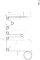
Figure 2 is a schematic side view of the packaging machine ofFigure 1 ; and -
Figure 3 is a perspective view, with parts removed for clarity, of a forming unit for forming a tube from a web of packaging material in accordance with the present invention. -
Figures 1 and2 disclose, as a whole, apackaging machine 1 for continuously producing sealed packages, containing a pourable food product, such as for example pasteurized or long-life (UHT) milk, tomato sauce, wine, fruit juice. The sealed packages are obtained from a packaging material unwound from a reel 3 and fed along a conveying path P. When unwound from the reel 3, the packaging material has the shape of a continuousplanar web 4 of packaging material. - Typically, the packaging material has a multi-layer structure. More specifically, the packaging material may comprise at least a layer of fibrous material, such as for example a paper or cardboard layer, and at least two layers of heat-seal plastic material, e.g. polyethylene, with the layer of fibrous material interposed between them. One of these two layers of heat-seal plastic material may define the inner face of the packages eventually contacting the pourable product.
- According to some possible non-limiting embodiments, the packaging material may also comprise a layer of gas-and light-barrier material, e.g. aluminum foil or ethylene vinyl alcohol (EVOH) film, which, in particular, is arranged between one of the layers of heat-seal plastic material and the layer of fibrous material. Preferably, the packaging material may also comprise a further layer of heat-seal plastic material interposed between the layer of gas- and light-barrier material and the layer of fibrous material.
- The
web 4 of packaging material is fed to a sterilizingunit 5 by means of guiding elements 6, in particular by a number of rollers 6 (one of said rollers is illustrated infigure 2 ). The sterilizingunit 5 has a sterilizingbath 7, in which a chemical sterilizing agent, such as a hydrogen peroxide solution, is applied to theweb 4 of packaging material. Theweb 4 of packaging material is fed through the sterilizingunit 5 by means of known guiding elements 8, like for example rollers 8 or similar elements. - The
packaging machine 1 further comprises a formingunit 9 arranged downstream of the sterilizingunit 5 along the conveying path P. The formingunit 9 extends substantially vertically along the conveying path P for producing acontinuous tube 10. In particular, inside the formingunit 9, theweb 4 of packaging material is folded from a continuous planar shape to a continuous tubular shape with a longitudinal axis Y. In particular, the longitudinal axis Y is arranged along a vertical direction. - The forming
unit 9 is defined within afixed structure 11 in which theweb 4 of packaging material is maintained in a sterile-air environment. The formingunit 9 further comprises a number of forming/folding devices 12 placed along the conveying path P in succession (one after the other). - Advantageously, each of said folding devices 12 may comprise a ring-like shape, e.g. at least partially enclosing the
web 4 of packaging material. For example, the folding device 12 may comprise a forming ring 13 surrounding theweb 4 of packaging material. The supporting device 12 may be configured for supporting a number of rollers 14 cooperating to fold theweb 4 of packaging material. - In particular, the forming
unit 9 comprises a (first)folding device 12A and a (second)folding device 12B placed along the conveying path P in succession (one after the other) carried by thefixed structure 11, and interacting with theweb 4 of packaging material to fold theweb 4 of packaging material gradually into a tube (cylinder) and superimpose a (first)lateral portion 4A of theweb 4 of packaging material to a (second)lateral portion 4B of theweb 4 of packaging material, opposite the (first)lateral portion 4A, to form thecontinuous tube 10. - The
folding device 12B is placed downstream of thefolding device 12A along the conveying path P. - With particular reference to
figures 1 and 4, thefirst folding device 12A comprises thefirst folding ring 13A supporting a plurality offirst folding rollers 14A; saidfirst folding rollers 14A have respective axes perpendicular to the axis Y. Saidfirst folding rollers 14A have respective lateral surfaces with concave shape (i.e. theweb 4 of packaging material encounters a diameter at the ends greater than a diameter at the center of thefirst folding rollers 14A). The lateral surfaces of thefirst folding rollers 14A define a first compulsory passage for theweb 4 of packaging material being folded. - Similarly, the
second folding device 12B comprises thesecond folding ring 13B supporting a plurality ofsecond folding rollers 14B; saidsecond folding rollers 14B have respective axes perpendicular to the axis Y. Saidsecond folding rollers 14B have respective lateral surfaces with concave shape (i.e. theweb 4 of packaging material encounters a diameter at the ends greater than a diameter at the center of thesecond folding rollers 14B). The lateral surfaces of thesecond folding rollers 14A define a second compulsory passage for theweb 4 of packaging material being folded. - The first compulsory passage and the second compulsory passage are different in section. More in detail, the
web 4 of packaging material has a substantially C-shape in the area of thefirst folding device 12A and a substantially circular shape in the area of thesecond folding device 12B. A gap is defined between thelateral portion 4A and thelateral portion 4B of theweb 4 of packaging material which decreases gradually in section along the conveying path P from the first compulsory passage to the second compulsory passage. - The
packaging machine 1 comprises a sealing unit 15 (of the known type and shown schematically infigures 1 and3 ) for sealing overlappinglateral portions web 4 of packaging material to obtain a fluid-tight longitudinal seal in thetube 10. Thesealing unit 15 is arranged downstream of thefirst folding devices 12A along the conveying path P. Advantageously, thesealing unit 15 is interposed between the twofolding devices - The
sealing unit 15 comprises aheating element 16. According to a first embodiment, theheating element 16 comprises aninduction heating element 16 for inductively heating the internal surface of thelateral portion 4A to be superimposed the facing surface of the secondlateral portion 4B. The internal surface of thelateral portion 4A is the surface facing the secondlateral portion 4B. - According to a second embodiment, the
heating element 16 comprises a hotair heating element 16 having a number of nozzles for directing hot air onto the internal surface of thelateral portion 4A to be superimposed the facing surface of the secondlateral portion 4B. - The
heating element 16 is supported by an arm carried by thefixed structure 11. The arm and theheating element 16 are mobile; in particular, the arm and theheating element 16 are mobile between an operating position wherein theheating element 16 is interposed between the twolateral portions lateral portion 4A and a rest position wherein theheating element 16 is away from theweb 4 of packaging material; and vice versa from the rest position to the operating position. More in detail, in the operating position, theheating element 16 is placed in the air gap defined between the twolateral portions heating element 16 is realized for directing heat onto the internal surface of thelateral portion 4A in the operating position. - Along the conveying path P it is defined a sealing region in correspondence of the sealing
unit 15. More in detail, the sealing region is defined along the conveying path P in the area wherein theheating element 16 is interposed between the twolateral portions web 4 of packaging material. - The forming
unit 9 further comprises a number of supporting elements 18, each of which is realized to contact and maintain in a predetermined position at least part of theweb 4 of packaging material. - The supporting elements 18 may be positioned upstream of or at a heating area, wherein the
web 4 of packaging material is heated. - According to a first embodiment, the supporting elements 18 comprise rollers. According to a second embodiment, the supporting elements 18 comprise conical shaped elements (so called "fingers").
- Advantageously, the supporting elements 18 are realized to contact and maintain in a predetermined position the external surface of the
first lateral portion 4A (or edge) of theweb 4 of packaging material to be heated. - Alternatively, the supporting elements 18 are advantageously realized to contact and maintain in a predetermined position at a predetermined distance from heat the external surface of the second
lateral portion 4B (or edge) of theweb 4 of packaging material. The external surface of secondlateral portion 4B is the surface facing thefirst lateral portion 4A. - More in detail, supporting elements 18 comprise at least a superior supporting element 18A. Said superior supporting
element 18A is placed in the area of thefolding device 12A. - According to a possible embodiment, the superior supporting
element 18A comprisesfolding rollers 14A which are realized to contact and maintain in a predetermined position at least part of theweb 4 of packaging material. In particular,folding rollers 14A are realized to contact and maintain in a predetermined position the external surface of theweb 4 of packaging material. In other words, the superior supportingelement 18A may be integrated into the formingring 13A. - The supporting elements 18 may comprise an intermediate supporting element 18B. Said intermediate supporting
element 18B is placed downstream of thefolding device 12A along the conveying path P. - Advantageously, the intermediate supporting
element 18B is attached/connected to thefirst folding device 12A, i.e. to thefirst folding ring 13A. Alternatively, the intermediate supportingelement 18B is advantageously arranged at a distance with respect to thefolding device 12A and attached thereto by means of a fixedarm 19. The intermediate supportingelement 18B is realized to contact and maintain in a predetermined position the external surface of theweb 4 of packaging material; in particular, the intermediate supportingelement 18B is realized to contact and maintain in a predetermined position the external surface of thelateral portions 4A. - According to a possible embodiment, the intermediate supporting
element 18B comprises a number ofrollers 20 carried by thearm 19. Preferably, the number ofrollers 20 is comprised within one and four. Thearm 19 projects downwards along the conveying path P towards thefolding device 12B. Thearm 19 is connected to thestructure 11; preferably, thearm 19 is connected to thefolding ring 13A. The arm 19 (and, as a consequence, the rollers 20) is arranged in a fixed position with respect to thetube 10; the arm 19 (and, as a consequence, the rollers 20) is arranged in a fixed position with respect to the folding devices 12. Therollers 20 are arranged in succession one after the other, with their axis parallel one to another, in the area of the sealing region. - Advantageously, the supporting elements 18 are in a fixed position. The movable parts of the forming unit and/or sealing unit relatively move with respect to the supporting elements 18.
- Finally, the
tube 10 is continuously filled with the pourable food product through a pourconduit 21, which partially extends inside thetube 10 and is part of a filling circuit. Thetube 10 is sent to a transverse forming sealing unit (not shown), in which thetube 10 is gripped to transversely seal the tube and form pillow packs 2. Finally, the pillow packs 2 are subjected to successive mechanical folding operations to obtain the finished sealed packages. - In all the embodiments described above, the supporting element 18 (either superior, intermediate or inferior) is arranged in a fixed position with respect to the folding devices 12.
- The normal operation of the
packaging machine 1 comprises the step of positioning theheating element 16 in the operating position wherein theheating element 16 is interposed between the twolateral portions lateral portion 4A at the packaging material. During the normal operation of thepackaging machine 1, theheating element 16 is placed in the gap defined between the twolateral portions lateral portion 4A in the operating position. - When the advancement of the
web 4 of packaging material along the conveying path P is interrupted, theheating element 16 is moved from the operating position to the rest position wherein theheating element 16 is away from theweb 4 of packaging material, thereby avoiding directing too much heat onto the internal surface of thelateral portion 4A. The supporting elements 18 maintain in a fixed and predetermined position theweb 4 of packaging material for the time in which theheating element 16 is arranged in the rest position. Finally, when the advancement of theweb 4 of packaging material along the conveying path P resumes, theheating element 16 is moved from the rest position to the operating position. -
- 1
- packaging machine
- 2
- pillow pack
- 3
- reel
- 4
- web of packaging material
- 4A,4B
- lateral portion
- 5
- sterilizing unit
- 6
- guiding element
- 7
- sterilizing bath
- 8
- guiding element
- 9
- forming unit
- 10
- tube
- 11
- structure
- 12,12A,12B
- folding device
- 13,13A,13B
- forming ring
- 14,14A,14B
- folding roller
- 15
- sealing unit
- 16
- heating element
- 18,18A,18B
- supporting element
- 19
- arm
- 20
- roller
- 21
- pour conduit
- P
- conveying path
- Y
- axis
Claims (13)
- A forming unit (9) for folding a web (4) of packaging material into a tube (10) and superimpose a first lateral portion (4A) of the web (4) of packaging material to a second lateral portion (4B) of the web (4) of packaging material comprising:- a number of forming devices (12) placed along a conveying path (P) in succession and configured to fold the web (4); and- a plurality of supporting elements (18) configured to contact and maintain in a predetermined position said first and second lateral portion (4A, 4B) of the web (4) of packaging material; wherein said plurality of supporting elements (18) is arranged in a fixed position with respect to the forming devices (12).
- A forming unit according to claim 1, wherein the supporting elements (18) comprise rollers or conical shaped elements ("fingers").
- A forming unit according to claim 1 or 2, wherein at least a supporting element (18) is realized to contact and maintain in a predetermined position an external surface of the first lateral portion (4A) and/or a surface of the second lateral portion (4B) facing the first lateral portion (4A).
- A forming unit according to anyone of the previous claims, wherein each forming device (12) supports a number of folding rollers (14) cooperating with each other to fold the web (4) of packaging material; and wherein the supporting elements (18) comprise a folding roller (14).
- A forming unit according to anyone of the previous claims, wherein at least a first supporting element (18) is connected/attached to a first forming device (12).
- A forming unit according to anyone of the previous claims, wherein at least a second supporting element (18) is arranged at a distance from a second forming device (12); preferably, the second supporting element (18) is arranged on an arm connected to the second forming device (12) .
- A forming unit according to anyone of the previous claims and comprising a plurality of supporting elements (18) arranged along the conveying path (P) in succession, preferably interposed between two forming devices (12).
- A forming unit according to anyone of the previous claims wherein each forming device (12) is substantially ring shaped and at least partially encloses the web (4) of packaging material being folded.
- An apparatus for producing a sealed tube (10) of packaging material comprising a forming unit (9) realized according to anyone of the claim from 1 to 8 and a sealing unit (15) for sealing overlapping first and second lateral portions (4A, 4B) arranged along the conveying path (P) in a sealing region; wherein the sealing unit (15) is preferably interposed between two forming devices (12).
- An apparatus according to claim 9 wherein the sealing unit (15) comprises a heating element (16) supported by an arm movable between an operating position wherein the heating element (16) is interposed between the first and second lateral portions (4A, 4B) and facing an internal surface of the first lateral portion (4A) and a rest position wherein the heating element (16) is away from the web (4) of packaging material; and vice versa from the rest position to the operating position.
- An apparatus according to claim 10, wherein the heating element (16) comprises an induction heating element (16) for inductively heating the internal surface of the first lateral portion (4A) and/or a hot air heating element (16) having a number of nozzles for directing hot air onto the internal surface of the first lateral portion (4A).
- A packaging machine (1) for producing sealed packages from a packaging material fed along the conveying path (P), the packaging (1) machine comprising an apparatus realized according to anyone of claims 9 to 11.
- A method to operate an apparatus realized according to anyone of claims 9 to 11 and comprising the steps of:- arranging the sealing unit (15) in an operating position interposed between the first and second lateral portions (4A, 4B) and facing an internal surface of the first lateral portion (4A) so as to direct heat onto the internal surface of the first lateral portion (4A);- when the advancement of the web (4) of packaging material along the conveying path (P) is interrupted, moving the sealing unit (15) in a rest position away from the web (4) of packaging material, thereby avoiding directing too much heat onto the internal surface of first lateral portion (4A) and maintaining in a fixed and predetermined position the web (4) of packaging material by means of said plurality of supporting elements (18); and- when the advancement of the web (4) of packaging material along the conveying path (P) resumes, moving the sealing unit (15) back to the operating position.
Applications Claiming Priority (1)
| Application Number | Priority Date | Filing Date | Title |
|---|---|---|---|
| IT102023000019347A IT202300019347A1 (en) | 2023-09-20 | 2023-09-20 | A UNIT FOR FORMING A TUBE FROM A STRIP OF PACKAGING MATERIAL, AN APPARATUS FOR PRODUCING A SEALED TUBE PROVIDED WITH SAID FORMING UNIT, A PACKAGING MACHINE WITH SAID APPARATUS AND A METHOD FOR OPERATION OF SAID APPARATUS |
Publications (1)
| Publication Number | Publication Date |
|---|---|
| EP4527749A1 true EP4527749A1 (en) | 2025-03-26 |
Family
ID=88838886
Family Applications (1)
| Application Number | Title | Priority Date | Filing Date |
|---|---|---|---|
| EP24190462.2A Pending EP4527749A1 (en) | 2023-09-20 | 2024-07-23 | Forming unit for forming a tube from a web of packaging material, an apparatus for producing a sealed tube provided with said forming unit, a packaging machine with said apparatus and a method to operate said apparatus |
Country Status (3)
| Country | Link |
|---|---|
| EP (1) | EP4527749A1 (en) |
| IT (1) | IT202300019347A1 (en) |
| WO (1) | WO2025061349A1 (en) |
Citations (5)
| Publication number | Priority date | Publication date | Assignee | Title |
|---|---|---|---|---|
| US6397557B1 (en) * | 2000-01-17 | 2002-06-04 | Tetra Laval Holdings & Finance S.A. | Packaging machine for producing sealed packages of pourable food products |
| US11235896B2 (en) * | 2017-09-27 | 2022-02-01 | Tetra Laval Holdings & Finance S.A. | Packaging apparatus for forming sealed packages |
| WO2023094938A1 (en) * | 2021-11-25 | 2023-06-01 | G.D S.P.A | Apparatus for making containers filled with a liquid and sealed |
| EP4197751A1 (en) * | 2021-12-17 | 2023-06-21 | Tetra Laval Holdings & Finance S.A. | Packaging assembly for forming and sealing a plurality of packs containing a pourable product |
| US20230242289A1 (en) * | 2020-07-23 | 2023-08-03 | Tetra Laval Holdings & Finance S.A. | Package forming unit, packaging apparatus having a package forming unit and method for forming packages |
-
2023
- 2023-09-20 IT IT102023000019347A patent/IT202300019347A1/en unknown
-
2024
- 2024-07-23 EP EP24190462.2A patent/EP4527749A1/en active Pending
- 2024-07-23 WO PCT/EP2024/070937 patent/WO2025061349A1/en active Pending
Patent Citations (5)
| Publication number | Priority date | Publication date | Assignee | Title |
|---|---|---|---|---|
| US6397557B1 (en) * | 2000-01-17 | 2002-06-04 | Tetra Laval Holdings & Finance S.A. | Packaging machine for producing sealed packages of pourable food products |
| US11235896B2 (en) * | 2017-09-27 | 2022-02-01 | Tetra Laval Holdings & Finance S.A. | Packaging apparatus for forming sealed packages |
| US20230242289A1 (en) * | 2020-07-23 | 2023-08-03 | Tetra Laval Holdings & Finance S.A. | Package forming unit, packaging apparatus having a package forming unit and method for forming packages |
| WO2023094938A1 (en) * | 2021-11-25 | 2023-06-01 | G.D S.P.A | Apparatus for making containers filled with a liquid and sealed |
| EP4197751A1 (en) * | 2021-12-17 | 2023-06-21 | Tetra Laval Holdings & Finance S.A. | Packaging assembly for forming and sealing a plurality of packs containing a pourable product |
Also Published As
| Publication number | Publication date |
|---|---|
| WO2025061349A1 (en) | 2025-03-27 |
| IT202300019347A1 (en) | 2025-03-20 |
Similar Documents
| Publication | Publication Date | Title |
|---|---|---|
| US11104462B2 (en) | Guiding device | |
| EP3656687B1 (en) | A method and a packaging apparatus for forming sealed packages | |
| JP7787871B2 (en) | Package forming unit, packaging device having package forming unit, and package forming method | |
| EP4032819B1 (en) | Infeed conveyor for a folding apparatus, folding apparatus having an infeed conveyor and packaging machine having a folding apparatus | |
| EP3461749A2 (en) | A packaging apparatus for forming sealed packages | |
| US20220177173A1 (en) | Packaging machine for producing sealed packages | |
| JP2025521902A (en) | Conveying device for packaging machine, packaging machine having the conveying device, and carrier for the conveying device | |
| WO2025061349A1 (en) | Forming unit for forming a tube from a web of packaging material, an apparatus for producing a sealed tube provided with said forming unit, a packaging machine with said apparatus and a method to operate said apparatus | |
| EP4265533A1 (en) | Infeed conveyor for a folding apparatus, folding apparatus having an infeed conveyor and packaging machine having a folding apparatus | |
| EP4588646A1 (en) | Apparatus for applying a sealing strip of a heat-sealable material to a web of packaging material and packaging machine for forming sealed packages | |
| EP4588648A1 (en) | Apparatus and method for applying a sealing strip of a heat-sealable material to a web of packaging material, packaging machine for forming sealed packages | |
| EP4606749A1 (en) | Splicing unit for splicing a sealing strip of heat-sealable material, apparatus for applying a sealing strip to a web of packaging material and packaging machine for forming sealed packages | |
| EP4474299A1 (en) | Package forming apparatus and packaging machine for forming packages | |
| EP4606751A1 (en) | Buffer unit of a web of packaging material for a packaging machine and packaging machine for forming sealed packages | |
| EP4549329A1 (en) | Package forming apparatus for a packaging machine and packaging machine for forming packages filled with a pourable product | |
| EP4656538A1 (en) | Folding apparatus, packaging machine having a folding apparatus and method for forming finalized packages from semi-finalized packs | |
| EP4410690B1 (en) | Package forming apparatus for a packaging machine and packaging machine for forming packages filled with a pourable product | |
| EP4644097A1 (en) | Device for directing a heated air flow towards a web of packaging material, forming and sealing unit for forming a tube from a web of packaging material and packaging machine for producing sealed packages from a packaging material | |
| EP4656539A1 (en) | Folding apparatus, packaging machine having a folding apparatus and method for forming finalized packages from semi-finalized packs | |
| EP4410522A1 (en) | Package forming apparatus for a packaging machine and packaging machine for forming packages filled with a pourable product | |
| EP4458689A1 (en) | Package forming apparatus for a packaging machine, packaging machine for forming packages filled with a pourable product and method for forming packages | |
| CN120752181A (en) | Packaging device for forming a plurality of sealed packages filled with pourable product | |
| JP2026504441A (en) | Magazine unit for packaging machine, packaging machine equipped with magazine unit, and method of operating magazine unit for packaging machine | |
| WO2025247747A1 (en) | Folding apparatus, packaging machine having a folding apparatus and method for forming finalized packages from semi-finalized packs |
Legal Events
| Date | Code | Title | Description |
|---|---|---|---|
| PUAI | Public reference made under article 153(3) epc to a published international application that has entered the european phase |
Free format text: ORIGINAL CODE: 0009012 |
|
| STAA | Information on the status of an ep patent application or granted ep patent |
Free format text: STATUS: THE APPLICATION HAS BEEN PUBLISHED |
|
| AK | Designated contracting states |
Kind code of ref document: A1 Designated state(s): AL AT BE BG CH CY CZ DE DK EE ES FI FR GB GR HR HU IE IS IT LI LT LU LV MC ME MK MT NL NO PL PT RO RS SE SI SK SM TR |
|
| STAA | Information on the status of an ep patent application or granted ep patent |
Free format text: STATUS: REQUEST FOR EXAMINATION WAS MADE |
|
| 17P | Request for examination filed |
Effective date: 20250926 |