EP4527747A1 - Satellite gripper - Google Patents
Satellite gripper Download PDFInfo
- Publication number
- EP4527747A1 EP4527747A1 EP24201747.3A EP24201747A EP4527747A1 EP 4527747 A1 EP4527747 A1 EP 4527747A1 EP 24201747 A EP24201747 A EP 24201747A EP 4527747 A1 EP4527747 A1 EP 4527747A1
- Authority
- EP
- European Patent Office
- Prior art keywords
- grasping
- envelope
- support structure
- finger
- guides
- Prior art date
- Legal status (The legal status is an assumption and is not a legal conclusion. Google has not performed a legal analysis and makes no representation as to the accuracy of the status listed.)
- Pending
Links
Images






Classifications
-
- B—PERFORMING OPERATIONS; TRANSPORTING
- B64—AIRCRAFT; AVIATION; COSMONAUTICS
- B64G—COSMONAUTICS; VEHICLES OR EQUIPMENT THEREFOR
- B64G1/00—Cosmonautic vehicles
- B64G1/22—Parts of, or equipment specially adapted for fitting in or to, cosmonautic vehicles
- B64G1/64—Systems for coupling or separating cosmonautic vehicles or parts thereof, e.g. docking arrangements
- B64G1/646—Docking or rendezvous systems
- B64G1/6462—Docking or rendezvous systems characterised by the means for engaging other vehicles
-
- B—PERFORMING OPERATIONS; TRANSPORTING
- B64—AIRCRAFT; AVIATION; COSMONAUTICS
- B64G—COSMONAUTICS; VEHICLES OR EQUIPMENT THEREFOR
- B64G1/00—Cosmonautic vehicles
- B64G1/22—Parts of, or equipment specially adapted for fitting in or to, cosmonautic vehicles
- B64G1/64—Systems for coupling or separating cosmonautic vehicles or parts thereof, e.g. docking arrangements
- B64G1/646—Docking or rendezvous systems
-
- B—PERFORMING OPERATIONS; TRANSPORTING
- B25—HAND TOOLS; PORTABLE POWER-DRIVEN TOOLS; MANIPULATORS
- B25J—MANIPULATORS; CHAMBERS PROVIDED WITH MANIPULATION DEVICES
- B25J15/00—Gripping heads and other end effectors
-
- B—PERFORMING OPERATIONS; TRANSPORTING
- B64—AIRCRAFT; AVIATION; COSMONAUTICS
- B64G—COSMONAUTICS; VEHICLES OR EQUIPMENT THEREFOR
- B64G1/00—Cosmonautic vehicles
- B64G1/10—Artificial satellites; Systems of such satellites; Interplanetary vehicles
- B64G1/1078—Maintenance satellites
-
- B—PERFORMING OPERATIONS; TRANSPORTING
- B64—AIRCRAFT; AVIATION; COSMONAUTICS
- B64G—COSMONAUTICS; VEHICLES OR EQUIPMENT THEREFOR
- B64G1/00—Cosmonautic vehicles
- B64G1/22—Parts of, or equipment specially adapted for fitting in or to, cosmonautic vehicles
- B64G1/222—Parts of, or equipment specially adapted for fitting in or to, cosmonautic vehicles for deploying structures between a stowed and deployed state
-
- B—PERFORMING OPERATIONS; TRANSPORTING
- B64—AIRCRAFT; AVIATION; COSMONAUTICS
- B64G—COSMONAUTICS; VEHICLES OR EQUIPMENT THEREFOR
- B64G4/00—Tools specially adapted for use in space
-
- B—PERFORMING OPERATIONS; TRANSPORTING
- B64—AIRCRAFT; AVIATION; COSMONAUTICS
- B64G—COSMONAUTICS; VEHICLES OR EQUIPMENT THEREFOR
- B64G4/00—Tools specially adapted for use in space
- B64G2004/005—Robotic manipulator systems for use in space
Definitions
- the invention consists of a gripper intended for gripping satellites in outer space
- the problem often occurring when intercepting a satellite which requires servicing in the absence of gravity with the use of a servicing satellite's gripper is the simultaneous rotation of the captured satellite relative to the gripper in three axes. This prevents the full synchronization of the gripper with the satellite element by which it can be safely gripped.
- the element in question can be a launch adapter ring (LAR) connecting the satellite with the launch vehicle due to its high level of rigidity and the fact that it is not covered by thermal insulation.
- LAR launch adapter ring
- the aforementioned lack of full synchronization means that with every attempt to grip the satellite, errors of the position and orientation of the gripper relative to the adapter will occur.
- Another problem is the differences in the shape of the cross-section between different types of LAR which make gripping the satellite difficult.
- Exemplary solutions of satellite grippers are disclosed in US6840481 , US2013/0249229 , US2015/314893 and US4718709 .
- the gripper that is closest to the invention is the one manufactured by the company OHB, the concept of which was presented on an international conference and disclosed in scientific publication titled " OHB Gripper Design and Grapple Simulations" [ESA 25.05.2016 Clean Space Industrial Day ].
- Such known gripper is intended for gripping one type of satellite adapter called Envisat LAR.
- the gripper consists of a support structure with two counter-directional carts moving linearly relative to the support structure using linear guides.
- the carts are driven by a screw gear consisting of a counter-threaded drive shaft and of a first and a second nut mounted on the first and the second cart, respectively.
- Each cart consists of linear finger guides situated at 75 degrees relative to the axis of the guides of the support structure.
- Each cart has one finger extending in free state from the cart through the action of a spring element.
- the flat central section of the support structure, parallel to the axis of the guides of the support structure, and the cart fingers delineate the bottom and two sides of the satellite launch adapter grasping envelope, respectively, with access to the aforementioned grasping envelope from the side opposite to the aforementioned bottom.
- the grasping envelope is equipped with sensors which detect the presence of the adapter of the satellite being gripped inside the grasping envelope.
- the purpose of the invention was to develop a gripper able to grip adapters with different cross-section shapes.
- a gripper consisting of a support structure with two counter-directional carts moving linearly relative to the support structure using linear roller guides and driven by a screw gear.
- the screw gear consists of a counter-threaded drive shaft and of a first and a second nut related to the first and the second cart, respectively.
- Each cart contains of linear finger guides situated at an angle relative to the axis of the guides of the support structure.
- On the aforementioned finger guides there are retractable gripper fingers installed which extend in free state from the carts through the action of spring elements.
- the grasping envelope is equipped with sensors which detect the presence of the adapter of the satellite being gripped inside the grasping envelope.
- the invention consists in the fact that each cart has two independent fingers and two parallel linear guides for the fingers. Each linear guide of each cart is situated at the same angle relative to the axis of the guides of the support structure. Each finger has a distal end and a proximal end defined relative to the distance from the entry into the grasping envelope.
- each finger has at least two sensors detecting the presence of the adapter in the grasping envelope.
- the invention simplifies the satellite gripping procedure, since it does not require precise initial positioning of the gripping satellite relative to the satellite being gripped, but nevertheless causes the gripper to be closed on the adapter of the satellite being gripped in the planned position.
- Design of the gripper according to the invention including four independently moving fingers, makes it possible to quickly and efficiently grip differently shaped adapters.
- the high gripping velocity eliminates the risk of escape from the grasping envelope of the adapter which can maintain the correct position for a very short period of time.
- the self-locking property of the screw gear driving the gripper according to the invention makes it possible to maintain the grip of the fingers on the adapter without the need of using the motor.
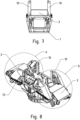
- Fig.8 shows the gripper from Fig.5 in axonometric view from the top
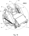
- Fig.9 and Fig.10 show magnified sections of the view from Fig.8
- Fig.11 shows an axonometric view similar to the view in Fig.8 but with the fingers maximally closed
- Fig.12 and Fig.13 show magnified sections of the view in Fig.11
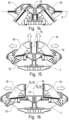
- Figures from Fig.14 to Fig.19 show, in view similar to Fig.
- the embodiment of the gripper comprises a support structure 1 with two counter-directional carts 2 and 3 moving on linear guides 4 mounted on support structure 1.
- the carts 2 and 3 move along the guides 4 with the use of a screw gear which consists of a drive shaft 5, which is counter-threaded on both sides, and of a first 6 and a second 7 nut mounted rigidly on the first 2 and the second 3 cart, respectively.
- Each cart 2 and 3 consists of two linear guides 8 situated at an angle relative to the axis 9 of the guides 4 of the support structure 1.
- a finger 10 of the gripper is slidingly installed. Each finger 10 in its free state, i.e.
- Each linear guide 8 is positioned relative to the axis 9 of the guides 4 of the support structure 1 at the same angle ⁇ of 55 degrees, whereby the angle may be within the range from 46 to 60 degrees.
- Each finger 10 has a distal end 16 and a proximal end 17, whereby the distance defining the ends refers to their distance from the entrance into the grasping envelope 15.
- the two sides 14 of the grasping envelope 15 are delineated by the gripping surfaces 14' of the fingers 10 which in principle are perpendicular to the bottom 13 of the grasping envelope 15.
- the gripping surface 14' of each finger 10 in the vicinity of the proximal end 17 of this finger has a protrusion 18 directed towards the grasping envelope 15.
- the spring 12 of each finger 10 is mounted on the support structure 1 in the vicinity of the distal end 16 of this finger 10.
- the sensors 19 detecting the presence of the adapter 11 in the grasping envelope 15 are optical sensors operating in the infrared range, consisting of a light-emitting diode and a photodiode.
- the sensors 19 are mounted on fingers 10, at least two for each finger 10.
- On the support structure 1 of the gripper there are limit switches 20 which are activated by carts 2 and 3 when they are maximally spreaded from each other. Also each cart 2 and 3 has limit switches 21 which are activated by fingers 10 when they are maximally extended upwards during movement along the guides 8.
- the carts 2 and 3 move outwards (on the drawing to the left and right, respectively), accompanied by the movement of fingers 10 along the guides 8, causing them to extend upwards ( Fig.15 ).
- the movements of carts 2 and 3, and fingers 10 are indicated by arrows.
- the carts 2 and 3 continue to slide away from each other until the maximum opening of the gripper is achieved ( Fig.16 ).
- the adapter 11 enters the grasping envelope ( Fig.17 ), as signalled by sensors 19, the rotation of the motor 23 is switched and the gripper starts to close. In this phase, first only the carts 2 and 3 move (on the drawing to the left and right, respectively) until all fingers 10 come into contact with the adapter 11.
- the gripper positioning relative to the adapter 11 may still be inaccurate. Further closing of the gripper causes the fingers 10 to clamp on the adapter 11 ( Fig.18 ), while during the clamping, the movement of the carts 2 and 3 is accompanied by the movement of the fingers 10 along the guides 8, causing them to move downwards. During this closing phase, any potential errors of relative positioning of the gripper and the adapter 11 can be further corrected. Furthermore, the horizontal spacing of the fingers 10 during the closing of the gripper automatically adjusts to the dimensions of the adapter 11, arising from the difference between its inner and outer diameter.
Landscapes
- Engineering & Computer Science (AREA)
- Remote Sensing (AREA)
- Aviation & Aerospace Engineering (AREA)
- Physics & Mathematics (AREA)
- Astronomy & Astrophysics (AREA)
- General Physics & Mathematics (AREA)
- Robotics (AREA)
- Mechanical Engineering (AREA)
- Manipulator (AREA)
Abstract
Description
- The invention consists of a gripper intended for gripping satellites in outer space
- The problem often occurring when intercepting a satellite which requires servicing in the absence of gravity with the use of a servicing satellite's gripper is the simultaneous rotation of the captured satellite relative to the gripper in three axes. This prevents the full synchronization of the gripper with the satellite element by which it can be safely gripped. The element in question can be a launch adapter ring (LAR) connecting the satellite with the launch vehicle due to its high level of rigidity and the fact that it is not covered by thermal insulation. The aforementioned lack of full synchronization means that with every attempt to grip the satellite, errors of the position and orientation of the gripper relative to the adapter will occur. Another problem is the differences in the shape of the cross-section between different types of LAR which make gripping the satellite difficult. Exemplary solutions of satellite grippers are disclosed in
US6840481 ,US2013/0249229 ,US2015/314893 andUS4718709 . The gripper that is closest to the invention is the one manufactured by the company OHB, the concept of which was presented on an international conference and disclosed in scientific publication titled "OHB Gripper Design and Grapple Simulations" [ESA 25.05.2016 Clean Space Industrial Day]. Such known gripper is intended for gripping one type of satellite adapter called Envisat LAR. The gripper consists of a support structure with two counter-directional carts moving linearly relative to the support structure using linear guides. The carts are driven by a screw gear consisting of a counter-threaded drive shaft and of a first and a second nut mounted on the first and the second cart, respectively. Each cart consists of linear finger guides situated at 75 degrees relative to the axis of the guides of the support structure. Each cart has one finger extending in free state from the cart through the action of a spring element. The flat central section of the support structure, parallel to the axis of the guides of the support structure, and the cart fingers delineate the bottom and two sides of the satellite launch adapter grasping envelope, respectively, with access to the aforementioned grasping envelope from the side opposite to the aforementioned bottom. The grasping envelope is equipped with sensors which detect the presence of the adapter of the satellite being gripped inside the grasping envelope. - The purpose of the invention was to develop a gripper able to grip adapters with different cross-section shapes.
- This purpose is fulfilled by a gripper consisting of a support structure with two counter-directional carts moving linearly relative to the support structure using linear roller guides and driven by a screw gear. The screw gear consists of a counter-threaded drive shaft and of a first and a second nut related to the first and the second cart, respectively. Each cart contains of linear finger guides situated at an angle relative to the axis of the guides of the support structure. On the aforementioned finger guides, there are retractable gripper fingers installed which extend in free state from the carts through the action of spring elements. The flat central section of the support structure, parallel to the axis of the guides of the support structure, and the cart fingers delineate the bottom and two sides of the satellite launch adapter grasping envelope, respectively, with access to the aforementioned grasping envelope from the side opposite to the aforementioned bottom. The grasping envelope is equipped with sensors which detect the presence of the adapter of the satellite being gripped inside the grasping envelope. The invention consists in the fact that each cart has two independent fingers and two parallel linear guides for the fingers. Each linear guide of each cart is situated at the same angle relative to the axis of the guides of the support structure. Each finger has a distal end and a proximal end defined relative to the distance from the entry into the grasping envelope. The two sides of the grasping envelope are delineated by the gripping surfaces of the fingers which are substantially perpendicular to the bottom of the grasping envelope. The gripping surface of each finger in the vicinity of the proximal end of this finger has a protrusion directed towards the grasping envelope. The spring element of each finger is an extendable coil spring spanning between the support structure of the gripper and the distal end of the finger. The sensors detecting the presence of the adapter in the grasping envelope are optical sensors, advantageously operating in the infrared range.
- In one of variants of the invention, the angle of the finger guide is between 46 and 60 degrees, advantageously the angle is 55 degrees.
- In next variant of the invention, each finger has at least two sensors detecting the presence of the adapter in the grasping envelope.
- In next variant of the invention, there are limit switches on the support structure which are activated by the carts at the moment of the greatest spread between them. Each cart is equipped with limit switches which are activated by the gripper fingers when they are maximally extended.
- In another variant of the invention, the drive shaft is driven by an electric motor, advantageously by a direct current electric motor, using a gearbox.
- In yet another variant of the invention, the electric motor is equipped with an encoder.
- The invention simplifies the satellite gripping procedure, since it does not require precise initial positioning of the gripping satellite relative to the satellite being gripped, but nevertheless causes the gripper to be closed on the adapter of the satellite being gripped in the planned position. Design of the gripper according to the invention, including four independently moving fingers, makes it possible to quickly and efficiently grip differently shaped adapters. The high gripping velocity eliminates the risk of escape from the grasping envelope of the adapter which can maintain the correct position for a very short period of time. The self-locking property of the screw gear driving the gripper according to the invention makes it possible to maintain the grip of the fingers on the adapter without the need of using the motor.
- Example of the invention is described in detail below and shown on the figures of drawings.
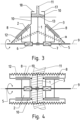
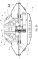
Fig.1 and Fig.2 show the side view and top view, respectively, of the kinematic diagram of the gripper according to the invention, with maximally extended fingers and the adapter of the satellite being gripped inside the grasping envelope.Fig.3 and Fig.4 show the side view and top view, respectively, of the kinematic diagram of the gripper according to the invention, with fingers clamped on the adapter of the satellite being gripped.Fig.5, Fig.6 andFig.7 show the exemplary embodiment of the gripper according to the invention, with maximally extended fingers, in longer side view, top view and shorter side view, respectively.Fig.8 shows the gripper fromFig.5 in axonometric view from the top, whereasFig.9 andFig.10 show magnified sections of the view fromFig.8 .Fig.11 shows an axonometric view similar to the view inFig.8 but with the fingers maximally closed, whereasFig.12 andFig.13 show magnified sections of the view inFig.11 . Figures fromFig.14 to Fig.19 show, in view similar toFig. 5 , the subsequent phases of movement of the gripper fingers, starting from empty gripper with closed fingers (Fig.14 ), through the opening of the gripper (Fig.15 and Fig.16 ) in order to enclose the adapter in the grasping envelope (Fig.17 ), to gripping the aforementioned adapter and closing the gripper fingers on it (Fig.18 and Fig. 19 ).Fig.20 shows the horizontal plane cross-section of the gripper withFig. 5 . - The embodiment of the gripper according to the invention comprises a
support structure 1 with twocounter-directional carts linear guides 4 mounted onsupport structure 1. Thecarts guides 4 with the use of a screw gear which consists of adrive shaft 5, which is counter-threaded on both sides, and of a first 6 and a second 7 nut mounted rigidly on the first 2 and the second 3 cart, respectively. Eachcart linear guides 8 situated at an angle relative to theaxis 9 of theguides 4 of thesupport structure 1. On each of theaforementioned guides 8, afinger 10 of the gripper is slidingly installed. Eachfinger 10 in its free state, i.e. without contact with theadapter 11 of the satellite being gripped, extends from itscart extendable coil spring 12 spanning between thefinger 10 and thesupport structure 1. The flat central section of thesupport structure 1 is parallel to theaxis 9 of theguides 4 of thesupport structure 1. The central section of thesupport structure 1 andfingers 10 ofcarts bottom 13 and the twosides 14 of thesatellite grasping envelope 15, respectively. The entrance to thegrasping envelope 15 is located opposite theaforementioned bottom 13. Thegrasping envelope 15 is equipped with sensors which detect the presence of theadapter 11 of the satellite being gripped inside the grasping envelope. Eachlinear guide 8 is positioned relative to theaxis 9 of theguides 4 of thesupport structure 1 at the same angle α of 55 degrees, whereby the angle may be within the range from 46 to 60 degrees. Eachfinger 10 has a distal end 16 and aproximal end 17, whereby the distance defining the ends refers to their distance from the entrance into thegrasping envelope 15. The twosides 14 of thegrasping envelope 15 are delineated by the gripping surfaces 14' of thefingers 10 which in principle are perpendicular to thebottom 13 of thegrasping envelope 15. The gripping surface 14' of eachfinger 10 in the vicinity of theproximal end 17 of this finger has aprotrusion 18 directed towards thegrasping envelope 15. Thespring 12 of eachfinger 10 is mounted on thesupport structure 1 in the vicinity of the distal end 16 of thisfinger 10. Thesensors 19 detecting the presence of theadapter 11 in thegrasping envelope 15 are optical sensors operating in the infrared range, consisting of a light-emitting diode and a photodiode. Thesensors 19 are mounted onfingers 10, at least two for eachfinger 10. On thesupport structure 1 of the gripper, there arelimit switches 20 which are activated bycarts cart limit switches 21 which are activated byfingers 10 when they are maximally extended upwards during movement along theguides 8. Thedrive shaft 5 is installed on a rotation mount in thesupport structure 1 and driven using a gear set 22 by direct currentelectric motor 23 which is equipped with an encoder, not shown on the drawing. Thesupport structure 1 andfingers 10 are made with aluminium alloy. Theguides drive shaft 5 in one direction causescarts guides 4, sincedrive nuts carts Fingers 10, mounted onguides 8 and not loaded by the pressure onadapter 11 at the moment, extend upwards, pulled bystrained springs 12. Themotor 23 is powered until any of the limit switches 20 and 21 is activated. The rotation of thedrive shaft 5 in opposite direction causescarts fingers 10 make contact with the resistance surfaces of thesupport structure 1, they slide down along theguides 8. The encoder of themotor 23, together with Hall effect sensors, is also used to measure the angular velocity ofmotor 23 and indirectly, also the angular velocity of thedrive shaft 5. The drive unit of the gripper is equipped with a temperature gauge system, not shown on the drawing, which preventsmotor 23 from overheating, and a system for gauging the electric power draw bymotor 23. Since the electric power draw is proportional to the clamping force offingers 10 on theadapter 11, the electric power gauge also measures the clamping force offingers 10 on theadapter 11 without the need for installing separate force sensors. The individual phases of operation of the exemplary gripper are shown on figures fromFig.14 to Fig.19 . Despite the fact that the notions of up and down do not apply to outer space, in order to make the invention more comprehensible, the upper and lower section of the sheet, on which the aforementioned figures are shown, are used, where the axis ofguides 4 is horizontal, thesupport structure 1 is situated in the lower section of the figures and the entrance into the graspingenvelope 15 is situated on the opposite side, i.e. in the upper section. Initially, the gripper is closed (Fig.14 ), i.e. withcarts fingers 10 retracted. Once themotor 23 is powered up, thecarts fingers 10 along theguides 8, causing them to extend upwards (Fig.15 ). The movements ofcarts fingers 10 are indicated by arrows. Once thefingers 10 reach their maximum upward position, thecarts Fig.16 ). When theadapter 11 enters the grasping envelope (Fig.17 ), as signalled bysensors 19, the rotation of themotor 23 is switched and the gripper starts to close. In this phase, first only thecarts fingers 10 come into contact with theadapter 11. During this closing phase, the gripper positioning relative to theadapter 11 may still be inaccurate. Further closing of the gripper causes thefingers 10 to clamp on the adapter 11 (Fig.18 ), while during the clamping, the movement of thecarts fingers 10 along theguides 8, causing them to move downwards. During this closing phase, any potential errors of relative positioning of the gripper and theadapter 11 can be further corrected. Furthermore, the horizontal spacing of thefingers 10 during the closing of the gripper automatically adjusts to the dimensions of theadapter 11, arising from the difference between its inner and outer diameter. When the clamping force of thefingers 10 on theadapter 11 reaches a high value, the fingers continue moving primarily downwards until the gripper is closed and thefingers 10 are securely clamped on the adapter 11 (Fig.19 ). During the final phase of closing of the gripper, any remaining error of gripper positioning relative to theadapter 11 can be corrected. -
- 1 - support structure
- 2 - first cart
- 3 - second cart
- 4 - support structure guide
- 5 - threaded drive shaft
- 6 - first drive nut
- 7 - second drive nut
- 8 - finger guide
- 9 - axis of the support structure guides
- 10 - finger
- 11 - satellite adapter
- 12 - spring
- 13 - bottom of the grasping envelope
- 14 - side of the grasping envelope
- 14' - gripping surface of the fingers
- 15 - grasping envelope
- 16 - distal end of the
finger 10 - 17 - proximal end of the finger
- 18 - finger protrusion
- 19 - sensor detecting the presence of the adapter
- 20 - limit switch of the support structure
- 21 - limit switch of the cart
- 22 - gear set
- 23 - electric motor
Claims (6)
- A satellite gripper consisting of a support structure with two counter-directional carts moving linearly relative to the support structure using linear guides and driven by a screw gear consisting of a drive shaft which is counter-threaded on both sides, and of a first and second nut connected with the first and the second cart, respectively, each cart consists of linear finger guides situated at an angle relative to the axes of the guides of the support structure, on the aforementioned finger guides are mounted the retractable gripper fingers, extending in free state from the cart through the action of a spring elements, the flat central section of the support structure, parallel to the axes of the guides of the support structure, and the cart fingers delineate the bottom and two sides of the satellite grasping envelope, respectively, with access to the aforementioned grasping envelope from the side opposite to the aforementioned bottom, which the grasping envelope is equipped with sensors which detect the presence of the adapter of the satellite being gripped inside the grasping envelope, characterised by that each cart (2, 3) has two independent fingers (10) and two parallel linear guides (8) for the fingers (10), each linear guide (8) of each cart (2, 3) is situated at the same angle (α) relative to the axis (9) of the guides (4) of the support structure (1), each finger (10) has a distal end (16) and a proximal end (17) relative to the entrance into the grasping envelope (15), the two sides (14) of the grasping envelope (15) are delineated by the gripping surfaces (14') of the fingers (10) which are situated substantially perpendicular to the bottom (13) of the grasping envelope (15), the gripping surface (14') of each finger (10) in the vicinity of the proximal end (17) of the finger (10) has a protrusion (18) directed towards the grasping envelope (15), the spring element of each finger (10) is an extendable spring (12) spanning between the support structure (1) of the gripper and the finger (10) in the vicinity of its distal end (16), while the sensors detecting the presence of the adapter (11) in the grasping envelope (15) are optical sensors (19), advantageously operating in the infrared range.
- The gripper according to Claim 1, characterised by that the angle (α) of the guide (8) of the finger (10) is within the range from 46 to 60 degrees, advantageously is 55 degrees.
- The gripper according to claim 1 or 2, characterised by that each finger (10) has at least two sensors (19) detecting the presence of the adapter (11) in the grasping envelope (15).
- The gripper according to claim 1 or 2 or 3, characterised by that the support structure (1) is equipped with limit switches (20) which are activated by the carts (2, 3) when the carts are maximally spreaded, while each cart (2, 3) is equipped with limit switches (21) which are activated by the fingers (10) of the gripper when they reach their maximum extension.
- The gripper according to claim 1 or 2 or 3 or 4, characterised by that the drive shaft (5) is driven by an electric motor (23), advantageously by a direct current electric motor, using a gearbox (22).
- The gripper according to claim 5, characterised by that the electric motor (23) is equipped with an encoder.
Applications Claiming Priority (1)
| Application Number | Priority Date | Filing Date | Title |
|---|---|---|---|
| PL446192A PL249085B1 (en) | 2023-09-20 | 2023-09-20 | Satellite gripper |
Publications (1)
| Publication Number | Publication Date |
|---|---|
| EP4527747A1 true EP4527747A1 (en) | 2025-03-26 |
Family
ID=93562924
Family Applications (1)
| Application Number | Title | Priority Date | Filing Date |
|---|---|---|---|
| EP24201747.3A Pending EP4527747A1 (en) | 2023-09-20 | 2024-09-20 | Satellite gripper |
Country Status (2)
| Country | Link |
|---|---|
| EP (1) | EP4527747A1 (en) |
| PL (1) | PL249085B1 (en) |
Families Citing this family (1)
| Publication number | Priority date | Publication date | Assignee | Title |
|---|---|---|---|---|
| CN121157088B (en) * | 2025-11-20 | 2026-02-10 | 浙江大学 | Grip of double working mode of clamping and enveloping |
Citations (7)
| Publication number | Priority date | Publication date | Assignee | Title |
|---|---|---|---|---|
| US4718709A (en) | 1986-12-16 | 1988-01-12 | The United States Of America As Represented By The Administrator Of The National Aeronautics And Space Administration | Orbital maneuvering vehicle end effectors |
| US6840481B1 (en) | 2003-09-30 | 2005-01-11 | The Aerospace Corporation | Adjustable multipoint docking system |
| US20130249229A1 (en) | 2012-03-19 | 2013-09-26 | Macdonald Dettwiler & Associates Inc. | Spacecraft capture mechanism |
| US20150314893A1 (en) | 2014-05-02 | 2015-11-05 | Macdonald Dettwiler & Associates Inc. | Spacecraft capture mechanism |
| CN106628278A (en) * | 2016-12-16 | 2017-05-10 | 南京航空航天大学 | Non-cooperative target satellite acquisition device and acquisition method |
| US20190077028A1 (en) * | 2016-05-15 | 2019-03-14 | B.G. Negev Technologies And Applications Ltd., At Ben-Gurion University | Convertible frictionless to frictional fingertips for a gripper to improve robotic grasp robustness |
| CN116000967A (en) * | 2023-01-05 | 2023-04-25 | 航天科工空间工程发展有限公司 | A Grabbing Mechanism for Satellite Assembly |
Family Cites Families (2)
| Publication number | Priority date | Publication date | Assignee | Title |
|---|---|---|---|---|
| US10414053B2 (en) * | 2017-03-09 | 2019-09-17 | U.S.A. As Represented By The Administrator Of The National Aeronautics And Space Administration | Robotic gripper for autonomous rendezvous and capture of satellites |
| PL233647B1 (en) * | 2017-09-08 | 2019-11-29 | Przemyslowy Inst Automatyki I Pomiarow Piap | Satellite gripper |
-
2023
- 2023-09-20 PL PL446192A patent/PL249085B1/en unknown
-
2024
- 2024-09-20 EP EP24201747.3A patent/EP4527747A1/en active Pending
Patent Citations (7)
| Publication number | Priority date | Publication date | Assignee | Title |
|---|---|---|---|---|
| US4718709A (en) | 1986-12-16 | 1988-01-12 | The United States Of America As Represented By The Administrator Of The National Aeronautics And Space Administration | Orbital maneuvering vehicle end effectors |
| US6840481B1 (en) | 2003-09-30 | 2005-01-11 | The Aerospace Corporation | Adjustable multipoint docking system |
| US20130249229A1 (en) | 2012-03-19 | 2013-09-26 | Macdonald Dettwiler & Associates Inc. | Spacecraft capture mechanism |
| US20150314893A1 (en) | 2014-05-02 | 2015-11-05 | Macdonald Dettwiler & Associates Inc. | Spacecraft capture mechanism |
| US20190077028A1 (en) * | 2016-05-15 | 2019-03-14 | B.G. Negev Technologies And Applications Ltd., At Ben-Gurion University | Convertible frictionless to frictional fingertips for a gripper to improve robotic grasp robustness |
| CN106628278A (en) * | 2016-12-16 | 2017-05-10 | 南京航空航天大学 | Non-cooperative target satellite acquisition device and acquisition method |
| CN116000967A (en) * | 2023-01-05 | 2023-04-25 | 航天科工空间工程发展有限公司 | A Grabbing Mechanism for Satellite Assembly |
Also Published As
| Publication number | Publication date |
|---|---|
| PL446192A1 (en) | 2025-03-24 |
| PL249085B1 (en) | 2026-02-23 |
Similar Documents
| Publication | Publication Date | Title |
|---|---|---|
| EP4527747A1 (en) | Satellite gripper | |
| EP3248737B1 (en) | Satellites gripper | |
| US9156171B2 (en) | Gripper | |
| CN111975250B (en) | Workpiece rotating device and robot system | |
| US10507576B2 (en) | Industrial robot | |
| US20130239527A1 (en) | Method and a device for handling sample containers | |
| EP3031586A1 (en) | Flexible gripping device for a part stacking system, part stacking system and positioning method for positioning gripping elements for a part stacking system | |
| ES3054098T3 (en) | Centering device | |
| US20220091147A1 (en) | Liquid handling instrument and pipetting head for and method of aspirating and/or dispensing liquids | |
| CN111971247A (en) | Cap applicator/stripper system and method | |
| US11264152B2 (en) | Method and apparatus for robotically routing wires on a harness form board | |
| JP2016515720A (en) | Cable automatic sorting apparatus and cable automatic sorting method | |
| US8870253B2 (en) | Lockout switch apparatus and method | |
| ES2942431T3 (en) | Tray unstacking device with unloading facility | |
| EP0722546A1 (en) | Fall protection device at actuators | |
| US20210125751A1 (en) | Method and apparatus for robotically routing wires on a harness form board | |
| US9366553B2 (en) | Automated insertion of a contact rod into a metallurgical probe | |
| AU2015261656B2 (en) | Immersion device for an optical fiber for measuring the temperature of a melt | |
| CN108543723A (en) | Sorting robot and logistics system | |
| CN113021308B (en) | Hoisting device | |
| CN217264757U (en) | Rotary cover opening mechanism, cover opening and closing device and nucleic acid extraction instrument | |
| CN116986259B (en) | Loading device and storage and transportation system for battery cells | |
| AU2021365157A9 (en) | Automated gripping mechanism | |
| US20240091937A1 (en) | Robot apparatus | |
| CN215202008U (en) | Manipulator and cutting device |
Legal Events
| Date | Code | Title | Description |
|---|---|---|---|
| PUAI | Public reference made under article 153(3) epc to a published international application that has entered the european phase |
Free format text: ORIGINAL CODE: 0009012 |
|
| STAA | Information on the status of an ep patent application or granted ep patent |
Free format text: STATUS: THE APPLICATION HAS BEEN PUBLISHED |
|
| AK | Designated contracting states |
Kind code of ref document: A1 Designated state(s): AL AT BE BG CH CY CZ DE DK EE ES FI FR GB GR HR HU IE IS IT LI LT LU LV MC ME MK MT NL NO PL PT RO RS SE SI SK SM TR |
|
| STAA | Information on the status of an ep patent application or granted ep patent |
Free format text: STATUS: REQUEST FOR EXAMINATION WAS MADE |
|
| 17P | Request for examination filed |
Effective date: 20250912 |
|
| GRAP | Despatch of communication of intention to grant a patent |
Free format text: ORIGINAL CODE: EPIDOSNIGR1 |
|
| STAA | Information on the status of an ep patent application or granted ep patent |
Free format text: STATUS: GRANT OF PATENT IS INTENDED |
|
| INTG | Intention to grant announced |
Effective date: 20251223 |
|
| GRAS | Grant fee paid |
Free format text: ORIGINAL CODE: EPIDOSNIGR3 |
|
| GRAA | (expected) grant |
Free format text: ORIGINAL CODE: 0009210 |
|
| STAA | Information on the status of an ep patent application or granted ep patent |
Free format text: STATUS: THE PATENT HAS BEEN GRANTED |