EP4527731A2 - Offshore electricity production assembly comprising a floating platform, a wind turbine, and inclined mooring tendons - Google Patents
Offshore electricity production assembly comprising a floating platform, a wind turbine, and inclined mooring tendons Download PDFInfo
- Publication number
- EP4527731A2 EP4527731A2 EP25156379.7A EP25156379A EP4527731A2 EP 4527731 A2 EP4527731 A2 EP 4527731A2 EP 25156379 A EP25156379 A EP 25156379A EP 4527731 A2 EP4527731 A2 EP 4527731A2
- Authority
- EP
- European Patent Office
- Prior art keywords
- pontoons
- floating platform
- electricity production
- production assembly
- column
- Prior art date
- Legal status (The legal status is an assumption and is not a legal conclusion. Google has not performed a legal analysis and makes no representation as to the accuracy of the status listed.)
- Pending
Links
Images


Classifications
-
- B—PERFORMING OPERATIONS; TRANSPORTING
- B63—SHIPS OR OTHER WATERBORNE VESSELS; RELATED EQUIPMENT
- B63B—SHIPS OR OTHER WATERBORNE VESSELS; EQUIPMENT FOR SHIPPING
- B63B1/00—Hydrodynamic or hydrostatic features of hulls or of hydrofoils
- B63B1/02—Hydrodynamic or hydrostatic features of hulls or of hydrofoils deriving lift mainly from water displacement
- B63B1/10—Hydrodynamic or hydrostatic features of hulls or of hydrofoils deriving lift mainly from water displacement with multiple hulls
- B63B1/107—Semi-submersibles; Small waterline area multiple hull vessels and the like, e.g. SWATH
-
- B—PERFORMING OPERATIONS; TRANSPORTING
- B63—SHIPS OR OTHER WATERBORNE VESSELS; RELATED EQUIPMENT
- B63B—SHIPS OR OTHER WATERBORNE VESSELS; EQUIPMENT FOR SHIPPING
- B63B21/00—Tying-up; Shifting, towing, or pushing equipment; Anchoring
- B63B21/50—Anchoring arrangements or methods for special vessels, e.g. for floating drilling platforms or dredgers
-
- B—PERFORMING OPERATIONS; TRANSPORTING
- B63—SHIPS OR OTHER WATERBORNE VESSELS; RELATED EQUIPMENT
- B63B—SHIPS OR OTHER WATERBORNE VESSELS; EQUIPMENT FOR SHIPPING
- B63B21/00—Tying-up; Shifting, towing, or pushing equipment; Anchoring
- B63B21/50—Anchoring arrangements or methods for special vessels, e.g. for floating drilling platforms or dredgers
- B63B21/502—Anchoring arrangements or methods for special vessels, e.g. for floating drilling platforms or dredgers by means of tension legs
-
- B—PERFORMING OPERATIONS; TRANSPORTING
- B63—SHIPS OR OTHER WATERBORNE VESSELS; RELATED EQUIPMENT
- B63B—SHIPS OR OTHER WATERBORNE VESSELS; EQUIPMENT FOR SHIPPING
- B63B35/00—Vessels or similar floating structures specially adapted for specific purposes and not otherwise provided for
- B63B35/34—Pontoons
- B63B35/38—Rigidly-interconnected pontoons
-
- B—PERFORMING OPERATIONS; TRANSPORTING
- B63—SHIPS OR OTHER WATERBORNE VESSELS; RELATED EQUIPMENT
- B63B—SHIPS OR OTHER WATERBORNE VESSELS; EQUIPMENT FOR SHIPPING
- B63B35/00—Vessels or similar floating structures specially adapted for specific purposes and not otherwise provided for
- B63B35/44—Floating buildings, stores, drilling platforms, or workshops, e.g. carrying water-oil separating devices
-
- B—PERFORMING OPERATIONS; TRANSPORTING
- B63—SHIPS OR OTHER WATERBORNE VESSELS; RELATED EQUIPMENT
- B63B—SHIPS OR OTHER WATERBORNE VESSELS; EQUIPMENT FOR SHIPPING
- B63B77/00—Transporting or installing offshore structures on site using buoyancy forces, e.g. using semi-submersible barges, ballasting the structure or transporting of oil-and-gas platforms
- B63B77/10—Transporting or installing offshore structures on site using buoyancy forces, e.g. using semi-submersible barges, ballasting the structure or transporting of oil-and-gas platforms specially adapted for electric power plants, e.g. wind turbines or tidal turbine generators
-
- F—MECHANICAL ENGINEERING; LIGHTING; HEATING; WEAPONS; BLASTING
- F03—MACHINES OR ENGINES FOR LIQUIDS; WIND, SPRING, OR WEIGHT MOTORS; PRODUCING MECHANICAL POWER OR A REACTIVE PROPULSIVE THRUST, NOT OTHERWISE PROVIDED FOR
- F03D—WIND MOTORS
- F03D13/00—Assembly, mounting or commissioning of wind motors; Arrangements specially adapted for transporting wind motor components
- F03D13/10—Assembly of wind motors; Arrangements for erecting wind motors
- F03D13/139—Assembling or erecting wind motors by using lifting means
-
- F—MECHANICAL ENGINEERING; LIGHTING; HEATING; WEAPONS; BLASTING
- F03—MACHINES OR ENGINES FOR LIQUIDS; WIND, SPRING, OR WEIGHT MOTORS; PRODUCING MECHANICAL POWER OR A REACTIVE PROPULSIVE THRUST, NOT OTHERWISE PROVIDED FOR
- F03D—WIND MOTORS
- F03D13/00—Assembly, mounting or commissioning of wind motors; Arrangements specially adapted for transporting wind motor components
- F03D13/20—Arrangements for mounting or supporting wind motors; Masts or towers for wind motors
- F03D13/25—Arrangements for mounting or supporting wind motors; Masts or towers for wind motors specially adapted for offshore installation
-
- F—MECHANICAL ENGINEERING; LIGHTING; HEATING; WEAPONS; BLASTING
- F03—MACHINES OR ENGINES FOR LIQUIDS; WIND, SPRING, OR WEIGHT MOTORS; PRODUCING MECHANICAL POWER OR A REACTIVE PROPULSIVE THRUST, NOT OTHERWISE PROVIDED FOR
- F03D—WIND MOTORS
- F03D13/00—Assembly, mounting or commissioning of wind motors; Arrangements specially adapted for transporting wind motor components
- F03D13/20—Arrangements for mounting or supporting wind motors; Masts or towers for wind motors
- F03D13/25—Arrangements for mounting or supporting wind motors; Masts or towers for wind motors specially adapted for offshore installation
- F03D13/256—Arrangements for mounting or supporting wind motors; Masts or towers for wind motors specially adapted for offshore installation on a floating support, i.e. floating wind motors
-
- B—PERFORMING OPERATIONS; TRANSPORTING
- B63—SHIPS OR OTHER WATERBORNE VESSELS; RELATED EQUIPMENT
- B63B—SHIPS OR OTHER WATERBORNE VESSELS; EQUIPMENT FOR SHIPPING
- B63B1/00—Hydrodynamic or hydrostatic features of hulls or of hydrofoils
- B63B1/02—Hydrodynamic or hydrostatic features of hulls or of hydrofoils deriving lift mainly from water displacement
- B63B1/04—Hydrodynamic or hydrostatic features of hulls or of hydrofoils deriving lift mainly from water displacement with single hull
- B63B2001/044—Hydrodynamic or hydrostatic features of hulls or of hydrofoils deriving lift mainly from water displacement with single hull with a small waterline area compared to total displacement, e.g. of semi-submersible type
-
- B—PERFORMING OPERATIONS; TRANSPORTING
- B63—SHIPS OR OTHER WATERBORNE VESSELS; RELATED EQUIPMENT
- B63B—SHIPS OR OTHER WATERBORNE VESSELS; EQUIPMENT FOR SHIPPING
- B63B1/00—Hydrodynamic or hydrostatic features of hulls or of hydrofoils
- B63B1/02—Hydrodynamic or hydrostatic features of hulls or of hydrofoils deriving lift mainly from water displacement
- B63B1/10—Hydrodynamic or hydrostatic features of hulls or of hydrofoils deriving lift mainly from water displacement with multiple hulls
- B63B1/12—Hydrodynamic or hydrostatic features of hulls or of hydrofoils deriving lift mainly from water displacement with multiple hulls the hulls being interconnected rigidly
- B63B2001/128—Hydrodynamic or hydrostatic features of hulls or of hydrofoils deriving lift mainly from water displacement with multiple hulls the hulls being interconnected rigidly comprising underwater connectors between the hulls
-
- B—PERFORMING OPERATIONS; TRANSPORTING
- B63—SHIPS OR OTHER WATERBORNE VESSELS; RELATED EQUIPMENT
- B63B—SHIPS OR OTHER WATERBORNE VESSELS; EQUIPMENT FOR SHIPPING
- B63B21/00—Tying-up; Shifting, towing, or pushing equipment; Anchoring
- B63B21/50—Anchoring arrangements or methods for special vessels, e.g. for floating drilling platforms or dredgers
- B63B2021/505—Methods for installation or mooring of floating offshore platforms on site
-
- B—PERFORMING OPERATIONS; TRANSPORTING
- B63—SHIPS OR OTHER WATERBORNE VESSELS; RELATED EQUIPMENT
- B63B—SHIPS OR OTHER WATERBORNE VESSELS; EQUIPMENT FOR SHIPPING
- B63B35/00—Vessels or similar floating structures specially adapted for specific purposes and not otherwise provided for
- B63B35/44—Floating buildings, stores, drilling platforms, or workshops, e.g. carrying water-oil separating devices
- B63B2035/442—Spar-type semi-submersible structures, i.e. shaped as single slender, e.g. substantially cylindrical or trussed vertical bodies
-
- B—PERFORMING OPERATIONS; TRANSPORTING
- B63—SHIPS OR OTHER WATERBORNE VESSELS; RELATED EQUIPMENT
- B63B—SHIPS OR OTHER WATERBORNE VESSELS; EQUIPMENT FOR SHIPPING
- B63B35/00—Vessels or similar floating structures specially adapted for specific purposes and not otherwise provided for
- B63B35/44—Floating buildings, stores, drilling platforms, or workshops, e.g. carrying water-oil separating devices
- B63B2035/4433—Floating structures carrying electric power plants
- B63B2035/446—Floating structures carrying electric power plants for converting wind energy into electric energy
-
- F—MECHANICAL ENGINEERING; LIGHTING; HEATING; WEAPONS; BLASTING
- F05—INDEXING SCHEMES RELATING TO ENGINES OR PUMPS IN VARIOUS SUBCLASSES OF CLASSES F01-F04
- F05B—INDEXING SCHEME RELATING TO WIND, SPRING, WEIGHT, INERTIA OR LIKE MOTORS, TO MACHINES OR ENGINES FOR LIQUIDS COVERED BY SUBCLASSES F03B, F03D AND F03G
- F05B2230/00—Manufacture
- F05B2230/60—Assembly methods
- F05B2230/61—Assembly methods using auxiliary equipment for lifting or holding
- F05B2230/6102—Assembly methods using auxiliary equipment for lifting or holding carried on a floating platform
-
- F—MECHANICAL ENGINEERING; LIGHTING; HEATING; WEAPONS; BLASTING
- F05—INDEXING SCHEMES RELATING TO ENGINES OR PUMPS IN VARIOUS SUBCLASSES OF CLASSES F01-F04
- F05B—INDEXING SCHEME RELATING TO WIND, SPRING, WEIGHT, INERTIA OR LIKE MOTORS, TO MACHINES OR ENGINES FOR LIQUIDS COVERED BY SUBCLASSES F03B, F03D AND F03G
- F05B2240/00—Components
- F05B2240/90—Mounting on supporting structures or systems
- F05B2240/93—Mounting on supporting structures or systems on a structure floating on a liquid surface
-
- F—MECHANICAL ENGINEERING; LIGHTING; HEATING; WEAPONS; BLASTING
- F05—INDEXING SCHEMES RELATING TO ENGINES OR PUMPS IN VARIOUS SUBCLASSES OF CLASSES F01-F04
- F05B—INDEXING SCHEME RELATING TO WIND, SPRING, WEIGHT, INERTIA OR LIKE MOTORS, TO MACHINES OR ENGINES FOR LIQUIDS COVERED BY SUBCLASSES F03B, F03D AND F03G
- F05B2240/00—Components
- F05B2240/90—Mounting on supporting structures or systems
- F05B2240/95—Mounting on supporting structures or systems offshore
-
- F—MECHANICAL ENGINEERING; LIGHTING; HEATING; WEAPONS; BLASTING
- F05—INDEXING SCHEMES RELATING TO ENGINES OR PUMPS IN VARIOUS SUBCLASSES OF CLASSES F01-F04
- F05B—INDEXING SCHEME RELATING TO WIND, SPRING, WEIGHT, INERTIA OR LIKE MOTORS, TO MACHINES OR ENGINES FOR LIQUIDS COVERED BY SUBCLASSES F03B, F03D AND F03G
- F05B2240/00—Components
- F05B2240/90—Mounting on supporting structures or systems
- F05B2240/97—Mounting on supporting structures or systems on a submerged structure
-
- Y—GENERAL TAGGING OF NEW TECHNOLOGICAL DEVELOPMENTS; GENERAL TAGGING OF CROSS-SECTIONAL TECHNOLOGIES SPANNING OVER SEVERAL SECTIONS OF THE IPC; TECHNICAL SUBJECTS COVERED BY FORMER USPC CROSS-REFERENCE ART COLLECTIONS [XRACs] AND DIGESTS
- Y02—TECHNOLOGIES OR APPLICATIONS FOR MITIGATION OR ADAPTATION AGAINST CLIMATE CHANGE
- Y02E—REDUCTION OF GREENHOUSE GAS [GHG] EMISSIONS, RELATED TO ENERGY GENERATION, TRANSMISSION OR DISTRIBUTION
- Y02E10/00—Energy generation through renewable energy sources
- Y02E10/70—Wind energy
- Y02E10/72—Wind turbines with rotation axis in wind direction
-
- Y—GENERAL TAGGING OF NEW TECHNOLOGICAL DEVELOPMENTS; GENERAL TAGGING OF CROSS-SECTIONAL TECHNOLOGIES SPANNING OVER SEVERAL SECTIONS OF THE IPC; TECHNICAL SUBJECTS COVERED BY FORMER USPC CROSS-REFERENCE ART COLLECTIONS [XRACs] AND DIGESTS
- Y02—TECHNOLOGIES OR APPLICATIONS FOR MITIGATION OR ADAPTATION AGAINST CLIMATE CHANGE
- Y02E—REDUCTION OF GREENHOUSE GAS [GHG] EMISSIONS, RELATED TO ENERGY GENERATION, TRANSMISSION OR DISTRIBUTION
- Y02E10/00—Energy generation through renewable energy sources
- Y02E10/70—Wind energy
- Y02E10/727—Offshore wind turbines
Definitions
- TLP Tensioned-Leg Platform
- tendons usually connected to corners of the platform structure.
- TLPs are used for offshore production of oil and gas, and as bases for offshore wind turbines.
- the floating platform may be designed so that the assembly (platform plus wind turbine) can freely float in a stable enough manner for being towed to the predefined location of operations.
- the design constraint of the hull to be stable during the wet tow operation with the wind turbine integrated onto the hull results in the hull steel weight being increased and, thus, in the overall cost of the floating structure being increased.
- Another solution is to include temporary disjoint floating tanks connected by a rigid structure.
- the assembly platform plus the wind turbine
- the cost of the floating platform can be reduced, but the additional cost of the temporary floating tanks together with their installation and removal offshore increases the overall cost and project risks.
- An aim of the invention is thus to provide an offshore electricity production assembly that is less expensive to produce.
- an offshore electricity production assembly comprising a floating platform, a wind turbine fixed to the floating platform, and inclined mooring tendons connecting the floating platform to a seabed, the floating platform comprising:
- the assembly comprises one or several of the following features, taken in isolation or any technically feasible combination:
- the assembly 10 comprises a floating platform 12 floating on a body of water 14, a wind turbine 16 (partially represented in Figure 1 ) fixed to the floating platform, and inclined mooring tendons 18A, 18B, 18C connecting the floating platform to a seabed 20.
- the assembly 10 may comprises a first plurality of connecting tendons 22A, 22B, 22C.
- the assembly 10 comprises a second plurality of connecting tendons 24A, 24B, 24C.
- the floating platform 12 comprises a tubular central buoyant column 26 extending along a longitudinal axis Z intended to be vertical, and a plurality of tubular radial buoyant pontoons 28A, 28B, 28C protruding from the column along radial axes R1, R2, R3 spaced around the longitudinal axis Z.
- the floating platform 12 is subject to a buoyancy force F, the column 26 and the pontoons 28A, 28B, 28C being advantageously configured to provide at least 90% of said buoyancy force, preferably more than 95% of the buoyancy force F. In other words, buoyancy is achieved by the column 26 and the pontoons 28A, 28B, 28C without any other significant element(s).
- the column 26 has an immersed portion 30 defining a first average external diameter D1.
- Each of the pontoons 28A, 28B, 28C defines a second average external diameter D2, the pontoons being fully immersed in the body of water 14 when the mooring tendons 18A, 18B, 18C are tensioned.
- average external diameter of a tubular element it is meant the external diameter of a cylindrical tube having the same volume.
- the first average external diameter D1 is larger than the second average external diameter D2.
- the ratio D1/D2 is comprised between 1.4 and 2.3.
- the immersed portion 30 of the column 26 and the pontoons 28A, 28B, 28C have constant cross-section diameters along the longitudinal axis Z and the radial axes R1, R2, R3 respectively.
- their average external diameters D1, D2 are equal to their external diameters.
- the column 26 defines only one or two internal compartment(s) (not shown).
- the column 26 and the wind turbine 16 have a weight W1, and the column, considered alone, is subject to a buoyancy force W2, said buoyancy force W2 being for example comprised between 85% and 115% of said weight W1.
- the plurality of pontoons 28A, 28B, 28C consists of three to five pontoons, preferably three pontoons.
- each of the pontoons 28A, 28B, 28C defines only one internal compartment (not shown).
- the radial axes R1, R2, R3 are regularly spaced around the longitudinal axis Z. Seen from above ( Figure 2 ), the radial axes R1, R2, R3 define angles ⁇ N of 360°/N between themselves, N being their number. In the example shown, the angle ⁇ N is approximately 120°.
- the radial axes R1, R2, R3 also defines an angle ⁇ with a transverse plan P perpendicular to the longitudinal axis Z, the angle being comprised between 80° and 100°.
- the angle ⁇ is about 0°, which means that the radial axes R1, R2, R3 are perpendicular to the longitudinal axis Z.
- the transverse plan P for example contains the volumetric center C of the plurality of pontoons 28A, 28B, 28C.
- the floating platform 12 considered without the wind turbine 16 and the mooring tendons 18A, 18B, 18C, is advantageously configured to float on the body of water 14 during wet tow to the predefined location of operations on the body of water 14 with a water line 32 defining a plan P1 parallel to the transverse plan P.
- the plan P1 is advantageously located below the transverse plan P, and for example defines a distance D between them, said distance being smaller than 25% of the second average external diameter D2. This ensures stability of the floating platform 12 without the wind turbine 16 on it during wet tow.
- the mooring tendons 18A, 18B, 18C are tensioned when the assembly 10 is in operation (position shown in Figure 1 ).
- the mooring tendons 18A, 18B, 18C are inclined with respect to the longitudinal axis Z (considered vertical for this matter), and converge upwards.
- the mooring tendons 18A, 18B, 18C form angles with the longitudinal axis Z that are all comprised between 7° and 17° when the floating platform 12 is balanced without environmental loads (wind, waves, current). These angles may differ from each other and evolve with time, depending on the movements of the floating platform 12.
- Figure 1 only the angle ⁇ formed by the mooring tendon 18B is represented.
- the connecting tendons 22A, 22B, 22C of the first plurality extend between the column 26 and one of the pontoons 28A, 28B, 28C respectively for applying upward forces F1, F2, F3 on the pontoons.
- the connecting tendons 22A, 22B, 22C are advantageously pre-tensioned after the assembly of the pontoon elements 28A, 28B, 28C to the column 26. Their function is mainly to reduce the maximum bending moment in the pontons 28A, 28B, 28C once the floating platform 12 is connected to the mooring tendons 18A, 18B, 18C.
- Any two successive pontoons 28A, 28B, 28C around the longitudinal axis Z are connected to each other by one of the connecting tendons 24A, 24B, 24C of the second plurality.
- the floating platform 12, the mooring tendons 18A, 18B, 18C, and the wind turbine 26 are provided separately (not assembled).
- the floating platform 12 is then moved to the predefined location, the floating platform either floating on the body of water 14 and being towed by at least one ship (not shown), or being transported on board a floating vessel (also not shown). If the floating platform 12 floats on the body of water 14, it does it with a water line 42 corresponding to the plan P1, which provides stability during transportation of the floating platform.
- the mooring tendons 18A, 18B, 18C are connected to the seabed 20 and to the floating platform, and tensioned.
- the wind turbine 16 is installed onto the floating platform 12 using at least one lift or a crane vessel (not shown).
- the mooring tendons 18A, 18B, 18C are tensioned and the floating platform 12 is subject to swell conditions.
- the curves C1, C2, C3 are calculated using the below example.
- Vertical loads, in kN/m (kilonewton per meter of wave amplitude), are expressed as a function of the wave period T in seconds.
- the floating platform 12 is designed in such way that the vertical load VL (curve C3) is close to zero for a period T1 (so called cancellation period), corresponding to the typical swell peak period encountered in extreme conditions at the location of operations, thus reducing the extreme tension in the mooring tendons 18A, 18B, 18C.
- the cancellation period T1 can be shifted by adjusting the D1/D2 ratio.
- the extreme swell conditions corresponds, for example, to a wave significant height of 12m and a peak period of 16s.
- the total vertical load VL is close to zero (at least below 50 kN) for that particular swell peak period.
- the diameter D1 being larger than the diameter D2 and adjusted to the right ratio, the vertical load applied by swell on the column 26 compensates the vertical load applied by swell on the pontoons 28A, 28B, 28C.
- the cancellation period T1 matches the peak period of the extreme swell conditions, which minimizes the extreme tensions in the mooring tendons 18A, 18B, 18C.
- Removing the constraint of the floating platform to be stable in pre-service conditions (i.e. prior to the connection to the mooring tendons) with the wind turbine integrated onto the floating platform allows for further optimization of the design with regards to its volume distribution between the column and the pontoons leading to a reduction of the wave induced excitation force in the vertical axis (i.e. heave excitation force).
- the pre-tension of the mooring tendons shall be high enough to prevent negative tension under extreme environmental conditions.
- the heave excitation force is one of the main contributors of the mooring tendon dynamic load. Reducing this heave excitation force by optimizing the floating platform design (i.e. its volume distribution) allows for a reduction of the pre-tension, as well as a reduction of the extreme tension in the mooring tendons.
- the pre-tension being ensured by the buoyancy of the floating platform, the reduced pre-tension allows for further reduction of the floating platform size which in turn reduces the heave excitation force.
- This virtuous circle leads to an optimization of the floating platform and the mooring tendons design.
- the assembly is thus less expensive to produce.
Landscapes
- Engineering & Computer Science (AREA)
- Combustion & Propulsion (AREA)
- Mechanical Engineering (AREA)
- Chemical & Material Sciences (AREA)
- Ocean & Marine Engineering (AREA)
- Life Sciences & Earth Sciences (AREA)
- Sustainable Development (AREA)
- Sustainable Energy (AREA)
- General Engineering & Computer Science (AREA)
- Structural Engineering (AREA)
- Civil Engineering (AREA)
- Architecture (AREA)
- Transportation (AREA)
- Physics & Mathematics (AREA)
- Fluid Mechanics (AREA)
- Wind Motors (AREA)
Abstract
- a tubular central buoyant column (26) extending along a longitudinal axis intended to be vertical, the column having an immersed portion (30) defining a first average external diameter (D1), and
- a plurality of tubular radial buoyant pontoons (28A; 28B, 28C) protruding from the column along radial axes (R1, R2, R3) spaced around the longitudinal axis, each of the pontoons defining a second average external diameter (D2), the pontoons being immersed in a body of water (14).
Description
- The present invention deals with an offshore electricity production assembly comprising a floating platform, a wind turbine fixed to the floating platform, and mooring tendons connecting the floating platform to a seabed.
- It also deals with a process of installing such an assembly in a predefined location.
- Such a floating platform is known as a Tensioned-Leg Platform or TLP. When installed, it is permanently moored by tendons, usually connected to corners of the platform structure. TLPs are used for offshore production of oil and gas, and as bases for offshore wind turbines.
- Typically, the floating platform may be designed so that the assembly (platform plus wind turbine) can freely float in a stable enough manner for being towed to the predefined location of operations. The design constraint of the hull to be stable during the wet tow operation with the wind turbine integrated onto the hull results in the hull steel weight being increased and, thus, in the overall cost of the floating structure being increased.
- Another solution is to include temporary disjoint floating tanks connected by a rigid structure. With this type of floating platform, the assembly (platform plus the wind turbine) can freely float in a stable enough manner for being towed to the predefined location of operations. With this configuration, the cost of the floating platform can be reduced, but the additional cost of the temporary floating tanks together with their installation and removal offshore increases the overall cost and project risks.
- Motions of the installed assembly is also a major issue for smooth operation of the wind turbine and for reducing mechanical stress in the assembly. Using inclined mooring tendons (not parallel to each other) has proven to be a good solution to reduce the horizontal motions of the assembly, in particular at the elevation of the rotor-nacelle assembly of the wind turbine. However, using inclined tendons reduces the capacity to withstand the vertical loads driven by waves, particularly in extreme conditions. As a consequence, the capacity of the mooring has to be increased.
- Therefore, the above design constraints result in a high cost of the assembly.
- An aim of the invention is thus to provide an offshore electricity production assembly that is less expensive to produce.
- To this end, the invention proposes an offshore electricity production assembly comprising a floating platform, a wind turbine fixed to the floating platform, and inclined mooring tendons connecting the floating platform to a seabed, the floating platform comprising:
- a tubular central buoyant column extending along a longitudinal axis intended to be vertical, the column having an immersed portion defining a first average external diameter, and
- a plurality of tubular radial buoyant pontoons protruding from the column along radial axes spaced around the longitudinal axis, each of the pontoons defining a second average external diameter, the pontoons being immersed in a body of water,
- In other embodiments, the assembly comprises one or several of the following features, taken in isolation or any technically feasible combination:
- the first average external diameter divided by the second average external diameter is comprised between 1.4 and 2.3;
- the immersed portion of the column and the pontoons have constant cross-section external diameters along the longitudinal axis and the radial axes respectively;
- the column defines only one or two internal compartment(s);
- each of the pontoons defines only one internal compartment;
- the floating platform is subject to a buoyancy force, the column and the pontoons being configured to provide at least 90% of said buoyancy force;
- the column and the wind turbine have a weight, and the column, considered alone, is subject to a buoyancy force, said buoyancy force being comprised between 85% and 115% of said weight;
- the plurality of pontoons consists of three to five pontoons;
- the plurality of pontoons consists of three pontoons;
- each of the radial axes defines an angle with a transverse plan perpendicular to the longitudinal axis, the angle being comprised between 80° and 100°;
- the floating platform, considered without the wind turbine and the mooring tendons, is configured to float on the body of water with a water line defining a plan parallel to the transverse plan, the plan being lower than the transverse plan, the transverse plan including a volumetric center of the plurality of pontoons;
- the electricity production assembly comprises a first plurality of connecting tendons extending between the column and one of the pontoons respectively for applying upward forces on the pontoons;
- the electricity production assembly comprises a second plurality of connecting tendons, any two successive pontoons of the plurality of pontoons around the longitudinal axis being connected to each other by one of said connecting tendons of the second plurality; and
- the radial axes are regularly spaced around the longitudinal axis.
- The invention also deals with a process for installing the electricity production assembly described above in a predefined location, comprising the following steps:
- providing the floating platform, the mooring tendons, and the wind turbine separately,
- moving the floating platform to the predefined location, the floating platform either floating on the body of water and being towed by at least one ship, or being transported on board a floating vessel,
- connecting the mooring tendons the seabed and to the floating platform, and tensioning the mooring tendons, and
- fixing the wind turbine to the floating platform using at least one lift from a crane vessel.
- The invention and its advantages will be better understood upon reading the following description, given solely by way of example and with reference to the appended drawings, in which:
-
Figure 1 is a schematic side view of an assembly according to the invention in operation, -
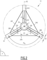
Figure 2 is a schematic upper view of the floating platform of the assembly shown inFigure 1 , and -
Figure 3 is a graphic showing vertical loads applied by swell on the column and on the pontoons of the platform shown inFigures 1 and2 , as a function of the swell period. - An offshore
electricity production assembly 10 according to the invention will be described with reference toFigures 1 and2 . - The
assembly 10 comprises afloating platform 12 floating on a body ofwater 14, a wind turbine 16 (partially represented inFigure 1 ) fixed to the floating platform, andinclined mooring tendons seabed 20. - Advantageously, the
assembly 10 may comprises a first plurality of connectingtendons assembly 10 comprises a second plurality of connectingtendons - The
floating platform 12 comprises a tubularcentral buoyant column 26 extending along a longitudinal axis Z intended to be vertical, and a plurality of tubularradial buoyant pontoons - The
floating platform 12 is subject to a buoyancy force F, thecolumn 26 and thepontoons column 26 and thepontoons - The
column 26 has animmersed portion 30 defining a first average external diameter D1. Each of thepontoons water 14 when themooring tendons - By "average external diameter" of a tubular element, it is meant the external diameter of a cylindrical tube having the same volume.
- The first average external diameter D1 is larger than the second average external diameter D2. Preferably, the ratio D1/D2 is comprised between 1.4 and 2.3.
- For example, the
immersed portion 30 of thecolumn 26 and thepontoons - Advantageously, the
column 26 defines only one or two internal compartment(s) (not shown). - The
column 26 and thewind turbine 16 have a weight W1, and the column, considered alone, is subject to a buoyancy force W2, said buoyancy force W2 being for example comprised between 85% and 115% of said weight W1. - Advantageously, the plurality of
pontoons - For example, each of the
pontoons - Advantageously, the radial axes R1, R2, R3 are regularly spaced around the longitudinal axis Z. Seen from above (
Figure 2 ), the radial axes R1, R2, R3 define angles αN of 360°/N between themselves, N being their number. In the example shown, the angle αN is approximately 120°. - The radial axes R1, R2, R3 also defines an angle β with a transverse plan P perpendicular to the longitudinal axis Z, the angle being comprised between 80° and 100°. For example, the angle β is about 0°, which means that the radial axes R1, R2, R3 are perpendicular to the longitudinal axis Z.
- The transverse plan P for example contains the volumetric center C of the plurality of
pontoons - The floating
platform 12, considered without thewind turbine 16 and themooring tendons water 14 during wet tow to the predefined location of operations on the body ofwater 14 with awater line 32 defining a plan P1 parallel to the transverse plan P. - The plan P1 is advantageously located below the transverse plan P, and for example defines a distance D between them, said distance being smaller than 25% of the second average external diameter D2. This ensures stability of the floating
platform 12 without thewind turbine 16 on it during wet tow. - In the example, there are three
mooring tendons - The mooring tendons 18A, 18B, 18C are tensioned when the
assembly 10 is in operation (position shown inFigure 1 ). - The mooring tendons 18A, 18B, 18C are inclined with respect to the longitudinal axis Z (considered vertical for this matter), and converge upwards. For example, the
mooring tendons platform 12 is balanced without environmental loads (wind, waves, current). These angles may differ from each other and evolve with time, depending on the movements of the floatingplatform 12. InFigure 1 , only the angle γ formed by themooring tendon 18B is represented. - The connecting
tendons column 26 and one of thepontoons tendons pontoon elements column 26. Their function is mainly to reduce the maximum bending moment in thepontons platform 12 is connected to themooring tendons - Any two
successive pontoons tendons - A process for installing the
assembly 10 at a predefined location, according to the invention, will now be described. - First, the floating
platform 12, themooring tendons wind turbine 26 are provided separately (not assembled). - The floating
platform 12 is then moved to the predefined location, the floating platform either floating on the body ofwater 14 and being towed by at least one ship (not shown), or being transported on board a floating vessel (also not shown). If the floatingplatform 12 floats on the body ofwater 14, it does it with a water line 42 corresponding to the plan P1, which provides stability during transportation of the floating platform. - Once the floating
platform 12 is in the predefined location, themooring tendons seabed 20 and to the floating platform, and tensioned. - The
wind turbine 16 is installed onto the floatingplatform 12 using at least one lift or a crane vessel (not shown). - In operation, the
mooring tendons platform 12 is subject to swell conditions. - Swell creates a vertical load on the pontoons (curve C1 in
Figure 3 ) and a vertical load on the column (curve C2) that has an opposite sign. Curve C3 represents the sum VL of these vertical loads. - The curves C1, C2, C3 are calculated using the below example. Vertical loads, in kN/m (kilonewton per meter of wave amplitude), are expressed as a function of the wave period T in seconds. The floating
platform 12 is designed in such way that the vertical load VL (curve C3) is close to zero for a period T1 (so called cancellation period), corresponding to the typical swell peak period encountered in extreme conditions at the location of operations, thus reducing the extreme tension in themooring tendons -
Operating draught H1 28m Wind turbine blade air gap /MSL H2 22m -
Column diameter D1 11.0m Cross section 95.0m2 Buoyancy 2725ton Weight 950ton -
Pontoon length 40m Pontoon diameter D2 6m Cross section 28.3m2 Total buoyancy (x3) 3474ton Total weight (x3) 1018ton -
Total mass considered 1800ton - In the predefined location where the
assembly 10 is, the extreme swell conditions (typically the swell having a 50-years return period) corresponds, for example, to a wave significant height of 12m and a peak period of 16s. - As it can be seen in curve C3, the total vertical load VL is close to zero (at least below 50 kN) for that particular swell peak period. Thanks to the diameter D1 being larger than the diameter D2 and adjusted to the right ratio, the vertical load applied by swell on the
column 26 compensates the vertical load applied by swell on thepontoons mooring tendons - Removing the constraint of the floating platform to be stable in pre-service conditions (i.e. prior to the connection to the mooring tendons) with the wind turbine integrated onto the floating platform allows for further optimization of the design with regards to its volume distribution between the column and the pontoons leading to a reduction of the wave induced excitation force in the vertical axis (i.e. heave excitation force).
- This results in a virtuous circle when designing the floating platform and the mooring tendons reducing the required floating platform volume (and thus its weight) and the extreme tension in the mooring tendons. Indeed, the pre-tension of the mooring tendons shall be high enough to prevent negative tension under extreme environmental conditions. The heave excitation force is one of the main contributors of the mooring tendon dynamic load. Reducing this heave excitation force by optimizing the floating platform design (i.e. its volume distribution) allows for a reduction of the pre-tension, as well as a reduction of the extreme tension in the mooring tendons. The pre-tension being ensured by the buoyancy of the floating platform, the reduced pre-tension allows for further reduction of the floating platform size which in turn reduces the heave excitation force.
- This virtuous circle leads to an optimization of the floating platform and the mooring tendons design. The assembly is thus less expensive to produce.
Claims (15)
- An offshore electricity production assembly (10) comprising a floating platform (12), a wind turbine (16) fixed to the floating platform (12), and inclined mooring tendons (18A, 18B, 18C) connecting the floating platform (12) to a seabed (20), the floating platform (12) comprising:- a tubular central buoyant column (26) extending along a longitudinal axis (Z) intended to be vertical, the column (26) having an immersed portion (30) defining a first average external diameter (D1), and- a plurality of tubular radial buoyant pontoons (28A; 28B, 28C) protruding from the column (26) along radial axes (R1, R2, R3) spaced around the longitudinal axis (Z), each of the pontoons (28A; 28B, 28C) defining a second average external diameter (D2), the pontoons (28A; 28B, 28C) being immersed in a body of water (14),wherein the first average external diameter (D1) is larger than the second average external diameter (D2).
- The electricity production assembly (10) according to claim 1, wherein the first average external diameter (D1) divided by the second average external diameter (D2) is comprised between 1.4 and 2.3.
- The electricity production assembly (10) according to claim 1 or 2, wherein the immersed portion (30) of the column (26) and the pontoons (28A; 28B, 28C) have constant cross-section external diameters along the longitudinal axis (Z) and the radial axes (R1, R2, R3) respectively.
- The electricity production assembly (10) according to any one of claims 1 to 3, wherein the column (26) defines only one or two internal compartment(s).
- The electricity production assembly (10) according to any one of claims 1 to 4, wherein each of the pontoons (28A; 28B, 28C) defines only one internal compartment.
- The electricity production assembly (10) according to any one of claims 1 to 5, wherein the floating platform (12) is subject to a buoyancy force (E), the column (26) and the pontoons (28A; 28B, 28C) being configured to provide at least 90% of said buoyancy force (F).
- The electricity production assembly (10) according to any one of claims 1 to 6, wherein the column (26) and the wind turbine have a weight (W1), and the column (26), considered alone, is subject to a buoyancy force (W2), said buoyancy force (W2) being comprised between 85% and 115% of said weight (W1).
- The electricity production assembly (10) according to any one of claims 1 to 7, wherein the plurality of pontoons (28A; 28B, 28C) consists of three to five pontoons (28A; 28B, 28C).
- The electricity production assembly (10) according to any one of claims 1 to 8, wherein the plurality of pontoons (28A; 28B, 28C) consists of three pontoons (28A; 28B, 28C).
- The electricity production assembly (10) according to any one of claims 1 to 9, wherein each of the radial axes (R1, R2, R3) defines an angle (β) with a transverse plan (P) perpendicular to the longitudinal axis (Z), the angle (β) being comprised between 80° and 100°.
- The electricity production assembly (10) according to claim 10, wherein the floating platform (12), considered without the wind turbine and the mooring tendons (18A, 18B, 18C), is configured to float on the body of water (14) with a water line (32) defining a plan (P1) parallel to the transverse plan (P), the plan (P1) being lower than the transverse plan (P), the transverse plan (P) including a volumetric center (C) of the plurality of pontoons (28A; 28B, 28C).
- The electricity production assembly (10) according to any one of claims 1 to 11, further comprising a first plurality of connecting tendons (22A, 22B, 22C) extending between the column (26) and one of the pontoons (28A; 28B, 28C) respectively for applying upward forces (F1, F2, F3) on the pontoons (28A; 28B, 28C).
- The electricity production assembly (10) according to any one of claims 1 to 12, further comprising a second plurality of connecting tendons (24A, 24B, 24C), any two successive pontoons of the plurality of pontoons (28A; 28B, 28C) around the longitudinal axis (Z) being connected to each other by one of said connecting tendons (24A, 24B, 24C) of the second plurality.
- The electricity production assembly (10) according to any one of claims 1 to 13, wherein the radial axes (R1, R2, R3) are regularly spaced around the longitudinal axis (Z).
- A process for installing an electricity production assembly (10) according to any one of claims 1 to 14 in a predefined location, comprising the following steps:- providing the floating platform (12), the mooring tendons (18A, 18B, 18C), and the wind turbine separately,- moving the floating platform (12) to the predefined location, the floating platform (12) either floating on the body of water (14) and being towed by at least one ship, or being transported on board a floating vessel,- connecting the mooring tendons (18A, 18B, 18C) to the seabed (20) and to the floating platform (12), and tensioning the mooring tendons (18A, 18B, 18C), and- fixing the wind turbine to the floating platform (12) using at least one lift from a crane vessel.
Priority Applications (1)
| Application Number | Priority Date | Filing Date | Title |
|---|---|---|---|
| EP25156379.7A EP4527731A3 (en) | 2021-12-28 | 2021-12-28 | Offshore electricity production assembly comprising a floating platform, a wind turbine, and inclined mooring tendons |
Applications Claiming Priority (2)
| Application Number | Priority Date | Filing Date | Title |
|---|---|---|---|
| EP21306948.7A EP4206066B1 (en) | 2021-12-28 | 2021-12-28 | Offshore electricity production assembly comprising a floating platform, a wind turbine, and inclined mooring tendons |
| EP25156379.7A EP4527731A3 (en) | 2021-12-28 | 2021-12-28 | Offshore electricity production assembly comprising a floating platform, a wind turbine, and inclined mooring tendons |
Related Parent Applications (1)
| Application Number | Title | Priority Date | Filing Date |
|---|---|---|---|
| EP21306948.7A Division EP4206066B1 (en) | 2021-12-28 | 2021-12-28 | Offshore electricity production assembly comprising a floating platform, a wind turbine, and inclined mooring tendons |
Publications (2)
| Publication Number | Publication Date |
|---|---|
| EP4527731A2 true EP4527731A2 (en) | 2025-03-26 |
| EP4527731A3 EP4527731A3 (en) | 2025-05-21 |
Family
ID=79831690
Family Applications (3)
| Application Number | Title | Priority Date | Filing Date |
|---|---|---|---|
| EP25156379.7A Pending EP4527731A3 (en) | 2021-12-28 | 2021-12-28 | Offshore electricity production assembly comprising a floating platform, a wind turbine, and inclined mooring tendons |
| EP21306948.7A Active EP4206066B1 (en) | 2021-12-28 | 2021-12-28 | Offshore electricity production assembly comprising a floating platform, a wind turbine, and inclined mooring tendons |
| EP22769304.1A Pending EP4457135A1 (en) | 2021-12-28 | 2022-08-30 | Offshore electricity production assembly comprising a floating platform, a wind turbine, and inclined mooring tendons |
Family Applications After (2)
| Application Number | Title | Priority Date | Filing Date |
|---|---|---|---|
| EP21306948.7A Active EP4206066B1 (en) | 2021-12-28 | 2021-12-28 | Offshore electricity production assembly comprising a floating platform, a wind turbine, and inclined mooring tendons |
| EP22769304.1A Pending EP4457135A1 (en) | 2021-12-28 | 2022-08-30 | Offshore electricity production assembly comprising a floating platform, a wind turbine, and inclined mooring tendons |
Country Status (10)
| Country | Link |
|---|---|
| US (1) | US20250067249A1 (en) |
| EP (3) | EP4527731A3 (en) |
| JP (1) | JP2025500569A (en) |
| KR (1) | KR20240126874A (en) |
| CN (1) | CN118451026A (en) |
| AU (1) | AU2022429972A1 (en) |
| DK (1) | DK4206066T3 (en) |
| ES (1) | ES3025967T3 (en) |
| PT (1) | PT4206066T (en) |
| WO (1) | WO2023126081A1 (en) |
Family Cites Families (11)
| Publication number | Priority date | Publication date | Assignee | Title |
|---|---|---|---|---|
| WO2004061302A2 (en) * | 2003-01-06 | 2004-07-22 | Vestas Wind Systems A/S | Wind turbine with floating foundation |
| US7843099B2 (en) * | 2005-04-25 | 2010-11-30 | William Sheridan Fielder | Hollow generator |
| US8169099B2 (en) * | 2008-08-18 | 2012-05-01 | Samuel Roznitsky | Deep offshore floating wind turbine and method of deep offshore floating wind turbine assembly, transportation, installation and operation |
| WO2012051382A1 (en) * | 2010-10-13 | 2012-04-19 | Houvener Robert C | Hydrokinetic energy transfer device and method |
| FR2999662A1 (en) * | 2012-12-18 | 2014-06-20 | Ifp Energies Now | OFFSHORE WIND TURBINE ON FLAX HOLDER DESAX |
| US9878265B2 (en) * | 2015-06-16 | 2018-01-30 | Glen Truett Hendrix | System for producing fresh water and electricity using cold ocean water in combination with wind power |
| CN106428446A (en) * | 2016-09-30 | 2017-02-22 | 吴植融 | Straight cylinder type floating platform with extended cylinder body |
| CH715604B1 (en) * | 2017-12-15 | 2021-06-30 | Univ Shanghai Maritime | Support structure system for an offshore wind turbine. |
| CN108284923A (en) * | 2018-01-12 | 2018-07-17 | 天津大学 | A kind of hybrid offshore wind farm buoyant foundations partly latent-Spar |
| EP4157704A1 (en) * | 2020-05-29 | 2023-04-05 | F.Lli Righini S.r.l. | Floating structure |
| CN112648149B (en) * | 2021-01-04 | 2022-07-01 | 上海电气风电集团股份有限公司 | Marine formula fan basis and offshore wind turbine that floats |
-
2021
- 2021-12-28 ES ES21306948T patent/ES3025967T3/en active Active
- 2021-12-28 PT PT213069487T patent/PT4206066T/en unknown
- 2021-12-28 DK DK21306948.7T patent/DK4206066T3/en active
- 2021-12-28 EP EP25156379.7A patent/EP4527731A3/en active Pending
- 2021-12-28 EP EP21306948.7A patent/EP4206066B1/en active Active
-
2022
- 2022-08-30 AU AU2022429972A patent/AU2022429972A1/en active Pending
- 2022-08-30 CN CN202280086392.0A patent/CN118451026A/en active Pending
- 2022-08-30 US US18/724,297 patent/US20250067249A1/en active Pending
- 2022-08-30 KR KR1020247025374A patent/KR20240126874A/en active Pending
- 2022-08-30 JP JP2024539263A patent/JP2025500569A/en active Pending
- 2022-08-30 WO PCT/EP2022/074125 patent/WO2023126081A1/en not_active Ceased
- 2022-08-30 EP EP22769304.1A patent/EP4457135A1/en active Pending
Also Published As
| Publication number | Publication date |
|---|---|
| ES3025967T3 (en) | 2025-06-10 |
| EP4206066A1 (en) | 2023-07-05 |
| EP4457135A1 (en) | 2024-11-06 |
| US20250067249A1 (en) | 2025-02-27 |
| DK4206066T3 (en) | 2025-03-31 |
| EP4206066B1 (en) | 2025-02-12 |
| WO2023126081A1 (en) | 2023-07-06 |
| PT4206066T (en) | 2025-04-16 |
| EP4527731A3 (en) | 2025-05-21 |
| KR20240126874A (en) | 2024-08-21 |
| AU2022429972A1 (en) | 2024-07-04 |
| JP2025500569A (en) | 2025-01-09 |
| CN118451026A (en) | 2024-08-06 |
Similar Documents
| Publication | Publication Date | Title |
|---|---|---|
| US20110206466A1 (en) | Tension Leg Platform With Improved Hydrodynamic Performance | |
| US20180170488A1 (en) | Floating structure for wind turbine and method of intalling same | |
| US6488447B1 (en) | Composite buoyancy module | |
| US8267032B2 (en) | Dual column semisubmersible for offshore application | |
| KR20110124219A (en) | Rework and catamaran systems reduce the load on the superstructure and grid of the catamaran system and save steel | |
| US8087849B2 (en) | Battered column tension leg platform | |
| US20250084830A1 (en) | Hull structure for a semi-submersible wind power turbine platform | |
| US6439810B1 (en) | Buoyancy module with pressure gradient walls | |
| EP4206066B1 (en) | Offshore electricity production assembly comprising a floating platform, a wind turbine, and inclined mooring tendons | |
| US20100224114A1 (en) | Semi-Submersible Vessel, Method For Operating A Semi-Submersible Vessel And Method For Manufacturing A Semi-Submersible Vessel | |
| EP1725447B1 (en) | Floating structure | |
| CN116443192A (en) | Hull structure of semi-submersible wind power platform | |
| CN119072435A (en) | Hull structure of a semi-submersible wind power platform | |
| SE545506C2 (en) | Hull structure for a semi-submersible wind power turbine platform | |
| SE2250021A1 (en) | Hull structure for a semi-submersible wind power turbine platform, related loading method and vessel for transportation of said hull structure | |
| Crowle et al. | Port and installation constraints of Tension Leg Platforms (TLP) floating wind turbines | |
| US20100186650A1 (en) | Preloading to reduce loads and save steel on topsides and grillage of catamaran systems | |
| US20070264086A1 (en) | Tendon for tension leg platform | |
| CN118369265A (en) | Structure and method for transporting, installing and maintaining offshore wind turbines | |
| Sharma et al. | Semisubmersible design faces challenges | |
| Jiménez Vicaría | Upscaling of a TLP concrete floating foundation and the challenges for the supply chain under Norwegian offshore wind targets | |
| Rognaas et al. | Mobile Offshore Base Concepts–Hybrid: Concrete Hull and Steel Topsides. |
Legal Events
| Date | Code | Title | Description |
|---|---|---|---|
| PUAI | Public reference made under article 153(3) epc to a published international application that has entered the european phase |
Free format text: ORIGINAL CODE: 0009012 |
|
| STAA | Information on the status of an ep patent application or granted ep patent |
Free format text: STATUS: THE APPLICATION HAS BEEN PUBLISHED |
|
| AC | Divisional application: reference to earlier application |
Ref document number: 4206066 Country of ref document: EP Kind code of ref document: P |
|
| AK | Designated contracting states |
Kind code of ref document: A2 Designated state(s): AL AT BE BG CH CY CZ DE DK EE ES FI FR GB GR HR HU IE IS IT LI LT LU LV MC MK MT NL NO PL PT RO RS SE SI SK SM TR |
|
| REG | Reference to a national code |
Ref country code: DE Ref legal event code: R079 Free format text: PREVIOUS MAIN CLASS: B63B0077100000 Ipc: B63B0021500000 |
|
| PUAL | Search report despatched |
Free format text: ORIGINAL CODE: 0009013 |
|
| AK | Designated contracting states |
Kind code of ref document: A3 Designated state(s): AL AT BE BG CH CY CZ DE DK EE ES FI FR GB GR HR HU IE IS IT LI LT LU LV MC MK MT NL NO PL PT RO RS SE SI SK SM TR |
|
| RIC1 | Information provided on ipc code assigned before grant |
Ipc: B63B 35/44 20060101ALN20250414BHEP Ipc: B63B 1/10 20060101ALI20250414BHEP Ipc: F03D 13/25 20160101ALI20250414BHEP Ipc: B63B 21/50 20060101AFI20250414BHEP |
|
| STAA | Information on the status of an ep patent application or granted ep patent |
Free format text: STATUS: REQUEST FOR EXAMINATION WAS MADE |
|
| STAA | Information on the status of an ep patent application or granted ep patent |
Free format text: STATUS: EXAMINATION IS IN PROGRESS |
|
| 17P | Request for examination filed |
Effective date: 20251110 |
|
| 17Q | First examination report despatched |
Effective date: 20251120 |
|
| RIC1 | Information provided on ipc code assigned before grant |
Ipc: B63B 21/50 20060101AFI20251117BHEP Ipc: F03D 13/25 20160101ALI20251117BHEP Ipc: B63B 1/10 20060101ALI20251117BHEP Ipc: B63B 35/44 20060101ALN20251117BHEP |