EP4527717A1 - Steering apparatus for vehicle - Google Patents
Steering apparatus for vehicle Download PDFInfo
- Publication number
- EP4527717A1 EP4527717A1 EP24169895.0A EP24169895A EP4527717A1 EP 4527717 A1 EP4527717 A1 EP 4527717A1 EP 24169895 A EP24169895 A EP 24169895A EP 4527717 A1 EP4527717 A1 EP 4527717A1
- Authority
- EP
- European Patent Office
- Prior art keywords
- rotation
- contact
- steering apparatus
- rotating
- rotation shaft
- Prior art date
- Legal status (The legal status is an assumption and is not a legal conclusion. Google has not performed a legal analysis and makes no representation as to the accuracy of the status listed.)
- Granted
Links
Images




Classifications
-
- B—PERFORMING OPERATIONS; TRANSPORTING
- B62—LAND VEHICLES FOR TRAVELLING OTHERWISE THAN ON RAILS
- B62D—MOTOR VEHICLES; TRAILERS
- B62D5/00—Power-assisted or power-driven steering
- B62D5/001—Mechanical components or aspects of steer-by-wire systems, not otherwise provided for in this maingroup
-
- B—PERFORMING OPERATIONS; TRANSPORTING
- B62—LAND VEHICLES FOR TRAVELLING OTHERWISE THAN ON RAILS
- B62D—MOTOR VEHICLES; TRAILERS
- B62D5/00—Power-assisted or power-driven steering
- B62D5/001—Mechanical components or aspects of steer-by-wire systems, not otherwise provided for in this maingroup
- B62D5/005—Mechanical components or aspects of steer-by-wire systems, not otherwise provided for in this maingroup means for generating torque on steering wheel or input member, e.g. feedback
- B62D5/006—Mechanical components or aspects of steer-by-wire systems, not otherwise provided for in this maingroup means for generating torque on steering wheel or input member, e.g. feedback power actuated
-
- B—PERFORMING OPERATIONS; TRANSPORTING
- B62—LAND VEHICLES FOR TRAVELLING OTHERWISE THAN ON RAILS
- B62D—MOTOR VEHICLES; TRAILERS
- B62D5/00—Power-assisted or power-driven steering
- B62D5/04—Power-assisted or power-driven steering electrical, e.g. using an electric servo-motor connected to, or forming part of, the steering gear
- B62D5/0403—Power-assisted or power-driven steering electrical, e.g. using an electric servo-motor connected to, or forming part of, the steering gear characterised by constructional features, e.g. common housing for motor and gear box
-
- B—PERFORMING OPERATIONS; TRANSPORTING
- B62—LAND VEHICLES FOR TRAVELLING OTHERWISE THAN ON RAILS
- B62D—MOTOR VEHICLES; TRAILERS
- B62D5/00—Power-assisted or power-driven steering
- B62D5/04—Power-assisted or power-driven steering electrical, e.g. using an electric servo-motor connected to, or forming part of, the steering gear
- B62D5/0457—Power-assisted or power-driven steering electrical, e.g. using an electric servo-motor connected to, or forming part of, the steering gear characterised by control features of the drive means as such
- B62D5/046—Controlling the motor
- B62D5/0469—End-of-stroke control
Definitions
- Exemplary embodiments of the present disclosure relate to a steering apparatus for a vehicle, and more specifically, to a steering apparatus for a vehicle, which can restrict a rotation of a rotation shaft part.
- a steer-by-wire (SBW) system is an electric signal type intelligent steering system that transmits and controls the driver's will to steer using electric signals without a mechanical linkage between a driver's steering wheel and vehicle wheels.
- the SBW system comprises a steering feedback actuator (SFA) which is an actuator that provides reaction force of the steering wheel to the driver and a road wheel actuator (RWA) which an actuator that moves the vehicle wheels by transmitting the driver's steering intention to the wheels.
- SFA steering feedback actuator
- RWA road wheel actuator
- the SFA and the RWA are connected only by wires without a mechanical linkage. Accordingly, the SBW system requires a structure for restricting its rotation direction. In a related art, a lead screw structure is used to restrict the number of revolutions.
- the lead screw structure in a related art has a problem in that it is difficult to manage straightness according to a tolerance for injection molded plastic busing. In addition, there is a problem in that a friction dispersion occurs greatly due to a clearance between a plastic bushing and a nut, and in case of using a steel nut, an impact sound is generated. In addition, as an assembly for square-shaped bushing is needed, housing processing costs increase and additional processes are required.
- Various embodiments are directed to providing a steering apparatus for a vehicle, which can restrict a rotation of a rotation shaft part.
- a steering apparatus for a vehicle may include a housing having a housing body part, and a housing protrusion part that protrudes from an inner side surface of the housing body part, a rotation shaft part rotatably mounted on the housing, a first rotation part mounted on the rotation shaft part and rotated according to a rotation of the rotation shaft part, a second rotation part rotatably mounted on the rotation shaft part and rotated upon contact with the first rotation part, a third rotation part rotatably mounted on the rotation shaft part, rotated upon contact with the second rotation part, and restricted in its rotation when coming into contact with the housing protrusion part, and a bolt part mounted on an end portion of the rotation shaft part and configured to support the third rotation part.
- the first rotation part may include a first rotation body part having a first rotation hollow part that has a hollow shape, the first rotation body part is mounted on the rotation shaft part and rotated according to the rotation of the rotation shaft part and a first rotation protrusion part that protrudes from the first rotation body part toward a side of the second rotation part, and rotates the second rotation part upon contact with the second rotation part while being rotated according to a rotation of the first rotation body part.
- the second rotation part may include a second rotation body part having a second rotation hollow part that has a hollow shape and rotatably mounted on the rotation shaft part, a second rotating one-side protrusion part that protrudes from the second rotation body part toward a side of the first rotation part, and comes into contact with the first rotation part, and a second rotating other-side protrusion part that protrudes from the second rotation body part toward the side of a third rotation part, and comes into contact with the third rotation part.
- the second rotation part may further include a second rotation opposite part that protrude from one surface and another surface of the second rotation body part in which the second rotation hollow part is formed towards the side of the first rotation part and the side of the third rotation part, respectively.
- the second rotation part may further include an elastic part that is mounted on the second rotating one- side protrusion part or the second rotating other-side protrusion part, and configured to be elastically deformable when coming into contact with the first rotation part or the third rotation part.
- the elastic part may have in the shape of an annular shape and configured to wrap around the second rotating one-side protrusion part and the second rotating other-side protrusion part.
- the elastic part may include a first elastic part configured to wrap around the second rotation opposite part, and a second elastic part that is extended from the first elastic part and mounted to be in contact with an outer side surface of the second rotating one-side protrusion part or the second rotating other-side protrusion.
- the third rotation part may include a third rotation body part having a third rotation hollow part that has a hollow shape and mounted on the rotation shaft part, a third rotation protrusion part that protrudes from the third rotation body part toward the second rotation part side, and comes into contact with the second rotation part, and a third rotation stopper part that protrudes from an outer side surface of the third rotation body part, rotates according to the rotation of the rotation part, and be restricted in its rotation when coming into contact with the housing protrusion part.
- the steering apparatus for a vehicle may further include rotation parts that are disposed between the rotation shaft part and the second rotation part, and between the rotation shaft part and the third rotation part to allow the second rotation part and the third rotation part to rotate separately with respect to the rotation shaft part.
- the steering apparatus for a vehicle may further include a tolerance part disposed between the rotation shaft part and the first rotation part.
- the steering apparatus for a vehicle has a structure in which the first rotation part, the second rotation part, and the third rotation part are configured to transmit rotational force while rotating in a rotational direction of the rotation part, so that there may be no clearance therebetween and the occurrence of friction distribution may be minimized.
- the elastic part is mounted on the second rotation part, and the second rotation part is disposed between the first rotation part and the third rotation part such that an NVH (Noise, Vibration, and Harshness) of the vehicle may be reduced by alleviating shock upon contact.
- NVH Noise, Vibration, and Harshness
- FIG. 1 is a partial cutaway perspective view schematically illustrating a steering apparatus for a vehicle according to an embodiment of the present disclosure
- FIG. 2 is a perspective view schematically illustrating the steering apparatus for a vehicle according to an embodiment of the present disclosure
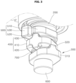
- FIG. 3 is a perspective view schematically illustrating a main structure of the steering apparatus for a vehicle according to an embodiment of the present disclosure
- FIG. 4 is an assembled perspective view schematically illustrating a main structure of the steering apparatus for a vehicle according to an embodiment of the present disclosure.
- FIG. 5 is a partial cutaway view schematically illustrating the steering apparatus for a vehicle according to an embodiment of the present disclosure
- FIG. 6 is a cross-sectional view of FIG. 5 , FIG.
- FIG. 7 is a perspective view schematically illustrating a second rotation part according to an embodiment of the present disclosure
- FIG. 8 is a perspective view schematically illustrating the second rotation part according to another embodiment of the present disclosure
- FIG. 9 is an operational perspective view schematically illustrating a rotation of the rotation shaft part in one direction in the steering apparatus for a vehicle according to an embodiment of the present disclosure
- FIG. 10 is an operational perspective view schematically illustrating a rotation of the rotation shaft part in another direction in the steering apparatus for a vehicle according to an embodiment of the present disclosure.
- a steering apparatus 1 for a vehicle may include a housing 100, a rotation shaft part 200, a first rotation part 300, a second rotation part 400, a third rotation part 500, and a bolt part 600.
- the housing 100 may include a housing body part 110 and a housing protrusion part 120.
- the housing body part 110 may include the first rotation part 300, the second rotation part 400, the third rotation part 500, and the bolt part 600 in an internal space thereof.
- a housing protrusion part 120 may be formed on an inner side surface of the housing body part 110 in a way to protrude therefrom.
- the housing protrusion part 120 may be disposed on a rotation path of the third rotation part 500 on the inner side surface of the housing body part 110.
- the rotation shaft part 200 may be rotatably mounted on the housing body part 110 of the housing 100.
- the rotation shaft part 200 is connected to a shaft of a worm wheel 900 mounted in the steering apparatus 1 for a vehicle and may be rotated along with the shaft along the rotation of the shaft of the worm wheel 900.
- the rotation shaft part 200 is engaged with the shaft of the worm wheel 900 and may be rotated along with the shaft along the rotation of the worm wheel 900.
- the first rotation part 300, the second rotation part 400, and the third rotation part 500 may be mounted on an outer side surface of the rotation shaft part 200. Referring to FIG. 3 , the first rotation part 300, the second rotation part 400, and the third rotation part 500 may be mounted on the outer side surface of the rotation shaft part 200 along a longitudinal direction of the rotation shaft part 200 from bottom to top.
- An accommodating part 210 formed in an angular shape may be formed on the outer side surface of the end portion (the lower end portion with respect to FIG. 3 ) of the rotation shaft part 200.
- the first rotation part 300 which is formed in a planar shape and the like, on the outer side surface of the rotation shaft 200 and is mounted on the rotation shaft part 200 may be mounted on the accommodating part 210.
- the first rotation part 300 may be pressed in and coupled with the accommodating part 210 of the rotation shaft part 200.
- the rotation shaft part 200 may be rotated along with the first rotation part 300.
- the bolt part 600 may be mounted on an end portion (the lower end portion with respect to FIG. 3 ) of the rotation shaft part 200.
- the bolt part 600 mounted on the end portion of the rotation shaft part 200 may prevent the first rotation part 300 from being detached.
- the first rotation part 300 may be mounted on the rotation shaft part 200 and may be rotated according to the rotation of the rotation shaft part 200.
- the first rotation part 300 is coupled to the accommodating part 210 of the rotation shaft part 200 and may be rotated along with the rotation shaft part 200.
- the first rotation part 300 may include a first rotation body part 310 and a first rotation protrusion part 320.
- the first rotation body portion 310 may be provided with a first rotation hollow part 311 formed in a hollow shape and mounted on the rotation shaft part 200, and may be rotated along the rotation of the rotation shaft part 200.
- the first rotation hollow part 311 is formed to be one-sided (to the right side with respect to FIG. 4 ) of the first rotation body part 310 and may be mounted on the accommodating part 210 of the rotation shaft part 200.
- the first rotation hollow part 311 may be formed in a shape corresponding to an angular shape of the accommodating part 210 of the rotation shaft part 200.
- the first rotation hollow part 311 is formed in the shape corresponding to an angular shape of the accommodating part 210 of the rotation shaft part 200 such that a slip phenomenon may be prevented.
- the first rotation hollow part 310 may be pressed in and coupled with the accommodating part 210 of the rotation shaft part 200.
- the first rotation protrusion part 320 may be formed to protrude from the first rotation body part 310 toward the side of the second rotation part 400 and comes into contact with the second rotation part 400 while being rotated according to a rotation of the first rotation body part 310, so that the first rotation protrusion part 320 may rotate the second rotation part 400.
- the first rotation protrusion part 320 may come into contact with the second rotating one-side protrusion part 420 of the second rotation part 400 during its rotation, thereby rotating the first rotation protrusion part 320.
- the second rotation part 400 may be rotatably mounted on the rotation shaft part 200 and may be rotated in contact with the first rotation part 300.
- the second rotation part 400 may be rotated in contact with the first rotation part 300 and may come into contact with the third rotating portion 500.
- the second rotation part 400 may be disposed to be spaced apart from the first rotation part 300.
- the second rotation part 400 may include a second rotation body portion 410, a second rotating one-side protrusion part 420, and a second rotating other-side protrusion part 430.
- the second rotating body portion 410 may be provided with a second rotation hollow part 411 formed in a hollow shape and rotatably mounted on the rotation shaft part 200.
- the second rotation hollow part 411 is formed to be one-sided (to the right side with respect to FIG. 4 ) of the second rotation body part 410 and may be rotatably mounted on the rotation shaft part 200.
- a rotation portion 700 may be mounted on the inner side of the second rotation hollow part 411.
- the second rotating one-side protrusion part 420 may protrude from the second rotation body part 410 toward the side of the first rotation part 300 (toward the lower side with respect to FIG. 4 ) and may come into contact with the first rotation part 300.
- the second rotating one-side protrusion part 420 may be rotated in a rotational direction of the first rotation part 320 in contact with the first rotation protrusion part 320 of the first rotation part 300.
- the second rotation part 400 may be rotated due to a rotation of the second rotating one-side protrusion part 420.
- the second rotating other-side protrusion part 430 may protrude on the second rotation body part 410 toward the side of the third rotation portion 500(toward the upper side with respect to FIG. 4 ) and may come into contact with the third rotation part 500.
- the second rotating other-side protrusion part 430 may be rotated in a rotational direction of the second rotating one-side protrusion part 420 that rotates in contact with the first rotation protrusion part 320 of the first rotation part 300.
- the second rotating other-side protrusion 430 while rotating, comes into contact with the third rotation protrusion part 520 of the third rotation part 500 to rotate the third rotating portion 530.
- the second rotation part 400 may further include a second rotation opposite part 440.
- the second rotation opposite part 440 may be formed to protrude toward the sides of the first rotation part 300 and the third rotation part 500 from one surface (the lower side surface with respect to FIG. 4 ) and the other surface (the upper side surface with respect to FIG. 4 ) of the second rotation body part 410 in which the second rotation hollow part 411 is formed, respectively.
- the second rotation opposite parts 440 may be formed on one surface and the other surface of the second rotation body part 410 and on a portion in which the second rotation hollow portion 411 is formed, so that the first rotation body part 310 of the first rotation part 300 and the third rotation body part 510 of the third rotation part 500 may be formed to have a small contact surface.
- the second rotation part 400 may further include an elastic part 450.
- the elastic part 450 may be mounted on the second rotating one-side protrusion part 420 and/or the second rotating other-side protrusion part 430, and may be elastically deformed when the elastic part 450 comes into contact with the first rotation part 300 and/or the third rotation part 500.
- the elastic part 450 may be mounted on the second rotating one-side protrusion part 420 and/or the second rotating other-side protrusion part 430 to reduce an NVH (Noise, Vibration, and Harshness) that are generated when the elastic part 450 comes into contact with the first rotation part 300 and the third rotation part 500.
- NVH Noise, Vibration, and Harshness
- the elastic part 450 may be made of an elastically deformable material that includes rubber, silicone, and the like.
- the elastic part 450 may be formed in an annular shape and wrap around the second rotating one-side protrusion part 420 and the second rotating other-side protrusion part 430.
- the elastic part 450 may be formed as a band type formed in an annular shape and may surround the second rotating one-side protrusion part 420 and the second rotating other-side protrusion part 430 up and down.
- an elastic part 450 may include a first elastic part 451 and a second elastic part 453.
- the first elastic part 451 may be formed in an annular shape and wrap around the second rotation opposite parts 440.
- the first elastic part 451 may be formed in an annular shape and wrap around the second rotation opposite parts 440 that is formed to protrude from each of one side (the lower side surface with respect to FIG. 8 ) and the other side (the upper side surface with respect to FIG. 8 ) of the second rotation body part 410. That is, the first elastic part 451 may comprise two pieces that wrap around the lower and upper sides of the second rotation opposite part 440. Alternatively, the first elastic part 451 may wrap around at least one of the lower and upper sides of the second rotation opposite part 440.
- the second elastic part 453 may be extended from the first elastic part 451 and may be mounted to be in contact with the outer side surface of the second rotating one-side protrusion part 420 and/or the second rotating other-side protrusion part 430.
- the second elastic part 453 may be joined using a bonding method to the outer side surface of the second rotating one-side protrusion part 420 and/or the second rotating other-side protrusion part 430.
- the third rotation part 500 may be rotatably mounted on the rotation shaft part 200 and rotated in contact with the second rotation part 400 and may be restricted in its rotation when it comes into contact with the housing protrusion part 120.
- the third rotation part 500 may be disposed to be spaced apart from the second rotation part 400.
- the third rotation part 500 may include a third rotation body part 510, a third rotation protrusion part 520, and a third rotation stopper part 530.
- the third rotation body part 510 may be provided with a third rotation hollow part 511 formed in a hollow shape and mounted on the rotation shaft part 200.
- the third rotation hollow part 511 maybe formed to be one side (to the right side with respect to FIG. 4 ) of the third rotation body part 410 and may be mounted on the rotation shaft part 200.
- a rotation part 700 may be mounted on the inner side of the third rotation hollow part 511.
- the third rotation protrusion part 520 may protrude from the third rotation body part 510 toward the side of the second rotation part 400 and may come into contact with the second rotation part 300.
- the third rotation protrusion portion 520 may come into contact with the second rotating other-side protrusion part 430 of the second rotation part 400 and may be rotated along a rotational direction of the second rotation part 400.
- the third rotation stopper part 530 may protrude from the outer side surface of the third rotation body part 510 and may be rotated according to the rotation of the third rotation body part 510, and may be restricted in its rotation when it comes into contact with the housing protrusion part 120.
- the third rotation stopper part 530 may be formed on the outer side surface of the third rotation body part 510 to be able to come contact with the housing protrusion part 120 along a circumferential direction of the third rotation body part 510.
- the third rotating stopper portion 530 may be formed extending from the third rotation protrusion portion 520.
- the third rotation stopper part 530 may be restricted in its rotation when coming into contact with the housing protrusion part 120, thereby restricting the rotation shaft part 200 from being rotated more than 360 degrees.
- the housing protrusion part 120 may be formed to protrude from the inner side surface of the housing body part 110 on the rotation path of the third rotation stopper part 530.
- the position of the housing protrusion part 120 may be adjusted along a circumferential direction of the housing body part 110 to restrict a rotational angle of the third rotation stopper part 530.
- the first rotation part 300, the second rotation part 400, and the third rotation part 500 may all be made of a material that includes a steel material.
- the first rotation part 300, the second rotation part 400, and the third rotation part 500 are made of a material that includes a steel material, so that a structure thereof having a high rigidity and high strength may be maintained.
- the rotation shaft part 200 is described as being configured into 3 parts such as the first rotation part 300, the second rotation part 400, and the third rotation part 500.
- the rotation shaft part 200 may be configured to include a plurality of second rotation parts 400 stacked between the first rotation part 300 and the third rotation part 500.
- the bolt part 600 may be mounted on an end portion (the lower end portion with respect to FIG. 4 ) of the rotation shaft part 200 and may support the third rotation portion 500.
- the bolt part 600 may be coupled to the end portion of the rotation shaft part 200 in a longitudinal direction (the up-down direction with respect to FIG. 4 ) of the rotation shaft part 200.
- the bolt part 600 may be formed to have a screw thread on outer surface thereof and may be coupled to the rotation shaft part 200 by a screw coupling method.
- the head portion of the bolt part 600 may be formed to have greater diameter than the inner diameter of the first rotation hollow part 311 of the first rotation part 300 and supports the first rotation body part 310 of the first rotation part 300, so that the head portion of the bolt part 600 may prevent the first rotation part 300 from being detached.
- the steering apparatus 1 for a vehicle may further include a tolerance part 800.
- the tolerance part 800 may be interposed between the rotation shaft part 200 and the first rotation hollow part 311 of the first rotation body part 310.
- the tolerance part 800 may have a hollow cylindrical shape and may be formed by cutting one side thereof.
- the tolerance part 800 may be mounted on an end portion (the lower end portion with respect to FIG. 4 ) of the rotation shaft part 200 and may come into contact with an inner side surface of the first rotation hollow part 311 of the first rotation part 300.
- the tolerance part 800 may be made of a material that includes a metallic material.
- the tolerance part 800 may prevent the first rotation part 300 from being damaged in case that a force greater than a set value is applied to the rotating rotation shaft part 200 and is transmitted to the first rotation body part 310 of the first rotation part 300.
- the steering apparatus 1 for a vehicle may further include the rotation part 700.
- the rotation part 700 may be disposed between the rotation shaft part 200 and the second rotation part 400, and between the rotation shaft part 200 and the third rotation part 500.
- the rotation part 700 may allow the second rotation part 400 and the third rotation part 500 to separately rotate with respect to the rotation shaft part 200.
- the rotation part 700 may separate the rotation shaft part 200 from the second rotation part 400, and the rotation shaft part 200 from the third rotation part 500 from each other.
- the second rotation 400 and the third rotation 500 may rotate separately with respect to the rotation shaft part 200 by the rotation part 700.
- the rotation part 700 is disposed between the rotation shaft part 200 and the second rotation hollow part 411 of the second body part 410, and between the rotation shaft part 200 and the third rotation hollow part 511 of the third rotation body part 510, so that the rotation part 700 may restrict a rotation of the rotation shaft part 200 from being transmitted to the second rotation part 400 or the third rotation part 500.
- the rotation part 700 may prevent the second rotation part 400 and the third rotation part 500 from being rotated along the rotation of the rotation shaft part 200.
- the rotation part 700 may include a rotation body part 710 and the rotation flange part 720.
- the rotation body part 710 may be formed in a hollow cylindrical shape and may be disposed between the rotation shaft part 200 and the second rotation part 400, and between the rotation shaft part 200 and the third rotation part 500, respectively.
- the rotation body part 710 may be disposed between the rotation shaft part 200 and the second rotation hollow part of the second rotation body part 410, and between the rotation shaft part 200 and the third rotation hollow part 511 of the third rotation body part 510, respectively.
- the rotation flange part 720 may be made of a flat plate formed to have greater diameter than the outer diameter of the rotation body part 710 at an end of the rotation body portion 710 (the lower end portion with respect to FIG. 4 ) , and may come into contact with the first rotation body portion 310 of the first rotation part 300, or may come into contact with the second rotation body part 410 of the second rotation part 400 or the second rotation opposite part 440 of the second rotation part 400.
- FIGS. 9 to 10 An operation of the steering apparatus for a vehicle according to the present disclosure may be described with reference to FIGS. 9 to 10 .
- FIG. 9 it is illustrated that the rotation shaft part 200 is rotated in one direction (the counterclockwise direction with respect to FIG. 9 ) in the steering apparatus 1 for a vehicle according to an embodiment of the present disclosure.
- the first rotation part 300 may also be rotated along the rotational direction of the rotation shaft part 200.
- the first rotation protrusion part 320 of the first rotation part 300 may come into contact with the second rotating one-side protrusion part 420 of the second rotation part 400 according to the rotation of the first rotation part 300.
- the second rotation part 400 may also be rotated along the rotational direction of the first rotation part 300 by the second rotating one-side protrusion part 420 that comes into contact with the first rotation protrusion part 320.
- the second rotating other-side protrusion part 430 of the second rotation part 400 may come into contact with the third rotation protrusion part 520 of the third rotation part 500 according to the rotation of the second rotation part 400.
- the third rotation part 500 may also be rotated along the rotational direction of the second rotation part 400 by the third rotation protrusion part 520 that comes into contact with the second rotating other-side protrusion part 430.
- the third rotation stopper part 530 of the third rotation part 500 which rotates according to the rotation of the third rotation part 500 may be restricted in its rotation by coming into contact with the housing protrusion part 120 of the housing 100.
- the third rotation stopper part 530 may be rotated in the counterclockwise direction less than 360 degrees by contacting with the housing protrusion part 120. Therefore, a rotational angle (a steering angle) of the rotation shaft part 200 in the counterclockwise direction may be restricted.
- FIG. 10 it is illustrated that the rotation shaft part 200 is rotated in the other direction (the clockwise direction with respect to FIG. 10 ) in the steering apparatus 1 for a vehicle according to an embodiment of the present disclosure.
- the first rotation part 300 may also be rotated along the rotational direction of the rotation shaft part 200.
- the first rotation protrusion part 320 of the first rotation part 300 may come into contact with the second rotating one-side protrusion part 420 of the second rotation part 500 according to the rotation of the first rotation part 300.
- the second rotation part 400 may also be rotated along the rotational direction of the first rotation part 300 by the second rotating one-side protrusion part 420 that comes into contact with the first rotation protrusion part 320.
- the second rotating other-side protrusion part 430 of the second rotation part 400 may come into contact with the third rotation protrusion part 520 of the third rotation part 500 according to the rotation of the second rotation part 400.
- the third rotation part 500 may also be rotated along the rotational direction of the second rotation part 400 by the third rotation protrusion part 520 that comes into contact with the second rotating other-side protrusion part 430.
- the third rotation stopper part 530 of the third rotation part 500 that rotates along the rotation of the third rotation part 500 may be restricted from its rotation by contacting with the housing protrusion part 120 of the housing 100.
- the third rotation stopper part 530 may be rotated in the clockwise direction less than 360 degrees by contacting with the housing protrusion part 120. Therefore, a rotation angle (a steering angle) of the rotation shaft part 200 in the clockwise direction may be restricted.
- the steering apparatus 1 for a vehicle has a structure in which the first rotation part 300, the second rotation part 400, and the third rotation part 500 are configured to transmit rotational force while rotating in a rotational direction of the rotation part 200, so that there may be no clearance therebetween and the occurrence of friction distribution may be minimized.
- the elastic part 450 may be mounted on the second rotation part 400, and the second rotation part 400 may be disposed between the first rotation part 300 and the third rotation part 500 such that an NVH (Noise, Vibration, and Harshness) of the vehicle may be reduced by alleviating shock upon contact.
- NVH Noise, Vibration, and Harshness
- the steering apparatus 1 for a vehicle that may be designed to have an optimal size.
Landscapes
- Engineering & Computer Science (AREA)
- Chemical & Material Sciences (AREA)
- Combustion & Propulsion (AREA)
- Transportation (AREA)
- Mechanical Engineering (AREA)
- Power Steering Mechanism (AREA)
Abstract
Description
- Exemplary embodiments of the present disclosure relate to a steering apparatus for a vehicle, and more specifically, to a steering apparatus for a vehicle, which can restrict a rotation of a rotation shaft part.
- A steer-by-wire (SBW) system is an electric signal type intelligent steering system that transmits and controls the driver's will to steer using electric signals without a mechanical linkage between a driver's steering wheel and vehicle wheels.
- The SBW system comprises a steering feedback actuator (SFA) which is an actuator that provides reaction force of the steering wheel to the driver and a road wheel actuator (RWA) which an actuator that moves the vehicle wheels by transmitting the driver's steering intention to the wheels. The SFA and the RWA are connected only by wires without a mechanical linkage. Accordingly, the SBW system requires a structure for restricting its rotation direction. In a related art, a lead screw structure is used to restrict the number of revolutions.
- The lead screw structure in a related art has a problem in that it is difficult to manage straightness according to a tolerance for injection molded plastic busing. In addition, there is a problem in that a friction dispersion occurs greatly due to a clearance between a plastic bushing and a nut, and in case of using a steel nut, an impact sound is generated. In addition, as an assembly for square-shaped bushing is needed, housing processing costs increase and additional processes are required.
- Meanwhile, when evaluating friction at an extremely low temperature, in case of using a plastic material, it may cause a pinching phenomenon due to shrinkage and increase the friction. In addition, it needs to be set to have high strength due to the increase of stopping torque in steering. Therefore, there is a need to improve this.
- The related art of the present disclosure is disclosed in
Korean Patent Application Publication No. 10-2020-0047871 (published on May 8, 2020 - Various embodiments are directed to providing a steering apparatus for a vehicle, which can restrict a rotation of a rotation shaft part.
- A steering apparatus for a vehicle according to the present disclosure may include a housing having a housing body part, and a housing protrusion part that protrudes from an inner side surface of the housing body part, a rotation shaft part rotatably mounted on the housing, a first rotation part mounted on the rotation shaft part and rotated according to a rotation of the rotation shaft part, a second rotation part rotatably mounted on the rotation shaft part and rotated upon contact with the first rotation part, a third rotation part rotatably mounted on the rotation shaft part, rotated upon contact with the second rotation part, and restricted in its rotation when coming into contact with the housing protrusion part, and a bolt part mounted on an end portion of the rotation shaft part and configured to support the third rotation part.
- In an embodiment, the first rotation part may include a first rotation body part having a first rotation hollow part that has a hollow shape, the first rotation body part is mounted on the rotation shaft part and rotated according to the rotation of the rotation shaft part and a first rotation protrusion part that protrudes from the first rotation body part toward a side of the second rotation part, and rotates the second rotation part upon contact with the second rotation part while being rotated according to a rotation of the first rotation body part.
- In an embodiment, the second rotation part may include a second rotation body part having a second rotation hollow part that has a hollow shape and rotatably mounted on the rotation shaft part, a second rotating one-side protrusion part that protrudes from the second rotation body part toward a side of the first rotation part, and comes into contact with the first rotation part, and a second rotating other-side protrusion part that protrudes from the second rotation body part toward the side of a third rotation part, and comes into contact with the third rotation part.
- In an embodiment, the second rotation part may further include a second rotation opposite part that protrude from one surface and another surface of the second rotation body part in which the second rotation hollow part is formed towards the side of the first rotation part and the side of the third rotation part, respectively.
- In an embodiment, the second rotation part may further include an elastic part that is mounted on the second rotating one- side protrusion part or the second rotating other-side protrusion part, and configured to be elastically deformable when coming into contact with the first rotation part or the third rotation part.
- In an embodiment, the elastic part may have in the shape of an annular shape and configured to wrap around the second rotating one-side protrusion part and the second rotating other-side protrusion part.
- In an embodiment, the elastic part may include a first elastic part configured to wrap around the second rotation opposite part, and a second elastic part that is extended from the first elastic part and mounted to be in contact with an outer side surface of the second rotating one-side protrusion part or the second rotating other-side protrusion.
- In an embodiment, the third rotation part may include a third rotation body part having a third rotation hollow part that has a hollow shape and mounted on the rotation shaft part, a third rotation protrusion part that protrudes from the third rotation body part toward the second rotation part side, and comes into contact with the second rotation part, and a third rotation stopper part that protrudes from an outer side surface of the third rotation body part, rotates according to the rotation of the rotation part, and be restricted in its rotation when coming into contact with the housing protrusion part.
- In an embodiment, the steering apparatus for a vehicle may further include rotation parts that are disposed between the rotation shaft part and the second rotation part, and between the rotation shaft part and the third rotation part to allow the second rotation part and the third rotation part to rotate separately with respect to the rotation shaft part.
- In an embodiment, the steering apparatus for a vehicle may further include a tolerance part disposed between the rotation shaft part and the first rotation part.
- According to the steering apparatus for a vehicle in accordance with the present disclosure, the steering apparatus for a vehicle has a structure in which the first rotation part, the second rotation part, and the third rotation part are configured to transmit rotational force while rotating in a rotational direction of the rotation part, so that there may be no clearance therebetween and the occurrence of friction distribution may be minimized.
- Furthermore, according to the present disclosure, the elastic part is mounted on the second rotation part, and the second rotation part is disposed between the first rotation part and the third rotation part such that an NVH (Noise, Vibration, and Harshness) of the vehicle may be reduced by alleviating shock upon contact.
- Furthermore, according to the present disclosure, it is possible to provide a steering apparatus for a vehicle that may be designed to have an optimal size.
-
-
FIG. 1 is a partial cutaway perspective view schematically illustrating a steering apparatus for a vehicle according to an embodiment of the present disclosure. -
FIG. 2 is a perspective view schematically illustrating the steering apparatus for a vehicle according to an embodiment of the present disclosure. -
FIG. 3 is a perspective view schematically illustrating a main structure of the steering apparatus for a vehicle according to an embodiment of the present disclosure. -
FIG. 4 is an assembled perspective view schematically illustrating a main structure of the steering apparatus for a vehicle according to an embodiment of the present disclosure. -
FIG. 5 is a partial cutaway view schematically illustrating the steering apparatus for a vehicle according to an embodiment of the present disclosure. -
FIG. 6 is a cross-sectional view ofFIG. 5 . -
FIG. 7 is a perspective view schematically illustrating a second rotation part according to an embodiment of the present disclosure. -
FIG. 8 is a perspective view schematically illustrating the second rotation part according to another embodiment of the present disclosure. -
FIG. 9 is an operational perspective view schematically illustrating a rotation of the rotation shaft part in one direction in the steering apparatus for a vehicle according to an embodiment of the present disclosure. -
FIG. 10 is an operational perspective view schematically illustrating a rotation of the rotation shaft part in another direction in the steering apparatus for a vehicle according to an embodiment of the present disclosure. - Hereinafter, a steering apparatus for a vehicle according to embodiments of the present disclosure will be described with reference to the accompanying drawings. In this process, the thicknesses of lines or the sizes of components illustrated in the drawings may have been exaggerated for the clarity of a description and for convenience' sake.
- Furthermore, terms to be described below have been defined by taking into consideration their functions in the present disclosure, and may be changed depending on a user or operator's intention or practice. Accordingly, such terms should be defined based on the overall contents of this specification.
-
FIG. 1 is a partial cutaway perspective view schematically illustrating a steering apparatus for a vehicle according to an embodiment of the present disclosure,FIG. 2 is a perspective view schematically illustrating the steering apparatus for a vehicle according to an embodiment of the present disclosure,FIG. 3 is a perspective view schematically illustrating a main structure of the steering apparatus for a vehicle according to an embodiment of the present disclosure,FIG. 4 is an assembled perspective view schematically illustrating a main structure of the steering apparatus for a vehicle according to an embodiment of the present disclosure.FIG. 5 is a partial cutaway view schematically illustrating the steering apparatus for a vehicle according to an embodiment of the present disclosure,FIG. 6 is a cross-sectional view ofFIG. 5 ,FIG. 7 is a perspective view schematically illustrating a second rotation part according to an embodiment of the present disclosure,FIG. 8 is a perspective view schematically illustrating the second rotation part according to another embodiment of the present disclosure,FIG. 9 is an operational perspective view schematically illustrating a rotation of the rotation shaft part in one direction in the steering apparatus for a vehicle according to an embodiment of the present disclosure., andFIG. 10 is an operational perspective view schematically illustrating a rotation of the rotation shaft part in another direction in the steering apparatus for a vehicle according to an embodiment of the present disclosure. - Referring to
FIGS. 1 to 10 , asteering apparatus 1 for a vehicle according to an embodiment of the present disclosure may include ahousing 100, arotation shaft part 200, afirst rotation part 300, asecond rotation part 400, athird rotation part 500, and abolt part 600. - The
housing 100 may include ahousing body part 110 and ahousing protrusion part 120. Thehousing body part 110 may include thefirst rotation part 300, thesecond rotation part 400, thethird rotation part 500, and thebolt part 600 in an internal space thereof. - A
housing protrusion part 120 may be formed on an inner side surface of thehousing body part 110 in a way to protrude therefrom. Thehousing protrusion part 120 may be disposed on a rotation path of thethird rotation part 500 on the inner side surface of thehousing body part 110. - The
rotation shaft part 200 may be rotatably mounted on thehousing body part 110 of thehousing 100. Therotation shaft part 200 is connected to a shaft of aworm wheel 900 mounted in thesteering apparatus 1 for a vehicle and may be rotated along with the shaft along the rotation of the shaft of theworm wheel 900. - The
rotation shaft part 200 is engaged with the shaft of theworm wheel 900 and may be rotated along with the shaft along the rotation of theworm wheel 900. - The
first rotation part 300, thesecond rotation part 400, and thethird rotation part 500 may be mounted on an outer side surface of therotation shaft part 200. Referring toFIG. 3 , thefirst rotation part 300, thesecond rotation part 400, and thethird rotation part 500 may be mounted on the outer side surface of therotation shaft part 200 along a longitudinal direction of therotation shaft part 200 from bottom to top. - An
accommodating part 210 formed in an angular shape may be formed on the outer side surface of the end portion (the lower end portion with respect toFIG. 3 ) of therotation shaft part 200. Thefirst rotation part 300, which is formed in a planar shape and the like, on the outer side surface of therotation shaft 200 and is mounted on therotation shaft part 200 may be mounted on theaccommodating part 210. - The
first rotation part 300 may be pressed in and coupled with theaccommodating part 210 of therotation shaft part 200. Therotation shaft part 200 may be rotated along with thefirst rotation part 300. - The
bolt part 600 may be mounted on an end portion (the lower end portion with respect toFIG. 3 ) of therotation shaft part 200. Thebolt part 600 mounted on the end portion of therotation shaft part 200 may prevent thefirst rotation part 300 from being detached. - The
first rotation part 300 may be mounted on therotation shaft part 200 and may be rotated according to the rotation of therotation shaft part 200. Thefirst rotation part 300 is coupled to theaccommodating part 210 of therotation shaft part 200 and may be rotated along with therotation shaft part 200. - The
first rotation part 300 may include a firstrotation body part 310 and a firstrotation protrusion part 320. The firstrotation body portion 310 may be provided with a first rotationhollow part 311 formed in a hollow shape and mounted on therotation shaft part 200, and may be rotated along the rotation of therotation shaft part 200. - The first rotation
hollow part 311 is formed to be one-sided (to the right side with respect toFIG. 4 ) of the firstrotation body part 310 and may be mounted on theaccommodating part 210 of therotation shaft part 200. The first rotationhollow part 311 may be formed in a shape corresponding to an angular shape of theaccommodating part 210 of therotation shaft part 200. The first rotationhollow part 311 is formed in the shape corresponding to an angular shape of theaccommodating part 210 of therotation shaft part 200 such that a slip phenomenon may be prevented. The first rotationhollow part 310 may be pressed in and coupled with theaccommodating part 210 of therotation shaft part 200. - The first
rotation protrusion part 320 may be formed to protrude from the firstrotation body part 310 toward the side of thesecond rotation part 400 and comes into contact with thesecond rotation part 400 while being rotated according to a rotation of the firstrotation body part 310, so that the firstrotation protrusion part 320 may rotate thesecond rotation part 400. - The first
rotation protrusion part 320 may come into contact with the second rotating one-side protrusion part 420 of thesecond rotation part 400 during its rotation, thereby rotating the firstrotation protrusion part 320. - The
second rotation part 400 may be rotatably mounted on therotation shaft part 200 and may be rotated in contact with thefirst rotation part 300. Thesecond rotation part 400 may be rotated in contact with thefirst rotation part 300 and may come into contact with the thirdrotating portion 500. Thesecond rotation part 400 may be disposed to be spaced apart from thefirst rotation part 300. - The
second rotation part 400 may include a secondrotation body portion 410, a second rotating one-side protrusion part 420, and a second rotating other-side protrusion part 430. The secondrotating body portion 410 may be provided with a second rotationhollow part 411 formed in a hollow shape and rotatably mounted on therotation shaft part 200. - The second rotation
hollow part 411 is formed to be one-sided (to the right side with respect toFIG. 4 ) of the secondrotation body part 410 and may be rotatably mounted on therotation shaft part 200. Arotation portion 700 may be mounted on the inner side of the second rotationhollow part 411. - The second rotating one-
side protrusion part 420 may protrude from the secondrotation body part 410 toward the side of the first rotation part 300 (toward the lower side with respect toFIG. 4 ) and may come into contact with thefirst rotation part 300. The second rotating one-side protrusion part 420 may be rotated in a rotational direction of thefirst rotation part 320 in contact with the firstrotation protrusion part 320 of thefirst rotation part 300. Thesecond rotation part 400 may be rotated due to a rotation of the second rotating one-side protrusion part 420. - The second rotating other-
side protrusion part 430 may protrude on the secondrotation body part 410 toward the side of the third rotation portion 500(toward the upper side with respect toFIG. 4 ) and may come into contact with thethird rotation part 500. The second rotating other-side protrusion part 430 may be rotated in a rotational direction of the second rotating one-side protrusion part 420 that rotates in contact with the firstrotation protrusion part 320 of thefirst rotation part 300. The second rotating other-side protrusion 430 while rotating, comes into contact with the thirdrotation protrusion part 520 of thethird rotation part 500 to rotate the thirdrotating portion 530. - The
second rotation part 400 may further include a second rotation oppositepart 440. The second rotation oppositepart 440 may be formed to protrude toward the sides of thefirst rotation part 300 and thethird rotation part 500 from one surface (the lower side surface with respect toFIG. 4 ) and the other surface (the upper side surface with respect toFIG. 4 ) of the secondrotation body part 410 in which the second rotationhollow part 411 is formed, respectively. The second rotation oppositeparts 440 may be formed on one surface and the other surface of the secondrotation body part 410 and on a portion in which the second rotationhollow portion 411 is formed, so that the firstrotation body part 310 of thefirst rotation part 300 and the thirdrotation body part 510 of thethird rotation part 500 may be formed to have a small contact surface. - The
second rotation part 400 may further include anelastic part 450. Theelastic part 450 may be mounted on the second rotating one-side protrusion part 420 and/or the second rotating other-side protrusion part 430, and may be elastically deformed when theelastic part 450 comes into contact with thefirst rotation part 300 and/or thethird rotation part 500. Theelastic part 450 may be mounted on the second rotating one-side protrusion part 420 and/or the second rotating other-side protrusion part 430 to reduce an NVH (Noise, Vibration, and Harshness) that are generated when theelastic part 450 comes into contact with thefirst rotation part 300 and thethird rotation part 500. - The
elastic part 450 may be made of an elastically deformable material that includes rubber, silicone, and the like. - Referring to
FIG. 7 , in one embodiment of the present disclosure, theelastic part 450 may be formed in an annular shape and wrap around the second rotating one-side protrusion part 420 and the second rotating other-side protrusion part 430. Theelastic part 450 may be formed as a band type formed in an annular shape and may surround the second rotating one-side protrusion part 420 and the second rotating other-side protrusion part 430 up and down. - Referring to
FIG. 8 , in another embodiment of the present disclosure, anelastic part 450 may include a firstelastic part 451 and a secondelastic part 453. The firstelastic part 451 may be formed in an annular shape and wrap around the second rotation oppositeparts 440. The firstelastic part 451 may be formed in an annular shape and wrap around the second rotation oppositeparts 440 that is formed to protrude from each of one side (the lower side surface with respect toFIG. 8 ) and the other side (the upper side surface with respect toFIG. 8 ) of the secondrotation body part 410. That is, the firstelastic part 451 may comprise two pieces that wrap around the lower and upper sides of the second rotation oppositepart 440. Alternatively, the firstelastic part 451 may wrap around at least one of the lower and upper sides of the second rotation oppositepart 440. - The second
elastic part 453 may be extended from the firstelastic part 451 and may be mounted to be in contact with the outer side surface of the second rotating one-side protrusion part 420 and/or the second rotating other-side protrusion part 430. The secondelastic part 453 may be joined using a bonding method to the outer side surface of the second rotating one-side protrusion part 420 and/or the second rotating other-side protrusion part 430. - The
third rotation part 500 may be rotatably mounted on therotation shaft part 200 and rotated in contact with thesecond rotation part 400 and may be restricted in its rotation when it comes into contact with thehousing protrusion part 120. Thethird rotation part 500 may be disposed to be spaced apart from thesecond rotation part 400. - The
third rotation part 500 may include a thirdrotation body part 510, a thirdrotation protrusion part 520, and a thirdrotation stopper part 530. The thirdrotation body part 510 may be provided with a third rotationhollow part 511 formed in a hollow shape and mounted on therotation shaft part 200. - The third rotation
hollow part 511 maybe formed to be one side (to the right side with respect toFIG. 4 ) of the thirdrotation body part 410 and may be mounted on therotation shaft part 200. Arotation part 700 may be mounted on the inner side of the third rotationhollow part 511. - The third
rotation protrusion part 520 may protrude from the thirdrotation body part 510 toward the side of thesecond rotation part 400 and may come into contact with thesecond rotation part 300. The thirdrotation protrusion portion 520 may come into contact with the second rotating other-side protrusion part 430 of thesecond rotation part 400 and may be rotated along a rotational direction of thesecond rotation part 400. - The third
rotation stopper part 530 may protrude from the outer side surface of the thirdrotation body part 510 and may be rotated according to the rotation of the thirdrotation body part 510, and may be restricted in its rotation when it comes into contact with thehousing protrusion part 120. The thirdrotation stopper part 530 may be formed on the outer side surface of the thirdrotation body part 510 to be able to come contact with thehousing protrusion part 120 along a circumferential direction of the thirdrotation body part 510. The thirdrotating stopper portion 530 may be formed extending from the thirdrotation protrusion portion 520. - The third
rotation stopper part 530 may be restricted in its rotation when coming into contact with thehousing protrusion part 120, thereby restricting therotation shaft part 200 from being rotated more than 360 degrees. - The
housing protrusion part 120 may be formed to protrude from the inner side surface of thehousing body part 110 on the rotation path of the thirdrotation stopper part 530. The position of thehousing protrusion part 120 may be adjusted along a circumferential direction of thehousing body part 110 to restrict a rotational angle of the thirdrotation stopper part 530. - The
first rotation part 300, thesecond rotation part 400, and thethird rotation part 500 may all be made of a material that includes a steel material. Thefirst rotation part 300, thesecond rotation part 400, and thethird rotation part 500 are made of a material that includes a steel material, so that a structure thereof having a high rigidity and high strength may be maintained. - In the present disclosure, the
rotation shaft part 200 is described as being configured into 3 parts such as thefirst rotation part 300, thesecond rotation part 400, and thethird rotation part 500. However, therotation shaft part 200 may be configured to include a plurality ofsecond rotation parts 400 stacked between thefirst rotation part 300 and thethird rotation part 500. - The
bolt part 600 may be mounted on an end portion (the lower end portion with respect toFIG. 4 ) of therotation shaft part 200 and may support thethird rotation portion 500. Thebolt part 600 may be coupled to the end portion of therotation shaft part 200 in a longitudinal direction (the up-down direction with respect toFIG. 4 ) of therotation shaft part 200. Thebolt part 600 may be formed to have a screw thread on outer surface thereof and may be coupled to therotation shaft part 200 by a screw coupling method. The head portion of thebolt part 600 may be formed to have greater diameter than the inner diameter of the first rotationhollow part 311 of thefirst rotation part 300 and supports the firstrotation body part 310 of thefirst rotation part 300, so that the head portion of thebolt part 600 may prevent thefirst rotation part 300 from being detached. - The
steering apparatus 1 for a vehicle according to the present disclosure may further include atolerance part 800. Thetolerance part 800 may be interposed between therotation shaft part 200 and the first rotationhollow part 311 of the firstrotation body part 310. - The
tolerance part 800 may have a hollow cylindrical shape and may be formed by cutting one side thereof. Thetolerance part 800 may be mounted on an end portion (the lower end portion with respect toFIG. 4 ) of therotation shaft part 200 and may come into contact with an inner side surface of the first rotationhollow part 311 of thefirst rotation part 300. Thetolerance part 800 may be made of a material that includes a metallic material. - The
tolerance part 800 may prevent thefirst rotation part 300 from being damaged in case that a force greater than a set value is applied to the rotatingrotation shaft part 200 and is transmitted to the firstrotation body part 310 of thefirst rotation part 300. - The
steering apparatus 1 for a vehicle according to the present disclosure may further include therotation part 700. Therotation part 700 may be disposed between therotation shaft part 200 and thesecond rotation part 400, and between therotation shaft part 200 and thethird rotation part 500. Therotation part 700 may allow thesecond rotation part 400 and thethird rotation part 500 to separately rotate with respect to therotation shaft part 200. - The
rotation part 700 may separate therotation shaft part 200 from thesecond rotation part 400, and therotation shaft part 200 from thethird rotation part 500 from each other. Thesecond rotation 400 and thethird rotation 500 may rotate separately with respect to therotation shaft part 200 by therotation part 700. - That is, the
rotation part 700 is disposed between therotation shaft part 200 and the second rotationhollow part 411 of thesecond body part 410, and between therotation shaft part 200 and the third rotationhollow part 511 of the thirdrotation body part 510, so that therotation part 700 may restrict a rotation of therotation shaft part 200 from being transmitted to thesecond rotation part 400 or thethird rotation part 500. Therotation part 700 may prevent thesecond rotation part 400 and thethird rotation part 500 from being rotated along the rotation of therotation shaft part 200. - The
rotation part 700 may include arotation body part 710 and therotation flange part 720. Therotation body part 710 may be formed in a hollow cylindrical shape and may be disposed between therotation shaft part 200 and thesecond rotation part 400, and between therotation shaft part 200 and thethird rotation part 500, respectively. Therotation body part 710 may be disposed between therotation shaft part 200 and the second rotation hollow part of the secondrotation body part 410, and between therotation shaft part 200 and the third rotationhollow part 511 of the thirdrotation body part 510, respectively. - The rotation flange
part 720 may be made of a flat plate formed to have greater diameter than the outer diameter of therotation body part 710 at an end of the rotation body portion 710 (the lower end portion with respect toFIG. 4 ) , and may come into contact with the firstrotation body portion 310 of thefirst rotation part 300, or may come into contact with the secondrotation body part 410 of thesecond rotation part 400 or the second rotation oppositepart 440 of thesecond rotation part 400. - An operation of the steering apparatus for a vehicle according to the present disclosure may be described with reference to
FIGS. 9 to 10 . - Referring to
FIG. 9 , it is illustrated that therotation shaft part 200 is rotated in one direction (the counterclockwise direction with respect toFIG. 9 ) in thesteering apparatus 1 for a vehicle according to an embodiment of the present disclosure. - When the
rotation shaft part 200 is rotated in one direction (the counterclockwise direction with respect toFIG. 9 ) within thehousing 100, thefirst rotation part 300 may also be rotated along the rotational direction of therotation shaft part 200. - The first
rotation protrusion part 320 of thefirst rotation part 300 may come into contact with the second rotating one-side protrusion part 420 of thesecond rotation part 400 according to the rotation of thefirst rotation part 300. Thesecond rotation part 400 may also be rotated along the rotational direction of thefirst rotation part 300 by the second rotating one-side protrusion part 420 that comes into contact with the firstrotation protrusion part 320. - The second rotating other-
side protrusion part 430 of thesecond rotation part 400 may come into contact with the thirdrotation protrusion part 520 of thethird rotation part 500 according to the rotation of thesecond rotation part 400. Thethird rotation part 500 may also be rotated along the rotational direction of thesecond rotation part 400 by the thirdrotation protrusion part 520 that comes into contact with the second rotating other-side protrusion part 430. - The third
rotation stopper part 530 of thethird rotation part 500, which rotates according to the rotation of thethird rotation part 500 may be restricted in its rotation by coming into contact with thehousing protrusion part 120 of thehousing 100. The thirdrotation stopper part 530 may be rotated in the counterclockwise direction less than 360 degrees by contacting with thehousing protrusion part 120. Therefore, a rotational angle (a steering angle) of therotation shaft part 200 in the counterclockwise direction may be restricted. - Referring to
FIG. 10 , it is illustrated that therotation shaft part 200 is rotated in the other direction (the clockwise direction with respect toFIG. 10 ) in thesteering apparatus 1 for a vehicle according to an embodiment of the present disclosure. - When the
rotation shaft part 200 is rotated in the other direction (the clockwise direction with respect toFIG. 10 ) within thehousing 100, thefirst rotation part 300 may also be rotated along the rotational direction of therotation shaft part 200. - The first
rotation protrusion part 320 of thefirst rotation part 300 may come into contact with the second rotating one-side protrusion part 420 of thesecond rotation part 500 according to the rotation of thefirst rotation part 300. Thesecond rotation part 400 may also be rotated along the rotational direction of thefirst rotation part 300 by the second rotating one-side protrusion part 420 that comes into contact with the firstrotation protrusion part 320. - The second rotating other-
side protrusion part 430 of thesecond rotation part 400 may come into contact with the thirdrotation protrusion part 520 of thethird rotation part 500 according to the rotation of thesecond rotation part 400. Thethird rotation part 500 may also be rotated along the rotational direction of thesecond rotation part 400 by the thirdrotation protrusion part 520 that comes into contact with the second rotating other-side protrusion part 430. - The third
rotation stopper part 530 of thethird rotation part 500 that rotates along the rotation of thethird rotation part 500 may be restricted from its rotation by contacting with thehousing protrusion part 120 of thehousing 100. The thirdrotation stopper part 530 may be rotated in the clockwise direction less than 360 degrees by contacting with thehousing protrusion part 120. Therefore, a rotation angle (a steering angle) of therotation shaft part 200 in the clockwise direction may be restricted. - According to the
steering apparatus 1 for a vehicle in accordance with the present disclosure, thesteering apparatus 1 for a vehicle has a structure in which thefirst rotation part 300, thesecond rotation part 400, and thethird rotation part 500 are configured to transmit rotational force while rotating in a rotational direction of therotation part 200, so that there may be no clearance therebetween and the occurrence of friction distribution may be minimized. - In addition, according to the present disclosure, the
elastic part 450 may be mounted on thesecond rotation part 400, and thesecond rotation part 400 may be disposed between thefirst rotation part 300 and thethird rotation part 500 such that an NVH (Noise, Vibration, and Harshness) of the vehicle may be reduced by alleviating shock upon contact. - In addition, according to the present disclosure, it may be possible to provide the
steering apparatus 1 for a vehicle that may be designed to have an optimal size. - Although exemplary embodiments of the disclosure have been disclosed for illustrative purposes, those skilled in the art will appreciate that various modifications, additions and substitutions are possible, without departing from the scope and spirit of the disclosure as defined in the accompanying claims. Thus, the true technical scope of the disclosure should be defined by the following claims.
Claims (10)
- A steering apparatus for a vehicle, comprising:a housing having a housing body part, and a housing protrusion part that protrudes from an inner side surface of the housing body part;a rotation shaft part rotatably mounted on the housing;a first rotation part mounted on the rotation shaft part and rotated according to a rotation of the rotation shaft part;a second rotation part rotatably mounted on the rotation shaft part and rotated upon contact with the first rotation part;a third rotation part rotatably mounted on the rotation shaft part, rotated upon contact with the second rotation part, and restricted in its rotation when coming into contact with the housing protrusion part; anda bolt part mounted on an end portion of the rotation shaft part and configured to support the third rotation part.
- The steering apparatus for the vehicle of claim 1, wherein the first rotation part comprises:a first rotation body part having a first rotation hollow part that has a hollow shape, the first rotation body part is mounted on the rotation shaft part, and rotated according to the rotation of the rotation shaft part; anda first rotation protrusion part that protrudes from the first rotation body part toward a side of the second rotation part, and rotates the second rotation part upon contact with the second rotation part while being rotated according to the rotation of the first rotation body part.
- The steering apparatus for the vehicle of claim 1 or 2, wherein the second rotation part comprises:a second rotation body part having a second rotation hollow part that has a hollow shape and rotatably mounted on the rotation shaft part;a second rotating one-side protrusion part that protrudes from the second rotation body part toward a side of the first rotation part, and comes into contact with the first rotation part;a second rotating other-side protrusion part that protrudes from the second rotation body part toward a side of the third rotation part, and comes into contact with the third rotation part.
- The steering apparatus for the vehicle of claim 3, wherein the second rotation part further comprises:
a second rotation opposite part that protrudes from one surface and the other surface of the second rotation body part in which the second rotation hollow part is present, towards the side of the first rotation part and the side of the third rotation part, respectively. - The steering apparatus for the vehicle of claim 4, wherein the second rotation part further comprises:
an elastic part that is mounted on the second rotating one-side protrusion part or the second rotating other-side protrusion part, and configured to be elastically deformable when coming into contact with the first rotation part or the third rotation part. - The steering apparatus for the vehicle of claim 5, wherein the elastic part has a shape of an annular shape and configured to wrap around the second rotating one-side protrusion part and the second rotating other-side protrusion part.
- The steering apparatus for the vehicle of claim 5 or 6, wherein the elastic part comprises:a first elastic part configured to wrap around the second rotation opposite part; anda second elastic part that is extended from the first elastic part and mounted to be in contact with an outer side surface of the second rotating one-side protrusion part or the second rotating other-side protrusion part.
- The steering apparatus for the vehicle of any one of claims 1 to 7, wherein the third rotation part comprises:a third rotation body part having a third rotation hollow part that has a hollow shape and mounted on the rotation shaft part;a third rotation protrusion part that protrudes from the third rotation body part toward the second rotation part, and comes into contact with the second rotation part;a third rotation stopper part that protrudes from an outer side surface of the third rotation body part, rotates according to the rotation of the third rotation body part, and be restricted from its rotation when coming into contact with the housing protrusion part.
- The steering apparatus for the vehicle of any one of claims 1 to 8, further comprising:
rotation parts that are disposed between the rotation shaft part and the second rotation part, and between the rotation shaft part and the third rotation part, respectively, to allow the second rotation part and the third rotation part to rotate separately with respect to the rotation shaft part. - The steering apparatus for the vehicle of any one of claims 1 to 9, further comprising a tolerance part disposed between the rotation shaft part and the first rotation part.
Applications Claiming Priority (1)
| Application Number | Priority Date | Filing Date | Title |
|---|---|---|---|
| KR1020230124609A KR20250041776A (en) | 2023-09-19 | 2023-09-19 | Steering apparatus for vehicle |
Publications (2)
| Publication Number | Publication Date |
|---|---|
| EP4527717A1 true EP4527717A1 (en) | 2025-03-26 |
| EP4527717B1 EP4527717B1 (en) | 2026-04-29 |
Family
ID=90730256
Family Applications (1)
| Application Number | Title | Priority Date | Filing Date |
|---|---|---|---|
| EP24169895.0A Active EP4527717B1 (en) | 2023-09-19 | 2024-04-12 | Steering apparatus for vehicle |
Country Status (4)
| Country | Link |
|---|---|
| US (1) | US20250091637A1 (en) |
| EP (1) | EP4527717B1 (en) |
| KR (1) | KR20250041776A (en) |
| CN (1) | CN119659735A (en) |
Citations (7)
| Publication number | Priority date | Publication date | Assignee | Title |
|---|---|---|---|---|
| JP2000272526A (en) * | 1999-03-26 | 2000-10-03 | Koyo Seiko Co Ltd | Vehicle steering system |
| US8775028B2 (en) * | 2012-03-22 | 2014-07-08 | Jtekt Corporation | Vehicle steering system |
| US20200130725A1 (en) * | 2018-10-30 | 2020-04-30 | Jtekt Corporation | Vehicle steering apparatus |
| KR20200047871A (en) | 2018-10-25 | 2020-05-08 | 현대자동차주식회사 | Apparatus for limitted steering angle in steer-by-wire system |
| US10676126B2 (en) * | 2016-10-14 | 2020-06-09 | Steering Solutions Ip Holding Corporation | Rotation control assembly for a steering column |
| DE102019111992A1 (en) * | 2019-05-08 | 2020-11-12 | Schaeffler Technologies AG & Co. KG | Electromechanical steering arrangement |
| US20220396304A1 (en) * | 2021-06-15 | 2022-12-15 | Zf Automotive Germany Gmbh | Steering device comprising an end stop device and steer-by-wire steering system comprising such a steering device |
-
2023
- 2023-09-19 KR KR1020230124609A patent/KR20250041776A/en active Pending
-
2024
- 2024-04-04 US US18/626,731 patent/US20250091637A1/en active Pending
- 2024-04-12 EP EP24169895.0A patent/EP4527717B1/en active Active
- 2024-08-06 CN CN202411072879.0A patent/CN119659735A/en active Pending
Patent Citations (7)
| Publication number | Priority date | Publication date | Assignee | Title |
|---|---|---|---|---|
| JP2000272526A (en) * | 1999-03-26 | 2000-10-03 | Koyo Seiko Co Ltd | Vehicle steering system |
| US8775028B2 (en) * | 2012-03-22 | 2014-07-08 | Jtekt Corporation | Vehicle steering system |
| US10676126B2 (en) * | 2016-10-14 | 2020-06-09 | Steering Solutions Ip Holding Corporation | Rotation control assembly for a steering column |
| KR20200047871A (en) | 2018-10-25 | 2020-05-08 | 현대자동차주식회사 | Apparatus for limitted steering angle in steer-by-wire system |
| US20200130725A1 (en) * | 2018-10-30 | 2020-04-30 | Jtekt Corporation | Vehicle steering apparatus |
| DE102019111992A1 (en) * | 2019-05-08 | 2020-11-12 | Schaeffler Technologies AG & Co. KG | Electromechanical steering arrangement |
| US20220396304A1 (en) * | 2021-06-15 | 2022-12-15 | Zf Automotive Germany Gmbh | Steering device comprising an end stop device and steer-by-wire steering system comprising such a steering device |
Also Published As
| Publication number | Publication date |
|---|---|
| CN119659735A (en) | 2025-03-21 |
| KR20250041776A (en) | 2025-03-26 |
| EP4527717B1 (en) | 2026-04-29 |
| US20250091637A1 (en) | 2025-03-20 |
Similar Documents
| Publication | Publication Date | Title |
|---|---|---|
| KR100493861B1 (en) | Damper mechanism of steering apparatus | |
| JP5413266B2 (en) | Steering device | |
| KR102331935B1 (en) | Power Transmission Device of Electric Power Steering Apparatus | |
| KR20140120074A (en) | Electric power steering apparatus for vehicle and method of assembling the same | |
| US9718491B2 (en) | Steering apparatus for vehicle | |
| US10781906B2 (en) | Motor-driven power steering system | |
| JP2008120213A (en) | Vehicle steering system | |
| CN111801265B (en) | Steering device | |
| EP4527717B1 (en) | Steering apparatus for vehicle | |
| US8777266B2 (en) | Steering device | |
| US7780176B2 (en) | Center take-off rack-and-pinion steering apparatus | |
| KR101393253B1 (en) | Power Transmission Device of Electric Power Steering Apparatus | |
| KR102944315B1 (en) | Steering angle limiting device and steering apparatus including the same | |
| US9616916B2 (en) | Electric power steering device | |
| US11912333B2 (en) | Steering device | |
| KR20240159304A (en) | Steering apparatus | |
| US20150266502A1 (en) | Steering device | |
| KR100343573B1 (en) | Gear box mounting structure of steering device for automobile | |
| JP5434250B2 (en) | Vehicle steering damper device and steering device | |
| US20230143959A1 (en) | Steering device | |
| KR20240177107A (en) | Steering apparatus | |
| US20140290401A1 (en) | Steering apparatus | |
| KR102767236B1 (en) | Steering feel control apparatus | |
| JPH05170108A (en) | Joint for steering shaft | |
| KR20140141114A (en) | Motor driven power steering |
Legal Events
| Date | Code | Title | Description |
|---|---|---|---|
| PUAI | Public reference made under article 153(3) epc to a published international application that has entered the european phase |
Free format text: ORIGINAL CODE: 0009012 |
|
| STAA | Information on the status of an ep patent application or granted ep patent |
Free format text: STATUS: THE APPLICATION HAS BEEN PUBLISHED |
|
| AK | Designated contracting states |
Kind code of ref document: A1 Designated state(s): AL AT BE BG CH CY CZ DE DK EE ES FI FR GB GR HR HU IE IS IT LI LT LU LV MC ME MK MT NL NO PL PT RO RS SE SI SK SM TR |
|
| STAA | Information on the status of an ep patent application or granted ep patent |
Free format text: STATUS: REQUEST FOR EXAMINATION WAS MADE |
|
| 17P | Request for examination filed |
Effective date: 20250923 |
|
| GRAP | Despatch of communication of intention to grant a patent |
Free format text: ORIGINAL CODE: EPIDOSNIGR1 |
|
| STAA | Information on the status of an ep patent application or granted ep patent |
Free format text: STATUS: GRANT OF PATENT IS INTENDED |
|
| INTG | Intention to grant announced |
Effective date: 20251215 |
|
| P01 | Opt-out of the competence of the unified patent court (upc) registered |
Free format text: CASE NUMBER: UPC_APP_0003194_4527717/2026 Effective date: 20260129 |
|
| GRAS | Grant fee paid |
Free format text: ORIGINAL CODE: EPIDOSNIGR3 |
|
| GRAA | (expected) grant |
Free format text: ORIGINAL CODE: 0009210 |
|
| STAA | Information on the status of an ep patent application or granted ep patent |
Free format text: STATUS: THE PATENT HAS BEEN GRANTED |
|
| AK | Designated contracting states |
Kind code of ref document: B1 Designated state(s): AL AT BE BG CH CY CZ DE DK EE ES FI FR GB GR HR HU IE IS IT LI LT LU LV MC ME MK MT NL NO PL PT RO RS SE SI SK SM TR |
|
| REG | Reference to a national code |
Ref country code: CH Ref legal event code: F10 Free format text: ST27 STATUS EVENT CODE: U-0-0-F10-F00 (AS PROVIDED BY THE NATIONAL OFFICE) Effective date: 20260429 Ref country code: GB Ref legal event code: FG4D |
|
| REG | Reference to a national code |
Ref country code: IE Ref legal event code: FG4D |
|
| REG | Reference to a national code |
Ref country code: DE Ref legal event code: R096 Ref document number: 602024004301 Country of ref document: DE |