EP4527652A1 - Concealed belt molding assembly - Google Patents
Concealed belt molding assembly Download PDFInfo
- Publication number
- EP4527652A1 EP4527652A1 EP23806966.0A EP23806966A EP4527652A1 EP 4527652 A1 EP4527652 A1 EP 4527652A1 EP 23806966 A EP23806966 A EP 23806966A EP 4527652 A1 EP4527652 A1 EP 4527652A1
- Authority
- EP
- European Patent Office
- Prior art keywords
- belt weatherstrip
- injection
- vehicle door
- sheet metal
- joint corner
- Prior art date
- Legal status (The legal status is an assumption and is not a legal conclusion. Google has not performed a legal analysis and makes no representation as to the accuracy of the status listed.)
- Pending
Links
Images
Classifications
-
- B—PERFORMING OPERATIONS; TRANSPORTING
- B60—VEHICLES IN GENERAL
- B60J—WINDOWS, WINDSCREENS, NON-FIXED ROOFS, DOORS, OR SIMILAR DEVICES FOR VEHICLES; REMOVABLE EXTERNAL PROTECTIVE COVERINGS SPECIALLY ADAPTED FOR VEHICLES
- B60J10/00—Sealing arrangements
- B60J10/70—Sealing arrangements specially adapted for windows or windscreens
- B60J10/74—Sealing arrangements specially adapted for windows or windscreens for sliding window panes, e.g. sash guides
- B60J10/76—Sealing arrangements specially adapted for windows or windscreens for sliding window panes, e.g. sash guides for window sashes; for glass run channels
-
- B—PERFORMING OPERATIONS; TRANSPORTING
- B60—VEHICLES IN GENERAL
- B60J—WINDOWS, WINDSCREENS, NON-FIXED ROOFS, DOORS, OR SIMILAR DEVICES FOR VEHICLES; REMOVABLE EXTERNAL PROTECTIVE COVERINGS SPECIALLY ADAPTED FOR VEHICLES
- B60J10/00—Sealing arrangements
- B60J10/20—Sealing arrangements characterised by the shape
- B60J10/26—Sealing arrangements characterised by the shape characterised by the surface shape
- B60J10/265—Sealing arrangements characterised by the shape characterised by the surface shape the surface being primarily decorative
-
- B—PERFORMING OPERATIONS; TRANSPORTING
- B60—VEHICLES IN GENERAL
- B60J—WINDOWS, WINDSCREENS, NON-FIXED ROOFS, DOORS, OR SIMILAR DEVICES FOR VEHICLES; REMOVABLE EXTERNAL PROTECTIVE COVERINGS SPECIALLY ADAPTED FOR VEHICLES
- B60J10/00—Sealing arrangements
- B60J10/30—Sealing arrangements characterised by the fastening means
-
- B—PERFORMING OPERATIONS; TRANSPORTING
- B60—VEHICLES IN GENERAL
- B60J—WINDOWS, WINDSCREENS, NON-FIXED ROOFS, DOORS, OR SIMILAR DEVICES FOR VEHICLES; REMOVABLE EXTERNAL PROTECTIVE COVERINGS SPECIALLY ADAPTED FOR VEHICLES
- B60J10/00—Sealing arrangements
- B60J10/30—Sealing arrangements characterised by the fastening means
- B60J10/36—Sealing arrangements characterised by the fastening means using separately inserted fastening means, e.g. using clips, beads or strips
-
- B—PERFORMING OPERATIONS; TRANSPORTING
- B60—VEHICLES IN GENERAL
- B60J—WINDOWS, WINDSCREENS, NON-FIXED ROOFS, DOORS, OR SIMILAR DEVICES FOR VEHICLES; REMOVABLE EXTERNAL PROTECTIVE COVERINGS SPECIALLY ADAPTED FOR VEHICLES
- B60J10/00—Sealing arrangements
- B60J10/70—Sealing arrangements specially adapted for windows or windscreens
- B60J10/74—Sealing arrangements specially adapted for windows or windscreens for sliding window panes, e.g. sash guides
- B60J10/75—Sealing arrangements specially adapted for windows or windscreens for sliding window panes, e.g. sash guides for sealing the lower part of the panes
-
- B—PERFORMING OPERATIONS; TRANSPORTING
- B60—VEHICLES IN GENERAL
- B60J—WINDOWS, WINDSCREENS, NON-FIXED ROOFS, DOORS, OR SIMILAR DEVICES FOR VEHICLES; REMOVABLE EXTERNAL PROTECTIVE COVERINGS SPECIALLY ADAPTED FOR VEHICLES
- B60J10/00—Sealing arrangements
- B60J10/80—Sealing arrangements specially adapted for opening panels, e.g. doors
- B60J10/86—Sealing arrangements specially adapted for opening panels, e.g. doors arranged on the opening panel
Definitions
- the present utility model relates to the technical field of vehicles and, in particular, to a hidden belt weatherstrip assembly.
- a vehicle door outer belt weatherstrip is a kind of sealing strips, which is assembled between a vehicle door glass and a vehicle door outer plate to achieve effects of decorating and sealing a vehicle door window as well as guiding the running of the vehicle door glass simultaneously, and which is an indispensable part in automobile assembling.
- a hidden outer belt weatherstrip is generally used.
- the outer belt weatherstrip being fixed to a vehicle door sheet metal is achieved by designing the inner belt weatherstrip with an injection-molded joint corner and using a double-sided film for bonding.
- the hidden outer belt weatherstrip has no fixing and fitting style formed at its two ends with the vehicle door sheet metal, hence failing to fully cover ends of the vehicle door sheet metal.
- a hidden belt weatherstrip assembly is provided on a vehicle door sheet metal provided with a first positioning member, and includes an outer belt weatherstrip, where a first injection-molded joint corner is provided on an end side of the outer belt weatherstrip, and a first positioning portion is provided on the first injection-molded joint corner.
- the first injection-molded joint corner is fixed to the vehicle door sheet metal, and the first positioning member is fitted to the first positioning portion.
- the assembly also includes an inner belt weatherstrip, where the inner belt weatherstrip is provided corresponding to the outer belt weatherstrip.
- a second injection-molded joint corner is provided on an end side of the inner belt weatherstrip, the second injection-molded joint corner is fixed to the vehicle door sheet metal, and the second injection-molded joint corner is provided corresponding to the first injection-molded joint corner.
- the first positioning portion is a slot.
- the first positioning member is a positioning column, and the positioning column is provided to protrude towards the outer belt weatherstrip along a sheet metal surface of the vehicle door sheet metal 1.
- the positioning column is in a welded connection with the vehicle door sheet metal.
- first positioning member is closely connected with the injection-molded joint corner of the outer belt weatherstrip.
- first injection-molded joint corner and the first positioning portion are integrally formed by injection molding.
- a second positioning portion is provided on the second injection-molded joint corner
- a second positioning member is provided on the vehicle door sheet metal, and the second positioning member is fitted to the second positioning portion.
- an embodiment of the present application provides a hidden belt weatherstrip assembly, which is provided on a vehicle door sheet metal 1 provided with a first positioning member 111, and includes an outer belt weatherstrip 2, where a first injection-molded joint corner 21 is provided on an end side of the outer belt weatherstrip 2, and a first positioning portion 211 is provided on the first injection-molded joint corner 21; and where the first injection-molded joint corner 21 is fixed to the vehicle door sheet metal 1, and the first positioning member 11 is fitted to the first positioning portion 211.
- the present application takes advantage of a fitted connection between the first positioning portion 211 provided at the outer belt weatherstrip 2 and the first positioning member 11 of the vehicle door sheet metal 1, so that it is convenient to install and position the outer belt weatherstrip 2, and further a hemming area of the vehicle door sheet metal 1 is reasonably covered on the basis of providing the first injection-molded joint corner 21 to the outer belt weatherstrip 2, thereby avoiding a problem of poor appearance caused by hemming of the sheet metal in an irregular area after the vehicle door is opened.
- the hidden belt weatherstrip assembly further includes an inner belt weatherstrip 3, where the inner belt weatherstrip 3 is provided corresponding to the outer belt weatherstrip 2.
- the vehicle door sheet metal 1 is divided into a vehicle door inner plate 12 and a vehicle door outer plate 13, and both the inner belt weatherstrip 3 and the outer belt weatherstrip 2 are fixed to the vehicle door inner plate 12, in particular, both the inner belt weatherstrip 3 and the outer belt weatherstrip 2 can be clamped to the vehicle door interior plate 12.
- the inner belt weatherstrip 3 is located below the outer belt weatherstrip 2 (see a mark A in FIG.
- the inner belt weatherstrip 3 and the outer belt weatherstrip 2 are provided with a lip edge 14 contactable with a vehicle window glass 4, so that water droplets, steams and dusts on the glass surface are cut off when the vehicle window glass 4 is regulated, improving sealing performance between the hidden belt weatherstrip assembly and the vehicle window glass 4, and when in use, the rainwater can be effectively prevented from passing through the hidden belt weatherstrip assembly to reach the inside of the vehicle door exterior plate 13, playing an aesthetic role meanwhile.
- a second injection-molded joint corner 31 is provided on an end side of the inner belt weatherstrip 3, the second injection-molded joint corner 31 is fixed to the vehicle door sheet metal 1, and the second injection-molded joint corner 31 is provided corresponding to the first injection-molded joint corner 21.
- the second injection-molded joint corner 31 is provided on the end side of the inner belt weatherstrip 3, a hemming area of the vehicle door sheet metal 1 can be reasonably covered by the inner belt weatherstrip 3.
- the hemming area of the vehicle door sheet metal 1 can be covered in full jointly by the inner belt weatherstrip 3 and the outer belt weatherstrip 2.
- the first positioning portion 211 is a slot provided on an inner side of the outer belt weatherstrip 2, the slot is an open structure with a notch downwards, and a depth of the slot is less than a thickness of a corresponding position of the outer belt weatherstrip 2, that is, the slot does not run through the outer belt weatherstrip 2 in a thickness direction of the outer belt weatherstrip 2.
- the slot has an accommodating area 211a and an opening 211b in communication with the accommodating area 211a, where the opening 211b of the slot is dimensionally matched with the first positioning member 11, the opening 211b of the slot is also provided with guiding edges 211c extending inclined outwards and downwards from the opening 211b to both sides, and two guiding edges 211c together form a flared shaped structure.
- the opening 211b of the slot is oriented towards the first positioning member 11, and the first positioning member 11 smoothly enters the slot through the guiding edges 211c, facilitating the assembly of the outer belt weatherstrip 2 and the vehicle door sheet metal 1.
- the first positioning member 11 includes a positioning column 111, and the positioning column 111 is provided to protrude towards the outer belt weatherstrip 2 along a sheet metal surface of the vehicle door sheet metal 1.
- the positioning column 111 protrudes and extends inwardly along the vehicle door inner plate 12.
- a limiting block 112 is provided at an end of the positioning column 111, and the limiting block 112 is clamped into the accommodating area 211a after the positioning column 111 passes through the opening 211b of the slot, so that the outer belt weatherstrip 2 is fixed to the vehicle door inner plate 12.
- the first positioning member 11 includes but is not limited to fasteners such as a bolt and a screw. In an embodiment, the first positioning member 11 is a bolt.
- the limiting block is added to the positioning column, so that the accommodating area 211a on the outer belt weatherstrip 2 is clamped to the limiting block 112 of the vehicle door sheet metal 1, thereby limiting the outer belt weatherstrip 2, and improving installation stability of the outer belt weatherstrip 2.
- the positioning column is in a welded connection with the vehicle door sheet metal 1.
- the positioning column is fixed to the vehicle door sheet metal 1 by means of welding, thus an installation reference is provided for the outer belt weatherstrip 2, and the accommodating area 211a on the outer belt weatherstrip 2 is clamped to the limiting block 112 of the vehicle door sheet metal 1 during installation; in addition, the outer surface of the outer belt weatherstrip 2 abuts against the inner surface of the vehicle door sheet metal 1, thereby achieving the limiting of the outer belt weatherstrip 2 in the Y-direction of the vehicle body, and improving service life of the parts.
- the positioning column can also be fixed to the vehicle door sheet metal 1 by means of bonding, clamping or threaded connection.
- the first positioning member 11 is joint with the first injection-molded joint corner 21 on the outer belt weatherstrip 2 in a length direction of a vehicle body by a lap amount of 2.0 mm to 3.0 mm, that is, the positioning column 111 has a diameter of 2.0 mm to 3.0 mm.
- the first injection-molded joint corner 21 on the outer belt weatherstrip 2 in the present embodiment is clamped with a stud welded on the vehicle door sheet metal 1, and the welded stud is unilaterally joint with the first injection-molded joint corner 21 on the outer belt weatherstrip 2 by a lap amount of 2.5 mm in the X-direction, playing a role of X-direction limiting.
- the first positioning member 11 is closely fitted to the first injection-molded joint corner 21 on the outer belt weatherstrip 2.
- the first injection-molded joint corner 21 on the outer belt weatherstrip 2 is clamped with the stud welded on the vehicle door sheet metal 1; the welded stud and the first injection-molded joint corner 21 on the outer belt weatherstrip 2 have a contact clearance of zero in the Z-direction (see a mark B in FIG. 5 for a contact point fitting in the Z-direction), hence playing a role of Z-direction positioning for the outer belt weatherstrip during assembly.
- the first injection-molded joint corner 21 and the first positioning portion 211 are integrally formed by injection molding.
- the integral injection molding can ensure stability of structure of the first injection-molded joint corner 21, so that it is convenient for mass production.
- a second positioning portion is provided on the second injection-molded joint corner 31, a second positioning member is provided on the vehicle door sheet metal 1, and the second positioning member is fitted to the second positioning portion.
- the second positioning portion in order to facilitate the positioning and installation of the inner belt weatherstrip 3, is provided as a slot in terms of its structure, and the second positioning portion is provided as a positioning column in terms of its structure, and a specific arrangement relationship therebetween is the same as the arrangement relationship in the outer belt weatherstrip, hence details will not be described here again.
- the present application in another aspect provides a vehicle door, including the vehicle door sheet metal 1 and the hidden belt weatherstrip assembly as described above.
- an injection-molded joint corner structure is provided on the outer belt weatherstrip, and cooperates with the injection-molded joint corner for the inner belt weatherstrip, to reasonably cover the hemming area of the vehicle door sheet metal, thereby avoiding the problem of poor appearance caused by sheet metal hemmings in an irregular area after the vehicle door is opened;
- the slot is opened on the injection-molded joint corner structure of the outer belt weatherstrip, and cooperates with the positioning column welded on the vehicle door sheet metal, thereby solving the problems that it is impossible to provide installation and positioning references on the vehicle door sheet metal for the hidden outer belt weatherstrip and the Y-direction limiting is impossible due to the limited space of the vehicle door modelling, and meanwhile improving the durability of the parts; plus, a positioning surface will also be provided for the concealed belt line molding, which solves the problem that the Z-direction positioning is impossible for the hidden outer belt weatherstrip during assembly.
Landscapes
- Engineering & Computer Science (AREA)
- Mechanical Engineering (AREA)
- Seal Device For Vehicle (AREA)
- Vehicle Interior And Exterior Ornaments, Soundproofing, And Insulation (AREA)
Abstract
Description
- The present patent application claims priority to
Chinese Patent Application No. 202221192073.1, filed on May 17, 2022 - The present utility model relates to the technical field of vehicles and, in particular, to a hidden belt weatherstrip assembly.
- A vehicle door outer belt weatherstrip is a kind of sealing strips, which is assembled between a vehicle door glass and a vehicle door outer plate to achieve effects of decorating and sealing a vehicle door window as well as guiding the running of the vehicle door glass simultaneously, and which is an indispensable part in automobile assembling. In order to improve the appearance quality of the trimming, a hidden outer belt weatherstrip is generally used.
- Currently, for a hidden outer belt weatherstrip applied in automobiles on the market, no injection-molded joint corner structure is provided at an end of the outer belt weatherstrip, and a demarcation point between the outer belt weatherstrip and an inner belt weatherstrip is located at a rear end of the glass. During assembling, the outer belt weatherstrip being fixed to a vehicle door sheet metal is achieved by designing the inner belt weatherstrip with an injection-molded joint corner and using a double-sided film for bonding. However, the hidden outer belt weatherstrip has no fixing and fitting style formed at its two ends with the vehicle door sheet metal, hence failing to fully cover ends of the vehicle door sheet metal.
- Therefore, it is desirable to provide a hidden belt weatherstrip assembly to solve the above-mentioned problem existing in the prior arts.
- In order to address the problem in the prior art as described above, the present application provides a hidden belt weatherstrip assembly adopting the following technical solutions: a hidden belt weatherstrip assembly is provided on a vehicle door sheet metal provided with a first positioning member, and includes an outer belt weatherstrip, where a first injection-molded joint corner is provided on an end side of the outer belt weatherstrip, and a first positioning portion is provided on the first injection-molded joint corner.
- The first injection-molded joint corner is fixed to the vehicle door sheet metal, and the first positioning member is fitted to the first positioning portion.
- Further, the assembly also includes an inner belt weatherstrip, where the inner belt weatherstrip is provided corresponding to the outer belt weatherstrip.
- Further, a second injection-molded joint corner is provided on an end side of the inner belt weatherstrip, the second injection-molded joint corner is fixed to the vehicle door sheet metal, and the second injection-molded joint corner is provided corresponding to the first injection-molded joint corner.
- Further, the first positioning portion is a slot.
- Further, the first positioning member is a positioning column, and the positioning column is provided to protrude towards the outer belt weatherstrip along a sheet metal surface of the vehicle door sheet metal 1.
- Further, the positioning column is in a welded connection with the vehicle door sheet metal.
- Further, the first positioning member is joint with the injection-molded joint corner of the outer belt weatherstrip in a length direction of a vehicle body by a lap amount of 2.0 mm to 3.0 mm.
- Further, the first positioning member is closely connected with the injection-molded joint corner of the outer belt weatherstrip.
- Further, the first injection-molded joint corner and the first positioning portion are integrally formed by injection molding.
- The slot is an open structure with a notch downwards.
- Further, a second positioning portion is provided on the second injection-molded joint corner, a second positioning member is provided on the vehicle door sheet metal, and the second positioning member is fitted to the second positioning portion.
- The hidden belt weatherstrip assembly provided in the present application has the following beneficial effects:
- 1) according to the present application, the first injection-molded joint corner is provided on an end side of the hidden outer belt weatherstrip, and the positioning portion is provided on the injection-molded joint corner to cooperate with the positioning member added on the vehicle door sheet metal, so that a positioning reference is provided for assembly of the hidden outer belt weatherstrip, and meanwhile a hemming area of the vehicle door sheet metal can be reasonably covered, thereby improving the appearance quality after the vehicle door is opened;
- 2) in the present application, the fixing methods of the hidden outer belt weatherstrip and the vehicle door sheet metal can achieve the limiting of the hidden outer belt weatherstrip in length and height directions of a vehicle body, therefore the difficulty of installation operation is reduced, and the installation efficiency is improved.
- In order to illustrate the technical solutions and advantages in the embodiments of the present utility model or the prior art more clearly, the accompanying drawings used in the description of the embodiments or the prior art will be briefly described hereunder. Apparently, the drawings in the following description are intended for some embodiments of present utility model. For persons of ordinary skill in the art, other drawings may be obtained based on these drawings without any creative effort.
-
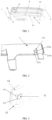
FIG. 1 is a schematic diagram of a fitting relationship between an outer belt weatherstrip and a vehicle door sheet metal provided in an embodiment of the present application. -
FIG. 2 is a structure diagram of a joint corner of a hidden outer belt weatherstrip provided in an embodiment of the present application. -
FIG. 3 is a structural diagram of a stud being welded to a vehicle door sheet metal provided in an embodiment of the present application. -
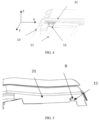
FIG. 4 is a structural diagram of an injection-molded joint corner of a hidden outer belt weatherstrip being limited to a vehicle door outer plate in a Y-direction provided in an embodiment of the present application. -
FIG. 5 is a structure diagram of an injection-molded joint corner of a hidden outer belt weatherstrip being limited to a vehicle door outer plate in a Z-direction provided in an embodiment of the present application. - In the -figures: 1Vehicle door sheet metal; 2-Outer belt weatherstrip; 3-Inner belt weatherstrip; 4-Vehicle window glass; 11-First positioning member; Positioning column-111; Limiting block-112; 12-Vehicle door inner plate; 13- Vehicle door outer plate; 14-Lip edge; 21-First injection-molded joint corner; 31-Second injection-molded joint corner; 211-First positioning portion; 211a-Accommodating area; 211b-Opening; 211c-Guiding edge; A-Demarcation point between inner and outer belt weatherstrips; B-Contact point fitting in Z-direction.
- The technical solutions in the embodiments of the present utility model will be clearly and comprehensively described hereunder in conjunction with the accompanying drawings in the embodiments of the present utility model. Apparently, the described embodiments are merely a part of the embodiments of the present utility model, rather than all embodiments of the present utility model. All other embodiments obtained by those of ordinary skill in the art based on the embodiments of the present utility model without any creative effort shall fall within the scope of protection of the present utility model.
- It should be noted that the terms such as "first", "second" and the like in the specification and the claims as well as the foregoing accompany drawings of the present utility model are used to distinguish similar objects, but not intended to describe a specific order or sequence. It should be appreciated that the data used in this way is interchangeable under appropriate circumstances, such that the embodiments of the present utility model as described herein can be implemented in an order other than those illustrated or described herein. Moreover, the terms such as "include" and "have" and any variations thereof are intended to cover a non-exclusive inclusion, e.g., processes, methods, apparatuses, products or devices that encompass a series of steps or units are not necessarily limited to those steps or units that are explicitly listed, but may include other steps or units that are not explicitly listed or inherent to these processes, methods, products or devices.
- The embodiments are described hereunder with reference to the accompanying drawings, and in no way would the accompanying drawings limit the utility model contents recited in the claims.
- With reference to
FIG. 1 to FIG. 5 , an embodiment of the present application provides a hidden belt weatherstrip assembly, which is provided on a vehicle door sheet metal 1 provided with a first positioning member 111, and includes anouter belt weatherstrip 2, where a first injection-moldedjoint corner 21 is provided on an end side of theouter belt weatherstrip 2, and afirst positioning portion 211 is provided on the first injection-moldedjoint corner 21; and where the first injection-moldedjoint corner 21 is fixed to the vehicle door sheet metal 1, and thefirst positioning member 11 is fitted to thefirst positioning portion 211. - In this way, the present application takes advantage of a fitted connection between the
first positioning portion 211 provided at theouter belt weatherstrip 2 and thefirst positioning member 11 of the vehicle door sheet metal 1, so that it is convenient to install and position theouter belt weatherstrip 2, and further a hemming area of the vehicle door sheet metal 1 is reasonably covered on the basis of providing the first injection-moldedjoint corner 21 to theouter belt weatherstrip 2, thereby avoiding a problem of poor appearance caused by hemming of the sheet metal in an irregular area after the vehicle door is opened. - In some embodiments, the hidden belt weatherstrip assembly further includes an inner belt weatherstrip 3, where the inner belt weatherstrip 3 is provided corresponding to the
outer belt weatherstrip 2. - Specifically, the vehicle door sheet metal 1 is divided into a vehicle door
inner plate 12 and a vehicle doorouter plate 13, and both the inner belt weatherstrip 3 and theouter belt weatherstrip 2 are fixed to the vehicle doorinner plate 12, in particular, both the inner belt weatherstrip 3 and theouter belt weatherstrip 2 can be clamped to the vehicle doorinterior plate 12. The inner belt weatherstrip 3 is located below the outer belt weatherstrip 2 (see a mark A inFIG. 1 for a demarcation line between the inner and outer belt weatherstrips), and the inner belt weatherstrip 3 and theouter belt weatherstrip 2 are provided with a lip edge 14 contactable with a vehicle window glass 4, so that water droplets, steams and dusts on the glass surface are cut off when the vehicle window glass 4 is regulated, improving sealing performance between the hidden belt weatherstrip assembly and the vehicle window glass 4, and when in use, the rainwater can be effectively prevented from passing through the hidden belt weatherstrip assembly to reach the inside of the vehicle doorexterior plate 13, playing an aesthetic role meanwhile. - In some embodiments, a second injection-molded joint corner 31 is provided on an end side of the inner belt weatherstrip 3, the second injection-molded joint corner 31 is fixed to the vehicle door sheet metal 1, and the second injection-molded joint corner 31 is provided corresponding to the first injection-molded
joint corner 21. By providing the second injection-molded joint corner 31 on the end side of the inner belt weatherstrip 3, a hemming area of the vehicle door sheet metal 1 can be reasonably covered by the inner belt weatherstrip 3. In the present embodiment, by correspondingly providing the second injection-molded joint corner 31 and the first injection-moldedjoint corner 21, the hemming area of the vehicle door sheet metal 1 can be covered in full jointly by the inner belt weatherstrip 3 and theouter belt weatherstrip 2. - In some embodiments, the
first positioning portion 211 is a slot provided on an inner side of theouter belt weatherstrip 2, the slot is an open structure with a notch downwards, and a depth of the slot is less than a thickness of a corresponding position of theouter belt weatherstrip 2, that is, the slot does not run through theouter belt weatherstrip 2 in a thickness direction of theouter belt weatherstrip 2. - Specifically, the slot has an
accommodating area 211a and an opening 211b in communication with theaccommodating area 211a, where the opening 211b of the slot is dimensionally matched with thefirst positioning member 11, the opening 211b of the slot is also provided with guidingedges 211c extending inclined outwards and downwards from the opening 211b to both sides, and two guidingedges 211c together form a flared shaped structure. During assembly, the opening 211b of the slot is oriented towards thefirst positioning member 11, and thefirst positioning member 11 smoothly enters the slot through the guidingedges 211c, facilitating the assembly of theouter belt weatherstrip 2 and the vehicle door sheet metal 1. - In some embodiments, the
first positioning member 11 includes a positioning column 111, and the positioning column 111 is provided to protrude towards theouter belt weatherstrip 2 along a sheet metal surface of the vehicle door sheet metal 1. In the present embodiment, the positioning column 111 protrudes and extends inwardly along the vehicle doorinner plate 12. - Further, a
limiting block 112 is provided at an end of the positioning column 111, and thelimiting block 112 is clamped into theaccommodating area 211a after the positioning column 111 passes through the opening 211b of the slot, so that theouter belt weatherstrip 2 is fixed to the vehicle doorinner plate 12. Thefirst positioning member 11 includes but is not limited to fasteners such as a bolt and a screw. In an embodiment, thefirst positioning member 11 is a bolt. - Specifically, in the present embodiment, the limiting block is added to the positioning column, so that the
accommodating area 211a on theouter belt weatherstrip 2 is clamped to the limitingblock 112 of the vehicle door sheet metal 1, thereby limiting theouter belt weatherstrip 2, and improving installation stability of theouter belt weatherstrip 2. - In some embodiments, the positioning column is in a welded connection with the vehicle door sheet metal 1.
- In the present embodiment, the positioning column is fixed to the vehicle door sheet metal 1 by means of welding, thus an installation reference is provided for the
outer belt weatherstrip 2, and theaccommodating area 211a on theouter belt weatherstrip 2 is clamped to the limitingblock 112 of the vehicle door sheet metal 1 during installation; in addition, the outer surface of theouter belt weatherstrip 2 abuts against the inner surface of the vehicle door sheet metal 1, thereby achieving the limiting of theouter belt weatherstrip 2 in the Y-direction of the vehicle body, and improving service life of the parts. - In some embodiments, the positioning column can also be fixed to the vehicle door sheet metal 1 by means of bonding, clamping or threaded connection.
- In some embodiments, the
first positioning member 11 is joint with the first injection-moldedjoint corner 21 on theouter belt weatherstrip 2 in a length direction of a vehicle body by a lap amount of 2.0 mm to 3.0 mm, that is, the positioning column 111 has a diameter of 2.0 mm to 3.0 mm. - Specifically, through the slot, the first injection-molded
joint corner 21 on theouter belt weatherstrip 2 in the present embodiment is clamped with a stud welded on the vehicle door sheet metal 1, and the welded stud is unilaterally joint with the first injection-moldedjoint corner 21 on theouter belt weatherstrip 2 by a lap amount of 2.5 mm in the X-direction, playing a role of X-direction limiting. - In some embodiments, the
first positioning member 11 is closely fitted to the first injection-moldedjoint corner 21 on theouter belt weatherstrip 2. - Specifically, through the slot, the first injection-molded
joint corner 21 on theouter belt weatherstrip 2 is clamped with the stud welded on the vehicle door sheet metal 1; the welded stud and the first injection-moldedjoint corner 21 on theouter belt weatherstrip 2 have a contact clearance of zero in the Z-direction (see a mark B inFIG. 5 for a contact point fitting in the Z-direction), hence playing a role of Z-direction positioning for the outer belt weatherstrip during assembly. - In some embodiments, the first injection-molded
joint corner 21 and thefirst positioning portion 211 are integrally formed by injection molding. - Specifically, the integral injection molding can ensure stability of structure of the first injection-molded
joint corner 21, so that it is convenient for mass production. - In some embodiments, a second positioning portion is provided on the second injection-molded joint corner 31, a second positioning member is provided on the vehicle door sheet metal 1, and the second positioning member is fitted to the second positioning portion.
- In the present embodiment, in order to facilitate the positioning and installation of the inner belt weatherstrip 3, the second positioning portion is provided as a slot in terms of its structure, and the second positioning portion is provided as a positioning column in terms of its structure, and a specific arrangement relationship therebetween is the same as the arrangement relationship in the outer belt weatherstrip, hence details will not be described here again.
- In some embodiments, the present application in another aspect provides a vehicle door, including the vehicle door sheet metal 1 and the hidden belt weatherstrip assembly as described above.
- For the hidden belt weatherstrip assembly disclosed in the utility model, an injection-molded joint corner structure is provided on the outer belt weatherstrip, and cooperates with the injection-molded joint corner for the inner belt weatherstrip, to reasonably cover the hemming area of the vehicle door sheet metal, thereby avoiding the problem of poor appearance caused by sheet metal hemmings in an irregular area after the vehicle door is opened; the slot is opened on the injection-molded joint corner structure of the outer belt weatherstrip, and cooperates with the positioning column welded on the vehicle door sheet metal, thereby solving the problems that it is impossible to provide installation and positioning references on the vehicle door sheet metal for the hidden outer belt weatherstrip and the Y-direction limiting is impossible due to the limited space of the vehicle door modelling, and meanwhile improving the durability of the parts; plus, a positioning surface will also be provided for the concealed belt line molding, which solves the problem that the Z-direction positioning is impossible for the hidden outer belt weatherstrip during assembly.
- The embodiments in the specification are described progressively, and cross reference can be made to the embodiments for the same and similar parts therebetween, where each embodiment focuses on differences from other embodiments.
- It should be noted that all the features recorded in the present application (including the technical features recorded in different embodiments) can be arbitrarily combined under reasonable circumstances, and all the new technical solutions formed by the combination are within the scope of protection of the present application.
- The above descriptions are merely preferred embodiments of the present utility model, and shall not be considered as a limitation to the present utility model. Any modifications, equivalent replacements, and improvements within the spirit and the principle of the present utility modelshall be included in the scope of protection of the present utility model.
Claims (14)
- A hidden belt weatherstrip assembly, which is provided on a vehicle door sheet metal (1) provided with a first positioning member (11), comprising an outer belt weatherstrip (2), wherein a first injection-molded joint corner (21) is provided on an end side of the outer belt weatherstrip (2), and a first positioning portion (211) is provided on the first injection-molded joint corner (21); and
wherein the first positioning member (11) is fitted to the first positioning portion (211), and the first injection-molded joint corner (21) is fixed to the vehicle door sheet metal (1). - The hidden belt weatherstrip assembly according to claim 1, further comprising: an inner belt weatherstrip (3), wherein the inner belt weatherstrip (3) is located below the outer belt weatherstrip (2).
- The hidden belt weatherstrip assembly according to claim 2, wherein a second injection-molded joint corner (31) is provided on an end side of the inner belt weatherstrip (3), the second injection-molded joint corner (31) is fixed to the vehicle door sheet metal (1), and the second injection-molded joint corner (31) is provided corresponding to the first injection-molded joint corner (21).
- The hidden belt weatherstrip assembly according to claim 1, wherein the first positioning portion (211) is a slot.
- The hidden belt weatherstrip assembly according to claim 4, wherein the slot has an accommodating area (211a) and an opening (211b) in communication with the accommodating area (211a), and the first positioning member (11) is clamped into the accommodating area (211a) through the opening (211b).
- The hidden belt weatherstrip assembly according to claim 5, wherein the slot further has guiding edges (211c) extending inclined outwards and downwards from the opening (211b) to both sides.
- The hidden belt weatherstrip assembly according to claim 4, wherein a depth of the slot is less than a thickness of a corresponding position of the outer belt weatherstrip (2).
- The hidden belt weatherstrip assembly according to claim 1, wherein the first positioning member (11) comprises a positioning column, and the positioning column is provided to protrude towards the outer belt weatherstrip (2) along a sheet metal surface of the vehicle door sheet metal (1).
- The hidden belt weatherstrip assembly according to claim 8, wherein a limiting block (112) is provided at an end of the positioning column (111), and the limiting block (112) is clamped into the first positioning portion (211).
- The hidden belt weatherstrip assembly according to claim 8, wherein the positioning column is in a welded connection with the vehicle door sheet metal (1).
- The hidden belt weatherstrip assembly according to any one of claims 1 to 10, wherein the first positioning member (11) is joint with the first injection-molded joint corner (21) in a length direction of a vehicle body by a lap amount of 2.0 mm to 3.0 mm.
- The hidden belt weatherstrip assembly according to any one of claims 1 to 10, wherein the first positioning member (11) is closely connected with the first injection-molded joint corner (21).
- The hidden belt weatherstrip assembly according to claim 4, wherein the first injection-molded joint corner (21) and the first positioning portion (211) are integrally formed by injection molding; the slot is an open structure with a notch downwards.
- The hidden belt weatherstrip assembly according to claim 3, wherein a second positioning portion is provided on the second injection-molded joint corner (31), a second positioning member is provided on the vehicle door sheet metal (1), and the second positioning member is fitted to the second positioning portion.
Applications Claiming Priority (2)
| Application Number | Priority Date | Filing Date | Title |
|---|---|---|---|
| CN202221192073.1U CN217863668U (en) | 2022-05-17 | 2022-05-17 | Subassembly is cut to hidden water |
| PCT/CN2023/094696 WO2023222015A1 (en) | 2022-05-17 | 2023-05-17 | Concealed belt molding assembly |
Publications (2)
| Publication Number | Publication Date |
|---|---|
| EP4527652A1 true EP4527652A1 (en) | 2025-03-26 |
| EP4527652A4 EP4527652A4 (en) | 2026-04-15 |
Family
ID=84090946
Family Applications (1)
| Application Number | Title | Priority Date | Filing Date |
|---|---|---|---|
| EP23806966.0A Pending EP4527652A4 (en) | 2022-05-17 | 2023-05-17 | CONCEALED BELT FORM ARRANGEMENT |
Country Status (4)
| Country | Link |
|---|---|
| US (1) | US20250065703A1 (en) |
| EP (1) | EP4527652A4 (en) |
| CN (1) | CN217863668U (en) |
| WO (1) | WO2023222015A1 (en) |
Families Citing this family (2)
| Publication number | Priority date | Publication date | Assignee | Title |
|---|---|---|---|---|
| CN217863668U (en) * | 2022-05-17 | 2022-11-22 | 浙江极氪智能科技有限公司 | Subassembly is cut to hidden water |
| US12403754B2 (en) * | 2023-04-18 | 2025-09-02 | Rivian Ip Holdings, Llc | Hidden outer belt seal |
Family Cites Families (16)
| Publication number | Priority date | Publication date | Assignee | Title |
|---|---|---|---|---|
| JP2593725Y2 (en) * | 1992-07-09 | 1999-04-12 | 株式会社東郷製作所 | Door belt molding clip |
| US5275455A (en) * | 1992-10-07 | 1994-01-04 | Chrysler Corporation | Integral molding snap-in attachment fastener |
| KR100588692B1 (en) * | 2004-06-22 | 2006-06-12 | 기아자동차주식회사 | Mounting structure of car doorside weather strip |
| US20090151266A1 (en) * | 2007-12-13 | 2009-06-18 | Cooper-Standard Automotive Inc. | Outer belt weatherstrip with snap-on molded shell |
| US8572897B2 (en) * | 2011-09-14 | 2013-11-05 | Ford Global Technologies, Llc | Weatherstrip cinch clip |
| DE102011121416A1 (en) * | 2011-12-17 | 2013-06-20 | Gm Global Technology Operations, Llc | Fixing element for use in seal arrangement for mounting seal to body component of motor vehicle, has mounting portion engageable and fixable with attachment element implementing seal bottom and comprising retainer in bottom section |
| PL2692566T3 (en) * | 2012-08-01 | 2019-03-29 | Henniges Automotive Sealing Systems North America, Inc. | Dual end cap for a seal assembly |
| JP6170464B2 (en) * | 2014-04-23 | 2017-07-26 | 本田技研工業株式会社 | Weather strip mounting structure |
| DE102016114353A1 (en) * | 2016-08-03 | 2018-02-08 | Daimler Ag | End cap for an illuminated trim strip arrangement and trim strip arrangement |
| CN207617480U (en) * | 2017-11-23 | 2018-07-17 | 上汽通用五菱汽车股份有限公司 | A kind of water cut end cap assemblies |
| CN208530251U (en) * | 2018-04-02 | 2019-02-22 | 北京汽车股份有限公司 | External water cutting fixtures and automobiles |
| CN208558993U (en) * | 2018-06-29 | 2019-03-01 | 上海思致汽车工程技术有限公司 | A kind of outer water of arrangements for automotive doors is cut and car door metal plate mounting structure |
| US10889171B2 (en) * | 2018-10-05 | 2021-01-12 | Honda Motor Co., Ltd. | Vehicle door assembly with weatherstrip and methods of use and manufacture thereof |
| CN110370904B (en) * | 2019-07-17 | 2020-12-15 | 吉利汽车研究院(宁波)有限公司 | A kind of installation structure and vehicle for water cutting outside the door and body sheet metal |
| CN216374137U (en) * | 2021-08-05 | 2022-04-26 | 库博标准投资有限公司 | Combined installation buckle structure |
| CN217863668U (en) * | 2022-05-17 | 2022-11-22 | 浙江极氪智能科技有限公司 | Subassembly is cut to hidden water |
-
2022
- 2022-05-17 CN CN202221192073.1U patent/CN217863668U/en active Active
-
2023
- 2023-05-17 EP EP23806966.0A patent/EP4527652A4/en active Pending
- 2023-05-17 WO PCT/CN2023/094696 patent/WO2023222015A1/en not_active Ceased
-
2024
- 2024-11-15 US US18/948,822 patent/US20250065703A1/en active Pending
Also Published As
| Publication number | Publication date |
|---|---|
| CN217863668U (en) | 2022-11-22 |
| US20250065703A1 (en) | 2025-02-27 |
| WO2023222015A1 (en) | 2023-11-23 |
| EP4527652A4 (en) | 2026-04-15 |
Similar Documents
| Publication | Publication Date | Title |
|---|---|---|
| US20250065703A1 (en) | Hidden belt weatherstrip assembly | |
| CN111532115B (en) | Door outer water cut, door and car | |
| US20090195013A1 (en) | Vehicle door sash structure | |
| CN114932794A (en) | Hidden extra income is cut and is had its vehicle | |
| CN219706652U (en) | Vehicle door assembly and vehicle | |
| CN218400171U (en) | Roof sealing structure of convertible car and convertible car | |
| CN207345459U (en) | A kind of B columns door sash | |
| JP3818069B2 (en) | Automotive door trim | |
| CN212313457U (en) | Automobile C column decorative plate mounting structure | |
| CN223574185U (en) | Car window sealing and noise reduction structure and vehicle | |
| CN219727841U (en) | Tail door dustproof strip | |
| CN114643843A (en) | Split type extra income is cut structure and vehicle | |
| CN222432038U (en) | Outer water of door cuts, door and vehicle | |
| CN208576405U (en) | Car door | |
| CN223279028U (en) | Roof structure and vehicle | |
| CN223835377U (en) | Car door corner connecting structure and car door | |
| CN219387615U (en) | Electric back door sheet metal assembly and clamping strip prevention assembly matching structure | |
| CN223520753U (en) | A type of car door trim panel | |
| CN218877125U (en) | Automobile external pressure bar and sheet metal mounting structure | |
| CN217649284U (en) | Door sash upper sealing strip, vehicle door and vehicle | |
| CN222522443U (en) | Glass groove for vehicle door | |
| CN221457287U (en) | Water cutting assembly in door, door and vehicle | |
| CN120882624A (en) | Vehicle window seal assembly | |
| CN223750970U (en) | Vehicle vent flap and vehicle | |
| CN222769234U (en) | Outer water of door cuts structure and vehicle |
Legal Events
| Date | Code | Title | Description |
|---|---|---|---|
| STAA | Information on the status of an ep patent application or granted ep patent |
Free format text: STATUS: THE INTERNATIONAL PUBLICATION HAS BEEN MADE |
|
| PUAI | Public reference made under article 153(3) epc to a published international application that has entered the european phase |
Free format text: ORIGINAL CODE: 0009012 |
|
| STAA | Information on the status of an ep patent application or granted ep patent |
Free format text: STATUS: REQUEST FOR EXAMINATION WAS MADE |
|
| 17P | Request for examination filed |
Effective date: 20241206 |
|
| AK | Designated contracting states |
Kind code of ref document: A1 Designated state(s): AL AT BE BG CH CY CZ DE DK EE ES FI FR GB GR HR HU IE IS IT LI LT LU LV MC ME MK MT NL NO PL PT RO RS SE SI SK SM TR |
|
| DAV | Request for validation of the european patent (deleted) | ||
| DAX | Request for extension of the european patent (deleted) | ||
| A4 | Supplementary search report drawn up and despatched |
Effective date: 20260317 |
|
| RIC1 | Information provided on ipc code assigned before grant |
Ipc: B60J 10/30 20160101AFI20260311BHEP Ipc: B60J 10/76 20160101ALI20260311BHEP Ipc: B60J 10/86 20160101ALI20260311BHEP |