EP4527605A1 - Method for producing repaired pneumatic tire - Google Patents
Method for producing repaired pneumatic tire Download PDFInfo
- Publication number
- EP4527605A1 EP4527605A1 EP23807220.1A EP23807220A EP4527605A1 EP 4527605 A1 EP4527605 A1 EP 4527605A1 EP 23807220 A EP23807220 A EP 23807220A EP 4527605 A1 EP4527605 A1 EP 4527605A1
- Authority
- EP
- European Patent Office
- Prior art keywords
- tire
- repaired
- repair patch
- radial direction
- pneumatic tire
- Prior art date
- Legal status (The legal status is an assumption and is not a legal conclusion. Google has not performed a legal analysis and makes no representation as to the accuracy of the status listed.)
- Pending
Links
Images


Classifications
-
- B—PERFORMING OPERATIONS; TRANSPORTING
- B29—WORKING OF PLASTICS; WORKING OF SUBSTANCES IN A PLASTIC STATE IN GENERAL
- B29D—PRODUCING PARTICULAR ARTICLES FROM PLASTICS OR FROM SUBSTANCES IN A PLASTIC STATE
- B29D30/00—Producing pneumatic or solid tyres or parts thereof
- B29D30/06—Pneumatic tyres or parts thereof (e.g. produced by casting, moulding, compression moulding, injection moulding, centrifugal casting)
- B29D30/0681—Parts of pneumatic tyres; accessories, auxiliary operations
-
- B—PERFORMING OPERATIONS; TRANSPORTING
- B29—WORKING OF PLASTICS; WORKING OF SUBSTANCES IN A PLASTIC STATE IN GENERAL
- B29C—SHAPING OR JOINING OF PLASTICS; SHAPING OF MATERIAL IN A PLASTIC STATE, NOT OTHERWISE PROVIDED FOR; AFTER-TREATMENT OF THE SHAPED PRODUCTS, e.g. REPAIRING
- B29C73/00—Repairing of articles made from plastics or substances in a plastic state, e.g. of articles shaped or produced by using techniques covered by this subclass or subclass B29D
- B29C73/04—Repairing of articles made from plastics or substances in a plastic state, e.g. of articles shaped or produced by using techniques covered by this subclass or subclass B29D using preformed elements
- B29C73/10—Repairing of articles made from plastics or substances in a plastic state, e.g. of articles shaped or produced by using techniques covered by this subclass or subclass B29D using preformed elements using patches sealing on the surface of the article
-
- B—PERFORMING OPERATIONS; TRANSPORTING
- B29—WORKING OF PLASTICS; WORKING OF SUBSTANCES IN A PLASTIC STATE IN GENERAL
- B29D—PRODUCING PARTICULAR ARTICLES FROM PLASTICS OR FROM SUBSTANCES IN A PLASTIC STATE
- B29D30/00—Producing pneumatic or solid tyres or parts thereof
- B29D30/06—Pneumatic tyres or parts thereof (e.g. produced by casting, moulding, compression moulding, injection moulding, centrifugal casting)
- B29D30/52—Unvulcanised treads, e.g. on used tyres; Retreading
- B29D30/54—Retreading
-
- B—PERFORMING OPERATIONS; TRANSPORTING
- B29—WORKING OF PLASTICS; WORKING OF SUBSTANCES IN A PLASTIC STATE IN GENERAL
- B29L—INDEXING SCHEME ASSOCIATED WITH SUBCLASS B29C, RELATING TO PARTICULAR ARTICLES
- B29L2030/00—Pneumatic or solid tyres or parts thereof
Definitions
- This disclosure relates to a method for producing a repaired pneumatic tire.
- a conventional method for repairing a pneumatic tire has been proposed, in which a repair patch is applied to a pneumatic tire to repair penetrations in the sidewall portion and the tread portion (e.g., PTL 1).
- the gist structure of the present disclosure is as follows.
- a method for producing a repaired pneumatic tire comprising a carcass extending in a toroidal shape between a pair of bead portions and a belt consisting of one or more belt layers disposed on an outer side in the tire radial direction of a crown portion of the carcass, wherein the method includes:
- the "tire maximum width position” refers to the position at which the width in the tire width direction is maximum when a repaired pneumatic tire is mounted on an applicable rim, filled with a prescribed internal pressure, and unloaded.
- the "applicable rim” refers to the standard rim in the applicable size (Measuring Rim in ETRTO's STANDARDS MANUAL and Design Rim in TRA's YEAR BOOK) as described or as may be described in the future in the industrial standard, which is valid for the region in which the tire is produced and used, such as JATMA YEAR BOOK of JATMA (Japan Automobile Tyre Manufacturers Association) in Japan , STANDARDS MANUAL of ETRTO (The European Tyre and Rim Technical Organization) in Europe , and YEAR BOOK of TRA (The Tire and Rim Association, Inc.) in the United States (That is, the above "rim” includes current sizes as well as sizes that may be listed in the aforementioned industrial standards in the future.
- the "applicable rim” refers to a rim with a width corresponding to the bead width of the tire.
- the "prescribed internal pressure” refers to the air pressure (maximum air pressure) corresponding to the maximum load capacity of a single wheel in the applicable size and ply rating, as described in the aforementioned JATMA and other industrial standards. In the case that the size is not listed in the aforementioned industrial standards, the “prescribed internal pressure” refers to the air pressure (maximum air pressure) corresponding to the maximum load capacity specified for each vehicle in which the tire is mounted.
- FIG 1 is a cross-sectional view in the tire width direction of a repaired pneumatic tire produced by the method for producing a repaired pneumatic tire according to one embodiment of this disclosure.
- this repaired pneumatic tire (hereinafter, referred to simply as "tire") 1 comprises a carcass 3 extending in a toroidal shape between a pair of bead portions 2; and a belt 4 consisting of one or more belt layers 4a, 4b, 4c (three layers in the illustrated example) disposed on an outer side in the tire radial direction of a crown portion of the carcass 3 and a tread 5.
- a bead core 2a is embedded in each of the pair of bead portions 2.
- a bead filler may be appropriately disposed on the outer side of the bead core 2a in the tire radial direction.
- the carcass 3 consists of one or more carcass plies, and the carcass plies can be made of, for example, organic fiber cords.
- the carcass 3 consists of a carcass body portion extending in a toroidal shape between the pair of bead portions 2 and carcass turn-up portions that are folded around each of the bead cores 2a from the carcass body portion, respectively.
- the inner-most belt layer 4a in the tire radial direction has the largest width in the tire width direction and the outer-most belt layer 4c in the tire width direction has the smallest width, however, the relationship between the width of each belt layer in the tire width direction is not limited to this example and can be changed as needed.
- the belt cord may be, for example, a steel cord.
- the inclination angle of the belt cord relative to the tire circumferential direction can be, for example, 30° to 60°.
- a belt reinforcement layer (for example, a belt reinforcement layer with cords extending in the tire circumferential direction) may be further provided on the outer or inner side in the tire radial direction of the belt 4 as appropriate.
- the tread 5 is made of tread rubber.
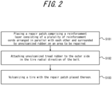
- FIG 2 is a flowchart of the method for producing a repaired pneumatic tire according to one embodiment of this disclosure.
- a repair patch comprising a reinforcement layer consisting of a plurality of reinforcement cords arranged in parallel with each other and surrounded by unvulcanized rubber, is placed on an area to be repaired of a pre-repaired pneumatic tire (A placement process: step S101).
- a placement process: step S101 unvulcanized tread rubber is attached to the outer side in the tire radial direction of the belt
- a tread rubber attachment process: step S102 A tread rubber attachment process: step S102
- the step S102 may be omitted as appropriate.
- the tire with the repair patch placed thereon is vulcanized (A vulcanization process: step S103).
- vulcanization is performed using a mold in the vulcanization process.
- the mold may have a groove.
- the temperature of the mold during vulcanization is 130 °C to 170 °C, and the pressure of hot water in a vulcanizing bladder is 1.3 MPa to 2.1 MPa.
- the repaired pneumatic tire repaired through this process further comprises a repair patch 6 on the inner surface of the tire (inner surface of the inner liner, not illustrated).
- the outer end in the tire radial direction of the repair patch 6 is located on the inner side in the tire width direction than the end of the maximum width belt layer that has the largest width in the tire width direction among the one or more belt layers (belt layer 3a, in this example), and the inner end in the tire radial direction of the repair patch 6 is located on the outer side in the tire radial direction than the tire maximum width position P.
- this method can be used to repair a wide range of repairs, such as a penetration that occurs near the maximum width belt layer.
- the size of the repair patch can be reduced (compared to the case in which the inner end in the tire radial direction of the repair patch 6 is located on the inner side in the tire radial direction than the tire maximum width position P) and the cost of the repair patch 6 itself can be reduced.
- the size of the repair patch is not increased as much as possible.
- a tread rubber attachment process attaching unvulcanized tread rubber to the outer side in the tire radial direction of the belt. This allows for repairing and retreading at the same time.
- the placement process and the tread rubber attachment process mentioned above may be performed either first or simultaneously, however, from the standpoint of workability, it is preferable to perform the placement process first, as in this embodiment.
- a mold is used; the temperature of the mold during vulcanization is 130 °C to 170 °C; and the pressure of the hot water in the vulcanizing bladder is 1.0 MPa to 2.5 MPa.
- the adhesion of the repair patch can be improved by setting the temperature of the mold during vulcanization to 130 °C or higher and the pressure of the hot water in the vulcanizing bladder to 1.0 MPa or higher.
- the temperature of the mold during vulcanization is preferably 170 °C or lower.
- the pressure of the hot water in the vulcanizing bladder is preferably 2.5 MPa or less.
- the temperature of the mold during vulcanization is between 140 °C and 160 °C.
- Figure 3 is a schematic drawing illustrating the structure of the repair patch.
- the repair patch 6 comprises a reinforcement layer consisting of a plurality of reinforcement cords arranged parallel to each other and surrounded by unvulcanized rubber.
- the reinforcement cords for the repair patch are not limited, but organic fibers such as nylon PET and aramid can be used.
- the number of the reinforcement layers in the repair patch is preferably one or more and four or less. This is to prevent defects from occurring during vulcanization.
- Figure 3 illustrates an example of a repair patch consisting of four reinforcement layers. It should be noted that reinforcing cords for the layers 6a and 6d are not illustrated in the drawings.
- the post-repaired tire thickness t2 is preferably between 103 and 125.
- a value of 103 or higher ensures the effectiveness of the repair, while a value of 125 or lower prevents defects from occurring during vulcanization.
- the "tire thickness” here refers to the thickness from the tread surface to the inner surface of the tire (or inner surface of the inner liner, if an inner liner is provided) at the repaired area, and the tire thickness shall be measured in a direction normal to the carcass, passing through the belt end of the maximum width belt layer, with the repaired pneumatic tire mounted on the applicable rim, filled with the prescribed internal pressure, and unloaded.
- the pre-repaired tire thickness t1 is obtained by subtracting from the post-repaired tire thickness t2 the thickness of the repair patch 6 measured in a direction normal to the carcass, passing through the belt end of the maximum width belt layer in the aforementioned condition.
- repair patch 6 can be done by the same method as before, and is not limited to any particular method, but one example is as follows. First, removing tire rubber and an inner liner around the repair area; filling the repair area with unvulcanized rubber; and then performing the placement process placing a repair patch (step S101).
Landscapes
- Engineering & Computer Science (AREA)
- Mechanical Engineering (AREA)
- Tyre Moulding (AREA)
Abstract
Description
- This disclosure relates to a method for producing a repaired pneumatic tire.
- A conventional method for repairing a pneumatic tire has been proposed, in which a repair patch is applied to a pneumatic tire to repair penetrations in the sidewall portion and the tread portion (e.g., PTL 1).
- When repairing penetrations in the shoulder portion of a pneumatic tire, if the repair patch is placed so that the end of the patch is located in an area of high tire deformation (specifically, the area from the end of the maximum width belt layer that has the largest width among the belt layers to the tire maximum width position), tire deformation could cause the repair patch to peel off from its ends. Therefore, conventionally, the size of the repair patch was increased so that both ends of the repair patch would be located outside the area of high tire deformation mentioned above.
- PTL 1:
WO 2012/111347 - However, the cost of the repair patch increases with the size of the repair patch, so the larger the size of the repair patch, the higher the cost.
- It is therefore an object of the present disclosure to provide a method for producing a repaired pneumatic tire in which the size of the repair patch is not increased as much as possible.
- The gist structure of the present disclosure is as follows.
- A method for producing a repaired pneumatic tire, comprising a carcass extending in a toroidal shape between a pair of bead portions and a belt consisting of one or more belt layers disposed on an outer side in the tire radial direction of a crown portion of the carcass, wherein the method includes:
- a placement process placing a repair patch, comprising a reinforcement layer consisting of a plurality of reinforcement cords arranged in parallel with each other and surrounded by unvulcanized rubber, on an area to be repaired; and
- a vulcanization process vulcanizing a tire with the repair patch placed thereon, and
- in the repaired pneumatic tire, an outer end in the tire radial direction of the repair patch is located on an inner side in the tire width direction than an end of a maximum width belt layer that has the largest width in the tire width direction among the one or more belt layers, and an inner end in the tire radial direction of the repair patch is located on an outer side in the tire radial direction than a tire maximum width position.
- Here, the "tire maximum width position" refers to the position at which the width in the tire width direction is maximum when a repaired pneumatic tire is mounted on an applicable rim, filled with a prescribed internal pressure, and unloaded.
- In addition, the "applicable rim" refers to the standard rim in the applicable size (Measuring Rim in ETRTO's STANDARDS MANUAL and Design Rim in TRA's YEAR BOOK) as described or as may be described in the future in the industrial standard, which is valid for the region in which the tire is produced and used, such as JATMA YEAR BOOK of JATMA (Japan Automobile Tyre Manufacturers Association) in Japan, STANDARDS MANUAL of ETRTO (The European Tyre and Rim Technical Organization) in Europe, and YEAR BOOK of TRA (The Tire and Rim Association, Inc.) in the United States (That is, the above "rim" includes current sizes as well as sizes that may be listed in the aforementioned industrial standards in the future. An example of the "sizes that may be listed in the future" could be the sizes listed as "FUTURE DEVELOPMENTS" in the ETRTO 2013 edition.). For sizes not listed in these industrial standards, the "applicable rim" refers to a rim with a width corresponding to the bead width of the tire.
- In addition, the "prescribed internal pressure" refers to the air pressure (maximum air pressure) corresponding to the maximum load capacity of a single wheel in the applicable size and ply rating, as described in the aforementioned JATMA and other industrial standards. In the case that the size is not listed in the aforementioned industrial standards, the "prescribed internal pressure" refers to the air pressure (maximum air pressure) corresponding to the maximum load capacity specified for each vehicle in which the tire is mounted.
- According to the present disclosure, it is possible to provide a method for producing a repaired pneumatic tire in which the size of the repair patch is not increased as much as possible.
- In the accompanying drawings:
-
FIG. 1 is a cross-sectional view in the tire width direction of a repaired pneumatic tire produced by the method for producing a repaired pneumatic tire according to one embodiment of this disclosure; -
FIG. 2 is a flowchart of the method for producing a repaired pneumatic tire according to one embodiment of this disclosure; and -
FIG. 3 is a schematic drawing illustrating the structure of the repair patch. - Hereinafter, embodiments of the present disclosure will be described in detail with reference to the drawings.
-
Figure 1 is a cross-sectional view in the tire width direction of a repaired pneumatic tire produced by the method for producing a repaired pneumatic tire according to one embodiment of this disclosure. As illustrated inFigure 1 , this repaired pneumatic tire (hereinafter, referred to simply as "tire") 1 comprises a carcass 3 extending in a toroidal shape between a pair ofbead portions 2; and abelt 4 consisting of one ormore belt layers tread 5. - A
bead core 2a is embedded in each of the pair ofbead portions 2. A bead filler may be appropriately disposed on the outer side of thebead core 2a in the tire radial direction. The carcass 3 consists of one or more carcass plies, and the carcass plies can be made of, for example, organic fiber cords. In this example, the carcass 3 consists of a carcass body portion extending in a toroidal shape between the pair ofbead portions 2 and carcass turn-up portions that are folded around each of thebead cores 2a from the carcass body portion, respectively. In this example, there are three belt layers, but the number of belt layers can be one or more. In addition, in this example, theinner-most belt layer 4a in the tire radial direction has the largest width in the tire width direction and theouter-most belt layer 4c in the tire width direction has the smallest width, however, the relationship between the width of each belt layer in the tire width direction is not limited to this example and can be changed as needed. The belt cord may be, for example, a steel cord. The inclination angle of the belt cord relative to the tire circumferential direction can be, for example, 30° to 60°. Furthermore, a belt reinforcement layer (for example, a belt reinforcement layer with cords extending in the tire circumferential direction) may be further provided on the outer or inner side in the tire radial direction of thebelt 4 as appropriate. Thetread 5 is made of tread rubber. -
Figure 2 is a flowchart of the method for producing a repaired pneumatic tire according to one embodiment of this disclosure. As illustrated inFigure 2 , in this embodiment, a repair patch, comprising a reinforcement layer consisting of a plurality of reinforcement cords arranged in parallel with each other and surrounded by unvulcanized rubber, is placed on an area to be repaired of a pre-repaired pneumatic tire (A placement process: step S101). Next, in this example, unvulcanized tread rubber is attached to the outer side in the tire radial direction of the belt (A tread rubber attachment process: step S102). Note, that the step S102 may be omitted as appropriate. Next, the tire with the repair patch placed thereon is vulcanized (A vulcanization process: step S103). In this embodiment, vulcanization is performed using a mold in the vulcanization process. The mold may have a groove. In addition, in this embodiment, in the vulcanization process, the temperature of the mold during vulcanization is 130 °C to 170 °C, and the pressure of hot water in a vulcanizing bladder is 1.3 MPa to 2.1 MPa. - The repaired pneumatic tire repaired through this process further comprises a
repair patch 6 on the inner surface of the tire (inner surface of the inner liner, not illustrated). As illustrated inFigure 1 , the outer end in the tire radial direction of therepair patch 6 is located on the inner side in the tire width direction than the end of the maximum width belt layer that has the largest width in the tire width direction among the one or more belt layers (belt layer 3a, in this example), and the inner end in the tire radial direction of therepair patch 6 is located on the outer side in the tire radial direction than the tire maximum width position P. - The effects of the method for producing a repaired pneumatic tire according to this embodiment will be described.
- According to the method for producing a repaired pneumatic tire according to this embodiment, since, in the repaired pneumatic tire, the outer end in the tire radial direction of the
repair patch 6 is located on the inner side in the tire width direction than the end of the maximum width belt layer that has the largest width in the tire width direction among the one or more belt layers (belt layer 3a, in this example), this method can be used to repair a wide range of repairs, such as a penetration that occurs near the maximum width belt layer. On the other hand, since the inner end in the tire radial direction of therepair patch 6 is located on the outer side in the tire radial direction than the tire maximum width position P, the size of the repair patch can be reduced (compared to the case in which the inner end in the tire radial direction of therepair patch 6 is located on the inner side in the tire radial direction than the tire maximum width position P) and the cost of therepair patch 6 itself can be reduced. - Thus, according to the method for producing a repaired pneumatic tire according to this embodiment, it is possible that the size of the repair patch is not increased as much as possible.
- As in the present embodiment, it is preferable to further include, before the vulcanization process, a tread rubber attachment process attaching unvulcanized tread rubber to the outer side in the tire radial direction of the belt. This allows for repairing and retreading at the same time. Note, that the placement process and the tread rubber attachment process mentioned above may be performed either first or simultaneously, however, from the standpoint of workability, it is preferable to perform the placement process first, as in this embodiment.
- In addition, in the vulcanization process, as in the present embodiment, it is preferable that: a mold is used; the temperature of the mold during vulcanization is 130 °C to 170 °C; and the pressure of the hot water in the vulcanizing bladder is 1.0 MPa to 2.5 MPa. By performing vulcanization under such high temperature and pressure conditions, sufficient adhesion can be ensured even if the end of the repair patch is located in the area of high tire deformation, from the end of the maximum width belt layer to the maximum tire width position. In other words, the adhesion of the repair patch can be improved by setting the temperature of the mold during vulcanization to 130 °C or higher and the pressure of the hot water in the vulcanizing bladder to 1.0 MPa or higher. On the other hand, from the viewpoint of controlling thermal degradation of rubber, the temperature of the mold during vulcanization is preferably 170 °C or lower. In addition, from the viewpoint of patch formability after vulcanization, the pressure of the hot water in the vulcanizing bladder is preferably 2.5 MPa or less. For the same reasons as above, it is further preferred that the temperature of the mold during vulcanization is between 140 °C and 160 °C.
-
Figure 3 is a schematic drawing illustrating the structure of the repair patch. As mentioned above, therepair patch 6 comprises a reinforcement layer consisting of a plurality of reinforcement cords arranged parallel to each other and surrounded by unvulcanized rubber. The reinforcement cords for the repair patch are not limited, but organic fibers such as nylon PET and aramid can be used. The number of the reinforcement layers in the repair patch is preferably one or more and four or less. This is to prevent defects from occurring during vulcanization.Figure 3 illustrates an example of a repair patch consisting of four reinforcement layers. It should be noted that reinforcing cords for thelayers - For the repaired area, when the pre-repaired tire thickness t1 is 100, the post-repaired tire thickness t2 is preferably between 103 and 125. A value of 103 or higher ensures the effectiveness of the repair, while a value of 125 or lower prevents defects from occurring during vulcanization. The "tire thickness" here refers to the thickness from the tread surface to the inner surface of the tire (or inner surface of the inner liner, if an inner liner is provided) at the repaired area, and the tire thickness shall be measured in a direction normal to the carcass, passing through the belt end of the maximum width belt layer, with the repaired pneumatic tire mounted on the applicable rim, filled with the prescribed internal pressure, and unloaded. In addition, the pre-repaired tire thickness t1 is obtained by subtracting from the post-repaired tire thickness t2 the thickness of the
repair patch 6 measured in a direction normal to the carcass, passing through the belt end of the maximum width belt layer in the aforementioned condition. - It should be noted that the application of the
repair patch 6 can be done by the same method as before, and is not limited to any particular method, but one example is as follows. First, removing tire rubber and an inner liner around the repair area; filling the repair area with unvulcanized rubber; and then performing the placement process placing a repair patch (step S101). -
- 1
- Repaired pneumatic tire
- 2
- Bead portion
- 3
- Carcass
- 4
- Belt
- 5
- Tread
- 6
- Repair patch
Claims (4)
- A method for producing a repaired pneumatic tire, comprising a carcass extending in a toroidal shape between a pair of bead portions and a belt consisting of one or more belt layers disposed on an outer side in the tire radial direction of a crown portion of the carcass, wherein the method includes:a placement process placing a repair patch, comprising a reinforcement layer consisting of a plurality of reinforcement cords arranged in parallel with each other and surrounded by unvulcanized rubber, on an area to be repaired; anda vulcanization process vulcanizing a tire with the repair patch placed thereon, andin the repaired pneumatic tire, an outer end in the tire radial direction of the repair patch is located on an inner side in the tire width direction than an end of a maximum width belt layer that has the largest width in the tire width direction among the one or more belt layers, and an inner end in the tire radial direction of the repair patch is located on an outer side in the tire radial direction than a tire maximum width position.
- The method for producing a repaired pneumatic tire according to claim 1, wherein the method further includes, before the vulcanization process,
a tread rubber attachment process attaching unvulcanized tread rubber to an outer side in the tire radial direction of the belt. - The method for producing a repaired pneumatic tire according to claim 1 or 2, wherein a mold is used in the vulcanization process.
- The method for producing a repaired pneumatic tire according to claim 3, wherein in the vulcanization process,
a temperature of the mold during vulcanization is 130 °C to 170 °C and a pressure of hot water in a vulcanizing bladder is 1.0 MPa to 2.5 MPa.
Applications Claiming Priority (2)
| Application Number | Priority Date | Filing Date | Title |
|---|---|---|---|
| JP2022081881A JP2023170267A (en) | 2022-05-18 | 2022-05-18 | How to manufacture repaired pneumatic tires |
| PCT/JP2023/000679 WO2023223602A1 (en) | 2022-05-18 | 2023-01-12 | Method for producing repaired pneumatic tire |
Publications (2)
| Publication Number | Publication Date |
|---|---|
| EP4527605A1 true EP4527605A1 (en) | 2025-03-26 |
| EP4527605A4 EP4527605A4 (en) | 2025-07-30 |
Family
ID=88835193
Family Applications (1)
| Application Number | Title | Priority Date | Filing Date |
|---|---|---|---|
| EP23807220.1A Pending EP4527605A4 (en) | 2022-05-18 | 2023-01-12 | PROCESS FOR PRODUCING REPAIRED TYRES |
Country Status (5)
| Country | Link |
|---|---|
| US (1) | US20250249649A1 (en) |
| EP (1) | EP4527605A4 (en) |
| JP (1) | JP2023170267A (en) |
| CN (1) | CN118871283A (en) |
| WO (1) | WO2023223602A1 (en) |
Family Cites Families (9)
| Publication number | Priority date | Publication date | Assignee | Title |
|---|---|---|---|---|
| US4399854A (en) * | 1981-06-15 | 1983-08-23 | Dirocco Jobbie | Tire repair patch and method of manufacture |
| JP3218063B2 (en) * | 1991-12-26 | 2001-10-15 | 株式会社ブリヂストン | Rehabilitation method of pneumatic radial tire |
| JPH07137155A (en) * | 1993-11-12 | 1995-05-30 | Bridgestone Corp | Repair method and repair patch for radial tire penetration scratches |
| JPH07172123A (en) * | 1993-12-21 | 1995-07-11 | Bridgestone Corp | Tire repair patch |
| WO2009157944A2 (en) * | 2008-06-27 | 2009-12-30 | Michelin Recherche Et Technique S.A. | Patch having reinforcements with staggered ends |
| CN103370187A (en) * | 2011-02-17 | 2013-10-23 | 株式会社普利司通 | Rubber patch for repairing radial tires, method for repairing radial tires using same, and repaired radial tire |
| JP6606467B2 (en) * | 2016-06-09 | 2019-11-13 | 株式会社ブリヂストン | Tire repair method |
| JP6606466B2 (en) * | 2016-06-09 | 2019-11-13 | 株式会社ブリヂストン | Tire repair method |
| CN110139745A (en) * | 2016-11-17 | 2019-08-16 | 普利司通美国轮胎运营有限责任公司 | Pneumatic tire with applied air barrier layer |
-
2022
- 2022-05-18 JP JP2022081881A patent/JP2023170267A/en active Pending
-
2023
- 2023-01-12 WO PCT/JP2023/000679 patent/WO2023223602A1/en not_active Ceased
- 2023-01-12 CN CN202380027170.6A patent/CN118871283A/en active Pending
- 2023-01-12 EP EP23807220.1A patent/EP4527605A4/en active Pending
- 2023-01-12 US US18/856,056 patent/US20250249649A1/en not_active Abandoned
Also Published As
| Publication number | Publication date |
|---|---|
| CN118871283A (en) | 2024-10-29 |
| WO2023223602A1 (en) | 2023-11-23 |
| EP4527605A4 (en) | 2025-07-30 |
| JP2023170267A (en) | 2023-12-01 |
| US20250249649A1 (en) | 2025-08-07 |
Similar Documents
| Publication | Publication Date | Title |
|---|---|---|
| US10821779B2 (en) | Pneumatic tire | |
| US6257290B1 (en) | Low-aspect tire | |
| US11312190B2 (en) | Pneumatic tire | |
| EP0931676B1 (en) | Improvements to tyres | |
| EP3501857B1 (en) | Pneumatic tire with a robust bead area structure | |
| EP3501856A1 (en) | Pneumatic tire with a robust ply ending structure | |
| EP2881268B1 (en) | Run-flat tire | |
| EP3895911B1 (en) | Pneumatic tire | |
| US20250249649A1 (en) | Method for producing repaired pneumatic tire | |
| EP2671729A1 (en) | Pneumatic tire and method for manufacturing same | |
| EP3366496B1 (en) | Run flat tire and method for manufacturing same | |
| EP2326491B1 (en) | Process for building a green tyre for vehicle wheels and tyre built by said process | |
| JP7525448B2 (en) | Tire, retread tire, and method for manufacturing retread tire | |
| EP3643486A1 (en) | Production method for pneumatic tire, and pneumatic tire | |
| JP2004306680A (en) | Pneumatic radial tire and its manufacturing method | |
| WO2019092631A1 (en) | Method for the construction of a pneumatic tyre | |
| JP5188936B2 (en) | Rehabilitated tire for aircraft and method for manufacturing the same | |
| JP5003009B2 (en) | Pneumatic tire | |
| EP3459764B1 (en) | Tire | |
| US7316757B2 (en) | Method of producing radial tire for construction vehicle | |
| US20180244113A1 (en) | Run flat tire and method for manufacturing same | |
| JP6369184B2 (en) | Rehabilitation tire | |
| CN114312164B (en) | Reinforcement layer and explosion-proof tire | |
| JP2003025457A (en) | Manufacturing method of pneumatic radial tire | |
| JP2025073602A (en) | Manufacturing method of pneumatic tire |
Legal Events
| Date | Code | Title | Description |
|---|---|---|---|
| STAA | Information on the status of an ep patent application or granted ep patent |
Free format text: STATUS: THE INTERNATIONAL PUBLICATION HAS BEEN MADE |
|
| PUAI | Public reference made under article 153(3) epc to a published international application that has entered the european phase |
Free format text: ORIGINAL CODE: 0009012 |
|
| STAA | Information on the status of an ep patent application or granted ep patent |
Free format text: STATUS: REQUEST FOR EXAMINATION WAS MADE |
|
| 17P | Request for examination filed |
Effective date: 20241115 |
|
| AK | Designated contracting states |
Kind code of ref document: A1 Designated state(s): AL AT BE BG CH CY CZ DE DK EE ES FI FR GB GR HR HU IE IS IT LI LT LU LV MC ME MK MT NL NO PL PT RO RS SE SI SK SM TR |
|
| A4 | Supplementary search report drawn up and despatched |
Effective date: 20250702 |
|
| RIC1 | Information provided on ipc code assigned before grant |
Ipc: B29D 30/54 20060101AFI20250626BHEP Ipc: B29C 73/10 20060101ALI20250626BHEP Ipc: B29L 30/00 20060101ALN20250626BHEP |
|
| DAV | Request for validation of the european patent (deleted) | ||
| DAX | Request for extension of the european patent (deleted) |