EP4527603A1 - Mixing device, bottle unit, and puncture repair kit - Google Patents
Mixing device, bottle unit, and puncture repair kit Download PDFInfo
- Publication number
- EP4527603A1 EP4527603A1 EP24191508.1A EP24191508A EP4527603A1 EP 4527603 A1 EP4527603 A1 EP 4527603A1 EP 24191508 A EP24191508 A EP 24191508A EP 4527603 A1 EP4527603 A1 EP 4527603A1
- Authority
- EP
- European Patent Office
- Prior art keywords
- flow path
- puncture repair
- mixing device
- repair liquid
- sectional area
- Prior art date
- Legal status (The legal status is an assumption and is not a legal conclusion. Google has not performed a legal analysis and makes no representation as to the accuracy of the status listed.)
- Pending
Links
Images




Classifications
-
- B—PERFORMING OPERATIONS; TRANSPORTING
- B29—WORKING OF PLASTICS; WORKING OF SUBSTANCES IN A PLASTIC STATE IN GENERAL
- B29C—SHAPING OR JOINING OF PLASTICS; SHAPING OF MATERIAL IN A PLASTIC STATE, NOT OTHERWISE PROVIDED FOR; AFTER-TREATMENT OF THE SHAPED PRODUCTS, e.g. REPAIRING
- B29C73/00—Repairing of articles made from plastics or substances in a plastic state, e.g. of articles shaped or produced by using techniques covered by this subclass or subclass B29D
- B29C73/16—Auto-repairing or self-sealing arrangements or agents
- B29C73/166—Devices or methods for introducing sealing compositions into articles
-
- B—PERFORMING OPERATIONS; TRANSPORTING
- B29—WORKING OF PLASTICS; WORKING OF SUBSTANCES IN A PLASTIC STATE IN GENERAL
- B29L—INDEXING SCHEME ASSOCIATED WITH SUBCLASS B29C, RELATING TO PARTICULAR ARTICLES
- B29L2030/00—Pneumatic or solid tyres or parts thereof
Definitions
- the present invention relates to a mixing device for mixing a puncture repair liquid and compressed air, a bottle unit including the mixing device, and a puncture repair kit including the bottle unit.
- Japanese Laid-Open Patent Publication No. 2017-056662 proposes a puncture repair kit for repairing a punctured object by sequentially injecting a puncture repair liquid and compressed air into the punctured object using compressed air from a compressor.
- the present invention has been made in view of the above circumstances, and a main object of the present invention is to provide a mixing device, a bottle unit, and a puncture repair kit that allow a punctured object to be efficiently repaired.
- the present invention is directed to a mixing device for mixing a puncture repair liquid and compressed air
- the mixing device including: a mixing chamber having a space for mixing the puncture repair liquid and the compressed air; a first inlet for supplying the compressed air to the mixing chamber; a second inlet for supplying the puncture repair liquid to the mixing chamber; and an outlet for discharging a mixture of the puncture repair liquid and the compressed air from the mixing chamber, wherein the second inlet includes a flow path including a first portion which is open at the mixing chamber and a second portion upstream of the first portion, the first portion has a first flow path cross-sectional area, the second portion has a second flow path cross-sectional area larger than the first flow path cross-sectional area, and the flow path includes a step portion which is between the first portion and the second portion and discontinuously changes a flow path cross-sectional area thereof.
- the mixing device of the present invention allows a punctured object to be efficiently repaired.
- FIG. 1 is a cross-sectional view showing a puncture repair kit 1 of the present embodiment.
- the puncture repair kit 1 is suitably used, for example, for filling an object T, such as a punctured tire, with a puncture repair liquid R and compressed air A.
- the puncture repair kit 1 of the present embodiment includes a bottle unit 2 for discharging a mixture of the puncture repair liquid R and the compressed air A to the object T, and a compressor 3 for supplying the compressed air A.
- the bottle unit 2 of the present embodiment includes a mixing device 4 for mixing the puncture repair liquid R and the compressed air A, and a container 5 for containing the puncture repair liquid R.
- the mixing device 4 includes, for example, an adapter member 6 attached to the container 5 and a cap member 7 attached to the adapter member 6.
- the mixing device 4 can mix the puncture repair liquid R and the compressed air A in advance before filling the object T, thereby shortening the time required for puncture repair.
- the mixing device 4 is not limited to such a mode, and may be, for example, an integrally molded product in which the adapter member 6 and the cap member 7 are integrated.
- the container 5 has, for example, a mouth portion 5a for containing the puncture repair liquid R inside the container 5.
- the container 5 contains the puncture repair liquid R therein, for example, through the mouth portion 5a.
- the mouth portion 5a has, for example, a film (not shown) for holding the contained puncture repair liquid R in an airtight manner.
- the mixing device 4 is preferably attached to the mouth portion 5a of the container 5.
- Such a container 5 eliminates the need to form a separate outlet for the puncture repair liquid R and serves to reduce the production cost.
- the mixing device 4 of the present embodiment includes a mixing chamber 8 having a space for mixing the puncture repair liquid R and the compressed air A.
- the mixing chamber 8 includes, for example, a top surface 8a which is located on an upper side when in use in which the mixing device 4 is attached to the container 5 and puncture repair is performed, a floor surface 8b which is located on a lower side when in use, and a side surface 8c connecting the top surface 8a and the floor surface 8b.
- the mixing chamber 8 has, for example, a space having a circular column shape in which the top surface 8a and the floor surface 8b are circular.
- the mixing device 4 of the present embodiment includes a first inlet 9 for supplying the compressed air A to the mixing chamber 8, and a second inlet 10 for supplying the puncture repair liquid R to the mixing chamber 8.
- the first inlet 9 communicates, for example, with the compressor 3 which is a compressed air source.
- the second inlet 10 communicates, for example, with the container 5 containing the puncture repair liquid R.
- the mixing chamber 8 can be repeatedly brought into a positive pressure state and a negative pressure state by pulsation of the compressed air A supplied from the compressor 3, thereby dripping the puncture repair liquid R in the container 5 from the second inlet 10 into the mixing chamber 8 to produce a mixture.
- the mixing device 4 preferably includes an outlet 11 for discharging the mixture of the puncture repair liquid R and the compressed air A from the mixing chamber 8.
- Such a mixing device 4 allows the mixture of the puncture repair liquid R and the compressed air A to be supplied to the object T, so that the time required for puncture repair can be reduced as compared to the case of sequentially supplying the puncture repair liquid R and the compressed air A.
- the first inlet 9 and the outlet 11 are provided, for example, in the cap member 7.
- the first inlet 9 and the outlet 11 of the present embodiment are provided in the floor surface 8b.
- the second inlet 10 is provided, for example, in a separation wall 6a of the adapter member 6.
- the second inlet 10 of the present embodiment is provided in the top surface 8a.
- Such a mixing device 4 discharges the mixture of the compressed air A and the puncture repair liquid R dripped from the second inlet 10 located on the upper side, through the outlet 11 located on the lower side, and thus can inhibit the dripped puncture repair liquid R from remaining therein, thereby efficiently producing the mixture.
- the supply of the puncture repair liquid R can be made gentle by reducing the flow path cross-sectional area of the second inlet 10.
- forming the second inlet 10 so as to have a small flow path cross-sectional area makes processing difficult, which may increase the production cost, and the risk of the puncture repair liquid R remaining in the second inlet 10 also increases.
- FIG. 2 is a partial cross-sectional perspective view of the mixing device 4.
- the second inlet 10 of the present embodiment includes a flow path 12 including a first portion 12a which is open at the mixing chamber 8 and a second portion 12b upstream of the first portion 12a.
- the first portion 12a has, for example, a first flow path cross-sectional area S1.
- the second portion 12b preferably has a second flow path cross-sectional area S2 larger than the first flow path cross-sectional area S1. It is easy to process such a second inlet 10, so that the production cost can be reduced.
- the flow path 12 of the present embodiment includes a step portion 12c which is between the first portion 12a and the second portion 12b and discontinuously changes a flow path cross-sectional area thereof.
- a flow path 12 can reduce the flow rate of the puncture repair liquid R by causing a pressure loss in the flow path 12, thereby making the supply of the puncture repair liquid R gentle.
- the second inlet 10 can optimize the supply amount of the puncture repair liquid R to the mixing chamber 8 per unit time, thereby inhibiting the puncture repair liquid R from being excessively supplied to the mixing chamber 8 and inhibiting the dripped puncture repair liquid R from remaining. Therefore, the mixing device 4 of the present embodiment allows the punctured object T to be efficiently repaired.
- the first portion 12a extends with the first flow path cross-sectional area S1 being constant.
- the second portion 12b preferably extends with the second flow path cross-sectional area S2 being constant. It is easy to process such a second inlet 10, so that the production cost can be reduced.
- the second flow path cross-sectional area S2 is preferably 150% to 300% of the first flow path cross-sectional area S1.
- the second flow path cross-sectional area S2 is 150% or more of the first flow path cross-sectional area S1
- a pressure loss can be assuredly caused in the flow path 12.
- the second flow path cross-sectional area S2 is 300% or less of the first flow path cross-sectional area S1
- the puncture repair liquid R can be inhibited from remaining at the step portion 12c, thereby allowing the puncture repair liquid R to be efficiently supplied.
- the second flow path cross-sectional area S2 is more preferably 180% to 200% of the first flow path cross-sectional area S1.
- An angle ⁇ between the outer circumferential surface of the second portion 12b and a step surface of the step portion 12c is preferably 30 to 140°.
- the angle ⁇ between the second portion 12b and the step portion 12c is 30° or more, the flow rate of the puncture repair liquid R can be reduced while the puncture repair liquid R is inhibited from remaining at the step portion 12c.
- the angle ⁇ between the second portion 12b and the step portion 12c is 140° or less, a pressure loss can be assuredly caused in the flow path 12. From such a viewpoint, the angle ⁇ between the second portion 12b and the step portion 12c is more preferably 45 to 100°.
- a flow path length L 1 of the first portion 12a is preferably 10% to 70% of a total length La of the flow path 12.
- the flow path length L1 of the first portion 12a is 10% or more of the total length La of the flow path 12
- a pressure loss can be caused in the first portion 12a, so that the flow rate of the puncture repair liquid R at the first portion 12a can be reduced.
- the flow path length L1 of the first portion 12a is 70% or less of the total length La of the flow path 12
- the flow path length L1 of the first portion 12a is more preferably 20% to 40% of the total length La of the flow path 12.
- the flow path 12 may include, for example, a third portion (not shown), upstream of the second portion 12b, which has a flow path cross-sectional area larger than the second flow path cross-sectional area S2, and the flow path cross-sectional area thereof may change in more steps.
- a second separation wall (not shown) may be provided upstream of the separation wall 6a to form the second inlet 10 with multiple steps.
- FIG. 3 is a plan view of the mixing device 4.
- the second inlet 10 has a plurality of flow paths 12, in the present embodiment, three flow paths 12.
- Each flow path 12 preferably has a circular transverse cross-section. It is easy to process such a second inlet 10, so that the production cost can be reduced.
- a maximum inner diameter ⁇ 1 of the first portion 12a is preferably 0.5 to 1.0 mm.
- the maximum inner diameter ⁇ 1 of the first portion 12a is 0.5 mm or more, processing is easy, so that such a first portion 12a serves to reduce the production cost.
- the maximum inner diameter ⁇ 1 of the first portion 12a is 1.0 mm or less, such a first portion 12a serves to cause a pressure loss in the flow path 12.
- a maximum inner diameter ⁇ 2 of the second portion 12b is preferably 1.0 to 3.0 mm.
- the maximum inner diameter ⁇ 2 of the second portion 12b is 1.0 mm or more, such a second portion 12b serves to cause a pressure loss in the flow path 12.
- the maximum inner diameter ⁇ 2 of the second portion 12b is 3.0 mm or less, the puncture repair liquid R can be inhibited from remaining at the step portion 12c, thereby allowing the puncture repair liquid R to be efficiently supplied.
- the mixing chamber 8 may include, for example, a protrusion portion 13 which protrudes from the top surface 8a toward the interior of the mixing chamber 8.
- a protrusion portion 13 which protrudes from the top surface 8a toward the interior of the mixing chamber 8.
- a conical shape having a most protruding vertex is suitably adopted for the protrusion portion 13.
- Such a protrusion portion 13 can provide directivity to the flow inside the mixing chamber 8, thereby allowing the mixture of the puncture repair liquid R and the compressed air A to be efficiently discharged.
- the mixing chamber 8 may have, for example, a plurality of hemispherical recesses 14 formed on at least one of the top surface 8a, the floor surface 8b, and the side surface 8c. Such a plurality of recesses 14 serve to make the flow smooth and shorten the residence time of the mixture in the mixing chamber 8.
- the adapter member 6 is screwed to both the mouth portion 5a of the container 5 and the cap member 7, for example.
- the space between the adapter member 6 and the mouth portion 5a is preferably sealed by a sealing member 15.
- the space between the adapter member 6 and the cap member 7 is sealed, for example, by a sub sealing member 16.
- Such an adapter member 6 is easily attached to the container 5 and to the cap member 7, and has excellent airtightness after being attached.
- the adapter member 6 has, for example, a breaking portion 17 which breaks the film (not shown) of the mouth portion 5a when the adapter member 6 is attached to the mouth portion 5a of the container 5.
- the breaking portion 17 is preferably provided in an arc shape in a plan view. Such a breaking portion 17 can break the film of the mouth portion 5a when the mixing device 4 is attached to the container 5, thereby allowing the puncture repair liquid R to be supplied to the mixing chamber 8.
- the flow path 12 of the second inlet 10 of the present embodiment is provided on the same circumference as the breaking portion 17 in a plan view.
- Such a second inlet 10 allows the puncture repair liquid R to be supplied to the vicinity of the side surface 8c of the mixing chamber 8, resulting in excellent dispersibility of the puncture repair liquid R in the mixing chamber 8, and serves to efficiently produce the mixture.
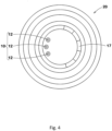
- FIG. 4 is a plan view of a mixing device 20 of a second embodiment.
- the same components as those in the above-described embodiment are designated by the same reference characters, and the description thereof is omitted.
- the flow path 12 of the second inlet 10 may, for example be provided radially inward of the breaking portion 17 in a plan view. Since such a second inlet 10 is located radially inward of the mouth portion 5a (shown in FIG. 1 ) of the container 5, the puncture repair liquid R in the container 5 can be efficiently supplied to the mixing chamber 8.
- FIG. 5 is a partial cross-sectional perspective view of a mixing device 30 of a third embodiment.
- the same components as those in the above-described embodiments are designated by the same reference characters, and the description thereof is omitted.
- the mixing device 30 of the third embodiment includes a second inlet 31 for supplying the puncture repair liquid R to the mixing chamber 8.
- the second inlet 31 has at least one flow path 32, in the third embodiment, one flow path 32.
- the flow path 32 of the third embodiment is a slit having a transverse cross-section having a longitudinal direction. Such a second inlet 31 can inhibit the flow path 32 from being clogged even if rubber lumps are generated in the puncture repair liquid R in the container 5, thereby allowing the puncture repair liquid R to be efficiently supplied.
- the flow path 32 of the third embodiment allows the puncture repair liquid R to be supplied from the slit even when the viscosity of the puncture repair liquid R increases under low temperature conditions.
- the flow path 32 of the second inlet 31 of the third embodiment includes a first portion 32a which is open at the mixing chamber 8, a second portion 32b upstream of the first portion 32a, and at least one step portion 32c between the first portion 32a and the second portion 32b.
- a second flow path cross-sectional area S2 of the second portion 32b is preferably larger than a first flow path cross-sectional area S1 of the first portion 32a.
- a width W 1 in a direction orthogonal to the longitudinal direction of the first portion 32a of the slit is preferably 0.3 to 1.0 mm.
- the width W1 of the first portion 32a is 0.3 mm or more, processing is easy, so that such a slit serves to reduce the production cost.
- the width W1 of the first portion 32a is 1.0 mm or less, such a slit serves to cause a pressure loss in the flow path 32.
- a width W2 in the direction orthogonal to the longitudinal direction of the second portion 32b of the slit is preferably 1.0 to 1.5 mm.
- the width W2 of the second portion 32b is 1.0 mm or more, such a slit serves to cause a pressure loss in the flow path 32.
- the width W2 of the second portion 32b is 1.5 mm or less, such a slit can inhibit the puncture repair liquid R from remaining at the step portion 32c, thereby allowing the puncture repair liquid R to be efficiently supplied.
- the slit which is the flow path 32 of the third embodiment extends linearly. It is easy to process such a flow path 32, so that the production cost can be reduced.
- FIG. 6 is a plan view of a mixing device 40 of a fourth embodiment.
- the same components as those in the above-described embodiments are designated by the same reference characters, and the description thereof is omitted.
- the mixing device 40 of the fourth embodiment includes a second inlet 41 for supplying the puncture repair liquid R to the mixing chamber 8 (shown in FIG. 5 ).
- the second inlet 41 of the fourth embodiment has one flow path 42. Similar to the above-described flow path 32, the flow path 42 of the fourth embodiment is a slit having a transverse cross-section having a longitudinal direction. It is easy to process such a second inlet 41, so that the production cost can be reduced.
- the slit which is the flow path 42 of the fourth embodiment extends in a curved shape.
- Such a second inlet 41 allows the puncture repair liquid R to be supplied to the vicinity of the side surface 8c (shown in FIG. 1 ) of the mixing chamber 8, resulting in excellent dispersibility of the puncture repair liquid R in the mixing chamber 8, and serves to efficiently produce the mixture.
- FIG. 7 is a plan view of a mixing device 50 of a fifth embodiment.
- the mixing device 50 of the fifth embodiment includes a second inlet 51 for supplying the puncture repair liquid R to the mixing chamber 8 (shown in FIG. 5 ).
- Test mixing devices having the basic structure shown in FIG. 1 to FIG. 3 were produced as test mixing devices on the basis of specifications in Table 1. Using the produced test mixing devices, puncture repair liquid supply performance was tested.
- the test method for supply performance is as follows.
- Each produced test mixing device was attached to a container containing a puncture repair liquid and connected to a compressor, and the supply amount of the puncture repair liquid per unit time when a mixture was discharged was obtained as an average value obtained when 100 measurements were made.
- the results are indicated as indexes with the result of a comparative example being regarded as 100.
- a lower value means that the supply of the puncture repair liquid is gentle and the risk of remaining of the puncture repair liquid is reduced.
- the mixing device of each Example has a gentle supply amount of the puncture repair liquid per unit time as compared to the comparative example, thereby reducing the risk of the puncture repair liquid remaining in the mixing chamber and the outlet and allowing a punctured object to be efficiently repaired.
- the present invention is as follows.
- a mixing device for mixing a puncture repair liquid and compressed air including:
- a flow path length of the first portion is 10% to 70% of a total length of the flow path.
- a bottle unit including:
- a puncture repair kit including:
Landscapes
- Engineering & Computer Science (AREA)
- Mechanical Engineering (AREA)
Abstract
Description
- The present invention relates to a mixing device for mixing a puncture repair liquid and compressed air, a bottle unit including the mixing device, and a puncture repair kit including the bottle unit.
- Hitherto, a puncture repair kit for repairing an object such as a punctured tire has been known. For example,
Japanese Laid-Open Patent Publication No. 2017-056662 - However, with the puncture repair kit of
Japanese Laid-Open Patent Publication No. 2017-056662 - The present invention has been made in view of the above circumstances, and a main object of the present invention is to provide a mixing device, a bottle unit, and a puncture repair kit that allow a punctured object to be efficiently repaired.
- The present invention is directed to a mixing device for mixing a puncture repair liquid and compressed air, the mixing device including: a mixing chamber having a space for mixing the puncture repair liquid and the compressed air; a first inlet for supplying the compressed air to the mixing chamber; a second inlet for supplying the puncture repair liquid to the mixing chamber; and an outlet for discharging a mixture of the puncture repair liquid and the compressed air from the mixing chamber, wherein the second inlet includes a flow path including a first portion which is open at the mixing chamber and a second portion upstream of the first portion, the first portion has a first flow path cross-sectional area, the second portion has a second flow path cross-sectional area larger than the first flow path cross-sectional area, and the flow path includes a step portion which is between the first portion and the second portion and discontinuously changes a flow path cross-sectional area thereof.
- As a result of having the above-described configuration, the mixing device of the present invention allows a punctured object to be efficiently repaired.
-
-
FIG. 1 is a cross-sectional view showing one embodiment of a puncture repair kit of the present invention; -
FIG. 2 is a partial cross-sectional perspective view of a mixing device; -
FIG. 3 is a plan view of the mixing device; -
FIG. 4 is a plan view of a mixing device of a second embodiment; -
FIG. 5 is a partial cross-sectional perspective view of a mixing device of a third embodiment; -
FIG. 6 is a plan view of a mixing device of a fourth embodiment; and -
FIG. 7 is a plan view of a mixing device of a fifth embodiment. - Hereinafter, an embodiment of the present invention will be described in detail with reference to the drawings.
-
FIG. 1 is a cross-sectional view showing a puncture repair kit 1 of the present embodiment. As shown inFIG. 1 , the puncture repair kit 1 is suitably used, for example, for filling an object T, such as a punctured tire, with a puncture repair liquid R and compressed air A. - The puncture repair kit 1 of the present embodiment includes a
bottle unit 2 for discharging a mixture of the puncture repair liquid R and the compressed air A to the object T, and acompressor 3 for supplying the compressed air A. Thebottle unit 2 of the present embodiment includes amixing device 4 for mixing the puncture repair liquid R and the compressed air A, and acontainer 5 for containing the puncture repair liquid R. Themixing device 4 includes, for example, an adapter member 6 attached to thecontainer 5 and a cap member 7 attached to the adapter member 6. - In such a
bottle unit 2, it is easy to attach themixing device 4 and thecontainer 5 to each other, so that thebottle unit 2 serves to shorten the time required for puncture repair. In addition, themixing device 4 can mix the puncture repair liquid R and the compressed air A in advance before filling the object T, thereby shortening the time required for puncture repair. Themixing device 4 is not limited to such a mode, and may be, for example, an integrally molded product in which the adapter member 6 and the cap member 7 are integrated. - The
container 5 has, for example, amouth portion 5a for containing the puncture repair liquid R inside thecontainer 5. Thecontainer 5 contains the puncture repair liquid R therein, for example, through themouth portion 5a. Themouth portion 5a has, for example, a film (not shown) for holding the contained puncture repair liquid R in an airtight manner. - The
mixing device 4 is preferably attached to themouth portion 5a of thecontainer 5. Such acontainer 5 eliminates the need to form a separate outlet for the puncture repair liquid R and serves to reduce the production cost. - The
mixing device 4 of the present embodiment includes amixing chamber 8 having a space for mixing the puncture repair liquid R and the compressed air A. Themixing chamber 8 includes, for example, atop surface 8a which is located on an upper side when in use in which themixing device 4 is attached to thecontainer 5 and puncture repair is performed, afloor surface 8b which is located on a lower side when in use, and aside surface 8c connecting thetop surface 8a and thefloor surface 8b. Themixing chamber 8 has, for example, a space having a circular column shape in which thetop surface 8a and thefloor surface 8b are circular. - The
mixing device 4 of the present embodiment includes afirst inlet 9 for supplying the compressed air A to themixing chamber 8, and asecond inlet 10 for supplying the puncture repair liquid R to themixing chamber 8. Thefirst inlet 9 communicates, for example, with thecompressor 3 which is a compressed air source. Thesecond inlet 10 communicates, for example, with thecontainer 5 containing the puncture repair liquid R. - In such a
mixing device 4, themixing chamber 8 can be repeatedly brought into a positive pressure state and a negative pressure state by pulsation of the compressed air A supplied from thecompressor 3, thereby dripping the puncture repair liquid R in thecontainer 5 from thesecond inlet 10 into themixing chamber 8 to produce a mixture. - The
mixing device 4 preferably includes anoutlet 11 for discharging the mixture of the puncture repair liquid R and the compressed air A from themixing chamber 8. Such amixing device 4 allows the mixture of the puncture repair liquid R and the compressed air A to be supplied to the object T, so that the time required for puncture repair can be reduced as compared to the case of sequentially supplying the puncture repair liquid R and the compressed air A. - The
first inlet 9 and theoutlet 11 are provided, for example, in the cap member 7. Thefirst inlet 9 and theoutlet 11 of the present embodiment are provided in thefloor surface 8b. Thesecond inlet 10 is provided, for example, in aseparation wall 6a of the adapter member 6. Thesecond inlet 10 of the present embodiment is provided in thetop surface 8a. - Such a
mixing device 4 discharges the mixture of the compressed air A and the puncture repair liquid R dripped from thesecond inlet 10 located on the upper side, through theoutlet 11 located on the lower side, and thus can inhibit the dripped puncture repair liquid R from remaining therein, thereby efficiently producing the mixture. - Even with the
mixing device 4 in which theoutlet 11 is located on the lower side, if the supply amount of the puncture repair liquid R dripped from thesecond inlet 10 is excessive, the risk of the puncture repair liquid R remaining in themixing chamber 8 and theoutlet 11 increases. Such remaining of the puncture repair liquid R can cause clogging and hinder efficient repair of the punctured object T. - In general, the supply of the puncture repair liquid R can be made gentle by reducing the flow path cross-sectional area of the
second inlet 10. On the other hand, forming thesecond inlet 10 so as to have a small flow path cross-sectional area makes processing difficult, which may increase the production cost, and the risk of the puncture repair liquid R remaining in thesecond inlet 10 also increases. -
FIG. 2 is a partial cross-sectional perspective view of themixing device 4. As shown inFIG. 2 , thesecond inlet 10 of the present embodiment includes aflow path 12 including afirst portion 12a which is open at themixing chamber 8 and asecond portion 12b upstream of thefirst portion 12a. Thefirst portion 12a has, for example, a first flow path cross-sectional area S1. Thesecond portion 12b preferably has a second flow path cross-sectional area S2 larger than the first flow path cross-sectional area S1. It is easy to process such asecond inlet 10, so that the production cost can be reduced. - The
flow path 12 of the present embodiment includes astep portion 12c which is between thefirst portion 12a and thesecond portion 12b and discontinuously changes a flow path cross-sectional area thereof. Such aflow path 12 can reduce the flow rate of the puncture repair liquid R by causing a pressure loss in theflow path 12, thereby making the supply of the puncture repair liquid R gentle. - Accordingly, the
second inlet 10 can optimize the supply amount of the puncture repair liquid R to themixing chamber 8 per unit time, thereby inhibiting the puncture repair liquid R from being excessively supplied to themixing chamber 8 and inhibiting the dripped puncture repair liquid R from remaining. Therefore, themixing device 4 of the present embodiment allows the punctured object T to be efficiently repaired. - As a more preferable mode, the
first portion 12a extends with the first flow path cross-sectional area S1 being constant. Thesecond portion 12b preferably extends with the second flow path cross-sectional area S2 being constant. It is easy to process such asecond inlet 10, so that the production cost can be reduced. - The second flow path cross-sectional area S2 is preferably 150% to 300% of the first flow path cross-sectional area S1. When the second flow path cross-sectional area S2 is 150% or more of the first flow path cross-sectional area S1, a pressure loss can be assuredly caused in the
flow path 12. When the second flow path cross-sectional area S2 is 300% or less of the first flow path cross-sectional area S1, the puncture repair liquid R can be inhibited from remaining at thestep portion 12c, thereby allowing the puncture repair liquid R to be efficiently supplied. From such a viewpoint, the second flow path cross-sectional area S2 is more preferably 180% to 200% of the first flow path cross-sectional area S1. - An angle θ between the outer circumferential surface of the
second portion 12b and a step surface of thestep portion 12c is preferably 30 to 140°. When the angle θ between thesecond portion 12b and thestep portion 12c is 30° or more, the flow rate of the puncture repair liquid R can be reduced while the puncture repair liquid R is inhibited from remaining at thestep portion 12c. When the angle θ between thesecond portion 12b and thestep portion 12c is 140° or less, a pressure loss can be assuredly caused in theflow path 12. From such a viewpoint, the angle θ between thesecond portion 12b and thestep portion 12c is more preferably 45 to 100°. - A flow path length L 1 of the
first portion 12a is preferably 10% to 70% of a total length La of theflow path 12. When the flow path length L1 of thefirst portion 12a is 10% or more of the total length La of theflow path 12, a pressure loss can be caused in thefirst portion 12a, so that the flow rate of the puncture repair liquid R at thefirst portion 12a can be reduced. When the flow path length L1 of thefirst portion 12a is 70% or less of the total length La of theflow path 12, a pressure loss can be assuredly caused at thestep portion 12c. From such a viewpoint, the flow path length L1 of thefirst portion 12a is more preferably 20% to 40% of the total length La of theflow path 12. - The
flow path 12 may include, for example, a third portion (not shown), upstream of thesecond portion 12b, which has a flow path cross-sectional area larger than the second flow path cross-sectional area S2, and the flow path cross-sectional area thereof may change in more steps. In addition, in themixing device 4, for example, a second separation wall (not shown) may be provided upstream of theseparation wall 6a to form thesecond inlet 10 with multiple steps. -
FIG. 3 is a plan view of themixing device 4. As shown inFIG. 2 andFIG. 3 , thesecond inlet 10 has a plurality offlow paths 12, in the present embodiment, threeflow paths 12. Eachflow path 12 preferably has a circular transverse cross-section. It is easy to process such asecond inlet 10, so that the production cost can be reduced. - A maximum inner diameter ϕ1 of the
first portion 12a is preferably 0.5 to 1.0 mm. When the maximum inner diameter ϕ1 of thefirst portion 12a is 0.5 mm or more, processing is easy, so that such afirst portion 12a serves to reduce the production cost. When the maximum inner diameter ϕ1 of thefirst portion 12a is 1.0 mm or less, such afirst portion 12a serves to cause a pressure loss in theflow path 12. - A maximum inner diameter ϕ2 of the
second portion 12b is preferably 1.0 to 3.0 mm. When the maximum inner diameter ϕ2 of thesecond portion 12b is 1.0 mm or more, such asecond portion 12b serves to cause a pressure loss in theflow path 12. When the maximum inner diameter ϕ2 of thesecond portion 12b is 3.0 mm or less, the puncture repair liquid R can be inhibited from remaining at thestep portion 12c, thereby allowing the puncture repair liquid R to be efficiently supplied. - As shown in
FIG. 1 , the mixingchamber 8 may include, for example, aprotrusion portion 13 which protrudes from thetop surface 8a toward the interior of the mixingchamber 8. For example, a conical shape having a most protruding vertex is suitably adopted for theprotrusion portion 13. Such aprotrusion portion 13 can provide directivity to the flow inside the mixingchamber 8, thereby allowing the mixture of the puncture repair liquid R and the compressed air A to be efficiently discharged. - The mixing
chamber 8 may have, for example, a plurality ofhemispherical recesses 14 formed on at least one of thetop surface 8a, thefloor surface 8b, and theside surface 8c. Such a plurality ofrecesses 14 serve to make the flow smooth and shorten the residence time of the mixture in the mixingchamber 8. - The adapter member 6 is screwed to both the
mouth portion 5a of thecontainer 5 and the cap member 7, for example. The space between the adapter member 6 and themouth portion 5a is preferably sealed by a sealingmember 15. The space between the adapter member 6 and the cap member 7 is sealed, for example, by asub sealing member 16. Such an adapter member 6 is easily attached to thecontainer 5 and to the cap member 7, and has excellent airtightness after being attached. - As shown in
FIG. 1 andFIG. 3 , the adapter member 6 has, for example, a breakingportion 17 which breaks the film (not shown) of themouth portion 5a when the adapter member 6 is attached to themouth portion 5a of thecontainer 5. The breakingportion 17 is preferably provided in an arc shape in a plan view. Such a breakingportion 17 can break the film of themouth portion 5a when themixing device 4 is attached to thecontainer 5, thereby allowing the puncture repair liquid R to be supplied to the mixingchamber 8. - The
flow path 12 of thesecond inlet 10 of the present embodiment is provided on the same circumference as the breakingportion 17 in a plan view. Such asecond inlet 10 allows the puncture repair liquid R to be supplied to the vicinity of theside surface 8c of the mixingchamber 8, resulting in excellent dispersibility of the puncture repair liquid R in the mixingchamber 8, and serves to efficiently produce the mixture. -
FIG. 4 is a plan view of amixing device 20 of a second embodiment. The same components as those in the above-described embodiment are designated by the same reference characters, and the description thereof is omitted. As shown inFIG. 4 , theflow path 12 of thesecond inlet 10 may, for example be provided radially inward of the breakingportion 17 in a plan view. Since such asecond inlet 10 is located radially inward of themouth portion 5a (shown inFIG. 1 ) of thecontainer 5, the puncture repair liquid R in thecontainer 5 can be efficiently supplied to the mixingchamber 8. -
FIG. 5 is a partial cross-sectional perspective view of amixing device 30 of a third embodiment. The same components as those in the above-described embodiments are designated by the same reference characters, and the description thereof is omitted. As shown inFIG. 5 , similar to the above-describedmixing device 4, the mixingdevice 30 of the third embodiment includes asecond inlet 31 for supplying the puncture repair liquid R to the mixingchamber 8. - The
second inlet 31 has at least oneflow path 32, in the third embodiment, oneflow path 32. Theflow path 32 of the third embodiment is a slit having a transverse cross-section having a longitudinal direction. Such asecond inlet 31 can inhibit theflow path 32 from being clogged even if rubber lumps are generated in the puncture repair liquid R in thecontainer 5, thereby allowing the puncture repair liquid R to be efficiently supplied. In addition, theflow path 32 of the third embodiment allows the puncture repair liquid R to be supplied from the slit even when the viscosity of the puncture repair liquid R increases under low temperature conditions. - Similar to the above-described
flow path 12, theflow path 32 of thesecond inlet 31 of the third embodiment includes afirst portion 32a which is open at the mixingchamber 8, asecond portion 32b upstream of thefirst portion 32a, and at least onestep portion 32c between thefirst portion 32a and thesecond portion 32b. Similar to the above-describedsecond portion 12b, a second flow path cross-sectional area S2 of thesecond portion 32b is preferably larger than a first flow path cross-sectional area S1 of thefirst portion 32a. - A width W 1 in a direction orthogonal to the longitudinal direction of the
first portion 32a of the slit is preferably 0.3 to 1.0 mm. When the width W1 of thefirst portion 32a is 0.3 mm or more, processing is easy, so that such a slit serves to reduce the production cost. When the width W1 of thefirst portion 32a is 1.0 mm or less, such a slit serves to cause a pressure loss in theflow path 32. - A width W2 in the direction orthogonal to the longitudinal direction of the
second portion 32b of the slit is preferably 1.0 to 1.5 mm. When the width W2 of thesecond portion 32b is 1.0 mm or more, such a slit serves to cause a pressure loss in theflow path 32. When the width W2 of thesecond portion 32b is 1.5 mm or less, such a slit can inhibit the puncture repair liquid R from remaining at thestep portion 32c, thereby allowing the puncture repair liquid R to be efficiently supplied. - The slit which is the
flow path 32 of the third embodiment extends linearly. It is easy to process such aflow path 32, so that the production cost can be reduced. -
FIG. 6 is a plan view of amixing device 40 of a fourth embodiment. The same components as those in the above-described embodiments are designated by the same reference characters, and the description thereof is omitted. As shown inFIG. 6 , similar to the above-describedmixing device 30, the mixingdevice 40 of the fourth embodiment includes asecond inlet 41 for supplying the puncture repair liquid R to the mixing chamber 8 (shown inFIG. 5 ). - Similar to the above-described
second inlet 31, thesecond inlet 41 of the fourth embodiment has oneflow path 42. Similar to the above-describedflow path 32, theflow path 42 of the fourth embodiment is a slit having a transverse cross-section having a longitudinal direction. It is easy to process such asecond inlet 41, so that the production cost can be reduced. - The slit which is the
flow path 42 of the fourth embodiment extends in a curved shape. Such asecond inlet 41 allows the puncture repair liquid R to be supplied to the vicinity of theside surface 8c (shown inFIG. 1 ) of the mixingchamber 8, resulting in excellent dispersibility of the puncture repair liquid R in the mixingchamber 8, and serves to efficiently produce the mixture. -
FIG. 7 is a plan view of amixing device 50 of a fifth embodiment. The same components as those in the above-described embodiments are designated by the same reference characters, and the description thereof is omitted. As shown inFIG. 7 , similar to the above-describedmixing device 40, the mixingdevice 50 of the fifth embodiment includes asecond inlet 51 for supplying the puncture repair liquid R to the mixing chamber 8 (shown inFIG. 5 ). - The
second inlet 51 has a plurality offlow paths 52, in the fifth embodiment, threeflow paths 52. Similar to the above-describedflow path 42, eachflow path 52 of the fifth embodiment is a slit having a transverse cross-section having a longitudinal direction. It is easy to process such asecond inlet 51, so that the production cost can be reduced. - The slit which is each
flow path 52 of the fifth embodiment extends in a curved shape. Such asecond inlet 51 allows the puncture repair liquid R to be supplied to the vicinity of theside surface 8c (shown inFIG. 1 ) of the mixingchamber 8, resulting in excellent dispersibility of the puncture repair liquid R in the mixingchamber 8, and serves to efficiently produce the mixture. - Although the particularly preferred embodiments of the present invention have been described in detail above, the present invention is not limited to the above-described embodiments, and various modifications can be made to implement the present invention.
- Mixing devices having the basic structure shown in
FIG. 1 to FIG. 3 were produced as test mixing devices on the basis of specifications in Table 1. Using the produced test mixing devices, puncture repair liquid supply performance was tested. The test method for supply performance is as follows. - Each produced test mixing device was attached to a container containing a puncture repair liquid and connected to a compressor, and the supply amount of the puncture repair liquid per unit time when a mixture was discharged was obtained as an average value obtained when 100 measurements were made. The results are indicated as indexes with the result of a comparative example being regarded as 100. A lower value means that the supply of the puncture repair liquid is gentle and the risk of remaining of the puncture repair liquid is reduced.
-
[Table 1] Comp. Ex. Ex. 1 Ex. 2 Ex. 3 Ex. 4 Maximum inner diameter ϕ1 of first portion (mm) 0.8 0.8 0.8 0.8 0.8 Maximum inner diameter ϕ2 of second portion (mm) - 1.5 2.0 1.5 1.5 Flow path length L1 of first portion/ total length La of flow path (%) 100 30 30 15 45 Supply performance (index) 100 60 93 66 90 - As a result of the test, it is confirmed that the mixing device of each Example has a gentle supply amount of the puncture repair liquid per unit time as compared to the comparative example, thereby reducing the risk of the puncture repair liquid remaining in the mixing chamber and the outlet and allowing a punctured object to be efficiently repaired.
- The present invention is as follows.
- A mixing device for mixing a puncture repair liquid and compressed air, the mixing device including:
- a mixing chamber having a space for mixing the puncture repair liquid and the compressed air;
- a first inlet for supplying the compressed air to the mixing chamber;
- a second inlet for supplying the puncture repair liquid to the mixing chamber; and
- an outlet for discharging a mixture of the puncture repair liquid and the compressed air from the mixing chamber, wherein
- the second inlet includes a flow path including a first portion which is open at the mixing chamber and a second portion upstream of the first portion,
- the first portion has a first flow path cross-sectional area,
- the second portion has a second flow path cross-sectional area larger than the first flow path cross-sectional area, and
- the flow path includes a step portion which is between the first portion and the second portion and discontinuously changes a flow path cross-sectional area thereof.
- The mixing device according to Present Invention 1, wherein
- the first portion extends with the first flow path cross-sectional area being constant, and
- the second portion extends with the second flow path cross-sectional area being constant.
- The mixing device according to
Present Invention 1 or 2, wherein the second flow path cross-sectional area is 150% to 300% of the first flow path cross-sectional area. - The mixing device according to any one of Present Inventions 1 to 3, wherein the flow path has a circular transverse cross-section.
- The mixing device according to
Present Invention 4, wherein - a maximum inner diameter (ϕ1) of the first portion is 0.5 to 1.0 mm, and
- a maximum inner diameter (ϕ2) of the second portion is 1.0 to 3.0 mm.
- The mixing device according to any one of Present Inventions 1 to 3, wherein the flow path is a slit having a transverse cross-section having a longitudinal direction.
- The mixing device according to Present Invention 6, wherein the slit extends linearly.
- The mixing device according to Present Invention 6, wherein the slit extends in a curved shape.
- The mixing device according to any one of Present Inventions 6 to 8, wherein
- a width in a direction orthogonal to the longitudinal direction of the first portion of the slit is 0.3 to 1.0 mm, and
- a width in the direction orthogonal to the longitudinal direction of the second portion of the slit is 1.0 to 1.5 mm.
- The mixing device according to any one of Present Inventions 1 to 9, wherein a flow path length of the first portion is 10% to 70% of a total length of the flow path.
- A bottle unit including:
- the mixing device according to any one of Present Inventions 1 to 10; and
- a container containing the puncture repair liquid, wherein
- the container has a mouth portion for containing the puncture repair liquid inside the container, and
- the mixing device is attached to the mouth portion.
- A puncture repair kit including:
- the bottle unit according to
Present Invention 11; and - a compressor for supplying the compressed air.
Claims (12)
- A mixing device (4, 20, 30, 40, 50) for mixing a puncture repair liquid (R) and compressed air (A), the mixing device (4, 20, 30, 40, 50) comprising:a mixing chamber (8) having a space for mixing the puncture repair liquid (R) and the compressed air (A);a first inlet (9) for supplying the compressed air (A) to the mixing chamber (8);a second inlet (10, 31, 41, 51) for supplying the puncture repair liquid (R) to the mixing chamber (8); andan outlet (11) for discharging a mixture of the puncture repair liquid (R) and the compressed air (A) from the mixing chamber (8), whereinthe second inlet (10, 31, 41, 51) includes a flow path (12, 32, 42, 52) including a first portion (12a, 32a) which is open at the mixing chamber (8) and a second portion (12b, 32b) upstream of the first portion (12a, 32a),the first portion (12a, 32a) has a first flow path cross-sectional area (S1),the second portion (12b, 32b) has a second flow path cross-sectional area (S2) larger than the first flow path cross-sectional area (S1), andthe flow path (12, 32, 42, 52) includes a step portion (12c, 32c) which is between the first portion (12a, 32a) and the second portion (12b, 32b) and discontinuously changes a flow path cross-sectional area thereof.
- The mixing device (4) according to claim 1, whereinthe first portion (12a) extends with the first flow path cross-sectional area (S1) being constant, andthe second portion (12b) extends with the second flow path cross-sectional area (S2) being constant.
- The mixing device (4) according to claim 1 or 2, wherein the second flow path cross-sectional area (S2) is 150% to 300% of the first flow path cross-sectional area (S1).
- The mixing device (4) according to any one of claims 1 to 3, wherein the flow path (12) has a circular transverse cross-section.
- The mixing device (4) according to claim 4, whereina maximum inner diameter (ϕ1) of the first portion (12a) is 0.5 to 1.0 mm, anda maximum inner diameter (ϕ2) of the second portion (12b) is 1.0 to 3.0 mm.
- The mixing device (30, 40, 50) according to any one of claims 1 to 3, wherein the flow path (32, 42, 52) is a slit having a transverse cross-section having a longitudinal direction.
- The mixing device (30) according to claim 6, wherein the slit extends linearly.
- The mixing device (40, 50) according to claim 6, wherein the slit extends in a curved shape.
- The mixing device (30) according to any one of claims 6 to 8, whereina width (W1) in a direction orthogonal to the longitudinal direction of the first portion (32a) of the slit is 0.3 to 1.0 mm, anda width (W2) in the direction orthogonal to the longitudinal direction of the second portion (32b) of the slit is 1.0 to 1.5 mm.
- The mixing device (4) according to any one of claims 1 to 9, wherein a flow path length (L1) of the first portion (12a) is 10% to 70% of a total length (La) of the flow path (12).
- A bottle unit (2) comprising:the mixing device (4) according to any one of claims 1 to 10; anda container (5) containing the puncture repair liquid (R), whereinthe container (5) has a mouth portion (5a) for containing the puncture repair liquid (R) inside the container (5), andthe mixing device (4) is attached to the mouth portion (5a).
- A puncture repair kit (1) comprising:the bottle unit (2) according to claim 11; anda compressor (3) for supplying the compressed air (A).
Applications Claiming Priority (1)
| Application Number | Priority Date | Filing Date | Title |
|---|---|---|---|
| JP2023161552A JP2025052702A (en) | 2023-09-25 | 2023-09-25 | Mixing device, bottle unit and puncture repair kit |
Publications (1)
| Publication Number | Publication Date |
|---|---|
| EP4527603A1 true EP4527603A1 (en) | 2025-03-26 |
Family
ID=92108425
Family Applications (1)
| Application Number | Title | Priority Date | Filing Date |
|---|---|---|---|
| EP24191508.1A Pending EP4527603A1 (en) | 2023-09-25 | 2024-07-29 | Mixing device, bottle unit, and puncture repair kit |
Country Status (3)
| Country | Link |
|---|---|
| EP (1) | EP4527603A1 (en) |
| JP (1) | JP2025052702A (en) |
| CN (1) | CN119682267A (en) |
Citations (4)
| Publication number | Priority date | Publication date | Assignee | Title |
|---|---|---|---|---|
| DE3418328A1 (en) * | 1984-05-17 | 1985-11-21 | E. & M. Lamort S.A., Vitry-le-François, Marne | Apparatus for aeration |
| JP2017056662A (en) | 2015-09-17 | 2017-03-23 | 住友ゴム工業株式会社 | Puncture repair kit |
| WO2019111633A1 (en) * | 2017-12-05 | 2019-06-13 | 大陽日酸株式会社 | Flow type reaction device |
| DE102018219038A1 (en) * | 2018-11-08 | 2020-05-14 | Continental Reifen Deutschland Gmbh | Distribution device for producing an aerosol, system for sealing and inflating pneumatic vehicle tires and a method for sealing pneumatic vehicle tires or inflatable technical rubber articles, and the use of a metering unit for producing an aerosol |
-
2023
- 2023-09-25 JP JP2023161552A patent/JP2025052702A/en active Pending
-
2024
- 2024-07-29 CN CN202411020076.0A patent/CN119682267A/en active Pending
- 2024-07-29 EP EP24191508.1A patent/EP4527603A1/en active Pending
Patent Citations (4)
| Publication number | Priority date | Publication date | Assignee | Title |
|---|---|---|---|---|
| DE3418328A1 (en) * | 1984-05-17 | 1985-11-21 | E. & M. Lamort S.A., Vitry-le-François, Marne | Apparatus for aeration |
| JP2017056662A (en) | 2015-09-17 | 2017-03-23 | 住友ゴム工業株式会社 | Puncture repair kit |
| WO2019111633A1 (en) * | 2017-12-05 | 2019-06-13 | 大陽日酸株式会社 | Flow type reaction device |
| DE102018219038A1 (en) * | 2018-11-08 | 2020-05-14 | Continental Reifen Deutschland Gmbh | Distribution device for producing an aerosol, system for sealing and inflating pneumatic vehicle tires and a method for sealing pneumatic vehicle tires or inflatable technical rubber articles, and the use of a metering unit for producing an aerosol |
Also Published As
| Publication number | Publication date |
|---|---|
| JP2025052702A (en) | 2025-04-07 |
| CN119682267A (en) | 2025-03-25 |
Similar Documents
| Publication | Publication Date | Title |
|---|---|---|
| KR950009536B1 (en) | A mixing chamber for mixing a gaseous and a liquid component | |
| CN101316696B (en) | Sealing inflating device | |
| US12145331B2 (en) | Distributor device, system, and method for sealing and using a metering unit | |
| US20100071801A1 (en) | Tire sealant liquid container | |
| EP1566424B1 (en) | Puncture-sealing agent | |
| US12070916B2 (en) | Mixing device, bottle unit, and puncture repair kit | |
| US8757865B2 (en) | Foodstuff conveyor apparatus and method of conveying a foodstuff | |
| EP4527604A1 (en) | Mixing device, bottle unit, and puncture repair kit | |
| JP7631497B2 (en) | Sealant bottle | |
| CN112424080B (en) | Foam sprayer | |
| US12365154B2 (en) | Mixing device, bottle unit, and puncture repair kit | |
| EP3889065A1 (en) | Discharge container | |
| EP3747601A1 (en) | Machining apparatus and machining method | |
| JP2025052702A (en) | Mixing device, bottle unit and puncture repair kit | |
| TWI827820B (en) | Biological adhesive application equipment | |
| EP4438166A1 (en) | Mixing device, bottle unit, and puncture repair kit | |
| EP4438165A1 (en) | Mixing device, bottle unit, and puncture repair kit | |
| CN102818113A (en) | Gas tank pneumatic device having angled gas distribution device | |
| EP4438279B1 (en) | Bottle set and puncture repair kit | |
| EP4628290A1 (en) | Sealant bottle and method for repairing tire | |
| JP2023066212A (en) | puncture repair unit and puncture repair kit | |
| JPH09221103A (en) | Nozzle for filling viscous substance | |
| WO2025069145A1 (en) | Puncture repair kit, mixing device, puncture repair method, and mixing method | |
| CN222659108U (en) | Glue spraying device and glue spraying gun | |
| US10143217B2 (en) | Air inlet arrangement for ice cream or yogurt machine |
Legal Events
| Date | Code | Title | Description |
|---|---|---|---|
| PUAI | Public reference made under article 153(3) epc to a published international application that has entered the european phase |
Free format text: ORIGINAL CODE: 0009012 |
|
| STAA | Information on the status of an ep patent application or granted ep patent |
Free format text: STATUS: THE APPLICATION HAS BEEN PUBLISHED |
|
| AK | Designated contracting states |
Kind code of ref document: A1 Designated state(s): AL AT BE BG CH CY CZ DE DK EE ES FI FR GB GR HR HU IE IS IT LI LT LU LV MC ME MK MT NL NO PL PT RO RS SE SI SK SM TR |
|
| STAA | Information on the status of an ep patent application or granted ep patent |
Free format text: STATUS: REQUEST FOR EXAMINATION WAS MADE |
|
| 17P | Request for examination filed |
Effective date: 20250819 |
|
| P01 | Opt-out of the competence of the unified patent court (upc) registered |
Free format text: CASE NUMBER: UPC_APP_0005135_4527603/2026 Effective date: 20260212 |