EP4527551A1 - Sander - Google Patents
Sander Download PDFInfo
- Publication number
- EP4527551A1 EP4527551A1 EP24197785.9A EP24197785A EP4527551A1 EP 4527551 A1 EP4527551 A1 EP 4527551A1 EP 24197785 A EP24197785 A EP 24197785A EP 4527551 A1 EP4527551 A1 EP 4527551A1
- Authority
- EP
- European Patent Office
- Prior art keywords
- light
- dust
- housing
- sander
- emitting portion
- Prior art date
- Legal status (The legal status is an assumption and is not a legal conclusion. Google has not performed a legal analysis and makes no representation as to the accuracy of the status listed.)
- Granted
Links
Images






Classifications
-
- B—PERFORMING OPERATIONS; TRANSPORTING
- B24—GRINDING; POLISHING
- B24B—MACHINES, DEVICES, OR PROCESSES FOR GRINDING OR POLISHING; DRESSING OR CONDITIONING OF ABRADING SURFACES; FEEDING OF GRINDING, POLISHING, OR LAPPING AGENTS
- B24B23/00—Portable grinding machines, e.g. hand-guided; Accessories therefor
-
- B—PERFORMING OPERATIONS; TRANSPORTING
- B25—HAND TOOLS; PORTABLE POWER-DRIVEN TOOLS; MANIPULATORS
- B25F—COMBINATION OR MULTI-PURPOSE TOOLS NOT OTHERWISE PROVIDED FOR; DETAILS OR COMPONENTS OF PORTABLE POWER-DRIVEN TOOLS NOT PARTICULARLY RELATED TO THE OPERATIONS PERFORMED AND NOT OTHERWISE PROVIDED FOR
- B25F5/00—Details or components of portable power-driven tools not particularly related to the operations performed and not otherwise provided for
- B25F5/02—Construction of casings, bodies or handles
-
- B—PERFORMING OPERATIONS; TRANSPORTING
- B25—HAND TOOLS; PORTABLE POWER-DRIVEN TOOLS; MANIPULATORS
- B25F—COMBINATION OR MULTI-PURPOSE TOOLS NOT OTHERWISE PROVIDED FOR; DETAILS OR COMPONENTS OF PORTABLE POWER-DRIVEN TOOLS NOT PARTICULARLY RELATED TO THE OPERATIONS PERFORMED AND NOT OTHERWISE PROVIDED FOR
- B25F5/00—Details or components of portable power-driven tools not particularly related to the operations performed and not otherwise provided for
- B25F5/02—Construction of casings, bodies or handles
- B25F5/021—Construction of casings, bodies or handles with guiding devices
-
- F—MECHANICAL ENGINEERING; LIGHTING; HEATING; WEAPONS; BLASTING
- F21—LIGHTING
- F21V—FUNCTIONAL FEATURES OR DETAILS OF LIGHTING DEVICES OR SYSTEMS THEREOF; STRUCTURAL COMBINATIONS OF LIGHTING DEVICES WITH OTHER ARTICLES, NOT OTHERWISE PROVIDED FOR
- F21V33/00—Structural combinations of lighting devices with other articles, not otherwise provided for
- F21V33/008—Leisure, hobby or sport articles, e.g. toys, games or first-aid kits; Hand tools; Toolboxes
- F21V33/0084—Hand tools; Toolboxes
Definitions
- the present application relates to a power tool, in particular, to a sander.
- a sander in the related art is an electric tool for sanding operations. It is often used to sand uneven or unevenly thick walls, desktops, etc. to obtain a surface with a target smoothness.
- Sanders includes or can be called belt sanders, grinding machine, or polishers.
- Handheld sanders are an important category of sanders. They are widely used in various industries due to their small size and easy portability.
- a sander includes a housing, the housing including a housing top, a housing bottom and a contraction portion arranged between the housing top and the housing bottom; a base plate assembly, including a base plate; a driving assembly, including a motor, the motor being used to drive the base plate; and an illumination device, comprising a light-emitting portion.
- the light-emitting portion is arranged in the housing and located above the contraction portion, and the base plate is within an illumination range of the light-emitting portion.
- the light-emitting portion is arranged at the junction of the contraction portion and the housing top.
- the illumination device is detachably arranged relative to the housing.
- the light-emitting portion is one of or at least two of a point light source, an area light source, and an LED light source.
- the light-emitting part can emit light of at least two colors.
- the illumination device is configured to transmit a control signal to a user terminal to adjust the light-emitting parameters of the light-emitting portion.
- an overall height of the sander is less than or equal to 120 mm.
- a relative term (such as “about”, “approximately”, and “substantially) used in conjunction with quantity or condition includes a stated value and has a meaning dictated by the context.
- the relative term includes at least a degree of error associated with the measurement of a particular value, a tolerance caused by manufacturing, assembly, and use associated with the particular value, and the like.
- Such relative term should also be considered as disclosing the range defined by the absolute values of the two endpoints.
- the relative term may refer to plus or minus of a certain percentage (such as 1%, 5%, 10%, or more) of an indicated value. A value that did not use the relative term should also be disclosed as a particular value with a tolerance.
- “substantially” when expressing a relative angular position relationship may refer to adding or subtracting a certain degree (such as 1 degree, 5 degrees, 10 degrees or more) to the indicated angle.
- a function performed by an assembly may be performed by one assembly, multiple assemblies, one member, or multiple members.
- a function performed by a member may be performed by one member, an assembly, or a combination of members.
- a sander 200 includes a housing 210, a base plate assembly 220, a drive assembly 230, a main switch assembly 240, a dust collection device 251, and an energy source 260.
- the energy source 260 is used for supplying energy to the sander 200.
- the energy source 260 may be alternating current power or direct current power such as the battery pack or another portable mobile power supply.
- the dust collection device 251 may be a dust collection bag or a dust collection box; or the sander 200 may be connected to a vacuum cleaner, and the vacuum cleaner serves as the dust collection device 251.
- the case where the dust collection device 251 is the dust collection box is used as an example so that the dust collection device 251 is in the shape of a box, thereby further enhancing the integrity between the dust collection device 251 and the housing 210.
- the housing 210 and/or the dust collection device 251 are formed with a grip 211 for the user to hold.
- the main switch assembly 240 is disposed on the front side of the housing 210 and the grip 211 so that the user can relatively conveniently trigger the main switch assembly 240 when holding the grip 211.
- An accommodation portion is formed on the rear side of the housing 210 and used for mounting the energy source 260 such as the battery pack.
- the base plate assembly 220 is disposed at the bottom of the housing 210, and the drive assembly 230 is disposed in the housing 210.
- the base plate assembly 220 includes a base plate 223 connected to a work accessory; the drive assembly 230 includes an electric motor 231, and the electric motor 231 is used for driving the base plate 223 so that the base plate 223 and the work accessory swing relative to the housing 210.
- the base plate 223 includes an upper surface and a lower surface that are opposite. The lower surface is used for mounting the work accessory.
- the work accessory may be the functional element such as the sandpaper. When the base plate 223 moves eccentrically, the surface of a workpiece to be sanded can be continuously rubbed with the sandpaper, thereby implementing the function of sanding and polishing the workpiece to be sanded.
- the sander 200 further includes a dust channel 212.
- the dust channel 212 is disposed in the housing 210. Dust is collected from the base plate 223, flows into the dust channel 212, and then flows into the dust collection device 251 through the dust channel 212.
- the base plate 223 is provided with a through hole penetrating the upper surface and the lower surface, and dust enters the dust channel 212 through the through hole.
- the electric motor 231 includes a motor shaft for outputting power, and the motor shaft rotates about a motor axis.
- the motor axis extends basically along the up and down direction.
- the sander 200 further includes an airflow element 234 drivable by the electric motor 231.
- the airflow element 234 is drivable by the electric motor 231 to rotate about the central axis. When rotating, the airflow element 234 can generate the airflow, and the airflow drives dust such that the dust is collected from the base plate 223, flows into the dust channel 212, and then flows into the dust collection device 251 through the dust channel 212.
- the housing 210 is further provided with a control panel 232 and a speed regulation assembly 233.
- the control panel 232 is electrically connected to the electric motor 231.
- the speed regulation assembly 233 is electrically connected to the control panel 232.
- the speed regulation assembly 233 can control the rotational speed of the electric motor 231.
- the speed regulation assembly 233 can be controlled by a speed regulation button on the housing 210.
- the dust channel 212 includes a dust inlet 221 and a dust outlet 222.
- the dust channel 212 has an upper sidewall and a lower sidewall along the up and down direction, where the distance from the upper sidewall to the lower sidewall gradually increases along a preset direction of rotation 205. It is to be understood that the sucked dust flows from the dust inlet 221 to the dust outlet 222. In the vertical direction, the dust outlet 222 is higher than the dust inlet 221; the base plate 223 extends in a first plane, and the projection of the dust channel 212 on the first plane is basically arc-shaped so that the resistance to dust flow is reduced and smooth dust collection is achieved. In addition, since the resistance to dust collection is reduced, the energy consumption of the sander is reduced. It is to be noted that the arc shape involved in the present application may be an arc along the internal contour of the housing or may be a curve or another non-circular arc such as an involute.
- the working duration of the sander 200 when the battery pack consumes 10 WH of energy is defined as the functional time T of the sander 200
- the product of the load-free rotational speed N of the electric motor 231 and the functional time T of the sander 200 is greater than or equal to 63000 rpm ⁇ min and less than or equal to 120000 rpm ⁇ min.
- the product of the load-free rotational speed N of the electric motor 231 and the functional time T of the sander 200 is greater than or equal to 70000 rpm ⁇ min and less than or equal to 115000 rpm ⁇ min.
- the product of the load-free rotational speed N of the electric motor 231 and the functional time T of the sander 200 is greater than or equal to 77000 rpm ⁇ min and less than or equal to 110000 rpm ⁇ min.
- the functional time T of the sander 200 is greater than or equal to 7 min and less than or equal to 11 min.
- the dust outlet 222 connects with the dust collection device 251; the higher the dust outlet 222 is, the less likely the dust collection device 251 is blocked by dust.
- the height difference H1 in the vertical direction between the dust outlet 222 and the dust inlet 221 is greater than or equal to 9 mm and less than or equal to 41 mm. In some examples, the height difference H1 in the vertical direction between the dust outlet 222 and the dust inlet 221 is greater than or equal to 15 mm and less than or equal to 30 mm. In some examples, the height difference H1 in the vertical direction between the dust outlet 222 and the dust inlet 221 is 27 mm.
- the included angle formed between a line between the dust inlet 221 and the center point of the base plate 223 and a line between the dust outlet 222 and the center point of the base plate 223 is a first angle ⁇ , and the first angle ⁇ is greater than or equal to 60 degrees and less than or equal to 120 degrees so that the resistance of the airflow in the dust channel 212 is reduced.
- the first angle ⁇ is greater than or equal to 80 degrees and less than or equal to 100 degrees.
- the first angle ⁇ is equal to 60 degrees, 70 degrees, 80 degrees, 90 degrees, 100 degrees, 110 degrees, or 120 degrees.
- the dust inlet 221 and the dust outlet 222 of the dust channel 212 are both located in the housing 210.
- the projection of the dust outlet 222 of the dust channel 212 on the first plane does not extend beyond the boundary range of the base plate 223.
- the base plate 223 is basically rectangular, and the center point of the base plate 223 is the center point of the rectangular surface.
- the dust channel 212 extends in a spiral shape between the dust inlet 221 and the dust outlet 222 so that the dust channel 212 rises gently and the airflow resistance is reduced. In some examples, the dust channel 212 extends in a straight line between the dust inlet 221 and the dust outlet 222.
- the projection of the dust channel 212 on the first plane is a first projection, and the first projection is completely located within the boundary of the base plate 223 so that the structure is compact and the center of gravity is stable.
- the projection of the dust collection device 251 on the first plane is a second projection, and the second projection is completely located within the boundary of the base plate 223 so that the structure is compact and the center of gravity is stable.
- the first projection may overlap the second projection.
- the area of the second projection is greater than half of the area of the base plate 223.
- a first electrostatic conductive assembly is disposed on the dust collection device 251 and used for conducting static electricity from the dust collection device.
- the first electrostatic conductive assembly may be a metal sheet such as a copper sheet.
- the sander 200 further includes a second electrostatic conductive assembly.
- the second electrostatic conductive assembly includes a first conductive member and a second conductive member. Two ends of the first conductive member are separately connected to the dust channel 212 and the stator core of the electric motor 231. Two ends of the second conductive member are separately connected to the stator core and the housing 210. Since the human hand holds the housing 210, the static electricity on the dust channel 212 is conducted by the human hand through the second electrostatic conductive assembly.
- the dust collection device 251 has a dust collection cavity 252, an air inlet 253, and an air outlet 254, where the air inlet 253 and the air outlet 254 connect with the dust collection cavity 252.
- the air inlet 253 connects with the dust outlet 222 of the dust channel 212. Therefore, the dust can enter the dust collection device 251 from the dust channel 212, and the air outlet 254 connects with the outside; after the airflow carrying dust enters the dust collection device 251, the dust falls into the dust collection cavity 252 under the action of the gravity, and the airflow flows out from the air outlet 254.
- the air inlet 253 connects with the dust outlet 222 of the dust channel 212.
- the area of the air inlet 253 is less than or equal to 400 mm 2 , ensuring sufficient intake air volume under the premise of fully utilizing the space. In some examples, the area of the air inlet 253 is less than or equal to 350 mm 2 . In some examples, the area of the air inlet 253 is less than or equal to 300 mm 2 . In some examples, the area of the air inlet 253 is equal to 250 mm 2 , 260 mm 2 , or 270 mm 2 .
- a filter 257 is disposed at the air outlet 254 of the dust collection device 251. If a small amount of dust flows out of the air outlet 254 with the airflow, the filter 257 can filter the dust to prevent the dust from overflowing.
- the filter 257 includes a holder 258 and filter paper 259.
- the filter paper 259 is mounted on the holder 258.
- the holder 258 is detachably connected to the air outlet 254.
- the filter paper 259 is supported by the holder 258.
- the holder 258 is easy to mount and disassemble. When the filter paper 259 is replaced, the holder 258 may be disassembled. After the filter paper 259 is replaced, the holder 258 is mounted again.
- the holder 258 may engage with the dust collection device 251 in a snap-fit manner.
- one air outlet 254 is provided and located at the top of the dust collection device 251.
- the bottom edge of the air inlet 253 is higher than the bottom surface of the dust collection cavity 252, and the height difference H2 between the bottom edge of the air inlet 253 and the bottom surface of the dust collection cavity 252 is greater than or equal to 5 mm and less than or equal to 20 mm so that the dust in the dust collection cavity 252 is prevented from overflowing from the air inlet 253, the air inlet 253 is prevented from being blocked, the dust collection cavity 252 has a certain space, and the dust collection amount is improved.
- At least two air outlets 254 are provided so that air permeability and exhaust air volume are increased, and the dust collection is smoother.
- the air outlets 254 may be disposed on the top or side surface of the dust collection device 251.
- the air outlet 254 is located on a side of the dust collection device 251 facing the housing 210, that is, the air outlet 254 is disposed on the inner side surface of the dust collection device 251 so that the outer surface of the dust collection device 251 is flat.
- Each air outlet 254 is provided with the filter 257, and the filter 257 can filter the dust and prevent the dust from overflowing.
- the housing 210 includes a mounting plate 213.
- the mounting plate 213 has a first mounting surface 231.
- the dust collection device 251 is detachably connected to the first mounting surface 231.
- the first mounting surface 231 is a mirror-finished surface so that the friction during assembly is reduced, thereby facilitating the disassembly and assembly of the dust collection device 251.
- the dust collection device 251 may engage with the housing 210 in a snap-fit manner, specifically, through a ball snap catch 214.
- the ball snap catch 214 is disposed on the first mounting surface 231.
- the dust collection device 251 is pushed to the housing 210 so that the dust collection device 251 slides along the first mounting surface 231 to engage with the ball snap catch 214 in a snap-fit manner. Since the first mounting surface 231 is the mirror-finished surface, the friction during assembly is reduced.
- the dust collection device 251 has the dust collection cavity 252, a cyclone dust collection assembly 256 is disposed in the dust collection cavity 252, the cyclone dust collection assembly 256 has the air inlet 253, a dust exhaust outlet 250, and the air outlet 254, the air inlet 253 connects with the dust outlet 222, the dust exhaust outlet 250 connects with the dust collection cavity 252, and the air outlet 254 connects with the outside. Due to the arrangement of the cyclone dust collection assembly 256, the air inlet 253 does not need to be higher than the bottom surface of the dust collection cavity 252, and the dust in the dust collection cavity 252 does not overflow from the air inlet 253.
- the working principle of the cyclone dust collection assembly 256 is conventional technology, and the details are not repeated here.
- the airflow carrying dust rises after entering from the air inlet 253. Under the action of the cyclone dust collection assembly 256, the dust falls from the dust exhaust outlet 250, and the airflow is discharged from the air outlet 254.
- the air outlet 254 may be disposed on the outer sidewall of the dust collection device 251, so the top of the dust collection device 251 does not need to be opened and can be sealed.
- the height of the sander 200 is getting lower and lower.
- the demand that the contraction portion 204 and the transition portion 205 to be held is reduced, so that the user can obtain the correct holding position when holding the hand on the housing top 202 of the housing 210, thereby holding the sander 200 firmly.
- the lighting demand of the sander 200 is gradually reflected.
- the sander 200 of the present application is provided with an illumination device 70 to meet the use demand when the light is insufficient.
- the illumination device 270 is detachably disposed relative to the housing 210, thereby facilitating maintenance.
- the light-emitting portion 271 and the housing 210 may be connected in a screw connection manner, a snap-fit manner, or a magnetic attraction connection manner.
- the overall height of the sander 200 is less than or equal to 130 mm. In one embodiment, the overall height of the sander 200 is less than or equal to 120 mm. In one embodiment, the overall height of the sander 200 is less than or equal to 110 mm. In one embodiment, the overall height of the sander 200 is less than or equal to 100 mm. In some embodiments, the overall height of the sander 200 may be 98 mm, 103 mm, 105 mm, 108 mm or 112 mm, etc.
- the overall height of the sander 200 refers to the distance from the top of the housing top 202 to the bottom of the base plate 223, excluding the distance of the battery pack protruding from the housing top 202. With such a configuration, for the sander with a short overall height, the illumination device 270 disposed in the transition portion 205 will be of space advantage.
- the battery pack of the sander 200 supplies electrical energy to the illumination device 270.
- the sander 200 further includes an illumination power supply that supplies power to the illumination device 270, and the illumination power supply is a power supply component independent of the battery pack.
- the illumination power supply may be a battery, a storage battery, or the like that is detachably connected to the sander 200.
- the sander 200 further includes a self-powered module.
- the self-powered module is a component that can generate power through sunlight.
- the module that generates power through sunlight is an existing component, so the working principle and detailed structure are not described in detail.
- the light-emitting portion 271 is one or a combination of at least two of a point light source, an area light source, and a light-emitting diode (LED) light source.
- the light-emitting portion 271 may be annular or rectangular, so as to increase the luminous area.
- the two light-emitting portions 271 may be turned on simultaneously so that the illumination device 270 has a higher illumination intensity and a larger illumination range. It is to be noted that the low-beam mode and the high-beam mode are collectively referred to as light emission modes of the light-emitting portion 271.
- different light-emitting portions 271 may be disposed at different positions of the sander 200 so that while illuminating the base plate 223 of the sander 200, the illumination device 270 can illuminate the front, sides, and rear of the sander 200, thereby preventing the user from bumping due to unclear visibility of the surrounding environment.
- the illumination device 270 can be turned on when the electric motor 231 is turned on, and the illumination device 270 can be turned off in a preset time after the electric motor 231 stops rotating.
- the on and off of the illumination device 270 and the electric motor 231 are linked so that the illumination device 270 can be turned on and off intelligently, thereby improving the user experience.
- the preset time may be 3s, 5s, 7s, or the like and is not specifically limited here.
- the user may configure the illumination device 270 to select the appropriate preset time.
- the light-emitting portion 271 can emit light of at least two colors.
- the light-emitting portion 271 can emit white light, which has better brightness and is suitable for use in normal weather.
- the light-emitting portion 271 can emit yellow light, which has strong penetrability and is more suitable for use in foggy days.
- the light-emitting portion 271 can emit red light. During working in complex construction conditions, turning on the red light can serve as a warning to the outside.
- the colors emitted by the light-emitting portion 271 are not limited to the preceding colors.
- the illumination device 270 may include at least two light-emitting portions 271, and each light-emitting portion 271 correspondingly emits light of one color.
- the illumination device 270 is configured to be capable of adjusting the light colors of the light-emitting portions 271 according to ambient brightness.
- the illumination device 270 may be provided with a light sensor. When the light sensor recognizes that the ambient brightness decreases to a first threshold, the light-emitting portion 271 switches from a first color to a second color.
- the illumination device 270 is configured to be capable of adjusting the brightness of the light-emitting portions 271 according to the ambient brightness.
- the illumination device 270 may be provided with the light sensor. When the light sensor recognizes that the ambient brightness decreases to the first threshold, the light-emitting portions 271 automatically light up. In some examples, when the light sensor recognizes that the ambient brightness increases to a second threshold, the brightness of the light-emitting portions 271 is automatically adjusted to darker.
- the light-emitting portions 271 have at least two brightnesses. When the user presses the button for the first time, the light-emitting portions 271 emit light of the first brightness. When the user presses the button for the second time, the light-emitting portions 271 emit light of the second brightness. When the user presses the button for the third time, the light-emitting portions 271 are turned off.
- the illumination device 270 can perform at least one of a safety indication, a fault indication, a battery pack power reminder, or a projected image.
- the light-emitting portions 271 can flash at different frequencies and indicate the safety indication, the fault indication, and the power reminder at different strobe frequencies. It is to be understood that the light-emitting portions 271 can emit light of different colors to separately indicate the safety indication, the fault indication, and the power reminder.
- the light-emitting portions 271 can project an image, and the image may be a brand logo or a model of the product, thereby achieving a certain publicity effect.
- the illumination device 270 further includes a switch assembly, where the switch assembly can turn on and off the light-emitting portions 271, and/or adjust the brightness of the light-emitting portions 271, and/or select emitted colors of the light-emitting portions 271, and/or trigger the light-emitting portions 271 to project an image, and/or select the light emission modes of the light-emitting portions 271.
- the maximum distance between the switch assembly and the light-emitting portion 271 is less than or equal to 5 cm so that the length of the cable between the switch assembly and the light-emitting portion 271 can be shortened, and the cables inside the sander 200 are neat and are not easily damaged.
- the switch assembly may be located above the grip 211 for easy operation.
- the illumination device 270 is configured to be capable of transmitting control signals to and from a user terminal to adjust luminescence parameters of the light-emitting portions 271.
- the illumination device 270 further includes a communication module.
- the user may communicate with the communication module through a terminal device such as a mobile phone to control the light-emitting portions 271.
- the communication module may be a Bluetooth module, a Wi-Fi module, or the like.
- the luminescence parameters include, but are not limited to, turning on and off the light-emitting portions 271, adjusting the brightness of the light-emitting portions 271, selecting the emitted colors of the light-emitting portions 271, triggering the light-emitting portions 271 to project an image, selecting the light emission modes of the light-emitting portions 271, and adjusting the strobe frequencies of the light-emitting portions 271.
- the user terminal may be a portable terminal such as a tablet or a mobile phone, so as to adjust the luminescence parameters of the light-emitting portions 271 easily.
- the illumination device 270 includes the light-emitting portions 271, and the light-emitting portions 271 are disposed on the dust collection device 251, so as to make full use of the space of the dust collection device 251. Since the outer circumferential surface of the dust collection device 251 has a larger dimension, the light-emitting portions 271 disposed on the dust collection device 251 are less likely to be blocked.
- the light-emitting portions 271 are arranged around the circumferential direction of the dust collection device 251 so that the light has a larger coverage area, the illumination range is increased, and the light uniformity is ensured.
- the light-emitting portions 271 are disposed inside and/or outside the dust collection device 251.
- the light-emitting portions 271 may be disposed on the outer circumferential surface of the dust collection device 251, on the inner circumferential surface of the dust collection device 251, or on both the outer circumferential surface and the inner circumferential surface of the dust collection device 251.
- some light-emitting portions 271 are disposed on the dust collection device 251, and some light-emitting portions 271 are disposed on the housing 210.
- the dust collection device 251 is detachably connected to the housing 210, and the dust collection device 251 has the assembly state in which the dust collection device 251 is assembled with the housing 210.
- the illumination device 270 is turned on.
- the state of the dust collection device 251 is linked to the on and off of the illumination device 270 so that the illumination device 270 can be turned on intelligently, thereby improving the user experience.
- the dust collection device 251 has the disassembly state in which the dust collection device 251 is separated from the housing 210. In some examples, when the dust collection device 251 is in the disassembly state, the illumination device 270 is turned off.
- the contraction portion 204 and the dust collecting device 251 may be separately provided with different illumination devices 270, or different light emitting portions 271.
Landscapes
- Engineering & Computer Science (AREA)
- Mechanical Engineering (AREA)
- Grinding-Machine Dressing And Accessory Apparatuses (AREA)
- Finish Polishing, Edge Sharpening, And Grinding By Specific Grinding Devices (AREA)
- Non-Portable Lighting Devices Or Systems Thereof (AREA)
Abstract
Description
- This application claims priority to Chinese Patent Application No.
CN202311247654.X, filed on Sep. 25, 2023 - The present application relates to a power tool, in particular, to a sander.
- A sander in the related art is an electric tool for sanding operations. It is often used to sand uneven or unevenly thick walls, desktops, etc. to obtain a surface with a target smoothness. Sanders includes or can be called belt sanders, grinding machine, or polishers. Handheld sanders are an important category of sanders. They are widely used in various industries due to their small size and easy portability.
- When the sanders are used in conditions without sufficient light, a light on the sander will be acted as a supplement or main light source to make the working environment visible.
- This section provides background information related to this application, which is not necessarily prior art.
- A sander, includes a housing, the housing including a housing top, a housing bottom and a contraction portion arranged between the housing top and the housing bottom; a base plate assembly, including a base plate; a driving assembly, including a motor, the motor being used to drive the base plate; and an illumination device, comprising a light-emitting portion. The light-emitting portion is arranged in the housing and located above the contraction portion, and the base plate is within an illumination range of the light-emitting portion.
- In one embodiment, the light-emitting portion is arranged at the junction of the contraction portion and the housing top.
- In one embodiment, the illumination device is detachably arranged relative to the housing.
- In one embodiment, the light-emitting portion is one of or at least two of a point light source, an area light source, and an LED light source.
- In one embodiment, the illumination device can be turned on when the electric motor is turned on, and the illumination device can be turned off in a preset time when the motor stops rotating.
- In one embodiment, the light-emitting part can emit light of at least two colors.
- In one embodiment, the illumination device is configured to adjust the brightness of the light-emitting portion according to ambient brightness.
- In one embodiment, the illumination device can provide at least one of safety indication, fault indication, battery pack power reminder or projected image.
- In one embodiment, the illumination device also includes a switch component, and the switch component can: open and close the light-emitting portion, and/or adjust the brightness of the light-emitting portion, and/or select the light color of the light-emitting portion, and/or trigger the light-emitting portion to project, and/or select the light mode of the light-emitting portion.
- In one embodiment, the illumination device is configured to transmit a control signal to a user terminal to adjust the light-emitting parameters of the light-emitting portion.
- In one embodiment, an overall height of the sander is less than or equal to 120 mm.
- In one embodiment, overall height of the sander is less than or equal to 110 mm.
- In one embodiment, an overall height of the sander is less than or equal to 100 mm.
- In one embodiment, further comprising a dust channel, which is arranged in the housing, and the dust channel includes a dust inlet and a dust outlet, dust is collected from the base plate and flows into the dust channel through the dust inlet, and then flows into the dust collecting device through the dust outlet, the dust collecting device is provided with the light-emitting portion, and the dust collecting device and the contraction portion are provided with different light-emitting portions.
- In one embodiment, the dust collecting device can be detachably mounted to the housing.
-
-
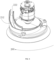
FIG. 1 is a schematic structural diagram of a sander provided by this application; -
FIG. 2 is a schematic diagram 1 of the exploded structure of a sander provided by this application; -
FIG. 3 is a schematic diagram 2 of the exploded structure of a sander provided by this application; -
FIG. 4 is a schematic diagram 3 of the exploded structure of a sander provided by this application; -
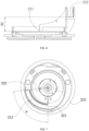
FIG. 5 is a partial structural schematic diagram of a sander provided by this application; -
FIG. 6 is a partial structural front view of a sander provided by this application; -
FIG. 7 is a partial structural top view of a sander provided by this application; -
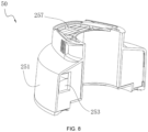
FIG. 8 is a schematic structural diagram of a dust collection device and filter provided by this application; -
FIG. 9 is a schematic diagram of the exploded structure of a dust collecting device and filter provided by this application; -
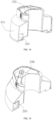
FIG. 10 is a schematic structural diagram of a dust collecting device provided by this application; -
FIG. 11 is a front view of a dust collecting device provided by this application; -
FIG. 12 is a schematic structural diagram of another dust collection device provided by this application; -
FIG. 13 is a front view of another dust collecting device provided by this application; -
FIG. 14 is a schematic structural diagram of yet another dust collection device provided by this application; -
FIG. 15 is a partial structural schematic diagram of yet another dust collection device provided by this application; -
FIG. 16 is a cross-sectional view of yet another dust collecting device provided by the present application; -
FIG. 17 is a partial structural schematic diagram 2 of yet another dust collection device provided by this application; -
FIG. 18 is a partial structural schematic diagram 3 of yet another dust collecting device provided by this application; -
FIG. 19 is a front view of another sander provided by this application; -
FIG. 20 is a side view of another sander provided by the present application; and -
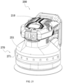
FIG. 21 is a schematic structural diagram of yet another sander provided by this application. - Before any examples of this application are explained in detail, it is to be understood that this application is not limited to its application to the structural details and the arrangement of components set forth in the following description or illustrated in the above drawings.
- In this application, the terms "comprising", "including", "having" or any other variation thereof are intended to cover an inclusive inclusion such that a process, method, article or device comprising a series of elements includes not only those series of elements, but also other elements not expressly listed, or elements inherent in the process, method, article, or device. Without further limitations, an element defined by the phrase "comprising a ..." does not preclude the presence of additional identical elements in the process, method, article, or device comprising that element.
- In this application, the term "and/or" is a kind of association relationship describing the relationship between associated objects, which means that there can be three kinds of relationships. For example, A and/or B can indicate that A exists alone, A and B exist simultaneously, and B exists alone. In addition, the character "/" in this application generally indicates that the contextual associated objects belong to an "and/or" relationship.
- In this application, the terms "connection", "combination", "coupling" and "installation" may be direct connection, combination, coupling or installation, and may also be indirect connection, combination, coupling or installation. Among them, for example, direct connection means that two members or assemblies are connected together without intermediaries, and indirect connection means that two members or assemblies are respectively connected with at least one intermediate members and the two members or assemblies are connected by the at least one intermediate members. In addition, "connection" and "coupling" are not limited to physical or mechanical connections or couplings, and may include electrical connections or couplings.
- In this application, it is to be understood by those skilled in the art that a relative term (such as "about", "approximately", and "substantially") used in conjunction with quantity or condition includes a stated value and has a meaning dictated by the context. For example, the relative term includes at least a degree of error associated with the measurement of a particular value, a tolerance caused by manufacturing, assembly, and use associated with the particular value, and the like. Such relative term should also be considered as disclosing the range defined by the absolute values of the two endpoints. The relative term may refer to plus or minus of a certain percentage (such as 1%, 5%, 10%, or more) of an indicated value. A value that did not use the relative term should also be disclosed as a particular value with a tolerance. In addition, "substantially" when expressing a relative angular position relationship (for example, substantially parallel, substantially perpendicular), may refer to adding or subtracting a certain degree (such as 1 degree, 5 degrees, 10 degrees or more) to the indicated angle.
- In this application, those skilled in the art will understand that a function performed by an assembly may be performed by one assembly, multiple assemblies, one member, or multiple members. Likewise, a function performed by a member may be performed by one member, an assembly, or a combination of members.
- In this application, the terms "up", "down", "left", "right", "front", and "rear" " and other directional words are described based on the orientation or positional relationship shown in the drawings, and should not be understood as limitations to the examples of this application. In addition, in this context, it also needs to be understood that when it is mentioned that an element is connected "above" or "under" another element, it can not only be directly connected "above" or "under" the other element, but can also be indirectly connected "above" or "under" the other element through an intermediate element. It should also be understood that orientation words such as upper side, lower side, left side, right side, front side, and rear side do not only represent perfect orientations, but can also be understood as lateral orientations. For example, lower side may include directly below, bottom left, bottom right, front bottom, and rear bottom.
- As shown in
FIGS. 1 to 7 , asander 200 includes ahousing 210, abase plate assembly 220, adrive assembly 230, amain switch assembly 240, adust collection device 251, and anenergy source 260. Theenergy source 260 is used for supplying energy to thesander 200. Theenergy source 260 may be alternating current power or direct current power such as the battery pack or another portable mobile power supply. Thedust collection device 251 may be a dust collection bag or a dust collection box; or thesander 200 may be connected to a vacuum cleaner, and the vacuum cleaner serves as thedust collection device 251. In this example, the case where thedust collection device 251 is the dust collection box is used as an example so that thedust collection device 251 is in the shape of a box, thereby further enhancing the integrity between thedust collection device 251 and thehousing 210. - The
dust collection device 251 may be detachably mounted onto thehousing 210 so that it is convenient to dump the dust in thedust collection device 251. Thedust collection device 251 has an assembly state in which thedust collection device 251 is assembled with thehousing 210 and a disassembly state in which thedust collection device 251 is separated from thehousing 210. When thedust collection device 251 is in the assembly state, thehousing 210 and thedust collection device 251 together form the outer shape of thesander 200 so that the integrity is strong, and it is convenient for usage, storage, and transportation. In order that thedust collection device 251 and thehousing 210 are integrated, thedust collection device 251 may be arc-shaped such that when thedust collection device 251 is in the assembly state, the top surface, the bottom surface, and the inner side surface of thedust collection device 251 basically fit thehousing 210. An approximately arc-shaped polyline shape formed by splicing multiple straight lines is also considered to be the same as the technical concept of the present application and is also covered by the scope of the present application. - The
housing 210 and/or thedust collection device 251 are formed with agrip 211 for the user to hold. Themain switch assembly 240 is disposed on the front side of thehousing 210 and thegrip 211 so that the user can relatively conveniently trigger themain switch assembly 240 when holding thegrip 211. An accommodation portion is formed on the rear side of thehousing 210 and used for mounting theenergy source 260 such as the battery pack. - The
base plate assembly 220 is disposed at the bottom of thehousing 210, and thedrive assembly 230 is disposed in thehousing 210. Thebase plate assembly 220 includes abase plate 223 connected to a work accessory; thedrive assembly 230 includes anelectric motor 231, and theelectric motor 231 is used for driving thebase plate 223 so that thebase plate 223 and the work accessory swing relative to thehousing 210. Thebase plate 223 includes an upper surface and a lower surface that are opposite. The lower surface is used for mounting the work accessory. The work accessory may be the functional element such as the sandpaper. When thebase plate 223 moves eccentrically, the surface of a workpiece to be sanded can be continuously rubbed with the sandpaper, thereby implementing the function of sanding and polishing the workpiece to be sanded. - The
sander 200 further includes adust channel 212. Thedust channel 212 is disposed in thehousing 210. Dust is collected from thebase plate 223, flows into thedust channel 212, and then flows into thedust collection device 251 through thedust channel 212. Specifically, thebase plate 223 is provided with a through hole penetrating the upper surface and the lower surface, and dust enters thedust channel 212 through the through hole. - The
electric motor 231 includes a motor shaft for outputting power, and the motor shaft rotates about a motor axis. In this example, the motor axis extends basically along the up and down direction. Thesander 200 further includes anairflow element 234 drivable by theelectric motor 231. Theairflow element 234 is drivable by theelectric motor 231 to rotate about the central axis. When rotating, theairflow element 234 can generate the airflow, and the airflow drives dust such that the dust is collected from thebase plate 223, flows into thedust channel 212, and then flows into thedust collection device 251 through thedust channel 212. - The
housing 210 is further provided with acontrol panel 232 and aspeed regulation assembly 233. Thecontrol panel 232 is electrically connected to theelectric motor 231. Thespeed regulation assembly 233 is electrically connected to thecontrol panel 232. Thespeed regulation assembly 233 can control the rotational speed of theelectric motor 231. Thespeed regulation assembly 233 can be controlled by a speed regulation button on thehousing 210. - The
dust channel 212 includes adust inlet 221 and adust outlet 222. Thedust channel 212 has an upper sidewall and a lower sidewall along the up and down direction, where the distance from the upper sidewall to the lower sidewall gradually increases along a preset direction ofrotation 205. It is to be understood that the sucked dust flows from thedust inlet 221 to thedust outlet 222. In the vertical direction, thedust outlet 222 is higher than thedust inlet 221; thebase plate 223 extends in a first plane, and the projection of thedust channel 212 on the first plane is basically arc-shaped so that the resistance to dust flow is reduced and smooth dust collection is achieved. In addition, since the resistance to dust collection is reduced, the energy consumption of the sander is reduced. It is to be noted that the arc shape involved in the present application may be an arc along the internal contour of the housing or may be a curve or another non-circular arc such as an involute. - In this example, when the
sander 200 is in the load-free state, the working duration of thesander 200 when the battery pack consumes 10 WH of energy is defined as the functional time T of thesander 200, and the product of the load-free rotational speed N of theelectric motor 231 and the functional time T of thesander 200 is greater than or equal to 63000 rpm·min and less than or equal to 120000 rpm·min. In an example, the product of the load-free rotational speed N of theelectric motor 231 and the functional time T of thesander 200 is greater than or equal to 70000 rpm·min and less than or equal to 115000 rpm·min. In other examples, the product of the load-free rotational speed N of theelectric motor 231 and the functional time T of thesander 200 is greater than or equal to 77000 rpm·min and less than or equal to 110000 rpm·min. In this example, the functional time T of thesander 200 is greater than or equal to 7 min and less than or equal to 11 min. - For the
dust channel 212, the smaller the height difference between thedust outlet 222 and thedust inlet 221, the smaller the resistance to air flow. However, thedust outlet 222 connects with thedust collection device 251; the higher thedust outlet 222 is, the less likely thedust collection device 251 is blocked by dust. The height difference H1 in the vertical direction between thedust outlet 222 and thedust inlet 221 is greater than or equal to 9 mm and less than or equal to 41 mm. In some examples, the height difference H1 in the vertical direction between thedust outlet 222 and thedust inlet 221 is greater than or equal to 15 mm and less than or equal to 30 mm. In some examples, the height difference H1 in the vertical direction between thedust outlet 222 and thedust inlet 221 is 27 mm. - The included angle formed between a line between the
dust inlet 221 and the center point of thebase plate 223 and a line between thedust outlet 222 and the center point of thebase plate 223 is a first angle β, and the first angle β is greater than or equal to 60 degrees and less than or equal to 120 degrees so that the resistance of the airflow in thedust channel 212 is reduced. In some examples, the first angle β is greater than or equal to 80 degrees and less than or equal to 100 degrees. In some examples, the first angle β is equal to 60 degrees, 70 degrees, 80 degrees, 90 degrees, 100 degrees, 110 degrees, or 120 degrees. In an example, thedust inlet 221 and thedust outlet 222 of thedust channel 212 are both located in thehousing 210. In an example, the projection of thedust outlet 222 of thedust channel 212 on the first plane does not extend beyond the boundary range of thebase plate 223. In an example, thebase plate 223 is basically rectangular, and the center point of thebase plate 223 is the center point of the rectangular surface. - In some examples, the
dust channel 212 extends in a spiral shape between thedust inlet 221 and thedust outlet 222 so that thedust channel 212 rises gently and the airflow resistance is reduced. In some examples, thedust channel 212 extends in a straight line between thedust inlet 221 and thedust outlet 222. - The projection of the
dust channel 212 on the first plane is a first projection, and the first projection is completely located within the boundary of thebase plate 223 so that the structure is compact and the center of gravity is stable. The projection of thedust collection device 251 on the first plane is a second projection, and the second projection is completely located within the boundary of thebase plate 223 so that the structure is compact and the center of gravity is stable. The first projection may overlap the second projection. The area of the second projection is greater than half of the area of thebase plate 223. - A first electrostatic conductive assembly is disposed on the
dust collection device 251 and used for conducting static electricity from the dust collection device. The first electrostatic conductive assembly may be a metal sheet such as a copper sheet. - The
sander 200 further includes a second electrostatic conductive assembly. The second electrostatic conductive assembly includes a first conductive member and a second conductive member. Two ends of the first conductive member are separately connected to thedust channel 212 and the stator core of theelectric motor 231. Two ends of the second conductive member are separately connected to the stator core and thehousing 210. Since the human hand holds thehousing 210, the static electricity on thedust channel 212 is conducted by the human hand through the second electrostatic conductive assembly. - As shown in
FIGS. 8 and9 , thedust collection device 251 has adust collection cavity 252, anair inlet 253, and anair outlet 254, where theair inlet 253 and theair outlet 254 connect with thedust collection cavity 252. Theair inlet 253 connects with thedust outlet 222 of thedust channel 212. Therefore, the dust can enter thedust collection device 251 from thedust channel 212, and theair outlet 254 connects with the outside; after the airflow carrying dust enters thedust collection device 251, the dust falls into thedust collection cavity 252 under the action of the gravity, and the airflow flows out from theair outlet 254. - The
air inlet 253 connects with thedust outlet 222 of thedust channel 212. The area of theair inlet 253 is less than or equal to 400 mm2, ensuring sufficient intake air volume under the premise of fully utilizing the space. In some examples, the area of theair inlet 253 is less than or equal to 350 mm2. In some examples, the area of theair inlet 253 is less than or equal to 300 mm2. In some examples, the area of theair inlet 253 is equal to 250 mm2, 260 mm2, or 270 mm2. - A
filter 257 is disposed at theair outlet 254 of thedust collection device 251. If a small amount of dust flows out of theair outlet 254 with the airflow, thefilter 257 can filter the dust to prevent the dust from overflowing. Thefilter 257 includes aholder 258 andfilter paper 259. Thefilter paper 259 is mounted on theholder 258. Theholder 258 is detachably connected to theair outlet 254. Thefilter paper 259 is supported by theholder 258. Theholder 258 is easy to mount and disassemble. When thefilter paper 259 is replaced, theholder 258 may be disassembled. After thefilter paper 259 is replaced, theholder 258 is mounted again. Theholder 258 may engage with thedust collection device 251 in a snap-fit manner. - As shown in
FIG. 10 , oneair outlet 254 is provided and located at the top of thedust collection device 251. As shown inFIG. 11 , in the vertical direction, the bottom edge of theair inlet 253 is higher than the bottom surface of thedust collection cavity 252, and the height difference H2 between the bottom edge of theair inlet 253 and the bottom surface of thedust collection cavity 252 is greater than or equal to 5 mm and less than or equal to 20 mm so that the dust in thedust collection cavity 252 is prevented from overflowing from theair inlet 253, theair inlet 253 is prevented from being blocked, thedust collection cavity 252 has a certain space, and the dust collection amount is improved. - As shown in
FIGS. 12 and 13 , at least twoair outlets 254 are provided so that air permeability and exhaust air volume are increased, and the dust collection is smoother. Theair outlets 254 may be disposed on the top or side surface of thedust collection device 251. Specifically, theair outlet 254 is located on a side of thedust collection device 251 facing thehousing 210, that is, theair outlet 254 is disposed on the inner side surface of thedust collection device 251 so that the outer surface of thedust collection device 251 is flat. - Each
air outlet 254 is provided with thefilter 257, and thefilter 257 can filter the dust and prevent the dust from overflowing. - In a layout where the
air outlet 254 is located on the side of thedust collection device 251 facing thehousing 210, to facilitate air output, a gap is formed between thedust collection device 251 and thehousing 210, and the gap connects theair outlet 254 with the outside. As shown inFIG. 15 , thehousing 210 includes afirst adapting surface 215, and the inner side surface of thedust collection device 251 is asecond adapting surface 216. When thedust collection device 251 is assembled with thehousing 210, a gap is formed between thefirst adapting surface 215 and thesecond adapting surface 216, thereby facilitating air output at theair outlet 254. The gap has a dimension of 1 mm to 3 mm, preferably, 2 mm. - As shown in
FIG. 2 , thehousing 210 includes a mountingplate 213. The mountingplate 213 has a first mountingsurface 231. Thedust collection device 251 is detachably connected to the first mountingsurface 231. Thefirst mounting surface 231 is a mirror-finished surface so that the friction during assembly is reduced, thereby facilitating the disassembly and assembly of thedust collection device 251. - The
dust collection device 251 may engage with thehousing 210 in a snap-fit manner, specifically, through aball snap catch 214. Theball snap catch 214 is disposed on the first mountingsurface 231. During installation, thedust collection device 251 is pushed to thehousing 210 so that thedust collection device 251 slides along the first mountingsurface 231 to engage with theball snap catch 214 in a snap-fit manner. Since the first mountingsurface 231 is the mirror-finished surface, the friction during assembly is reduced. - The mounting
plate 213 further includes asecond mounting surface 232. Thesecond mounting surface 232 is located on the outer circumference of the first mountingsurface 231 and is lower than the first mountingsurface 231. Thesecond mounting surface 232 has a rougher surface than the first mountingsurface 231. Thedust collection device 251 abuts against the second mountingsurface 232 so that the contact area and friction between thedust collection device 251 and thehousing 210 are increased, and the connection is stable. - As shown in
FIGS. 14 to 18 , in an example, thedust collection device 251 has thedust collection cavity 252, a cyclonedust collection assembly 256 is disposed in thedust collection cavity 252, the cyclonedust collection assembly 256 has theair inlet 253, adust exhaust outlet 250, and theair outlet 254, theair inlet 253 connects with thedust outlet 222, thedust exhaust outlet 250 connects with thedust collection cavity 252, and theair outlet 254 connects with the outside. Due to the arrangement of the cyclonedust collection assembly 256, theair inlet 253 does not need to be higher than the bottom surface of thedust collection cavity 252, and the dust in thedust collection cavity 252 does not overflow from theair inlet 253. - The working principle of the cyclone
dust collection assembly 256 is conventional technology, and the details are not repeated here. The airflow carrying dust rises after entering from theair inlet 253. Under the action of the cyclonedust collection assembly 256, the dust falls from thedust exhaust outlet 250, and the airflow is discharged from theair outlet 254. Theair outlet 254 may be disposed on the outer sidewall of thedust collection device 251, so the top of thedust collection device 251 does not need to be opened and can be sealed. - As shown in
FIGS. 19 and20 , thesander 200 further includes anillumination device 270. Thehousing 210 includes ahousing top 202, ahousing bottom 203, and acontraction portion 204 disposed between thehousing top 202 and thehousing bottom 203. Thecontraction portion 204 is a section of thehousing 210 that contracts inward. In the field of sanders, thecontraction portion 204 is often used for users to hold, thereby forming a holding area that is different from thehousing top 202 of thehousing 210. Atransition portion 205 is formed in the process of thecontraction portion 204 extending upward to thehousing top 202 of the housing. When the user holds thecontraction portion 204, thetransition portion 205 can be held up by the tiger's mouth of a hand and the fingers can be placed on thehousing top 202. - Nowadays, with the
sander 200 being more compact, the height of thesander 200 is getting lower and lower. The demand that thecontraction portion 204 and thetransition portion 205 to be held is reduced, so that the user can obtain the correct holding position when holding the hand on thehousing top 202 of thehousing 210, thereby holding thesander 200 firmly. At the same time, the lighting demand of thesander 200 is gradually reflected. Thesander 200 of the present application is provided with an illumination device 70 to meet the use demand when the light is insufficient. - The
illumination device 270 includes a light-emittingportion 271. The light-emittingportion 271 is disposed on thehousing 210 and located above thecontraction portion 204. Thebase plate 223 is within the illumination range of the light-emittingportion 271. The position of the light-emittingportion 271 is such that thebase plate 223 is within the illumination range of the light-emittingportion 271. Since a sanding member on thebase plate 223 sands a member to be sanded, during work, the work region is within the illumination range of the light-emittingportion 271, which is convenient for an operator to observe, thereby improving the user experience. - In some examples, the light-emitting
portion 271 is disposed at the junction of thecontraction portion 204 and thehousing top 202. In this embodiment, the illumination device 70 is below themain switch assembly 240 and is above thecontraction portion 204. It is to be understood that the light-emittingportion 271 emits light downward or obliquely downward to illuminate the region where thebase plate 223 is located. - The
illumination device 270 is detachably disposed relative to thehousing 210, thereby facilitating maintenance. The light-emittingportion 271 and thehousing 210 may be connected in a screw connection manner, a snap-fit manner, or a magnetic attraction connection manner. - In one embodiment, the overall height of the
sander 200 is less than or equal to 130 mm. In one embodiment, the overall height of thesander 200 is less than or equal to 120 mm. In one embodiment, the overall height of thesander 200 is less than or equal to 110 mm. In one embodiment, the overall height of thesander 200 is less than or equal to 100 mm. In some embodiments, the overall height of thesander 200 may be 98 mm, 103 mm, 105 mm, 108 mm or 112 mm, etc. The overall height of thesander 200 refers to the distance from the top of thehousing top 202 to the bottom of thebase plate 223, excluding the distance of the battery pack protruding from thehousing top 202. With such a configuration, for the sander with a short overall height, theillumination device 270 disposed in thetransition portion 205 will be of space advantage. - In some examples, the battery pack of the
sander 200 supplies electrical energy to theillumination device 270. In some examples, thesander 200 further includes an illumination power supply that supplies power to theillumination device 270, and the illumination power supply is a power supply component independent of the battery pack. Optionally, the illumination power supply may be a battery, a storage battery, or the like that is detachably connected to thesander 200. In some examples, thesander 200 further includes a self-powered module. The self-powered module is a component that can generate power through sunlight. The module that generates power through sunlight is an existing component, so the working principle and detailed structure are not described in detail. - The light-emitting
portion 271 is one or a combination of at least two of a point light source, an area light source, and a light-emitting diode (LED) light source. The light-emittingportion 271 may be annular or rectangular, so as to increase the luminous area. - One light-emitting
portion 271 may be provided, or multiple light-emittingportions 271 may be provided. When multiple light-emittingportions 271 are provided, the light-emittingportions 271 may be located at different positions, and the light-emittingportions 271 may be turned on or off simultaneously or independently. In some examples, theillumination device 270 includes at least two light-emittingportions 271. The at least two light-emittingportions 271 may be turned on separately. Optionally, one of the light-emittingportions 271 may be set to a low-beam mode, and one of the light-emittingportions 271 may be set to a high-beam mode, so as to satisfy different usage requirements. Of course, the two light-emittingportions 271 may be turned on simultaneously so that theillumination device 270 has a higher illumination intensity and a larger illumination range. It is to be noted that the low-beam mode and the high-beam mode are collectively referred to as light emission modes of the light-emittingportion 271. Optionally, different light-emittingportions 271 may be disposed at different positions of thesander 200 so that while illuminating thebase plate 223 of thesander 200, theillumination device 270 can illuminate the front, sides, and rear of thesander 200, thereby preventing the user from bumping due to unclear visibility of the surrounding environment. - The
illumination device 270 can be turned on when theelectric motor 231 is turned on, and theillumination device 270 can be turned off in a preset time after theelectric motor 231 stops rotating. The on and off of theillumination device 270 and theelectric motor 231 are linked so that theillumination device 270 can be turned on and off intelligently, thereby improving the user experience. Optionally, the preset time may be 3s, 5s, 7s, or the like and is not specifically limited here. In some examples, the user may configure theillumination device 270 to select the appropriate preset time. - The light-emitting
portion 271 can emit light of at least two colors. Optionally, the light-emittingportion 271 can emit white light, which has better brightness and is suitable for use in normal weather. The light-emittingportion 271 can emit yellow light, which has strong penetrability and is more suitable for use in foggy days. Optionally, the light-emittingportion 271 can emit red light. During working in complex construction conditions, turning on the red light can serve as a warning to the outside. In other examples, the colors emitted by the light-emittingportion 271 are not limited to the preceding colors. Optionally, theillumination device 270 may include at least two light-emittingportions 271, and each light-emittingportion 271 correspondingly emits light of one color. - In some examples, the
illumination device 270 is configured to be capable of adjusting the light colors of the light-emittingportions 271 according to ambient brightness. Theillumination device 270 may be provided with a light sensor. When the light sensor recognizes that the ambient brightness decreases to a first threshold, the light-emittingportion 271 switches from a first color to a second color. - The
illumination device 270 is configured to be capable of adjusting the brightness of the light-emittingportions 271 according to the ambient brightness. In some examples, theillumination device 270 may be provided with the light sensor. When the light sensor recognizes that the ambient brightness decreases to the first threshold, the light-emittingportions 271 automatically light up. In some examples, when the light sensor recognizes that the ambient brightness increases to a second threshold, the brightness of the light-emittingportions 271 is automatically adjusted to darker. - In some examples, the light-emitting
portions 271 have at least two brightnesses. When the user presses the button for the first time, the light-emittingportions 271 emit light of the first brightness. When the user presses the button for the second time, the light-emittingportions 271 emit light of the second brightness. When the user presses the button for the third time, the light-emittingportions 271 are turned off. - The
illumination device 270 can perform at least one of a safety indication, a fault indication, a battery pack power reminder, or a projected image. Optionally, the light-emittingportions 271 can flash at different frequencies and indicate the safety indication, the fault indication, and the power reminder at different strobe frequencies. It is to be understood that the light-emittingportions 271 can emit light of different colors to separately indicate the safety indication, the fault indication, and the power reminder. Optionally, the light-emittingportions 271 can project an image, and the image may be a brand logo or a model of the product, thereby achieving a certain publicity effect. - The
illumination device 270 further includes a switch assembly, where the switch assembly can turn on and off the light-emittingportions 271, and/or adjust the brightness of the light-emittingportions 271, and/or select emitted colors of the light-emittingportions 271, and/or trigger the light-emittingportions 271 to project an image, and/or select the light emission modes of the light-emittingportions 271. In an example, the maximum distance between the switch assembly and the light-emittingportion 271 is less than or equal to 5 cm so that the length of the cable between the switch assembly and the light-emittingportion 271 can be shortened, and the cables inside thesander 200 are neat and are not easily damaged. The switch assembly may be located above thegrip 211 for easy operation. - In some examples, the
illumination device 270 is configured to be capable of transmitting control signals to and from a user terminal to adjust luminescence parameters of the light-emittingportions 271. Specifically, theillumination device 270 further includes a communication module. The user may communicate with the communication module through a terminal device such as a mobile phone to control the light-emittingportions 271. Optionally, the communication module may be a Bluetooth module, a Wi-Fi module, or the like. The luminescence parameters include, but are not limited to, turning on and off the light-emittingportions 271, adjusting the brightness of the light-emittingportions 271, selecting the emitted colors of the light-emittingportions 271, triggering the light-emittingportions 271 to project an image, selecting the light emission modes of the light-emittingportions 271, and adjusting the strobe frequencies of the light-emittingportions 271. The user terminal may be a portable terminal such as a tablet or a mobile phone, so as to adjust the luminescence parameters of the light-emittingportions 271 easily. - In the scheme of the
illumination device 270 disclosed inFigures 19 and20 , the light-emittingportion 271 can protrude from an outer surface of thehousing 210, or can be embedded in the interior of thehousing 210 so as to be substantially flush with the outer surface of thehousing 210, or can be slightly lower than the outer surface of thehousing 210. - As shown in
FIG. 21 , in the case where thesander 200 includes thedust collection device 251, theillumination device 270 includes the light-emittingportions 271, and the light-emittingportions 271 are disposed on thedust collection device 251, so as to make full use of the space of thedust collection device 251. Since the outer circumferential surface of thedust collection device 251 has a larger dimension, the light-emittingportions 271 disposed on thedust collection device 251 are less likely to be blocked. For the specific structure of thedust collection device 251, reference may be made to the relevant content of the precedingdust collection device 251. For the specific structures of the light-emittingportions 271, reference may be made to the relevant content of the preceding light-emittingportions 271. - In some examples, the light-emitting
portions 271 are arranged around the circumferential direction of thedust collection device 251 so that the light has a larger coverage area, the illumination range is increased, and the light uniformity is ensured. - In some examples, the light-emitting
portions 271 are disposed inside and/or outside thedust collection device 251. The light-emittingportions 271 may be disposed on the outer circumferential surface of thedust collection device 251, on the inner circumferential surface of thedust collection device 251, or on both the outer circumferential surface and the inner circumferential surface of thedust collection device 251. - In some examples, some light-emitting
portions 271 are disposed on thedust collection device 251, and some light-emittingportions 271 are disposed on thehousing 210. - In some examples, the
dust collection device 251 is detachably connected to thehousing 210, and thedust collection device 251 has the assembly state in which thedust collection device 251 is assembled with thehousing 210. When thedust collection device 251 is in the assembly state, theillumination device 270 is turned on. The state of thedust collection device 251 is linked to the on and off of theillumination device 270 so that theillumination device 270 can be turned on intelligently, thereby improving the user experience. Thedust collection device 251 has the disassembly state in which thedust collection device 251 is separated from thehousing 210. In some examples, when thedust collection device 251 is in the disassembly state, theillumination device 270 is turned off. - In some embodiments, the
contraction portion 204 and thedust collecting device 251 may be separately provided withdifferent illumination devices 270, or differentlight emitting portions 271. - The above illustrates and describes the basic principles, main features, and advantages of the present invention. It is to be understood by those skilled in the art that the preceding examples do not limit the present invention in any form, and technical solutions obtained by means of equivalent substitution or equivalent transformation fall within the scope of the present invention.
Claims (15)
- A sander, comprising:A housing, the housing comprising a housing top, a housing bottom and a contraction portion arranged between the housing top and the housing bottom;A base plate assembly, comprising a base plate;A driving assembly, comprising a motor, the motor being used to drive the base plate;An illumination device, comprising a light-emitting portion;Characterized in that the light-emitting portion is arranged in the housing and located above the contraction portion, and the base plate is within an illumination range of the light-emitting portion.
- The sander according to claim 1, characterized in that the light-emitting portion is arranged at the junction of the contraction portion and the housing top.
- The sander according to claim 1, characterized in that the illumination device is detachably arranged relative to the housing.
- The sander according to claim 1, characterized in that the light-emitting portion is one of or at least two of a point light source, an area light source, and an LED light source.
- The sander according to claim 1, characterized in that the illumination device can be turned on when the electric motor is turned on, and the illumination device can be turned off in a preset time when the motor stops rotating.
- The sander according to claim 1, characterized in that the light-emitting part can emit light of at least two colors.
- The sander according to claim 1, characterized in that the illumination device is configured to adjust the brightness of the light-emitting portion according to ambient brightness.
- The sander according to claim 1, characterized in that the illumination device can provide at least one of safety indication, fault indication, battery pack power reminder or projected image.
- The sander according to claim 1, characterized in that the illumination device also includes a switch component, and the switch component can: open and close the light-emitting portion, and/or adjust the brightness of the light-emitting portion, and/or select the light color of the light-emitting portion, and/or trigger the light-emitting portion to project, and/or select the light mode of the light-emitting portion.
- The sander according to claim 1, characterized in that the illumination device is configured to transmit a control signal to a user terminal to adjust the light-emitting parameters of the light-emitting portion.
- The sander according to claim 1, characterized in that an overall height of the sander is less than or equal to 120 mm.
- The sander according to claim 1, characterized in that an overall height of the sander is less than or equal to 110 mm.
- The sander according to claim 1, characterized in that an overall height of the sander is less than or equal to 100 mm.
- The sander according to claim 1, characterized in that further comprising a dust channel, which is arranged in the housing, and the dust channel includes a dust inlet and a dust outlet, dust is collected from the base plate and flows into the dust channel through the dust inlet, and then flows into the dust collecting device through the dust outlet, the dust collecting device is provided with the light-emitting portion, and the dust collecting device and the contraction portion are provided with different light-emitting portions.
- The sander according to claim 14, characterized in that the dust collecting device can be detachably mounted to the housing.
Applications Claiming Priority (1)
| Application Number | Priority Date | Filing Date | Title |
|---|---|---|---|
| CN202311247654 | 2023-09-25 |
Publications (2)
| Publication Number | Publication Date |
|---|---|
| EP4527551A1 true EP4527551A1 (en) | 2025-03-26 |
| EP4527551B1 EP4527551B1 (en) | 2025-12-03 |
Family
ID=92633727
Family Applications (1)
| Application Number | Title | Priority Date | Filing Date |
|---|---|---|---|
| EP24197785.9A Active EP4527551B1 (en) | 2023-09-25 | 2024-09-02 | Sander |
Country Status (2)
| Country | Link |
|---|---|
| EP (1) | EP4527551B1 (en) |
| CN (2) | CN223029436U (en) |
Citations (4)
| Publication number | Priority date | Publication date | Assignee | Title |
|---|---|---|---|---|
| US20080311831A1 (en) * | 2007-06-13 | 2008-12-18 | Milbourne Rodney D | Sander |
| US7914167B2 (en) * | 2008-08-01 | 2011-03-29 | 3M Innovative Properties Company | Surface modifying apparatus having illumination system and method thereof |
| US20180170321A1 (en) * | 2016-12-21 | 2018-06-21 | Ronald Lipson | Intelligent polisher/buffer with selective color-matching light |
| CN214393689U (en) * | 2020-12-24 | 2021-10-15 | 常州合力电器有限公司 | Sanding machine |
-
2024
- 2024-08-30 CN CN202422124552.5U patent/CN223029436U/en active Active
- 2024-08-30 CN CN202422133193.XU patent/CN223029404U/en active Active
- 2024-09-02 EP EP24197785.9A patent/EP4527551B1/en active Active
Patent Citations (4)
| Publication number | Priority date | Publication date | Assignee | Title |
|---|---|---|---|---|
| US20080311831A1 (en) * | 2007-06-13 | 2008-12-18 | Milbourne Rodney D | Sander |
| US7914167B2 (en) * | 2008-08-01 | 2011-03-29 | 3M Innovative Properties Company | Surface modifying apparatus having illumination system and method thereof |
| US20180170321A1 (en) * | 2016-12-21 | 2018-06-21 | Ronald Lipson | Intelligent polisher/buffer with selective color-matching light |
| CN214393689U (en) * | 2020-12-24 | 2021-10-15 | 常州合力电器有限公司 | Sanding machine |
Also Published As
| Publication number | Publication date |
|---|---|
| EP4527551B1 (en) | 2025-12-03 |
| CN223029436U (en) | 2025-06-27 |
| CN223029404U (en) | 2025-06-27 |
Similar Documents
| Publication | Publication Date | Title |
|---|---|---|
| US11555583B2 (en) | Multifunction flexible LED flashlight | |
| US10821595B2 (en) | Power tool | |
| US6918331B2 (en) | Lighted cutting tools | |
| US5954458A (en) | Cordless drill with adjustable light | |
| US20240172588A1 (en) | Riding lawn mower | |
| CN102345800B (en) | There is the lamp of orientable lighting source | |
| EP2002930B1 (en) | Sander | |
| JP2017531567A (en) | Grinding machine having at least one first housing part and lighting device module | |
| CN115570540A (en) | Power tool | |
| US20240198483A1 (en) | Sander | |
| EP4527551B1 (en) | Sander | |
| CN207290007U (en) | Power tool | |
| CN211335405U (en) | Take wireless control's wheel hub dress trim cover | |
| CN207893464U (en) | A kind of novel and multifunctional utility light | |
| CN210790435U (en) | Eccentric polishing machine for automobile | |
| EP4663067A1 (en) | Hair dryer and handheld hair dryer | |
| KR200432784Y1 (en) | Portable xenon searchlight with LED lamp | |
| TWM258818U (en) | Saw blade hood with lighting device | |
| US20260132919A1 (en) | Lighting Element for a Power Tool | |
| CN210398574U (en) | Effectual light of blowing of air supply | |
| CN210351576U (en) | Bluetooth headset with waterproof construction | |
| CN223262840U (en) | Portable dust removing equipment | |
| CN218209063U (en) | LED lamp with adjustable luminance | |
| CN223938295U (en) | Waist-hanging fan | |
| CN212064099U (en) | Light supplement lamp |
Legal Events
| Date | Code | Title | Description |
|---|---|---|---|
| PUAI | Public reference made under article 153(3) epc to a published international application that has entered the european phase |
Free format text: ORIGINAL CODE: 0009012 |
|
| STAA | Information on the status of an ep patent application or granted ep patent |
Free format text: STATUS: THE APPLICATION HAS BEEN PUBLISHED |
|
| AK | Designated contracting states |
Kind code of ref document: A1 Designated state(s): AL AT BE BG CH CY CZ DE DK EE ES FI FR GB GR HR HU IE IS IT LI LT LU LV MC ME MK MT NL NO PL PT RO RS SE SI SK SM TR |
|
| STAA | Information on the status of an ep patent application or granted ep patent |
Free format text: STATUS: REQUEST FOR EXAMINATION WAS MADE |
|
| 17P | Request for examination filed |
Effective date: 20250814 |
|
| GRAP | Despatch of communication of intention to grant a patent |
Free format text: ORIGINAL CODE: EPIDOSNIGR1 |
|
| STAA | Information on the status of an ep patent application or granted ep patent |
Free format text: STATUS: GRANT OF PATENT IS INTENDED |
|
| GRAS | Grant fee paid |
Free format text: ORIGINAL CODE: EPIDOSNIGR3 |
|
| RIC1 | Information provided on ipc code assigned before grant |
Ipc: B24B 23/00 20060101AFI20250922BHEP Ipc: B25F 5/02 20060101ALI20250922BHEP Ipc: F21V 33/00 20060101ALN20250922BHEP |
|
| GRAA | (expected) grant |
Free format text: ORIGINAL CODE: 0009210 |
|
| STAA | Information on the status of an ep patent application or granted ep patent |
Free format text: STATUS: THE PATENT HAS BEEN GRANTED |
|
| INTG | Intention to grant announced |
Effective date: 20251013 |
|
| AK | Designated contracting states |
Kind code of ref document: B1 Designated state(s): AL AT BE BG CH CY CZ DE DK EE ES FI FR GB GR HR HU IE IS IT LI LT LU LV MC ME MK MT NL NO PL PT RO RS SE SI SK SM TR |
|
| REG | Reference to a national code |
Ref country code: CH Ref legal event code: F10 Free format text: ST27 STATUS EVENT CODE: U-0-0-F10-F00 (AS PROVIDED BY THE NATIONAL OFFICE) Effective date: 20251203 Ref country code: GB Ref legal event code: FG4D |
|
| REG | Reference to a national code |
Ref country code: DE Ref legal event code: R096 Ref document number: 602024001520 Country of ref document: DE |
|
| REG | Reference to a national code |
Ref country code: IE Ref legal event code: FG4D |
|
| REG | Reference to a national code |
Ref country code: NL Ref legal event code: MP Effective date: 20251203 |
|
| PG25 | Lapsed in a contracting state [announced via postgrant information from national office to epo] |
Ref country code: ES Free format text: LAPSE BECAUSE OF FAILURE TO SUBMIT A TRANSLATION OF THE DESCRIPTION OR TO PAY THE FEE WITHIN THE PRESCRIBED TIME-LIMIT Effective date: 20251203 |
|
| REG | Reference to a national code |
Ref country code: LT Ref legal event code: MG9D |
|
| PG25 | Lapsed in a contracting state [announced via postgrant information from national office to epo] |
Ref country code: NO Free format text: LAPSE BECAUSE OF FAILURE TO SUBMIT A TRANSLATION OF THE DESCRIPTION OR TO PAY THE FEE WITHIN THE PRESCRIBED TIME-LIMIT Effective date: 20260303 |
|
| PG25 | Lapsed in a contracting state [announced via postgrant information from national office to epo] |
Ref country code: FI Free format text: LAPSE BECAUSE OF FAILURE TO SUBMIT A TRANSLATION OF THE DESCRIPTION OR TO PAY THE FEE WITHIN THE PRESCRIBED TIME-LIMIT Effective date: 20251203 Ref country code: HR Free format text: LAPSE BECAUSE OF FAILURE TO SUBMIT A TRANSLATION OF THE DESCRIPTION OR TO PAY THE FEE WITHIN THE PRESCRIBED TIME-LIMIT Effective date: 20251203 |
|
| PG25 | Lapsed in a contracting state [announced via postgrant information from national office to epo] |
Ref country code: RS Free format text: LAPSE BECAUSE OF FAILURE TO SUBMIT A TRANSLATION OF THE DESCRIPTION OR TO PAY THE FEE WITHIN THE PRESCRIBED TIME-LIMIT Effective date: 20260303 |
|
| PG25 | Lapsed in a contracting state [announced via postgrant information from national office to epo] |
Ref country code: PL Free format text: LAPSE BECAUSE OF FAILURE TO SUBMIT A TRANSLATION OF THE DESCRIPTION OR TO PAY THE FEE WITHIN THE PRESCRIBED TIME-LIMIT Effective date: 20251203 |
|
| PG25 | Lapsed in a contracting state [announced via postgrant information from national office to epo] |
Ref country code: LV Free format text: LAPSE BECAUSE OF FAILURE TO SUBMIT A TRANSLATION OF THE DESCRIPTION OR TO PAY THE FEE WITHIN THE PRESCRIBED TIME-LIMIT Effective date: 20251203 |
|
| PG25 | Lapsed in a contracting state [announced via postgrant information from national office to epo] |
Ref country code: BG Free format text: LAPSE BECAUSE OF FAILURE TO SUBMIT A TRANSLATION OF THE DESCRIPTION OR TO PAY THE FEE WITHIN THE PRESCRIBED TIME-LIMIT Effective date: 20251203 |
|
| REG | Reference to a national code |
Ref country code: AT Ref legal event code: MK05 Ref document number: 1863144 Country of ref document: AT Kind code of ref document: T Effective date: 20251203 |
|
| PG25 | Lapsed in a contracting state [announced via postgrant information from national office to epo] |
Ref country code: NL Free format text: LAPSE BECAUSE OF FAILURE TO SUBMIT A TRANSLATION OF THE DESCRIPTION OR TO PAY THE FEE WITHIN THE PRESCRIBED TIME-LIMIT Effective date: 20251203 |
|
| PG25 | Lapsed in a contracting state [announced via postgrant information from national office to epo] |
Ref country code: LT Free format text: LAPSE BECAUSE OF FAILURE TO SUBMIT A TRANSLATION OF THE DESCRIPTION OR TO PAY THE FEE WITHIN THE PRESCRIBED TIME-LIMIT Effective date: 20251203 |
|
| PG25 | Lapsed in a contracting state [announced via postgrant information from national office to epo] |
Ref country code: SM Free format text: LAPSE BECAUSE OF FAILURE TO SUBMIT A TRANSLATION OF THE DESCRIPTION OR TO PAY THE FEE WITHIN THE PRESCRIBED TIME-LIMIT Effective date: 20251203 |
|
| PG25 | Lapsed in a contracting state [announced via postgrant information from national office to epo] |
Ref country code: IT Free format text: LAPSE BECAUSE OF FAILURE TO SUBMIT A TRANSLATION OF THE DESCRIPTION OR TO PAY THE FEE WITHIN THE PRESCRIBED TIME-LIMIT Effective date: 20251203 |
|
| PG25 | Lapsed in a contracting state [announced via postgrant information from national office to epo] |
Ref country code: AT Free format text: LAPSE BECAUSE OF FAILURE TO SUBMIT A TRANSLATION OF THE DESCRIPTION OR TO PAY THE FEE WITHIN THE PRESCRIBED TIME-LIMIT Effective date: 20251203 |
|
| PG25 | Lapsed in a contracting state [announced via postgrant information from national office to epo] |
Ref country code: EE Free format text: LAPSE BECAUSE OF FAILURE TO SUBMIT A TRANSLATION OF THE DESCRIPTION OR TO PAY THE FEE WITHIN THE PRESCRIBED TIME-LIMIT Effective date: 20251203 |
|
| PG25 | Lapsed in a contracting state [announced via postgrant information from national office to epo] |
Ref country code: PT Free format text: LAPSE BECAUSE OF FAILURE TO SUBMIT A TRANSLATION OF THE DESCRIPTION OR TO PAY THE FEE WITHIN THE PRESCRIBED TIME-LIMIT Effective date: 20260406 Ref country code: IS Free format text: LAPSE BECAUSE OF FAILURE TO SUBMIT A TRANSLATION OF THE DESCRIPTION OR TO PAY THE FEE WITHIN THE PRESCRIBED TIME-LIMIT Effective date: 20260403 |
|
| PG25 | Lapsed in a contracting state [announced via postgrant information from national office to epo] |
Ref country code: CZ Free format text: LAPSE BECAUSE OF FAILURE TO SUBMIT A TRANSLATION OF THE DESCRIPTION OR TO PAY THE FEE WITHIN THE PRESCRIBED TIME-LIMIT Effective date: 20251203 |
|
| PG25 | Lapsed in a contracting state [announced via postgrant information from national office to epo] |
Ref country code: SK Free format text: LAPSE BECAUSE OF FAILURE TO SUBMIT A TRANSLATION OF THE DESCRIPTION OR TO PAY THE FEE WITHIN THE PRESCRIBED TIME-LIMIT Effective date: 20251203 |
|
| PG25 | Lapsed in a contracting state [announced via postgrant information from national office to epo] |
Ref country code: SE Free format text: LAPSE BECAUSE OF FAILURE TO SUBMIT A TRANSLATION OF THE DESCRIPTION OR TO PAY THE FEE WITHIN THE PRESCRIBED TIME-LIMIT Effective date: 20251203 |