EP4527535A1 - Systems and methods to monitor a welding arc - Google Patents
Systems and methods to monitor a welding arc Download PDFInfo
- Publication number
- EP4527535A1 EP4527535A1 EP24201205.2A EP24201205A EP4527535A1 EP 4527535 A1 EP4527535 A1 EP 4527535A1 EP 24201205 A EP24201205 A EP 24201205A EP 4527535 A1 EP4527535 A1 EP 4527535A1
- Authority
- EP
- European Patent Office
- Prior art keywords
- welding
- control
- impedance
- power supply
- current
- Prior art date
- Legal status (The legal status is an assumption and is not a legal conclusion. Google has not performed a legal analysis and makes no representation as to the accuracy of the status listed.)
- Pending
Links
Images



Classifications
-
- B—PERFORMING OPERATIONS; TRANSPORTING
- B23—MACHINE TOOLS; METAL-WORKING NOT OTHERWISE PROVIDED FOR
- B23K—SOLDERING OR UNSOLDERING; WELDING; CLADDING OR PLATING BY SOLDERING OR WELDING; CUTTING BY APPLYING HEAT LOCALLY, e.g. FLAME CUTTING; WORKING BY LASER BEAM
- B23K9/00—Arc welding or cutting
- B23K9/095—Monitoring or automatic control of welding parameters
- B23K9/0953—Monitoring or automatic control of welding parameters using computing means
-
- B—PERFORMING OPERATIONS; TRANSPORTING
- B23—MACHINE TOOLS; METAL-WORKING NOT OTHERWISE PROVIDED FOR
- B23K—SOLDERING OR UNSOLDERING; WELDING; CLADDING OR PLATING BY SOLDERING OR WELDING; CUTTING BY APPLYING HEAT LOCALLY, e.g. FLAME CUTTING; WORKING BY LASER BEAM
- B23K9/00—Arc welding or cutting
- B23K9/06—Arrangements or circuits for starting the arc, e.g. by generating ignition voltage, or for stabilising the arc
- B23K9/073—Stabilising the arc
- B23K9/0734—Stabilising of the arc power
-
- B—PERFORMING OPERATIONS; TRANSPORTING
- B23—MACHINE TOOLS; METAL-WORKING NOT OTHERWISE PROVIDED FOR
- B23K—SOLDERING OR UNSOLDERING; WELDING; CLADDING OR PLATING BY SOLDERING OR WELDING; CUTTING BY APPLYING HEAT LOCALLY, e.g. FLAME CUTTING; WORKING BY LASER BEAM
- B23K9/00—Arc welding or cutting
- B23K9/10—Other electric circuits therefor; Protective circuits; Remote controls
- B23K9/1006—Power supply
-
- B—PERFORMING OPERATIONS; TRANSPORTING
- B23—MACHINE TOOLS; METAL-WORKING NOT OTHERWISE PROVIDED FOR
- B23K—SOLDERING OR UNSOLDERING; WELDING; CLADDING OR PLATING BY SOLDERING OR WELDING; CUTTING BY APPLYING HEAT LOCALLY, e.g. FLAME CUTTING; WORKING BY LASER BEAM
- B23K9/00—Arc welding or cutting
- B23K9/10—Other electric circuits therefor; Protective circuits; Remote controls
- B23K9/1006—Power supply
- B23K9/1043—Power supply characterised by the electric circuit
- B23K9/1056—Power supply characterised by the electric circuit by using digital means
- B23K9/1062—Power supply characterised by the electric circuit by using digital means with computing means
Definitions
- This disclosure relates generally to welding systems and, more particularly, to systems and methods to monitor a welding arc.
- GMAW short circuit gas metal arc welding
- MIG metal inert gas
- GMAW GMAW
- MIG metal inert gas
- waveforms are used to control the current and/or voltage to provide an improved welding result.
- Some such waveforms include rapid changes in voltage and/or current, and between arc states such as a short circuit and an arc state.
- Some welding control schemes benefit from predicting the state of the welding arc and/or other aspects of the weld. For example, predicting the moment of reignition of the welding arc following a short circuit is beneficial for reducing spatter and/or weld puddle disturbances.
- the welding arc is highly dynamic, and can be difficult to accurately predict in time to proactively respond to the prediction.
- Disclosed example systems and methods inject a carrier signal into the control system, and measures the current and voltage of the carrier signal to determine the impedance of the welding arc.
- Disclosed systems and methods respond to the impedance and/or changes in the impedance to predict the state of the arc.
- an open-loop voltage signal is added to the voltage command in the current regulator of the control system.
- a current signal can be added to the current command input to the control system.
- Example systems and methods may then monitor a phase angle difference between the voltage and current of the carrier signal to determine the impedance, which is in turn used for controlling the welding process. Persistent excitation of the weld circuit with the carrier signal greatly improves the accuracy of the impedance measurement over time in disclosed example systems and methods.
- welding-type power refers to power suitable for welding, plasma cutting, induction heating, CAC-A and/or hot wire welding/preheating (including laser welding and laser cladding).
- welding-type power supply refers to any device capable of, when power is applied thereto, supplying welding, plasma cutting, induction heating, CAC-A and/or hot wire welding/preheating (including laser welding and laser cladding) power, including but not limited to inverters, converters, resonant power supplies, quasi-resonant power supplies, and the like, as well as control circuitry and other ancillary circuitry associated therewith.
- a "weld voltage setpoint" refers to a voltage input to the power converter via a user interface, network communication, weld procedure specification, or other selection method.
- a “circuit” includes any analog and/or digital components, power and/or control elements, such as a microprocessor, digital signal processor (DSP), software, and the like, discrete and/or integrated components, or portions and/or combinations thereof.
- DSP digital signal processor
- Disclosed example welding power supplies include: power conversion circuitry configured to convert input power to welding power; and control circuitry configured to: control the power conversion circuitry based on a control loop and a reference parameter; add a carrier signal to the control loop, the carrier signal having a carrier frequency; measure an impedance at an output of the power conversion circuitry based on the carrier frequency; and control the reference parameter based on the impedance.
- control circuitry is configured to predict a transition from a first phase of a welding control waveform to a second phase of the welding control waveform based on the impedance. In some example welding power supplies, the control circuitry is configured to detect a clearing of a short circuit condition based on the impedance. In some example welding power supplies, the control circuitry is configured to reduce the reference parameter in response to detecting an indication of the clearing of the short circuit condition based on the impedance, wherein the reference parameter includes a current reference.
- control circuitry is configured to control the reference parameter based on a phase angle of the impedance. In some example welding power supplies, the control circuitry is configured to adjust the carrier frequency based on a phase angle of the impedance. In some example welding power supplies, the reference parameter is a current reference and the carrier signal is a voltage signal. In some example welding power supplies, the control circuitry is configured to implement a notch filter to mitigate the carrier signal within the control loop.
- Some example welding power supplies further include a current sensor, the control circuitry configured to measure the impedance using the current sensor.
- Some example welding power supplies further include a voltage sensor configured to measure an output voltage of the power conversion circuitry, in which the control circuitry is configured to measure the impedance using the voltage sensor.
- the control circuitry is configured to estimate an output voltage of the power conversion circuitry based on the carrier signal and a DC link voltage.
- the reference parameter is a voltage reference and the carrier signal is a current signal.
- Some other disclosed example welding power supplies include: power conversion circuitry configured to convert input power to welding power; and control circuitry configured to: control the power conversion circuitry based on a control loop and a reference parameter; add a carrier signal to the reference parameter, the carrier signal having a carrier frequency less than a control loop frequency; measure an impedance within the control loop based on the carrier frequency; and control the reference parameter based on the impedance.
- control circuitry is configured to predict a transition from a first phase of a welding control waveform to a second phase of the welding control waveform based on the impedance. In some example welding power supplies, the control circuitry is configured to detect a clearing of a short circuit condition based on the impedance. In some example welding power supplies, the control circuitry is configured to reduce the reference parameter in response to detecting an indication of the clearing of the short circuit condition based on the impedance, in which the reference parameter includes a current reference.
- the control circuitry is configured to control the reference parameter based on a phase angle of the impedance. In some example welding power supplies, the control circuitry is configured to adjust the carrier frequency based on a phase angle of the impedance. In some example welding power supplies, the reference parameter is a current reference and the carrier signal is a current signal. Some example welding power supplies further include a current sensor, the control circuitry configured to measure the impedance using the current sensor.
- FIG. 1 is a block diagram of an example welding system 100 having a welding-type power supply 102, a wire feeder 104, and a welding torch 106.
- the welding system 100 powers, controls, and supplies consumables to a welding application.
- the power supply 102 directly supplies input power to the welding torch 106.
- the welding torch 106 may be a torch configured for shielded metal arc welding (SMAW, or stick welding), tungsten inert gas (TIG) welding, gas metal arc welding (GMAW), flux cored arc welding (FCAW), based on the desired welding application.
- SMAW shielded metal arc welding
- TOG tungsten inert gas
- GMAW gas metal arc welding
- FCAW flux cored arc welding
- the power supply 102 is configured to supply power to the wire feeder 104, and the wire feeder 104 may be configured to route the input power to the welding torch 106.
- the wire feeder 104 may supply a filler metal to a welding torch 106 for various welding applications (e.g., GMAW welding, flux core arc welding (FCAW)).
- GMAW welding flux core arc welding
- FCAW flux core arc welding
- the example system 100 of FIG. 1 includes a wire feeder 104 (e.g., for GMAW or FCAW welding)
- the wire feeder 104 may be replaced by any other type of remote accessory device, such as a stick welding and/or TIG welding remote control interface that provides stick and/or TIG welding.
- the power supply 102 receives primary power 108 (e.g., from the AC power grid, an engine/generator set, a battery, or other energy generating or storage devices, or a combination thereof), conditions the primary power, and provides an output power to one or more welding devices in accordance with demands of the system 100.
- the primary power 108 may be supplied from an offsite location (e.g., the primary power may originate from the power grid).
- the power supply 102 includes power conversion circuitry 110, which may include transformers, rectifiers, switches, and so forth, capable of converting the AC input power to AC and/or DC output power as dictated by the demands of the system 100 (e.g., particular welding processes and regimes).
- the power conversion circuitry 110 converts input power (e.g., the primary power 108) to welding-type power based on a weld voltage setpoint and outputs the welding-type power via a weld circuit.
- the power conversion circuitry 110 is configured to convert the primary power 108 to both welding-type power and auxiliary power outputs. However, in other examples, the power conversion circuitry 110 is adapted to convert primary power only to a weld power output.
- the user interface 114 may include a display 116 for presenting, showing, or indicating, information to an operator.
- the controller 112 may also include interface circuitry for communicating data to other devices in the system 100, such as the wire feeder 104.
- the power supply 102 wirelessly communicates with other welding devices within the welding system 100.
- the power supply 102 communicates with other welding devices using a wired connection, such as by using a network interface controller (NIC) to communicate data via a network (e.g., ETHERNET, 10baseT, 10base100, etc.).
- NIC network interface controller
- the controller 112 communicates with the wire feeder 104 via the weld circuit via a communications transceiver 118, as described below.
- the memory device 124 may include a volatile memory, such as random access memory (RAM), and/or a nonvolatile memory, such as read-only memory (ROM).
- RAM random access memory
- ROM read-only memory
- the memory device 124 and/or the storage device(s) 123 may store a variety of information and may be used for various purposes.
- the memory device 124 and/or the storage device(s) 123 may store processor executable instructions 125 (e.g., firmware or software) for the processor 120 to execute.
- the example communications transceiver 118 includes a receiver circuit 121 and a transmitter circuit 122.
- the receiver circuit 121 receives data transmitted by the wire feeder 104 and the transmitter circuit 122 transmits data to the wire feeder 104.
- the receiver circuit 121 receives communication(s) via the weld circuit while weld current is flowing through the weld circuit (e.g., during a welding-type operation) and/or after the weld current has stopped flowing through the weld circuit (e.g., after a welding-type operation).
- Example implementations of the communications transceiver 118 are described in U.S. Patent No. 9,012,807 .
- the entirety of U.S. Patent No. 9,012,807 is incorporated herein by reference.
- other implementations of the communications transceiver 118 may be used.
- the example wire feeder 104 also includes a communications transceiver 119, which may be similar or identical in construction and/or function as the communications transceiver 118.
- the example power supply 102 includes a voltage monitor 160 and a current monitor 168.
- the voltage monitor 160 monitors an output voltage from the welding-type power supply 102.
- the output voltage may be controlled by the power conversion circuitry 110, the touch detection circuitry 111, an external voltage source, current source, and/or load, and/or any other internal or external cause of voltage.
- the current monitor 168 monitors an output current. While the example current monitor 168 is illustrated monitoring the output current from the power conversion circuitry 110, the current monitor 168 may be configured to monitor any currents flowing through the output terminals of the power supply 102 and/or for any particular circuits. For example, the current monitor 168 may detect whether a current is flowing when the touch detection circuitry 111 is outputting a voltage and the power conversion circuitry 110 is disabled.
- the example wire feeder 104 may also include a voltage monitor 162 to monitor an arc voltage (e.g., between a location close to the arc and a location on the workpiece).
- the voltage monitor 162 may be coupled to a point on the torch 106, a point in the wire feeder 104, a point in the torch cable 144, or any other location in electrical contact with the weld circuit.
- a gas supply 128 provides shielding gases, such as argon, helium, carbon dioxide, and so forth, depending upon the welding application.
- the shielding gas flows to a valve 130, which controls the flow of gas, and if desired, may be selected to allow for modulating or regulating the amount of gas supplied to a welding application.
- the valve 130 may be opened, closed, or otherwise operated by the controller 112 to enable, inhibit, or control gas flow (e.g., shielding gas) through the valve 130.
- Shielding gas exits the valve 130 and flows through a cable 132 (which in some implementations may be packaged with the welding power output) to the wire feeder 104 which provides the shielding gas to the welding application.
- the welding system 100 does not include the gas supply 128, the valve 130, and/or the cable 132.
- the wire feeder 104 uses the welding power to power the various components in the wire feeder 104, such as to power a wire feeder controller 134.
- the weld cable 126 may be configured to provide or supply the welding power.
- the power supply 102 may also communicate with a communications transceiver 119 of the wire feeder 104 using the weld cable 126 and the communications transceiver 118 disposed within the power supply 102.
- the communications transceiver 119 is substantially similar to the communications transceiver 118 of the power supply 102.
- the wire feeder controller 134 controls the operations of the wire feeder 104.
- the wire feeder 104 uses the wire feeder controller 134 to detect whether the wire feeder 104 is in communication with the power supply 102 and to detect a current welding process of the power supply 102 if the wire feeder 104 is in communication with the power supply 102.
- a contactor 135 (e.g., high amperage relay) is controlled by the wire feeder controller 134 and configured to enable or inhibit welding power to continue to flow to the weld cable 126 for the welding application.
- the contactor 135 is an electromechanical device.
- the contactor 135 may be any other suitable device, such as a solid state device, and/or may be omitted when the power supply 102 is configured to control the output of welding-type power to the torch 106.
- the controller 112 and/or the controller 134 may control the contactor 135 to close and/or open to provide power to the torch 106.
- the wire feeder 104 includes a feed motor 136 that receives control signals from the wire feeder controller 134 to drive rollers 138 that rotate to pull wire off a spool 140 of wire and feed the wire to the torch 106.
- the wire is provided to the welding application through a torch cable 142.
- the wire feeder 104 may provide the shielding gas from the cable 132 through the cable 142.
- the wire electrode, the shield gas, and the power from the weld cable 126 are bundled together in a single torch cable 144 and/or individually provided to the welding torch 106.
- the welding torch 106 delivers the wire, welding power, and/or shielding gas for a welding application.
- the welding torch 106 is used to establish a welding arc between the welding torch 106 and a workpiece 146.
- a work cable 148 couples the workpiece 146 to the power supply 102 (e.g., to the power conversion circuitry 110) to provide a return path for the weld current (e.g., as part of the weld circuit).
- the example work cable 148 attachable and/or detachable from the power supply 102 for ease of replacement of the work cable 148.
- the work cable 148 may be terminated with a clamp 150 (or another power connecting device), which couples the power supply 102 to the workpiece 146.
- the example controller 112 controls the power conversion circuitry 110 based on a control loop and one or more reference parameter(s) (e.g., a weld voltage setpoint, a wire feed speed setpoint).
- the control loop receives voltage feedback (e.g., from the voltage monitor 160, from the voltage monitor 162 via the communications transceiver 119) and/or current feedback (e.g., from the current monitor 168), and adjusts control values within the control loop based on the feedback.
- the controller 112 may use a predetermined waveform (e.g., a controlled short circuit, a Regulated Metal Deposition (RMD TM ) waveform, a short arc waveform, etc.) in combination with the reference parameter(s) to control the output of the power conversion circuitry 110.
- a predetermined waveform e.g., a controlled short circuit, a Regulated Metal Deposition (RMD TM ) waveform, a short arc waveform, etc.
- the welding operation benefits from accurate estimation and/or prediction of the arc state.
- the example controller 112 injects a carrier signal, having predetermined characteristics, into the control loop.
- the controller 112 further monitors the characteristics of the carrier signal at an output of the power conversion circuitry 110, at the location of the arc (e.g., at the torch 106), and/or at any other desired location, to measure a resistance of the arc.
- the controller 112 may then use the resistance of the arc and/or a rate of change in the resistance of the arc to predict the present and/or future state of the arc.
- the controller 112 selects a frequency of the carrier signal based on characteristics of the welding circuit, such as resistance(s) and/or inductances of the weld cable 126, the torch cable 144, and/or the work cable 148. In some examples, the characteristics of the welding circuit may be estimated and/or based on current and/or prior measurements. In some examples, the controller 112 adjusts the frequency of the carrier signal during operation to obtain a phase angle within a desired range.
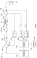
- FIG. 2 illustrates an example control system 200 that may be used to control the welding-type system 100 of FIG. 1 .
- the example control system 200 may be implemented by executing instructions (e.g., the instructions 125) via the processor 120 of the controller 112. However, in some examples, the carrier signal injection and measurement may be performed using the controller 134 in the wire feeder 104 (e.g., by execution of the instructions 125 by the processor(s) 120).
- the control system 200 includes a closed control loop 202, having a filter 204 (e.g., a proportional-integral (PI) filter), an amplifier 206, and a feedback loop 208.
- the example controller 112 further includes an impedance calculator 210, a frequency adjuster 212, and a waveform controller 214.
- the filter 204, the impedance calculator 210, the frequency adjuster 212, and/or the waveform controller 214 may be implemented by the controller 112 using instructions executed on a processor, programmable circuitry programmed to perform the corresponding operations, application-specific circuitry, and/or any other programmable and/or non-programmable circuitry configurations.
- the controller 112 inputs a current command i* to the closed control loop 202, from which current feedback is subtracted to provide a signal to the filter 204.
- the filter 204 generates a resultant voltage signal V ref based on the current command i* and the current feedback.
- the controller 112 injects a carrier voltage signal V I *sin( ⁇ I t) into the filtered voltage signal V ref .
- the carrier voltage signal has a predetermined voltage V i and a carrier frequency ⁇ i .
- the controller 112 selects the carrier frequency ⁇ i based on an estimated or measured time constant of the weld circuit 216 (e.g., L/R), and/or adjusts the carrier frequency ⁇ i via the frequency adjuster 212 as discussed below in more detail.
- the combined signal controls the power conversion circuitry 110 (e.g., an amplifier or PWM circuit) in combination with a DC link voltage (V dc ) to output a welding output signal 218 (e.g., welding current and welding voltage) to the weld cable 126 and the work cable 148.
- the DC link voltage V dc may be a bus voltage input to the power conversion circuitry 110.
- the controller 112 may input a voltage command, and/or the carrier signal is a current signal.
- the measured voltage V measure and the measured current I measure of the welding output signal 218 are filtered via notch filters 220 to isolate the carrier frequency ⁇ i , and provided to the impedance calculator 210.
- the impedance calculator 210 determines an impedance of the welding circuit based on the voltage and current signals V measure , I measure . In some examples, the impedance calculator 210 determines a phase difference V ⁇ I between the voltage and current of the welding output signal 218 at the carrier frequency ⁇ i to accurately determine the resistance of the weld circuit.
- the measured voltage V measure is measured using a voltage sensor 222 and the measured current I measure is measured using a current sensor 224.
- the current sensor 224 further provides the current feedback via the feedback loop 208.
- the example frequency adjuster 212 selects the carrier frequency ⁇ i to be at the corner frequency of the weld circuit 216 (e.g., based on the L/R time constant), which increases the change in the phase angle as the resistance and/or inductance of the weld circuit 216 changes, and provides increased accuracy in measuring the phase difference V ⁇ I.
- the frequency adjuster 212 may further monitor the phase difference V ⁇ I to determine whether the carrier frequency ⁇ i is within a predetermined range of the corner frequency for the weld circuit 216, which corresponds to a phase difference V ⁇ I of -45°.
- the frequency adjuster 212 may increase the carrier frequency ⁇ i (e.g., incrementally, proportionally, etc.). Conversely, if the phase difference V ⁇ I decreases below a lower threshold (e.g., -70°), the frequency adjuster 212 may decrease the carrier frequency ⁇ i (e.g., incrementally, proportionally, etc.).
- the example frequency adjuster 212 may adjust the carrier frequency ⁇ i using a control loop that generates a frequency error signal based on a difference between the phase difference V ⁇ I and a target phase difference (e.g., -45°). The frequency error signal may be filtered (e.g., via a proportional-integral filter) to mitigate the effects of rapid changes in impedance on the carrier frequency ⁇ i .
- the waveform controller 214 receives the phase difference V ⁇ I and controls the commanded current i* based on a selected waveform and the phase difference V ⁇ I. For example, if the waveform controller 214 determines that the phase difference V ⁇ I has changed from increasing to decreasing, changed from decreasing to increasing, changed by more than a threshold amount, reached a threshold value, or met any other predetermined criteria, the waveform controller 214 may adjust the commanded current i* to implement the selected waveform. For example, the waveform controller 214 may reduce the commanded current i* in response to detecting an indication of the clearing of a short circuit condition in the weld circuit 216 based on the impedance.
- the example control system 200 may include notch filters 221 to isolate the carrier voltage signal V i and/or reduce (e.g., prevent) filtering of the carrier voltage signal V i by the filter 204.
- the frequency adjuster 212 controls the notch filters 220 and 221 based on adjustments to the carrier frequency ⁇ i .
- FIG. 3A is a graph illustrating an example welding circuit resistance 302 during operation of the welding-type system 100 of FIG. 1 .
- the welding circuit resistance 302 may be based at least in part on the commanded current i* commanded by the waveform controller 214 of FIG. 2 .
- FIG. 3B is a graph illustrating an example voltage waveform 304 and a corresponding current waveform 306 of a signal V i injected into the control system 200 of FIG. 2 .
- the voltage and current waveforms 304, 306 are modulated at the carrier frequency ⁇ i .
- the voltage waveform 304 has a consistent magnitude, while the magnitude of the current waveform 306 increases and decreases inversely with the resistance 302 of the weld circuit 216 shown in FIG. 3A .
- FIG. 3C is a graph illustrating the current command 308 (e.g., the commanded current i* of FIG. 2 ) and the resulting output current 310 (e.g., the welding output signal 218) of the welding-type system 100 including the injected signal.
- the magnitude of the resulting output current 310 also changes based on the resistance 302 of the welding circuit 316.
- the impedance calculator 210, the frequency adjuster 212, and the waveform controller 214 may use the current magnitude instead of the phase difference V ⁇ I to control the control system 200.
- FIG. 3D is a graph of the phase difference 312 between the voltage and current of the injected signal V i .
- the phase difference 312 inversely correlates to the resistance 302 of the welding circuit 316.
- the waveform controller 214 can accurately estimate and/or predict the state of the welding arc.
- FIG. 4 illustrates another example control system 400 that may be used to control the welding-type system of FIG. 1 .
- the example control system 400 is similar to the control system 200 of FIG. 2 , and includes the filter 204, the amplifier 206, the feedback loop 208, the impedance calculator 210, the frequency adjuster 212, the waveform controller 214, and the weld circuit 216.
- the example control system 400 injects a current signal I i at the carrier frequency ⁇ i into the current command signal i*.
- the current signal Ii is also provided to the impedance calculator 210.
- the impedance calculator 210 further receives a measured voltage in the control system 400, which is filtered via a notch filter 220 to isolate the carrier frequency ⁇ i . Based on the injected current signal Ii and the measured voltage signal V measure , the impedance calculator 210 determines the phase difference V ⁇ I as discussed above.
- the example control system 400 may be advantageously used relatively high inductances and low resistances in the weld circuit 216.
- the carrier frequency ⁇ i will be a lower frequency than in the control system 200 of FIG. 2 (e.g., substantially below the current regulator bandwidth).
- the controller 112 may calculate the voltage resulting from the injected signal V i , I i based on the known injected signal V i , I i and the DC link voltage V dc .
- the controller 112 may determine an estimated voltage signal V ⁇ measure by multiplying the known injected signal V i , I i and the magnitude of the DC link voltage V dc .
- the impedance calculator 210 may then determine the phase difference V ⁇ I using the measured current signal I measure and the estimated voltage signal V ⁇ measure . Using the estimated voltage signal V ⁇ measure reduces the filtering involved in obtaining the voltage signal and substantially retains the accuracy.
- the present devices and/or methods may be realized in hardware, software, or a combination of hardware and software.
- the present methods and/or systems may be realized in a centralized fashion in at least one computing system, processors, and/or other logic circuits, or in a distributed fashion where different elements are spread across several interconnected computing systems, processors, and/or other logic circuits. Any kind of computing system or other apparatus adapted for carrying out the methods described herein is suited.
- a typical combination of hardware and software may be a processing system integrated into a welding power supply with a program or other code that, when being loaded and executed, controls the welding power supply such that it carries out the methods described herein.
- Another typical implementation may comprise an application specific integrated circuit or chip such as field programmable gate arrays (FPGAs), a programmable logic device (PLD) or complex programmable logic device (CPLD), and/or a system-on-a-chip (SoC).
- FPGAs field programmable gate arrays
- PLD programmable logic device
- CPLD complex programmable logic device
- SoC system-on-a-chip
- Some implementations may comprise a non-transitory machine-readable (e.g., computer readable) medium (e.g., FLASH memory, optical disk, magnetic storage disk, or the like) having stored thereon one or more lines of code executable by a machine, thereby causing the machine to perform processes as described herein.
- non-transitory machine readable medium is defined to include all types of machine readable storage media and to exclude propagating signals.
Landscapes
- Engineering & Computer Science (AREA)
- Physics & Mathematics (AREA)
- Plasma & Fusion (AREA)
- Mechanical Engineering (AREA)
- Theoretical Computer Science (AREA)
- Arc Welding Control (AREA)
Abstract
Disclosed example welding power supplies include: power conversion circuitry configured to convert input power to welding power; and control circuitry configured to: control the power conversion circuitry based on a control loop and a reference parameter; add a carrier signal to the control loop, the carrier signal having a carrier frequency; measure an impedance at an output of the power conversion circuitry based on the carrier frequency; and control the reference parameter based on the impedance.
Description
- The present application claims the benefit of
U.S. Patent Application Serial No. 63/583,678, filed September 19, 2023 U.S. Patent Application Serial No. 63/583,678 - This disclosure relates generally to welding systems and, more particularly, to systems and methods to monitor a welding arc.
- Conventional short circuit gas metal arc welding (GMAW), also referred to as metal inert gas (MIG) welding, is a welding process in which an electric arc forms between an electrode and pieces of metal that are to be welded. In some welding operations, specific waveforms are used to control the current and/or voltage to provide an improved welding result. Some such waveforms include rapid changes in voltage and/or current, and between arc states such as a short circuit and an arc state.
- Systems and methods to monitor a welding arc are disclosed, substantially as illustrated by and described in connection with at least one of the figures, as set forth more completely in the claims.
-
-
FIG. 1 is an illustration of an example welding-type system in accordance with aspects of this disclosure. -
FIG. 2 illustrates an example control system that may be used to control the welding-type system ofFIG. 1 . -
FIG. 3A is a graph illustrating an example welding circuit resistance during operation of the welding-type system ofFIG. 1 . -
FIG. 3B is a graph illustrating example voltage and current waveforms of a signal injected into the control system ofFIG. 2 . -
FIG. 3C is a graph illustrating the current command and the resulting output current of the welding-type system including the injected signal. -
FIG. 3D is a graph of the phase angle between the voltage and current of the injected signal. -
FIG. 4 illustrates another example control system that may be used to control the welding-type system ofFIG. 1 . - The figures are not necessarily to scale. Where appropriate, similar or identical reference numbers are used to refer to similar or identical components.
- Some welding control schemes benefit from predicting the state of the welding arc and/or other aspects of the weld. For example, predicting the moment of reignition of the welding arc following a short circuit is beneficial for reducing spatter and/or weld puddle disturbances. However, the welding arc is highly dynamic, and can be difficult to accurately predict in time to proactively respond to the prediction.
- Disclosed example systems and methods inject a carrier signal into the control system, and measures the current and voltage of the carrier signal to determine the impedance of the welding arc. Disclosed systems and methods respond to the impedance and/or changes in the impedance to predict the state of the arc. In some examples, an open-loop voltage signal is added to the voltage command in the current regulator of the control system. Alternatively, a current signal can be added to the current command input to the control system. Example systems and methods may then monitor a phase angle difference between the voltage and current of the carrier signal to determine the impedance, which is in turn used for controlling the welding process. Persistent excitation of the weld circuit with the carrier signal greatly improves the accuracy of the impedance measurement over time in disclosed example systems and methods.
- As used herein, the term "welding-type power" refers to power suitable for welding, plasma cutting, induction heating, CAC-A and/or hot wire welding/preheating (including laser welding and laser cladding). As used herein, the term "welding-type power supply" refers to any device capable of, when power is applied thereto, supplying welding, plasma cutting, induction heating, CAC-A and/or hot wire welding/preheating (including laser welding and laser cladding) power, including but not limited to inverters, converters, resonant power supplies, quasi-resonant power supplies, and the like, as well as control circuitry and other ancillary circuitry associated therewith.
- As used herein, a "weld voltage setpoint" refers to a voltage input to the power converter via a user interface, network communication, weld procedure specification, or other selection method.
- As used herein, a "circuit" includes any analog and/or digital components, power and/or control elements, such as a microprocessor, digital signal processor (DSP), software, and the like, discrete and/or integrated components, or portions and/or combinations thereof.
- Disclosed example welding power supplies include: power conversion circuitry configured to convert input power to welding power; and control circuitry configured to: control the power conversion circuitry based on a control loop and a reference parameter; add a carrier signal to the control loop, the carrier signal having a carrier frequency; measure an impedance at an output of the power conversion circuitry based on the carrier frequency; and control the reference parameter based on the impedance.
- In some example welding power supplies, the control circuitry is configured to predict a transition from a first phase of a welding control waveform to a second phase of the welding control waveform based on the impedance. In some example welding power supplies, the control circuitry is configured to detect a clearing of a short circuit condition based on the impedance. In some example welding power supplies, the control circuitry is configured to reduce the reference parameter in response to detecting an indication of the clearing of the short circuit condition based on the impedance, wherein the reference parameter includes a current reference.
- In some example welding power supplies, the control circuitry is configured to control the reference parameter based on a phase angle of the impedance. In some example welding power supplies, the control circuitry is configured to adjust the carrier frequency based on a phase angle of the impedance. In some example welding power supplies, the reference parameter is a current reference and the carrier signal is a voltage signal. In some example welding power supplies, the control circuitry is configured to implement a notch filter to mitigate the carrier signal within the control loop.
- Some example welding power supplies further include a current sensor, the control circuitry configured to measure the impedance using the current sensor. Some example welding power supplies further include a voltage sensor configured to measure an output voltage of the power conversion circuitry, in which the control circuitry is configured to measure the impedance using the voltage sensor. In some example welding power supplies, the control circuitry is configured to estimate an output voltage of the power conversion circuitry based on the carrier signal and a DC link voltage. In some example welding power supplies, the reference parameter is a voltage reference and the carrier signal is a current signal.
- Some other disclosed example welding power supplies include: power conversion circuitry configured to convert input power to welding power; and control circuitry configured to: control the power conversion circuitry based on a control loop and a reference parameter; add a carrier signal to the reference parameter, the carrier signal having a carrier frequency less than a control loop frequency; measure an impedance within the control loop based on the carrier frequency; and control the reference parameter based on the impedance.
- In some example welding power supplies, the control circuitry is configured to predict a transition from a first phase of a welding control waveform to a second phase of the welding control waveform based on the impedance. In some example welding power supplies, the control circuitry is configured to detect a clearing of a short circuit condition based on the impedance. In some example welding power supplies, the control circuitry is configured to reduce the reference parameter in response to detecting an indication of the clearing of the short circuit condition based on the impedance, in which the reference parameter includes a current reference.
- In some example welding power supplies, the control circuitry is configured to control the reference parameter based on a phase angle of the impedance. In some example welding power supplies, the control circuitry is configured to adjust the carrier frequency based on a phase angle of the impedance. In some example welding power supplies, the reference parameter is a current reference and the carrier signal is a current signal. Some example welding power supplies further include a current sensor, the control circuitry configured to measure the impedance using the current sensor.
- Turning now to the drawings,
FIG. 1 is a block diagram of anexample welding system 100 having a welding-type power supply 102, awire feeder 104, and awelding torch 106. Thewelding system 100 powers, controls, and supplies consumables to a welding application. In some examples, thepower supply 102 directly supplies input power to thewelding torch 106. Thewelding torch 106 may be a torch configured for shielded metal arc welding (SMAW, or stick welding), tungsten inert gas (TIG) welding, gas metal arc welding (GMAW), flux cored arc welding (FCAW), based on the desired welding application. In the illustrated example, thepower supply 102 is configured to supply power to thewire feeder 104, and thewire feeder 104 may be configured to route the input power to thewelding torch 106. In addition to supplying an input power, thewire feeder 104 may supply a filler metal to awelding torch 106 for various welding applications (e.g., GMAW welding, flux core arc welding (FCAW)). While theexample system 100 ofFIG. 1 includes a wire feeder 104 (e.g., for GMAW or FCAW welding), thewire feeder 104 may be replaced by any other type of remote accessory device, such as a stick welding and/or TIG welding remote control interface that provides stick and/or TIG welding. - The
power supply 102 receives primary power 108 (e.g., from the AC power grid, an engine/generator set, a battery, or other energy generating or storage devices, or a combination thereof), conditions the primary power, and provides an output power to one or more welding devices in accordance with demands of thesystem 100. The primary power 108 may be supplied from an offsite location (e.g., the primary power may originate from the power grid). Thepower supply 102 includespower conversion circuitry 110, which may include transformers, rectifiers, switches, and so forth, capable of converting the AC input power to AC and/or DC output power as dictated by the demands of the system 100 (e.g., particular welding processes and regimes). Thepower conversion circuitry 110 converts input power (e.g., the primary power 108) to welding-type power based on a weld voltage setpoint and outputs the welding-type power via a weld circuit. - In some examples, the
power conversion circuitry 110 is configured to convert the primary power 108 to both welding-type power and auxiliary power outputs. However, in other examples, thepower conversion circuitry 110 is adapted to convert primary power only to a weld power output. - The
power supply 102 includes acontroller 112 to control the operation of thepower supply 102. Thepower supply 102 also includes auser interface 114. Thecontroller 112, which is also referred to as "control circuitry," receives input from theuser interface 114, through which a user may choose a process and/or input desired parameters (e.g., voltages, currents, particular pulsed or non-pulsed welding regimes, and so forth). Theuser interface 114 may receive inputs using any input device, such as via a keypad, keyboard, buttons, touch screen, voice activation system, wireless device, etc. Furthermore, thecontroller 112 controls operating parameters based on input by the user as well as based on other current operating parameters. Specifically, theuser interface 114 may include adisplay 116 for presenting, showing, or indicating, information to an operator. Thecontroller 112 may also include interface circuitry for communicating data to other devices in thesystem 100, such as thewire feeder 104. For example, in some situations, thepower supply 102 wirelessly communicates with other welding devices within thewelding system 100. Further, in some situations, thepower supply 102 communicates with other welding devices using a wired connection, such as by using a network interface controller (NIC) to communicate data via a network (e.g., ETHERNET, 10baseT, 10base100, etc.). In the example ofFIG. 1 , thecontroller 112 communicates with thewire feeder 104 via the weld circuit via acommunications transceiver 118, as described below. - The
controller 112 includes at least one controller orprocessor 120 that controls the operations of thepower supply 102. Thecontroller 112 receives and processes multiple inputs associated with the performance and demands of thesystem 100. Theprocessor 120 may include one or more microprocessors, such as one or more "general-purpose" microprocessors, one or more special-purpose microprocessors and/or ASICS, and/or any other type of processing device. For example, theprocessor 120 may include one or more digital signal processors (DSPs). - The
example controller 112 includes one or more storage device(s) 123 and one or more memory device(s) 124. The storage device(s) 123 (e.g., nonvolatile storage) may include ROM, flash memory, a hard drive, and/or any other suitable optical, magnetic, and/or solid-state storage medium, and/or a combination thereof. Thestorage device 123 stores data (e.g., data corresponding to a welding application), instructions (e.g., software or firmware to perform welding processes), and/or any other appropriate data. Examples of stored data for a welding application include an attitude (e.g., orientation) of a welding torch, a distance between the contact tip and a workpiece, a voltage, a current, welding device settings, and so forth. - The
memory device 124 may include a volatile memory, such as random access memory (RAM), and/or a nonvolatile memory, such as read-only memory (ROM). Thememory device 124 and/or the storage device(s) 123 may store a variety of information and may be used for various purposes. For example, thememory device 124 and/or the storage device(s) 123 may store processor executable instructions 125 (e.g., firmware or software) for theprocessor 120 to execute. In addition, one or more control regimes for various welding processes, along with associated settings and parameters, may be stored in thestorage device 123 and/ormemory device 124, along with code configured to provide a specific output (e.g., initiate wire feed, enable gas flow, capture welding current data, detect short circuit parameters, determine amount of spatter) during operation. - In some examples, the welding power flows from the
power conversion circuitry 110 through aweld cable 126 to thewire feeder 104 and thewelding torch 106. Theexample weld cable 126 is attachable and detachable from weld studs at each of thepower supply 102 and the wire feeder 104 (e.g., to enable ease of replacement of theweld cable 126 in case of wear or damage). Furthermore, in some examples, welding data is provided with theweld cable 126 such that welding power and weld data are provided and transmitted together over theweld cable 126. Thecommunications transceiver 118 may be communicatively coupled to theweld cable 126 to communicate (e.g., send/receive) data over theweld cable 126. Thecommunications transceiver 118 may be implemented based on various types of power line communications methods and techniques. For example, thecommunications transceiver 118 may utilize IEEE standard P1901.2 to provide data communications over theweld cable 126. In this manner, theweld cable 126 may be utilized to provide welding power from thepower supply 102 to thewire feeder 104 and thewelding torch 106. Additionally or alternatively, acommunication cable 127 may be used to transmit and/or receive data communications between thecommunications transceiver 118 and asimilar communications transceiver 119 of thewire feeder 104. - The
example communications transceiver 118 includes areceiver circuit 121 and atransmitter circuit 122. Generally, thereceiver circuit 121 receives data transmitted by thewire feeder 104 and thetransmitter circuit 122 transmits data to thewire feeder 104. In some examples, thereceiver circuit 121 receives communication(s) via the weld circuit while weld current is flowing through the weld circuit (e.g., during a welding-type operation) and/or after the weld current has stopped flowing through the weld circuit (e.g., after a welding-type operation). - Example implementations of the
communications transceiver 118 are described inU.S. Patent No. 9,012,807 U.S. Patent No. 9,012,807 communications transceiver 118 may be used. - The
example wire feeder 104 also includes acommunications transceiver 119, which may be similar or identical in construction and/or function as thecommunications transceiver 118. - The
example power supply 102 includes avoltage monitor 160 and acurrent monitor 168. The voltage monitor 160 monitors an output voltage from the welding-type power supply 102. The output voltage may be controlled by thepower conversion circuitry 110, the touch detection circuitry 111, an external voltage source, current source, and/or load, and/or any other internal or external cause of voltage. Thecurrent monitor 168 monitors an output current. While the examplecurrent monitor 168 is illustrated monitoring the output current from thepower conversion circuitry 110, thecurrent monitor 168 may be configured to monitor any currents flowing through the output terminals of thepower supply 102 and/or for any particular circuits. For example, thecurrent monitor 168 may detect whether a current is flowing when the touch detection circuitry 111 is outputting a voltage and thepower conversion circuitry 110 is disabled. Theexample wire feeder 104 may also include avoltage monitor 162 to monitor an arc voltage (e.g., between a location close to the arc and a location on the workpiece). The voltage monitor 162 may be coupled to a point on thetorch 106, a point in thewire feeder 104, a point in thetorch cable 144, or any other location in electrical contact with the weld circuit. - In some examples, a
gas supply 128 provides shielding gases, such as argon, helium, carbon dioxide, and so forth, depending upon the welding application. The shielding gas flows to avalve 130, which controls the flow of gas, and if desired, may be selected to allow for modulating or regulating the amount of gas supplied to a welding application. Thevalve 130 may be opened, closed, or otherwise operated by thecontroller 112 to enable, inhibit, or control gas flow (e.g., shielding gas) through thevalve 130. Shielding gas exits thevalve 130 and flows through a cable 132 (which in some implementations may be packaged with the welding power output) to thewire feeder 104 which provides the shielding gas to the welding application. In some examples, thewelding system 100 does not include thegas supply 128, thevalve 130, and/or thecable 132. - In some examples, the
wire feeder 104 uses the welding power to power the various components in thewire feeder 104, such as to power awire feeder controller 134. As noted above, theweld cable 126 may be configured to provide or supply the welding power. Thepower supply 102 may also communicate with acommunications transceiver 119 of thewire feeder 104 using theweld cable 126 and thecommunications transceiver 118 disposed within thepower supply 102. In some examples, thecommunications transceiver 119 is substantially similar to thecommunications transceiver 118 of thepower supply 102. Thewire feeder controller 134 controls the operations of thewire feeder 104. In some examples, thewire feeder 104 uses thewire feeder controller 134 to detect whether thewire feeder 104 is in communication with thepower supply 102 and to detect a current welding process of thepower supply 102 if thewire feeder 104 is in communication with thepower supply 102. - A contactor 135 (e.g., high amperage relay) is controlled by the
wire feeder controller 134 and configured to enable or inhibit welding power to continue to flow to theweld cable 126 for the welding application. In some examples, thecontactor 135 is an electromechanical device. However, thecontactor 135 may be any other suitable device, such as a solid state device, and/or may be omitted when thepower supply 102 is configured to control the output of welding-type power to thetorch 106. Thecontroller 112 and/or thecontroller 134 may control thecontactor 135 to close and/or open to provide power to thetorch 106. Thewire feeder 104 includes afeed motor 136 that receives control signals from thewire feeder controller 134 to driverollers 138 that rotate to pull wire off a spool 140 of wire and feed the wire to thetorch 106. The wire is provided to the welding application through atorch cable 142. Likewise, thewire feeder 104 may provide the shielding gas from thecable 132 through thecable 142. The wire electrode, the shield gas, and the power from theweld cable 126 are bundled together in asingle torch cable 144 and/or individually provided to thewelding torch 106. - The
welding torch 106 delivers the wire, welding power, and/or shielding gas for a welding application. Thewelding torch 106 is used to establish a welding arc between thewelding torch 106 and aworkpiece 146. Awork cable 148 couples theworkpiece 146 to the power supply 102 (e.g., to the power conversion circuitry 110) to provide a return path for the weld current (e.g., as part of the weld circuit). Theexample work cable 148 attachable and/or detachable from thepower supply 102 for ease of replacement of thework cable 148. Thework cable 148 may be terminated with a clamp 150 (or another power connecting device), which couples thepower supply 102 to theworkpiece 146. - In operation, the
example controller 112 controls thepower conversion circuitry 110 based on a control loop and one or more reference parameter(s) (e.g., a weld voltage setpoint, a wire feed speed setpoint). The control loop receives voltage feedback (e.g., from thevoltage monitor 160, from the voltage monitor 162 via the communications transceiver 119) and/or current feedback (e.g., from the current monitor 168), and adjusts control values within the control loop based on the feedback. Thecontroller 112 may use a predetermined waveform (e.g., a controlled short circuit, a Regulated Metal Deposition (RMD™) waveform, a short arc waveform, etc.) in combination with the reference parameter(s) to control the output of thepower conversion circuitry 110. - In some welding operations and/or waveforms, the welding operation benefits from accurate estimation and/or prediction of the arc state. To more accurately predict the arc state, the
example controller 112 injects a carrier signal, having predetermined characteristics, into the control loop. Thecontroller 112 further monitors the characteristics of the carrier signal at an output of thepower conversion circuitry 110, at the location of the arc (e.g., at the torch 106), and/or at any other desired location, to measure a resistance of the arc. Thecontroller 112 may then use the resistance of the arc and/or a rate of change in the resistance of the arc to predict the present and/or future state of the arc. - The
controller 112 selects a frequency of the carrier signal based on characteristics of the welding circuit, such as resistance(s) and/or inductances of theweld cable 126, thetorch cable 144, and/or thework cable 148. In some examples, the characteristics of the welding circuit may be estimated and/or based on current and/or prior measurements. In some examples, thecontroller 112 adjusts the frequency of the carrier signal during operation to obtain a phase angle within a desired range. -
FIG. 2 illustrates anexample control system 200 that may be used to control the welding-type system 100 ofFIG. 1 . Theexample control system 200 may be implemented by executing instructions (e.g., the instructions 125) via theprocessor 120 of thecontroller 112. However, in some examples, the carrier signal injection and measurement may be performed using thecontroller 134 in the wire feeder 104 (e.g., by execution of theinstructions 125 by the processor(s) 120). - The
control system 200 includes aclosed control loop 202, having a filter 204 (e.g., a proportional-integral (PI) filter), anamplifier 206, and afeedback loop 208. Theexample controller 112 further includes animpedance calculator 210, afrequency adjuster 212, and awaveform controller 214. Thefilter 204, theimpedance calculator 210, thefrequency adjuster 212, and/or thewaveform controller 214 may be implemented by thecontroller 112 using instructions executed on a processor, programmable circuitry programmed to perform the corresponding operations, application-specific circuitry, and/or any other programmable and/or non-programmable circuitry configurations. - The
controller 112 inputs a current command i* to theclosed control loop 202, from which current feedback is subtracted to provide a signal to thefilter 204. Thefilter 204 generates a resultant voltage signal Vref based on the current command i* and the current feedback. - The
controller 112 injects a carrier voltage signal VI*sin(ωIt) into the filtered voltage signal Vref. The carrier voltage signal has a predetermined voltage Vi and a carrier frequency ωi. Thecontroller 112 selects the carrier frequency ωi based on an estimated or measured time constant of the weld circuit 216 (e.g., L/R), and/or adjusts the carrier frequency ωi via thefrequency adjuster 212 as discussed below in more detail. The combined signal (Vref + Vi) controls the power conversion circuitry 110 (e.g., an amplifier or PWM circuit) in combination with a DC link voltage (Vdc) to output a welding output signal 218 (e.g., welding current and welding voltage) to theweld cable 126 and thework cable 148. The DC link voltage Vdc may be a bus voltage input to thepower conversion circuitry 110. In some other examples, thecontroller 112 may input a voltage command, and/or the carrier signal is a current signal. - The measured voltage Vmeasure and the measured current Imeasure of the
welding output signal 218 are filtered vianotch filters 220 to isolate the carrier frequency ωi, and provided to theimpedance calculator 210. Theimpedance calculator 210 determines an impedance of the welding circuit based on the voltage and current signals Vmeasure, Imeasure. In some examples, theimpedance calculator 210 determines a phase difference V∠I between the voltage and current of thewelding output signal 218 at the carrier frequency ωi to accurately determine the resistance of the weld circuit. - In the example of
FIG. 2 , the measured voltage Vmeasure is measured using avoltage sensor 222 and the measured current Imeasure is measured using acurrent sensor 224. Thecurrent sensor 224 further provides the current feedback via thefeedback loop 208. - The
example frequency adjuster 212 selects the carrier frequency ωi to be at the corner frequency of the weld circuit 216 (e.g., based on the L/R time constant), which increases the change in the phase angle as the resistance and/or inductance of theweld circuit 216 changes, and provides increased accuracy in measuring the phase difference V∠I. Thefrequency adjuster 212 may further monitor the phase difference V∠I to determine whether the carrier frequency ωi is within a predetermined range of the corner frequency for theweld circuit 216, which corresponds to a phase difference V∠I of -45°. For example, if the phase difference V∠I increases above an upper threshold (e.g., -20°), thefrequency adjuster 212 may increase the carrier frequency ωi (e.g., incrementally, proportionally, etc.). Conversely, if the phase difference V∠I decreases below a lower threshold (e.g., -70°), thefrequency adjuster 212 may decrease the carrier frequency ωi (e.g., incrementally, proportionally, etc.). Alternatively, theexample frequency adjuster 212 may adjust the carrier frequency ωi using a control loop that generates a frequency error signal based on a difference between the phase difference V∠I and a target phase difference (e.g., -45°). The frequency error signal may be filtered (e.g., via a proportional-integral filter) to mitigate the effects of rapid changes in impedance on the carrier frequency ωi. - The
waveform controller 214 receives the phase difference V∠I and controls the commanded current i* based on a selected waveform and the phase difference V∠I. For example, if thewaveform controller 214 determines that the phase difference V∠I has changed from increasing to decreasing, changed from decreasing to increasing, changed by more than a threshold amount, reached a threshold value, or met any other predetermined criteria, thewaveform controller 214 may adjust the commanded current i* to implement the selected waveform. For example, thewaveform controller 214 may reduce the commanded current i* in response to detecting an indication of the clearing of a short circuit condition in theweld circuit 216 based on the impedance. - The
example control system 200 may includenotch filters 221 to isolate the carrier voltage signal Vi and/or reduce (e.g., prevent) filtering of the carrier voltage signal Vi by thefilter 204. In some examples, thefrequency adjuster 212 controls thenotch filters -
FIG. 3A is a graph illustrating an examplewelding circuit resistance 302 during operation of the welding-type system 100 ofFIG. 1 . Thewelding circuit resistance 302 may be based at least in part on the commanded current i* commanded by thewaveform controller 214 ofFIG. 2 . -
FIG. 3B is a graph illustrating anexample voltage waveform 304 and a correspondingcurrent waveform 306 of a signal Vi injected into thecontrol system 200 ofFIG. 2 . The voltage andcurrent waveforms FIG. 3B , thevoltage waveform 304 has a consistent magnitude, while the magnitude of thecurrent waveform 306 increases and decreases inversely with theresistance 302 of theweld circuit 216 shown inFIG. 3A . -
FIG. 3C is a graph illustrating the current command 308 (e.g., the commanded current i* ofFIG. 2 ) and the resulting output current 310 (e.g., the welding output signal 218) of the welding-type system 100 including the injected signal. As shown inFIG. 3C , the magnitude of the resulting output current 310 also changes based on theresistance 302 of the welding circuit 316. In some examples, theimpedance calculator 210, thefrequency adjuster 212, and thewaveform controller 214 may use the current magnitude instead of the phase difference V∠I to control thecontrol system 200. -
FIG. 3D is a graph of thephase difference 312 between the voltage and current of the injected signal Vi. As shown inFIGS. 3A and 3D , thephase difference 312 inversely correlates to theresistance 302 of the welding circuit 316. By monitoring thephase difference 312 via theimpedance calculator 210, thewaveform controller 214 can accurately estimate and/or predict the state of the welding arc. -
FIG. 4 illustrates anotherexample control system 400 that may be used to control the welding-type system ofFIG. 1 . Theexample control system 400 is similar to thecontrol system 200 ofFIG. 2 , and includes thefilter 204, theamplifier 206, thefeedback loop 208, theimpedance calculator 210, thefrequency adjuster 212, thewaveform controller 214, and theweld circuit 216. - Instead of injecting a voltage signal Vi, the
example control system 400 injects a current signal Ii at the carrier frequency ωi into the current command signal i*. The current signal Ii is also provided to theimpedance calculator 210. Theimpedance calculator 210 further receives a measured voltage in thecontrol system 400, which is filtered via anotch filter 220 to isolate the carrier frequency ωi. Based on the injected current signal Ii and the measured voltage signal Vmeasure, theimpedance calculator 210 determines the phase difference V∠I as discussed above. - The
example control system 400 may be advantageously used relatively high inductances and low resistances in theweld circuit 216. In such cases, the carrier frequency ωi will be a lower frequency than in thecontrol system 200 ofFIG. 2 (e.g., substantially below the current regulator bandwidth). - In some examples, instead of measuring the voltage signal Vmeasure, the
controller 112 may calculate the voltage resulting from the injected signal Vi, Ii based on the known injected signal Vi, Ii and the DC link voltage Vdc. For example, thecontroller 112 may determine an estimated voltage signal V̂measure by multiplying the known injected signal Vi, Ii and the magnitude of the DC link voltage Vdc. Theimpedance calculator 210 may then determine the phase difference V∠I using the measured current signal Imeasure and the estimated voltage signal V̂measure. Using the estimated voltage signal V̂measure reduces the filtering involved in obtaining the voltage signal and substantially retains the accuracy. - The present devices and/or methods may be realized in hardware, software, or a combination of hardware and software. The present methods and/or systems may be realized in a centralized fashion in at least one computing system, processors, and/or other logic circuits, or in a distributed fashion where different elements are spread across several interconnected computing systems, processors, and/or other logic circuits. Any kind of computing system or other apparatus adapted for carrying out the methods described herein is suited. A typical combination of hardware and software may be a processing system integrated into a welding power supply with a program or other code that, when being loaded and executed, controls the welding power supply such that it carries out the methods described herein. Another typical implementation may comprise an application specific integrated circuit or chip such as field programmable gate arrays (FPGAs), a programmable logic device (PLD) or complex programmable logic device (CPLD), and/or a system-on-a-chip (SoC). Some implementations may comprise a non-transitory machine-readable (e.g., computer readable) medium (e.g., FLASH memory, optical disk, magnetic storage disk, or the like) having stored thereon one or more lines of code executable by a machine, thereby causing the machine to perform processes as described herein. As used herein, the term "non-transitory machine readable medium" is defined to include all types of machine readable storage media and to exclude propagating signals.
- While the present method and/or system has been described with reference to certain implementations, it will be understood by those skilled in the art that various changes may be made and equivalents may be substituted without departing from the scope of the present method and/or system. In addition, many modifications may be made to adapt a particular situation or material to the teachings of the present disclosure without departing from its scope. For example, block and/or components of disclosed examples may be combined, divided, re-arranged, and/or otherwise modified. Therefore, the present method and/or system are not limited to the particular implementations disclosed. Instead, the present method and/or system will include all implementations falling within the scope of the appended claims, both literally and under the doctrine of equivalents.
- Various aspects of the present disclosure are provided in the following numbered clauses:
- Clause 1. A welding power supply, comprising:
- power conversion circuitry configured to convert input power to welding power; and
- control circuitry configured to:
- control the power conversion circuitry based on a control loop and a reference parameter;
- add a carrier signal to the control loop, the carrier signal having a carrier frequency;
- measure an impedance at an output of the power conversion circuitry based on the carrier frequency; and
- control the reference parameter based on the impedance.
- Clause 2. The welding power supply as defined in clause 1, wherein the control circuitry is configured to predict a transition from a first phase of a welding control waveform to a second phase of the welding control waveform based on the impedance.
- Clause 3. The welding power supply as defined in clause1, wherein the control circuitry is configured to detect a clearing of a short circuit condition based on the impedance.
- Clause 4. The welding power supply as defined in clause 3, wherein the control circuitry is configured to reduce the reference parameter in response to detecting an indication of the clearing of the short circuit condition based on the impedance, wherein the reference parameter comprises a current reference.
- Clause 5. The welding power supply as defined in clause 1, wherein the control circuitry is configured to control the reference parameter based on a phase angle of the impedance.
- Clause 6. The welding power supply as defined in clause 1, wherein the control circuitry is configured to adjust the carrier frequency based on a phase angle of the impedance.
- Clause 7. The welding power supply as defined in clause1, wherein the reference parameter is a current reference and the carrier signal is a voltage signal.
- Clause 8. The welding power supply as defined in clause 1, wherein the control circuitry is configured to implement a notch filter to mitigate the carrier signal within the control loop.
- Clause 9. The welding power supply as defined in clause 1, further comprising a current sensor, the control circuitry configured to measure the impedance using the current sensor.
- Clause 10. The welding power supply as defined in clause 9, further comprising a voltage sensor configured to measure an output voltage of the power conversion circuitry, the control circuitry configured to measure the impedance using the voltage sensor.
- Clause 11. The welding power supply as defined in clause 9, wherein the control circuitry is configured to estimate an output voltage of the power conversion circuitry based on the carrier signal and a DC link voltage.
- Clause 12. The welding power supply as defined in clause 1, wherein the reference parameter is a voltage reference and the carrier signal is a current signal.
- Clause 13. A welding power supply, comprising:
- power conversion circuitry configured to convert input power to welding power; and
- control circuitry configured to:
- control the power conversion circuitry based on a control loop and a reference parameter;
- add a carrier signal to the reference parameter, the carrier signal having a carrier frequency less than a control loop frequency;
- measure an impedance within the control loop based on the carrier frequency; and
- control the reference parameter based on the impedance.
- Clause 14. The welding power supply as defined in clause 13, wherein the control circuitry is configured to predict a transition from a first phase of a welding control waveform to a second phase of the welding control waveform based on the impedance.
- Clause 15. The welding power supply as defined in clause 13, wherein the control circuitry is configured to detect a clearing of a short circuit condition based on the impedance.
- Clause 16. The welding power supply as defined in clause15, wherein the control circuitry is configured to reduce the reference parameter in response to detecting an indication of the clearing of the short circuit condition based on the impedance, wherein the reference parameter comprises a current reference.
- Clause 17. The welding power supply as defined in clause 13, wherein the control circuitry is configured to control the reference parameter based on a phase angle of the impedance.
- Clause 18. The welding power supply as defined in clause 13, wherein the control circuitry is configured to adjust the carrier frequency based on a phase angle of the impedance.
- Clause 19. The welding power supply as defined in clause 13, wherein the reference parameter is a current reference and the carrier signal is a current signal.
- Clause 20. The welding power supply as defined in clause 13, further comprising a current sensor, the control circuitry configured to measure the impedance using the current sensor.
Claims (15)
- A welding power supply, comprising:power conversion circuitry configured to convert input power to welding power; andcontrol circuitry configured to:control the power conversion circuitry based on a control loop and a reference parameter;add a carrier signal to the control loop, the carrier signal having a carrier frequency;measure an impedance at an output of the power conversion circuitry based on the carrier frequency; andcontrol the reference parameter based on the impedance.
- The welding power supply as defined in claim 1, wherein the control circuitry is configured to predict a transition from a first phase of a welding control waveform to a second phase of the welding control waveform based on the impedance.
- The welding power supply as defined in claim 1, wherein the control circuitry is configured to detect a clearing of a short circuit condition based on the impedance,
optionally wherein the control circuitry is configured to reduce the reference parameter in response to detecting an indication of the clearing of the short circuit condition based on the impedance, wherein the reference parameter comprises a current reference. - The welding power supply as defined in claim 1, wherein the control circuitry is configured to control the reference parameter based on a phase angle of the impedance.
- The welding power supply as defined in claim 1, wherein the control circuitry is configured to adjust the carrier frequency based on a phase angle of the impedance.
- The welding power supply as defined in claim 1, wherein the reference parameter is a current reference and the carrier signal is a voltage signal.
- The welding power supply as defined in claim 1, wherein the control circuitry is configured to implement a notch filter to mitigate the carrier signal within the control loop.
- The welding power supply as defined in claim 1, further comprising a current sensor, the control circuitry configured to measure the impedance using the current sensor,optionally wherein the welding power supply further comprises a voltage sensor configured to measure an output voltage of the power conversion circuitry, the control circuitry configured to measure the impedance using the voltage sensor, oroptionally wherein the control circuitry is configured to estimate an output voltage of the power conversion circuitry based on the carrier signal and a DC link voltage.
- The welding power supply as defined in claim 1, wherein the reference parameter is a voltage reference and the carrier signal is a current signal.
- A welding power supply, comprising:power conversion circuitry configured to convert input power to welding power; andcontrol circuitry configured to:control the power conversion circuitry based on a control loop and a reference parameter;add a carrier signal to the reference parameter, the carrier signal having a carrier frequency less than a control loop frequency;measure an impedance within the control loop based on the carrier frequency; andcontrol the reference parameter based on the impedance.
- The welding power supply as defined in claim 10, wherein the control circuitry is configured to predict a transition from a first phase of a welding control waveform to a second phase of the welding control waveform based on the impedance.
- The welding power supply as defined in claim 10, wherein the control circuitry is configured to detect a clearing of a short circuit condition based on the impedance,
optionally wherein the control circuitry is configured to reduce the reference parameter in response to detecting an indication of the clearing of the short circuit condition based on the impedance, wherein the reference parameter comprises a current reference. - The welding power supply as defined in claim 10, wherein the control circuitry is configured to control the reference parameter based on a phase angle of the impedance.
- The welding power supply as defined in claim 10, wherein the control circuitry is configured to adjust the carrier frequency based on a phase angle of the impedance.
- The welding power supply as defined in claim 10, wherein the reference parameter is a current reference and the carrier signal is a current signal, or
wherein the welding power supply further comprises a current sensor, the control circuitry configured to measure the impedance using the current sensor.
Applications Claiming Priority (2)
| Application Number | Priority Date | Filing Date | Title |
|---|---|---|---|
| US202363583678P | 2023-09-19 | 2023-09-19 | |
| US18/830,076 US20250242427A1 (en) | 2023-09-19 | 2024-09-10 | Systems and methods to monitor a welding arc |
Publications (1)
| Publication Number | Publication Date |
|---|---|
| EP4527535A1 true EP4527535A1 (en) | 2025-03-26 |
Family
ID=92842977
Family Applications (1)
| Application Number | Title | Priority Date | Filing Date |
|---|---|---|---|
| EP24201205.2A Pending EP4527535A1 (en) | 2023-09-19 | 2024-09-18 | Systems and methods to monitor a welding arc |
Country Status (3)
| Country | Link |
|---|---|
| US (1) | US20250242427A1 (en) |
| EP (1) | EP4527535A1 (en) |
| MX (1) | MX2024011441A (en) |
Citations (4)
| Publication number | Priority date | Publication date | Assignee | Title |
|---|---|---|---|---|
| JPS59193767A (en) * | 1983-04-18 | 1984-11-02 | Matsushita Electric Ind Co Ltd | Arc welding equipment |
| US9012807B2 (en) | 2004-04-16 | 2015-04-21 | Illinois Tool Works Inc. | Remote wire feeder using binary phase shift keying to modulate communications of command/control signals to be transmitted over a weld cable |
| US20170095877A1 (en) * | 2015-10-06 | 2017-04-06 | Hypertherm, Inc. | Controlling Plasma Arc Torches and Related Systems and Methods |
| JP2017163680A (en) * | 2016-03-09 | 2017-09-14 | 株式会社ダイヘン | Welding power supply |
-
2024
- 2024-09-10 US US18/830,076 patent/US20250242427A1/en active Pending
- 2024-09-18 MX MX2024011441A patent/MX2024011441A/en unknown
- 2024-09-18 EP EP24201205.2A patent/EP4527535A1/en active Pending
Patent Citations (4)
| Publication number | Priority date | Publication date | Assignee | Title |
|---|---|---|---|---|
| JPS59193767A (en) * | 1983-04-18 | 1984-11-02 | Matsushita Electric Ind Co Ltd | Arc welding equipment |
| US9012807B2 (en) | 2004-04-16 | 2015-04-21 | Illinois Tool Works Inc. | Remote wire feeder using binary phase shift keying to modulate communications of command/control signals to be transmitted over a weld cable |
| US20170095877A1 (en) * | 2015-10-06 | 2017-04-06 | Hypertherm, Inc. | Controlling Plasma Arc Torches and Related Systems and Methods |
| JP2017163680A (en) * | 2016-03-09 | 2017-09-14 | 株式会社ダイヘン | Welding power supply |
Also Published As
| Publication number | Publication date |
|---|---|
| US20250242427A1 (en) | 2025-07-31 |
| MX2024011441A (en) | 2025-04-02 |
Similar Documents
| Publication | Publication Date | Title |
|---|---|---|
| US12337424B2 (en) | Systems and methods for automatic control of welding parameter output ranges | |
| EP4582210A2 (en) | Methods and apparatus to synergically control a welding-type output during a welding-type operation | |
| EP3711890B1 (en) | Systems and methods to start arc welding | |
| US12162102B2 (en) | Welding power supplies and user interfaces to control output polarity for welding power supplies | |
| US20250242427A1 (en) | Systems and methods to monitor a welding arc | |
| US12202081B2 (en) | Welding power supplies and method for completed circuit testing process | |
| EP4556150A2 (en) | Methods and apparatus to control tig welding | |
| EP4048470B1 (en) | Welding-type system, and method to determine a total heat input to a welding-type operation involving multiple energy sources | |
| EP3865241B1 (en) | Systems and methods to control welding processes using a voltage-controlled control loop | |
| EP4021674B1 (en) | Welding power supply with a wire preheating system | |
| US20220362875A1 (en) | Systems and methods to start a welding process | |
| US11883911B2 (en) | Welding power supplies, wire feeders, and systems to measure a weld cable impedance | |
| EP4552782A1 (en) | Welding power supplies to compensate a weld voltage via communications over a weld circuit | |
| EP3681663A1 (en) | Systems, methods, and apparatus to reduce cast in a welding wire |
Legal Events
| Date | Code | Title | Description |
|---|---|---|---|
| PUAI | Public reference made under article 153(3) epc to a published international application that has entered the european phase |
Free format text: ORIGINAL CODE: 0009012 |
|
| STAA | Information on the status of an ep patent application or granted ep patent |
Free format text: STATUS: THE APPLICATION HAS BEEN PUBLISHED |
|
| AK | Designated contracting states |
Kind code of ref document: A1 Designated state(s): AL AT BE BG CH CY CZ DE DK EE ES FI FR GB GR HR HU IE IS IT LI LT LU LV MC ME MK MT NL NO PL PT RO RS SE SI SK SM TR |
|
| STAA | Information on the status of an ep patent application or granted ep patent |
Free format text: STATUS: REQUEST FOR EXAMINATION WAS MADE |
|
| 17P | Request for examination filed |
Effective date: 20250923 |