EP4527518A1 - Method for manufacturing metallic member, mold, and metallic member - Google Patents
Method for manufacturing metallic member, mold, and metallic member Download PDFInfo
- Publication number
- EP4527518A1 EP4527518A1 EP23807415.7A EP23807415A EP4527518A1 EP 4527518 A1 EP4527518 A1 EP 4527518A1 EP 23807415 A EP23807415 A EP 23807415A EP 4527518 A1 EP4527518 A1 EP 4527518A1
- Authority
- EP
- European Patent Office
- Prior art keywords
- metal sheet
- corner
- sheet
- punch
- counter
- Prior art date
- Legal status (The legal status is an assumption and is not a legal conclusion. Google has not performed a legal analysis and makes no representation as to the accuracy of the status listed.)
- Pending
Links
Images







Classifications
-
- B—PERFORMING OPERATIONS; TRANSPORTING
- B21—MECHANICAL METAL-WORKING WITHOUT ESSENTIALLY REMOVING MATERIAL; PUNCHING METAL
- B21D—WORKING OR PROCESSING OF SHEET METAL OR METAL TUBES, RODS OR PROFILES WITHOUT ESSENTIALLY REMOVING MATERIAL; PUNCHING METAL
- B21D22/00—Shaping without cutting, by stamping, spinning, or deep-drawing
- B21D22/20—Deep-drawing
- B21D22/22—Deep-drawing with devices for holding the edge of the blanks
-
- B—PERFORMING OPERATIONS; TRANSPORTING
- B21—MECHANICAL METAL-WORKING WITHOUT ESSENTIALLY REMOVING MATERIAL; PUNCHING METAL
- B21D—WORKING OR PROCESSING OF SHEET METAL OR METAL TUBES, RODS OR PROFILES WITHOUT ESSENTIALLY REMOVING MATERIAL; PUNCHING METAL
- B21D24/00—Special deep-drawing arrangements in, or in connection with, presses
- B21D24/04—Blank holders; Mounting means therefor
-
- B—PERFORMING OPERATIONS; TRANSPORTING
- B21—MECHANICAL METAL-WORKING WITHOUT ESSENTIALLY REMOVING MATERIAL; PUNCHING METAL
- B21D—WORKING OR PROCESSING OF SHEET METAL OR METAL TUBES, RODS OR PROFILES WITHOUT ESSENTIALLY REMOVING MATERIAL; PUNCHING METAL
- B21D28/00—Shaping by press-cutting; Perforating
- B21D28/02—Punching blanks or articles with or without obtaining scrap; Notching
- B21D28/14—Dies
-
- B—PERFORMING OPERATIONS; TRANSPORTING
- B21—MECHANICAL METAL-WORKING WITHOUT ESSENTIALLY REMOVING MATERIAL; PUNCHING METAL
- B21D—WORKING OR PROCESSING OF SHEET METAL OR METAL TUBES, RODS OR PROFILES WITHOUT ESSENTIALLY REMOVING MATERIAL; PUNCHING METAL
- B21D28/00—Shaping by press-cutting; Perforating
- B21D28/02—Punching blanks or articles with or without obtaining scrap; Notching
- B21D28/16—Shoulder or burr prevention, e.g. fine-blanking
-
- B—PERFORMING OPERATIONS; TRANSPORTING
- B21—MECHANICAL METAL-WORKING WITHOUT ESSENTIALLY REMOVING MATERIAL; PUNCHING METAL
- B21D—WORKING OR PROCESSING OF SHEET METAL OR METAL TUBES, RODS OR PROFILES WITHOUT ESSENTIALLY REMOVING MATERIAL; PUNCHING METAL
- B21D28/00—Shaping by press-cutting; Perforating
- B21D28/24—Perforating, i.e. punching holes
- B21D28/34—Perforating tools; Die holders
-
- B—PERFORMING OPERATIONS; TRANSPORTING
- B21—MECHANICAL METAL-WORKING WITHOUT ESSENTIALLY REMOVING MATERIAL; PUNCHING METAL
- B21D—WORKING OR PROCESSING OF SHEET METAL OR METAL TUBES, RODS OR PROFILES WITHOUT ESSENTIALLY REMOVING MATERIAL; PUNCHING METAL
- B21D35/00—Combined processes according to or processes combined with methods covered by groups B21D1/00 - B21D31/00
- B21D35/002—Processes combined with methods covered by groups B21D1/00 - B21D31/00
- B21D35/005—Processes combined with methods covered by groups B21D1/00 - B21D31/00 characterized by the material of the blank or the workpiece
-
- B—PERFORMING OPERATIONS; TRANSPORTING
- B21—MECHANICAL METAL-WORKING WITHOUT ESSENTIALLY REMOVING MATERIAL; PUNCHING METAL
- B21D—WORKING OR PROCESSING OF SHEET METAL OR METAL TUBES, RODS OR PROFILES WITHOUT ESSENTIALLY REMOVING MATERIAL; PUNCHING METAL
- B21D28/00—Shaping by press-cutting; Perforating
- B21D28/24—Perforating, i.e. punching holes
- B21D28/26—Perforating, i.e. punching holes in sheets or flat parts
Definitions
- the present invention relates to a method of manufacturing a metallic member, a press tool, and a metallic member.
- JP 2021-133391 A discloses a cutting tool including a fixed tool portion and a movable tool portion.
- the movable tool portion is constructed to cut a metal sheet by performing a first cutting step, where the clearance between the fixed and movable tool portions is c + ⁇ c ( ⁇ c >0), and a subsequent second cutting step, where the clearance between the fixed and movable tool portions is c.
- JP 2017-87294 A discloses a method of cutting a surface-treated steel sheet using a tool including a die and a punch that provide a clearance of 1 to 20 % of the sheet thickness, where the corner of at least one of the die or punch is provided with a radius of curvature that is not smaller than 0.12 times the sheet thickness of the surface-treated steel sheet.
- JP 2021-133391 A , JP 2017-87294 A , and JP 2009-287082 A each discloses a particular tool construction specifically created to leave a section of the material's plating layer that goes around onto the cut edge surface.
- these methods leave such a go-around section of the plating layer from one direction, which means that the amount of the plating component that can be supplied onto the cut edge surface is limited.
- a press tool includes: a punch; a counter-pad located opposite to the punch, a metal sheet representing a workpiece being positioned between the punch and the counter-pad; a sheet holder located adjacent to the same side of the metal sheet as the punch as determined along a thickness direction of the sheet and positioned to surround the punch along in-plane directions of the metal sheet; and a die located adjacent to the same side of the metal sheet as the counter-pad as determined along the thickness direction of the sheet and positioned to surround the counter-pad along in-plane directions of the metal sheet, the sheet holder including a projecting portion at an inner circumferential edge of a face facing the metal sheet, the projecting portion of the sheet holder including a corner at an inner circumference, the corner having a radius of curvature R1, the radius of curvature R1 being not smaller than 0.2 mm.
- a method of manufacturing a metallic member according to one embodiment of the present invention is a method of manufacturing a metallic member by using a press tool to stamp a metal sheet having front and back faces covered with a coating layer, the press tool including:
- FIG. 1 is a cross-sectional view of a press tool 20 according to a first embodiment of the present invention, schematically illustrating its construction.
- the press tool 20 is used for stamping a metal sheet.
- the press tool 20 includes a punch 21, a counter-pad 22, a sheet holder (i.e., upper die part) 23, and a die (i.e., lower die part) 24.
- the counter-pad 22 is located opposite to the punch 21, a metal sheet 10 representing a workpiece being positioned between the punch and counter-pad.
- the sheet holder 23 is located adjacent to the same side of the metal sheet 10 as the punch 21 as determined along the thickness direction of the sheet (i.e., z-direction of FIG.
- the punch 21 and counter-pad 22 include faces 21a and 22a, respectively, that face the metal sheet 10. Both the face 21a and the face 22a are flat surfaces parallel to the metal sheet 10.
- the faces 21a and 22a have the same planar shape (shape in an xy-plane).
- the faces 21a and 22a may have any planar shape, and may be circular, elliptical or rectangular, for example.
- the sheet holder 23 includes a projecting portion 231 at an inner circumferential edge of the face 23a facing the metal sheet 10.
- the inner circumferential edge of the face 23a means its circumferential edge adjacent to the punch 21.
- the face 24a of the die 24 that faces the metal sheet 10 is a flat surface parallel to the metal sheet 10.
- FIG. 2 is a cross-sectional view of a portion of the sheet holder 23.
- the projecting portion 231 includes a corner 231a at its inner circumference, the corner having a radius of curvature R1.
- the inner circumference of the projecting portion 231 means the side of the projecting portion 231 that is adjacent to the punch 21.
- the radius of curvature R1 of the corner 231a is preferably not smaller than 0.2 mm.
- the radius of curvature R1 is more preferably not smaller than 0.3 mm, yet more preferably not smaller than 0.5 mm, still more preferably not smaller than 0.8 mm, and yet more preferably not smaller than 1.0 mm.
- the radius of curvature R1 of the corner 231a is preferably not smaller than 0.10 times the thickness of the metal sheet 10, i.e., workpiece.
- a lower limit of the radius of curvature R1 is more preferably 0.20 times the thickness of the metal sheet 10, and yet more preferably 0.30 times the thickness of the metal sheet 10.
- An upper limit of the radius of curvature R1 is preferably 0.40 times the thickness of the metal sheet 10.
- the height of the projecting portion 231, h1 is preferably not smaller than 0.25 times the thickness of the metal sheet 10, i.e., workpiece.
- a lower limit of the height h1 is more preferably 0.30 times the thickness of the metal sheet 10, and yet more preferably 0.50 times the thickness of the metal sheet 10.
- An upper limit of the height h1 is preferably 1.00 times the thickness of the metal sheet 10.
- the side of the projecting portion 231 opposite to the corner 231a may have any shape.
- the projecting portion 231 has an inclined portion 231b constituting its side opposite to the corner 231a.
- the inclined portion 231b is shaped so as to expand toward the outer circumference (i.e., in directions away from the punch 21) as it goes closer to the face 23a.
- the projecting portion 231 includes such an inclined portion 231b, the durability of the projecting portion 231 is improved.
- the inclined portion 231b may have a shape represented by a straight line, as shown in FIG. 2 , or may have a shape represented by a curved line, such as the inclined portion 231Ab shown in FIG. 3 .
- the surface-plated metal sheet is a Zn-based plated steel sheet.
- a Zn-based plating acts as a sacrificial corrosion protection for the steel sheet, i.e., base material. This prevents corrosion initiating at exposed base material at the cut edge surface resulting from the shearing, thereby further increasing the corrosion resistance of the produced metallic member.
- the Zn-based plating may be hot-dip galvanizing, galvannealing, Zn-Ni-based plating, Zn-Al-based plating, Zn-Mg-based plating, or Zn-Al-Mg-based plating, for example.
- the sheet thickness of the surface-plated metal sheet is 1.0 to 6.0 mm, for example.
- FIG. 7 is an enlarged schematic cross-sectional view of the projecting portion 231 and nearby portions.
- a recess 10b is formed in the metal sheet 10 and, at the same time, a go-around section of the plating layer 10a is left on a wall of the recess 10b.
- a go-around section of the plating layer 10a will be left on that one of the two walls 10b1 and 10b2 of the recess 10b which is adjacent to the corner 231a, i.e., wall 10b1.
- This wall 10b1 is located inward of (i.e., further toward the center of the punch 21 than) the surface of the projecting portion 231 as determined along in-plane directions of the metal sheet 10 (i.e., xy-in-plane directions). In other words, a small gap is formed between the wall 10b1 and projecting portion 231. This is because portions of the material pushed in by the projecting portion 231 move toward the center of the punch 21 due to plastic flow.
- FIG. 7 shows an implementation where a go-around section of the plating layer 10a is also left on the wall 10b2 adjacent to the inclined portion 231b; in other implementations, no go-around section of the plating layer 10a may be left on the wall 10b2.
- the die 24 may be moved to stamp the metal sheet 10. Specifically, with the metal sheet 10 sandwiched between the punch 21 and counter-pad 22, the die 24 may be moved closer to the punch 21 to stamp the metal sheet 10. Alternatively, both the punch 21 and die 24 may be moved to stamp the metal sheet 10.
- the metal sheet 10 is separated into a metallic member 11 and remainder 119.
- the portion of the sheet sandwiched between the punch 21 and counter-pad 22 provides the metallic member 11.
- a go-around section of the plating layer 10a from one surface of the metal sheet 10 i.e., surface in contact with the counter-pad 22
- steps S2 and S3 may be performed as a single step by employing a double-action press or equipment capable of independently driving the punch 21 and sheet holder 23. Nevertheless, it is preferable that step S2 and step S3 are performed separately because this will allow the use of equipment with a simpler construction.
- simple construction may be provided where, at step S2, the press is lowered to perform recess formation using the sheet holder 23 alone and, at step S3, pressure is applied to the sheet holder 23 using a spring, for example, and the punch 21 is lowered to perform stamping.
- step S2 the step of pushing the projecting portion 231 of the sheet holder 23 into the metal sheet 10
- step S3 the step of moving the punch 21 and die 24 closer to each other to stamp the metal sheet 10
- FIG. 9 is a cross-sectional view of a metallic member 11 according to one embodiment of the present invention, schematically illustrating its construction.
- the metallic member 11 is formed by stamping a surface-plated metal sheet.
- the metallic member 11 includes a cut edge surface 111 formed through the stamping.
- the metallic member 11 includes a first surface 112 and a second surface 113 opposite to the first surface 112.
- the first and second surfaces 112 and 113 may have any planar shape (shape in an xy-plane).
- the first and second surfaces 112 and 113 are covered with a plating layer 10a.
- the plating layer 10a is derived from the plating layer of the material, i.e., surface-plated metal sheet.
- the cut edge surface 111 includes a sheared surface 111a, a recessed surface 111b, and an undercut contiguous to the recessed surface 111b, 111e.
- the recessed surface 111b being covered with the plating layer 10a, it is preferable that not less than 50 % of the total area of the recessed surface 111b and the undercut 111e contiguous to the recessed surface 111b is covered with the plating layer 10a.
- d /( t1+t2 ) is not less than 75 %.
- the entire recessed surface 111b is covered with the plating layer 10a.
- the undercut 111d contiguous to the sheared surface 111a is entirely covered with the plating layer 10a. At least a portion of the sheared surface 111a is covered with the plating layer 10a. Typically, the fracture surface 111c is not covered with the plating layer 10a.
- the plating layer 10a covering the sheared surface 111a, recessed surface 111b and undercuts 111d and 111e is derived from the plating layer of the material, i.e., surface-plated metal sheet.
- the plating layer 10a covering the sheared surface 111a, recessed surface 111b and undercut 111d and the plating layer 10a covering the first and second surfaces 112 and 113 are one and the same plating layer.
- the press tool 20 the method of the manufacturing a metallic member, and the metallic member 11 according to the first embodiment of the present invention have been described.
- the sheet holder 23 of the press tool 20 includes a projecting portion 231 at the inner circumferential edge of the face 23a facing the metal sheet 10.
- the projecting portion 231 includes a corner 231a at its inner circumference, the corner having a radius of curvature R1 ( FIG. 2 ).
- a recess 10b FIG. 7
- a go-around section of the plating layer 10a is left on a wall of the recess 10b.
- the press tool 20 according to the present embodiment and the method of manufacturing a metallic member according to the present embodiment are capable of supplying the plating layer 10a from both sides of the cut edge surface 111 arranged in the thickness direction (i.e., z-direction).
- the plate layer 10a may be supplied not only from the second surface 113, but also from the first surface 112.
- at least a portion of the recessed surface 111b may be covered with the plating layer 10a. This provides a metallic member 11 with a cut edge surface 111 with improved corrosion resistance.
- FIG. 10 is a cross-sectional view of a press tool 30 according to a second embodiment of the present invention, schematically illustrating its construction.
- the press tool 30 includes a die 34, which replaces the die 24 ( FIG. 1 ) of the press tool 20 of the first embodiment.
- the die 34 includes a projecting portion 341 at an inner circumferential edge of the of the face 34a facing the metal sheet 10.
- the inner circumferential edge of the face 34a means its circumferential edge adjacent to the counter-pad 22.
- FIG. 11 is a cross-sectional view of a portion of the die 34.
- the die 34 includes a corner 341a at its inner circumference, the corner having a radius of curvature R2 .
- the inner circumference of the projecting portion 341 means the side of the projecting portion 341 that is adjacent to the counter-pad 22.
- the radius of curvature R2 of the corner 341a has the same preferable ranges as the radius of curvature R1 ( FIG. 2 ) of the corner 231a of the projecting portion 231 of the sheet holder 23.
- the radii of curvature R1 and R2 may be equal, or may be different.
- the height h2 of the projecting portion 341 has the same preferable ranges as the height h1 ( FIG. 2 ) of the projecting portion 231 of the sheet holder 23.
- the heights h1 and h2 may be equal, or may be different.
- a method of manufacturing a metallic member according to the present embodiment uses the above-described press tool 30 to stamp a surface-plated metal sheet to produce a metallic member.
- the manufacturing method includes the step of placing a metal sheet 10 on the counter-pad 22 and die 34, the step of pushing the projecting portion 231 of the sheet holder 23 and the projecting portion 341 of the die 34 into the metal sheet 10, and the step of moving the punch 21 and die 34 closer to each other to stamp the metal sheet 10.
- the various steps will be described below with reference to FIGS. 12 to 14 .
- a metal sheet 10 is placed on the counter-pad 22 and die 34 (see FIG. 12 ).
- the top and bottom of the press tool 30 i.e., the arrangement in the z-direction
- the metal sheet 10 is placed on the punch 21 and sheet holder 23 before being worked.
- the projecting portion 231 of the sheet holder 23 and the projecting portion 341 of the die 34 are pushed into the metal sheet 10 (see FIG. 13 ).
- the punch 21 and counter-pad 22 are caused to sandwich the metal sheet 10 to hold the metal sheet 10.
- the sheet holder 23 and die 34 are moved closer to each other to push the projecting portion 231 of the sheet holder 23 and the projecting portion 341 of the die 34 into the metal sheet 10.
- one of the sheet holder 23 and die 34 may be fixed and only the other one may be moved.
- the pressures applied to the punch 21 and counter-pad 22 may be controlled appropriately to enable the projecting portion 231 of the sheet holder 23 and the projecting portion 341 of the die 34 to be pushed into the metal sheet 10.
- the punch 21 and die 34 are moved closer to each other to stamp the metal sheet 10 (see FIG. 14 ).
- the metal sheet 10 is separated into a metallic member 12 and remainder 129.
- the portion of the sheet sandwiched between the punch 21 and counter-pad 22 provides the metallic member 12.
- FIG. 15 is a cross-sectional view of a metallic member 12 according to one embodiment of the present invention, schematically illustrating its construction.
- the metallic member 12 is formed by stamping a surface-plated metal sheet.
- the metallic member 12 includes a cut edge surface 121 formed through stamping.
- the metallic member 12 includes a first surface 122 and a second surface 123.
- the first and second surfaces 122 and 123 are covered with a plating layer 10a.
- the cut edge surface 121 includes a sheared surface 121a, a recessed surface 121b, and an undercut contiguous to the recessed surface 121b, 121e.
- the cut edge surface 121 further includes a fracture surface 121c, a second recessed surface 121d, and an undercut contiguous to the second recessed surface 121d, 121f.
- the fracture surface 121c is located between the sheared surface 121a and recessed surface 121b.
- the second recessed surface 121d is located contiguous to the side of the sheared surface 121a opposite to that adjacent to the recessed surface 121b.
- the sheared surface 121a is located between the recessed surface 121b and the second recessed surface 121d.
- the cut edge surface 121 may not include a fracture surface 121c.
- Each of the recessed surface 121b and second recessed surface 121d is a curved surface of a shape that protrudes inwardly with respect to the member.
- the amount of sinking W2 of the recessed surface 121b and the amount of sinking W3 of the second recessed surface 121d have the same ranges as the amount of sinking W1 ( FIG. 9 ) of the recessed surface 111b of the metallic member 11. It is to be noted that the amount of sinking W3 of the second recessed surface 121d tends to be smaller than the amount of sinking W2 of the recessed surface 121b.
- the recessed surface 121b is covered with the plating layer 10a. This improves the corrosion resistance of the cut edge surface 121.
- the preferable proportions of the total area of the recessed surface 121b and undercut 121e covered with the plating layer 10a and other associated features are the same as for the metallic member 11.
- the undercut 121f contiguous to the second recessed surface 121d is entirely covered with the plating layer 10a. At least a portion of the second recessed surface 121d is covered with the plating layer 10a.
- the sheared surface 121a may be entirely covered, partially covered, or not covered at all, with the plating layer 10a.
- the fracture surface 121c is not covered with the plating layer 10a.
- the press tool 30, the method of the manufacturing a metallic member, and the metallic member 12 according to the second embodiment of the present invention have been described.
- the projecting portions 231 and 341 are pushed into the metal sheet 10 to supply the plating layer 10a from both sides of the metal sheet 10 arranged in the thickness direction.
- the predetermined radius of curvature R2 of the corner 341a of the projecting portion 341 allows a larger amount of the plating layer 10a to provide a go-around section on the cut edge surface 121. This provides a metallic member 12 having a cut edge surface 121 with improved corrosion resistance.
- FIG. 16 is a cross-sectional view of a press tool 40 according to a third embodiment of the present invention, schematically illustrating its construction.
- the press tool 40 includes a die 44, which replaces the die 24 ( FIG. 1 ) of the press tool 20 of the first embodiment.
- FIG. 17 is a cross-sectional view of a portion of the die 44.
- the face 44a of the die 44 that faces the metal sheet 10 is a flat surface parallel to the metal sheet 10.
- the die 44 includes a double corner at its inner circumference. A used herein, the inner circumference of the die 44 means the side of the die adjacent to the counter-pad 22.
- the double corner includes a first sub-corner 441 and a second sub-corner 442.
- the second sub-corner 442 is located farther from the metal sheet 10 than the first sub-corner 441 is as measured in the thickness direction of the metal sheet 10 (i.e., z-direction), and located closer to the counter-pad 22 than the first sub-corner 441 is as measured in in-plane directions of the metal sheet 10 (i.e., xy-in-plane directions).
- the step height sh1 of the double corner is preferably larger than zero times and not larger than 0.50 times the thickness of the metal sheet 10, i.e., workpiece.
- the step height sh1 is defined as the distance from the face 44a to the topmost point of the second sub-corner 442 (i.e., point closest to the face 44a) as measured in the z-direction.
- a lower limit of the step height sh1 is preferably 0.10 times the thickness of the metal sheet 10, and more preferably 0.20 times.
- the metallic member 15 has the same construction as the metallic member 12 ( FIG. 15 ) of the second embodiment except that it has a different planar shape (shape in an xy-plane). Specifically, the metallic member 15 is formed by stamping a surface-plated metal sheet, and includes a cut edge surface formed through the stamping. This cut edge surface includes a sheared surface and recessed surfaces, where at least portions of the recessed surfaces are covered with the plating layer 10a.
- the height h1 ( FIG. 2 ) of the projecting portion 231 of the sheet holder 23 was 1.6 mm, and the radius of curvature R1 of the corner 231a was 0.9 mm. Further, for analysis of a simulation of the press tool 30 ( FIG. 10 ), the height h2 ( FIG. 11 ) of the projecting portion 341 of the die 34 was 1.6 mm, and the radius of curvature R2of the corner 341a was 0.9 mm. For analysis of a simulation of the press tool 40 ( FIG. 16 ), the radius of curvature Rp1 ( FIG.
- dots simulating the plating layer were set on the sheet surface and their movements were tracked to estimate the distance of coating with plating.
- the dimensions of the areas covered with the plating layer as measured in the thickness direction of the surface-plated metal sheet were denoted by d1 and d2, respectively, and their sum d1+d2 was divided by the sheet thickness T, (( d1+d2 )/ T ), which was treated as the proportion of coating with plating.
Landscapes
- Engineering & Computer Science (AREA)
- Mechanical Engineering (AREA)
- Shaping Metal By Deep-Drawing, Or The Like (AREA)
- Laminated Bodies (AREA)
Abstract
Description
- The present invention relates to a method of manufacturing a metallic member, a press tool, and a metallic member.
- Steel members of automobiles and buildings are usually produced through press working. When a corrosion-resistant steel member needs to be produced, a material in the form of cold-rolled steel sheet or hot-rolled steel sheet is pressed and then provided with paint and/or plating. Providing painting and/or plating steps after pressing increases work time and/or costs.
- To solve this problem, a material in the form of plated steel sheet may be pressed. However, if a plated steel sheet is subjected to a press-working process that involves cutting, such as stamping, the plating layer is severed at the cut edge surface, exposing base steel. If the base steel at the cut edge surface remains exposed, corrosion initiates at the cut edge surface. Addressing this requires an additional step for plating the cut edge surface at which base steel is exposed, which increases work time and costs.
-
JP 2021-133391 A -
JP 2017-87294 A -
JP 2009-287082 A -
JP 2020-32437 A - One known precision shearing process that provides a smooth cut edge surface is the "opposite-die shearing method" (see, for example,
JP H6-182461 A JP 2000-210731 A JP 2005-14062 A -
- Patent Document 1:
JP 2021-133391 A - Patent Document 2:
JP 2017-87294 A - Patent Document 3:
JP 2009-287082 A - Patent Document 4:
JP 2020-32437 A - Patent Document 5:
JP H6-182461 A - Patent Document 6:
JP 2000-210731 A - Patent Document 7:
JP 2005-14062 A -
JP 2021-133391 A JP 2017-87294 A JP 2009-287082 A - A problem to be solved by the present invention is to provide a method of manufacturing a metallic member having a cut edge surface with improved corrosion resistance, a press tool capable of manufacturing a metallic member having a cut edge surface with improved corrosion resistance, and a metallic member having a cut edge surface with improved corrosion resistance.
- A method of manufacturing a metallic member according to one embodiment of the present invention is a method of manufacturing a metallic member by using a press tool to stamp a metal sheet having front and back faces covered with a coating layer, the press tool including: a punch; a counter-pad located opposite to the punch, the metal sheet being positioned between the punch and the counter-pad; a sheet holder located adjacent to the same side of the metal sheet as the punch as determined along a thickness direction of the sheet and positioned to surround the punch along in-plane directions of the metal sheet; and a die located adjacent to the same side of the metal sheet as the counter-pad as determined along the thickness direction of the sheet and positioned to surround the counter-pad along in-plane directions of the metal sheet, the sheet holder including a projecting portion at an inner circumferential edge of a face facing the metal sheet, the projecting portion of the sheet holder including a corner at an inner circumference, the corner having a radius of curvature R1, the radius of curvature R1 being not smaller than 0.10 times a thickness of the metal sheet, the manufacturing method including: pushing the projecting portion of the sheet holder into the metal sheet; and moving the punch and the die closer to each other to stamp the metal sheet.
- A method of manufacturing a metallic member according to one embodiment of the present invention is a method of manufacturing a metallic member by using a press tool to stamp a metal sheet having front and back faces covered with a coating layer, the press tool including: a punch; a counter-pad located opposite to the punch, the metal sheet being positioned between the punch and the counter-pad; a sheet holder located adjacent to the same side of the metal sheet as the punch as determined along a thickness direction of the sheet and positioned to surround the punch along in-plane directions of the metal sheet; and a die located adjacent to the same side of the metal sheet as the counter-pad as determined along the thickness direction of the sheet and positioned to surround the counter-pad along in-plane directions of the metal sheet, the punch including a projecting portion at a circumferential edge of a face facing the metal sheet, the projecting portion of the punch including a corner at an outer circumference, the corner having a radius of curvature R3, the radius of curvature R3 being not smaller than 0.10 times a thickness of the metal sheet, the manufacturing method including: pushing the projecting portion of the punch into the metal sheet; and moving the counter-pad and the sheet holder closer to each other to stamp the metal sheet.
- A press tool according to one embodiment of the present invention includes: a punch; a counter-pad located opposite to the punch, a metal sheet representing a workpiece being positioned between the punch and the counter-pad; a sheet holder located adjacent to the same side of the metal sheet as the punch as determined along a thickness direction of the sheet and positioned to surround the punch along in-plane directions of the metal sheet; and a die located adjacent to the same side of the metal sheet as the counter-pad as determined along the thickness direction of the sheet and positioned to surround the counter-pad along in-plane directions of the metal sheet, the sheet holder including a projecting portion at an inner circumferential edge of a face facing the metal sheet, the projecting portion of the sheet holder including a corner at an inner circumference, the corner having a radius of curvature R1, the radius of curvature R1 being not smaller than 0.2 mm.
- A press tool according to one embodiment of the present invention includes: a punch; a counter-pad located opposite to the punch, a metal sheet representing a workpiece being positioned between the punch and the counter-pad; a sheet holder located adjacent to the same side of the metal sheet as the punch as determined along a thickness direction of the sheet and positioned to surround the punch along in-plane directions of the metal sheet; and a die located adjacent to the same side of the metal sheet as the counter-pad as determined along the thickness direction of the sheet and positioned to surround the counter-pad along in-plane directions of the metal sheet, the punch including a projecting portion at a circumferential edge of a face facing the metal sheet, the projecting portion of the punch including a corner at an outer circumference, the corner having a radius of curvature R3, the radius of curvature R3 being not smaller than 0.2 mm.
- A metallic member according to one embodiment of the present invention is a metallic member formed by stamping a metal sheet having front and back faces covered with a coating layer, including a cut edge surface formed by the stamping, the cut edge surface including: a sheared surface; and a recessed surface represented by a curved surface having a shape protruding inwardly with respect to the member, at least a portion of the recessed surface being covered with the coating layer.
- A method of manufacturing a metallic member according to one embodiment of the present invention is a method of manufacturing a metallic member by using a press tool to stamp a metal sheet having front and back faces covered with a coating layer,
the press tool including: - a punch;
- a counter-pad located opposite to the punch, the metal sheet being positioned between the punch and the counter-pad;
- a sheet holder located adjacent to the same side of the metal sheet as the punch as determined along a thickness direction of the sheet and positioned to surround the punch along in-plane directions of the metal sheet; and
- a die located adjacent to the same side of the metal sheet as the counter-pad as determined along the thickness direction of the sheet and positioned to surround the counter-pad along in-plane directions of the metal sheet,
- the press tool further including the following construction A) or B):
- A) the sheet holder including a projecting portion at an inner circumferential edge of a face facing the metal sheet, the projecting portion of the sheet holder including a corner at an inner circumference, the corner having a radius of curvature R1, the radius of curvature R1 being not smaller than 0.10 times a thickness of the metal sheet, or
- B) the punch including a projecting portion at a circumferential edge of a face facing the metal sheet, the projecting portion of the punch including a corner at an outer circumference, the corner having a radius of curvature R3, the radius of curvature R3 being not smaller than 0.10 times a thickness of the metal sheet,
- the manufacturing method including:
- pushing the projecting portion of the sheet holder into the metal sheet; and
- stamping the metal sheet.
- A press tool according to one embodiment of the present invention includes:
- a punch;
- a counter-pad located opposite to the punch, a metal sheet representing a workpiece being positioned between the punch and the counter-pad;
- a sheet holder located adjacent to the same side of the metal sheet as the punch as determined along a thickness direction of the sheet and positioned to surround the punch along in-plane directions of the metal sheet; and
- a die located adjacent to the same side of the metal sheet as the counter-pad as determined along the thickness direction of the sheet and positioned to surround the counter-pad along in-plane directions of the metal sheet,
- the press tool further including the following construction A) or B):
- A) the sheet holder including a projecting portion at an inner circumferential edge of a face facing the metal sheet, the projecting portion of the sheet holder including a corner at an inner circumference, the corner having a radius of curvature R1, the radius of curvature R1 being not smaller than 0.2 mm, or
- B) the punch including a projecting portion at a circumferential edge of a face facing the metal sheet, the projecting portion of the punch including a corner at an outer circumference, the corner having a radius of curvature R3, the radius of curvature R3 being not smaller than 0.2 mm.
- The present invention provides a metallic member having a cut edge surface with improved corrosion resistance.
-
- [
FIG. 1] FIG. 1 is a cross-sectional view of a press tool according to a first embodiment of the present invention, schematically illustrating its construction. - [
FIG. 2] FIG. 2 is a cross-sectional view of a portion of the sheet holder of the press tool ofFIG. 1 . - [
FIG. 3] FIG. 3 is a cross-sectional view of a variation of the sheet holder of the press tool ofFIG. 1 . - [
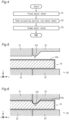
FIG. 4] FIG. 4 is a flow chart of a method of manufacturing a metallic member according to one embodiment of the present invention. - [
FIG. 5] FIG. 5 is a cross-sectional view schematically illustrating a moment during the manufacture of a metallic member. - [
FIG. 6] FIG. 6 is a cross-sectional view schematically illustrating a moment during the manufacture of a metallic member. - [
FIG. 7] FIG. 7 is an enlarged schematic cross-sectional view of the projecting portion and nearby portions. - [
FIG. 8] FIG. 8 is a cross-sectional view schematically illustrating a moment during the manufacture of a metallic member. - [
FIG. 9] FIG. 9 is a cross-sectional view of a metallic member according to one embodiment of the present invention, schematically illustrating its construction. - [
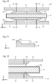
FIG. 10] FIG. 10 is a cross-sectional view of a press tool according to a second embodiment of the present invention, schematically illustrating its construction. - [
FIG. 11] FIG. 11 is a cross-sectional view of a portion of the die of the press tool ofFIG. 10 . - [
FIG. 12] FIG. 12 is a cross-sectional view schematically illustrating a moment during the manufacture of a metallic member. - [
FIG. 13] FIG. 13 is a cross-sectional view schematically illustrating a moment during the manufacture of a metallic member. - [
FIG. 14] FIG. 14 is a cross-sectional view schematically illustrating a moment during the manufacture of a metallic member. - [
FIG. 15] FIG. 15 is a cross-sectional view of a metallic member according to one embodiment of the present invention, schematically illustrating its construction. - [
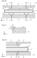
FIG. 16] FIG. 16 is a cross-sectional view of a press tool according to a third embodiment of the present invention, schematically illustrating its construction. - [
FIG. 17] FIG. 17 is a cross-sectional view of a portion of the die of the press tool ofFIG. 16 . - [
FIG. 18] FIG. 18 is a cross-sectional view schematically illustrating a moment during the manufacture of a metallic member. - [
FIG. 19] FIG. 19 is a cross-sectional view schematically illustrating a moment during the manufacture of a metallic member. - [
FIG. 20] FIG. 20 is a cross-sectional view schematically illustrating a moment during the manufacture of a metallic member. - [
FIG. 21] FIG. 21 is a cross-sectional view of a metallic member according to one embodiment of the present invention, schematically illustrating its construction. - [
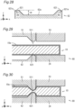
FIG. 22] FIG. 22 is a cross-sectional view of a press tool according to a fourth embodiment of the present invention, schematically illustrating its construction. - [
FIG. 23] FIG. 23 is a cross-sectional view of a portion of the punch of the press tool ofFIG. 22 . - [
FIG. 24] FIG. 24 is a cross-sectional view schematically illustrating a moment during the manufacture of a metallic member. - [
FIG. 25] FIG. 25 is a cross-sectional view schematically illustrating a moment during the manufacture of a metallic member. - [
FIG. 26] FIG. 26 is a cross-sectional view schematically illustrating a moment during the manufacture of a metallic member. - [
FIG. 27] FIG. 27 is a cross-sectional view of a press tool according to a fifth embodiment of the present invention, schematically illustrating its construction. - [
FIG. 28] FIG. 28 is a cross-sectional view of a portion of the counter-pad of the press tool ofFIG. 27 . - [
FIG. 29] FIG. 29 is a cross-sectional view schematically illustrating a moment during the manufacture of a metallic member. - [
FIG. 30] FIG. 30 is a cross-sectional view schematically illustrating a moment during the manufacture of a metallic member. - [
FIG. 31] FIG. 31 is a cross-sectional view schematically illustrating a moment during the manufacture of a metallic member. - [
FIG. 32] FIG. 32 is a cross-sectional view of a press tool according to a sixth embodiment of the present invention, schematically illustrating its construction. - [
FIG. 33] FIG. 33 is a cross-sectional view of a portion of the counter-pad of the press tool ofFIG. 32 . - [
FIG. 34] FIG. 34 is a cross-sectional view schematically illustrating a moment during the manufacture of a metallic member. - [
FIG. 35] FIG. 35 is a cross-sectional view schematically illustrating a moment during the manufacture of a metallic member. - [
FIG. 36] FIG. 36 is a cross-sectional view schematically illustrating a moment during the manufacture of a metallic member. - [
FIG. 37] FIG. 37 schematically illustrates the distribution of the plating layer found when the projecting portion of the sheet holder has been pushed into the metal sheet, calculated by CAE. - [
FIG. 38] FIG. 38 is a graph showing the relationship between the radius of curvature R1 and the distance of coating with plating, d. - [
FIG. 39] FIG. 39 illustrates plating coverage. - [
FIG. 40] FIG. 40 shows plating coverage obtained by CAE. - Now, embodiments of the present invention will be described in detail with reference to the drawings. The same or corresponding components in the drawings are labeled with the same reference numerals, and their description will not be repeated. The size ratios between the components shown in the drawings do not necessary represent the actual size ratios.
-
FIG. 1 is a cross-sectional view of apress tool 20 according to a first embodiment of the present invention, schematically illustrating its construction. Thepress tool 20 is used for stamping a metal sheet. Thepress tool 20 includes apunch 21, a counter-pad 22, a sheet holder (i.e., upper die part) 23, and a die (i.e., lower die part) 24. The counter-pad 22 is located opposite to thepunch 21, ametal sheet 10 representing a workpiece being positioned between the punch and counter-pad. Thesheet holder 23 is located adjacent to the same side of themetal sheet 10 as thepunch 21 as determined along the thickness direction of the sheet (i.e., z-direction ofFIG. 1 ), and positioned to surround thepunch 21 along in-plane directions of the metal sheet 10 (i.e., xy-in-plane directions ofFIG. 1 ). Thedie 24 is located adjacent to the same side of themetal sheet 10 as the counter-pad 22 as determined along the thickness direction of the sheet and is positioned to surround the counter-pad 22 along in-plane directions of themetal sheet 10. - The
punch 21 andcounter-pad 22 includefaces metal sheet 10. Both theface 21a and theface 22a are flat surfaces parallel to themetal sheet 10. Thefaces faces - A clearance CL of a predetermined size is provided between the
punch 21 andsheet holder 23. Similarly, a clearance CL of a predetermined size is provided between the counter-pad 22 and die 24. Preferably, the clearance CL has a generally constant size across the entire outer circumference of thepunch 21 orcounter-pad 22. - The
sheet holder 23 includes a projectingportion 231 at an inner circumferential edge of theface 23a facing themetal sheet 10. As used herein, the inner circumferential edge of theface 23a means its circumferential edge adjacent to thepunch 21. - The
face 24a of the die 24 that faces themetal sheet 10 is a flat surface parallel to themetal sheet 10. -
FIG. 2 is a cross-sectional view of a portion of thesheet holder 23. The projectingportion 231 includes acorner 231a at its inner circumference, the corner having a radius of curvature R1. As used herein, the inner circumference of the projectingportion 231 means the side of the projectingportion 231 that is adjacent to thepunch 21. - The radius of curvature R1 of the
corner 231a is preferably not smaller than 0.2 mm. The radius of curvature R1 is more preferably not smaller than 0.3 mm, yet more preferably not smaller than 0.5 mm, still more preferably not smaller than 0.8 mm, and yet more preferably not smaller than 1.0 mm. Further, the radius of curvature R1 of thecorner 231a is preferably not smaller than 0.10 times the thickness of themetal sheet 10, i.e., workpiece. A lower limit of the radius of curvature R1 is more preferably 0.20 times the thickness of themetal sheet 10, and yet more preferably 0.30 times the thickness of themetal sheet 10. An upper limit of the radius of curvature R1 is preferably 0.40 times the thickness of themetal sheet 10. - The height of the projecting
portion 231, h1, is preferably not smaller than 0.25 times the thickness of themetal sheet 10, i.e., workpiece. A lower limit of the height h1 is more preferably 0.30 times the thickness of themetal sheet 10, and yet more preferably 0.50 times the thickness of themetal sheet 10. An upper limit of the height h1 is preferably 1.00 times the thickness of themetal sheet 10. - The side of the projecting
portion 231 opposite to thecorner 231a may have any shape. In the implementation ofFIG. 2 , the projectingportion 231 has aninclined portion 231b constituting its side opposite to thecorner 231a. Theinclined portion 231b is shaped so as to expand toward the outer circumference (i.e., in directions away from the punch 21) as it goes closer to theface 23a. As the projectingportion 231 includes such aninclined portion 231b, the durability of the projectingportion 231 is improved. It will be understood that theinclined portion 231b may have a shape represented by a straight line, as shown inFIG. 2 , or may have a shape represented by a curved line, such as the inclined portion 231Ab shown inFIG. 3 . - Next, a method of manufacturing a metallic member according to one embodiment of the present invention will be described. The method of manufacturing a metallic member according to the present embodiment uses the above-described
press tool 20 to stamp a metal sheet having front and back faces covered with a coating layer (hereinafter referred to as "surface-coated metal sheet") to produce a metallic member. - Although not limiting, the base material of the surface-coated metal sheet may be steel, copper, a copper alloy, aluminum, or an aluminum alloy, for example. The manufacturing method according to the present embodiment is particularly suitable for implementations where the base material of the surface-coated metal sheet is steel. This is because steel is prone to rust and, as such, providing corrosion resistance to steel has a significant advantage. The coating layer may be a plating layer, a paint layer, or a resin layer, for example. The coated metal sheet is typically a plated steel sheet. The plated steel sheet may be a Zn-based plated steel sheet or an Al-based plated steel sheet, for example. The following description discusses a plating layer as an example of a coating layer and a surface-plated metal sheet as an example of a surface-coated metal sheet.
- More preferably, the surface-plated metal sheet is a Zn-based plated steel sheet. A Zn-based plating acts as a sacrificial corrosion protection for the steel sheet, i.e., base material. This prevents corrosion initiating at exposed base material at the cut edge surface resulting from the shearing, thereby further increasing the corrosion resistance of the produced metallic member. Although not limiting, the Zn-based plating may be hot-dip galvanizing, galvannealing, Zn-Ni-based plating, Zn-Al-based plating, Zn-Mg-based plating, or Zn-Al-Mg-based plating, for example.
- Although not limiting, the sheet thickness of the surface-plated metal sheet is 1.0 to 6.0 mm, for example.
- The thickness of the plating layer of the surface-plated metal sheet (i.e., thickness as measured at one face of the sheet; the same applies hereinafter) is preferably not smaller than 15 µm. If the thickness of the plating layer is too small, the plating layer may be insufficient for covering the cut edge surface, in which case corrosion resistance may not be provided to the cut edge surface. A lower limit of the thickness of the plating layer of the surface-plated metal sheet is more preferably 30 µm. Although not limiting, an upper limit of the thickness of the plating layer of the surface-plated metal sheet is 150 µm, for example.
-
FIG. 4 is a flow chart of a method of manufacturing a metallic member according to one embodiment of the present invention. The manufacturing method includes: a step in which a surface-plated metal sheet (hereinafter simply referred to as "metal sheet 10") is placed on the counter-pad 22 and die 24 (step S1); a step in which the projectingportion 231 of thesheet holder 23 is pushed into the metal sheet 10 (step S2); and a step in which thepunch 21 and die 24 are moved closer to each other to stamp the metal sheet 10 (step S3). - The various steps will be described below with reference to
FIGS. 5 to 8 . All of these drawings are schematic views. As stated above, the size ratios between the components shown in the drawings do not necessary represent the actual size ratios (the same applies toFIGS. 1 to 3 andFIGS. 9 sqq.). - The
metal sheet 10 is placed on the counter-pad 22 and die 24 (step S1; seeFIG. 5 ). Themetal sheet 10 has front and back faces covered with aplating layer 10a.FIG. 5 and other drawings show implementations where the edge surfaces of themetal sheet 10 are also covered with theplating layer 10a; in other implementations, the edge surfaces of themetal sheet 10 may not be covered with theplating layer 10a. - The projecting
portion 231 of thesheet holder 23 is pushed into the metal sheet 10 (step S2; seeFIG. 6 ). For example, a press, not shown, may be used to apply pressures of the same magnitude to thepunch 21 andcounter-pad 22 to sandwich themetal sheet 10 and thus hold themetal sheet 10. With the sheet kept in this state, thedie 24 is fixed in position and thesheet holder 23 is moved closer to the die 24 to push the projectingportion 231 of thesheet holder 23 into themetal sheet 10. In other implementations, instead of applying pressures of the same magnitude to thepunch 21 andcounter-pad 22, one of thepunch 21 andcounter-pad 22 may be fixed in position and, with this one kept in this state, pressure may be applied to the other one to sandwich themetal sheet 10. -
FIG. 7 is an enlarged schematic cross-sectional view of the projectingportion 231 and nearby portions. As the projectingportion 231 is pushed in, arecess 10b is formed in themetal sheet 10 and, at the same time, a go-around section of theplating layer 10a is left on a wall of therecess 10b. At this time, as thecorner 231a of the projectingportion 231 has a predetermined radius of curvature R1, a go-around section of theplating layer 10a will be left on that one of the two walls 10b1 and 10b2 of therecess 10b which is adjacent to thecorner 231a, i.e., wall 10b1. - This wall 10b1 is located inward of (i.e., further toward the center of the
punch 21 than) the surface of the projectingportion 231 as determined along in-plane directions of the metal sheet 10 (i.e., xy-in-plane directions). In other words, a small gap is formed between the wall 10b1 and projectingportion 231. This is because portions of the material pushed in by the projectingportion 231 move toward the center of thepunch 21 due to plastic flow. -
FIG. 7 shows an implementation where a go-around section of theplating layer 10a is also left on the wall 10b2 adjacent to theinclined portion 231b; in other implementations, no go-around section of theplating layer 10a may be left on the wall 10b2. - The
punch 21 and die 24 are moved closer to each other to stamp the metal sheet 10 (step S3; seeFIG. 8 ). For example, with the die 24 fixed in position, pressure is applied to thesheet holder 23 such that thesheet holder 23 and die 24 sandwich themetal sheet 10 and thus hold themetal sheet 10. With the sheet kept in this state, thepunch 21 is moved closer to the die 24 to stamp themetal sheet 10. At this time, a pressure may be applied to the counter-pad 22 that is lower than the pressure applied to thepunch 21 to support themetal sheet 10 from below. - Alternatively, in lieu of fixing the die 24 in position and applying pressure to the
sheet holder 23, themetal sheet 10 may be sandwiched by fixing thesheet holder 23 in position and, with the sheet holder kept in this state, applying pressure to thedie 24, or by applying pressures of the same magnitude to thesheet holder 23 and die 24. - Alternatively, in lieu of moving the
punch 21, thedie 24 may be moved to stamp themetal sheet 10. Specifically, with themetal sheet 10 sandwiched between thepunch 21 andcounter-pad 22, thedie 24 may be moved closer to thepunch 21 to stamp themetal sheet 10. Alternatively, both thepunch 21 and die 24 may be moved to stamp themetal sheet 10. - As a result, the
metal sheet 10 is separated into ametallic member 11 andremainder 119. According to the present embodiment, the portion of the sheet sandwiched between thepunch 21 andcounter-pad 22 provides themetallic member 11. At this time, a go-around section of theplating layer 10a from one surface of the metal sheet 10 (i.e., surface in contact with the counter-pad 22) is left on thecut edge surface 111 of themetallic member 11. - It will be understood that steps S2 and S3 may be performed as a single step by employing a double-action press or equipment capable of independently driving the
punch 21 andsheet holder 23. Nevertheless, it is preferable that step S2 and step S3 are performed separately because this will allow the use of equipment with a simpler construction. For example, simple construction may be provided where, at step S2, the press is lowered to perform recess formation using thesheet holder 23 alone and, at step S3, pressure is applied to thesheet holder 23 using a spring, for example, and thepunch 21 is lowered to perform stamping. - The above description relates to an implementation where the
metal sheet 10 is placed on the counter-pad 22 and die 24 before working themetal sheet 10. In other implementations, the top and bottom of the press tool 20 (i.e., the arrangement in the z-direction) may be reversed, where themetal sheet 10 is placed on thepunch 21 andsheet holder 23 before being worked. In such implementations, too, the step of pushing the projectingportion 231 of thesheet holder 23 into the metal sheet 10 (step S2) and the step of moving thepunch 21 and die 24 closer to each other to stamp the metal sheet 10 (step S3) may be performed in the same manner. -
FIG. 9 is a cross-sectional view of ametallic member 11 according to one embodiment of the present invention, schematically illustrating its construction. Themetallic member 11 is formed by stamping a surface-plated metal sheet. Themetallic member 11 includes acut edge surface 111 formed through the stamping. - In addition to the
cut edge surface 111, themetallic member 11 includes afirst surface 112 and asecond surface 113 opposite to thefirst surface 112. The first andsecond surfaces second surfaces plating layer 10a. Theplating layer 10a is derived from the plating layer of the material, i.e., surface-plated metal sheet. - The
cut edge surface 111 includes a shearedsurface 111a, a recessedsurface 111b, and an undercut contiguous to the recessedsurface - The
cut edge surface 111 further includes afracture surface 111c and an undercut contiguous to the shearedsurface 111a (i.e., second undercut), 111d. As determined along the thickness direction of the metallic member 11 (i.e., z-direction), thefracture surface 111c is located between thesheared surface 111a and recessedsurface 111b. As determined along the thickness direction of the metallic member 11 (i.e., z-direction), the undercut 111d is located contiguous to the side of the shearedsurface 111a opposite to that adjacent to the recessedsurface 111b. In other words, as determined along the thickness direction of the metallic member 11 (i.e., z-direction), the shearedsurface 111a is located between the recessedsurface 111b and undercut 111d. - Depending on the working conditions and other factors, the
cut edge surface 111 may not include afracture surface 111c. - The recessed
surface 111b is formed by the step of pushing the projectingportion 231 into the metal sheet 10 (i.e. step S2 inFIG. 4 ). Each of the undercut 111d and undercut 111e is a curved surface that protrudes outwardly with respect to the member, whereas the recessedsurface 111b is a curved surface of a shape that protrudes inwardly with respect to the member. - The recessed
surface 111b is recessed by an amount of sinking W1 with respect to the shearedsurface 111a. The amount of sinking W1 is defined as, in a cross section of themetallic member 11, the distance between the tangent to the shearedsurface 111a and the inwardmost point on the recessedsurface 111b. The amount of sinking W1 may be, for example, 0.01 to 0.15 times the thickness of themetallic member 11. A lower limit of the amount of sinking W1 is preferably 0.02 times the thickness of themetallic member 11. An upper limit of the amount of sinking W1 is preferably 0.10 times the thickness of themetallic member 11. - According to the present embodiment, at least a portion of the recessed
surface 111b is covered with theplating layer 10a. This improves the corrosion resistance of thecut edge surface 111. - In addition to at least a portion of the recessed
surface 111b being covered with theplating layer 10a, it is preferable that not less than 50 % of the total area of the recessedsurface 111b and the undercut 111e contiguous to the recessedsurface 111b is covered with theplating layer 10a. In more detail, it is preferable that d/(t1+t2) is not less than 0.5 (i.e., not less than 50 %), where t1 and t2 are the dimensions of the recessedsurface 111b and undercut 111e, respectively, as measured in the thickness direction of themetal sheet 10, and dis the dimension of that portion of the total area of the recessedsurface 111b and undercut 111e which is covered with theplating layer 10a as measured in the thickness direction of themetal sheet 10. The determination as to whether a given portion is covered with theplating layer 10a may be based on measurements on thecut edge surface 111 using an energy dispersive X-ray analyzer (EDX), for example. - More preferably, d/(t1+t2) is not less than 75 %. Most preferably, the entire recessed
surface 111b is covered with theplating layer 10a. - Typically, the undercut 111d contiguous to the sheared
surface 111a is entirely covered with theplating layer 10a. At least a portion of the shearedsurface 111a is covered with theplating layer 10a. Typically, thefracture surface 111c is not covered with theplating layer 10a. - As is the case with the
plating layer 10a covering the first andsecond surfaces plating layer 10a covering the shearedsurface 111a, recessedsurface 111b and undercuts 111d and 111e is derived from the plating layer of the material, i.e., surface-plated metal sheet. Thus, theplating layer 10a covering the shearedsurface 111a, recessedsurface 111b and undercut 111d and theplating layer 10a covering the first andsecond surfaces - The
press tool 20, the method of the manufacturing a metallic member, and themetallic member 11 according to the first embodiment of the present invention have been described. Thesheet holder 23 of thepress tool 20 includes a projectingportion 231 at the inner circumferential edge of theface 23a facing themetal sheet 10. The projectingportion 231 includes acorner 231a at its inner circumference, the corner having a radius of curvature R1 (FIG. 2 ). As this projectingportion 231 is pushed into themetal sheet 10, arecess 10b (FIG. 7 ) is formed in themetal sheet 10 and, at the same time, a go-around section of theplating layer 10a is left on a wall of therecess 10b. As thecorner 231a of the projectingportion 231 has a predetermined radius of curvature R1, a go-around section of theplating layer 10a is left on that one of the two walls 10b1 and 10b2 of therecess 10b which is adjacent to thecorner 231a, i.e., wall 10b1. The wall 10b1 corresponds to the recessedsurface 111b (FIG. 9 ) of themetallic member 11. At least a portion of the recessedsurface 111b is covered with theplating layer 10a. - The
press tool 20 according to the present embodiment and the method of manufacturing a metallic member according to the present embodiment are capable of supplying theplating layer 10a from both sides of thecut edge surface 111 arranged in the thickness direction (i.e., z-direction). In other words, theplate layer 10a may be supplied not only from thesecond surface 113, but also from thefirst surface 112. Specifically, in addition to the undercut 111d and shearedsurface 111a, at least a portion of the recessedsurface 111b may be covered with theplating layer 10a. This provides ametallic member 11 with acut edge surface 111 with improved corrosion resistance. - Now, second to sixth embodiments of the present embodiment will be described. Features in which these embodiments are different from the first embodiment will be mainly described below, and common features may not be described again.
-
FIG. 10 is a cross-sectional view of apress tool 30 according to a second embodiment of the present invention, schematically illustrating its construction. Thepress tool 30 includes a die 34, which replaces the die 24 (FIG. 1 ) of thepress tool 20 of the first embodiment. - The
die 34 includes a projectingportion 341 at an inner circumferential edge of the of theface 34a facing themetal sheet 10. As used herein, the inner circumferential edge of theface 34a means its circumferential edge adjacent to the counter-pad 22. -
FIG. 11 is a cross-sectional view of a portion of thedie 34. Thedie 34 includes acorner 341a at its inner circumference, the corner having a radius of curvature R2. As used herein, the inner circumference of the projectingportion 341 means the side of the projectingportion 341 that is adjacent to the counter-pad 22. - The radius of curvature R2 of the
corner 341a has the same preferable ranges as the radius of curvature R1 (FIG. 2 ) of thecorner 231a of the projectingportion 231 of thesheet holder 23. The radii of curvature R1 and R2 may be equal, or may be different. - The height h2 of the projecting
portion 341 has the same preferable ranges as the height h1 (FIG. 2 ) of the projectingportion 231 of thesheet holder 23. The heights h1 and h2 may be equal, or may be different. - A method of manufacturing a metallic member according to the present embodiment uses the above-described
press tool 30 to stamp a surface-plated metal sheet to produce a metallic member. The manufacturing method includes the step of placing ametal sheet 10 on the counter-pad 22 and die 34, the step of pushing the projectingportion 231 of thesheet holder 23 and the projectingportion 341 of the die 34 into themetal sheet 10, and the step of moving thepunch 21 and die 34 closer to each other to stamp themetal sheet 10. The various steps will be described below with reference toFIGS. 12 to 14 . - A
metal sheet 10 is placed on the counter-pad 22 and die 34 (seeFIG. 12 ). In the present embodiment, too, in some implementations the top and bottom of the press tool 30 (i.e., the arrangement in the z-direction) may be reversed, where themetal sheet 10 is placed on thepunch 21 andsheet holder 23 before being worked. - The projecting
portion 231 of thesheet holder 23 and the projectingportion 341 of the die 34 are pushed into the metal sheet 10 (seeFIG. 13 ). For example, thepunch 21 andcounter-pad 22 are caused to sandwich themetal sheet 10 to hold themetal sheet 10. With the sheet kept in this state, thesheet holder 23 and die 34 are moved closer to each other to push the projectingportion 231 of thesheet holder 23 and the projectingportion 341 of the die 34 into themetal sheet 10. In lieu of moving both thesheet holder 23 and die 34, one of thesheet holder 23 and die 34 may be fixed and only the other one may be moved. In such implementations, too, the pressures applied to thepunch 21 andcounter-pad 22 may be controlled appropriately to enable the projectingportion 231 of thesheet holder 23 and the projectingportion 341 of the die 34 to be pushed into themetal sheet 10. - The
punch 21 and die 34 are moved closer to each other to stamp the metal sheet 10 (seeFIG. 14 ). Thus, themetal sheet 10 is separated into ametallic member 12 andremainder 129. In the present embodiment, the portion of the sheet sandwiched between thepunch 21 andcounter-pad 22 provides themetallic member 12. -
FIG. 15 is a cross-sectional view of ametallic member 12 according to one embodiment of the present invention, schematically illustrating its construction. Themetallic member 12 is formed by stamping a surface-plated metal sheet. Themetallic member 12 includes acut edge surface 121 formed through stamping. In addition to thecut edge surface 121, themetallic member 12 includes afirst surface 122 and asecond surface 123. The first andsecond surfaces plating layer 10a. - The
cut edge surface 121 includes a shearedsurface 121a, a recessedsurface 121b, and an undercut contiguous to the recessedsurface - The
cut edge surface 121 further includes afracture surface 121c, a second recessedsurface 121d, and an undercut contiguous to the second recessedsurface fracture surface 121c is located between thesheared surface 121a and recessedsurface 121b. As determined along the thickness direction of the metallic member 12 (i.e., z-direction), the second recessedsurface 121d is located contiguous to the side of the shearedsurface 121a opposite to that adjacent to the recessedsurface 121b. In other words, as determined along the thickness direction of the metallic member 12 (i.e., z-direction), the shearedsurface 121a is located between the recessedsurface 121b and the second recessedsurface 121d. - In the present embodiment, too, depending on the working conditions and other features, the
cut edge surface 121 may not include afracture surface 121c. - Each of the recessed
surface 121b and second recessedsurface 121d is a curved surface of a shape that protrudes inwardly with respect to the member. The amount of sinking W2 of the recessedsurface 121b and the amount of sinking W3 of the second recessedsurface 121d have the same ranges as the amount of sinking W1 (FIG. 9 ) of the recessedsurface 111b of themetallic member 11. It is to be noted that the amount of sinking W3 of the second recessedsurface 121d tends to be smaller than the amount of sinking W2 of the recessedsurface 121b. - In the present embodiment, too, at least a portion of the recessed
surface 121b is covered with theplating layer 10a. This improves the corrosion resistance of thecut edge surface 121. In the present embodiment, too, in addition to at least a portion of the recessedsurface 121b being covered with theplating layer 10a, it is more preferable that not less than 50 % of the total area of the recessedsurface 121b and the undercut 121e contiguous to the recessedsurface 121b is covered with theplating layer 10a. The preferable proportions of the total area of the recessedsurface 121b and undercut 121e covered with theplating layer 10a and other associated features are the same as for themetallic member 11. - Typically, the undercut 121f contiguous to the second recessed
surface 121d is entirely covered with theplating layer 10a. At least a portion of the second recessedsurface 121d is covered with theplating layer 10a. The shearedsurface 121a may be entirely covered, partially covered, or not covered at all, with theplating layer 10a. Typically, thefracture surface 121c is not covered with theplating layer 10a. - The
press tool 30, the method of the manufacturing a metallic member, and themetallic member 12 according to the second embodiment of the present invention have been described. According to the present embodiment, the projectingportions metal sheet 10 to supply theplating layer 10a from both sides of themetal sheet 10 arranged in the thickness direction. Further, when the remaining middle portion is stamped through, the predetermined radius of curvature R2 of thecorner 341a of the projectingportion 341 allows a larger amount of theplating layer 10a to provide a go-around section on thecut edge surface 121. This provides ametallic member 12 having acut edge surface 121 with improved corrosion resistance. -
FIG. 16 is a cross-sectional view of apress tool 40 according to a third embodiment of the present invention, schematically illustrating its construction. Thepress tool 40 includes a die 44, which replaces the die 24 (FIG. 1 ) of thepress tool 20 of the first embodiment. -
FIG. 17 is a cross-sectional view of a portion of thedie 44. Theface 44a of the die 44 that faces themetal sheet 10 is a flat surface parallel to themetal sheet 10. Thedie 44 includes a double corner at its inner circumference. A used herein, the inner circumference of the die 44 means the side of the die adjacent to the counter-pad 22. The double corner includes afirst sub-corner 441 and asecond sub-corner 442. Thesecond sub-corner 442 is located farther from themetal sheet 10 than thefirst sub-corner 441 is as measured in the thickness direction of the metal sheet 10 (i.e., z-direction), and located closer to the counter-pad 22 than thefirst sub-corner 441 is as measured in in-plane directions of the metal sheet 10 (i.e., xy-in-plane directions). - The step height sh1 of the double corner is preferably larger than zero times and not larger than 0.50 times the thickness of the
metal sheet 10, i.e., workpiece. The step height sh1 is defined as the distance from theface 44a to the topmost point of the second sub-corner 442 (i.e., point closest to theface 44a) as measured in the z-direction. A lower limit of the step height sh1 is preferably 0.10 times the thickness of themetal sheet 10, and more preferably 0.20 times. - The width w1 of the double corner is preferably 0.10 to 0.70 times the thickness of the
metal sheet 10, i.e., workpiece. The width w1 is defined as the distance from the side of thefirst sub-corner 441 to the side of the second sub-corner 442 (i.e., inner circumferential surface of the die 44) as measured in xy-in-plane directions. A lower limit of the width w1 is preferably 0.10 times the thickness of themetal sheet 10, and more preferably 0.20 times. - The radius of curvature Rp2 of the
second sub-corner 442 is preferably not smaller than 0.1 mm. The radius of curvature Rp2 is more preferably not smaller than 0.2 mm, and yet more preferably not smaller than 0.3 mm. Further, the radius of curvature Rp2 of thesecond sub-corner 442 is preferably not smaller than 0.10 times the thickness of themetal sheet 10, i.e., workpiece. A lower limit of the radius of curvature Rp2 is more preferably 0.20 times the thickness of themetal sheet 10. An upper limit of the radius of curvature Rp2 is preferably 0.70 times the thickness of themetal sheet 10. - The radius of curvature Rp1 of the
first sub-corner 441 is not limited to any particular value. For example, the radius of curvature Rp1 is 0 to 0.50 times the radius of curvature Rp2. The radius of curvature Rp1 may be zero. - A method of manufacturing a metallic member according to the present embodiment uses the above-described
press tool 40 to stamp a surface-plated metal sheet to produce a metallic member. The manufacturing method includes the step of placing ametal sheet 10 on the counter-pad 22 and die 44, the step of pushing the projectingportion 231 of thesheet holder 23 into themetal sheet 10, and the step of moving thepunch 21 and die 44 closer to each other to stamp themetal sheet 10. The various steps will be described below with reference toFIGS. 18 to 20 . - A
metal sheet 10 is placed on the counter-pad 22 and die 44 (seeFIG. 18 ). In the present embodiment, too, in some implementations the top and bottom of the press tool 40 (i.e., the arrangement in the z-direction) may be reversed, where themetal sheet 10 is placed on thepunch 21 andsheet holder 23 before being worked. - The projecting
portion 231 of thesheet holder 23 is pushed into the metal sheet 10 (seeFIG. 19 ). For example, thepunch 21 andcounter-pad 22 are caused to sandwich themetal sheet 10 to hold themetal sheet 10. With the sheet kept in this state, thesheet holder 23 is moved closer to the die 44 to push the projectingportion 231 of thesheet holder 23 into themetal sheet 10. - The
punch 21 and die 44 are moved closer to each other to stamp the metal sheet 10 (seeFIG. 20 ). Thus, themetal sheet 10 is separated into ametallic member 13 andremainder 139. According to the present embodiment, the portion of the sheet sandwiched between thepunch 21 andcounter-pad 22 provides themetallic member 13. -
FIG. 21 is a cross-sectional view of ametallic member 13 according to one embodiment of the present invention, schematically illustrating its construction. Themetallic member 13 is formed by stamping a surface-plated metal sheet. Themetallic member 13 includes acut edge surface 131 formed through stamping. In addition to thecut edge surface 131, themetallic member 13 includes afirst surface 132 and asecond surface 133. The first andsecond surfaces plating layer 10a. - The
cut edge surface 131 includes a shearedsurface 131a, a recessedsurface 131b, afracture surface 131c, an undercut 131d, and an undercut 131e. Thecut edge surface 131 generally has the same construction as the cut edge surface 111 (FIG. 9 ) of themetallic member 11. In more detail, in thecut edge surface 131, the undercut 131d is larger in size than the undercut 111d (FIG. 9 ) and, as a result, the proportions of the shearedsurface 131a andfracture surface 131c are different from those in themetallic member 11. - According to the present embodiment, during the step of stamping the
metal sheet 10, the width w1 (FIG. 17 ) of the double corner increases the clearance between thepunch 21 and die 44, thus increasing the size of a roll-over adjacent to the cut edge surface. As a result, the portion of the sheet that is in contact with thesecond sub-corner 442 is inclined appropriately and, during formation using thesecond sub-corner 442, theplating layer 10a can be moved more easily onto the cut edge surface. This provides ametallic member 13 having acut edge surface 131 with improved corrosion resistance. -
FIG. 22 is a cross-sectional view of apress tool 50 according to a fourth embodiment of the present invention, schematically illustrating its construction. Thepress tool 50 includes apunch 51, which replaces the punch 21 (FIG. 1 ) of thepress tool 20 of the first embodiment, and asheet holder 53, which replaces thesheet holder 23. - The
punch 51 includes a projectingportion 511 at a circumferential edge of theface 51a that faces themetal sheet 10. - The
face 53a of thesheet holder 53 that faces themetal sheet 10 is a flat surface parallel to themetal sheet 10. -
FIG. 23 is a cross-sectional view of a portion of thepunch 51. The projectingportion 511 includes acorner 511a at its outer circumference, the corner having a radius of curvature R3. As used herein, the outer circumference of the projectingportion 511 means the side of the projectingportion 511 adjacent to thesheet holder 53. - The radius of curvature R3 of the
corner 511a has the same preferable ranges as the radius of curvature R1 (FIG. 2 ) of thecorner 231a of the projectingportion 231 of thesheet holder 23. The height h3 of the projectingportion 511 has the same preferable ranges as the height h1 (FIG. 2 ) of the projectingportion 231 of thesheet holder 23. - A method of manufacturing a metallic member according to the present embodiment uses the above-described
press tool 50 to stamp a surface-plated metal sheet to produce a metallic member. The manufacturing method includes the step of placing ametal sheet 10 on the counter-pad 22 and die 24, the step of pushing the projectingportion 511 of thepunch 51 into themetal sheet 10, and the step of moving the counter-pad 22 andsheet holder 53 closer to each other to stamp themetal sheet 10. The various steps will be described below with reference toFIGS. 24 to 26 . - A
metal sheet 10 is placed on the counter-pad 22 and die 24 (seeFIG. 24 ). In the present embodiment, too, in some implementations the top and bottom of the press tool 50 (i.e., the arrangement in the z-direction) may be reversed, where themetal sheet 10 is placed on thepunch 51 andsheet holder 53 before being worked. - The projecting
portion 511 of thepunch 51 is pushed into the metal sheet 10 (seeFIG. 25 ). For example, thesheet holder 53 and die 24 are caused to sandwich themetal sheet 10 to hold themetal sheet 10. With the sheet kept in this state, thepunch 51 is moved closer to the counter-pad 22 to push the projectingportion 511 of thepunch 51 into themetal sheet 10. - The counter-pad 22 and
sheet holder 53 are moved closer to each other to stamp the metal sheet 10 (seeFIG. 26 ). Thus, themetal sheet 10 is separated into ametallic member 14 andremainder 149. In the present embodiment, the portion of the sheet sandwiched between thesheet holder 53 and die 24 provides themetallic member 14. - The
metallic member 14 has the same construction as the metallic member 11 (FIG. 9 ) of the first embodiment except that it has a different planar shape (shape in an xy-plane). More specifically, themetallic member 14 is formed by stamping a surface-plated metal sheet, and includes a cut edge surface formed through the stamping. This cut edge surface includes a sheared surface and a recessed surface, where at least a portion of the recessed surface is covered with theplating layer 10a. - The
press tool 50, the method of manufacturing a metallic member, and themetallic member 14 according to the fourth embodiment of the present invention have been described. Thepress tool 50 according to the present embodiment and the method of manufacturing a metallic member according to the present embodiment also provide go-around sections of theplating layer 10a from both sides of the cut edge surface arranged in the thickness direction. This provides ametallic member 14 having a cut edge surface with improved corrosion resistance. -
FIG. 27 is a cross-sectional view of apress tool 60 according to a fifth embodiment of the present invention, schematically illustrating its construction. Thepress tool 60 includes a counter-pad 62, which replaces the counter-pad 22 (FIG. 22 ) of thepress tool 50 of the fourth embodiment. - The counter-pad 62 includes a projecting
portion 621 at a circumferential edge of theface 62a that faces themetal sheet 10. -
FIG. 28 is a cross-sectional view of a portion of the counter-pad 62. The projectingportion 621 includes acorner 621a at its outer circumference, the corner having a radius of curvature R4. As used herein, the outer circumference of the projectingportion 621 means the side of the projectingportion 621 adjacent to thedie 24. - The radius of curvature R4 of the
corner 621a has the same preferable ranges as the radius of curvature R1 (FIG. 2 ) of thecorner 231a of the projectingportion 231 of thesheet holder 23. The radius of curvature R3 (FIG. 23 ) and the radius of curvature R4 may be equal, or may be different. - The height h4 of the projecting
portion 621 has the same preferable ranges as the height h1 (FIG. 2 ) of the projectingportion 231 of thesheet holder 23. The height h3 (FIG. 23 ) and the height h4 may be equal, or may be different. - A method of manufacturing a metallic member according to the present embodiment uses using the above-described
press tool 60 to stamp a surface-plated metal sheet to produce a metallic member. The manufacturing method includes the step of placing ametal sheet 10 on the counter-pad 62 and die 24, the step of pushing the projectingportion 511 of thepunch 51 and the projectingportion 621 of the counter-pad 62 into themetal sheet 10, and the step of moving the counter-pad 62 andsheet holder 53 closer to each other to stamp themetal sheet 10. The various steps will be described below with reference toFIGS. 29 to 31 . - A
metal sheet 10 is placed on the counter-pad 62 and die 24 (seeFIG. 29 ). In the present embodiment, too, in some implementations the top and bottom of the press tool 60 (i.e., the arrangement in the z-direction) may be reversed, where themetal sheet 10 is placed on thepunch 51 andsheet holder 53 before being worked. - The projecting
portion 511 of thepunch 51 and the projectingportion 621 of the counter-pad 62 are pushed into the metal sheet 10 (seeFIG. 30 ). For example, thesheet holder 53 and die 24 are caused to sandwich themetal sheet 10 to hold themetal sheet 10. With the sheet kept in this state, thepunch 51 andcounter-pad 62 are moved closer to each other to push the projectingportion 511 of thepunch 51 and the projectingportion 621 of the counter-pad 62 into themetal sheet 10. - The counter-pad 62 and
sheet holder 53 are moved closer to each other to stamp the metal sheet 10 (seeFIG. 31 ). Thus, themetal sheet 10 is separated into ametallic member 15 andremainder 159. In the present embodiment, the portion of the sheet sandwiched between thesheet holder 53 and die 24 provides themetallic member 15. - The
metallic member 15 has the same construction as the metallic member 12 (FIG. 15 ) of the second embodiment except that it has a different planar shape (shape in an xy-plane). Specifically, themetallic member 15 is formed by stamping a surface-plated metal sheet, and includes a cut edge surface formed through the stamping. This cut edge surface includes a sheared surface and recessed surfaces, where at least portions of the recessed surfaces are covered with theplating layer 10a. - The
press tool 60, the method of manufacturing a metallic member, and themetallic member 15 according to the fifth embodiment of the present invention have been described. According to the present embodiment, the projectingportions metal sheet 10 to supply theplating layer 10a from both sides of themetal sheet 10 arranged in the thickness direction. Further, when the remaining middle portion is stamped through, the predetermined radius of curvature R4 of thecorner 621a of the projectingportion 621 allows a larger amount of theplating layer 10a to provide a go-around section on the cut edge surface. This provides ametallic member 15 having a cut edge surface with improved corrosion resistance. -
FIG. 32 is a cross-sectional view of apress tool 70 according to a sixth embodiment of the present invention, schematically illustrating its construction. Thepress tool 70 includes a counter-pad 72, which replaces the counter-pad 22 (FIG. 22 ) of thepress tool 50 of the fourth embodiment. -
FIG. 33 is a cross-sectional view of a portion of the counter-pad 72. Theface 72a of the counter-pad 72 that faces themetal sheet 10 is a flat surface parallel to themetal sheet 10. The counter-pad 72 includes a double corner at its outer circumference. As used herein, the outer circumference of the counter-pad 72 means its side adjacent to thedie 24. The double corner includes afirst sub-corner 721 and asecond sub-corner 722. Thesecond sub-corner 722 is located farther from themetal sheet 10 than thefirst sub-corner 721 is as measured in the thickness direction of the metal sheet 10 (i.e., z-direction), and located closer to the die 24 than thefirst sub-corner 721 is as measured in in-plane directions of the metal sheet 10 (i.e., xy-in-plane directions). - The step height sh2 of the double corner has the same preferable ranges as the step height sh1 (
FIG. 17 ) of the double corner of thedie 44. The width w2 of the double corner has the same preferable ranges as the width w1 (FIG. 17 ) of the double corner of thedie 44. - The radius of curvature Rp4 of the
second sub-corner 722 has the same preferable ranges as the radius of curvature Rp2 (FIG. 17 ) of thesecond sub-corner 442 of thedie 44. The radius of curvature Rp3 of thefirst sub-corner 721 is not limited to any particular value. For example, the radius of curvature Rp3 may be 0 to 0.5 times the radius of curvature Rp4. The radius of curvature Rp3 may be zero. - A method of manufacturing a metallic member according to the present embodiment uses the above-described
press tool 70 to stamp a surface-plated metal sheet to produce a metallic member. The manufacturing method includes the step of placing ametal sheet 10 on the counter-pad 72 and die 24, the step of pushing the projectingportion 511 of thepunch 51 into themetal sheet 10, and the step of moving the counter-pad 72 andsheet holder 53 closer to each other to stamp themetal sheet 10. The various steps will be described below with reference toFIGS. 34 to 36 . - A
metal sheet 10 is placed on the counter-pad 72 and die 24 (seeFIG. 34 ). In the present embodiment, too, in some implementations the top and bottom of the press tool 70 (i.e., the arrangement in the z-direction) may be reversed, where themetal sheet 10 is placed on thepunch 51 andsheet holder 53 before being worked. - The projecting
portion 511 of thepunch 51 is pushed into the metal sheet 10 (seeFIG. 35 ). For example, thesheet holder 53 and die 24 are caused to sandwich themetal sheet 10 to hold themetal sheet 10. With the sheet kept in this state, thepunch 51 is moved closer to the counter-pad 72 to push the projectingportion 511 of thepunch 51 into themetal sheet 10. - The counter-pad 72 and
sheet holder 53 are moved closer to each other to stamp the metal sheet 10 (seeFIG. 36 ). Thus, themetal sheet 10 is separated into ametallic member 16 andremainder 169. In the present embodiment, the portion of the sheet sandwiched between thesheet holder 53 and die 24 provides themetallic member 16. - The
metallic member 16 has the same construction as the metallic member 13 (FIG. 21 ) of the third embodiment except that it has a different planar shape (shape in an xy-plane). Specifically, themetallic member 16 is formed by stamping a surface-plated metal sheet, and includes a cut edge surface formed through the stamping. This cut edge surface includes a sheared surface and a recessed surface, where at least a portion of the recessed surface is covered with theplating layer 10a. - According to the present embodiment, during the step of stamping the
metal sheet 10, the width w2 (FIG. 33 ) of the double corner increases the clearance between the counter-pad 72 andsheet holder 53, thus increasing the size of a roll-over adjacent to the undercuts on the cut edge surface. As a result, the portion of the sheet that is in contact with thesecond sub-corner 722 is inclined appropriately and, during formation using thesecond sub-corner 722, theplating layer 10a can be moved more easily onto the cut edge surface. This provides ametallic member 16 having a cut edge surface with improved corrosion resistance. - Now, the present invention will be described more specifically with reference to examples. The present invention is not limited to these examples.
- For a surface-plated metal sheet, the behavior of the plating layer during the working thereof by the press tool 20 (
FIG. 1 ) was analyzed by CAE. The used software was LS-DYNA (registered trademark).FIG. 37 schematically illustrates the distribution of the plating layer found when the projectingportion 231 of thesheet holder 23 had been pushed into the surface-plated metal sheet, calculated by CAE. The sheet thickness of the surface-plated metal sheet being analyzed was 3.2 mm; the plating thickness was not considered; and the push-in depth S was 1.6 mm. The analysis was conducted while the radius of curvature R1 (FIG. 2 ) of thecorner 231a of the projectingportion 231 of thesheet holder 23 was varied, and the relationship between the radius of curvature R1 and the distance of coating with plating (i.e., dimension of the area covered with the plating layer as measured in the thickness direction of the surface-plated metal sheet), d, was determined. - The results are shown in
FIG. 38. FIG. 38 shows that the larger the radius of curvature R1, the larger the area covered with the plating layer. - Next, the press tool 20 (
FIG. 1 ), press tool 30 (FIG. 10 ), and press tool 40 (FIG. 16 ) were used to determine, through analysis by CAE, the proportion of the cut edge surface coated with plating found when the surface-plated metal sheet had been stamped. The sheet thickness of the surface-plated metal sheet being analyzed was 3.2 mm, and the plating thickness was not considered. The clearance CL (FIG. 1 etc.) was 0.1 mm. - The height h1 (
FIG. 2 ) of the projectingportion 231 of thesheet holder 23 was 1.6 mm, and the radius of curvature R1 of thecorner 231a was 0.9 mm. Further, for analysis of a simulation of the press tool 30 (FIG. 10 ), the height h2 (FIG. 11 ) of the projectingportion 341 of the die 34 was 1.6 mm, and the radius of curvature R2of thecorner 341a was 0.9 mm. For analysis of a simulation of the press tool 40 (FIG. 16 ), the radius of curvature Rp1 (FIG. 17 ) of thefirst sub-corner 441 of the die 44 was 0.05 mm, the radius of curvature Rp2 of thesecond sub-corner 442 was 0.5 mm, the step height sh1 was 0.5 mm, and the width w1 was 0.5 mm. For a comparative example, a press tool 20 (FIG. 1 ) was analyzed where the radius of curvature R1 (FIG. 2 ) of thecorner 231a of the projectingportion 231 of thesheet holder 23 was 0 mm and otherwise the same conditions as stated above applied. - Similarly to the analysis in
FIG. 37 , dots simulating the plating layer were set on the sheet surface and their movements were tracked to estimate the distance of coating with plating. As shown inFIG. 39 , in the cut edge surface, the dimensions of the areas covered with the plating layer as measured in the thickness direction of the surface-plated metal sheet were denoted by d1 and d2, respectively, and their sum d1+d2 was divided by the sheet thickness T, ((d1+d2)/T), which was treated as the proportion of coating with plating. - The results are shown in
FIG. 40. FIG. 40 demonstrates that the use of thepress tool 20,press tool 30, orpress tool 40 improved the proportion of coating with plating over the use of the press tool of the comparative example. - Although embodiments of the present invention have been described, the above-described embodiments are merely illustrative examples useful for carrying out the present invention. Thus, the present invention is not limited to the above-described embodiments, and the above-described embodiments, when carried out, may be modified as appropriate within the scope of the invention.
-
- 10: metal sheet (surface-coated metal sheet)
- 10a: plating layer (coating layer)
- 11, 12, 13, 14, 15, 16: metallic member
- 111, 121, 131: cut edge surface
- 111a, 121a, 131a: sheared surface
- 111b, 121b, 131b: recessed surface
- 111c, 121c, 131c: fracture surface
- 111d, 131d: undercut
- 121d: second recessed surface
- 111e, 121e, 131e: undercut
- 121f: undercut
- 119, 129, 139, 149, 159, 169: remainder
- 20, 30, 40, 50, 60: press tool
- 21, 51: punch
- 22, 62, 72: counter-pad
- 23, 53: sheet holder
- 231: projecting portion
- 231a: corner
- 24, 34, 44: die
Claims (17)
- A method of manufacturing a metallic member by using a press tool to stamp a metal sheet having front and back faces covered with a coating layer,
the press tool including:a punch;a counter-pad located opposite to the punch, the metal sheet being positioned between the punch and the counter-pad;a sheet holder located adjacent to the same side of the metal sheet as the punch as determined along a thickness direction of the sheet and positioned to surround the punch along in-plane directions of the metal sheet; anda die located adjacent to the same side of the metal sheet as the counter-pad as determined along the thickness direction of the sheet and positioned to surround the counter-pad along in-plane directions of the metal sheet,the sheet holder including a projecting portion at an inner circumferential edge of a face facing the metal sheet,the projecting portion of the sheet holder including a corner at an inner circumference, the corner having a radius of curvature R1,the radius of curvature R1 being not smaller than 0.10 times a thickness of the metal sheet,the manufacturing method comprising:pushing the projecting portion of the sheet holder into the metal sheet; andmoving the punch and the die closer to each other to stamp the metal sheet. - The method of manufacturing a metallic member according to claim 1, wherein:the die includes a projecting portion at an inner circumferential edge of a face facing the metal sheet;the projecting portion of the die includes a corner at an inner circumference, the corner having a radius of curvature R2; andthe radius of curvature R2is not smaller than 0.10 times the thickness of the metal sheet,the manufacturing method further comprising:
during the pushing of the projecting portion of the sheet holder into the metal sheet, pushing the projecting portion of the die into the metal sheet. - The method of manufacturing a metallic member according to claim 1, wherein:the die includes a double corner at an inner circumference;the double corner includes:a first sub-corner; anda second sub-corner located farther from the metal sheet than the first sub-corner is as measured in the thickness direction of the metal sheet, and located closer to the counter-pad than the first sub-corner is as measured in in-plane directions of the metal sheet; andthe second sub-corner has a radius of curvature Rp2 not smaller than 0.10 times the thickness of the metal sheet.
- A method of manufacturing a metallic member by using a press tool to stamp a metal sheet having front and back faces covered with a coating layer,
the press tool including:a punch;a counter-pad located opposite to the punch, the metal sheet being positioned between the punch and the counter-pad;a sheet holder located adjacent to the same side of the metal sheet as the punch as determined along a thickness direction of the sheet and positioned to surround the punch along in-plane directions of the metal sheet; anda die located adjacent to the same side of the metal sheet as the counter-pad as determined along the thickness direction of the sheet and positioned to surround the counter-pad along in-plane directions of the metal sheet,the punch including a projecting portion at a circumferential edge of a face facing the metal sheet,the projecting portion of the punch including a corner at an outer circumference, the corner having a radius of curvature R3,the radius of curvature R3 being not smaller than 0.10 times a thickness of the metal sheet,the manufacturing method comprising:pushing the projecting portion of the punch into the metal sheet; andmoving the counter-pad and the sheet holder closer to each other to stamp the metal sheet. - The method of manufacturing a metallic member according to claim 4, wherein:the counter-pad includes a projecting portion at a circumferential edge of a face facing the metal sheet;the projecting portion of the counter-pad includes a corner at an outer circumference, the corner having a radius of curvature R4;the radius of curvature R4 is not smaller than 0.10 times the thickness of the metal sheet,the manufacturing method further comprising:
during the pushing of the projecting portion of the punch into the metal sheet, pushing the projecting portion of the counter-pad into the metal sheet. - The method of manufacturing a metallic member according to claim 4, wherein:the counter-pad includes a double corner at a circumferential edge of a face facing the metal sheet;the double corner includes:a first sub-corner;a second sub-corner located farther from the metal sheet than the first sub-corner is as measured in the thickness direction of the metal sheet, and located closer to die than the first sub-corner is as measured in in-plane directions of the metal sheet; andthe second sub-corner has a the radius of curvature Rp4 not smaller than 0.10 times the thickness of the metal sheet.
- A press tool comprising:a punch;a counter-pad located opposite to the punch, a metal sheet representing a workpiece being positioned between the punch and the counter-pad;a sheet holder located adjacent to the same side of the metal sheet as the punch as determined along a thickness direction of the sheet and positioned to surround the punch along in-plane directions of the metal sheet; anda die located adjacent to the same side of the metal sheet as the counter-pad as determined along the thickness direction of the sheet and positioned to surround the counter-pad along in-plane directions of the metal sheet,the sheet holder including a projecting portion at an inner circumferential edge of a face facing the metal sheet,the projecting portion of the sheet holder including a corner at an inner circumference, the corner having a radius of curvature R1,the radius of curvature R1 being not smaller than 0.2 mm.
- The press tool according to claim 7, wherein:the die includes a projecting portion at an inner circumferential edge of a face facing the metal sheet;the projecting portion of the die includes a corner at an inner circumference, the corner having a radius of curvature R2; andthe radius of curvature R2 is not smaller than 0.2 mm.
- The press tool according to claim 7, wherein:the die includes a double corner at an inner circumference;the double corner includes:a first sub-corner;a second sub-corner located farther from the metal sheet than the first sub-corner is as measured in the thickness direction of the metal sheet, and located closer to the counter-pad than the first sub-corner is as measured in in-plane directions of the metal sheet; andthe second sub-corner has a radius of curvature Rp2 not smaller than 0.1 mm.
- A press tool comprising:a punch;a counter-pad located opposite to the punch, a metal sheet representing a workpiece being positioned between the punch and the counter-pad;a sheet holder located adjacent to the same side of the metal sheet as the punch as determined along a thickness direction of the sheet and positioned to surround the punch along in-plane directions of the metal sheet; anda die located adjacent to the same side of the metal sheet as the counter-pad as determined along the thickness direction of the sheet and positioned to surround the counter-pad along in-plane directions of the metal sheet,the punch including a projecting portion at a circumferential edge of a face facing the metal sheet,the projecting portion of the punch including a corner at an outer circumference, the corner having a radius of curvature R3,the radius of curvature R3 being not smaller than 0.2 mm.
- The press tool according to claim 10, wherein:the counter-pad includes a projecting portion at a circumferential edge of a face facing the metal sheet;the projecting portion of the counter-pad includes a corner at an outer circumference, the corner having a radius of curvature R4; andthe radius of curvature R4 is not smaller than 0.2 mm.
- The press tool according to claim 10, wherein:the counter-pad includes a double corner at a circumferential edge of a face facing the metal sheet;the double corner includes:a first sub-corner;a second sub-corner located farther from the metal sheet than the first sub-corner is as measured in the thickness direction of the metal sheet, and located closer to the die than the first sub-corner is as measured in in-plane directions of the metal sheet; andthe second sub-corner has a radius of curvature Rp4 not smaller than 0.1 mm.
- A metallic member formed by stamping a metal sheet having front and back faces covered with a coating layer, including a cut edge surface formed by the stamping,
the cut edge surface including:a sheared surface; anda recessed surface represented by a curved surface having a shape protruding inwardly with respect to the member,at least a portion of the recessed surface being covered with the coating layer. - The metallic member according to claim 13, wherein:the cut edge surface further includes an undercut contiguous to the recessed surface; andnot less than 50 % of a total area of the recessed surface and the undercut is covered with the coating layer.
- The metallic member according to claim 13 or 14, wherein:the cut edge surface further includes a second undercut contiguous to the sheared surface; andthe sheared surface is located between the recessed surface and the second undercut as determined along a thickness direction of the metallic member.
- The metallic member according to claim 13 or 14, wherein:the cut edge surface further includes a second recessed surface represented by a curved surface having a shape protruding inwardly with respect to the member, and a second undercut contiguous to the second recessed surface; andthe sheared surface is located between the recessed surface and the second recessed surface as determined along a thickness direction of the metallic member.
- The metallic member according to claim 13 or 14, wherein an amount of sinking represented by a distance between a tangent to the sheared surface and an inwardmost point on the recessed surface is 0.01 to 0.10 times a thickness of the metallic member.
Applications Claiming Priority (2)
| Application Number | Priority Date | Filing Date | Title |
|---|---|---|---|
| JP2022080776 | 2022-05-17 | ||
| PCT/JP2023/016706 WO2023223805A1 (en) | 2022-05-17 | 2023-04-27 | Method for manufacturing metallic member, mold, and metallic member |
Publications (2)
| Publication Number | Publication Date |
|---|---|
| EP4527518A1 true EP4527518A1 (en) | 2025-03-26 |
| EP4527518A4 EP4527518A4 (en) | 2025-07-16 |
Family
ID=88835033
Family Applications (1)
| Application Number | Title | Priority Date | Filing Date |
|---|---|---|---|
| EP23807415.7A Pending EP4527518A4 (en) | 2022-05-17 | 2023-04-27 | METHOD FOR PRODUCING A METALLIC ELEMENT, MOULD AND METALLIC ELEMENT |
Country Status (7)
| Country | Link |
|---|---|
| US (1) | US20250222507A1 (en) |
| EP (1) | EP4527518A4 (en) |
| JP (1) | JP7777274B2 (en) |
| KR (1) | KR20240168443A (en) |
| CN (1) | CN119136926A (en) |
| MX (1) | MX2024013345A (en) |
| WO (1) | WO2023223805A1 (en) |
Families Citing this family (3)
| Publication number | Priority date | Publication date | Assignee | Title |
|---|---|---|---|---|
| JP7176549B2 (en) * | 2020-06-30 | 2022-11-22 | Jfeスチール株式会社 | Metal plate shearing method, press part manufacturing method, metal plate, and metal plate shearing die |
| WO2025127897A1 (en) * | 2023-12-15 | 2025-06-19 | 주식회사 포스코 | Plated steel sheet, and apparatus and method for manufacturing same |
| KR20260070722A (en) * | 2024-11-11 | 2026-05-19 | 주식회사 포스코 | Plated steel sheet and method for manufacturing the same |
Family Cites Families (13)
| Publication number | Priority date | Publication date | Assignee | Title |
|---|---|---|---|---|
| DE1169404B (en) * | 1959-09-02 | 1964-05-06 | Kienzle Apparate Gmbh | Tool for punching sheet metal |
| JPS57184617A (en) * | 1981-05-01 | 1982-11-13 | Nissan Motor Co Ltd | Shearing machine |
| JPH06182461A (en) | 1992-12-07 | 1994-07-05 | Toyota Auto Body Co Ltd | Opposing die shearing machine |
| JPH08332529A (en) * | 1995-06-09 | 1996-12-17 | Mitsubishi Motors Corp | Die for piercing hole and piercing hole processing method |
| JP2000210731A (en) | 1999-01-20 | 2000-08-02 | Aisin Seiki Co Ltd | Opposing die shearing method and opposing die shearing apparatus |
| JP2002035861A (en) | 2000-07-24 | 2002-02-05 | Nishiyama Tetsumou Seisakusho:Kk | Metal netting |
| JP2005014062A (en) | 2003-06-27 | 2005-01-20 | Pacific Ind Co Ltd | Shearing device and shearing method using opposed dies |
| JP5272518B2 (en) | 2008-05-29 | 2013-08-28 | Jfeスチール株式会社 | Zinc-based galvanized steel sheet, galvanized steel sheet cutting method and die for cutting |
| JP6073025B1 (en) | 2015-11-04 | 2017-02-01 | 日新製鋼株式会社 | Surface-treated steel plate part having a cut end face and cutting method thereof |
| JP7596060B2 (en) | 2018-08-28 | 2024-12-09 | 日本製鉄株式会社 | Cutting Process |
| EP3939714A4 (en) | 2019-03-12 | 2022-12-21 | Nippon Steel Corporation | CUTTING PROCESS AND CUT ARTICLE |
| JP7481613B2 (en) * | 2020-02-12 | 2024-05-13 | 日本製鉄株式会社 | Punching forming device and punching forming method |
| JP7406091B2 (en) | 2020-02-26 | 2023-12-27 | 日本製鉄株式会社 | Manufacturing method for cutting molds and cutting parts |
-
2023
- 2023-04-27 KR KR1020247036447A patent/KR20240168443A/en active Pending
- 2023-04-27 EP EP23807415.7A patent/EP4527518A4/en active Pending
- 2023-04-27 JP JP2024521650A patent/JP7777274B2/en active Active
- 2023-04-27 US US18/852,710 patent/US20250222507A1/en active Pending
- 2023-04-27 CN CN202380037922.7A patent/CN119136926A/en active Pending
- 2023-04-27 WO PCT/JP2023/016706 patent/WO2023223805A1/en not_active Ceased
-
2024
- 2024-10-28 MX MX2024013345A patent/MX2024013345A/en unknown
Also Published As
| Publication number | Publication date |
|---|---|
| JPWO2023223805A1 (en) | 2023-11-23 |
| WO2023223805A1 (en) | 2023-11-23 |
| MX2024013345A (en) | 2024-12-06 |
| TW202410988A (en) | 2024-03-16 |
| EP4527518A4 (en) | 2025-07-16 |
| JP7777274B2 (en) | 2025-11-28 |
| KR20240168443A (en) | 2024-11-29 |
| CN119136926A (en) | 2024-12-13 |
| US20250222507A1 (en) | 2025-07-10 |
Similar Documents
| Publication | Publication Date | Title |
|---|---|---|
| US20250222507A1 (en) | Method of manufacturing metallic member, press tool, and metallic member | |
| CA2302776C (en) | Method for producing exact cut edges | |
| US20250235938A1 (en) | Cutting method and cut article | |
| CN108290199A (en) | Method and apparatus for processing and/or manufacturing component and such component | |
| EP4458488A1 (en) | Processing device, method for manufacturing metal member, and metal member | |
| JP2718627B2 (en) | Galvanized steel sheet with excellent slidability and paint clarity | |
| Jiang et al. | Forming characteristics and mechanical parameter sensitivity study on pre-phosphated electro-galvanized sheet steel | |
| JP2911772B2 (en) | Edge treatment structure and edge treatment method for rust-resistant steel sheet | |
| JPS63278617A (en) | Punching method for clad sheet material | |
| Poli et al. | Design for stamping—analysis of part attributes that impact die construction costs for metal stampings | |
| EP4545200A1 (en) | Press forming analysis method, press forming fracture determining method for press-formed article, press-formed article manufacturing method, press forming analysis device, and press forming analysis program | |
| Evin et al. | Some tribological aspects of fe-zn coated steel sheets at stamping processes | |
| Poli et al. | Design for stamping: Part I—Analysis of part attributes that impact die construction costs for metal stampings | |
| JP7265165B2 (en) | Mold for evaluation of powdering property, apparatus for evaluating powdering property and method for evaluating powdering property | |
| Wagner | Tribology in drawing car body parts | |
| TWI903524B (en) | Processing apparatus, manufacturing method of metal components and metal components | |
| EP4692410A1 (en) | Surface-treated steel sheet | |
| JP3018910B2 (en) | Alloyed hot-dip galvanized steel sheet with excellent press formability, clarity after painting, and powdering resistance | |
| Evin et al. | Study of Fe-Zn coated steel sheets tribological characteristics | |
| Rangarajan | Galvanneal powdering in drawbeads | |
| JPS6333592A (en) | Steel sheet having excellent press formability, resistance to die scuffing or sharpness after coating | |
| HK40108568A (en) | Processing device, method for manufacturing metal member, and metal member | |
| Kim et al. | Evaluation of the fine blanking tool for the precise clutch cam of automobile seat lifter pumping device | |
| DE102024131059A1 (en) | METHOD FOR MANUFACTURING A TUBE-SHAPED COMPONENT | |
| Kardes Sever | Investigation of Lubrication and Springback in Forming of Draw Quality and Advanced High Strength Steels |
Legal Events
| Date | Code | Title | Description |
|---|---|---|---|
| STAA | Information on the status of an ep patent application or granted ep patent |
Free format text: STATUS: THE INTERNATIONAL PUBLICATION HAS BEEN MADE |
|
| PUAI | Public reference made under article 153(3) epc to a published international application that has entered the european phase |
Free format text: ORIGINAL CODE: 0009012 |
|
| STAA | Information on the status of an ep patent application or granted ep patent |
Free format text: STATUS: REQUEST FOR EXAMINATION WAS MADE |
|
| 17P | Request for examination filed |
Effective date: 20241114 |
|
| AK | Designated contracting states |
Kind code of ref document: A1 Designated state(s): AL AT BE BG CH CY CZ DE DK EE ES FI FR GB GR HR HU IE IS IT LI LT LU LV MC ME MK MT NL NO PL PT RO RS SE SI SK SM TR |
|
| A4 | Supplementary search report drawn up and despatched |
Effective date: 20250617 |
|
| RIC1 | Information provided on ipc code assigned before grant |
Ipc: B21D 28/16 20060101AFI20250611BHEP Ipc: B21D 28/14 20060101ALI20250611BHEP Ipc: B21D 28/34 20060101ALI20250611BHEP Ipc: B21D 35/00 20060101ALI20250611BHEP Ipc: B21D 28/26 20060101ALN20250611BHEP |
|
| DAV | Request for validation of the european patent (deleted) | ||
| DAX | Request for extension of the european patent (deleted) |