EP4527249A1 - Oral health care - Google Patents

Oral health care Download PDF

Info

Publication number
EP4527249A1
EP4527249A1 EP23198140.8A EP23198140A EP4527249A1 EP 4527249 A1 EP4527249 A1 EP 4527249A1 EP 23198140 A EP23198140 A EP 23198140A EP 4527249 A1 EP4527249 A1 EP 4527249A1
Authority
EP
European Patent Office
Prior art keywords
cleaning
cleaning elements
support surface
cleaning module
groups
Prior art date
Legal status (The legal status is an assumption and is not a legal conclusion. Google has not performed a legal analysis and makes no representation as to the accuracy of the status listed.)
Withdrawn
Application number
EP23198140.8A
Other languages
German (de)
French (fr)
Inventor
Priscilla BRANDAO SILVA
Kayleigh Karina WILLIAMS
Guido Antonius Theodorus ADRIAENSEN
Lutz Christian GERHARDT
Bart Gottenbos
Current Assignee (The listed assignees may be inaccurate. Google has not performed a legal analysis and makes no representation or warranty as to the accuracy of the list.)
Koninklijke Philips NV
Original Assignee
Koninklijke Philips NV
Priority date (The priority date is an assumption and is not a legal conclusion. Google has not performed a legal analysis and makes no representation as to the accuracy of the date listed.)
Filing date
Publication date
Application filed by Koninklijke Philips NV filed Critical Koninklijke Philips NV
Priority to EP23198140.8A priority Critical patent/EP4527249A1/en
Publication of EP4527249A1 publication Critical patent/EP4527249A1/en
Withdrawn legal-status Critical Current

Links

Images

Classifications

    • AHUMAN NECESSITIES
    • A46BRUSHWARE
    • A46BBRUSHES
    • A46B9/00Arrangements of the bristles in the brush body
    • A46B9/06Arrangement of mixed bristles or tufts of bristles, e.g. wire, fibre, rubber
    • AHUMAN NECESSITIES
    • A46BRUSHWARE
    • A46BBRUSHES
    • A46B9/00Arrangements of the bristles in the brush body
    • A46B9/02Position or arrangement of bristles in relation to surface of the brush body, e.g. inclined, in rows, in groups
    • A46B9/025Position or arrangement of bristles in relation to surface of the brush body, e.g. inclined, in rows, in groups the bristles or the tufts being arranged in an angled position relative to each other
    • AHUMAN NECESSITIES
    • A46BRUSHWARE
    • A46BBRUSHES
    • A46B9/00Arrangements of the bristles in the brush body
    • A46B9/02Position or arrangement of bristles in relation to surface of the brush body, e.g. inclined, in rows, in groups
    • A46B9/026Position or arrangement of bristles in relation to surface of the brush body, e.g. inclined, in rows, in groups where the surface of the brush body or carrier is not in one plane, e.g. not flat
    • AHUMAN NECESSITIES
    • A46BRUSHWARE
    • A46BBRUSHES
    • A46B9/00Arrangements of the bristles in the brush body
    • A46B9/02Position or arrangement of bristles in relation to surface of the brush body, e.g. inclined, in rows, in groups
    • A46B9/04Arranged like in or for toothbrushes
    • A46B9/045Arranged like in or for toothbrushes specially adapted for cleaning a plurality of tooth surfaces simultaneously

Definitions

  • This invention relates to the field of oral health care, and in particular to the field of oral cleaning modules.
  • cleaning elements such as bristles or fibres
  • an oral cleaning module so that cleaning elements of different arrangements, e.g., different lengths or angles, can work together optimally at the same time.
  • Different arrangements of cleaning elements are beneficial for optimal cleaning performance of different types of teeth respectively, as well as for different areas of each tooth.
  • the optimal tuft configuration (length, area, bristles type, angle) for interdental and gumline cleaning greatly differ from one another.
  • Straight tufts (i.e., a 90-degree roll angle) with long thin cleaning elements are preferred for interdental cleaning, and 45-degree angled tufts with long or short thin cleaning elements are preferred for gumline cleaning.
  • Optimization for all critical cleaning zones thus requires at least two different tuft configurations.
  • a minimum compression of a tuft against the tooth surface is required, i.e. a nominal compression percentage.
  • a uniform load or displacement is applied, resulting in different compression percentages for each tuft configuration with the risk that short and angled tufts are not properly clamped/compressed, thus not providing optimal cleaning performance.
  • some tufts may not even reach the target tooth at all.
  • long tufts may be over-compressed, which may not only reduce cleaning efficacy, but also may permanently deform and damage the bristles as well as damaging soft tissue (e.g. gums) surrounding the tooth.
  • a cleaning module for an oral cleaning device there is provided a cleaning module for an oral cleaning device.
  • the cleaning module comprises: a support surface that is non-flat with respect to a reference plane which connects one end of the cleaning module to another opposite end of the cleaning module, wherein the orthogonal distance of the support surface from the reference plane varies along the reference plane; and at least two groups of cleaning elements extending from the support surface, wherein the groups of cleaning elements define a different physical parameter compared to one another.
  • Proposed concepts thus aim to provide schemes, solutions, concept, designs, methods and systems pertaining to a cleaning module for an oral cleaning device.
  • embodiments aim to provide a cleaning module for an oral cleaning device comprising at least two different groups of cleaning elements extending from a non-flat support surface.
  • cleaning elements can be provided that are optimal for cleaning different dental areas, e.g. gumline and interdental.
  • these different groups of cleaning elements may have different lengths, roll angles, etc., and so may interact with oral surfaces sub-optimally if extending from a flat support surface (e.g. short bristles not reaching the tooth because the long bristles are keeping the support surface at a certain distance from the tooth), a non-flat support surface can be provided such that, for example, short bristles may extend from a 'higher' portion of the support surface than longer bristles.
  • the support surface By configuring the support surface to be non-flat, multiple different groups of cleaning elements (for instance, cleaning elements configured for cleaning different parts of a subject's mouth) can all be provided on the same support surface, which can have a shape designed to facilitate the cleaning elements interacting with dental surfaces in specific ways. For example, it may be desired that, in use, all cleaning elements have a specific uniform target compression percentage, and so, a non-flat support surface may be provided to accommodate this, factoring in the different physical parameters of each group of cleaning elements (e.g., height, angle of extension, stiffness, etc.).
  • flat support surfaces can lead to sub-optimal cleaning when integrating groups of cleaning elements that vary in at least one physical parameter to one another.
  • different groups of cleaning elements are vital to ensure optimal cleaning of different parts of a subject's mouth.
  • long straight bristles are preferred for interdental cleaning yet angled
  • short bristles are preferred for gumline cleaning.
  • the gumline bristles may fail to reach the gumline, with the support surface being kept at a certain distance from a subject's tooth which is optimal for cleaning with the long interdental bristles.
  • the long interdental bristles may be stiff enough to physically keep the support surface at a certain distance from the subject's tooth.
  • different portions of the support surface can be configured to accommodate the needs of different groups of cleaning elements.
  • This invention may thus be of particular use in brushing mouthpieces or in manual or powered toothbrushes.
  • the groups of cleaning elements may define, in use, a target interaction profile describing a variation of an interaction parameter of the groups of cleaning elements with respect to an oral surface.
  • a target interaction profile describing a variation of an interaction parameter of the groups of cleaning elements with respect to an oral surface.
  • the individual cleaning elements will each have an interaction parameter with respect to the oral surface (e.g., how compressed they are against the oral surface) and together, the interaction parameters of the groups of cleaning elements respectively can be taken as an interaction profile.
  • the target interaction profile can then be understood as the expected interaction profile of the cleaning module when in use, i.e., how each cleaning element is expected to interact with an oral surface in use.
  • the shape of the support surface can then be configured in order to facilitate, in use, a target interaction profile.
  • the shape of the support surface can be configured to, in use, facilitate a target interaction parameter of each group of cleaning elements with respect to an oral surface. For instance, it may be desired that one group of cleaning elements have a target compression percentage, in use, of 40% and another of 50%; this can then be understood as the target interaction profile which the groups of cleaning elements define. It is understood that, in reality, an oral surface is unlikely to be completely flat, and so, for defining the target interaction profile, the oral surface may be understood as an outermost plane tangential to a target tooth / gum.
  • the physical parameter of each group of cleaning elements may be configured based on the location of each group on the support surface and the target interaction profile.
  • the physical parameter(s) of each group of cleaning elements respectively may be configured to facilitate this profile in use.
  • the target interaction profile is a substantially uniform target interaction profile
  • a group of cleaning elements that is located at the apex of the curve may be relatively short compared to a group of cleaning elements that is located to the side of the curve - thus facilitating, in use, a substantially uniform target compression percentage for all the groups of cleaning elements.
  • This feature therefore allows for the configuring of groups of cleaning elements to facilitate a target interaction profile while accounting for the shape of the support surface (and the shape of the interacting oral surface).
  • the target interaction profile may comprise a substantially uniform target interaction profile, wherein the groups of cleaning elements have a substantially identical interaction parameter with respect to the oral surface.
  • the target interaction profile can thus be configured to reflect this.
  • the substantially identical interaction parameter with respect to the oral surface may comprise a target compression percentage for each group, in use, between 20% and 60%. This has been found to be a beneficial range of compression for groups of cleaning elements, especially bristles. More specifically, the range of 30% to 50% has been found to be beneficial, and even more specifically, 40% has been found to be beneficial.
  • an interaction parameter may comprise at least one of: a target compression percentage; a target compression value; and a percentage of cleaning elements engaging with an oral surface.
  • a target compression percentage can be understood as, in use, the percentage of the length of the cleaning elements that will be compressed/bent by the oral surface.
  • a target compression percentage can be understood as the percentage of the cleaning element length that is, in use, superfluous to the distance from a proximal end of the cleaning element to a target oral surface.
  • a target compression value can be similarly understood, however, describing the absolute length of the cleaning element that will be compressed in use instead of a percentage of length.
  • the interaction parameter may comprise the percentage of cleaning elements within a group that will, in use, engage with an oral surface.
  • the cleaning module can therefore be configured to facilitate, for example, a minimum percentage of cleaning elements within a group that will engage with an oral surface, thus facilitating more comprehensive oral cleaning.
  • a physical parameter may comprise at least one of: spatial layout; height profile; stiffness profile; angular profile; size of cleaning elements; size of group; number of cleaning elements within a group; and comprising material of the cleaning elements. These are all parameters which can be varied for groups of cleaning elements, and different combinations of physical parameters may be optimal for different cleaning functions.
  • the size of the cleaning elements or groups can be understood as their diameter, circumference (circular or rectangular, etc.), or perimeter length. In other words, the size can be understood as the spatial footprint on the support surface.
  • the height profile of the groups of cleaning elements can be understood as the cleaning elements' length(s). For example, all the cleaning elements in a group may have the same length or they may have lengths that vary from one another according to a (height) profile for the group.
  • At least one portion of the support surface may have an orthogonal distance from the reference plane of at least 1mm. In some embodiments, at least one portion of the support surface may have an orthogonal distance from the reference plane of at least 2mm. In this way, a minimum deviation in the support surface's shape from a flat support surface is provided such that groups of cleaning elements that substantially vary from one another in at least one physical parameter can be supported to facilitate, for example, a substantially uniform target interaction profile. In other words, this feature ensures that the support surface is not merely non-flat in any trivial way, but instead substantially non-flat. Non-flat can be understood as any surface that cannot be completely defined in a two-dimensional space (a plane), but only in three-dimensional space.
  • the support surface may comprise at least one of: a curved surface; a concave curved surface; a convex curved surface; a stepped surface; an angled linear surface; a zig-zag linear surface; a sinusoidal surface; and a semi-circular surface.
  • At least one group of cleaning elements may comprise an angled group of cleaning elements that extends in a direction non-orthogonal to the reference plane. In this way, when the cleaning module is placed parallel to an oral surface, i.e., with the reference plane parallel to the oral surface (or a tangent of the oral surface), at least some cleaning elements will be angled with respect to the oral surface, and therefore can be more optimal for some cleaning purposes, e.g., gumline cleaning.
  • the support surface may be concave in two dimensions with respect to the reference plane. This has been found to be a beneficial shape for integrating different groups of cleaning elements suited for different cleaning purposes.
  • the support surface may be convex in two dimensions with respect to the reference plane. This has been found to be a beneficial shape for integrating different groups of cleaning elements suited for different cleaning purposes.
  • At least one group of cleaning elements may comprise a non-angled group of cleaning elements that extends in a direction orthogonal to the reference plane.
  • the cleaning module when the cleaning module is placed parallel to an oral surface, i.e., with the reference plane parallel to the oral surface, at least some cleaning elements will not be angled with respect to the oral surface (i.e., will be straight), and therefore, can be more optimal for some cleaning purposes, e.g., interdental cleaning.
  • a toothbrush device comprising the cleaning module of any above-described embodiment.
  • a brushing mouthpiece device comprising at least one cleaning module of any above-described embodiment.
  • the brushing mouthpiece device may comprise a cleaning module comprising a non-flat support surface of a first shape and at least one further cleaning module comprising a non-flat support surface of a second shape, wherein the first shape and second shape are different compared to one another.
  • alternating shapes of support surface may be provided, that when moved back and forth, may provide a tooth with cleaning from multiple groups of cleaning elements positioned in different ways. This may thus provide more complete cleaning.
  • support surfaces of a plurality of different shapes can be provided, configured specifically for different teeth.
  • the first shape may comprise a concave curved surface and the second shape may comprise a convex curved surface. This has been found to be a beneficial combination of support surface shapes.
  • cleaning elements can be provided that are optimal for cleaning different dental areas, e.g. gumline and interdental.
  • these different groups of cleaning elements may have different lengths, roll angles, etc., and so may interact with oral surfaces sub-optimally if extending from a flat support surface (e.g. short bristles not reaching the tooth because the long bristles are keeping the support surface at a certain distance from the tooth), a non-flat support surface can be provided such that, for example, short bristles may extend from a 'higher' portion of the support surface than longer bristles.
  • the cleaning module 100 comprises a support surface 110 that is non-flat with respect to a reference plane 120 which connects one end 110a of the cleaning module to another opposite end 110b of the cleaning module.
  • the reference plane 120 can be understood as the axis shown in the figure (extending in the y-direction) also extending in z-direction (i.e. into the page) from one end of the support surface 110 (i.e. an end in the z-direction) to its opposite end.
  • the reference plane 120 can be understood as representing the tooth-facing surface of an imaginary flat support surface.
  • the reference plane 120 can also be understood as a plane in which opposite ends, 110a and 110b, of the support surface 110 are positioned, as well as opposite ends in the z-direction.
  • the reference plane 120 can be understood as passing through opposite ends, 110a and 110b, of the support surface 110, as well as the opposite ends in the z-direction.
  • the reference plane 120 can be understood as a plane in which, for example, at least three corners of the support surface 110 are positioned.
  • the support surface 110 being non-flat with respect to the reference plane 120 can also be understood as the support surface 110 being non-parallel with the reference plane 120.
  • Non-flat can be understood as any surface that cannot be completely defined in a two-dimensional space (a plane), but only in three-dimensional space.
  • the reference plane 120 could be understood as the median plane of the support surface 110, e.g., a plane tangential to the centre of the support surface 110.
  • the reference plane 120 can be understood as plane in which, for example, at least three non-colinear points of the support surface 110 are positioned.
  • the support surface 110 is configured such that the orthogonal distance of the support surface from the reference plane 120 varies along the reference plane. For example, the orthogonal distance 122 of one portion of the support surface 110 from the reference plane 120 is indicated. This value therefore changes, continuously or discontinuously, at different points on the reference plane 120. For instance, considering merely the y-direction, as one moves from the bottom of the reference plane 120 to the top, the orthogonal distance of the support surface 110 from the reference plane increases from zero to a maximum and then back to zero again.
  • the support surface 110 can be substantially inflexible, i.e., the shape of the support surface can be substantially unchangeable.
  • the curve of the support surface 110 may be configured such that, in use, the curve goes from the bottom of a tooth 150 to the top of the tooth. Alternatively, or in addition, the curve of the support surface 110 may be configured such that, in use, the curve goes across the width of a tooth 150. Having the support surface 110 non-flat in either or both of these dimensions is beneficial for facilitating a desired target interaction profile, such as a substantially uniform interaction profile.
  • the cross-module of the cleaning module 100 shown in Fig. 2A may thus be substantially the same as the cleaning module's 100 cross-section in the z-direction, such that the support surface 110 forms a two-dimensional concave shape with respect to the reference plane 120.
  • a two-dimensional concave shape has been found to be beneficial for integrating different groups of cleaning elements suited for different cleaning purposes, as well as being relatively efficient to manufacture.
  • the support surface 110 may be convex in two dimensions with respect to the reference plane 120 (i.e., the orthogonal distance of the support surface from the reference plane is inverted to that seen in Fig. 2A ). This has also been found to be a beneficial shape for integrating different groups of cleaning elements suited for different cleaning purposes, as well as being relatively efficient to manufacture.
  • a substantial portion of the support surface 110 has an orthogonal distance from the reference plane 120 of at least 2mm. This is not an essential component of the invention, however. In other embodiments, at least one portion of the support surface may have an orthogonal distance from the reference plane of at least 1mm. In this way, a minimum deviation in the support surface's 110 shape from a flat support surface is provided such that groups of cleaning elements that substantially vary from one another in at least one physical parameter can be supported to facilitate, for example, a substantially uniform target interaction profile. In other words, this feature ensures that the support surface 110 is not merely non-flat in any trivial way, but instead substantially non-flat.
  • the cleaning module 100 also comprises two groups of cleaning elements, 112 and 114, extending from the support surface 110.
  • the groups of cleaning elements, 112 and 114 define a different physical parameter compared to one another.
  • the two groups of cleaning elements, 112 and 114 are each unique in at least one physical parameter such as length, angle, stiffness, size of cleaning element, etc.
  • a physical parameter can be understood as a physical property of a group of cleaning elements, such as the size of the group or the number of cleaning elements in the group, and/or a physical property of the cleaning elements themselves within the group, such as their height, roll angle, stiffness, comprising material, etc.
  • all the groups of cleaning elements may extend in a direction non-parallel to the reference plane.
  • a physical parameter may comprise at least one of: spatial layout; height profile; stiffness profile; angular profile; size of cleaning elements; size of group; number of cleaning elements within a group; and comprising material of the cleaning elements. These are all parameters which can be varied for groups of cleaning elements, and different combinations of physical parameters may be optimal for different cleaning functions.
  • An angular profile can be understood as the roll angle of the cleaning elements within the group.
  • a stiffness profile may be understood as the stiffness per unit length value of the cleaning elements.
  • the size of the cleaning elements or groups can be understood as their diameter, circumference (circular or rectangular, etc.), or perimeter length. In other words, the size can be understood as the spatial footprint on the support surface.
  • the height profile of the groups of cleaning elements can be understood as the cleaning elements' length(s). For example, all the cleaning elements in a group may have the same length or they may have lengths that vary from one another according to a (height) profile for the group.
  • a cleaning element may comprise at least one of: a bristle; a tuft of bristles; a flexible elastomeric rod; a fibre; a group of fibres; and an elongate projection that has an orifice for a fluid-jet. These elements have been found to be beneficial in cleaning oral surfaces.
  • a bristle is a single filament, typically nylon, which is used to clean oral surfaces.
  • a tuft of bristles is a bundle of closely-packed filaments where one proximal end of each bristle is attached to the support surface 110 (either independently or fused-together), and the other end of each bristle is free and used for cleaning of an oral surface 150 (through brushing the oral surface with the bristle(s)).
  • the groups of cleaning elements comprise one that is angled 114 and one that is non-angled 112.
  • the angled group of cleaning elements 114 comprises cleaning elements that extend in a direction non-orthogonal to the reference plane 120.
  • at least some cleaning elements 114 will be angled with respect to the oral surface, and therefore can be more optimal for some cleaning purposes, e.g., gumline cleaning.
  • an angled group of cleaning elements is a group of cleaning elements that is attached to the support surface 110 at an angle that is not perpendicular to the reference plane 120. That is, the cleaning elements of an angled group form/define an angle with respect to the reference plane 120 that is less than 90° and greater than 0°.
  • An angled group of cleaning elements may therefore be thought of as comprising cleaning elements that are tilted, slanted or angled with respect to the support surface.
  • the non-angled group of cleaning elements 112 comprises cleaning elements that extend in a direction orthogonal to the reference plane 120, i.e. in the x-direction.
  • the cleaning module 100 is placed parallel to the oral surface 150 (i.e., when the reference plane 120 is parallel to the oral surface 150), such as is the case here, at least some cleaning elements 112 will not be angled with respect to the oral surface (i.e., will be straight), and therefore can be more optimal for some cleaning purposes, e.g., interdental cleaning.
  • FIG. 2B there is depicted a single illustration of an example target interaction profile 200 of the cleaning module 100 of Fig. 2A .
  • the x-axis 210 represents positions along the support surface 110 in the y-direction of Fig. 2A .
  • the y-axis 220 represents a target compression value of the groups of cleaning elements, 112 and 114, in mm.
  • a target interaction profile is thus provided by the drawn line 230.
  • the groups of cleaning elements, 112 and 114, in Fig. 2A can thus be understood as defining, in use, a target interaction profile 230 describing a variation of an interaction parameter (in this case, a target compression value) of the groups of cleaning elements with respect to the oral surface 150. It should be noted, however, that consideration of a target interaction profile is not essential to the invention.
  • the oral surface 150 is rarely homogenous and varies from tooth-to-tooth, gum-to-gum, and person-to-person.
  • the oral surface 150 can be understood as the outermost plane tangential to the oral surface in question.
  • a tangential plane of the section of the oral surface which is closest to the support surface 110 can be used.
  • the individual cleaning elements When the cleaning module 100 is being used, the individual cleaning elements will each have an interaction parameter with respect to the oral surface 150 (e.g., how compressed they are against the oral surface) and together, the interaction parameters of the groups of cleaning elements, 112 and 114, respectively may be taken as an interaction profile.
  • the target interaction profile can then be understood as the expected interaction profile of the cleaning module 100 when in use, i.e., how each cleaning element is expected to interact with an oral surface 150 in use.
  • the shape of the support surface 110 can then be configured in order to facilitate, in use, a target interaction profile. In other words, the shape of the support surface 110 can be configured to, in use, facilitate a target interaction parameter of each group of cleaning elements, 112 and 114, with respect to an oral surface 150.
  • the physical parameters of the groups of cleaning elements can be configured in order to facilitate, in use, a target interaction profile for a given support surface. For instance, it may be desired that one group of cleaning elements have a target compression percentage, in use, of 40% and another of 50%; this can then be understood as the target interaction profile which the groups of cleaning elements define.
  • the target compression value of the groups of cleaning elements, 112 and 114, represented by axis 220 can be understood as, in use, the absolute length of the cleaning elements that will be compressed/bent by the oral surface 150.
  • the target compression value can be understood as the absolute length of the portion of the cleaning elements respectively (within a group) that is, in use, superfluous to the distance from a proximal end of the cleaning element (where it meets the support surface 110) to a target oral surface 150. This concept is explained in more detail in Fig. 3 .
  • the first group of cleaning elements 114 has a target compression value of 1mm and the second group of cleaning elements 112 has a target compression value of 4mm.
  • the line 230 (and therefore the target interaction profile) may accordingly be more complex.
  • an interaction parameter may comprise at least one of a target compression value; and a percentage of cleaning elements engaging with an oral surface.
  • the cleaning module can therefore be configured to facilitate, for example, a minimum percentage of cleaning elements within a group that will engage with an oral surface, thus facilitating more comprehensive oral cleaning.
  • the variation of surface depth of the support surface 110 can be configured to be a function of the difference in length and roll angle (and/or any other physical parameter) between the different groups of cleaning elements and the target interaction profile.
  • the shape of the support surface (and/or the physical parameters of the groups of cleaning elements) can also be configured according to a target tooth (i.e., the tooth which it will be cleaning, in use), for example, to accommodate for variations of tooth geometry such as size and shape.
  • a target compression percentage can be understood, in use (as is the case here) as the desired percentage of the total length 40 of the cleaning elements within the group that will be compressed/bent by the oral surface 150.
  • a compression percentage can be understood as the percentage of the cleaning element length 40 that is, in use, superfluous (the length of the superfluous portion is given by the arrows 45) to the distance from a proximal end of the cleaning element to a target oral surface, i.e., length 40 minus length 45.
  • a compression percentage can be understood as the percentage of the cleaning element length 40 that is, in use, overlapping with an outermost plane tangential to a target oral surface.
  • to obtain the compression percentage of a group of cleaning elements take the length of superfluous portion 45, divide it by the total length 40 of the cleaning elements, and multiply by one hundred.
  • CP compression percentage
  • CL cleaning element length (i.e., length 40)
  • D the distance from a proximal end of the cleaning element to a target oral surface 150 (i.e., length 40 minus length 45).
  • D may be understood as the distance from a proximal end of the cleaning element to an outermost plane tangential to a target tooth.
  • All the groups of cleaning elements, 31, 32, 33, and 34 therefore have different target compression values, which is the absolute length of their superfluous portions, but the same target compression percentage. That is, in Fig. 3 , each group of cleaning elements, 31, 32, 33, and 34 has a target compression percentage of around 30%. That is, 30% of their total length (e.g., length 40) will be compressed by an oral surface 150, in use; or, in other words, 30% of their total length is superfluous to the distance, in use, from a proximal end of the cleaning elements to the target oral surface.
  • 30% of their total length e.g., length 40
  • Fig. 4A there is schematically illustrated a cross-section of a cleaning module 400 for an oral cleaning device according to a proposed embodiment.
  • the cleaning module 400 is substantially similar to that described in relation to Fig. 2A , however, in this embodiment, there is provided a third group of cleaning elements 416. Further, both groups 414 and 416, as well as having different height and angular profiles to group 112, are also made of a stiffer material.
  • the physical parameters (in this case, comprising height profile, angular profile, stiffness profile, size of cleaning elements, and number of cleaning elements within a group) of each group of cleaning elements, 112, 414, and 416, are configured based on the location of each group on the support surface 110 and a target interaction profile.
  • the physical parameter(s) of each group of cleaning elements are configured respectively to facilitate this profile in use.
  • the target interaction profile comprises a substantially uniform target interaction profile, wherein the groups of cleaning elements, 112, 414 and 416, have a substantially identical interaction parameter with respect to the oral surface 150.
  • This facilitates the cleaning elements having, for example, substantially the same target compression percentage (in this case, 40%, as can be seen in Fig. 4B ) - and thus, in use, each cleaning element should compress against the oral surface 150 in a substantially similar way.
  • target compression percentage in this case, 40%, as can be seen in Fig. 4B
  • the target interaction profile can thus be configured to reflect this.
  • the cleaning module 400 facilitates improved cleaning at both gumline and interdental areas with cleaning elements extending from the same cleaning module, compared to a cleaning module with a flat support surface.
  • the proposed solution is to combine different cleaning element configurations for each of the critical cleaning zones in one cleaning module and to design the support surface and cleaning elements to enable substantially uniform and optimal compression (clamping) for all the groups of cleaning elements.
  • Cleaning element layouts can be optimized for various tooth geometries or locations (molar, premolar, buccal, lingual, upper or lower jaw, etc.).
  • Fig. 4B there is depicted a simple illustration of an example target interaction profile of the cleaning module 400 of Fig. 4A .
  • the substantially identical interaction parameter with respect to the oral surface 150 comprises a target compression percentage for each group, in use, of 40%. That is, the target interaction profile represented by line 430 shows a uniform target compression percentage of the groups of cleaning elements, 112, 414, and 416, across the support surface.
  • the x-axis 410 represents positions along the support surface 110 in the y-direction of Fig. 4A .
  • the y-axis 420 represents a target compression percentage of the groups of cleaning elements, 112, 414 and 416.
  • a target interaction profile is thus provided by the drawn line 430, wherein the target interaction profile comprises a substantially uniform target interaction profile.
  • the target interaction profile may not be perfectly uniform due to curved tooth anatomy, and/or the target interaction profile may deviate slightly from perfectly uniform to account for the curve of teeth.
  • the substantially identical interaction parameter with respect to the oral surface 150 may comprise a target compression percentage for each group, in use, between 20% and 60%. This has been found to be a beneficial range of compression for groups of cleaning elements, especially bristles. More specifically, the range of 30% to 50% has been found to be beneficial, and even more specifically, 40% has been found to be beneficial.
  • the graph 450 only shows the variation of the target interaction parameter in one direction (the y-direction), but the concept may equally be extended to two directions, e.g., uniform in the z-direction too.
  • the cleaning module of an oral device consists of a support surface with a non-flat and unchangeable cross-section profile shape and with groups of cleaning elements (e.g. tufts) with different roll angles.
  • groups of cleaning elements e.g. tufts
  • some groups can be straight for interproximal and frontal tooth cleaning, and other groups can be angled for cleaning gumline and occlusal areas.
  • the local curvature of the support surface at each tuft can be configured based on the angle and length of the tuft to therefore facilitate, for example, a substantially uniform compression profile. A similar compression percentage can therefore be applied, in use, to all tufts.
  • the shape of the support surface can be configured such that the distance from the support surface from which the tufts extend to the bristle tips is consistent, therefore facilitating uniform clamping for all tuft configurations of the cleaning module.
  • different tuft configurations may be provided for interdental and gumline cleaning respectively.
  • the tuft configuration for interdental cleaning has bristle lengths of 10mm and a tuft roll angle of 90 degrees (i.e. straight).
  • the tuft configuration for gumline cleaning has a bristle length of 4mm and a tuft roll angle of 45 degrees (therefore resulting in an orthogonal height of the gumline tufts of 2.8mm).
  • the support surface should therefore be configured to, in use, provide the interdental tufts at a distance of 6mm from the target tooth and the gumline tufts at a distance of 1.7mm.
  • the support surface would therefore be configured such that the surface depth difference between the portions of the support surface from which the different tufts emerge would be 4.3mm.
  • Figs. 5A-E there are depicted schematic illustrations of example shapes of support surfaces according to proposed embodiments. All the depicted support surfaces in Figs. 5A-E can facilitate the provision of a substantially uniform target interaction profile, if provided with the necessary groups of cleaning elements, of which examples have been provided. It should be noted that the exact shapes of the support surfaces and the configurations of the groups of cleaning elements may be adjusted from what is shown. Figs. 5A-E are only provided as example shapes and configurations of groups of cleaning elements and should not be taken as limiting. It should be noted that throughout Figs. 5A-E , the direction of the cleaning elements and support surfaces is merely exemplary and in other embodiments, can be orientated in any other suitable direction (for example, to clean different sides or the crowns of teeth).
  • Fig. 5A depicts a cross-section of a curved support surface 510, more specifically of a concave curved surface, from which two groups of cleaning elements extend, 512 and 514.
  • Fig. 5B depicts a cross-section of a curved support surface 510 comprising a curved convex surface. More specifically, the surface is convex to such an extent that the surface becomes semi-circular also. From the support surface 520, three groups of cleaning elements extend, 522, 524, and 526.
  • Fig. 5C depicts a cross-section of a stepped support surface 530, wherein the orthogonal distance of the support surface to the reference plane instantly jumps from one value to another.
  • Two groups of cleaning elements, 532 and 534, can be seen to extend from the support surface 530.
  • Fig. 5D depicts a cross-section of a support surface 540 comprising an angled linear surface, wherein the support surface is comprised of straight lines which are non-parallel to the reference plane.
  • the support surface 540 in this case is a zig-zag linear surface comprising alternating angled linear sections of equal length.
  • Three groups of cleaning elements, 542, 544 and 546, can be seen extending from the support surface 540.
  • Fig. 5E depicts a cross-section of a sinusoidal support surface 550.
  • Fig. 6 there is depicted a schematic illustration of a simplified toothbrush device 600 comprising a cleaning module 400 according to a proposed embodiment. More specifically, the toothbrush device 600 comprises the cleaning module 400 described in relation to Fig. 4A . In other embodiments, however, the toothbrush device 600 can comprise a cleaning module of any herein disclosed embodiment.
  • the toothbrush device 600 comprises a handle 605 which connects to the support surface 110 (either directly or indirectly).
  • the toothbrush may be manual or powered. From the support surface, the three previously described groups of cleaning elements, 414, 112 and 416, extend.
  • a toothbrush device 600 capable of facilitating a substantially uniform target interaction profile is therefore provided.
  • the device 8 comprises a mouthpiece portion 12 for at least partial receipt in the mouth during use.
  • a body of the mouthpiece portion defines an arcuate contour 30 shaped for approximately following a contour of at least a portion of a user's dental arch.
  • the mouthpiece portion defines a tooth-receiving channel 16, the channel having a shape following said arcuate contour 30, to permit receipt of a row of teeth into the channel.
  • Other mouthpiece devices may comprise two tooth-receiving channels, one for the lower jaw and one for the upper jaw. In other mouthpiece devices, there may be provided even more than two tooth-receiving channels if they are not contiguous along the jaw, i.e., if there are provided multiple distinct tooth-receiving channels for a single jaw.
  • At least one cleaning module could form part or whole of the mouthpiece portion 12 of the device (which does not necessarily have to be a full-mouth U shape, as is the case here, but instead can be a half-mouth J shape), thus facilitating the extension of cleaning elements 20 from the sides of the tooth-receiving channel, 16a and 16b, towards oral surfaces.
  • the shape of the mouthpiece portion 12 is not restricted to a C- or U-shape, but can be a shape that enables brushing a segment of the jaw arch simultaneously (instead of only 1-2 teeth as is the case with standard powered or manual toothbrushes).
  • Fig. 8 there is depicted a schematic illustration of an example layout of cleaning modules of two different shapes, 801 and 802 respectively, within a brushing mouthpiece device 8 according to proposed embodiments.
  • the one of the walls 16b of the tooth-receiving channel 16 comprises alternating cleaning modules of two different shapes (A and B), 801 and 802.
  • the axis 30 represents the arcuate contour 30 of Fig. 7 , though warped to transform it, and the channel 16, into a straight line for ease of representation.
  • the other wall 16a of the channel comprises the same alternating shapes of cleaning modules, 801 and 802.
  • the two walls, 16a and 16b may comprise different shapes of cleaning modules to one another.
  • the two walls may comprise different shapes of cleaning modules configured for cleaning the back and front of a tooth respectively.
  • cleaning modules of three, four, five, six, seven, or eight different shapes may be provided, such that different teeth may be provided with different shaped support surfaces configured specifically to clean those teeth.
  • the total width of a cleaning module can be less than one target tooth width.
  • the support surface curvature may vary from tooth to tooth to accommodate for teeth shape and size variations.
  • flexibility and means of varying compression percentage during a brushing session e.g., via motors to alter distance of the cleaning modules to the target tooth, optimized for in-mouth location, can be enabled.

Landscapes

  • Brushes (AREA)

Abstract

Proposed concepts thus aim to provide schemes, solutions, concept, designs, methods and systems pertaining to cleaning module for an oral cleaning device. In particular, embodiments aim to provide a cleaning module for an oral cleaning device comprising at least two different groups of cleaning elements extending from a non-flat support surface. In other words, it is proposed that by having two different groups of cleaning elements, i.e., two groups of cleaning elements that differ in at least one physical parameter to one another, cleaning elements can be provided that are optimal for cleaning different dental areas, e.g. gumline and interdental. However, in order to counteract the fact that these different groups of cleaning elements may have different lengths, roll angles, etc., a non-flat support surface can be provided.

Description

    FIELD OF THE INVENTION
  • This invention relates to the field of oral health care, and in particular to the field of oral cleaning modules.
  • BACKGROUND OF THE INVENTION
  • Within the area of oral cleaning, it remains a challenge to optimize the structure and configuration of cleaning elements, such as bristles or fibres, on an oral cleaning module so that cleaning elements of different arrangements, e.g., different lengths or angles, can work together optimally at the same time. Different arrangements of cleaning elements are beneficial for optimal cleaning performance of different types of teeth respectively, as well as for different areas of each tooth.
  • For example, the optimal tuft configuration (length, area, bristles type, angle) for interdental and gumline cleaning greatly differ from one another. Straight tufts (i.e., a 90-degree roll angle) with long thin cleaning elements are preferred for interdental cleaning, and 45-degree angled tufts with long or short thin cleaning elements are preferred for gumline cleaning. Optimization for all critical cleaning zones thus requires at least two different tuft configurations.
  • The simple combination of these different tuft configurations into one cleaning module with a flat and unchangeable platen shape does not deliver optimal cleaning performance for both hard-to-reach areas, i.e., gumline and interdental. This is because uniform or suitable clamping (i.e., compression of bristles / cleaning elements against an oral surface such as a tooth) is not guaranteed for each tuft / bristle.
  • In other words, to transfer energy from the cleaning unit to a tooth surface, for example, a minimum compression of a tuft against the tooth surface is required, i.e. a nominal compression percentage. When combining tuft configurations in the same cleaning unit, if the platen is rigid and straight, as is traditional, a uniform load or displacement is applied, resulting in different compression percentages for each tuft configuration with the risk that short and angled tufts are not properly clamped/compressed, thus not providing optimal cleaning performance. In some cases, some tufts may not even reach the target tooth at all. Further, long tufts may be over-compressed, which may not only reduce cleaning efficacy, but also may permanently deform and damage the bristles as well as damaging soft tissue (e.g. gums) surrounding the tooth.
  • SUMMARY OF THE INVENTION
  • The invention is defined by the claims.
  • According to examples in accordance with an aspect of the invention, there is provided a cleaning module for an oral cleaning device.
  • The cleaning module comprises: a support surface that is non-flat with respect to a reference plane which connects one end of the cleaning module to another opposite end of the cleaning module, wherein the orthogonal distance of the support surface from the reference plane varies along the reference plane; and at least two groups of cleaning elements extending from the support surface, wherein the groups of cleaning elements define a different physical parameter compared to one another.
  • Proposed concepts thus aim to provide schemes, solutions, concept, designs, methods and systems pertaining to a cleaning module for an oral cleaning device. In particular, embodiments aim to provide a cleaning module for an oral cleaning device comprising at least two different groups of cleaning elements extending from a non-flat support surface.
  • In other words, it is proposed that by having two or more different groups of cleaning elements, i.e. two groups of cleaning elements that differ in at least one physical parameter to one another, cleaning elements can be provided that are optimal for cleaning different dental areas, e.g. gumline and interdental. However, in order to counteract the fact that these different groups of cleaning elements may have different lengths, roll angles, etc., and so may interact with oral surfaces sub-optimally if extending from a flat support surface (e.g. short bristles not reaching the tooth because the long bristles are keeping the support surface at a certain distance from the tooth), a non-flat support surface can be provided such that, for example, short bristles may extend from a 'higher' portion of the support surface than longer bristles.
  • By configuring the support surface to be non-flat, multiple different groups of cleaning elements (for instance, cleaning elements configured for cleaning different parts of a subject's mouth) can all be provided on the same support surface, which can have a shape designed to facilitate the cleaning elements interacting with dental surfaces in specific ways. For example, it may be desired that, in use, all cleaning elements have a specific uniform target compression percentage, and so, a non-flat support surface may be provided to accommodate this, factoring in the different physical parameters of each group of cleaning elements (e.g., height, angle of extension, stiffness, etc.).
  • In summary, flat support surfaces, as is traditional, can lead to sub-optimal cleaning when integrating groups of cleaning elements that vary in at least one physical parameter to one another. However, different groups of cleaning elements are vital to ensure optimal cleaning of different parts of a subject's mouth. For example, long straight bristles are preferred for interdental cleaning yet angled, short bristles are preferred for gumline cleaning. With both groups extending from a flat support surface, the gumline bristles may fail to reach the gumline, with the support surface being kept at a certain distance from a subject's tooth which is optimal for cleaning with the long interdental bristles. In some cases, the long interdental bristles may be stiff enough to physically keep the support surface at a certain distance from the subject's tooth. Thus, by configuring the support surface to be non-flat, different portions of the support surface can be configured to accommodate the needs of different groups of cleaning elements.
  • This invention may thus be of particular use in brushing mouthpieces or in manual or powered toothbrushes.
  • In some embodiments, the groups of cleaning elements may define, in use, a target interaction profile describing a variation of an interaction parameter of the groups of cleaning elements with respect to an oral surface. In other words, when the cleaning module is being used, the individual cleaning elements will each have an interaction parameter with respect to the oral surface (e.g., how compressed they are against the oral surface) and together, the interaction parameters of the groups of cleaning elements respectively can be taken as an interaction profile. The target interaction profile can then be understood as the expected interaction profile of the cleaning module when in use, i.e., how each cleaning element is expected to interact with an oral surface in use. The shape of the support surface can then be configured in order to facilitate, in use, a target interaction profile. In other words, the shape of the support surface can be configured to, in use, facilitate a target interaction parameter of each group of cleaning elements with respect to an oral surface. For instance, it may be desired that one group of cleaning elements have a target compression percentage, in use, of 40% and another of 50%; this can then be understood as the target interaction profile which the groups of cleaning elements define. It is understood that, in reality, an oral surface is unlikely to be completely flat, and so, for defining the target interaction profile, the oral surface may be understood as an outermost plane tangential to a target tooth / gum.
  • In some embodiments, the physical parameter of each group of cleaning elements may be configured based on the location of each group on the support surface and the target interaction profile. In other words, for a target interaction profile, the physical parameter(s) of each group of cleaning elements respectively may be configured to facilitate this profile in use. For instance, if the target interaction profile is a substantially uniform target interaction profile, and if the support surface is convexly shaped, a group of cleaning elements that is located at the apex of the curve may be relatively short compared to a group of cleaning elements that is located to the side of the curve - thus facilitating, in use, a substantially uniform target compression percentage for all the groups of cleaning elements. This feature therefore allows for the configuring of groups of cleaning elements to facilitate a target interaction profile while accounting for the shape of the support surface (and the shape of the interacting oral surface).
  • In some embodiments, the target interaction profile may comprise a substantially uniform target interaction profile, wherein the groups of cleaning elements have a substantially identical interaction parameter with respect to the oral surface. This facilitates embodiments of the cleaning module in which all the cleaning elements can, for example, have substantially the same target compression percentage - and thus, in use, should each compress against almost-flat oral surfaces in a substantially similar way. For example, it has been found that regardless of length, bristles typically have the same compression percentage that is optimal for cleaning. The target interaction profile can thus be configured to reflect this.
  • In some embodiments, the substantially identical interaction parameter with respect to the oral surface may comprise a target compression percentage for each group, in use, between 20% and 60%. This has been found to be a beneficial range of compression for groups of cleaning elements, especially bristles. More specifically, the range of 30% to 50% has been found to be beneficial, and even more specifically, 40% has been found to be beneficial.
  • In some embodiments, an interaction parameter may comprise at least one of: a target compression percentage; a target compression value; and a percentage of cleaning elements engaging with an oral surface. A target compression percentage can be understood as, in use, the percentage of the length of the cleaning elements that will be compressed/bent by the oral surface. In other words, a target compression percentage can be understood as the percentage of the cleaning element length that is, in use, superfluous to the distance from a proximal end of the cleaning element to a target oral surface. A target compression value can be similarly understood, however, describing the absolute length of the cleaning element that will be compressed in use instead of a percentage of length. Alternatively, or in addition, the interaction parameter may comprise the percentage of cleaning elements within a group that will, in use, engage with an oral surface. The cleaning module can therefore be configured to facilitate, for example, a minimum percentage of cleaning elements within a group that will engage with an oral surface, thus facilitating more comprehensive oral cleaning.
  • In some embodiments, a physical parameter may comprise at least one of: spatial layout; height profile; stiffness profile; angular profile; size of cleaning elements; size of group; number of cleaning elements within a group; and comprising material of the cleaning elements. These are all parameters which can be varied for groups of cleaning elements, and different combinations of physical parameters may be optimal for different cleaning functions. The size of the cleaning elements or groups can be understood as their diameter, circumference (circular or rectangular, etc.), or perimeter length. In other words, the size can be understood as the spatial footprint on the support surface. The height profile of the groups of cleaning elements can be understood as the cleaning elements' length(s). For example, all the cleaning elements in a group may have the same length or they may have lengths that vary from one another according to a (height) profile for the group.
  • In some embodiments, at least one portion of the support surface may have an orthogonal distance from the reference plane of at least 1mm. In some embodiments, at least one portion of the support surface may have an orthogonal distance from the reference plane of at least 2mm. In this way, a minimum deviation in the support surface's shape from a flat support surface is provided such that groups of cleaning elements that substantially vary from one another in at least one physical parameter can be supported to facilitate, for example, a substantially uniform target interaction profile. In other words, this feature ensures that the support surface is not merely non-flat in any trivial way, but instead substantially non-flat. Non-flat can be understood as any surface that cannot be completely defined in a two-dimensional space (a plane), but only in three-dimensional space.
  • In some embodiments, the support surface may comprise at least one of: a curved surface; a concave curved surface; a convex curved surface; a stepped surface; an angled linear surface; a zig-zag linear surface; a sinusoidal surface; and a semi-circular surface. These are all types of non-flat surfaces that can support two or more groups of cleaning elements, and have been found beneficial in some way.
  • In some embodiments, at least one group of cleaning elements may comprise an angled group of cleaning elements that extends in a direction non-orthogonal to the reference plane. In this way, when the cleaning module is placed parallel to an oral surface, i.e., with the reference plane parallel to the oral surface (or a tangent of the oral surface), at least some cleaning elements will be angled with respect to the oral surface, and therefore can be more optimal for some cleaning purposes, e.g., gumline cleaning.
  • In some embodiments, the support surface may be concave in two dimensions with respect to the reference plane. This has been found to be a beneficial shape for integrating different groups of cleaning elements suited for different cleaning purposes.
  • In some embodiments, the support surface may be convex in two dimensions with respect to the reference plane. This has been found to be a beneficial shape for integrating different groups of cleaning elements suited for different cleaning purposes.
  • In some embodiments, at least one group of cleaning elements may comprise a non-angled group of cleaning elements that extends in a direction orthogonal to the reference plane. In this way, when the cleaning module is placed parallel to an oral surface, i.e., with the reference plane parallel to the oral surface, at least some cleaning elements will not be angled with respect to the oral surface (i.e., will be straight), and therefore, can be more optimal for some cleaning purposes, e.g., interdental cleaning.
  • According to another aspect of the invention, there is provided a toothbrush device comprising the cleaning module of any above-described embodiment.
  • According to another aspect of the invention, there is provided a brushing mouthpiece device comprising at least one cleaning module of any above-described embodiment.
  • In some embodiments, the brushing mouthpiece device may comprise a cleaning module comprising a non-flat support surface of a first shape and at least one further cleaning module comprising a non-flat support surface of a second shape, wherein the first shape and second shape are different compared to one another. In this way, for example, alternating shapes of support surface may be provided, that when moved back and forth, may provide a tooth with cleaning from multiple groups of cleaning elements positioned in different ways. This may thus provide more complete cleaning. Alternatively, support surfaces of a plurality of different shapes can be provided, configured specifically for different teeth.
  • In some embodiments, the first shape may comprise a concave curved surface and the second shape may comprise a convex curved surface. This has been found to be a beneficial combination of support surface shapes.
  • Thus, there may be proposed concepts for providing a cleaning module for an oral cleaning device comprising a non-flat support surface and at least two different groups of cleaning elements.
  • These and other aspects of the invention will be apparent from and elucidated with reference to the embodiment(s) described hereinafter.
  • BRIEF DESCRIPTION OF THE DRAWINGS
  • For a better understanding of the invention, and to show more clearly how it may be carried into effect, reference will now be made, by way of example only, to the accompanying drawings, in which:
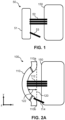
    • Fig. 1 schematically illustrates a cross-section of a cleaning module comprising two different groups of cleaning elements and a flat support surface;
    • Fig. 2A schematically illustrates a cross-section of a cleaning module for an oral cleaning device according to a proposed embodiment;
    • Fig. 2B is a simple illustration of an example target interaction profile of the cleaning module of Fig. 2A;
    • Fig. 3 is a simple illustration for explaining target compression percentages and target compression values;
    • Fig. 4A schematically illustrates a cross-section of a cleaning module for an oral cleaning device according to a proposed embodiment;
    • Fig. 4B is a simple illustration of an example target interaction profile of the cleaning module of Fig. 4A;
    • Figs. 5A-E schematically illustrate example shapes of support surfaces according to proposed embodiments;
    • Fig. 6 schematically illustrates a simplified toothbrush device comprising a cleaning module according to a proposed embodiment;
    • Fig. 7 schematically illustrates an example brushing mouthpiece device; and
    • Fig. 8 schematically illustrates an example layout of cleaning modules of two different shapes within a brushing mouthpiece device according to proposed embodiments.
    DETAILED DESCRIPTION OF THE EMBODIMENTS
  • The invention will be described with reference to the Figures.
  • It should be understood that the detailed description and specific examples, while indicating exemplary embodiments of the apparatus, systems and methods, are intended for purposes of illustration only and are not intended to limit the scope of the invention. These and other features, aspects, and advantages of the apparatus, systems and methods of the present invention will become better understood from the following description, appended claims, and accompanying drawings. It should be understood that the Figures are merely schematic and are not drawn to scale. It should also be understood that the same reference numerals are used throughout the Figures to indicate the same or similar parts.
  • Variations to the disclosed embodiments can be understood and effected by those skilled in the art in practicing the claimed invention, from a study of the drawings, the disclosure and the appended claims. In the claims, the word "comprising" does not exclude other elements or steps, and the indefinite article "a" or "an" does not exclude a plurality.
  • Implementations in accordance with the present disclosure relate to various techniques, methods, schemes and/or solutions pertaining to cleaning module for an oral cleaning device. According to proposed concepts, a number of possible solutions may be implemented separately or jointly. That is, although these possible solutions may be described below separately, two or more of these possible solutions may be implemented in one combination or another.
  • Embodiments of the invention aim to provide a cleaning module for an oral cleaning device. Proposed concepts thus aim to provide a cleaning module for an oral cleaning device which includes a non-flat support surface and at least two different groups of cleaning elements, wherein the groups are different by virtue of defining at least one different physical parameter compared to one another.
  • In other words, it is proposed that by having two different groups of cleaning elements, i.e. two groups of cleaning elements that differ in at least one physical parameter to one another, cleaning elements can be provided that are optimal for cleaning different dental areas, e.g. gumline and interdental. However, in order to counteract the fact that these different groups of cleaning elements may have different lengths, roll angles, etc., and so may interact with oral surfaces sub-optimally if extending from a flat support surface (e.g. short bristles not reaching the tooth because the long bristles are keeping the support surface at a certain distance from the tooth), a non-flat support surface can be provided such that, for example, short bristles may extend from a 'higher' portion of the support surface than longer bristles.
  • Referring now to Fig. 1, there is depicted a schematic illustration of a cross-section of a cleaning module 50 comprising two different groups of cleaning elements, 52 and 53 respectively, and a flat support surface 51. A cleaning module can also be understood, for example, as a cleaning section or a cleaning unit.
  • As can be seen, when the support surface 51 is flat, if the groups of cleaning elements, 52 and 53, define physical parameters respectively that differ too greatly from one another (in this case, length and angle of extension) then during use, one group of cleaning elements 53 may be restricted from interacting with an oral surface 150, such as a tooth. This therefore results in sub-optimal cleaning of a subject's oral surfaces. This is true even when the cleaning elements are not bristles or tufts of bristles, etc., but projections for fluid jets (e.g., air-jets, waterjets, air- and water-jets). For instance, waterjets work optimally at a certain distance from a subject's teeth / gums. This is also true even when the cleaning elements are electrodes or antenna for cleaning oral surfaces with electromagnetic fields - they too work optimally at a certain distance from a subject's teeth / gums.
  • An oral surface can be understood as a dental (tooth) surface or gum surface.
  • Referring now to Fig. 2A, there is depicted a schematic illustration of a cross-section of a cleaning module 100 for an oral cleaning device according to a proposed embodiment.
  • The cleaning module 100 comprises a support surface 110 that is non-flat with respect to a reference plane 120 which connects one end 110a of the cleaning module to another opposite end 110b of the cleaning module. The reference plane 120 can be understood as the axis shown in the figure (extending in the y-direction) also extending in z-direction (i.e. into the page) from one end of the support surface 110 (i.e. an end in the z-direction) to its opposite end. In other words, the reference plane 120 can be understood as representing the tooth-facing surface of an imaginary flat support surface. The reference plane 120 can also be understood as a plane in which opposite ends, 110a and 110b, of the support surface 110 are positioned, as well as opposite ends in the z-direction. In other terms, the reference plane 120 can be understood as passing through opposite ends, 110a and 110b, of the support surface 110, as well as the opposite ends in the z-direction. In yet other terms, the reference plane 120 can be understood as a plane in which, for example, at least three corners of the support surface 110 are positioned. The support surface 110 being non-flat with respect to the reference plane 120 can also be understood as the support surface 110 being non-parallel with the reference plane 120. Non-flat can be understood as any surface that cannot be completely defined in a two-dimensional space (a plane), but only in three-dimensional space.
  • Alternatively, the reference plane 120 could be understood as the median plane of the support surface 110, e.g., a plane tangential to the centre of the support surface 110. In this alternative case, the reference plane 120 can be understood as plane in which, for example, at least three non-colinear points of the support surface 110 are positioned.
  • The support surface 110 is configured such that the orthogonal distance of the support surface from the reference plane 120 varies along the reference plane. For example, the orthogonal distance 122 of one portion of the support surface 110 from the reference plane 120 is indicated. This value therefore changes, continuously or discontinuously, at different points on the reference plane 120. For instance, considering merely the y-direction, as one moves from the bottom of the reference plane 120 to the top, the orthogonal distance of the support surface 110 from the reference plane increases from zero to a maximum and then back to zero again. In some embodiments, the support surface 110 can be substantially inflexible, i.e., the shape of the support surface can be substantially unchangeable.
  • In some embodiments, the curve of the support surface 110 may be configured such that, in use, the curve goes from the bottom of a tooth 150 to the top of the tooth. Alternatively, or in addition, the curve of the support surface 110 may be configured such that, in use, the curve goes across the width of a tooth 150. Having the support surface 110 non-flat in either or both of these dimensions is beneficial for facilitating a desired target interaction profile, such as a substantially uniform interaction profile. In some embodiments, the cross-module of the cleaning module 100 shown in Fig. 2A may thus be substantially the same as the cleaning module's 100 cross-section in the z-direction, such that the support surface 110 forms a two-dimensional concave shape with respect to the reference plane 120. A two-dimensional concave shape has been found to be beneficial for integrating different groups of cleaning elements suited for different cleaning purposes, as well as being relatively efficient to manufacture. Similarly, the support surface 110 may be convex in two dimensions with respect to the reference plane 120 (i.e., the orthogonal distance of the support surface from the reference plane is inverted to that seen in Fig. 2A). This has also been found to be a beneficial shape for integrating different groups of cleaning elements suited for different cleaning purposes, as well as being relatively efficient to manufacture.
  • In this embodiment, a substantial portion of the support surface 110 has an orthogonal distance from the reference plane 120 of at least 2mm. This is not an essential component of the invention, however. In other embodiments, at least one portion of the support surface may have an orthogonal distance from the reference plane of at least 1mm. In this way, a minimum deviation in the support surface's 110 shape from a flat support surface is provided such that groups of cleaning elements that substantially vary from one another in at least one physical parameter can be supported to facilitate, for example, a substantially uniform target interaction profile. In other words, this feature ensures that the support surface 110 is not merely non-flat in any trivial way, but instead substantially non-flat.
  • The cleaning module 100 also comprises two groups of cleaning elements, 112 and 114, extending from the support surface 110. The groups of cleaning elements, 112 and 114, define a different physical parameter compared to one another. In other words, the two groups of cleaning elements, 112 and 114, are each unique in at least one physical parameter such as length, angle, stiffness, size of cleaning element, etc. A physical parameter can be understood as a physical property of a group of cleaning elements, such as the size of the group or the number of cleaning elements in the group, and/or a physical property of the cleaning elements themselves within the group, such as their height, roll angle, stiffness, comprising material, etc. In some embodiments, all the groups of cleaning elements may extend in a direction non-parallel to the reference plane.
  • In some embodiments, a physical parameter may comprise at least one of: spatial layout; height profile; stiffness profile; angular profile; size of cleaning elements; size of group; number of cleaning elements within a group; and comprising material of the cleaning elements. These are all parameters which can be varied for groups of cleaning elements, and different combinations of physical parameters may be optimal for different cleaning functions. An angular profile can be understood as the roll angle of the cleaning elements within the group. A stiffness profile may be understood as the stiffness per unit length value of the cleaning elements. The size of the cleaning elements or groups can be understood as their diameter, circumference (circular or rectangular, etc.), or perimeter length. In other words, the size can be understood as the spatial footprint on the support surface. The height profile of the groups of cleaning elements can be understood as the cleaning elements' length(s). For example, all the cleaning elements in a group may have the same length or they may have lengths that vary from one another according to a (height) profile for the group.
  • A cleaning element may comprise at least one of: a bristle; a tuft of bristles; a flexible elastomeric rod; a fibre; a group of fibres; and an elongate projection that has an orifice for a fluid-jet. These elements have been found to be beneficial in cleaning oral surfaces. A bristle is a single filament, typically nylon, which is used to clean oral surfaces. Thus, a tuft of bristles is a bundle of closely-packed filaments where one proximal end of each bristle is attached to the support surface 110 (either independently or fused-together), and the other end of each bristle is free and used for cleaning of an oral surface 150 (through brushing the oral surface with the bristle(s)).
  • In this embodiment, the groups of cleaning elements comprise one that is angled 114 and one that is non-angled 112. The angled group of cleaning elements 114 comprises cleaning elements that extend in a direction non-orthogonal to the reference plane 120. In this way, when the cleaning module 100 is placed parallel to an oral surface 150 (i.e. when the reference plane 120 is parallel to the oral surface, or a tangent of the oral surface), such as is the case here, at least some cleaning elements 114 will be angled with respect to the oral surface, and therefore can be more optimal for some cleaning purposes, e.g., gumline cleaning.
  • In other words, an angled group of cleaning elements is a group of cleaning elements that is attached to the support surface 110 at an angle that is not perpendicular to the reference plane 120. That is, the cleaning elements of an angled group form/define an angle with respect to the reference plane 120 that is less than 90° and greater than 0°. An angled group of cleaning elements may therefore be thought of as comprising cleaning elements that are tilted, slanted or angled with respect to the support surface.
  • The non-angled group of cleaning elements 112 comprises cleaning elements that extend in a direction orthogonal to the reference plane 120, i.e. in the x-direction. In this way, when the cleaning module 100 is placed parallel to the oral surface 150 (i.e., when the reference plane 120 is parallel to the oral surface 150), such as is the case here, at least some cleaning elements 112 will not be angled with respect to the oral surface (i.e., will be straight), and therefore can be more optimal for some cleaning purposes, e.g., interdental cleaning.
  • Referring now to Fig. 2B there is depicted a single illustration of an example target interaction profile 200 of the cleaning module 100 of Fig. 2A. The x-axis 210 represents positions along the support surface 110 in the y-direction of Fig. 2A. The y-axis 220 represents a target compression value of the groups of cleaning elements, 112 and 114, in mm. A target interaction profile is thus provided by the drawn line 230.
  • The groups of cleaning elements, 112 and 114, in Fig. 2A, can thus be understood as defining, in use, a target interaction profile 230 describing a variation of an interaction parameter (in this case, a target compression value) of the groups of cleaning elements with respect to the oral surface 150. It should be noted, however, that consideration of a target interaction profile is not essential to the invention.
  • It should also be noted that, in reality, the oral surface 150 is rarely homogenous and varies from tooth-to-tooth, gum-to-gum, and person-to-person. When considering the target interaction profile then, the oral surface 150 can be understood as the outermost plane tangential to the oral surface in question. In other words, when defining the target interaction profile 230 when the oral surface 150 is not perfectly flat, a tangential plane of the section of the oral surface which is closest to the support surface 110 can be used.
  • When the cleaning module 100 is being used, the individual cleaning elements will each have an interaction parameter with respect to the oral surface 150 (e.g., how compressed they are against the oral surface) and together, the interaction parameters of the groups of cleaning elements, 112 and 114, respectively may be taken as an interaction profile. The target interaction profile can then be understood as the expected interaction profile of the cleaning module 100 when in use, i.e., how each cleaning element is expected to interact with an oral surface 150 in use. The shape of the support surface 110 can then be configured in order to facilitate, in use, a target interaction profile. In other words, the shape of the support surface 110 can be configured to, in use, facilitate a target interaction parameter of each group of cleaning elements, 112 and 114, with respect to an oral surface 150. Alternatively, and equally, it can be considered that the physical parameters of the groups of cleaning elements can be configured in order to facilitate, in use, a target interaction profile for a given support surface. For instance, it may be desired that one group of cleaning elements have a target compression percentage, in use, of 40% and another of 50%; this can then be understood as the target interaction profile which the groups of cleaning elements define.
  • It should be noted that in use can be understood as in normal use, i.e., with the reference plane 120 of the cleaning module 100 parallel to an oral surface to be cleaned. In other words, whenever a feature is defined with respect to `in use', the feature must be considered with the reference plane 120 parallel to a tangent of the closest portion of an oral surface to be cleaned.
  • The target compression value of the groups of cleaning elements, 112 and 114, represented by axis 220 can be understood as, in use, the absolute length of the cleaning elements that will be compressed/bent by the oral surface 150. In other words, the target compression value can be understood as the absolute length of the portion of the cleaning elements respectively (within a group) that is, in use, superfluous to the distance from a proximal end of the cleaning element (where it meets the support surface 110) to a target oral surface 150. This concept is explained in more detail in Fig. 3.
  • Moving from the bottom of the reference plane 120 in Fig. 2A upwards, the first group of cleaning elements 114 has a target compression value of 1mm and the second group of cleaning elements 112 has a target compression value of 4mm. This therefore comprises a simple target interaction profile and is accordingly represented by the line 230, which is simply a line connecting the two data points. In other embodiments, in which more than two groups of cleaning elements are present, the line 230 (and therefore the target interaction profile) may accordingly be more complex.
  • In other embodiments, an interaction parameter may comprise at least one of a target compression value; and a percentage of cleaning elements engaging with an oral surface. The cleaning module can therefore be configured to facilitate, for example, a minimum percentage of cleaning elements within a group that will engage with an oral surface, thus facilitating more comprehensive oral cleaning.
  • For example, the variation of surface depth of the support surface 110 can be configured to be a function of the difference in length and roll angle (and/or any other physical parameter) between the different groups of cleaning elements and the target interaction profile. The shape of the support surface (and/or the physical parameters of the groups of cleaning elements) can also be configured according to a target tooth (i.e., the tooth which it will be cleaning, in use), for example, to accommodate for variations of tooth geometry such as size and shape.
  • Referring now to Fig. 3, there is depicted a simple illustration for explaining target compression percentages and target compression values. Various different groups of cleaning elements, 31, 32, 33, and 34, extending from a non-flat support surface (not-shown) can be seen interacting with an oral surface 150. Looking to group 31, a target compression percentage can be understood, in use (as is the case here) as the desired percentage of the total length 40 of the cleaning elements within the group that will be compressed/bent by the oral surface 150. In other words, a compression percentage can be understood as the percentage of the cleaning element length 40 that is, in use, superfluous (the length of the superfluous portion is given by the arrows 45) to the distance from a proximal end of the cleaning element to a target oral surface, i.e., length 40 minus length 45. In other words, a compression percentage can be understood as the percentage of the cleaning element length 40 that is, in use, overlapping with an outermost plane tangential to a target oral surface. In other words, to obtain the compression percentage of a group of cleaning elements, take the length of superfluous portion 45, divide it by the total length 40 of the cleaning elements, and multiply by one hundred. An alternative definition can be given by the following equation: CP = 100 CL D CL
    Figure imgb0001
  • In equation 1, CP stands for compression percentage, CL stands for cleaning element length (i.e., length 40), and D stands for the distance from a proximal end of the cleaning element to a target oral surface 150 (i.e., length 40 minus length 45). In some embodiments, D may be understood as the distance from a proximal end of the cleaning element to an outermost plane tangential to a target tooth.
  • All the groups of cleaning elements, 31, 32, 33, and 34, therefore have different target compression values, which is the absolute length of their superfluous portions, but the same target compression percentage. That is, in Fig. 3, each group of cleaning elements, 31, 32, 33, and 34 has a target compression percentage of around 30%. That is, 30% of their total length (e.g., length 40) will be compressed by an oral surface 150, in use; or, in other words, 30% of their total length is superfluous to the distance, in use, from a proximal end of the cleaning elements to the target oral surface.
  • Referring now to Fig. 4A, there is schematically illustrated a cross-section of a cleaning module 400 for an oral cleaning device according to a proposed embodiment. The cleaning module 400 is substantially similar to that described in relation to Fig. 2A, however, in this embodiment, there is provided a third group of cleaning elements 416. Further, both groups 414 and 416, as well as having different height and angular profiles to group 112, are also made of a stiffer material.
  • In this embodiment, the physical parameters (in this case, comprising height profile, angular profile, stiffness profile, size of cleaning elements, and number of cleaning elements within a group) of each group of cleaning elements, 112, 414, and 416, are configured based on the location of each group on the support surface 110 and a target interaction profile. In other words, for a target interaction profile, the physical parameter(s) of each group of cleaning elements are configured respectively to facilitate this profile in use.
  • More specifically, in this embodiment, the target interaction profile comprises a substantially uniform target interaction profile, wherein the groups of cleaning elements, 112, 414 and 416, have a substantially identical interaction parameter with respect to the oral surface 150. This facilitates the cleaning elements having, for example, substantially the same target compression percentage (in this case, 40%, as can be seen in Fig. 4B) - and thus, in use, each cleaning element should compress against the oral surface 150 in a substantially similar way. For example, it has been found that regardless of length, bristles typically have the same compression percentage that is optimal for cleaning. The target interaction profile can thus be configured to reflect this.
  • In other words, the cleaning module 400 facilitates improved cleaning at both gumline and interdental areas with cleaning elements extending from the same cleaning module, compared to a cleaning module with a flat support surface. Essentially, the proposed solution is to combine different cleaning element configurations for each of the critical cleaning zones in one cleaning module and to design the support surface and cleaning elements to enable substantially uniform and optimal compression (clamping) for all the groups of cleaning elements. Cleaning element layouts can be optimized for various tooth geometries or locations (molar, premolar, buccal, lingual, upper or lower jaw, etc.).
  • Looking to Fig. 4B, there is depicted a simple illustration of an example target interaction profile of the cleaning module 400 of Fig. 4A. It can therefore be seen that in the embodiment of cleaning module 400, the substantially identical interaction parameter with respect to the oral surface 150 comprises a target compression percentage for each group, in use, of 40%. That is, the target interaction profile represented by line 430 shows a uniform target compression percentage of the groups of cleaning elements, 112, 414, and 416, across the support surface. Similarly to Fig. 2B, the x-axis 410 represents positions along the support surface 110 in the y-direction of Fig. 4A. The y-axis 420 represents a target compression percentage of the groups of cleaning elements, 112, 414 and 416. A target interaction profile is thus provided by the drawn line 430, wherein the target interaction profile comprises a substantially uniform target interaction profile. For example, the target interaction profile may not be perfectly uniform due to curved tooth anatomy, and/or the target interaction profile may deviate slightly from perfectly uniform to account for the curve of teeth.
  • In other embodiments, the substantially identical interaction parameter with respect to the oral surface 150 may comprise a target compression percentage for each group, in use, between 20% and 60%. This has been found to be a beneficial range of compression for groups of cleaning elements, especially bristles. More specifically, the range of 30% to 50% has been found to be beneficial, and even more specifically, 40% has been found to be beneficial.
  • The graph 450 only shows the variation of the target interaction parameter in one direction (the y-direction), but the concept may equally be extended to two directions, e.g., uniform in the z-direction too.
  • In an example embodiment, the cleaning module of an oral device (e.g., a brush head or mouthpiece) consists of a support surface with a non-flat and unchangeable cross-section profile shape and with groups of cleaning elements (e.g. tufts) with different roll angles. For example, some groups can be straight for interproximal and frontal tooth cleaning, and other groups can be angled for cleaning gumline and occlusal areas. Essentially, the local curvature of the support surface at each tuft can be configured based on the angle and length of the tuft to therefore facilitate, for example, a substantially uniform compression profile. A similar compression percentage can therefore be applied, in use, to all tufts. For example, the shape of the support surface can be configured such that the distance from the support surface from which the tufts extend to the bristle tips is consistent, therefore facilitating uniform clamping for all tuft configurations of the cleaning module. For example, different tuft configurations may be provided for interdental and gumline cleaning respectively. For instance, the tuft configuration for interdental cleaning has bristle lengths of 10mm and a tuft roll angle of 90 degrees (i.e. straight). For instance, the tuft configuration for gumline cleaning has a bristle length of 4mm and a tuft roll angle of 45 degrees (therefore resulting in an orthogonal height of the gumline tufts of 2.8mm). To facilitate a target substantially uniform compression percentage profile of 40%, the support surface should therefore be configured to, in use, provide the interdental tufts at a distance of 6mm from the target tooth and the gumline tufts at a distance of 1.7mm. The support surface would therefore be configured such that the surface depth difference between the portions of the support surface from which the different tufts emerge would be 4.3mm.
  • Referring now to Figs. 5A-E, there are depicted schematic illustrations of example shapes of support surfaces according to proposed embodiments. All the depicted support surfaces in Figs. 5A-E can facilitate the provision of a substantially uniform target interaction profile, if provided with the necessary groups of cleaning elements, of which examples have been provided. It should be noted that the exact shapes of the support surfaces and the configurations of the groups of cleaning elements may be adjusted from what is shown. Figs. 5A-E are only provided as example shapes and configurations of groups of cleaning elements and should not be taken as limiting. It should be noted that throughout Figs. 5A-E, the direction of the cleaning elements and support surfaces is merely exemplary and in other embodiments, can be orientated in any other suitable direction (for example, to clean different sides or the crowns of teeth).
  • For example, Fig. 5A depicts a cross-section of a curved support surface 510, more specifically of a concave curved surface, from which two groups of cleaning elements extend, 512 and 514.
  • Fig. 5B depicts a cross-section of a curved support surface 510 comprising a curved convex surface. More specifically, the surface is convex to such an extent that the surface becomes semi-circular also. From the support surface 520, three groups of cleaning elements extend, 522, 524, and 526.
  • Fig. 5C depicts a cross-section of a stepped support surface 530, wherein the orthogonal distance of the support surface to the reference plane instantly jumps from one value to another. Two groups of cleaning elements, 532 and 534, can be seen to extend from the support surface 530.
  • Fig. 5D depicts a cross-section of a support surface 540 comprising an angled linear surface, wherein the support surface is comprised of straight lines which are non-parallel to the reference plane. Specifically, the support surface 540 in this case is a zig-zag linear surface comprising alternating angled linear sections of equal length. Three groups of cleaning elements, 542, 544 and 546, can be seen extending from the support surface 540.
  • Fig. 5E depicts a cross-section of a sinusoidal support surface 550. Three groups of cleaning elements, 553, 554 and 556, can be seen extending from the support surface 550.
  • Referring now to Fig. 6, there is depicted a schematic illustration of a simplified toothbrush device 600 comprising a cleaning module 400 according to a proposed embodiment. More specifically, the toothbrush device 600 comprises the cleaning module 400 described in relation to Fig. 4A. In other embodiments, however, the toothbrush device 600 can comprise a cleaning module of any herein disclosed embodiment.
  • The toothbrush device 600 comprises a handle 605 which connects to the support surface 110 (either directly or indirectly). The toothbrush may be manual or powered. From the support surface, the three previously described groups of cleaning elements, 414, 112 and 416, extend. A toothbrush device 600 capable of facilitating a substantially uniform target interaction profile is therefore provided.
  • Referring now to Fig. 7, there is depicted a schematic illustration of an example brushing mouthpiece device 8. The device 8 comprises a mouthpiece portion 12 for at least partial receipt in the mouth during use. A body of the mouthpiece portion defines an arcuate contour 30 shaped for approximately following a contour of at least a portion of a user's dental arch. The mouthpiece portion defines a tooth-receiving channel 16, the channel having a shape following said arcuate contour 30, to permit receipt of a row of teeth into the channel. Other mouthpiece devices may comprise two tooth-receiving channels, one for the lower jaw and one for the upper jaw. In other mouthpiece devices, there may be provided even more than two tooth-receiving channels if they are not contiguous along the jaw, i.e., if there are provided multiple distinct tooth-receiving channels for a single jaw.
  • In the context of such a such a device, at least one cleaning module could form part or whole of the mouthpiece portion 12 of the device (which does not necessarily have to be a full-mouth U shape, as is the case here, but instead can be a half-mouth J shape), thus facilitating the extension of cleaning elements 20 from the sides of the tooth-receiving channel, 16a and 16b, towards oral surfaces. In other words, the shape of the mouthpiece portion 12 is not restricted to a C- or U-shape, but can be a shape that enables brushing a segment of the jaw arch simultaneously (instead of only 1-2 teeth as is the case with standard powered or manual toothbrushes).
  • For example, the groups of cleaning elements 20 may extend into the channel 16 for engagement with oral (tooth and/or gum) surfaces during use. The mouthpiece device may further comprise a handle portion 52 for a subject to hold onto during use. In some embodiments, the handle portion 52 may comprise an actuation mechanism for driving periodic motion of the cleaning modules (and therefore cleaning elements) within the channel 16.
  • Referring now to Fig. 8, there is depicted a schematic illustration of an example layout of cleaning modules of two different shapes, 801 and 802 respectively, within a brushing mouthpiece device 8 according to proposed embodiments. In Fig. 8, it can be seen that the one of the walls 16b of the tooth-receiving channel 16 comprises alternating cleaning modules of two different shapes (A and B), 801 and 802. The axis 30 represents the arcuate contour 30 of Fig. 7, though warped to transform it, and the channel 16, into a straight line for ease of representation. In this embodiment, the other wall 16a of the channel comprises the same alternating shapes of cleaning modules, 801 and 802. In other embodiments, the two walls, 16a and 16b, may comprise different shapes of cleaning modules to one another. For instance, the two walls may comprise different shapes of cleaning modules configured for cleaning the back and front of a tooth respectively.
  • In this way, for example, alternating shapes of support surface, 801 and 802, may be provided, that when moved back and forth along the mesial-distal direction, may provide a tooth with cleaning from multiple groups of cleaning elements positioned in different ways. This may thus provide more complete cleaning. For example, one shape of cleaning module may be configured for gumline cleaning and the other for interdental cleaning.
  • In other embodiments, cleaning modules of three, four, five, six, seven, or eight different shapes may be provided, such that different teeth may be provided with different shaped support surfaces configured specifically to clean those teeth. For example, to facilitate this, the total width of a cleaning module can be less than one target tooth width. For example, for full (U-shaped) or partial (J-shaped) mouthpieces, the support surface curvature may vary from tooth to tooth to accommodate for teeth shape and size variations. In addition, in some embodiments, flexibility and means of varying compression percentage during a brushing session (e.g., via motors to alter distance of the cleaning modules to the target tooth), optimized for in-mouth location, can be enabled.
  • In this embodiment, the first shape 801 may comprise a concave curved surface and the second shape 802 may comprise a convex curved surface. This has been found to be a beneficial combination of support surface shapes.

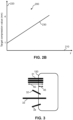
Claims (15)

  1. A cleaning module (100) for an oral cleaning device, comprising:
    a support surface (110) that is non-flat with respect to a reference plane (120) which connects one end (110a) of the cleaning module to another opposite end (110b) of the cleaning module, wherein the orthogonal distance of the support surface from the reference plane varies along the reference plane; and
    at least two groups of cleaning elements (112, 114) extending from the support surface, wherein the groups of cleaning elements define a different physical parameter compared to one another.
  2. The cleaning module of claim 1, wherein the groups of cleaning elements (112, 114) define, in use, a target interaction profile describing a variation of an interaction parameter of the groups of cleaning elements with respect to an oral surface (150).
  3. The cleaning module of claim 2, wherein the physical parameter of each group of cleaning elements (112, 114) is configured based on the location of each group on the support surface (110) and the target interaction profile.
  4. The cleaning module of claim 2 or 3, wherein the target interaction profile comprises a substantially uniform target interaction profile, wherein the groups of cleaning elements (112, 114) have a substantially identical interaction parameter with respect to the oral surface (150).
  5. The cleaning module of claim 4, wherein the substantially identical interaction parameter with respect to the oral surface (150) comprises a target compression percentage for each group, in use, between 20% and 60%.
  6. The cleaning module of any of claims 2 to 5, wherein an interaction parameter comprises at least one of: a target compression percentage; a target compression value; and a percentage of cleaning elements engaging with a oral surface (150).
  7. The cleaning module of any prior claim, wherein a physical parameter comprises at least one of: spatial layout; height profile; stiffness profile; angular profile; size of cleaning elements; size of group; number of cleaning elements within a group; and comprising material of the cleaning elements.
  8. The cleaning module of any prior claim, wherein at least one portion of the support surface (110) has an orthogonal distance from the reference plane (120) of at least 1mm, and preferably, at least 2mm.
  9. The cleaning module of any prior claim, wherein the support surface (110) comprises at least one of: a curved surface; a concave curved surface; a convex curved surface; a stepped surface; an angled linear surface; a zig-zag linear surface; a sinusoidal surface; and a semi-circular surface.
  10. The cleaning module of any prior claim wherein at least one group of cleaning elements comprises an angled group (114) of cleaning elements that extends in a direction not-orthogonal to the reference plane (120).
  11. The cleaning module of any prior claim, wherein the support surface (110) is concave in two dimensions with respect to the reference plane.
  12. The cleaning module of any prior claim, wherein the support surface (110) is convex in two dimensions with respect to the reference plane.
  13. A toothbrush device (600) comprising the cleaning module of any prior claim.
  14. A brushing mouthpiece device (8) comprising at least one cleaning module of any of claims 1 to 12.
  15. The brushing mouthpiece device of claim 14, wherein the brushing mouthpiece device comprises a cleaning module comprising a non-flat support surface of a first shape (801) and at least one further cleaning module comprising a non-flat support surface of a second shape (802), wherein the first shape and second shape are different compared to one another.
EP23198140.8A 2023-09-19 2023-09-19 Oral health care Withdrawn EP4527249A1 (en)

Priority Applications (1)

Application Number Priority Date Filing Date Title
EP23198140.8A EP4527249A1 (en) 2023-09-19 2023-09-19 Oral health care

Applications Claiming Priority (1)

Application Number Priority Date Filing Date Title
EP23198140.8A EP4527249A1 (en) 2023-09-19 2023-09-19 Oral health care

Publications (1)

Publication Number Publication Date
EP4527249A1 true EP4527249A1 (en) 2025-03-26

Family

ID=88097756

Family Applications (1)

Application Number Title Priority Date Filing Date
EP23198140.8A Withdrawn EP4527249A1 (en) 2023-09-19 2023-09-19 Oral health care

Country Status (1)

Country Link
EP (1) EP4527249A1 (en)

Citations (6)

* Cited by examiner, † Cited by third party
Publication number Priority date Publication date Assignee Title
WO1984002833A1 (en) * 1983-01-27 1984-08-02 Orvar Larsson Toothbrush
US4570282A (en) * 1982-09-27 1986-02-18 Kaufman Martin H Toothbrush
US5967152A (en) * 1997-12-31 1999-10-19 Amtec Products, Inc. Oral cleaning apparatus
KR20100055844A (en) * 2008-11-18 2010-05-27 권순만 Toothbrush
US20200345128A1 (en) * 2017-11-21 2020-11-05 M+C Schiffer Gmbh Toothbrush
GB2603960A (en) * 2021-02-23 2022-08-24 Omilana Kunle Tooth cleaning device

Patent Citations (6)

* Cited by examiner, † Cited by third party
Publication number Priority date Publication date Assignee Title
US4570282A (en) * 1982-09-27 1986-02-18 Kaufman Martin H Toothbrush
WO1984002833A1 (en) * 1983-01-27 1984-08-02 Orvar Larsson Toothbrush
US5967152A (en) * 1997-12-31 1999-10-19 Amtec Products, Inc. Oral cleaning apparatus
KR20100055844A (en) * 2008-11-18 2010-05-27 권순만 Toothbrush
US20200345128A1 (en) * 2017-11-21 2020-11-05 M+C Schiffer Gmbh Toothbrush
GB2603960A (en) * 2021-02-23 2022-08-24 Omilana Kunle Tooth cleaning device

Similar Documents

Publication Publication Date Title
KR100896361B1 (en) Toothbrushes
FI95098C (en) Toothbrush head
CN106028869B (en) Heads for Oral Care Tools
US9723912B2 (en) Toothbrush apparatus with an arcuate toothbrush head and bristle configuration
EP2710919A1 (en) Oral care implement
JPH08214947A (en) Brushes for caring for teeth and body
HUT68609A (en) Self-adjusting three-sided toothbrush and method of manufacturing thereof
HU216799B (en) Tooth-brush
EP2925188A1 (en) Orthodontic toothbrush
US8448283B2 (en) Toothbrush with dual rotary brushing system
EP4527249A1 (en) Oral health care
US9066580B2 (en) Toothbrush having bent bristles
US20130047364A1 (en) Flexible, ergonomic toothbrush with replaceable bristles
EP4551153B1 (en) Cleaning section for an oral cleaning device
EP4551154B1 (en) Cleaning section for an oral cleaning device
CN1449256A (en) Product with bristles
EP4302641A1 (en) Oral health care device
RU238192U1 (en) COMBINED TOOTHBRUSH
EP4461157A1 (en) Oral health care
TWI702940B (en) Tooth cleaning brush
WO2022203085A1 (en) Toothbrush
WO2015095086A1 (en) Toothbrush apparatus with an arcuate toothbrush head and bristle configuration

Legal Events

Date Code Title Description
PUAI Public reference made under article 153(3) epc to a published international application that has entered the european phase

Free format text: ORIGINAL CODE: 0009012

STAA Information on the status of an ep patent application or granted ep patent

Free format text: STATUS: THE APPLICATION HAS BEEN PUBLISHED

AK Designated contracting states

Kind code of ref document: A1

Designated state(s): AL AT BE BG CH CY CZ DE DK EE ES FI FR GB GR HR HU IE IS IT LI LT LU LV MC ME MK MT NL NO PL PT RO RS SE SI SK SM TR

STAA Information on the status of an ep patent application or granted ep patent

Free format text: STATUS: THE APPLICATION IS DEEMED TO BE WITHDRAWN

18D Application deemed to be withdrawn

Effective date: 20250927