EP4527233A1 - Upper and shoe - Google Patents
Upper and shoe Download PDFInfo
- Publication number
- EP4527233A1 EP4527233A1 EP22948027.2A EP22948027A EP4527233A1 EP 4527233 A1 EP4527233 A1 EP 4527233A1 EP 22948027 A EP22948027 A EP 22948027A EP 4527233 A1 EP4527233 A1 EP 4527233A1
- Authority
- EP
- European Patent Office
- Prior art keywords
- layer
- portions
- linear
- base member
- unfixed
- Prior art date
- Legal status (The legal status is an assumption and is not a legal conclusion. Google has not performed a legal analysis and makes no representation as to the accuracy of the status listed.)
- Pending
Links
Images







Classifications
-
- A—HUMAN NECESSITIES
- A43—FOOTWEAR
- A43B—CHARACTERISTIC FEATURES OF FOOTWEAR; PARTS OF FOOTWEAR
- A43B1/00—Footwear characterised by the material
- A43B1/02—Footwear characterised by the material made of fibres or fabrics made therefrom
- A43B1/04—Footwear characterised by the material made of fibres or fabrics made therefrom braided, knotted, knitted or crocheted
-
- A—HUMAN NECESSITIES
- A43—FOOTWEAR
- A43B—CHARACTERISTIC FEATURES OF FOOTWEAR; PARTS OF FOOTWEAR
- A43B1/00—Footwear characterised by the material
- A43B1/02—Footwear characterised by the material made of fibres or fabrics made therefrom
- A43B1/05—Footwear characterised by the material made of fibres or fabrics made therefrom woven
-
- A—HUMAN NECESSITIES
- A43—FOOTWEAR
- A43B—CHARACTERISTIC FEATURES OF FOOTWEAR; PARTS OF FOOTWEAR
- A43B23/00—Uppers; Boot legs; Stiffeners; Other single parts of footwear
- A43B23/02—Uppers; Boot legs
- A43B23/0245—Uppers; Boot legs characterised by the constructive form
- A43B23/025—Uppers; Boot legs characterised by the constructive form assembled by stitching
-
- A—HUMAN NECESSITIES
- A43—FOOTWEAR
- A43B—CHARACTERISTIC FEATURES OF FOOTWEAR; PARTS OF FOOTWEAR
- A43B23/00—Uppers; Boot legs; Stiffeners; Other single parts of footwear
- A43B23/02—Uppers; Boot legs
- A43B23/0245—Uppers; Boot legs characterised by the constructive form
- A43B23/0265—Uppers; Boot legs characterised by the constructive form having different properties in different directions
-
- A—HUMAN NECESSITIES
- A43—FOOTWEAR
- A43B—CHARACTERISTIC FEATURES OF FOOTWEAR; PARTS OF FOOTWEAR
- A43B23/00—Uppers; Boot legs; Stiffeners; Other single parts of footwear
- A43B23/24—Ornamental buckles; Other ornaments for shoes without fastening function
Definitions
- the present disclosure relates to an upper and a shoe including the upper.
- the upper includes a cloth-like base member.
- the base member normally includes one or more layers each including a front surface and a back surface.
- a conventional embroidery is formed by sewing yarns onto the base member after the base member is manufactured.
- a “yarn” fixed to the base member will be referred to as a "linear member”.
- the positions of the linear members in the base member are preferably selectable as desired.
- Patent Literature 1 JP 2020-525088 W
- the conventional embroideries however, in a case where the base member is formed with one layer, the linear members are disposed over the front surface, the back surface, and the inside of the layer of the base member without fail, and, in a case where the base member is formed with two or more layers, the linear members are disposed over the respective layers of the base member without fail. Therefore, the conventional embroideries have a problem in that the degree of freedom in selecting the positions of the linear members in the base member is low.
- the present disclosure has been made in view of the above, and aims to obtain an upper capable of increasing the degree of freedom in selecting the positions of linear members in the base member.
- an upper comprising: a cloth-like base member that includes one layer having a front surface and a back surface facing in an opposite direction from the front surface; and a plurality of linear members that are disposed side by side in the base member and are formed independently of each other, wherein each linear member of the plurality of linear members includes: a plurality of fixed portions that are fixed to the layer, and are disposed at a distance from each other; and a plurality of unfixed portions that are located between adjacent ones of the fixed portions, and are not fixed to the layer, each linear member of the plurality of linear members is folded back and forth in an in-plane direction of the layer, and a plurality of the unfixed portions continuous via the fixed portions is disposed to be exposed through at least one of the front surface or the back surface of the layer, or is disposed inside the layer.
- An upper according to the present disclosure has an effect of increasing the degree of freedom in selecting the positions of linear members in the base member.
- FIG. 1 is a developed view illustrating the upper 2 of a shoe 1 according to a first embodiment of the present disclosure.
- FIG. 1 only the shoe 1 for the left foot is illustrated. Since the shoe 1 for the left foot has a structure symmetrical with the shoe for the right foot, only the shoe 1 for the left foot is described in the present embodiment, and explanation of the shoe 1 for the right foot is not made herein.
- a direction in which a shoe center axis C, which is a perpendicular line extending through the center of the shoe 1 in a planar view of the shoe 1, extends will be referred to as the longitudinal direction
- a direction orthogonal to the longitudinal direction in a planar view of the shoe 1 will be referred to as the foot width direction.
- the direction from the heel toward the toe of the shoe 1 will be referred to as the fore direction
- the direction from the toe toward the heel of the shoe 1 will be referred to as the rear direction.
- the median side in the anatomical normal position of the foot will be referred to as the medial foot side
- the side opposite to the median side in the anatomical normal position of the foot will be referred to as the lateral foot side. That is, the side closer to the median line in the anatomical normal position will be referred to as the medial foot side, and the side farther from the median line in the anatomical normal position will be referred to as the lateral foot side.
- the vertical direction means the direction orthogonal to both the longitudinal direction and the foot width direction, unless otherwise specified.
- the upper 2 includes an upper fore foot position R1 covering the fore foot position of a foot of a wearer having a standard body shape, an upper middle foot position R2 covering the middle foot position of the foot of the wearer having a standard body shape, and an upper rear foot position R3 covering the rear foot position of the foot of the wearer having a standard body shape.
- the upper fore foot position R1, the upper middle foot position R2, and the upper rear foot position R3 are successively present in this order in the direction from the fore to the rear of the upper 2.
- the line that extends in the foot width direction and passes through a position corresponding to about 30% to 40% of the dimension of the upper 2 in the longitudinal direction of the upper 2 from the fore end is defined as a first boundary line S1
- the line that extends the foot width direction and passes through a position corresponding to about 73% to 83% of the dimension of the upper 2 in the longitudinal direction from the fore end of the upper 2 is defined as a second boundary line S2.
- the first boundary line S1 is a line that extends substantially along the MP joint of the wearer having a standard body shape.
- the second boundary line S2 is a line that extends substantially along the Chopart's joint of the wearer having a standard body shape.
- the upper fore foot position R1 is a portion located on the fore side of the first boundary line S1.
- the upper middle foot position R2 is a portion located between the first boundary line S1 and the second boundary line S2.
- the upper rear foot position R3 is a portion located on the rear side of the second boundary line S2.
- FIG. 2 is a perspective view illustrating the shoe 1 according to the first embodiment of the present disclosure.
- the shoe 1 is preferably a shoe for running, but may be a shoe for some other sport, a shoe for walking, a shoe for climbing, or the like.
- the shoe 1 includes the upper 2 and a sole 3.
- the upper 2 is located above the sole 3.
- the upper 2 includes a base member 20, a linear member placement region 21, a shoe tongue 23, and a shoelace 24.
- the base member 20 covers a portion on the instep side of the foot of the wearer.
- a foot insertion opening 20a and a throat portion 20b are disposed at an upper portion of the base member 20.
- the foot insertion opening 20a is an opening for allowing the foot of the wearer to enter the inside of the base member 20.
- the throat portion 20b is an opening that communicates with the foot insertion opening 20a and extends in the fore direction from the foot insertion opening 20a.
- a plurality of lace hole portions 20c separated from one another in the longitudinal direction is disposed on both side edges of the throat portion 20b in the foot width direction. In FIG. 2 , only the lace hole portions 20c disposed at the side edge on the lateral foot side of the throat portion 20b are illustrated.
- the lace hole portions 20c only needs to enable the shoelace 24 to pass therethrough.
- the lace hole portions 20c are through holes penetrating the base member 20 in the thickness direction of the base member 20, for example.
- FIGS. 1 and 2 to clarify the range of the linear member placement region 21, dot hatching is applied to the linear member placement region 21.
- the linear member placement region 21 plays a role of decorating the upper 2 and a role of partially changing the physical properties of the upper 2. Details of the base member 20 and the linear member placement region 21 will be described later.
- the shoe tongue 23 is a member for protecting the instep of the foot of the wearer.
- the shoe tongue 23 covers the throat portion 20b inside the base member 20.
- the shoe tongue 23 is secured to the base member 20 by stitching, welding, bonding, or a combination thereof.
- the base member 20 and the shoe tongue 23 are knitted fabrics in which yarns are rolled into a chain-like shape and chain-like portions are hooked to one another to form a cloth, woven fabrics in which warp yarns and weft yarns cross each other at a certain angle to form a cloth, or compositions in which three or more braid yarns cross one another and run obliquely to form a cloth, for example.
- the upper 2 including the shoe tongue 23 and the shoelace 24 is described as an example, but the upper 2 may have a monosock structure in which the portion corresponding to the shoe tongue 23 is integrated with the ankle portion of the base member 20.
- the means for bringing the base member 20 into close contact with the foot may be a hook-and-loop fastener, for example, instead of the shoelace 24.
- the lace hole portions 20c are not disposed in the base member 20.
- the sole 3 is located below the upper 2.
- the sole 3 covers the sole of the wearer.
- the sole 3 is secured to the base member 20 by stitching, welding, bonding, or a combination thereof.
- the sole 3 includes an outsole 30 and a midsole 31.
- the lower face of the outsole 30 serves as a ground contact face 30a to be in contact with the ground.
- the midsole 31 is located on the upper face of the outsole 30, and has cushioning properties. Note that the outsole 30 may be integrated with the midsole 31.
- the outsole 30 integrated with the midsole 31 is also referred to as the "unisole".
- the sole 3 includes an inner sole that covers the lower opening of the base member 20.
- the inner sole is secured to the upper face of the midsole 31 by adhesion or welding.
- the inner sole is secured to the lower edge of the base member 20 by stitching.
- the shoe 1 may include an insole. In a case where the shoe 1 includes an insole, the insole is placed on the sole 3 inside the upper 2. Note that the sole 3 may have a structure that excludes the inner sole.
- FIG. 3 is a cross-sectional view taken along the line III-III illustrated in FIG. 2 .
- FIG. 4 is a view when the upper 2 is viewed from an arrow X illustrated in FIG. 3 .
- the base member 20 includes the upper fore foot position R1, the upper middle foot position R2, and the upper rear foot position R3. As illustrated in FIG. 2 , the base member 20 is disposed over the entire region of the upper 2, except for the shoe tongue 23 and the shoelace 24. As illustrated in FIG. 3 , the base member 20 is a cloth-like member having one layer 20d.
- the layer 20d includes a front surface 20e, and a back surface 20f facing in the opposite direction from the front surface 20e.
- the front surface 20e is the surface facing the outside of the upper 2. In other words, the front surface 20e is the surface located on the opposite side from the foot of the wearer.
- the back surface 20f is the surface facing the inside of the upper 2. In other words, the back surface 20f is the surface located on the side of the foot of the wearer.
- the base member 20 is a knitted fabric in which a plurality of yarns 20g is knitted.
- the base member 20 includes a plurality of wales 20h extending in a first direction and a plurality of courses 20i extending in a second direction orthogonal to the first direction. One of the first direction and the second direction coincides with the longitudinal direction, and the other one of the first direction and the second direction coincides with the foot width direction.
- the linear member placement regions 21 are disposed in the upper fore foot position R1 and the upper middle foot position R2 of the base member 20. In the present embodiment, the linear member placement regions 21 are disposed at the positions indicated by dot hatching in FIG. 1 . The positions of the linear member placement regions 21 are not limited to the illustrated examples. As illustrated in FIG. 4 , the linear member placement regions 21 are the regions in which a plurality of linear members 22 are disposed. The plurality of linear members 22 is arranged side by side in the base member 20 and are disposed independently of one another. The plurality of linear members 22 is arranged in the in-plane direction of the base member 20. Each linear member of the plurality of linear members 22 is folded back and forth in the in-plane direction of the base member 20. The linear members 22 have a variation range of 3 mm or wider in the longitudinal direction or the foot width direction.
- the linear members 22 and the yarns 20g of the base member 20 are yarns obtained by bundling a plurality of fibers, linear resins, twisted yarns, or the like, for example.
- the materials of the linear members 22 and the yarns 20g of the base member 20 are polyester, polyurethane-based thermoplastic elastomer, polyurethane, nylon, spandex, Kevlar (registered trademark), ultra-high molecular weight polyethylene, single covered Yarn (SCY) or double covered Yarn (DCY) covered with polyurethane, or the like, for example.
- the material of some or all of the plurality of linear members 22 and the material of the yarns 20g of the base member 20 may be the same as each other, or be different from each other.
- the material of at least one linear member of the plurality of linear members 22 and the material of the yarns 20g of the base member 20 may be different from each other.
- the width of some or all of the plurality of linear members 22 and the width of the yarns 20g of the base member 20 may be the same as each other, or be different from each other.
- the width of at least one linear member of the plurality of linear members 22 and the width of the yarns 20g of the base member 20 may be different from each other.
- the melting point of the material of at least one linear member of the plurality of linear members 22 is preferably lower than the melting point of the material of the base member 20.
- some or all of the plurality of linear members 22 may be yarns having a lower melting point than that of the yarns 20g of the base member 20.
- some or all of the plurality of linear members 22 may be composite yarns containing fibers having different melting points.
- a core-in-sheath structure in which a core material (fiber) having a high melting point is covered with a low-melting-point material is preferably used for some or all of the plurality of linear members 22.
- the linear members 22 when the linear members 22 are subjected to a heat treatment at a temperature equal to or higher than the melting point of the low-melting-point material, the low-melting-point material is locally melted and solidified.
- the tensile rigidity of the upper 2 can be further enhanced.
- Each linear member of the plurality of linear members 22 includes a plurality of fixed portions 22a fixed to the layer 20d, and a plurality of unfixed portions 22b not fixed to the layer 20d.
- the fixed portions 22a are disposed apart from one another.
- the fixed portions 22a are portions that are passed through aperture portions 20j disposed in the base member 20 and are entangled with the yarns 20g.
- the aperture portions 20j are circular holes.
- the aperture portions 20j are disposed, being entangled with some of the adjacent loops of the base member 20.
- the unfixed portions 22b are disposed apart from one another.
- the unfixed portions 22b are located between the adjacent fixed portions 22a.
- the length L of the unfixed portions 22b in the first direction may be set as appropriate, but is preferably greater than 3 mm.
- Each unfixed portion of the plurality of unfixed portions 22b is disposed across one wale of the base member 20, and is disposed across two courses of the base member 20.
- the number of courses of the base member 20 crossed by the unfixed portions 22b is larger than the number of wales of the base member 20 crossed by the unfixed portions 22b.
- the plurality of linear members 22 is disposed to be exposed through the front surface 20e of the layer 20d, or is disposed to be exposed through the back surface 20f of the layer 20d.
- FIG. 3 illustrates a state in which two linear members 22 disposed separately are arranged in the length direction of the linear members 22.
- the one linear member 22 indicated by a dot-and-dash line will be referred to as the first linear member 22A
- the other linear member 22 indicated by a dashed line will be referred to as the second linear member 22B.
- the plurality of unfixed portions 22b continuous via the fixed portions 22a in the first linear member 22A is disposed to be exposed through the front surface 20e of the layer 20d.
- the unfixed portions 22b of the first linear member 22A are exposed through the front surface 20e of the base member 20 located on the opposite side from the foot of the wearer.
- the plurality of unfixed portions 22b continuous via the fixed portions 22a is disposed to be exposed through the back surface 20f of the layer 20d.
- the unfixed portions 22b of the second linear member 22B are exposed through the back surface 20f of the base member 20 located on the side of the foot of the wearer.
- the material of the first linear member 22A and the material of the second linear member 22B may be the same as each other, or may be different from each other.
- the width of the first linear member 22A and the width of the second linear member 22B may be the same as each other, or may be different from each other.
- the base member 20 and the linear member placement regions 21 can be formed in one step using a dedicated machine such as a warp knitting machine.
- FIG. 5 is a cross-sectional view illustrating the upper 110 of a shoe 100 according to a comparative example, and is a view illustrating a state in which embroideries are disposed on the upper 110 in which the layer 20d of the base member 20 is a single layer.
- the unfixed portions 22b of a linear member 22 are alternately exposed through the front surface 20e and the back surface 20f of the layer 20d.
- each linear member of the plurality of linear members 22 includes a plurality of fixed portions 22a that are fixed to the layer 20d and are disposed apart from each other, and a plurality of unfixed portions 22b that are located between the adjacent fixed portions 22a and are not fixed to the layer 20d.
- the plurality of unfixed portions 22b continuous via the fixed portions 22a is disposed to be exposed through the front surface 20e of the layer 20d, or is disposed to be exposed through the back surface 20f of the layer 20d.
- the plurality of unfixed portions 22b of one linear member 22 can be continuously exposed through the front surface 20e of the layer 20d, and the plurality of unfixed portions 22b of one linear member 22 can be continuously exposed through the back surface 20f of the layer 20d.
- the degree of freedom in selecting the positions of the linear members 22 in the base member 20 can be made higher than those with conventional embroideries.
- any design can be freely applied to the appearance of the upper 2. Further, in a case where the plurality of unfixed portions 22b continuous via the fixed portions 22a is disposed to be exposed through the front surface 20e of the layer 20d, and in a case where the linear members 22 having high abrasion strength are used, the abrasion strength and the tensile rigidity of the outer surface of the upper 2 can be enhanced while the feeling to be felt by the wearer touching the base member 20 with the foot is maintained as the feeling of touching the upper 2.
- the unfixed portions 22b continuous via the fixed portions 22a do not affect the design of the upper 2, or hardly affects the design of the upper 2.
- the design of the base member 20 is easily maintained as the design of the appearance of the upper 2.
- the abrasion strength and the tensile rigidity of the inner surfaces of the upper 2 can be enhanced.
- the feeling to be felt by the foot of the wearer touching the linear members 22 can be enhanced. That is, as the positions of the linear members 22 in the base member 20 can be selected as appropriate in the present embodiment, the physical properties of the upper 2 can be partially changed freely while the range of expression of the design of the upper 2 is widened.
- the plurality of unfixed portions 22b is continuously exposed through the front surface 20e of the layer 20d, like the first linear member 22A. Accordingly, irregularities do not appear on the back surface 20f of the layer 20d, and the upper 2 having a preferred feeling of foot contact can be provided without the use of any backing material.
- the formation of the base member 20 and the formation of the linear member placement regions 21 illustrated in FIG. 3 can be performed in one step in the present embodiment, the number of manufacturing steps, the amount of waste material, and the like of the upper 2 can be reduced, and thus, the cost and the environmental load can be reduced.
- each linear member 22 is necessary to dispose each linear member 22 across two or more of the courses and two or more of the wales constituting the base member 20.
- the maximum size of the courses and the wales is about 3 mm, and therefore, the variation range of the linear members 22 is preferably 3 mm or wider as in the present embodiment.
- a backing material and an adhesive are required.
- the first linear member 22A disposed to be exposed through the front surface 20e of the layer 20d, and the second linear member 22B disposed to be exposed through the back surface 20f of the layer 20d are disposed separately from each other.
- the size of the stitches is 3 mm at the maximum. Since the length L of the unfixed portions 22b illustrated in FIG. 4 exceeds 3 mm in the present embodiment, a design that cannot be expressed with a knitted fabric can be applied to the appearance of the upper 2.
- the thickness of at least one linear member of the plurality of linear members 22 illustrated in FIG. 4 and the thickness of the yarns 20g of the base member 20 are made different from each other, physical properties such as abrasion strength and tensile rigidity can be made different between the linear members 22 and the yarns 20g. Accordingly, the physical properties of the upper 2 at the portions where the linear members 22 are disposed, and the physical properties of the upper 2 at the portions where the linear members 22 are not disposed can be made different from each other.
- At least one unfixed portion of the plurality of unfixed portions 22b is disposed across two or more courses of the base member 20.
- a design that cannot be expressed with a knitted fabric can be applied to the appearance of the upper 2, and the tensile rigidity of the upper 2 in the course direction can be increased.
- the number of courses of the base member 20 crossed by the unfixed portions 22b is larger than the number of wales of the base member 20 crossed by the unfixed portions 22b.
- the base member 20 is formed with a material that is easy to stretch
- the linear members 22 are formed with a material that is difficult to stretch, for example, an upper 2 that is easy to stretch in the wale direction (first direction) but is difficult to stretch in the course direction (second direction) can be manufactured.
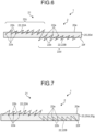
- FIG. 6 is a cross-sectional view illustrating the upper 2 of a shoe 1 according to a first modification of the first embodiment of the present disclosure, and is a view corresponding to a cross-sectional view taken along the line III-III illustrated in FIG. 2 .
- the linear member 22 is a single member having a first region 22c and a second region 22d.
- the first region 22c is a region in which a plurality of unfixed portions 22b continuous via fixed portions 22a is disposed to be exposed only through the front surface 20e of the layer 20d.
- the second region 22d is a region in which a plurality of unfixed portions 22b continuous via fixed portions 22a is disposed to be exposed only through the back surface 20f of the layer 20d.
- the linear member 22 is a single member having the first region 22c and the second region 22d in this modification, it is possible to reduce the processing cost and the environmental load, compared with those in a case where the portion corresponding to the first region 22c and the portion corresponding to the second region 22d are formed separately from each other. Since the linear member 22 is a single member having the first region 22c and the second region 22d in this modification, when the first region 22c is pulled, tension can be applied to the second region 22d, and fitting between the foot and the upper 2 can be enhanced. Note that it is only required that at least one linear member of the plurality of linear members 22 is a single member having the first region 22c and the second region 22d.
- the configuration of the first linear member 22A is the same as that of the first embodiment.
- the entire second linear member 22B is disposed inside the layer 20d.
- the second linear member 22B also includes a plurality of fixed portions 22a and a plurality of unfixed portions 22b.
- the fixed portions 22a are portions interwoven with yarns 20g inside the layer 20d.
- the unfixed portions 22b are portions not interwoven with the yarns 20g inside the layer 20d.
- the plurality of unfixed portions 22b continuous via the fixed portions 22a is disposed inside the layer 20d.
- the unfixed portions 22b of the second linear member 22B are not exposed through the front surface 20e and the back surface 20f of the base member 20.
- the linear members 22 can be disposed inside the layer 20d of the base member 20.
- the unfixed portions 22b are somewhat visible when the exterior of the upper 2 is viewed, but a design similar to the base member 20 is easily maintained as the design of the appearance of the upper 2. Also, in a case where the plurality of unfixed portions 22b continuous via the fixed portions 22a is disposed inside the layer 20d, it is possible to enhance the tensile rigidity of the upper 2 while maintaining the feeling to be felt by the wearer touching the base member 20 with the foot, as the feeling of touching the upper 2.
- the design of the base member 20 can be used as it is or some other design can be applied to the base member 20, and the physical properties of the base member 20 can be used as they are or some other physical properties can be imparted to the base member 20.
- a linear member 22 to be exposed through the front surface 20e of the layer 20d and a linear member 22 to be disposed inside the layer 20d may be integrally formed.
- the linear members 22 are formed as a single member having a first region and a second region.
- the first region is a region in which a plurality of unfixed portions 22b continuous via fixed portions 22a is disposed to be exposed only through the front surface 20e of the layer 20d.
- the second region is a region in which a plurality of unfixed portions 22b continuous via fixed portions 22a is disposed only inside the layer 20d.
- the linear members 22 can also be disposed on the front surface 20e of the layer 20d, inside the layer 20d, and on the back surface 20f of the layer 20d illustrated in FIG. 7 .
- the region is divided into a region in which the unfixed portions 22b can be clearly seen, a region in which the unfixed portions 22b can be somewhat seen, and a region in which the unfixed portions 22b cannot be seen. Accordingly, it is possible to express a design having a height difference not only in the in-plane direction of the upper 2 but also in the thickness direction of the upper 2. That is, a three-dimensional design including the thickness direction of the upper 2 and the in-plane direction of the upper 2 can be created.
- the layer 20d is a porous member such as a mesh
- the unfixed portions 22b disposed inside the layer 20d and on the back surface 20f of the layer 20d might be visible.
- the linear members 22 may be disposed on the front surface 20e of the layer 20d, inside the layer 20d, and on the back surface 20f of the layer 20d. With such arrangement, the visibility of the unfixed portions 22b changes depending on the positions of the unfixed portions 22b in the base member 20. Thus, the linear members 22 can be made to appear blurred, and a design having a height difference in the thickness direction of the upper 2 can be expressed.
- the layout of the unfixed portions 22b is not limited to the example illustrated in FIG. 4 , and may be changed as appropriate.
- at least one unfixed portion of the plurality of unfixed portions 22b may be disposed across two or more wales of the base member 20, or two or more courses of the base member 20.
- FIG. 8 is a view illustrating the upper 2 of a shoe 1 according to a third modification of the first embodiment of the present disclosure, and is a view corresponding to a view of the upper 2 seen from the arrow X illustrated in FIG. 3 .
- Each unfixed portion of a plurality of unfixed portions 22b is disposed across five wales of the base member 20, and is disposed across one course of the base member 20.
- the number of wales of the base member 20 crossed by the unfixed portions 22b is larger than the number of courses of the base member 20 crossed by the unfixed portions 22b.
- a design that cannot be expressed with a knitted fabric can be applied to the appearance of the upper 2.
- the base member 20 is formed with a material that is easy to stretch
- the linear members 22 are formed with a material that is difficult to stretch, for example, an upper 2 that is easy to stretch in the course direction (second direction) but is difficult to stretch in the wale direction (first direction) can be manufactured.
- an upper 2 that is easy to stretch in the course direction (second direction) but is difficult to stretch in the wale direction (first direction)
- the number of courses of the base member 20 crossed by the unfixed portions 22b and the number of wales of the base member 20 crossed by the unfixed portions 22b may be the same.
- the base member 20 is a knitted fabric in which a plurality of yarns 20g is knitted.
- a woven fabric in which a plurality of yarns 20g is woven, or a composition in which a plurality of yarns 20g is combined may be used, for example.
- FIG. 9 is a cross-sectional view illustrating the upper 2A of the shoe 1A according to the second embodiment of the present disclosure, and is a view corresponding to a cross-sectional view taken along the line III-III illustrated in FIG. 2 .
- FIG. 10 is a view illustrating the upper 2A of the shoe 1A according to the second embodiment of the present disclosure, and is a view corresponding to a view of the upper 2A seen from an arrow X illustrated in FIG. 9 .
- the shoe 1A according to the second embodiment differs from the shoe 1 according to the first embodiment in that the base member 20 has two or more layers 20d.
- the base member 20 is a cloth-like member having two or more layers 20d.
- the number of layers 20d of the base member 20 is three in the present embodiment, but may be changed as appropriate.
- the base member 20 includes a first layer 20k, a second layer 20m disposed at a distance from the first layer 20k, and a third layer 20n located between the first layer 20k and the second layer 20m.
- the first layer 20k is located on the outermost side in the base member 20. In other words, the first layer 20k is the layer 20d farthest from the foot of the wearer in the base member 20.
- the second layer 20m is located on the innermost side in the base member 20. In other words, the second layer 20m is the layer 20d located closest to the side of the foot of the wearer in the base member 20.
- the third layer 20n is located between the first layer 20k and the second layer 20m.
- the third layer 20n is a layer 20d that connects the first layer 20k and the second layer 20m, and prevents the first layer 20k and the second layer 20m from coming into contact with each other.
- the third layer 20n includes a portion connecting the first layer 20k and the second layer 20m.
- the third layer 20n includes a space formed between the first layer 20k and the second layer 20m.
- Each of the first layer 20k and the second layer 20m includes a front surface 20e, and a back surface 20f facing in the opposite direction from the front surface 20e.
- the front surface 20e of the first layer 20k is a surface facing the outside of the upper 2A in the first layer 20k. In other words, the front surface 20e of the first layer 20k is a surface located on the opposite side from the foot of the wearer in the first layer 20k.
- the back surface 20f of the first layer 20k is a surface facing the inside of the upper 2A in the first layer 20k. In other words, in the first layer 20k, the back surface 20f of the first layer 20k is a surface located on the side of the foot of the wearer.
- the front surface 20e of the second layer 20m is a surface facing the inside of the upper 2A in the second layer 20m. In other words, the front surface 20e of the second layer 20m is a surface located on the side of the foot of the wearer in the second layer 20m.
- the back surface 20f of the second layer 20m is a surface facing the outside of the upper 2A in the second layer 20m. In other words, the back surface 20f of the second layer 20m is a surface located on the opposite side from the foot of the wearer in the second layer 20m.
- the surface of each layer 20d exposed to the inside or the outside of the upper 2A is the front surface 20e, and the surface of each layer 20d exposed to neither of the inside and the outside of the upper 2A is the back surface 20f.
- the base member 20 is a knitted fabric in which a plurality of yarns 20g is knitted.
- the base member 20 includes a plurality of wales 20h extending in a first direction and a plurality of courses 20i extending in a second direction orthogonal to the first direction. One of the first direction and the second direction coincides with the longitudinal direction, and the other one of the first direction and the second direction coincides with the foot width direction.
- the linear member placement regions 21 are disposed in the upper fore foot position R1 and the upper middle foot position R2 of the base member 20.
- the linear member placement regions 21 are disposed at the positions indicated by dot hatching in FIG. 1 .
- the positions of the linear member placement regions 21 are not limited to the illustrated examples.
- the linear member placement regions 21 are the regions in which a plurality of linear members 22 is disposed.
- the plurality of linear members 22 is arranged side by side in the base member 20 and are disposed independently of one another.
- the plurality of linear members 22 is arranged in the in-plane direction of the base member 20.
- Each linear member of the plurality of linear members 22 is folded back and forth in the in-plane direction of the base member 20.
- the linear members 22 have a variation range of 3 mm or wider in the longitudinal direction or the foot width direction.
- the linear members 22 and the yarns 20g of the base member 20 are yarns obtained by bundling a plurality of fibers, linear resins, twisted yarns, or the like, for example.
- the materials of the linear members 22 and the yarns 20g of the base member 20 are polyester, polyurethane-based thermoplastic elastomer, polyurethane, nylon, spandex, Kevlar (registered trademark), ultra-high molecular weight polyethylene, single covered Yarn (SCY) or double covered Yarn (DCY) covered with polyurethane, or the like, for example.
- the material of some or all of the plurality of linear members 22 and the material of the yarns 20g of the base member 20 may be the same as each other, or be different from each other.
- the material of at least one linear member of the plurality of linear members 22 and the material of the yarns 20g of the base member 20 may be different from each other.
- the width of some or all of the plurality of linear members 22 and the width of the yarns 20g of the base member 20 may be the same as each other, or be different from each other.
- the width of at least one linear member of the plurality of linear members 22 and the width of the yarns 20g of the base member 20 may be different from each other.
- the melting point of the material of at least one linear member of the plurality of linear members 22 is preferably lower than the melting point of the material of the base member 20.
- some or all of the plurality of linear members 22 may be yarns having a lower melting point than that of the yarns 20g of the base member 20.
- some or all of the plurality of linear members 22 may be composite yarns containing fibers having different melting points.
- a core-in-sheath structure in which a core material (fiber) having a high melting point is covered with a low-melting-point material is preferably used for some or all of the plurality of linear members 22.
- the linear members 22 when the linear members 22 are subjected to a heat treatment at a temperature equal to or higher than the melting point of the low-melting-point material, the low-melting-point material is locally melted and solidified.
- the tensile rigidity of the upper 2 can be further enhanced.
- Each linear member of the plurality of linear members 22 includes a plurality of fixed portions 22a fixed to at least one layer 20d, and a plurality of unfixed portions 22b not fixed to any layer 20d.
- the fixed portions 22a are disposed apart from one another.
- the fixed portions 22a are portions that are passed through aperture portions 20j disposed in the base member 20 and are entangled with the yarns 20g.
- the aperture portions 20j are circular holes.
- the aperture portions 20j are disposed, being entangled with some of the adjacent loops of the base member 20.
- the unfixed portions 22b are disposed apart from one another.
- the unfixed portions 22b are located between the adjacent fixed portions 22a.
- the length L of the unfixed portions 22b in the first direction may be set as appropriate, but is preferably greater than 3 mm.
- Each unfixed portion of the plurality of unfixed portions 22b is disposed across one wale of the base member 20, and is disposed across two courses of the base member 20.
- the number of courses of the base member 20 crossed by the unfixed portions 22b is larger than the number of wales of the base member 20 crossed by the unfixed portions 22b.
- the plurality of linear members 22 is disposed to be exposed through the front surface 20e of at least one layer 20d.
- the plurality of unfixed portions 22b continuous via the fixed portions 22a is disposed to be exposed through the front surface 20e of the first layer 20k.
- the unfixed portions 22b are exposed through the front surface 20e of the first layer 20k farthest from the foot of the wearer in the base member 20.
- the base member 20 and the linear member placement regions 21 can be formed in one step using a dedicated machine such as a warp knitting machine.
- FIG. 11 is a cross-sectional view illustrating the upper 210 of a shoe 200 according to a comparative example, and is a view illustrating a state in which embroideries are disposed on the upper 210 in which the base member 20 has three layers 20d.
- the unfixed portions 22b of a linear member 22 are alternately exposed through the front surface 20e of the first layer 20k and the front surface 20e of the second layer 20m.
- each linear member of the plurality of linear members 22 includes a plurality of fixed portions 22a that are fixed to at least one layer 20d and are disposed apart from each other, and a plurality of unfixed portions 22b that are located between the adjacent fixed portions 22a and are not fixed to any layer 20d.
- the plurality of unfixed portions 22b continuous via the fixed portions 22a is disposed to be exposed through the front surface 20e of at least one layer 20d.
- any design can be freely applied to the appearance of the upper 2A.
- the plurality of unfixed portions 22b continuous via the fixed portions 22a is disposed to be exposed through the front surface 20e of the first layer 20k farthest from the foot of the wearer in the base member 20
- the abrasion strength and the tensile rigidity of the outer surface of the upper 2A can be enhanced while the feeling to be felt by the wearer touching the base member 20 with the foot is maintained as the feeling of touching the upper 2A.
- the plurality of unfixed portions 22b is continuously exposed through the front surface 20e of the first layer 20k. Accordingly, irregularities do not appear on the front surface 20e of the second layer 20m, and the upper 2A having a preferred feeling of foot contact can be provided without the use of any backing material.
- the formation of the base member 20 and the formation of the linear member placement regions 21 illustrated in FIG. 9 can be performed in one step in the present embodiment, the number of manufacturing steps, the amount of waste material, and the like of the upper 2A can be reduced, and thus, the cost and the environmental load can be reduced.
- each linear member 22 is necessary to dispose each linear member 22 across two or more of the courses and two or more of the wales constituting the base member 20.
- the maximum size of the courses and the wales is about 3 mm, and therefore, the variation range of the linear members 22 is preferably 3 mm or wider as in the present embodiment.
- a backing material and an adhesive are required.
- the size of the stitches is 3 mm at the maximum. Since the length L of the unfixed portions 22b illustrated in FIG. 10 exceeds 3 mm in the present embodiment, a design that cannot be expressed with a knitted fabric can be applied to the appearance of the upper 2A.
- the thickness of at least one linear member of the plurality of linear members 22 illustrated in FIG. 10 and the thickness of the yarns 20g of the base member 20 are made different from each other, physical properties such as abrasion strength and tensile rigidity can be made different between the linear members 22 and the yarns 20g. Accordingly, the physical properties of the upper 2A at the portions where the linear members 22 are disposed, and the physical properties of the upper 2A at the portions where the linear members 22 are not disposed can be made different from each other.
- At least one unfixed portion of the plurality of unfixed portions 22b is disposed across two or more courses of the base member 20.
- a design that cannot be expressed with a knitted fabric can be applied to the appearance of the upper 2A, and the tensile rigidity of the upper 2 in the course direction can be increased.
- the number of courses of the base member 20 crossed by the unfixed portions 22b is larger than the number of wales of the base member 20 crossed by the unfixed portions 22b.
- the base member 20 is formed with a material that is easy to stretch
- the linear members 22 are formed with a material that is difficult to stretch, for example, an upper 2A that is easy to stretch in the wale direction (first direction) but is difficult to stretch in the course direction (second direction) can be manufactured.
- FIG. 12 is a cross-sectional view illustrating the upper 2A of a shoe 1A according to a first modification of the second embodiment of the present disclosure, and is a view corresponding to a cross-sectional view taken along the line III-III illustrated in FIG. 2 .
- the base member 20 includes a first layer 20k, and a second layer 20m disposed in contact with the first layer 20k.
- the first layer 20k and the second layer 20m overlap each other in the thickness direction of the upper 2A.
- the back surface 20f of the first layer 20k and the back surface 20f of the second layer 20m are in contact with each other.
- the plurality of unfixed portions 22b continuous via the fixed portions 22a is disposed to be exposed through the front surface 20e of the first layer 20k. In this modification, the same effects as those of the above-described embodiments can also be achieved.
- the layout of the unfixed portions 22b is not limited to the example illustrated in FIG. 9 , and may be changed as appropriate.
- the positions of the unfixed portions 22b may be positions as illustrated in FIG. 13.
- FIG. 13 is a cross-sectional view illustrating the upper 2A of a shoe 1A according to a second modification of the second embodiment of the present disclosure, and is a view corresponding to a cross-sectional view taken along the line III-III illustrated in FIG. 2 .
- the plurality of unfixed portions 22b continuous via the fixed portions 22a illustrated in FIG. 13 is disposed inside a layer 20d.
- the unfixed portions 22b are somewhat visible when the exterior of the upper 2A is viewed, but a design similar to the base member 20 is easily maintained as the design of the appearance of the upper 2A. Also, in a case where the plurality of unfixed portions 22b continuous via the fixed portions 22a is disposed inside the first layer 20k, the tensile rigidity of the first layer 20k of the upper 2A can be enhanced.
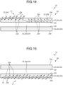
- the first linear member 22A the one linear member 22 indicated by a dot-and-dash line
- the other linear member 22 indicated by a dashed line will be referred to as the second linear member 22B.
- the plurality of unfixed portions 22b continuous via the fixed portions 22a in the first linear member 22A is disposed to be exposed through the front surface 20e of the first layer 20k.
- the plurality of unfixed portions 22b continuous via the fixed portions 22a is disposed inside the first layer 20k.
- the material of the first linear member 22A and the material of the second linear member 22B may be the same as each other, or may be different from each other.
- the width of the first linear member 22A and the width of the second linear member 22B may be the same as each other, or may be different from each other.
- first linear member 22A disposed to be exposed through the front surface 20e of the first layer 20k and the second linear member 22B disposed inside the first layer 20k are disposed separately from each other, it is possible to partially change the physical properties of the upper 2A by changing the material, thickness, or the like of the first linear member 22A and the second linear member 22B.
- the two divided linear members 22 may be integrated into one linear member 22. That is, at least one linear member of the plurality of linear members 22 may be a single member that has a region in which the plurality of unfixed portions 22b continuous via the fixed portions 22a is disposed to be exposed only through the front surface 20e of the first layer 20k, and a region in which the plurality of unfixed portions 22b continuous via the fixed portions 22a is disposed only inside the first layer 20k. With this arrangement, the processing cost and the environmental load can be reduced.
- FIG. 15 is a cross-sectional view illustrating the upper 2A of a shoe 1A according to a fourth modification of the second embodiment of the present disclosure, and is a view corresponding to a cross-sectional view taken along the line III-III illustrated in FIG. 2 .
- the plurality of unfixed portions 22b continuous via the fixed portions 22a illustrated in FIG. 15 is disposed to be exposed through the front surface 20e of the second layer 20m.
- the unfixed portions 22b do not affect the design of the upper 2A, or hardly affects the design of the upper 2A.
- the design of the first layer 20k of the base member 20 is easily maintained as the design of the appearance of the upper 2A.
- the abrasion strength and the tensile rigidity of the inner surfaces of the upper 2A can be enhanced.
- the plurality of unfixed portions 22b continuous via the fixed portions 22a is disposed to be exposed through the front surface 20e of the second layer 20m, and in a case where the linear members 22 formed with a material having a pleasant feeling are used, the feeling to be felt by the foot of the wearer touching the linear members 22 can be enhanced.
- FIG. 16 is a cross-sectional view illustrating the upper 2A of a shoe 1A according to a fifth modification of the second embodiment of the present disclosure, and is a view corresponding to a cross-sectional view taken along the line III-III illustrated in FIG. 2 .
- the plurality of unfixed portions 22b continuous via the fixed portions 22a illustrated in FIG. 16 is disposed inside the second layer 20m.
- the unfixed portions 22b do not affect the design of the upper 2A, or hardly affects the design of the upper 2A.
- the design of the first layer 20k of the base member 20 is easily maintained as the design of the appearance of the upper 2A.
- the abrasion strength and the tensile rigidity of the second layer 20m of the upper 2A can be enhanced while the feeling to be felt by the wearer touching the base member 20 with the foot is maintained as the feeling of touching the upper 2A.
- FIG. 17 is a cross-sectional view illustrating the upper 2A of a shoe 1A according to a sixth modification of the second embodiment of the present disclosure, and is a view corresponding to a cross-sectional view taken along the line III-III illustrated in FIG. 2 .
- the plurality of unfixed portions 22b continuous via the fixed portions 22a illustrated in FIG. 17 is disposed to be exposed through the front surface 20e of the second layer 20m, or is disposed inside the second layer 20m.
- FIG. 17 illustrates a state in which two linear members 22 disposed separately are arranged in the length direction of the linear members 22.
- the first linear member 22A the one linear member 22 indicated by a dot-and-dash line
- the other linear member 22 indicated by a dashed line will be referred to as the second linear member 22B.
- the plurality of unfixed portions 22b continuous via the fixed portions 22a in the first linear member 22A is disposed to be exposed through the front surface 20e of the second layer 20m.
- the plurality of unfixed portions 22b continuous via the fixed portions 22a is disposed inside the second layer 20m.
- the material of the first linear member 22A and the material of the second linear member 22B may be the same as each other, or may be different from each other.
- the width of the first linear member 22A and the width of the second linear member 22B may be the same as each other, or may be different from each other. In this modification, the same effects as any of the above-described embodiments and modifications can be achieved.
- the two divided linear members 22 may be integrated into one linear member 22. That is, at least one linear member of the plurality of linear members 22 may be a single member that has a region in which the plurality of unfixed portions 22b continuous via the fixed portions 22a is disposed to be exposed only through the front surface 20e of the second layer 20m, and a region in which the plurality of unfixed portions 22b continuous via the fixed portions 22a is disposed only inside the second layer 20m. With this arrangement, the processing cost and the environmental load can be reduced.
- FIG. 18 is a cross-sectional view illustrating the upper 2A of a shoe 1A according to a seventh modification of the second embodiment of the present disclosure, and is a view corresponding to a cross-sectional view taken along the line III-III illustrated in FIG. 2 .
- the plurality of unfixed portions 22b continuous via the fixed portions 22a illustrated in FIG. 18 is disposed to be exposed through the front surface 20e of the first layer 20k, or is disposed inside the third layer 20n.
- FIG. 18 illustrates a state in which two linear members 22 disposed separately are arranged in the length direction of the linear members 22.
- the first linear member 22A the one linear member 22 indicated by a dot-and-dash line
- the other linear member 22 indicated by a solid line will be referred to as the second linear member 22B.
- the plurality of unfixed portions 22b continuous via the fixed portions 22a in the first linear member 22A is disposed to be exposed through the front surface 20e of the first layer 20k.
- the entire second linear member 22B is disposed inside the third layer 20n.
- the second linear member 22B also includes a plurality of fixed portions 22a and a plurality of unfixed portions 22b, though not illustrated in the drawing.
- the fixed portions 22a of the second linear member 22B are portions woven in the portion connecting the first layer 20k and the second layer 20m in the third layer 20n.
- the unfixed portions 22b are portions not interwoven with the yarns 20g inside the third layer 20n.
- the plurality of unfixed portions 22b continuous via the fixed portions 22a is disposed inside the third layer 20n.
- the material of the first linear member 22A and the material of the second linear member 22B may be the same as each other, or may be different from each other.
- the width of the first linear member 22A and the width of the second linear member 22B may be the same as each other, or may be different from each other.
- the unfixed portions 22b do not affect the design of the upper 2A, or hardly affects the design of the upper 2A. Accordingly, in the portion of the base member 20 in which the second linear members 22B are disposed, the design of the first layer 20k of the base member 20 is easily maintained as the design of the appearance of the upper 2A. As a result, the flexural rigidity and the like of the upper 2A can be partially enhanced without any change in the appearance of the base member 20.
- the plurality of unfixed portions 22b continuous via the fixed portions 22a is disposed inside the third layer 20n, it is possible to enhance the tensile rigidity of the third layer 20n of the upper 2A while maintaining the feeling to be felt by the wearer touching the base member 20 with the foot as the feeling of touching the upper 2A.
- the two divided linear members 22 may be integrated into one linear member 22. That is, at least one linear member of the plurality of linear members 22 may be a single member that has a region in which the plurality of unfixed portions 22b continuous via the fixed portions 22a is disposed to be exposed only through the front surface 20e of the first layer 20k, and a region in which the plurality of unfixed portions 22b continuous via the fixed portions 22a is disposed only inside the third layer 20n. With this arrangement, the processing cost and the environmental load can be reduced.
- FIG. 19 is a cross-sectional view illustrating the upper 2A of a shoe 1A according to an eighth modification of the second embodiment of the present disclosure, and is a view corresponding to a cross-sectional view taken along the line III-III illustrated in FIG. 2 .
- the plurality of unfixed portions 22b continuous via the fixed portions 22a illustrated in FIG. 19 is disposed inside the first layer 20k, or is disposed inside the third layer 20n.
- FIG. 19 illustrates a state in which two linear members 22 disposed separately are arranged in the length direction of the linear members 22.
- the first linear member 22A the one linear member 22 indicated by a dashed line
- the other linear member 22 indicated by a solid line will be referred to as the second linear member 22B.
- the plurality of unfixed portions 22b continuous via the fixed portions 22a is disposed inside the first layer 20k.
- the entire second linear member 22B is disposed inside the third layer 20n.
- the second linear member 22B also includes a plurality of fixed portions 22a and a plurality of unfixed portions 22b, though not illustrated in the drawing.
- the fixed portions 22a of the second linear member 22B are portions woven in the portion connecting the first layer 20k and the second layer 20m in the third layer 20n.
- the unfixed portions 22b are portions not interwoven with the yarns 20g inside the third layer 20n.
- the plurality of unfixed portions 22b continuous via the fixed portions 22a is disposed inside the third layer 20n.
- the material of the first linear member 22A and the material of the second linear member 22B may be the same as each other, or may be different from each other.
- the width of the first linear member 22A and the width of the second linear member 22B may be the same as each other, or may be different from each other. In this modification, the same effects as any of the above-described embodiments and modifications can be achieved.
- the two divided linear members 22 may be integrated into one linear member 22. That is, at least one linear member of the plurality of linear members 22 may be a single member that has a region in which the plurality of unfixed portions 22b continuous via the fixed portions 22a is disposed only inside the first layer 20k, and a region in which the plurality of unfixed portions 22b continuous via the fixed portions 22a is disposed only inside the third layer 20n. With this arrangement, the processing cost and the environmental load can be reduced.
- FIG. 20 is a cross-sectional view illustrating the upper 2A of a shoe 1A according to a ninth modification of the second embodiment of the present disclosure, and is a view corresponding to a cross-sectional view taken along the line III-III illustrated in FIG. 2 .
- the plurality of unfixed portions 22b continuous via the fixed portions 22a illustrated in FIG. 20 is disposed to be exposed through the front surface 20e of the first layer 20k, is disposed inside the first layer 20k, or is disposed inside the third layer 20n.
- FIG. 20 illustrates a state in which three linear members 22 disposed separately are arranged in the length direction of the linear members 22.
- the linear member 22 indicated by a dot-and-dash line will be referred to as the first linear member 22A
- the linear member 22 indicated by a dashed line will be referred to as the second linear member 22B
- the linear member 22 indicated by a solid line will be referred to as the third linear member 22C.
- the plurality of unfixed portions 22b continuous via the fixed portions 22a in the first linear member 22A is disposed to be exposed through the front surface 20e of the first layer 20k.
- the plurality of unfixed portions 22b continuous via the fixed portions 22a is disposed inside the first layer 20k.
- the entire third linear member 22C is disposed inside the third layer 20n. In a case where the entire third linear member 22C is disposed inside the third layer 20n, the third linear member 22C also includes a plurality of fixed portions 22a and a plurality of unfixed portions 22b, though not illustrated in the drawing.
- the fixed portions 22a of the third linear member 22C are portions woven in the portion connecting the first layer 20k and the second layer 20m in the third layer 20n.
- the unfixed portions 22b are portions not interwoven with the yarns 20g inside the third layer 20n.
- the plurality of unfixed portions 22b continuous via the fixed portions 22a are disposed inside the third layer 20n.
- the third linear member 22C is disposed between the first linear member 22A and the second linear member 22B.
- the third linear member 22C connects the first linear member 22A and the second linear member 22B.
- the material of the first linear member 22A, the material of the second linear member 22B, and the material of the third linear member 22C may be the same as one another, or may be different from one another.
- the thickness of the first linear member 22A, the thickness of the second linear member 22B, and the thickness of the third linear member 22C may be the same as one another, or may be different from one another. In this modification, the same effects as any of the above-described embodiments and modifications can be achieved.
- the three divided linear members 22 may be integrated into one linear member 22. That is, at least one linear member of the plurality of linear members 22 may be a single member that has a region in which the plurality of unfixed portions 22b continuous via the fixed portions 22a is disposed to be exposed only through the front surface 20e of the first layer 20k, a region in which the plurality of unfixed portions 22b continuous via the fixed portions 22a is disposed only inside the first layer 20k, and a region in which the plurality of unfixed portions 22b continuous via the fixed portions 22a is disposed only inside the third layer 20n.
- the processing cost and the environmental load can be reduced.
- FIG. 21 is a cross-sectional view illustrating the upper 2A of a shoe 1A according to a tenth modification of the second embodiment of the present disclosure, and is a view corresponding to a cross-sectional view taken along the line III-III illustrated in FIG. 2 .
- the plurality of unfixed portions 22b continuous via the fixed portions 22a illustrated in FIG. 21 is disposed to be exposed through the front surface 20e of the second layer 20m, or is disposed inside the third layer 20n.
- FIG. 21 illustrates a state in which two linear members 22 disposed separately are arranged in the length direction of the linear members 22.
- the linear member 22 indicated by a dot-and-dash line will be referred to as the first linear member 22A
- the linear member 22 indicated by a solid line will be referred to as the second linear member 22B.
- the plurality of unfixed portions 22b continuous via the fixed portions 22a in the first linear member 22A is disposed to be exposed through the front surface 20e of the second layer 20m.
- the entire second linear member 22B is disposed inside the third layer 20n.
- the second linear member 22B also includes a plurality of fixed portions 22a and a plurality of unfixed portions 22b, though not illustrated in the drawing.
- the fixed portions 22a of the second linear member 22B are portions woven in the portion connecting the first layer 20k and the second layer 20m in the third layer 20n.
- the unfixed portions 22b are portions not interwoven with the yarns 20g inside the third layer 20n.
- the plurality of unfixed portions 22b continuous via the fixed portions 22a is disposed inside the third layer 20n.
- the material of the first linear member 22A and the material of the second linear member 22B may be the same as each other, or may be different from each other.
- the width of the first linear member 22A and the width of the second linear member 22B may be the same as each other, or may be different from each other. In this modification, the same effects as any of the above-described embodiments and modifications can be achieved.
- the two divided linear members 22 may be integrated into one linear member 22. That is, at least one linear member of the plurality of linear members 22 may be a single member that has a region in which the plurality of unfixed portions 22b continuous via the fixed portions 22a is disposed to be exposed only through the front surface 20e of the second layer 20m, and a region in which the plurality of unfixed portions 22b continuous via the fixed portions 22a is disposed only inside the third layer 20n. With this arrangement, the processing cost and the environmental load can be reduced.
- FIG. 22 is a cross-sectional view illustrating the upper 2A of a shoe 1A according to an eleventh modification of the second embodiment of the present disclosure, and is a view corresponding to a cross-sectional view taken along the line III-III illustrated in FIG. 2 .
- the plurality of unfixed portions 22b continuous via the fixed portions 22a illustrated in FIG. 22 is disposed inside the second layer 20m, or is disposed inside the third layer 20n.
- FIG. 22 illustrates a state in which two linear members 22 disposed separately are arranged in the length direction of the linear members 22.
- the linear member 22 indicated by a dashed line will be referred to as the first linear member 22A
- the linear member 22 indicated by a solid line will be referred to as the second linear member 22B.
- the plurality of unfixed portions 22b continuous via the fixed portions 22a is disposed inside the second layer 20m.
- the entire second linear member 22B is disposed inside the third layer 20n.
- the second linear member 22B also includes a plurality of fixed portions 22a and a plurality of unfixed portions 22b, though not illustrated in the drawing.
- the fixed portions 22a of the second linear member 22B are portions woven in the portion connecting the first layer 20k and the second layer 20m in the third layer 20n.
- the unfixed portions 22b are portions not interwoven with the yarns 20g inside the third layer 20n.
- the plurality of unfixed portions 22b continuous via the fixed portions 22a is disposed inside the third layer 20n.
- the material of the first linear member 22A and the material of the second linear member 22B may be the same as each other, or may be different from each other.
- the width of the first linear member 22A and the width of the second linear member 22B may be the same as each other, or may be different from each other. In this modification, the same effects as any of the above-described embodiments and modifications can be achieved.
- the two divided linear members 22 may be integrated into one linear member 22. That is, at least one linear member of the plurality of linear members 22 may be a single member that has a region in which the plurality of unfixed portions 22b continuous via the fixed portions 22a is disposed only inside the second layer 20m, and a region in which the plurality of unfixed portions 22b continuous via the fixed portions 22a is disposed only inside the third layer 20n. With this arrangement, the processing cost and the environmental load can be reduced.
- FIG. 23 is a cross-sectional view illustrating the upper 2A of a shoe 1A according to a twelfth modification of the second embodiment of the present disclosure, and is a view corresponding to a cross-sectional view taken along the line III-III illustrated in FIG. 2 .
- the plurality of unfixed portions 22b continuous via the fixed portions 22a illustrated in FIG. 23 is disposed to be exposed through the front surface 20e of the second layer 20m, is disposed inside the second layer 20m, or is disposed inside the third layer 20n.
- FIG. 23 illustrates a state in which three linear members 22 disposed separately are arranged in the length direction of the linear members 22.
- the linear member 22 indicated by a dot-and-dash line will be referred to as the first linear member 22A
- the linear member 22 indicated by a dashed line will be referred to as the second linear member 22B
- the linear member 22 indicated by a solid line will be referred to as the third linear member 22C.
- the plurality of unfixed portions 22b continuous via the fixed portions 22a in the first linear member 22A is disposed to be exposed through the front surface 20e of the second layer 20m.
- the plurality of unfixed portions 22b continuous via the fixed portions 22a is disposed inside the second layer 20m.
- the entire third linear member 22C is disposed inside the third layer 20n. In a case where the entire third linear member 22C is disposed inside the third layer 20n, the third linear member 22C also includes a plurality of fixed portions 22a and a plurality of unfixed portions 22b, though not illustrated in the drawing.
- the fixed portions 22a of the third linear member 22C are portions woven in the portion connecting the first layer 20k and the second layer 20m in the third layer 20n.
- the unfixed portions 22b are portions not interwoven with the yarns 20g inside the third layer 20n.
- the plurality of unfixed portions 22b continuous via the fixed portions 22a are disposed inside the third layer 20n.
- the third linear member 22C is disposed between the first linear member 22A and the second linear member 22B.
- the third linear member 22C connects the first linear member 22A and the second linear member 22B.
- the material of the first linear member 22A, the material of the second linear member 22B, and the material of the third linear member 22C may be the same as one another, or may be different from one another.
- the thickness of the first linear member 22A, the thickness of the second linear member 22B, and the thickness of the third linear member 22C may be the same as one another, or may be different from one another. In this modification, the same effects as any of the above-described embodiments and modifications can be achieved.
- the three divided linear members 22 may be integrated into one linear member 22. That is, at least one linear member of the plurality of linear members 22 may be a single member that has a region in which the plurality of unfixed portions 22b continuous via the fixed portions 22a is disposed to be exposed only through the front surface 20e of the second layer 20m, a region in which the plurality of unfixed portions 22b continuous via the fixed portions 22a is disposed only inside the second layer 20m, and a region in which the plurality of unfixed portions 22b continuous via the fixed portions 22a is disposed only inside the third layer 20n.
- the processing cost and the environmental load can be reduced.
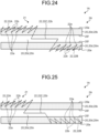
- FIG. 24 is a cross-sectional view illustrating the upper 2A of a shoe 1A according to a thirteenth modification of the second embodiment of the present disclosure, and is a view corresponding to a cross-sectional view taken along the line III-III illustrated in FIG. 2 .
- the plurality of unfixed portions 22b continuous via the fixed portions 22a illustrated in FIG. 24 is disposed to be exposed through the front surface 20e of the first layer 20k, is disposed to be exposed through the front surface 20e of the second layer 20m, or is disposed inside the third layer 20n.
- FIG. 24 illustrates a state in which three linear members 22 disposed separately are arranged in the length direction of the linear members 22.
- the one linear member 22 indicated by a dot-and-dash line will be referred to as the first linear member 22A
- the other linear member 22 indicated by a dot-and-dash line will be referred to as the second linear member 22B
- the linear member 22 indicated by a solid line will be referred to as the third linear member 22C.
- the plurality of unfixed portions 22b continuous via the fixed portions 22a in the first linear member 22A is disposed to be exposed through the front surface 20e of the first layer 20k.
- the plurality of unfixed portions 22b continuous via the fixed portions 22a in the second linear member 22B is disposed to be exposed through the front surface 20e of the second layer 20m.
- the entire third linear member 22C is disposed inside the third layer 20n. In a case where the entire third linear member 22C is disposed inside the third layer 20n, the third linear member 22C also includes a plurality of fixed portions 22a and a plurality of unfixed portions 22b, though not illustrated in the drawing.
- the fixed portions 22a of the third linear member 22C are portions woven in the portion connecting the first layer 20k and the second layer 20m in the third layer 20n.
- the unfixed portions 22b are portions not interwoven with the yarns 20g inside the third layer 20n.
- the plurality of unfixed portions 22b continuous via the fixed portions 22a are disposed inside the third layer 20n.
- the third linear member 22C is disposed between the first linear member 22A and the second linear member 22B.
- the third linear member 22C connects the first linear member 22A and the second linear member 22B.
- the material of the first linear member 22A, the material of the second linear member 22B, and the material of the third linear member 22C may be the same as one another, or may be different from one another.
- the thickness of the first linear member 22A, the thickness of the second linear member 22B, and the thickness of the third linear member 22C may be the same as one another, or may be different from one another. In this modification, the same effects as any of the above-described embodiments and modifications can be achieved.
- the three divided linear members 22 may be integrated into one linear member 22. That is, at least one linear member of the plurality of linear members 22 may be a single member that has a region in which the plurality of unfixed portions 22b continuous via the fixed portions 22a is disposed to be exposed only through the front surface 20e of the first layer 20k, a region in which the plurality of unfixed portions 22b continuous via the fixed portions 22a is disposed to be exposed only through the front surface 20e of the second layer 20m, and a region in which the plurality of unfixed portions 22b continuous via the fixed portions 22a is disposed only inside the third layer 20n.
- the processing cost and the environmental load can be reduced.
- FIG. 25 is a cross-sectional view illustrating the upper 2A of a shoe 1A according to a fourteenth modification of the second embodiment of the present disclosure, and is a view corresponding to a cross-sectional view taken along the line III-III illustrated in FIG. 2 .
- the plurality of unfixed portions 22b continuous via the fixed portions 22a illustrated in FIG. 25 is disposed to be exposed through the front surface 20e of the first layer 20k, is disposed inside the second layer 20m, or is disposed inside the third layer 20n.
- FIG. 25 illustrates a state in which three linear members 22 disposed separately are arranged in the length direction of the linear members 22.
- the linear member 22 indicated by a dot-and-dash line will be referred to as the first linear member 22A
- the linear member 22 indicated by a dashed line will be referred to as the second linear member 22B
- the linear member 22 indicated by a solid line will be referred to as the third linear member 22C.
- the plurality of unfixed portions 22b continuous via the fixed portions 22a in the first linear member 22A is disposed to be exposed through the front surface 20e of the first layer 20k.
- the plurality of unfixed portions 22b continuous via the fixed portions 22a is disposed inside the second layer 20m.
- the entire third linear member 22C is disposed inside the third layer 20n. In a case where the entire third linear member 22C is disposed inside the third layer 20n, the third linear member 22C also includes a plurality of fixed portions 22a and a plurality of unfixed portions 22b, though not illustrated in the drawing.
- the fixed portions 22a of the third linear member 22C are portions woven in the portion connecting the first layer 20k and the second layer 20m in the third layer 20n.
- the unfixed portions 22b are portions not interwoven with the yarns 20g inside the third layer 20n.
- the plurality of unfixed portions 22b continuous via the fixed portions 22a are disposed inside the third layer 20n.
- the third linear member 22C is disposed between the first linear member 22A and the second linear member 22B.
- the third linear member 22C connects the first linear member 22A and the second linear member 22B.
- the material of the first linear member 22A, the material of the second linear member 22B, and the material of the third linear member 22C may be the same as one another, or may be different from one another.
- the thickness of the first linear member 22A, the thickness of the second linear member 22B, and the thickness of the third linear member 22C may be the same as one another, or may be different from one another. In this modification, the same effects as any of the above-described embodiments and modifications can be achieved.
- the three divided linear members 22 may be integrated into one linear member 22. That is, at least one linear member of the plurality of linear members 22 may be a single member that has a region in which the plurality of unfixed portions 22b continuous via the fixed portions 22a is disposed to be exposed only through the front surface 20e of the first layer 20k, a region in which the plurality of unfixed portions 22b continuous via the fixed portions 22a is disposed only inside the second layer 20m, and a region in which the plurality of unfixed portions 22b continuous via the fixed portions 22a is disposed only inside the third layer 20n.
- the processing cost and the environmental load can be reduced.
- FIG. 26 is a cross-sectional view illustrating the upper 2A of a shoe 1A according to a fifteenth modification of the second embodiment of the present disclosure, and is a view corresponding to a cross-sectional view taken along the line III-III illustrated in FIG. 2 .
- the plurality of unfixed portions 22b continuous via the fixed portions 22a illustrated in FIG. 26 is disposed to be exposed through the front surface 20e of the second layer 20m, is disposed inside the first layer 20k, or is disposed inside the third layer 20n.
- FIG. 26 illustrates a state in which three linear members 22 disposed separately are arranged in the length direction of the linear members 22.
- the linear member 22 indicated by a dot-and-dash line will be referred to as the first linear member 22A
- the linear member 22 indicated by a dashed line will be referred to as the second linear member 22B
- the linear member 22 indicated by a solid line will be referred to as the third linear member 22C.
- the plurality of unfixed portions 22b continuous via the fixed portions 22a in the first linear member 22A is disposed to be exposed through the front surface 20e of the second layer 20m.
- the plurality of unfixed portions 22b continuous via the fixed portions 22a is disposed inside the first layer 20k.
- the entire third linear member 22C is disposed inside the third layer 20n. In a case where the entire third linear member 22C is disposed inside the third layer 20n, the third linear member 22C also includes a plurality of fixed portions 22a and a plurality of unfixed portions 22b, though not illustrated in the drawing.
- the fixed portions 22a of the third linear member 22C are portions woven in the portion connecting the first layer 20k and the second layer 20m in the third layer 20n.
- the unfixed portions 22b are portions not interwoven with the yarns 20g inside the third layer 20n.
- the plurality of unfixed portions 22b continuous via the fixed portions 22a are disposed inside the third layer 20n.
- the third linear member 22C is disposed between the first linear member 22A and the second linear member 22B.
- the third linear member 22C connects the first linear member 22A and the second linear member 22B.
- the material of the first linear member 22A, the material of the second linear member 22B, and the material of the third linear member 22C may be the same as one another, or may be different from one another.
- the thickness of the first linear member 22A, the thickness of the second linear member 22B, and the thickness of the third linear member 22C may be the same as one another, or may be different from one another. In this modification, the same effects as any of the above-described embodiments and modifications can be achieved.
- the three divided linear members 22 may be integrated into one linear member 22. That is, at least one linear member of the plurality of linear members 22 may be a single member that has a region in which the plurality of unfixed portions 22b continuous via the fixed portions 22a is disposed to be exposed only through the front surface 20e of the second layer 20m, a region in which the plurality of unfixed portions 22b continuous via the fixed portions 22a is disposed only inside the first layer 20k, and a region in which the plurality of unfixed portions 22b continuous via the fixed portions 22a is disposed only inside the third layer 20n.
- the processing cost and the environmental load can be reduced.
- the plurality of unfixed portions 22b continuous via the fixed portions 22a is only required to be exposed through the front surface 20e of at least one layer 20d, or be disposed inside at least one layer 20d.
- the design of the base member 20 can be used as it is or some other design can be applied to the base member 20, and the physical properties of the base member 20 can be used as they are or some other physical properties can be imparted to the base member 20. That is, as the positions of the linear members 22 in the base member 20 can be selected as appropriate in the present embodiment, the physical properties of the upper 2A can be partially changed freely while the range of expression of the design of the upper 2A is widened.
- the linear members 22 can be disposed at least one of the following positions: on the front surface 20e of the first layer 20k, inside the first layer 20k, inside the third layer 20n, inside the second layer 20m, and on the front surface 20e of the second layer 20m illustrated in FIG. 25 .
- the region is divided into a region in which the unfixed portions 22b can be clearly seen, a region in which the unfixed portions 22b can be somewhat seen, and a region in which the unfixed portions 22b cannot be seen. Accordingly, it is possible to express a design having a height difference not only in the in-plane direction of the upper 2A but also in the thickness direction of the upper 2A. That is, a three-dimensional design including the thickness direction of the upper 2A and the in-plane direction of the upper 2A can be created.
- the layer 20d is a porous member such as a mesh
- the unfixed portions 22b disposed inside the third layer 20n, inside the second layer 20m, and on the front surface 20e of the second layer 20m might be visible.
- the linear members 22 may be disposed at least one of the following positions: on the front surface 20e of the first layer 20k, inside the first layer 20k, inside the third layer 20n, inside the second layer 20m, and on the front surface 20e of the second layer 20m.
- the visibility of the unfixed portions 22b changes depending on the positions of the unfixed portions 22b in the base member 20.
- the linear members 22 can be made to appear blurred, and a design having a height difference in the thickness direction of the upper 2A can be expressed.
- the layout of the unfixed portions 22b is not limited to the example illustrated in FIG. 10 , and may be changed as appropriate.
- at least one unfixed portion of the plurality of unfixed portions 22b may be disposed across two or more wales of the base member 20, or two or more courses of the base member 20.
- the number of wales of the base member 20 crossed by the unfixed portions 22b may be larger than the number of courses of the base member 20 crossed by the unfixed portions 22b.
- a design that cannot be expressed with a knitted fabric can be applied to the appearance of the upper 2A.
- the base member 20 is formed with a material that is easy to stretch
- the linear members 22 are formed with a material that is difficult to stretch
- an upper 2A that is easy to stretch in the course direction (second direction) but is difficult to stretch in the wale direction (first direction) can be manufactured.
- the number of courses of the base member 20 crossed by the unfixed portions 22b and the number of wales of the base member 20 crossed by the unfixed portions 22b may be the same.
- the base member 20 is a knitted fabric in which a plurality of yarns 20g is knitted.
- a woven fabric in which a plurality of yarns 20g is woven, or a composition in which a plurality of yarns 20g is combined may be used, for example.
- An upper according to a first aspect includes: a cloth-like base member that includes one layer having a front surface and a back surface facing in the opposite direction from the front surface; and a plurality of linear members that are disposed side by side in the base member and are formed independently of each other, in which
- An upper according to a second aspect is the upper according to the first aspect, in which at least one linear member of the plurality of linear members is a single member that includes: a first region in which a plurality of the unfixed portions continuous via the fixed portions is disposed to be exposed only through the front surface of the layer; and a second region in which a plurality of the unfixed portions continuous via the fixed portions is disposed to be exposed only through the back surface of the layer, or is disposed only inside the layer.
- An upper according to a third aspect is the upper according to the first or second aspect, in which the base member is a knitted fabric in which a plurality of yarns is knitted, a woven fabric in which a plurality of yarns is woven, or a composition in which a plurality of yarns is combined, and the length of the unfixed portions is 3 mm or greater.
- An upper according to a fourth aspect is the upper according to the third aspect, in which the thickness of at least one linear member of the plurality of linear members and the thickness of the yarns of the base member are different from each other.
- An upper according to a fifth aspect is the upper according to the third aspect, in which the material of at least one linear member of the plurality of linear members and the material of the yarns of the base member are different from each other.
- An upper according to a sixth aspect is the upper according to the third aspect, in which the melting point of a material of at least one linear member of the plurality of linear members is lower than the melting point of the material of the base member.
- An upper according to a seventh aspect is the upper according to the first or second aspect, in which the base member is a knitted fabric in which a plurality of yarns is knitted, and at least one unfixed portion of the plurality of unfixed portions is disposed across two or more wales of the base member, or two or more courses of the base member.
- An upper according to an eighth aspect is the upper according to the seventh aspect, in which the number of courses of the base member crossed by the unfixed portions is larger than the number of wales of the base member crossed by the unfixed portion.
- An upper according to a ninth aspect is the upper according to the seventh aspect, in which the number of wales of the base member crossed by the unfixed portions is larger than the number of courses of the base member crossed by the unfixed portion.
- An upper according to a tenth aspect is the upper according to any one of the first to ninth aspects, in which the unfixed portions are exposed through the front surface located on the opposite side from the foot of the wearer in the base member.
- An upper according to an eleventh aspect is the upper according to any one of the first to ninth aspects, in which the unfixed portions are exposed through the back surface located on the side of the foot of the wearer in the base member.
- An upper according to a twelfth aspect includes: a cloth-like base member that includes two or more layers each having a front surface and a back surface facing in the opposite direction from the front surface; and a plurality of linear members that are disposed side by side in the base member and are formed independently of each other, in which
- An upper according to a thirteenth aspect is the upper according to the twelfth aspect, in which at least one linear member of the plurality of linear members is a single member.
- An upper according to a fourteenth aspect is the upper according to the twelfth or thirteenth aspect, in which the base member is a knitted fabric in which a plurality of yarns is knitted, a woven fabric in which a plurality of yarns is woven, or a composition in which a plurality of yarns is combined, and the length of the unfixed portions is 3 mm or greater.
- An upper according to a fifteenth aspect is the upper according to the fourteenth aspect, in which the thickness of at least one linear member of the plurality of linear members and the thickness of the yarns of the base member are different from each other.
- An upper according to a sixteenth aspect is the upper according to the fourteenth aspect, in which the material of at least one linear member of the plurality of linear members and the material of the yarns of the base member are different from each other.
- An upper according to a seventeenth aspect is the upper according to the fourteenth aspect, in which the melting point of a material of at least one linear member of the plurality of linear members is lower than the melting point of the material of the base member.
- An upper according to an eighteenth aspect is the upper according to the twelfth or thirteenth aspect, in which the base member is a knitted fabric in which a plurality of yarns is knitted, and at least one unfixed portion of the plurality of unfixed portions is disposed across two or more wales of the base member, or two or more courses of the base member.
- An upper according to a nineteenth aspect is the upper according to the eighteenth aspect, in which the number of courses of the base member crossed by the unfixed portions is larger than the number of wales of the base member crossed by the unfixed portion.
- An upper according to a twentieth aspect is the upper according to the eighteenth aspect, in which the number of wales of the base member crossed by the unfixed portions is larger than the number of courses of the base member crossed by the unfixed portion.
- An upper according to a twenty-first aspect is the upper according to any one of the twelfth to twentieth aspects, in which the unfixed portions are exposed through the front surface of the layer farthest from the foot of the wearer in the base member.
- An upper according to a twenty-second aspect is the upper according to any one of the twelfth to twentieth aspects, in which the unfixed portions are exposed through the front surface of the layer located closest to the side of the foot of the wearer in the base member.
- An upper according to a twenty-third aspect is the upper according to any one of the twelfth to twentieth aspects, in which the base member includes a first layer, a second layer disposed at a distance from the first layer, and a third layer located between the first layer and the second layer, and the unfixed portions are disposed in the third layer.
- a shoe according to a twenty-fourth aspect includes the upper according to any one of the first to twenty-third aspects, and a sole of the shoe, the sole being located below the upper.
Landscapes
- Footwear And Its Accessory, Manufacturing Method And Apparatuses (AREA)
Abstract
Description
- The present disclosure relates to an upper and a shoe including the upper.
- Conventionally, to enhance the design of the upper by decorating the upper, or to control physical properties such as tensile rigidity and abrasion strength of the upper, embroideries are formed on the upper (see
Patent Literature 1, for example). - The upper includes a cloth-like base member. The base member normally includes one or more layers each including a front surface and a back surface. As disclosed in
Patent Literature 1, a conventional embroidery is formed by sewing yarns onto the base member after the base member is manufactured. Hereinafter, a "yarn" fixed to the base member will be referred to as a "linear member". - To widen the range of expression in the design of the upper and to partially change the physical properties of the upper, the positions of the linear members in the base member are preferably selectable as desired.
- Patent Literature 1:
JP 2020-525088 W - With the conventional embroideries, however, in a case where the base member is formed with one layer, the linear members are disposed over the front surface, the back surface, and the inside of the layer of the base member without fail, and, in a case where the base member is formed with two or more layers, the linear members are disposed over the respective layers of the base member without fail. Therefore, the conventional embroideries have a problem in that the degree of freedom in selecting the positions of the linear members in the base member is low.
- The present disclosure has been made in view of the above, and aims to obtain an upper capable of increasing the degree of freedom in selecting the positions of linear members in the base member.
- In order to solve the above problem and achieve the object, an upper comprising: a cloth-like base member that includes one layer having a front surface and a back surface facing in an opposite direction from the front surface; and a plurality of linear members that are disposed side by side in the base member and are formed independently of each other, wherein each linear member of the plurality of linear members includes: a plurality of fixed portions that are fixed to the layer, and are disposed at a distance from each other; and a plurality of unfixed portions that are located between adjacent ones of the fixed portions, and are not fixed to the layer, each linear member of the plurality of linear members is folded back and forth in an in-plane direction of the layer, and a plurality of the unfixed portions continuous via the fixed portions is disposed to be exposed through at least one of the front surface or the back surface of the layer, or is disposed inside the layer.
- An upper according to the present disclosure has an effect of increasing the degree of freedom in selecting the positions of linear members in the base member.
-
-
FIG. 1 is a developed view illustrating the upper of a shoe according to a first embodiment of the present disclosure. -
FIG. 2 is a perspective view illustrating the shoe according to the first embodiment of the present disclosure. -
FIG. 3 is a cross-sectional view taken along the line III-III illustrated inFIG. 2 . -
FIG. 4 is a view when the upper is viewed from an arrow X illustrated inFIG. 3 . -
FIG. 5 is a cross-sectional view illustrating the upper of a shoe according to a comparative example, and is a view illustrating a state in which embroideries are disposed on the upper in which the layer of the base member is a single layer. -
FIG. 6 is a cross-sectional view illustrating the upper of a shoe according to a first modification of the first embodiment of the present disclosure, and is a view corresponding to a cross-sectional view taken along the line III-III illustrated inFIG. 2 . -
FIG. 7 is a cross-sectional view illustrating the upper of a shoe according to a second modification of the first embodiment of the present disclosure, and is a view corresponding to a cross-sectional view taken along the line III-III illustrated inFIG. 2 . -
FIG. 8 is a view illustrating the upper of a shoe according to a third modification of the first embodiment of the present disclosure, and is a view corresponding to a view of the upper seen from the arrow X illustrated inFIG. 3 . -
FIG. 9 is a cross-sectional view illustrating the upper of a shoe according to a second embodiment of the present disclosure, and is a view corresponding to a cross-sectional view taken along the line III-III illustrated inFIG. 2 . -
FIG. 10 is a view illustrating the upper of the shoe according to the second embodiment of the present disclosure, and is a view corresponding to a view of the upper seen from an arrow X illustrated inFIG. 9 . -
FIG. 11 is a cross-sectional view illustrating the upper of a shoe according to a comparative example, and is a view illustrating a state in which embroideries are disposed on the upper in which the base member has three layers. -
FIG. 12 is a cross-sectional view illustrating the upper of a shoe according to a first modification of the second embodiment of the present disclosure, and is a view corresponding to a cross-sectional view taken along the line III-III illustrated inFIG. 2 . -
FIG. 13 is a cross-sectional view illustrating the upper of a shoe according to a second modification of the second embodiment of the present disclosure, and is a view corresponding to a cross-sectional view taken along the line III-III illustrated inFIG. 2 . -
FIG. 14 is a cross-sectional view illustrating the upper of a shoe according to a third modification of the second embodiment of the present disclosure, and is a view corresponding to a cross-sectional view taken along the line III-III illustrated inFIG. 2 . -
FIG. 15 is a cross-sectional view illustrating the upper of a shoe according to a fourth modification of the second embodiment of the present disclosure, and is a view corresponding to a cross-sectional view taken along the line III-III illustrated inFIG. 2 . -
FIG. 16 is a cross-sectional view illustrating the upper of a shoe according to a fifth modification of the second embodiment of the present disclosure, and is a view corresponding to a cross-sectional view taken along the line III-III illustrated inFIG. 2 . -
FIG. 17 is a cross-sectional view illustrating the upper of a shoe according to a sixth modification of the second embodiment of the present disclosure, and is a view corresponding to a cross-sectional view taken along the line III-III illustrated inFIG. 2 . -
FIG. 18 is a cross-sectional view illustrating the upper of a shoe according to a seventh modification of the second embodiment of the present disclosure, and is a view corresponding to a cross-sectional view taken along the line III-III illustrated inFIG. 2 . -
FIG. 19 is a cross-sectional view illustrating the upper of a shoe according to an eighth modification of the second embodiment of the present disclosure, and is a view corresponding to a cross-sectional view taken along the line III-III illustrated inFIG. 2 . -
FIG. 20 is a cross-sectional view illustrating the upper of a shoe according to a ninth modification of the second embodiment of the present disclosure, and is a view corresponding to a cross-sectional view taken along the line III-III illustrated inFIG. 2 . -
FIG. 21 is a cross-sectional view illustrating the upper of a shoe according to a tenth modification of the second embodiment of the present disclosure, and is a view corresponding to a cross-sectional view taken along the line III-III illustrated inFIG. 2 . -
FIG. 22 is a cross-sectional view illustrating the upper of a shoe according to an eleventh modification of the second embodiment of the present disclosure, and is a view corresponding to a cross-sectional view taken along the line III-III illustrated inFIG. 2 . -
FIG. 23 is a cross-sectional view illustrating the upper of a shoe according to a twelfth modification of the second embodiment of the present disclosure, and is a view corresponding to a cross-sectional view taken along the line III-III illustrated inFIG. 2 . -
FIG. 24 is a cross-sectional view illustrating the upper of a shoe according to a thirteenth modification of the second embodiment of the present disclosure, and is a view corresponding to a cross-sectional view taken along the line III-III illustrated inFIG. 2 . -
FIG. 25 is a cross-sectional view illustrating the upper of a shoe according to a fourteenth modification of the second embodiment of the present disclosure, and is a view corresponding to a cross-sectional view taken along the line III-III illustrated inFIG. 2 . -
FIG. 26 is a cross-sectional view illustrating the upper of a shoe according to a fifteenth modification of the second embodiment of the present disclosure, and is a view corresponding to a cross-sectional view taken along the line III-III illustrated inFIG. 2 . - The following is a detailed description of embodiments of an upper and a shoe according to the present disclosure, with reference to the drawings. Note that the present disclosure is not limited by this embodiments. In the description below, the same portions are denoted by the same reference numerals, and explanation of them will be repeated.
-
FIG. 1 is a developed view illustrating the upper 2 of ashoe 1 according to a first embodiment of the present disclosure. In the drawings includingFIG. 1 , only theshoe 1 for the left foot is illustrated. Since theshoe 1 for the left foot has a structure symmetrical with the shoe for the right foot, only theshoe 1 for the left foot is described in the present embodiment, and explanation of theshoe 1 for the right foot is not made herein. In the description below, a direction in which a shoe center axis C, which is a perpendicular line extending through the center of theshoe 1 in a planar view of theshoe 1, extends will be referred to as the longitudinal direction, and a direction orthogonal to the longitudinal direction in a planar view of theshoe 1 will be referred to as the foot width direction. - In the description below, of the longitudinal direction, the direction from the heel toward the toe of the
shoe 1 will be referred to as the fore direction, and the direction from the toe toward the heel of theshoe 1 will be referred to as the rear direction. - In the description below, the median side in the anatomical normal position of the foot will be referred to as the medial foot side, and the side opposite to the median side in the anatomical normal position of the foot will be referred to as the lateral foot side. That is, the side closer to the median line in the anatomical normal position will be referred to as the medial foot side, and the side farther from the median line in the anatomical normal position will be referred to as the lateral foot side.
- In the description below, the vertical direction means the direction orthogonal to both the longitudinal direction and the foot width direction, unless otherwise specified.
- The upper 2 includes an upper fore foot position R1 covering the fore foot position of a foot of a wearer having a standard body shape, an upper middle foot position R2 covering the middle foot position of the foot of the wearer having a standard body shape, and an upper rear foot position R3 covering the rear foot position of the foot of the wearer having a standard body shape. The upper fore foot position R1, the upper middle foot position R2, and the upper rear foot position R3 are successively present in this order in the direction from the fore to the rear of the upper 2.
- The line that extends in the foot width direction and passes through a position corresponding to about 30% to 40% of the dimension of the upper 2 in the longitudinal direction of the upper 2 from the fore end is defined as a first boundary line S1, and the line that extends the foot width direction and passes through a position corresponding to about 73% to 83% of the dimension of the upper 2 in the longitudinal direction from the fore end of the upper 2 is defined as a second boundary line S2. The first boundary line S1 is a line that extends substantially along the MP joint of the wearer having a standard body shape. The second boundary line S2 is a line that extends substantially along the Chopart's joint of the wearer having a standard body shape. The upper fore foot position R1 is a portion located on the fore side of the first boundary line S1. The upper middle foot position R2 is a portion located between the first boundary line S1 and the second boundary line S2. The upper rear foot position R3 is a portion located on the rear side of the second boundary line S2.
-
FIG. 2 is a perspective view illustrating theshoe 1 according to the first embodiment of the present disclosure. Theshoe 1 is preferably a shoe for running, but may be a shoe for some other sport, a shoe for walking, a shoe for climbing, or the like. Theshoe 1 includes the upper 2 and a sole 3. - The upper 2 is located above the sole 3. The upper 2 includes a
base member 20, a linearmember placement region 21, ashoe tongue 23, and ashoelace 24. - The
base member 20 covers a portion on the instep side of the foot of the wearer. Afoot insertion opening 20a and athroat portion 20b are disposed at an upper portion of thebase member 20. Thefoot insertion opening 20a is an opening for allowing the foot of the wearer to enter the inside of thebase member 20. Thethroat portion 20b is an opening that communicates with thefoot insertion opening 20a and extends in the fore direction from thefoot insertion opening 20a. A plurality oflace hole portions 20c separated from one another in the longitudinal direction is disposed on both side edges of thethroat portion 20b in the foot width direction. InFIG. 2 , only thelace hole portions 20c disposed at the side edge on the lateral foot side of thethroat portion 20b are illustrated. Thelace hole portions 20c only needs to enable theshoelace 24 to pass therethrough. Thelace hole portions 20c are through holes penetrating thebase member 20 in the thickness direction of thebase member 20, for example. - In
FIGS. 1 and2 , to clarify the range of the linearmember placement region 21, dot hatching is applied to the linearmember placement region 21. The linearmember placement region 21 plays a role of decorating the upper 2 and a role of partially changing the physical properties of the upper 2. Details of thebase member 20 and the linearmember placement region 21 will be described later. - The
shoe tongue 23 is a member for protecting the instep of the foot of the wearer. Theshoe tongue 23 covers thethroat portion 20b inside thebase member 20. Theshoe tongue 23 is secured to thebase member 20 by stitching, welding, bonding, or a combination thereof. Thebase member 20 and theshoe tongue 23 are knitted fabrics in which yarns are rolled into a chain-like shape and chain-like portions are hooked to one another to form a cloth, woven fabrics in which warp yarns and weft yarns cross each other at a certain angle to form a cloth, or compositions in which three or more braid yarns cross one another and run obliquely to form a cloth, for example. In particular, in theshoe 1 in which air permeability and lightweight properties are required, thebase member 20 and theshoe tongue 23 are preferably double raschel warp knitted fabrics knitted with polyester yarns. Note that the materials of thebase member 20 and theshoe tongue 23 are not limited to the materials mentioned as examples. - The
shoelace 24 is a string-like member that passes alternately through thelace hole portions 20c disposed at one side edge in the foot width direction of thethroat portion 20b and thelace hole portions 20c disposed at the other side edge in the foot width direction. Theshoelace 24 is detachably attached to thebase member 20. - Note that, in the present embodiment, the upper 2 including the
shoe tongue 23 and theshoelace 24 is described as an example, but the upper 2 may have a monosock structure in which the portion corresponding to theshoe tongue 23 is integrated with the ankle portion of thebase member 20. Also, the means for bringing thebase member 20 into close contact with the foot may be a hook-and-loop fastener, for example, instead of theshoelace 24. In a case where the means for bringing thebase member 20 into close contact with the foot is a hook-and-loop fastener, thelace hole portions 20c are not disposed in thebase member 20. - The sole 3 is located below the upper 2. The sole 3 covers the sole of the wearer. The sole 3 is secured to the
base member 20 by stitching, welding, bonding, or a combination thereof. The sole 3 includes anoutsole 30 and amidsole 31. The lower face of theoutsole 30 serves as aground contact face 30a to be in contact with the ground. Themidsole 31 is located on the upper face of theoutsole 30, and has cushioning properties. Note that theoutsole 30 may be integrated with themidsole 31. Theoutsole 30 integrated with themidsole 31 is also referred to as the "unisole". - Although not illustrated, the sole 3 includes an inner sole that covers the lower opening of the
base member 20. The inner sole is secured to the upper face of themidsole 31 by adhesion or welding. The inner sole is secured to the lower edge of thebase member 20 by stitching. Although not illustrated, theshoe 1 may include an insole. In a case where theshoe 1 includes an insole, the insole is placed on the sole 3 inside the upper 2. Note that the sole 3 may have a structure that excludes the inner sole. - Next, the
base member 20 and the linearmember placement region 21 are described in greater detail, with reference toFIGS. 1 to 4 .FIG. 3 is a cross-sectional view taken along the line III-III illustrated inFIG. 2 .FIG. 4 is a view when the upper 2 is viewed from an arrow X illustrated inFIG. 3 . - As illustrated in
FIG. 1 , thebase member 20 includes the upper fore foot position R1, the upper middle foot position R2, and the upper rear foot position R3. As illustrated inFIG. 2 , thebase member 20 is disposed over the entire region of the upper 2, except for theshoe tongue 23 and theshoelace 24. As illustrated inFIG. 3 , thebase member 20 is a cloth-like member having one layer 20d. The layer 20d includes afront surface 20e, and aback surface 20f facing in the opposite direction from thefront surface 20e. - The
front surface 20e is the surface facing the outside of the upper 2. In other words, thefront surface 20e is the surface located on the opposite side from the foot of the wearer. Theback surface 20f is the surface facing the inside of the upper 2. In other words, theback surface 20f is the surface located on the side of the foot of the wearer. As illustrated inFIG. 4 , in the present embodiment, thebase member 20 is a knitted fabric in which a plurality of yarns 20g is knitted. Thebase member 20 includes a plurality ofwales 20h extending in a first direction and a plurality ofcourses 20i extending in a second direction orthogonal to the first direction. One of the first direction and the second direction coincides with the longitudinal direction, and the other one of the first direction and the second direction coincides with the foot width direction. - As illustrated in
FIG. 1 , the linearmember placement regions 21 are disposed in the upper fore foot position R1 and the upper middle foot position R2 of thebase member 20. In the present embodiment, the linearmember placement regions 21 are disposed at the positions indicated by dot hatching inFIG. 1 . The positions of the linearmember placement regions 21 are not limited to the illustrated examples. As illustrated inFIG. 4 , the linearmember placement regions 21 are the regions in which a plurality oflinear members 22 are disposed. The plurality oflinear members 22 is arranged side by side in thebase member 20 and are disposed independently of one another. The plurality oflinear members 22 is arranged in the in-plane direction of thebase member 20. Each linear member of the plurality oflinear members 22 is folded back and forth in the in-plane direction of thebase member 20. Thelinear members 22 have a variation range of 3 mm or wider in the longitudinal direction or the foot width direction. - The
linear members 22 and the yarns 20g of thebase member 20 are yarns obtained by bundling a plurality of fibers, linear resins, twisted yarns, or the like, for example. The materials of thelinear members 22 and the yarns 20g of thebase member 20 are polyester, polyurethane-based thermoplastic elastomer, polyurethane, nylon, spandex, Kevlar (registered trademark), ultra-high molecular weight polyethylene, single covered Yarn (SCY) or double covered Yarn (DCY) covered with polyurethane, or the like, for example. - The material of some or all of the plurality of
linear members 22 and the material of the yarns 20g of thebase member 20 may be the same as each other, or be different from each other. For example, the material of at least one linear member of the plurality oflinear members 22 and the material of the yarns 20g of thebase member 20 may be different from each other. The width of some or all of the plurality oflinear members 22 and the width of the yarns 20g of thebase member 20 may be the same as each other, or be different from each other. For example, the width of at least one linear member of the plurality oflinear members 22 and the width of the yarns 20g of thebase member 20 may be different from each other. - The melting point of the material of at least one linear member of the plurality of
linear members 22 is preferably lower than the melting point of the material of thebase member 20. For example, some or all of the plurality oflinear members 22 may be yarns having a lower melting point than that of the yarns 20g of thebase member 20. Also, some or all of the plurality oflinear members 22 may be composite yarns containing fibers having different melting points. In particular, a core-in-sheath structure in which a core material (fiber) having a high melting point is covered with a low-melting-point material is preferably used for some or all of the plurality oflinear members 22. In this arrangement, when thelinear members 22 are subjected to a heat treatment at a temperature equal to or higher than the melting point of the low-melting-point material, the low-melting-point material is locally melted and solidified. Thus, the tensile rigidity of the upper 2 can be further enhanced. - Each linear member of the plurality of
linear members 22 includes a plurality of fixedportions 22a fixed to the layer 20d, and a plurality ofunfixed portions 22b not fixed to the layer 20d. The fixedportions 22a are disposed apart from one another. The fixedportions 22a are portions that are passed throughaperture portions 20j disposed in thebase member 20 and are entangled with the yarns 20g. Theaperture portions 20j are circular holes. Theaperture portions 20j are disposed, being entangled with some of the adjacent loops of thebase member 20. Theunfixed portions 22b are disposed apart from one another. Theunfixed portions 22b are located between the adjacent fixedportions 22a. - The length L of the
unfixed portions 22b in the first direction may be set as appropriate, but is preferably greater than 3 mm. Each unfixed portion of the plurality ofunfixed portions 22b is disposed across one wale of thebase member 20, and is disposed across two courses of thebase member 20. The number of courses of thebase member 20 crossed by theunfixed portions 22b is larger than the number of wales of thebase member 20 crossed by theunfixed portions 22b. - As illustrated in
FIG. 3 , the plurality oflinear members 22 is disposed to be exposed through thefront surface 20e of the layer 20d, or is disposed to be exposed through theback surface 20f of the layer 20d.FIG. 3 illustrates a state in which twolinear members 22 disposed separately are arranged in the length direction of thelinear members 22. In the description below, in a case where the twolinear members 22 are distinguished, the onelinear member 22 indicated by a dot-and-dash line will be referred to as the first linear member 22A, and the otherlinear member 22 indicated by a dashed line will be referred to as the second linear member 22B. - The plurality of
unfixed portions 22b continuous via the fixedportions 22a in the first linear member 22A is disposed to be exposed through thefront surface 20e of the layer 20d. Theunfixed portions 22b of the first linear member 22A are exposed through thefront surface 20e of thebase member 20 located on the opposite side from the foot of the wearer. In the second linear member 22B, the plurality ofunfixed portions 22b continuous via the fixedportions 22a is disposed to be exposed through theback surface 20f of the layer 20d. Theunfixed portions 22b of the second linear member 22B are exposed through theback surface 20f of thebase member 20 located on the side of the foot of the wearer. The material of the first linear member 22A and the material of the second linear member 22B may be the same as each other, or may be different from each other. The width of the first linear member 22A and the width of the second linear member 22B may be the same as each other, or may be different from each other. - In the manufacturing of the upper 2, the
base member 20 and the linearmember placement regions 21 can be formed in one step using a dedicated machine such as a warp knitting machine. - Next, the effects of the upper 2 and the
shoe 1 according to the present embodiment are described. -
FIG. 5 is a cross-sectional view illustrating the upper 110 of ashoe 100 according to a comparative example, and is a view illustrating a state in which embroideries are disposed on the upper 110 in which the layer 20d of thebase member 20 is a single layer. As illustrated inFIG. 5 , in a conventional embroidery, theunfixed portions 22b of alinear member 22 are alternately exposed through thefront surface 20e and theback surface 20f of the layer 20d. That is, in the conventional embroidery, when theunfixed portions 22b of alinear member 22 are exposed through thefront surface 20e of the layer 20d, thelinear member 22 passes through the inside of the layer 20d, and theunfixed portions 22b of thelinear member 22 are also exposed through theback surface 20f of the layer 20d without fail, so that thelinear member 22 is disposed across thefront surface 20e, theback surface 20f, and the inside of the layer 20d of thebase member 20 without fail. - In the present embodiment, as illustrated in
FIG. 3 , each linear member of the plurality oflinear members 22 includes a plurality of fixedportions 22a that are fixed to the layer 20d and are disposed apart from each other, and a plurality ofunfixed portions 22b that are located between the adjacent fixedportions 22a and are not fixed to the layer 20d. In the present embodiment, the plurality ofunfixed portions 22b continuous via the fixedportions 22a is disposed to be exposed through thefront surface 20e of the layer 20d, or is disposed to be exposed through theback surface 20f of the layer 20d. With this arrangement, the plurality ofunfixed portions 22b of onelinear member 22 can be continuously exposed through thefront surface 20e of the layer 20d, and the plurality ofunfixed portions 22b of onelinear member 22 can be continuously exposed through theback surface 20f of the layer 20d. Thus, the degree of freedom in selecting the positions of thelinear members 22 in thebase member 20 can be made higher than those with conventional embroideries. - In a case where the plurality of
unfixed portions 22b continuous via the fixedportions 22a is disposed to be exposed through thefront surface 20e of the layer 20d, any design can be freely applied to the appearance of the upper 2. Further, in a case where the plurality ofunfixed portions 22b continuous via the fixedportions 22a is disposed to be exposed through thefront surface 20e of the layer 20d, and in a case where thelinear members 22 having high abrasion strength are used, the abrasion strength and the tensile rigidity of the outer surface of the upper 2 can be enhanced while the feeling to be felt by the wearer touching thebase member 20 with the foot is maintained as the feeling of touching the upper 2. In a case where the plurality ofunfixed portions 22b continuous via the fixedportions 22a is disposed to be exposed through theback surface 20f of the layer 20d, theunfixed portions 22b do not affect the design of the upper 2, or hardly affects the design of the upper 2. Thus, the design of thebase member 20 is easily maintained as the design of the appearance of the upper 2. Furthermore, in a case where the plurality ofunfixed portions 22b continuous via the fixedportions 22a is disposed to be exposed through theback surface 20f of the layer 20d, and in a case where thelinear members 22 having high abrasion strength are used, the abrasion strength and the tensile rigidity of the inner surfaces of the upper 2 can be enhanced. Further, in a case where the plurality ofunfixed portions 22b continuous via the fixedportions 22a is disposed to be exposed through theback surface 20f of the layer 20d, and in a case where thelinear members 22 formed with a material having a pleasant feeling are used, the feeling to be felt by the foot of the wearer touching thelinear members 22 can be enhanced. That is, as the positions of thelinear members 22 in thebase member 20 can be selected as appropriate in the present embodiment, the physical properties of the upper 2 can be partially changed freely while the range of expression of the design of the upper 2 is widened. - As illustrated in
FIG. 5 , in a conventional embroidery, in a case where theunfixed portions 22b are seen through thefront surface 20e of the layer 20d, theunfixed portions 22b are alternately exposed through thefront surface 20e and theback surface 20f of the layer 20d, and therefore, irregularities appear on theback surface 20f of the layer 20d. Since the irregularities adversely affect the contact of the foot, it is necessary to bond a backing material to theback surface 20f of the layer 20d. In that case, however, the weight of theshoe 1 increases. In this regard, in a case where theunfixed portions 22b are seen through thefront surface 20e of the layer 20d in the present embodiment as illustrated inFIG. 3 , the plurality ofunfixed portions 22b is continuously exposed through thefront surface 20e of the layer 20d, like the first linear member 22A. Accordingly, irregularities do not appear on theback surface 20f of the layer 20d, and the upper 2 having a preferred feeling of foot contact can be provided without the use of any backing material. - Since the formation of the
base member 20 and the formation of the linearmember placement regions 21 illustrated inFIG. 3 can be performed in one step in the present embodiment, the number of manufacturing steps, the amount of waste material, and the like of the upper 2 can be reduced, and thus, the cost and the environmental load can be reduced. - To enhance the tensile rigidity of the upper 2 with the
linear members 22 illustrated inFIG. 4 , it is necessary to dispose eachlinear member 22 across two or more of the courses and two or more of the wales constituting thebase member 20. In the case of a knitted fabric, the maximum size of the courses and the wales is about 3 mm, and therefore, the variation range of thelinear members 22 is preferably 3 mm or wider as in the present embodiment. - To realize a variety of design and a variety of physical properties of the upper 2 as in the present embodiment by using a conventional technique for forming embroideries on the upper and welding yarns to the upper, a backing material and an adhesive are required. In the present embodiment, it is possible to realize a variety of design and a variety of physical properties of the upper 2 only with the
linear members 22, and there is no need to use a backing material and an adhesive. Thus, it is possible to make the weight of the upper 2 lighter than that with a conventional technique. - In the present embodiment, as illustrated in
FIG. 3 , the first linear member 22A disposed to be exposed through thefront surface 20e of the layer 20d, and the second linear member 22B disposed to be exposed through theback surface 20f of the layer 20d are disposed separately from each other. With this arrangement, it is possible to change the physical properties of the upper 2, by changing the material, the thickness, and the like of the first linear member 22A and the second linear member 22B. - In the case of a knitted fabric, the size of the stitches is 3 mm at the maximum. Since the length L of the
unfixed portions 22b illustrated inFIG. 4 exceeds 3 mm in the present embodiment, a design that cannot be expressed with a knitted fabric can be applied to the appearance of the upper 2. - When the thickness of at least one linear member of the plurality of
linear members 22 illustrated inFIG. 4 and the thickness of the yarns 20g of thebase member 20 are made different from each other, physical properties such as abrasion strength and tensile rigidity can be made different between thelinear members 22 and the yarns 20g. Accordingly, the physical properties of the upper 2 at the portions where thelinear members 22 are disposed, and the physical properties of the upper 2 at the portions where thelinear members 22 are not disposed can be made different from each other. - When the material of at least one linear member of the plurality of
linear members 22 illustrated inFIG. 4 and the material of the yarns 20g of thebase member 20 are made different from each other, physical properties such as abrasion strength and tensile rigidity can be made different between thelinear members 22 and the yarns 20g. Accordingly, the physical properties of the upper 2 at the portions where thelinear members 22 are disposed, and the physical properties of the upper 2 at the portions where thelinear members 22 are not disposed can be made different from each other. - In the present embodiment, as illustrated in
FIG. 4 , at least one unfixed portion of the plurality ofunfixed portions 22b is disposed across two or more courses of thebase member 20. Thus, a design that cannot be expressed with a knitted fabric can be applied to the appearance of the upper 2, and the tensile rigidity of the upper 2 in the course direction can be increased. - In the present embodiment, as illustrated in
FIG. 4 , the number of courses of thebase member 20 crossed by theunfixed portions 22b is larger than the number of wales of thebase member 20 crossed by theunfixed portions 22b. Thus, in a case where thebase member 20 is formed with a material that is easy to stretch, and thelinear members 22 are formed with a material that is difficult to stretch, for example, an upper 2 that is easy to stretch in the wale direction (first direction) but is difficult to stretch in the course direction (second direction) can be manufactured. - Next, modifications of the first embodiment are described.
- The two divided
linear members 22 illustrated inFIG. 3 may be onelinear member 22 as illustrated inFIG. 6. FIG. 6 is a cross-sectional view illustrating the upper 2 of ashoe 1 according to a first modification of the first embodiment of the present disclosure, and is a view corresponding to a cross-sectional view taken along the line III-III illustrated inFIG. 2 . - The
linear member 22 is a single member having afirst region 22c and asecond region 22d. Thefirst region 22c is a region in which a plurality ofunfixed portions 22b continuous via fixedportions 22a is disposed to be exposed only through thefront surface 20e of the layer 20d. Thesecond region 22d is a region in which a plurality ofunfixed portions 22b continuous via fixedportions 22a is disposed to be exposed only through theback surface 20f of the layer 20d. - Since the
linear member 22 is a single member having thefirst region 22c and thesecond region 22d in this modification, it is possible to reduce the processing cost and the environmental load, compared with those in a case where the portion corresponding to thefirst region 22c and the portion corresponding to thesecond region 22d are formed separately from each other. Since thelinear member 22 is a single member having thefirst region 22c and thesecond region 22d in this modification, when thefirst region 22c is pulled, tension can be applied to thesecond region 22d, and fitting between the foot and the upper 2 can be enhanced. Note that it is only required that at least one linear member of the plurality oflinear members 22 is a single member having thefirst region 22c and thesecond region 22d. - In the present embodiment, the plurality of
unfixed portions 22b continuous via the fixedportions 22a is disposed to be exposed through thefront surface 20e of the layer 20d, or is arranged to be exposed through theback surface 20f of the layer 20d, as illustrated inFIG. 3 . However, someunfixed portions 22b may be disposed inside the layer 20d as illustrated inFIG. 7 . That is, the plurality ofunfixed portions 22b continuous via the fixedportions 22a is only required to be exposed through at least either thefront surface 20e or theback surface 20f of the layer 20d, or be disposed inside the layer 20d.FIG. 7 is a cross-sectional view illustrating the upper 2 of ashoe 1 according to a second modification of the first embodiment of the present disclosure, and is a view corresponding to a cross-sectional view taken along the line III-III illustrated inFIG. 2 . - As illustrated in
FIG. 7 , the configuration of the first linear member 22A is the same as that of the first embodiment. In this modification, the entire second linear member 22B is disposed inside the layer 20d. In a case where the entire second linear member 22B is disposed inside the layer 20d, the second linear member 22B also includes a plurality of fixedportions 22a and a plurality ofunfixed portions 22b. The fixedportions 22a are portions interwoven with yarns 20g inside the layer 20d. Theunfixed portions 22b are portions not interwoven with the yarns 20g inside the layer 20d. In the second linear member 22B, the plurality ofunfixed portions 22b continuous via the fixedportions 22a is disposed inside the layer 20d. Theunfixed portions 22b of the second linear member 22B are not exposed through thefront surface 20e and theback surface 20f of thebase member 20. As the formation of thebase member 20 and the formation of the linearmember placement regions 21 can be performed in one step in this modification, thelinear members 22 can be disposed inside the layer 20d of thebase member 20. - In a case where the plurality of
unfixed portions 22b continuous via the fixedportions 22a is disposed inside the layer 20d, theunfixed portions 22b are somewhat visible when the exterior of the upper 2 is viewed, but a design similar to thebase member 20 is easily maintained as the design of the appearance of the upper 2. Also, in a case where the plurality ofunfixed portions 22b continuous via the fixedportions 22a is disposed inside the layer 20d, it is possible to enhance the tensile rigidity of the upper 2 while maintaining the feeling to be felt by the wearer touching thebase member 20 with the foot, as the feeling of touching the upper 2. Depending on whether the positions of the plurality ofunfixed portions 22b continuous via the fixedportions 22a are located on thefront surface 20e of the layer 20d, theback surface 20f of the layer 20d, or inside the layer 20d, the design of thebase member 20 can be used as it is or some other design can be applied to thebase member 20, and the physical properties of thebase member 20 can be used as they are or some other physical properties can be imparted to thebase member 20. - Note that a
linear member 22 to be exposed through thefront surface 20e of the layer 20d and alinear member 22 to be disposed inside the layer 20d may be integrally formed. In the case of such a configuration, thelinear members 22 are formed as a single member having a first region and a second region. The first region is a region in which a plurality ofunfixed portions 22b continuous via fixedportions 22a is disposed to be exposed only through thefront surface 20e of the layer 20d. The second region is a region in which a plurality ofunfixed portions 22b continuous via fixedportions 22a is disposed only inside the layer 20d. - The
linear members 22 can also be disposed on thefront surface 20e of the layer 20d, inside the layer 20d, and on theback surface 20f of the layer 20d illustrated inFIG. 7 . With this arrangement, the region is divided into a region in which theunfixed portions 22b can be clearly seen, a region in which theunfixed portions 22b can be somewhat seen, and a region in which theunfixed portions 22b cannot be seen. Accordingly, it is possible to express a design having a height difference not only in the in-plane direction of the upper 2 but also in the thickness direction of the upper 2. That is, a three-dimensional design including the thickness direction of the upper 2 and the in-plane direction of the upper 2 can be created. - For example, in a case where the layer 20d is a porous member such as a mesh, in a case where the thickness of the layer 20d is small, and in a case where the layer 20d is transparent, the
unfixed portions 22b disposed inside the layer 20d and on theback surface 20f of the layer 20d might be visible. In such a case, thelinear members 22 may be disposed on thefront surface 20e of the layer 20d, inside the layer 20d, and on theback surface 20f of the layer 20d. With such arrangement, the visibility of theunfixed portions 22b changes depending on the positions of theunfixed portions 22b in thebase member 20. Thus, thelinear members 22 can be made to appear blurred, and a design having a height difference in the thickness direction of the upper 2 can be expressed. - The layout of the
unfixed portions 22b is not limited to the example illustrated inFIG. 4 , and may be changed as appropriate. For example, at least one unfixed portion of the plurality ofunfixed portions 22b may be disposed across two or more wales of thebase member 20, or two or more courses of thebase member 20. - For example, the
unfixed portions 22b may be arranged as illustrated inFIG. 8. FIG. 8 is a view illustrating the upper 2 of ashoe 1 according to a third modification of the first embodiment of the present disclosure, and is a view corresponding to a view of the upper 2 seen from the arrow X illustrated inFIG. 3 . Each unfixed portion of a plurality ofunfixed portions 22b is disposed across five wales of thebase member 20, and is disposed across one course of thebase member 20. The number of wales of thebase member 20 crossed by theunfixed portions 22b is larger than the number of courses of thebase member 20 crossed by theunfixed portions 22b. In this modification, a design that cannot be expressed with a knitted fabric can be applied to the appearance of the upper 2. In this modification, in a case where thebase member 20 is formed with a material that is easy to stretch, and thelinear members 22 are formed with a material that is difficult to stretch, for example, an upper 2 that is easy to stretch in the course direction (second direction) but is difficult to stretch in the wale direction (first direction) can be manufactured. Note that the number of courses of thebase member 20 crossed by theunfixed portions 22b and the number of wales of thebase member 20 crossed by theunfixed portions 22b may be the same. - In the present embodiment, the
base member 20 is a knitted fabric in which a plurality of yarns 20g is knitted. However, a woven fabric in which a plurality of yarns 20g is woven, or a composition in which a plurality of yarns 20g is combined may be used, for example. - A
shoe 1A according to a second embodiment is now described with reference toFIGS. 9 and10 .FIG. 9 is a cross-sectional view illustrating the upper 2A of theshoe 1A according to the second embodiment of the present disclosure, and is a view corresponding to a cross-sectional view taken along the line III-III illustrated inFIG. 2 .FIG. 10 is a view illustrating the upper 2A of theshoe 1A according to the second embodiment of the present disclosure, and is a view corresponding to a view of the upper 2A seen from an arrow X illustrated inFIG. 9 . Theshoe 1A according to the second embodiment differs from theshoe 1 according to the first embodiment in that thebase member 20 has two or more layers 20d. - As illustrated in
FIG. 9 , thebase member 20 is a cloth-like member having two or more layers 20d. The number of layers 20d of thebase member 20 is three in the present embodiment, but may be changed as appropriate. Thebase member 20 includes a first layer 20k, a second layer 20m disposed at a distance from the first layer 20k, and a third layer 20n located between the first layer 20k and the second layer 20m. - The first layer 20k is located on the outermost side in the
base member 20. In other words, the first layer 20k is the layer 20d farthest from the foot of the wearer in thebase member 20. The second layer 20m is located on the innermost side in thebase member 20. In other words, the second layer 20m is the layer 20d located closest to the side of the foot of the wearer in thebase member 20. The third layer 20n is located between the first layer 20k and the second layer 20m. The third layer 20n is a layer 20d that connects the first layer 20k and the second layer 20m, and prevents the first layer 20k and the second layer 20m from coming into contact with each other. Although not illustrated in the drawings, the third layer 20n includes a portion connecting the first layer 20k and the second layer 20m. In the present embodiment, the third layer 20n includes a space formed between the first layer 20k and the second layer 20m. Each of the first layer 20k and the second layer 20m includes afront surface 20e, and aback surface 20f facing in the opposite direction from thefront surface 20e. - The
front surface 20e of the first layer 20k is a surface facing the outside of the upper 2A in the first layer 20k. In other words, thefront surface 20e of the first layer 20k is a surface located on the opposite side from the foot of the wearer in the first layer 20k. Theback surface 20f of the first layer 20k is a surface facing the inside of the upper 2A in the first layer 20k. In other words, in the first layer 20k, theback surface 20f of the first layer 20k is a surface located on the side of the foot of the wearer. - The
front surface 20e of the second layer 20m is a surface facing the inside of the upper 2A in the second layer 20m. In other words, thefront surface 20e of the second layer 20m is a surface located on the side of the foot of the wearer in the second layer 20m. Theback surface 20f of the second layer 20m is a surface facing the outside of the upper 2A in the second layer 20m. In other words, theback surface 20f of the second layer 20m is a surface located on the opposite side from the foot of the wearer in the second layer 20m. - In the present embodiment, the surface of each layer 20d exposed to the inside or the outside of the upper 2A is the
front surface 20e, and the surface of each layer 20d exposed to neither of the inside and the outside of the upper 2A is theback surface 20f. As illustrated inFIG. 10 , in the present embodiment, thebase member 20 is a knitted fabric in which a plurality of yarns 20g is knitted. Thebase member 20 includes a plurality ofwales 20h extending in a first direction and a plurality ofcourses 20i extending in a second direction orthogonal to the first direction. One of the first direction and the second direction coincides with the longitudinal direction, and the other one of the first direction and the second direction coincides with the foot width direction. - As in the first embodiment described above, the linear
member placement regions 21 are disposed in the upper fore foot position R1 and the upper middle foot position R2 of thebase member 20. The linearmember placement regions 21 are disposed at the positions indicated by dot hatching inFIG. 1 . The positions of the linearmember placement regions 21 are not limited to the illustrated examples. As illustrated inFIG. 10 , the linearmember placement regions 21 are the regions in which a plurality oflinear members 22 is disposed. The plurality oflinear members 22 is arranged side by side in thebase member 20 and are disposed independently of one another. The plurality oflinear members 22 is arranged in the in-plane direction of thebase member 20. Each linear member of the plurality oflinear members 22 is folded back and forth in the in-plane direction of thebase member 20. Thelinear members 22 have a variation range of 3 mm or wider in the longitudinal direction or the foot width direction. - The
linear members 22 and the yarns 20g of thebase member 20 are yarns obtained by bundling a plurality of fibers, linear resins, twisted yarns, or the like, for example. The materials of thelinear members 22 and the yarns 20g of thebase member 20 are polyester, polyurethane-based thermoplastic elastomer, polyurethane, nylon, spandex, Kevlar (registered trademark), ultra-high molecular weight polyethylene, single covered Yarn (SCY) or double covered Yarn (DCY) covered with polyurethane, or the like, for example. - The material of some or all of the plurality of
linear members 22 and the material of the yarns 20g of thebase member 20 may be the same as each other, or be different from each other. For example, the material of at least one linear member of the plurality oflinear members 22 and the material of the yarns 20g of thebase member 20 may be different from each other. The width of some or all of the plurality oflinear members 22 and the width of the yarns 20g of thebase member 20 may be the same as each other, or be different from each other. For example, the width of at least one linear member of the plurality oflinear members 22 and the width of the yarns 20g of thebase member 20 may be different from each other. - The melting point of the material of at least one linear member of the plurality of
linear members 22 is preferably lower than the melting point of the material of thebase member 20. For example, some or all of the plurality oflinear members 22 may be yarns having a lower melting point than that of the yarns 20g of thebase member 20. Also, some or all of the plurality oflinear members 22 may be composite yarns containing fibers having different melting points. In particular, a core-in-sheath structure in which a core material (fiber) having a high melting point is covered with a low-melting-point material is preferably used for some or all of the plurality oflinear members 22. In this arrangement, when thelinear members 22 are subjected to a heat treatment at a temperature equal to or higher than the melting point of the low-melting-point material, the low-melting-point material is locally melted and solidified. Thus, the tensile rigidity of the upper 2 can be further enhanced. - Each linear member of the plurality of
linear members 22 includes a plurality of fixedportions 22a fixed to at least one layer 20d, and a plurality ofunfixed portions 22b not fixed to any layer 20d. The fixedportions 22a are disposed apart from one another. The fixedportions 22a are portions that are passed throughaperture portions 20j disposed in thebase member 20 and are entangled with the yarns 20g. Theaperture portions 20j are circular holes. Theaperture portions 20j are disposed, being entangled with some of the adjacent loops of thebase member 20. Theunfixed portions 22b are disposed apart from one another. Theunfixed portions 22b are located between the adjacent fixedportions 22a. - The length L of the
unfixed portions 22b in the first direction may be set as appropriate, but is preferably greater than 3 mm. Each unfixed portion of the plurality ofunfixed portions 22b is disposed across one wale of thebase member 20, and is disposed across two courses of thebase member 20. The number of courses of thebase member 20 crossed by theunfixed portions 22b is larger than the number of wales of thebase member 20 crossed by theunfixed portions 22b. - As illustrated in
FIG. 9 , the plurality oflinear members 22 is disposed to be exposed through thefront surface 20e of at least one layer 20d. The plurality ofunfixed portions 22b continuous via the fixedportions 22a is disposed to be exposed through thefront surface 20e of the first layer 20k. Theunfixed portions 22b are exposed through thefront surface 20e of the first layer 20k farthest from the foot of the wearer in thebase member 20. - In the manufacturing of the upper 2A, the
base member 20 and the linearmember placement regions 21 can be formed in one step using a dedicated machine such as a warp knitting machine. - Next, the effects of the upper 2A and the
shoe 1A according to the present embodiment are described. -
FIG. 11 is a cross-sectional view illustrating the upper 210 of ashoe 200 according to a comparative example, and is a view illustrating a state in which embroideries are disposed on the upper 210 in which thebase member 20 has three layers 20d. As illustrated inFIG. 11 , in a conventional embroidery, theunfixed portions 22b of alinear member 22 are alternately exposed through thefront surface 20e of the first layer 20k and thefront surface 20e of the second layer 20m. That is, in the conventional embroidery, when theunfixed portions 22b of alinear member 22 are exposed through thefront surface 20e of the first layer 20k, thelinear member 22 passes through the third layer 20n, and theunfixed portions 22b of thelinear member 22 are also exposed through thefront surface 20e of the second layer 20m without fail, so that thelinear member 22 is disposed across the respective layers 20d of thebase member 20 without fail. - In the present embodiment, as illustrated in
FIG. 9 , each linear member of the plurality oflinear members 22 includes a plurality of fixedportions 22a that are fixed to at least one layer 20d and are disposed apart from each other, and a plurality ofunfixed portions 22b that are located between the adjacent fixedportions 22a and are not fixed to any layer 20d. In the present embodiment, the plurality ofunfixed portions 22b continuous via the fixedportions 22a is disposed to be exposed through thefront surface 20e of at least one layer 20d. With these arrangements, the plurality ofunfixed portions 22b of onelinear member 22 can be continuously exposed through thefront surface 20e of a layer 20d as illustrated inFIG. 9 , and thus, the degree of freedom in selecting the positions of thelinear members 22 in thebase member 20 can be made higher than that with a conventional embroidery. - In a case where the plurality of
unfixed portions 22b continuous via the fixedportions 22a is disposed to be exposed through thefront surface 20e of the first layer 20k farthest from the foot of the wearer in thebase member 20, any design can be freely applied to the appearance of the upper 2A. Further, in a case where the plurality ofunfixed portions 22b continuous via the fixedportions 22a is disposed to be exposed through thefront surface 20e of the first layer 20k, and in a case where thelinear members 22 having high abrasion strength are used, the abrasion strength and the tensile rigidity of the outer surface of the upper 2A can be enhanced while the feeling to be felt by the wearer touching thebase member 20 with the foot is maintained as the feeling of touching the upper 2A. - As illustrated in
FIG. 11 , in a conventional embroidery, in a case where theunfixed portions 22b are seen through thefront surface 20e of the first layer 20k, theunfixed portions 22b are alternately exposed through thefront surface 20e of the first layer 20k and thefront surface 20e of the second layer 20m, and therefore, irregularities appear on thefront surface 20e of the second layer 20m. Since the irregularities adversely affect the contact of the foot, it is necessary to bond a backing material to thefront surface 20e of the second layer 20m. In that case, however, the weight of theshoe 1A increases. In this regard, in a case where theunfixed portions 22b are seen through thefront surface 20e of the first layer 20k in the present embodiment as illustrated inFIG. 9 , the plurality ofunfixed portions 22b is continuously exposed through thefront surface 20e of the first layer 20k. Accordingly, irregularities do not appear on thefront surface 20e of the second layer 20m, and the upper 2A having a preferred feeling of foot contact can be provided without the use of any backing material. - Since the formation of the
base member 20 and the formation of the linearmember placement regions 21 illustrated inFIG. 9 can be performed in one step in the present embodiment, the number of manufacturing steps, the amount of waste material, and the like of the upper 2A can be reduced, and thus, the cost and the environmental load can be reduced. - To enhance the tensile rigidity of the upper 2A with the
linear members 22 illustrated inFIG. 10 , it is necessary to dispose eachlinear member 22 across two or more of the courses and two or more of the wales constituting thebase member 20. In the case of a knitted fabric, the maximum size of the courses and the wales is about 3 mm, and therefore, the variation range of thelinear members 22 is preferably 3 mm or wider as in the present embodiment. - To realize a variety of design and a variety of physical properties of the upper 2A as in the present embodiment by using a conventional technique for forming embroideries on the upper and welding yarns to the upper, a backing material and an adhesive are required. In the present embodiment, it is possible to realize a variety of design and a variety of physical properties of the upper 2A only with the
linear members 22, and there is no need to use a backing material and an adhesive. Thus, it is possible to make the weight of the upper 2A lighter than that with a conventional technique. - In the case of a knitted fabric, the size of the stitches is 3 mm at the maximum. Since the length L of the
unfixed portions 22b illustrated inFIG. 10 exceeds 3 mm in the present embodiment, a design that cannot be expressed with a knitted fabric can be applied to the appearance of the upper 2A. - When the thickness of at least one linear member of the plurality of
linear members 22 illustrated inFIG. 10 and the thickness of the yarns 20g of thebase member 20 are made different from each other, physical properties such as abrasion strength and tensile rigidity can be made different between thelinear members 22 and the yarns 20g. Accordingly, the physical properties of the upper 2A at the portions where thelinear members 22 are disposed, and the physical properties of the upper 2A at the portions where thelinear members 22 are not disposed can be made different from each other. - When the material of at least one linear member of the plurality of
linear members 22 illustrated inFIG. 10 and the material of the yarns 20g of thebase member 20 are made different from each other, physical properties such as abrasion strength and tensile rigidity can be made different between thelinear members 22 and the yarns 20g. Accordingly, the physical properties of the upper 2A at the portions where thelinear members 22 are disposed, and the physical properties of the upper 2A at the portions where thelinear members 22 are not disposed can be made different from each other. - In the present embodiment, as illustrated in
FIG. 10 , at least one unfixed portion of the plurality ofunfixed portions 22b is disposed across two or more courses of thebase member 20. Thus, a design that cannot be expressed with a knitted fabric can be applied to the appearance of the upper 2A, and the tensile rigidity of the upper 2 in the course direction can be increased. - In the present embodiment, as illustrated in
FIG. 10 , the number of courses of thebase member 20 crossed by theunfixed portions 22b is larger than the number of wales of thebase member 20 crossed by theunfixed portions 22b. Thus, in a case where thebase member 20 is formed with a material that is easy to stretch, and thelinear members 22 are formed with a material that is difficult to stretch, for example, an upper 2A that is easy to stretch in the wale direction (first direction) but is difficult to stretch in the course direction (second direction) can be manufactured. - Next, modifications of the second embodiment are described.
- As illustrated in
FIG. 12 , the number of layers 20d in thebase member 20 may be two.FIG. 12 is a cross-sectional view illustrating the upper 2A of ashoe 1A according to a first modification of the second embodiment of the present disclosure, and is a view corresponding to a cross-sectional view taken along the line III-III illustrated inFIG. 2 . Thebase member 20 includes a first layer 20k, and a second layer 20m disposed in contact with the first layer 20k. The first layer 20k and the second layer 20m overlap each other in the thickness direction of the upper 2A. Theback surface 20f of the first layer 20k and theback surface 20f of the second layer 20m are in contact with each other. The plurality ofunfixed portions 22b continuous via the fixedportions 22a is disposed to be exposed through thefront surface 20e of the first layer 20k. In this modification, the same effects as those of the above-described embodiments can also be achieved. - The layout of the
unfixed portions 22b is not limited to the example illustrated inFIG. 9 , and may be changed as appropriate. For example, the positions of theunfixed portions 22b may be positions as illustrated inFIG. 13. FIG. 13 is a cross-sectional view illustrating the upper 2A of ashoe 1A according to a second modification of the second embodiment of the present disclosure, and is a view corresponding to a cross-sectional view taken along the line III-III illustrated inFIG. 2 . The plurality ofunfixed portions 22b continuous via the fixedportions 22a illustrated inFIG. 13 is disposed inside a layer 20d. - In this modification, an entire
linear member 22 is disposed inside a layer 20d. In a case where an entire linear member 22B is disposed inside a layer 20d, thelinear member 22 also includes a plurality of fixedportions 22a and a plurality ofunfixed portions 22b. The fixedportions 22a are portions interwoven with yarns 20g inside the layer 20d. Theunfixed portions 22b are portions not interwoven with the yarns 20g inside the layer 20d. The plurality ofunfixed portions 22b continuous via the fixedportions 22a is disposed inside the first layer 20k. Theunfixed portions 22b are not exposed through thefront surface 20e and theback surface 20f of each layer 20d. As the formation of thebase member 20 and the formation of the linearmember placement regions 21 can be performed in one step in this modification, thelinear members 22 can be disposed inside the layer 20d of thebase member 20. - In a case where the plurality of
unfixed portions 22b continuous via the fixedportions 22a is disposed inside the first layer 20k as in this modification, theunfixed portions 22b are somewhat visible when the exterior of the upper 2A is viewed, but a design similar to thebase member 20 is easily maintained as the design of the appearance of the upper 2A. Also, in a case where the plurality ofunfixed portions 22b continuous via the fixedportions 22a is disposed inside the first layer 20k, the tensile rigidity of the first layer 20k of the upper 2A can be enhanced. - The positions of the
unfixed portions 22b may be positions as illustrated inFIG. 14. FIG. 14 is a cross-sectional view illustrating the upper 2A of ashoe 1A according to a third modification of the second embodiment of the present disclosure, and is a view corresponding to a cross-sectional view taken along the line III-III illustrated inFIG. 2 . The plurality ofunfixed portions 22b continuous via the fixedportions 22a illustrated inFIG. 14 is disposed to be exposed through thefront surface 20e of the first layer 20k, or is disposed inside the first layer 20k.FIG. 14 illustrates a state in which twolinear members 22 disposed separately are arranged in the length direction of thelinear members 22. In the description below, in a case where the twolinear members 22 are distinguished, the onelinear member 22 indicated by a dot-and-dash line will be referred to as the first linear member 22A, and the otherlinear member 22 indicated by a dashed line will be referred to as the second linear member 22B. - The plurality of
unfixed portions 22b continuous via the fixedportions 22a in the first linear member 22A is disposed to be exposed through thefront surface 20e of the first layer 20k. In the second linear member 22B, the plurality ofunfixed portions 22b continuous via the fixedportions 22a is disposed inside the first layer 20k. The material of the first linear member 22A and the material of the second linear member 22B may be the same as each other, or may be different from each other. The width of the first linear member 22A and the width of the second linear member 22B may be the same as each other, or may be different from each other. - In this modification, the same effects as any of the above-described embodiments and modifications can be achieved. Further, as the first linear member 22A disposed to be exposed through the
front surface 20e of the first layer 20k and the second linear member 22B disposed inside the first layer 20k are disposed separately from each other, it is possible to partially change the physical properties of the upper 2A by changing the material, thickness, or the like of the first linear member 22A and the second linear member 22B. - Note that the two divided
linear members 22 may be integrated into onelinear member 22. That is, at least one linear member of the plurality oflinear members 22 may be a single member that has a region in which the plurality ofunfixed portions 22b continuous via the fixedportions 22a is disposed to be exposed only through thefront surface 20e of the first layer 20k, and a region in which the plurality ofunfixed portions 22b continuous via the fixedportions 22a is disposed only inside the first layer 20k. With this arrangement, the processing cost and the environmental load can be reduced. - The positions of the
unfixed portions 22b may be positions as illustrated inFIG. 15. FIG. 15 is a cross-sectional view illustrating the upper 2A of ashoe 1A according to a fourth modification of the second embodiment of the present disclosure, and is a view corresponding to a cross-sectional view taken along the line III-III illustrated inFIG. 2 . The plurality ofunfixed portions 22b continuous via the fixedportions 22a illustrated inFIG. 15 is disposed to be exposed through thefront surface 20e of the second layer 20m. - As in this modification, in a case where the plurality of
unfixed portions 22b continuous via the fixedportions 22a is disposed to be exposed through thefront surface 20e of the second layer 20m, theunfixed portions 22b do not affect the design of the upper 2A, or hardly affects the design of the upper 2A. Thus, the design of the first layer 20k of thebase member 20 is easily maintained as the design of the appearance of the upper 2A. Furthermore, in a case where the plurality ofunfixed portions 22b continuous via the fixedportions 22a is disposed to be exposed through thefront surface 20e of the second layer 20m, and in a case where thelinear members 22 having high abrasion strength are used, the abrasion strength and the tensile rigidity of the inner surfaces of the upper 2A can be enhanced. Further, in a case where the plurality ofunfixed portions 22b continuous via the fixedportions 22a is disposed to be exposed through thefront surface 20e of the second layer 20m, and in a case where thelinear members 22 formed with a material having a pleasant feeling are used, the feeling to be felt by the foot of the wearer touching thelinear members 22 can be enhanced. - The positions of the
unfixed portions 22b may be positions as illustrated inFIG. 16. FIG. 16 is a cross-sectional view illustrating the upper 2A of ashoe 1A according to a fifth modification of the second embodiment of the present disclosure, and is a view corresponding to a cross-sectional view taken along the line III-III illustrated inFIG. 2 . The plurality ofunfixed portions 22b continuous via the fixedportions 22a illustrated inFIG. 16 is disposed inside the second layer 20m. - As in this modification, in a case where the plurality of
unfixed portions 22b continuous via the fixedportions 22a is disposed inside the second layer 20m, theunfixed portions 22b do not affect the design of the upper 2A, or hardly affects the design of the upper 2A. Thus, the design of the first layer 20k of thebase member 20 is easily maintained as the design of the appearance of the upper 2A. Further, in a case where the plurality ofunfixed portions 22b continuous via the fixedportions 22a is disposed inside the second layer 20m, and in a case where thelinear members 22 are used, the abrasion strength and the tensile rigidity of the second layer 20m of the upper 2A can be enhanced while the feeling to be felt by the wearer touching thebase member 20 with the foot is maintained as the feeling of touching the upper 2A. - The positions of the
unfixed portions 22b may be positions as illustrated inFIG. 17. FIG. 17 is a cross-sectional view illustrating the upper 2A of ashoe 1A according to a sixth modification of the second embodiment of the present disclosure, and is a view corresponding to a cross-sectional view taken along the line III-III illustrated inFIG. 2 . The plurality ofunfixed portions 22b continuous via the fixedportions 22a illustrated inFIG. 17 is disposed to be exposed through thefront surface 20e of the second layer 20m, or is disposed inside the second layer 20m.FIG. 17 illustrates a state in which twolinear members 22 disposed separately are arranged in the length direction of thelinear members 22. In the description below, in a case where the twolinear members 22 are distinguished, the onelinear member 22 indicated by a dot-and-dash line will be referred to as the first linear member 22A, and the otherlinear member 22 indicated by a dashed line will be referred to as the second linear member 22B. - The plurality of
unfixed portions 22b continuous via the fixedportions 22a in the first linear member 22A is disposed to be exposed through thefront surface 20e of the second layer 20m. In the second linear member 22B, the plurality ofunfixed portions 22b continuous via the fixedportions 22a is disposed inside the second layer 20m. The material of the first linear member 22A and the material of the second linear member 22B may be the same as each other, or may be different from each other. The width of the first linear member 22A and the width of the second linear member 22B may be the same as each other, or may be different from each other. In this modification, the same effects as any of the above-described embodiments and modifications can be achieved. - Note that the two divided
linear members 22 may be integrated into onelinear member 22. That is, at least one linear member of the plurality oflinear members 22 may be a single member that has a region in which the plurality ofunfixed portions 22b continuous via the fixedportions 22a is disposed to be exposed only through thefront surface 20e of the second layer 20m, and a region in which the plurality ofunfixed portions 22b continuous via the fixedportions 22a is disposed only inside the second layer 20m. With this arrangement, the processing cost and the environmental load can be reduced. - The positions of the
unfixed portions 22b may be positions as illustrated inFIG. 18. FIG. 18 is a cross-sectional view illustrating the upper 2A of ashoe 1A according to a seventh modification of the second embodiment of the present disclosure, and is a view corresponding to a cross-sectional view taken along the line III-III illustrated inFIG. 2 . The plurality ofunfixed portions 22b continuous via the fixedportions 22a illustrated inFIG. 18 is disposed to be exposed through thefront surface 20e of the first layer 20k, or is disposed inside the third layer 20n.FIG. 18 illustrates a state in which twolinear members 22 disposed separately are arranged in the length direction of thelinear members 22. In the description below, in a case where the twolinear members 22 are distinguished, the onelinear member 22 indicated by a dot-and-dash line will be referred to as the first linear member 22A, and the otherlinear member 22 indicated by a solid line will be referred to as the second linear member 22B. - The plurality of
unfixed portions 22b continuous via the fixedportions 22a in the first linear member 22A is disposed to be exposed through thefront surface 20e of the first layer 20k. The entire second linear member 22B is disposed inside the third layer 20n. In a case where the entire second linear member 22B is disposed inside the third layer 20n, the second linear member 22B also includes a plurality of fixedportions 22a and a plurality ofunfixed portions 22b, though not illustrated in the drawing. Although not illustrated, the fixedportions 22a of the second linear member 22B are portions woven in the portion connecting the first layer 20k and the second layer 20m in the third layer 20n. Theunfixed portions 22b are portions not interwoven with the yarns 20g inside the third layer 20n. In the second linear member 22B, the plurality ofunfixed portions 22b continuous via the fixedportions 22a is disposed inside the third layer 20n. The material of the first linear member 22A and the material of the second linear member 22B may be the same as each other, or may be different from each other. The width of the first linear member 22A and the width of the second linear member 22B may be the same as each other, or may be different from each other. - As in this modification, in a case where the plurality of
unfixed portions 22b continuous via the fixedportions 22a is disposed inside the third layer 20n, theunfixed portions 22b do not affect the design of the upper 2A, or hardly affects the design of the upper 2A. Accordingly, in the portion of thebase member 20 in which the second linear members 22B are disposed, the design of the first layer 20k of thebase member 20 is easily maintained as the design of the appearance of the upper 2A. As a result, the flexural rigidity and the like of the upper 2A can be partially enhanced without any change in the appearance of thebase member 20. Also, in a case where the plurality ofunfixed portions 22b continuous via the fixedportions 22a is disposed inside the third layer 20n, it is possible to enhance the tensile rigidity of the third layer 20n of the upper 2A while maintaining the feeling to be felt by the wearer touching thebase member 20 with the foot as the feeling of touching the upper 2A. - Note that the two divided
linear members 22 may be integrated into onelinear member 22. That is, at least one linear member of the plurality oflinear members 22 may be a single member that has a region in which the plurality ofunfixed portions 22b continuous via the fixedportions 22a is disposed to be exposed only through thefront surface 20e of the first layer 20k, and a region in which the plurality ofunfixed portions 22b continuous via the fixedportions 22a is disposed only inside the third layer 20n. With this arrangement, the processing cost and the environmental load can be reduced. - The positions of the
unfixed portions 22b may be positions as illustrated inFIG. 19. FIG. 19 is a cross-sectional view illustrating the upper 2A of ashoe 1A according to an eighth modification of the second embodiment of the present disclosure, and is a view corresponding to a cross-sectional view taken along the line III-III illustrated inFIG. 2 . The plurality ofunfixed portions 22b continuous via the fixedportions 22a illustrated inFIG. 19 is disposed inside the first layer 20k, or is disposed inside the third layer 20n.FIG. 19 illustrates a state in which twolinear members 22 disposed separately are arranged in the length direction of thelinear members 22. In the description below, in a case where the twolinear members 22 are distinguished, the onelinear member 22 indicated by a dashed line will be referred to as the first linear member 22A, and the otherlinear member 22 indicated by a solid line will be referred to as the second linear member 22B. - In the first linear member 22A, the plurality of
unfixed portions 22b continuous via the fixedportions 22a is disposed inside the first layer 20k. The entire second linear member 22B is disposed inside the third layer 20n. In a case where the entire second linear member 22B is disposed inside the third layer 20n, the second linear member 22B also includes a plurality of fixedportions 22a and a plurality ofunfixed portions 22b, though not illustrated in the drawing. Although not illustrated, the fixedportions 22a of the second linear member 22B are portions woven in the portion connecting the first layer 20k and the second layer 20m in the third layer 20n. Theunfixed portions 22b are portions not interwoven with the yarns 20g inside the third layer 20n. In the second linear member 22B, the plurality ofunfixed portions 22b continuous via the fixedportions 22a is disposed inside the third layer 20n. The material of the first linear member 22A and the material of the second linear member 22B may be the same as each other, or may be different from each other. The width of the first linear member 22A and the width of the second linear member 22B may be the same as each other, or may be different from each other. In this modification, the same effects as any of the above-described embodiments and modifications can be achieved. - Note that the two divided
linear members 22 may be integrated into onelinear member 22. That is, at least one linear member of the plurality oflinear members 22 may be a single member that has a region in which the plurality ofunfixed portions 22b continuous via the fixedportions 22a is disposed only inside the first layer 20k, and a region in which the plurality ofunfixed portions 22b continuous via the fixedportions 22a is disposed only inside the third layer 20n. With this arrangement, the processing cost and the environmental load can be reduced. - The positions of the
unfixed portions 22b may be positions as illustrated inFIG. 20. FIG. 20 is a cross-sectional view illustrating the upper 2A of ashoe 1A according to a ninth modification of the second embodiment of the present disclosure, and is a view corresponding to a cross-sectional view taken along the line III-III illustrated inFIG. 2 . The plurality ofunfixed portions 22b continuous via the fixedportions 22a illustrated inFIG. 20 is disposed to be exposed through thefront surface 20e of the first layer 20k, is disposed inside the first layer 20k, or is disposed inside the third layer 20n.FIG. 20 illustrates a state in which threelinear members 22 disposed separately are arranged in the length direction of thelinear members 22. In the description below, in a case where the threelinear members 22 are distinguished, thelinear member 22 indicated by a dot-and-dash line will be referred to as the first linear member 22A, thelinear member 22 indicated by a dashed line will be referred to as the second linear member 22B, and thelinear member 22 indicated by a solid line will be referred to as the third linear member 22C. - The plurality of
unfixed portions 22b continuous via the fixedportions 22a in the first linear member 22A is disposed to be exposed through thefront surface 20e of the first layer 20k. In the second linear member 22B, the plurality ofunfixed portions 22b continuous via the fixedportions 22a is disposed inside the first layer 20k. The entire third linear member 22C is disposed inside the third layer 20n. In a case where the entire third linear member 22C is disposed inside the third layer 20n, the third linear member 22C also includes a plurality of fixedportions 22a and a plurality ofunfixed portions 22b, though not illustrated in the drawing. Although not illustrated, the fixedportions 22a of the third linear member 22C are portions woven in the portion connecting the first layer 20k and the second layer 20m in the third layer 20n. Theunfixed portions 22b are portions not interwoven with the yarns 20g inside the third layer 20n. In the third linear member 22C, the plurality ofunfixed portions 22b continuous via the fixedportions 22a are disposed inside the third layer 20n. The third linear member 22C is disposed between the first linear member 22A and the second linear member 22B. The third linear member 22C connects the first linear member 22A and the second linear member 22B. The material of the first linear member 22A, the material of the second linear member 22B, and the material of the third linear member 22C may be the same as one another, or may be different from one another. The thickness of the first linear member 22A, the thickness of the second linear member 22B, and the thickness of the third linear member 22C may be the same as one another, or may be different from one another. In this modification, the same effects as any of the above-described embodiments and modifications can be achieved. - Note that the three divided
linear members 22 may be integrated into onelinear member 22. That is, at least one linear member of the plurality oflinear members 22 may be a single member that has a region in which the plurality ofunfixed portions 22b continuous via the fixedportions 22a is disposed to be exposed only through thefront surface 20e of the first layer 20k, a region in which the plurality ofunfixed portions 22b continuous via the fixedportions 22a is disposed only inside the first layer 20k, and a region in which the plurality ofunfixed portions 22b continuous via the fixedportions 22a is disposed only inside the third layer 20n. With this arrangement, the processing cost and the environmental load can be reduced. - The positions of the
unfixed portions 22b may be positions as illustrated inFIG. 21. FIG. 21 is a cross-sectional view illustrating the upper 2A of ashoe 1A according to a tenth modification of the second embodiment of the present disclosure, and is a view corresponding to a cross-sectional view taken along the line III-III illustrated inFIG. 2 . The plurality ofunfixed portions 22b continuous via the fixedportions 22a illustrated inFIG. 21 is disposed to be exposed through thefront surface 20e of the second layer 20m, or is disposed inside the third layer 20n.FIG. 21 illustrates a state in which twolinear members 22 disposed separately are arranged in the length direction of thelinear members 22. In the description below, in a case where the twolinear members 22 are distinguished, thelinear member 22 indicated by a dot-and-dash line will be referred to as the first linear member 22A, and thelinear member 22 indicated by a solid line will be referred to as the second linear member 22B. - The plurality of
unfixed portions 22b continuous via the fixedportions 22a in the first linear member 22A is disposed to be exposed through thefront surface 20e of the second layer 20m. The entire second linear member 22B is disposed inside the third layer 20n. In a case where the entire second linear member 22B is disposed inside the third layer 20n, the second linear member 22B also includes a plurality of fixedportions 22a and a plurality ofunfixed portions 22b, though not illustrated in the drawing. Although not illustrated, the fixedportions 22a of the second linear member 22B are portions woven in the portion connecting the first layer 20k and the second layer 20m in the third layer 20n. Theunfixed portions 22b are portions not interwoven with the yarns 20g inside the third layer 20n. In the second linear member 22B, the plurality ofunfixed portions 22b continuous via the fixedportions 22a is disposed inside the third layer 20n. The material of the first linear member 22A and the material of the second linear member 22B may be the same as each other, or may be different from each other. The width of the first linear member 22A and the width of the second linear member 22B may be the same as each other, or may be different from each other. In this modification, the same effects as any of the above-described embodiments and modifications can be achieved. - Note that the two divided
linear members 22 may be integrated into onelinear member 22. That is, at least one linear member of the plurality oflinear members 22 may be a single member that has a region in which the plurality ofunfixed portions 22b continuous via the fixedportions 22a is disposed to be exposed only through thefront surface 20e of the second layer 20m, and a region in which the plurality ofunfixed portions 22b continuous via the fixedportions 22a is disposed only inside the third layer 20n. With this arrangement, the processing cost and the environmental load can be reduced. - The positions of the
unfixed portions 22b may be positions as illustrated inFIG. 22. FIG. 22 is a cross-sectional view illustrating the upper 2A of ashoe 1A according to an eleventh modification of the second embodiment of the present disclosure, and is a view corresponding to a cross-sectional view taken along the line III-III illustrated inFIG. 2 . The plurality ofunfixed portions 22b continuous via the fixedportions 22a illustrated inFIG. 22 is disposed inside the second layer 20m, or is disposed inside the third layer 20n.FIG. 22 illustrates a state in which twolinear members 22 disposed separately are arranged in the length direction of thelinear members 22. In the description below, in a case where the twolinear members 22 are distinguished, thelinear member 22 indicated by a dashed line will be referred to as the first linear member 22A, and thelinear member 22 indicated by a solid line will be referred to as the second linear member 22B. - In the first linear member 22A, the plurality of
unfixed portions 22b continuous via the fixedportions 22a is disposed inside the second layer 20m. The entire second linear member 22B is disposed inside the third layer 20n. In a case where the entire second linear member 22B is disposed inside the third layer 20n, the second linear member 22B also includes a plurality of fixedportions 22a and a plurality ofunfixed portions 22b, though not illustrated in the drawing. Although not illustrated, the fixedportions 22a of the second linear member 22B are portions woven in the portion connecting the first layer 20k and the second layer 20m in the third layer 20n. Theunfixed portions 22b are portions not interwoven with the yarns 20g inside the third layer 20n. In the second linear member 22B, the plurality ofunfixed portions 22b continuous via the fixedportions 22a is disposed inside the third layer 20n. The material of the first linear member 22A and the material of the second linear member 22B may be the same as each other, or may be different from each other. The width of the first linear member 22A and the width of the second linear member 22B may be the same as each other, or may be different from each other. In this modification, the same effects as any of the above-described embodiments and modifications can be achieved. - Note that the two divided
linear members 22 may be integrated into onelinear member 22. That is, at least one linear member of the plurality oflinear members 22 may be a single member that has a region in which the plurality ofunfixed portions 22b continuous via the fixedportions 22a is disposed only inside the second layer 20m, and a region in which the plurality ofunfixed portions 22b continuous via the fixedportions 22a is disposed only inside the third layer 20n. With this arrangement, the processing cost and the environmental load can be reduced. - The positions of the
unfixed portions 22b may be positions as illustrated inFIG. 23. FIG. 23 is a cross-sectional view illustrating the upper 2A of ashoe 1A according to a twelfth modification of the second embodiment of the present disclosure, and is a view corresponding to a cross-sectional view taken along the line III-III illustrated inFIG. 2 . The plurality ofunfixed portions 22b continuous via the fixedportions 22a illustrated inFIG. 23 is disposed to be exposed through thefront surface 20e of the second layer 20m, is disposed inside the second layer 20m, or is disposed inside the third layer 20n.FIG. 23 illustrates a state in which threelinear members 22 disposed separately are arranged in the length direction of thelinear members 22. In the description below, in a case where the threelinear members 22 are distinguished, thelinear member 22 indicated by a dot-and-dash line will be referred to as the first linear member 22A, thelinear member 22 indicated by a dashed line will be referred to as the second linear member 22B, and thelinear member 22 indicated by a solid line will be referred to as the third linear member 22C. - The plurality of
unfixed portions 22b continuous via the fixedportions 22a in the first linear member 22A is disposed to be exposed through thefront surface 20e of the second layer 20m. In the second linear member 22B, the plurality ofunfixed portions 22b continuous via the fixedportions 22a is disposed inside the second layer 20m. The entire third linear member 22C is disposed inside the third layer 20n. In a case where the entire third linear member 22C is disposed inside the third layer 20n, the third linear member 22C also includes a plurality of fixedportions 22a and a plurality ofunfixed portions 22b, though not illustrated in the drawing. Although not illustrated, the fixedportions 22a of the third linear member 22C are portions woven in the portion connecting the first layer 20k and the second layer 20m in the third layer 20n. Theunfixed portions 22b are portions not interwoven with the yarns 20g inside the third layer 20n. In the third linear member 22C, the plurality ofunfixed portions 22b continuous via the fixedportions 22a are disposed inside the third layer 20n. The third linear member 22C is disposed between the first linear member 22A and the second linear member 22B. The third linear member 22C connects the first linear member 22A and the second linear member 22B. The material of the first linear member 22A, the material of the second linear member 22B, and the material of the third linear member 22C may be the same as one another, or may be different from one another. The thickness of the first linear member 22A, the thickness of the second linear member 22B, and the thickness of the third linear member 22C may be the same as one another, or may be different from one another. In this modification, the same effects as any of the above-described embodiments and modifications can be achieved. - Note that the three divided
linear members 22 may be integrated into onelinear member 22. That is, at least one linear member of the plurality oflinear members 22 may be a single member that has a region in which the plurality ofunfixed portions 22b continuous via the fixedportions 22a is disposed to be exposed only through thefront surface 20e of the second layer 20m, a region in which the plurality ofunfixed portions 22b continuous via the fixedportions 22a is disposed only inside the second layer 20m, and a region in which the plurality ofunfixed portions 22b continuous via the fixedportions 22a is disposed only inside the third layer 20n. With this arrangement, the processing cost and the environmental load can be reduced. - The positions of the
unfixed portions 22b may be positions as illustrated inFIG. 24. FIG. 24 is a cross-sectional view illustrating the upper 2A of ashoe 1A according to a thirteenth modification of the second embodiment of the present disclosure, and is a view corresponding to a cross-sectional view taken along the line III-III illustrated inFIG. 2 . The plurality ofunfixed portions 22b continuous via the fixedportions 22a illustrated inFIG. 24 is disposed to be exposed through thefront surface 20e of the first layer 20k, is disposed to be exposed through thefront surface 20e of the second layer 20m, or is disposed inside the third layer 20n.FIG. 24 illustrates a state in which threelinear members 22 disposed separately are arranged in the length direction of thelinear members 22. In the description below, in a case where the threelinear members 22 are distinguished, the onelinear member 22 indicated by a dot-and-dash line will be referred to as the first linear member 22A, the otherlinear member 22 indicated by a dot-and-dash line will be referred to as the second linear member 22B, and thelinear member 22 indicated by a solid line will be referred to as the third linear member 22C. - The plurality of
unfixed portions 22b continuous via the fixedportions 22a in the first linear member 22A is disposed to be exposed through thefront surface 20e of the first layer 20k. The plurality ofunfixed portions 22b continuous via the fixedportions 22a in the second linear member 22B is disposed to be exposed through thefront surface 20e of the second layer 20m. The entire third linear member 22C is disposed inside the third layer 20n. In a case where the entire third linear member 22C is disposed inside the third layer 20n, the third linear member 22C also includes a plurality of fixedportions 22a and a plurality ofunfixed portions 22b, though not illustrated in the drawing. Although not illustrated, the fixedportions 22a of the third linear member 22C are portions woven in the portion connecting the first layer 20k and the second layer 20m in the third layer 20n. Theunfixed portions 22b are portions not interwoven with the yarns 20g inside the third layer 20n. In the third linear member 22C, the plurality ofunfixed portions 22b continuous via the fixedportions 22a are disposed inside the third layer 20n. The third linear member 22C is disposed between the first linear member 22A and the second linear member 22B. The third linear member 22C connects the first linear member 22A and the second linear member 22B. The material of the first linear member 22A, the material of the second linear member 22B, and the material of the third linear member 22C may be the same as one another, or may be different from one another. The thickness of the first linear member 22A, the thickness of the second linear member 22B, and the thickness of the third linear member 22C may be the same as one another, or may be different from one another. In this modification, the same effects as any of the above-described embodiments and modifications can be achieved. - Note that the three divided
linear members 22 may be integrated into onelinear member 22. That is, at least one linear member of the plurality oflinear members 22 may be a single member that has a region in which the plurality ofunfixed portions 22b continuous via the fixedportions 22a is disposed to be exposed only through thefront surface 20e of the first layer 20k, a region in which the plurality ofunfixed portions 22b continuous via the fixedportions 22a is disposed to be exposed only through thefront surface 20e of the second layer 20m, and a region in which the plurality ofunfixed portions 22b continuous via the fixedportions 22a is disposed only inside the third layer 20n. With this arrangement, the processing cost and the environmental load can be reduced. - The positions of the
unfixed portions 22b may be positions as illustrated inFIG. 25. FIG. 25 is a cross-sectional view illustrating the upper 2A of ashoe 1A according to a fourteenth modification of the second embodiment of the present disclosure, and is a view corresponding to a cross-sectional view taken along the line III-III illustrated inFIG. 2 . The plurality ofunfixed portions 22b continuous via the fixedportions 22a illustrated inFIG. 25 is disposed to be exposed through thefront surface 20e of the first layer 20k, is disposed inside the second layer 20m, or is disposed inside the third layer 20n.FIG. 25 illustrates a state in which threelinear members 22 disposed separately are arranged in the length direction of thelinear members 22. In the description below, in a case where the threelinear members 22 are distinguished, thelinear member 22 indicated by a dot-and-dash line will be referred to as the first linear member 22A, thelinear member 22 indicated by a dashed line will be referred to as the second linear member 22B, and thelinear member 22 indicated by a solid line will be referred to as the third linear member 22C. - The plurality of
unfixed portions 22b continuous via the fixedportions 22a in the first linear member 22A is disposed to be exposed through thefront surface 20e of the first layer 20k. In the second linear member 22B, the plurality ofunfixed portions 22b continuous via the fixedportions 22a is disposed inside the second layer 20m. The entire third linear member 22C is disposed inside the third layer 20n. In a case where the entire third linear member 22C is disposed inside the third layer 20n, the third linear member 22C also includes a plurality of fixedportions 22a and a plurality ofunfixed portions 22b, though not illustrated in the drawing. Although not illustrated, the fixedportions 22a of the third linear member 22C are portions woven in the portion connecting the first layer 20k and the second layer 20m in the third layer 20n. Theunfixed portions 22b are portions not interwoven with the yarns 20g inside the third layer 20n. In the third linear member 22C, the plurality ofunfixed portions 22b continuous via the fixedportions 22a are disposed inside the third layer 20n. The third linear member 22C is disposed between the first linear member 22A and the second linear member 22B. The third linear member 22C connects the first linear member 22A and the second linear member 22B. The material of the first linear member 22A, the material of the second linear member 22B, and the material of the third linear member 22C may be the same as one another, or may be different from one another. The thickness of the first linear member 22A, the thickness of the second linear member 22B, and the thickness of the third linear member 22C may be the same as one another, or may be different from one another. In this modification, the same effects as any of the above-described embodiments and modifications can be achieved. - Note that the three divided
linear members 22 may be integrated into onelinear member 22. That is, at least one linear member of the plurality oflinear members 22 may be a single member that has a region in which the plurality ofunfixed portions 22b continuous via the fixedportions 22a is disposed to be exposed only through thefront surface 20e of the first layer 20k, a region in which the plurality ofunfixed portions 22b continuous via the fixedportions 22a is disposed only inside the second layer 20m, and a region in which the plurality ofunfixed portions 22b continuous via the fixedportions 22a is disposed only inside the third layer 20n. With this arrangement, the processing cost and the environmental load can be reduced. - The positions of the
unfixed portions 22b may be positions as illustrated inFIG. 26. FIG. 26 is a cross-sectional view illustrating the upper 2A of ashoe 1A according to a fifteenth modification of the second embodiment of the present disclosure, and is a view corresponding to a cross-sectional view taken along the line III-III illustrated inFIG. 2 . The plurality ofunfixed portions 22b continuous via the fixedportions 22a illustrated inFIG. 26 is disposed to be exposed through thefront surface 20e of the second layer 20m, is disposed inside the first layer 20k, or is disposed inside the third layer 20n.FIG. 26 illustrates a state in which threelinear members 22 disposed separately are arranged in the length direction of thelinear members 22. In the description below, in a case where the threelinear members 22 are distinguished, thelinear member 22 indicated by a dot-and-dash line will be referred to as the first linear member 22A, thelinear member 22 indicated by a dashed line will be referred to as the second linear member 22B, and thelinear member 22 indicated by a solid line will be referred to as the third linear member 22C. - The plurality of
unfixed portions 22b continuous via the fixedportions 22a in the first linear member 22A is disposed to be exposed through thefront surface 20e of the second layer 20m. In the second linear member 22B, the plurality ofunfixed portions 22b continuous via the fixedportions 22a is disposed inside the first layer 20k. The entire third linear member 22C is disposed inside the third layer 20n. In a case where the entire third linear member 22C is disposed inside the third layer 20n, the third linear member 22C also includes a plurality of fixedportions 22a and a plurality ofunfixed portions 22b, though not illustrated in the drawing. Although not illustrated, the fixedportions 22a of the third linear member 22C are portions woven in the portion connecting the first layer 20k and the second layer 20m in the third layer 20n. Theunfixed portions 22b are portions not interwoven with the yarns 20g inside the third layer 20n. In the third linear member 22C, the plurality ofunfixed portions 22b continuous via the fixedportions 22a are disposed inside the third layer 20n. The third linear member 22C is disposed between the first linear member 22A and the second linear member 22B. The third linear member 22C connects the first linear member 22A and the second linear member 22B. The material of the first linear member 22A, the material of the second linear member 22B, and the material of the third linear member 22C may be the same as one another, or may be different from one another. The thickness of the first linear member 22A, the thickness of the second linear member 22B, and the thickness of the third linear member 22C may be the same as one another, or may be different from one another. In this modification, the same effects as any of the above-described embodiments and modifications can be achieved. - Note that the three divided
linear members 22 may be integrated into onelinear member 22. That is, at least one linear member of the plurality oflinear members 22 may be a single member that has a region in which the plurality ofunfixed portions 22b continuous via the fixedportions 22a is disposed to be exposed only through thefront surface 20e of the second layer 20m, a region in which the plurality ofunfixed portions 22b continuous via the fixedportions 22a is disposed only inside the first layer 20k, and a region in which the plurality ofunfixed portions 22b continuous via the fixedportions 22a is disposed only inside the third layer 20n. With this arrangement, the processing cost and the environmental load can be reduced. - As described above, in the present embodiment, the plurality of
unfixed portions 22b continuous via the fixedportions 22a is only required to be exposed through thefront surface 20e of at least one layer 20d, or be disposed inside at least one layer 20d. Depending on whether the positions of the plurality ofunfixed portions 22b continuous via the fixedportions 22a are located on thefront surface 20e of at least one layer 20d or inside at least one layer 20d, the design of thebase member 20 can be used as it is or some other design can be applied to thebase member 20, and the physical properties of thebase member 20 can be used as they are or some other physical properties can be imparted to thebase member 20. That is, as the positions of thelinear members 22 in thebase member 20 can be selected as appropriate in the present embodiment, the physical properties of the upper 2A can be partially changed freely while the range of expression of the design of the upper 2A is widened. - The
linear members 22 can be disposed at least one of the following positions: on thefront surface 20e of the first layer 20k, inside the first layer 20k, inside the third layer 20n, inside the second layer 20m, and on thefront surface 20e of the second layer 20m illustrated inFIG. 25 . With this arrangement, the region is divided into a region in which theunfixed portions 22b can be clearly seen, a region in which theunfixed portions 22b can be somewhat seen, and a region in which theunfixed portions 22b cannot be seen. Accordingly, it is possible to express a design having a height difference not only in the in-plane direction of the upper 2A but also in the thickness direction of the upper 2A. That is, a three-dimensional design including the thickness direction of the upper 2A and the in-plane direction of the upper 2A can be created. - For example, in a case where the layer 20d is a porous member such as a mesh, in a case where the thickness of the layer 20d is small, and in a case where the layer 20d is transparent, the
unfixed portions 22b disposed inside the third layer 20n, inside the second layer 20m, and on thefront surface 20e of the second layer 20m might be visible. In such a case, thelinear members 22 may be disposed at least one of the following positions: on thefront surface 20e of the first layer 20k, inside the first layer 20k, inside the third layer 20n, inside the second layer 20m, and on thefront surface 20e of the second layer 20m. With such arrangement, the visibility of theunfixed portions 22b changes depending on the positions of theunfixed portions 22b in thebase member 20. Thus, thelinear members 22 can be made to appear blurred, and a design having a height difference in the thickness direction of the upper 2A can be expressed. - The layout of the
unfixed portions 22b is not limited to the example illustrated inFIG. 10 , and may be changed as appropriate. For example, at least one unfixed portion of the plurality ofunfixed portions 22b may be disposed across two or more wales of thebase member 20, or two or more courses of thebase member 20. - For example, the number of wales of the
base member 20 crossed by theunfixed portions 22b may be larger than the number of courses of thebase member 20 crossed by theunfixed portions 22b. With such arrangement, a design that cannot be expressed with a knitted fabric can be applied to the appearance of the upper 2A. For example, in a case where thebase member 20 is formed with a material that is easy to stretch, and thelinear members 22 are formed with a material that is difficult to stretch, an upper 2A that is easy to stretch in the course direction (second direction) but is difficult to stretch in the wale direction (first direction) can be manufactured. Note that the number of courses of thebase member 20 crossed by theunfixed portions 22b and the number of wales of thebase member 20 crossed by theunfixed portions 22b may be the same. - In the present embodiment, the
base member 20 is a knitted fabric in which a plurality of yarns 20g is knitted. However, a woven fabric in which a plurality of yarns 20g is woven, or a composition in which a plurality of yarns 20g is combined may be used, for example. - The configurations described in the above embodiments are merely examples of the contents of the present disclosure, and can be combined with some other known technique. Also, the embodiments can be combined with each other, and part of the configurations can be omitted or modified, without departing from the scope of the present disclosure.
- An upper according to a first aspect includes: a cloth-like base member that includes one layer having a front surface and a back surface facing in the opposite direction from the front surface; and a plurality of linear members that are disposed side by side in the base member and are formed independently of each other, in which
- each linear member of the plurality of linear members includes a plurality of fixed portions that are fixed to the layer and are disposed at a distance from each other, and a plurality of unfixed portions that are located between adjacent ones of the fixed portions and are not fixed to the layer,
- each linear member of the plurality of linear members is folded back and forth in an in-plane direction of the layer, and
- a plurality of the unfixed portions continuous via the fixed portions is disposed to be exposed through at least one of the front surface or the back surface of the layer, or is disposed inside the layer.
- An upper according to a second aspect is the upper according to the first aspect, in which at least one linear member of the plurality of linear members is a single member that includes: a first region in which a plurality of the unfixed portions continuous via the fixed portions is disposed to be exposed only through the front surface of the layer; and a second region in which a plurality of the unfixed portions continuous via the fixed portions is disposed to be exposed only through the back surface of the layer, or is disposed only inside the layer.
- An upper according to a third aspect is the upper according to the first or second aspect, in which the base member is a knitted fabric in which a plurality of yarns is knitted, a woven fabric in which a plurality of yarns is woven, or a composition in which a plurality of yarns is combined, and
the length of the unfixed portions is 3 mm or greater. - An upper according to a fourth aspect is the upper according to the third aspect, in which the thickness of at least one linear member of the plurality of linear members and the thickness of the yarns of the base member are different from each other.
- An upper according to a fifth aspect is the upper according to the third aspect, in which the material of at least one linear member of the plurality of linear members and the material of the yarns of the base member are different from each other.
- An upper according to a sixth aspect is the upper according to the third aspect, in which the melting point of a material of at least one linear member of the plurality of linear members is lower than the melting point of the material of the base member.
- An upper according to a seventh aspect is the upper according to the first or second aspect, in which the base member is a knitted fabric in which a plurality of yarns is knitted, and at least one unfixed portion of the plurality of unfixed portions is disposed across two or more wales of the base member, or two or more courses of the base member.
- An upper according to an eighth aspect is the upper according to the seventh aspect, in which the number of courses of the base member crossed by the unfixed portions is larger than the number of wales of the base member crossed by the unfixed portion.
- An upper according to a ninth aspect is the upper according to the seventh aspect, in which the number of wales of the base member crossed by the unfixed portions is larger than the number of courses of the base member crossed by the unfixed portion.
- An upper according to a tenth aspect is the upper according to any one of the first to ninth aspects, in which the unfixed portions are exposed through the front surface located on the opposite side from the foot of the wearer in the base member.
- An upper according to an eleventh aspect is the upper according to any one of the first to ninth aspects, in which the unfixed portions are exposed through the back surface located on the side of the foot of the wearer in the base member.
- An upper according to a twelfth aspect includes: a cloth-like base member that includes two or more layers each having a front surface and a back surface facing in the opposite direction from the front surface; and a plurality of linear members that are disposed side by side in the base member and are formed independently of each other, in which
- each linear member of the plurality of linear members includes a plurality of fixed portions that are fixed to at least one of the layers and are disposed at a distance from each other, and a plurality of unfixed portions that are located between adjacent ones of the fixed portions and are not fixed to the layers,
- each linear member of the plurality of linear members is folded back and forth in an in-plane direction of the layers, and
- a plurality of the unfixed portions continuous via the fixed portions is disposed to be exposed through the front surface of at least one of the layers, or is disposed inside at least one of the layers.
- An upper according to a thirteenth aspect is the upper according to the twelfth aspect, in which at least one linear member of the plurality of linear members is a single member.
- An upper according to a fourteenth aspect is the upper according to the twelfth or thirteenth aspect, in which the base member is a knitted fabric in which a plurality of yarns is knitted, a woven fabric in which a plurality of yarns is woven, or a composition in which a plurality of yarns is combined, and
the length of the unfixed portions is 3 mm or greater. - An upper according to a fifteenth aspect is the upper according to the fourteenth aspect, in which the thickness of at least one linear member of the plurality of linear members and the thickness of the yarns of the base member are different from each other.
- An upper according to a sixteenth aspect is the upper according to the fourteenth aspect, in which the material of at least one linear member of the plurality of linear members and the material of the yarns of the base member are different from each other.
- An upper according to a seventeenth aspect is the upper according to the fourteenth aspect, in which the melting point of a material of at least one linear member of the plurality of linear members is lower than the melting point of the material of the base member.
- An upper according to an eighteenth aspect is the upper according to the twelfth or thirteenth aspect, in which the base member is a knitted fabric in which a plurality of yarns is knitted, and
at least one unfixed portion of the plurality of unfixed portions is disposed across two or more wales of the base member, or two or more courses of the base member. - An upper according to a nineteenth aspect is the upper according to the eighteenth aspect, in which the number of courses of the base member crossed by the unfixed portions is larger than the number of wales of the base member crossed by the unfixed portion.
- An upper according to a twentieth aspect is the upper according to the eighteenth aspect, in which the number of wales of the base member crossed by the unfixed portions is larger than the number of courses of the base member crossed by the unfixed portion.
- An upper according to a twenty-first aspect is the upper according to any one of the twelfth to twentieth aspects, in which the unfixed portions are exposed through the front surface of the layer farthest from the foot of the wearer in the base member.
- An upper according to a twenty-second aspect is the upper according to any one of the twelfth to twentieth aspects, in which the unfixed portions are exposed through the front surface of the layer located closest to the side of the foot of the wearer in the base member.
- An upper according to a twenty-third aspect is the upper according to any one of the twelfth to twentieth aspects, in which the base member includes a first layer, a second layer disposed at a distance from the first layer, and a third layer located between the first layer and the second layer, and
the unfixed portions are disposed in the third layer. - A shoe according to a twenty-fourth aspect includes the upper according to any one of the first to twenty-third aspects, and a sole of the shoe, the sole being located below the upper.
-
- 1, 1A, 100, 200
- SHOE
- 2, 2A, 110, 210
- UPPER
- 3
- SOLE
- 20
- BASE MEMBER
- 20a
- FOOT INSERTION OPENING
- 20b
- THROAT PORTION
- 20c
- LACE HOLE PORTION
- 20d
- LAYER
- 20e
- FRONT SURFACE
- 20f
- BACK SURFACE
- 20g
- YARN
- 20h
- WALE
- 20i
- COURSE
- 20j
- APERTURE PORTION
- 20k
- FIRST LAYER
- 20m
- SECOND LAYER
- 20n
- THIRD LAYER
- 21
- LINEAR MEMBER PLACEMENT REGION
- 22
- LINEAR MEMBER
- 22A
- FIRST LINEAR MEMBER
- 22B
- SECOND LINEAR MEMBER
- 22C
- THIRD LINEAR MEMBER
- 22a
- FIXED PORTION
- 22b
- UNFIXED PORTION
- 22c
- FIRST REGION
- 22d
- SECOND REGION
- 23
- SHOE TONGUE
- 24
- SHOELACE
- 30
- OUTSOLE
- 30a
- GROUND CONTACT FACE
- 31
- MIDSOLE
- C
- SHOE CENTER AXIS
- R1
- UPPER FORE FOOT POSITION
- R2
- UPPER MIDDLE FOOT POSITION
- R3
- UPPER REAR FOOT POSITION
- S1
- FIRST BOUNDARY LINE
- S2
- SECOND BOUNDARY LINE
Claims (24)
- An upper comprising:a cloth-like base member that includes one layer having a front surface and a back surface facing in an opposite direction from the front surface; anda plurality of linear members that are disposed side by side in the base member and are formed independently of each other, whereineach linear member of the plurality of linear members includes:a plurality of fixed portions that are fixed to the layer, and are disposed at a distance from each other; anda plurality of unfixed portions that are located between adjacent ones of the fixed portions, and are not fixed to the layer,each linear member of the plurality of linear members is folded back and forth in an in-plane direction of the layer, anda plurality of the unfixed portions continuous via the fixed portions is disposed to be exposed through at least one of the front surface or the back surface of the layer, or is disposed inside the layer.
- The upper according to claim 1, wherein
at least one linear member of the plurality of linear members is a single member that includes:a first region in which a plurality of the unfixed portions continuous via the fixed portions is disposed to be exposed only through the front surface of the layer; anda second region in which a plurality of the unfixed portions continuous via the fixed portions is disposed to be exposed only through the back surface of the layer, or is disposed only inside the layer. - The upper according to claim 1, whereinthe base member is one of a knitted fabric in which a plurality of yarns is knitted, a woven fabric in which a plurality of yarns is woven, or a composition in which a plurality of yarns is combined, anda length of the unfixed portions is not smaller than 3 mm.
- The upper according to claim 3, wherein a thickness of at least one linear member of the plurality of linear members and a thickness of the yarns of the base member are different from each other.
- The upper according to claim 3, wherein a material of at least one linear member of the plurality of linear members and a material of the yarns of the base member are different from each other.
- The upper according to claim 3, wherein a melting point of a material of at least one linear member of the plurality of linear members is lower than a melting point of a material of the base member.
- The upper according to claim 1, whereinthe base member is a knitted fabric in which a plurality of yarns is knitted, andat least one unfixed portion of the plurality of unfixed portions is disposed across at least two wales of the base member, or at least two courses of the base member.
- The upper according to claim 7, wherein the number of courses of the base member crossed by the at least one unfixed portion is larger than the number of wales of the base member crossed by the at least one unfixed portion.
- The upper according to claim 7, wherein the number of wales of the base member crossed by the at least one unfixed portion is larger than the number of courses of the base member crossed by the at least one unfixed portion.
- The upper according to claim 1, wherein the unfixed portions are exposed through the front surface located on an opposite side from a foot of a wearer in the base member.
- The upper according to claim 1, wherein the unfixed portions are exposed through the back surface located on a side of a foot of a wearer in the base member.
- An upper comprising:a cloth-like base member that includes at least two layers each having a front surface and a back surface facing in an opposite direction from the front surface; anda plurality of linear members that are disposed side by side in the base member and are formed independently of each other, whereineach linear member of the plurality of linear members includes:a plurality of fixed portions that are fixed to at least one of the layers and are disposed at a distance from each other; anda plurality of unfixed portions that are located between adjacent ones of the fixed portions and are not fixed to the layers,each linear member of the plurality of linear members is folded back and forth in an in-plane direction of the layers, anda plurality of the unfixed portions continuous via the fixed portions is disposed to be exposed through the front surface of at least one of the layers, or is disposed inside at least one of the layers.
- The upper according to claim 12, wherein at least one linear member of the plurality of linear members is a single member.
- The upper according to claim 12, whereinthe base member is one of a knitted fabric in which a plurality of yarns is knitted, a woven fabric in which a plurality of yarns is woven, or a composition in which a plurality of yarns is combined, anda length of the unfixed portions is not smaller than 3 mm.
- The upper according to claim 14, wherein a thickness of at least one linear member of the plurality of linear members and a thickness of the yarns of the base member are different from each other.
- The upper according to claim 14, wherein a material of at least one linear member of the plurality of linear members and a material of the yarns of the base member are different from each other.
- The upper according to claim 14, wherein a melting point of a material of at least one linear member of the plurality of linear members is lower than a melting point of a material of the base member.
- The upper according to claim 13, whereinthe base member is a knitted fabric in which a plurality of yarns is knitted, andat least one unfixed portion of the plurality of unfixed portions is disposed across at least two wales of the base member, or at least two courses of the base member.
- The upper according to claim 18, wherein the number of courses of the base member crossed by the at least one unfixed portion is larger than the number of wales of the base member crossed by the at least one unfixed portion.
- The upper according to claim 18, wherein the number of wales of the base member crossed by the at least one unfixed portion is larger than the number of courses of the base member crossed by the at least one unfixed portion.
- The upper according to claim 13, wherein the unfixed portions are exposed through the front surface of the layer farthest from a foot of a wearer in the base member.
- The upper according to claim 13, wherein the unfixed portions are exposed through the front surface of the layer located closest to a side of a foot of a wearer in the base member.
- The upper according to claim 13, whereinthe base member includes a first layer, a second layer disposed at a distance from the first layer, and a third layer located between the first layer and the second layer, andthe unfixed portions are disposed in the third layer.
- A shoe comprising:the upper according to any one of claims 1 to 23; anda sole of the shoe, the sole being located below the upper.
Applications Claiming Priority (1)
| Application Number | Priority Date | Filing Date | Title |
|---|---|---|---|
| PCT/JP2022/025327 WO2023248467A1 (en) | 2022-06-24 | 2022-06-24 | Upper and shoe |
Publications (2)
| Publication Number | Publication Date |
|---|---|
| EP4527233A1 true EP4527233A1 (en) | 2025-03-26 |
| EP4527233A4 EP4527233A4 (en) | 2025-08-06 |
Family
ID=89379348
Family Applications (1)
| Application Number | Title | Priority Date | Filing Date |
|---|---|---|---|
| EP22948027.2A Pending EP4527233A4 (en) | 2022-06-24 | 2022-06-24 | Upper and shoe |
Country Status (4)
| Country | Link |
|---|---|
| EP (1) | EP4527233A4 (en) |
| JP (1) | JPWO2023248467A1 (en) |
| CN (1) | CN119384233A (en) |
| WO (1) | WO2023248467A1 (en) |
Family Cites Families (8)
| Publication number | Priority date | Publication date | Assignee | Title |
|---|---|---|---|---|
| EP3043670B1 (en) * | 2013-09-13 | 2018-05-16 | NIKE Innovate C.V. | Article of footwear incorporating a knitted component with integrally knit contoured portion and method of manufacturing such an article |
| JP5749774B2 (en) * | 2013-09-30 | 2015-07-15 | 美津濃株式会社 | shoes |
| US11304473B2 (en) * | 2017-06-20 | 2022-04-19 | New Balance Athletics, Inc. | Article of footwear incorporating an embroidered element, and related methods of manufacture |
| JP2019058316A (en) * | 2017-09-26 | 2019-04-18 | アキレス株式会社 | Shoe |
| CN111005135B (en) * | 2018-10-05 | 2024-07-02 | 尤尼吉可贸易有限公司 | Single pile knitted fabric and shoe interior material |
| US11641908B2 (en) * | 2019-11-14 | 2023-05-09 | Converse Inc. | Article of footwear with stretchable upper |
| JP2022039706A (en) * | 2020-08-28 | 2022-03-10 | 小杉織物株式会社 | mask |
| DE112022006446T5 (en) * | 2022-01-17 | 2024-12-05 | Asics Corporation | Upper material, shoe and method for producing an upper material |
-
2022
- 2022-06-24 CN CN202280097249.1A patent/CN119384233A/en active Pending
- 2022-06-24 EP EP22948027.2A patent/EP4527233A4/en active Pending
- 2022-06-24 JP JP2024528244A patent/JPWO2023248467A1/ja active Pending
- 2022-06-24 WO PCT/JP2022/025327 patent/WO2023248467A1/en not_active Ceased
Also Published As
| Publication number | Publication date |
|---|---|
| CN119384233A (en) | 2025-01-28 |
| EP4527233A4 (en) | 2025-08-06 |
| WO2023248467A1 (en) | 2023-12-28 |
| JPWO2023248467A1 (en) | 2023-12-28 |
Similar Documents
| Publication | Publication Date | Title |
|---|---|---|
| US12220017B2 (en) | Flat weft-knitted upper for sports shoes | |
| US12376647B2 (en) | Knitted shoe upper | |
| US20230157404A1 (en) | Layered shoe upper | |
| US12369675B2 (en) | Soccer shoe | |
| CN102860632B (en) | Article of footwear having a flat knit upper construction or other upper construction | |
| TWI793955B (en) | Articles of footwear reinforced with high tenacity yarn | |
| KR101879915B1 (en) | Woven footwear upper with a lockout assembly | |
| CN114668214B (en) | Footwear with lens-woven structure | |
| EP4350059B1 (en) | Upper for a shoe | |
| WO2023248467A1 (en) | Upper and shoe | |
| EP4520215A1 (en) | Shoe |
Legal Events
| Date | Code | Title | Description |
|---|---|---|---|
| STAA | Information on the status of an ep patent application or granted ep patent |
Free format text: STATUS: THE INTERNATIONAL PUBLICATION HAS BEEN MADE |
|
| PUAI | Public reference made under article 153(3) epc to a published international application that has entered the european phase |
Free format text: ORIGINAL CODE: 0009012 |
|
| STAA | Information on the status of an ep patent application or granted ep patent |
Free format text: STATUS: REQUEST FOR EXAMINATION WAS MADE |
|
| 17P | Request for examination filed |
Effective date: 20241219 |
|
| AK | Designated contracting states |
Kind code of ref document: A1 Designated state(s): AL AT BE BG CH CY CZ DE DK EE ES FI FR GB GR HR HU IE IS IT LI LT LU LV MC MK MT NL NO PL PT RO RS SE SI SK SM TR |
|
| A4 | Supplementary search report drawn up and despatched |
Effective date: 20250703 |
|
| RIC1 | Information provided on ipc code assigned before grant |
Ipc: A43B 23/24 20060101AFI20250627BHEP |
|
| DAV | Request for validation of the european patent (deleted) | ||
| DAX | Request for extension of the european patent (deleted) |