1. Technical field
-
The present disclosure relates to an upper for a shoe. The upper comprises an outer layer and an inner layer, the inner layer comprises a knitted portion comprising one or more knitted functional elements.
-
The present disclosure also relates to a respective shoe, in particular a sports shoe, the shoe comprising such an upper and a sole, the upper being attached to the sole.
2. Prior art
-
Shoes and shoe uppers are generally known and have various purposes and use cases. For instance, they may be designed so as to provide particular benefits for sport applications, for daily work, for leisure time or the like. Particularly in sport applications, uppers for shoes have the potential to provide beneficial performance characteristics such that the overall performance of the wearer during an athletic activity can be increased.
-
Generally, an upper for a shoe provides a covering for a foot of a wearer, wherein the upper comfortably receives and securely positions the foot of the wearer with respect to the shoe sole. In addition, the upper may have a configuration that protects the foot, provides for stability, yet allows for some flexibility. Further, the upper may have a configuration that provides ventilation, thereby cooling the foot and removing perspiration. It can be recognized that the manufacturing of the uppers for shoes is becoming increasingly difficult since the requirements for shoe uppers in terms of functional properties are becoming more and more demanding.
-
One particular concern that is inherent to uppers for shoes is the provision of elements that allow to enhance functional properties such as stretching and / or the provision of stability. In this context, the following exemplary prior art documents may be mentioned.
-
Document
US 7 637 032 B2 relates to articles of footwear that include a textile upper member with an exterior constructed from knitted textile material, the exterior including a region with stability ribs and a second unribbed region. The region(s) having stability ribs may be located, for example: along a lateral midfoot side of the upper member; along a forefoot portion of the upper member; and / or along a medial midfoot side of the upper member. Other articles of footwear include an upper member having exterior and interior textile elements joined together in a stitchless manner at the foot-receiving opening of the upper member. The exterior surface of this upper member may also include one or more regions with stability structures. The stitchless textile engagement techniques can provide a smooth, non-bulky, and breathable joint that does not require thick layers of textile material in contact with or adjacent the wearer's foot.
-
Document
US 9 986 781 B2 relates to an article of footwear and a method of manufacturing the article of footwear. The footwear may include an upper and a sole structure. The upper incorporates a textile element with edges that are joined together to define at least a portion of a void for receiving a foot. The textile element may also have a first area and a second area with a unitary construction with varying stitch configurations. The upper may also incorporate longitudinal ribs extending along the lateral and / or medial sides of the upper. Various warp knitting or weft knitting processes may be utilized to form the textile element.
-
Document
US 10 834 989 B relates to an article of footwear and a method of manufacturing the article of footwear. The footwear may include an upper and a sole structure. The upper incorporates a textile element with edges that are joined together to define at least a portion of a void for receiving a foot. The textile element may also have a first area and a second area with a unitary construction with varying stitch configurations. The upper may also incorporate longitudinal ribs extending along the lateral and / or medial sides of the upper. Various warp knitting or weft knitting processes, including circular knitting, may be utilized to form the textile element.
-
Document
US 10 669 654 B2 relates to an upper for an article of footwear, wherein the upper may include a knit element, a collar area configured to form an ankle opening, and a cuff in the collar area. The cuff may be at least partially formed by the knit element and may include a ribbed knit structure of the knit element. In another aspect, an upper for an article of footwear may include a knit element with a first area, the first area including a first side and a second side opposite the first side. The first side may be formed of at least 30% more material than the second side such that the first area is configured to curve convexly away from the first side.
-
-
While such known articles of footwear or uppers for shoes claim improvements over the known prior art thus far, the proposed solutions still have some deficiencies when it comes to providing stability, stretching, and generally improving certain functionalities of the upper for a shoe without compromising other functionalities. This is particularly detrimental in sport applications.
-
In addition, the manufacturing methods of the prior art uppers are typically very complicated and labor intensive, as they necessitate for instance a plurality of different components and / or manufacturing steps. Further, manufacturing of different sizes of the shoe uppers is often accompanied with increasing manufacturing costs.
-
Hence, it can be summarized that the known solutions still do not lead to optimum results. Thus, there is still room for improvement.
-
Against this background, it is an object of the present invention to provide an improved upper for a shoe that overcomes the deficiencies of the prior art at least partially. In particular, functional properties of the upper such as stretching, the provision of stability, and / or comfort should be improved without comprising other properties. It is a general objective to reduce the costs in providing such an upper for a shoe.
3. Summary of the invention
-
The above-mentioned objects are at least partially achieved by the subject-matter of the independent claims. Preferred embodiments are subject of the dependent claims, and other suitable aspects of the present invention are described through the overall disclosure of the present application.
-
In one aspect, the objects are solved by an upper for a shoe, the upper comprising: an inner layer, arranged in proximity of a foot of a wearer, when the shoe is worn; an outer layer, arranged outside with respect to the inner layer, when the shoe is worn; wherein the inner layer comprises a knitted portion, comprising one or more knitted functional elements, wherein the outer layer at least partially covers the one or more knitted functional elements.
-
In this manner, the present disclosure provides an improved upper for a shoe. The one or more knitted functional elements have the advantage of imparting functional properties to the upper in a flexible manner without compromising other properties (e.g., comfort or the like). Moreover, there may not need to be any openings and / or cavities in the upper for accommodating any additional and / or separate functional elements. This is attributable to the knitted functional elements being comprised by the knitted portion.
-
In addition, the proposed knitted functional elements do not lead to any substantial impairments to the wearer when the shoe is worn. Such impairments may occur in prior art solutions for instance by way of thick and / or rigid elements or the like. Further, in prior art solutions any functional elements could lead to annoying rubbing surfaces on the foot of the wearer. According to the present disclosure, this can be circumvented attributable to the arrangement of the inner layer, the knitted portion, the one or more knitted functional elements, and the outer layer.
-
It is particularly advantageous that the one or more knitted functional elements can facilitate stretching of the upper as part of a functional property. For instance compensation for changes in a length of the foot during walking may thereby be provided.
-
The inner layer comprises a knitted portion, comprising one or more knitted functional elements. This has the further advantage that the one or more knitted functional elements are closer to the foot of the wearer when the shoe is worn. To be "closer to the foot" may be best understood in comparison to the outer layer, which is further away from the foot compared to the inner layer. Attributable to the one or more knitted functional elements being closer to the foot, the one or more knitted functional elements may provide for a closer and / or more direct interaction with the foot of the wearer. For instance, the one or more knitted functional elements could provide for a specific anatomical fit. If the one or more knitted functional elements were on the outer layer of the upper, as it is the case in some prior art solutions, the interaction would be less direct and, hence, could not be controlled in an enhanced manner. Overall, the knitted portion of the inner layer of the upper may serve as providing beneficial functional properties in an improved manner.
-
The outer layer, arranged outside with respect to the inner layer may provide for a certain margin of movement that could be beneficial in athletic activities.
-
The "inner layer" as used herein, may be understood as the layer that is nearer to the foot of the wearer as compared to the "outer layer". In other words, as seen from outside the upper when the shoe is worn, the layer structure is such that the outer layer comes first, followed by the inner layer. It is possible that the upper comprises further layers. For instance, the upper may comprise one or more other layers that are even closer to the foot of the wearer compared to the inner layer. Further, the upper may comprise one or more other layers that arranged between the outer layer and the inner layer. Moreover, the upper may comprise one or more other layers that are further outside compared to the outer layer. Further, it is understood that the outer layer may comprise one or more knitted functional elements and / or one or more not-knitted functional elements, i.e., functional elements that are not necessarily knitted. Further, also the inner layer may comprise one or more not-knitted functional elements.
-
The knitted "portion" that is comprised by the inner layer may have any spatial extension, e.g., length, width, height, surface area, and / or the like. The portion may be an integral part of the inner layer. The portion may be as large as the inner layer. In other words, the portion may occupy the whole inner layer. Alternatively, the knitted portion may occupy a rather small portion of the inner layer. It is noted that the size of the knitted portion may not be particularly relevant for the advantages of the one or more knitted functional elements described herein to be applicable. Further, the size of the knitted portion may depend on the particular use case of the shoe. For instance, different sizes may be beneficial for different kind of athletic activities. Further, the knitted portion that is comprised by the inner layer may be arranged at any location of the inner layer, such as a midfoot region, in particular an instep region, a medial side region, a lateral side region, a heel region, and / or a toe region of the inner layer.
-
The one or more "knitted functional elements" may refer to specific features, components, or parts that are incorporated to the inner layer. The functional elements can enhance functional properties of the upper. Functional properties as used herein may refer to one or more of the following non-exhaustive list: stretching, stability, securing, dampening, cushioning, any kind of performance characteristics, comfort, breathability, reinforcing, moisture-wicking, adaptability to climate, elasticity, durability, and / or suitability. The functional properties may be particularly catered to serve for specific athletic activities. As implied by the term "elements", the one or more knitted functional elements may be discernable as such elements and may be distinguishable from the remainder of the knitted portion of the inner layer. This may apply in any case, i.e., also when the one or more knitted functional elements may be integrally formed with the knitted portion. The one or more knitted functional elements are of course understood in such a manner that they provide for greater control of functional properties compared to a knitted fabric, knitted portion, knitted layer, and / or the like as such.
-
The outer layer at least partially "covers" the one or more knitted functional elements. This may be understood such that the one or more knitted functional elements may at least partially not be directly visible from outside the upper when the shoe is worn. In other words, the outer layer may be arranged at least partially on top of the one or more knitted functional elements as seen from outside the upper when the shoe is worn. It may still be possible that the one or more knitted functional elements could be sensed, for instance by way of touching or the like. Further, they may be guessed and, hence, recognized by the skilled person from outside, as the one or more functional elements may provide for the outer layer to bulge out at least partially.
-
The "wearer" may be any kind of human capable of wearing a shoe. The term "wearer" may be used synonymously to the terms "user", "athlete", "human being" or the like. It is understood that when the disclosure refers to a wearer of the shoe it means that the wearer wears the shoe as well as the upper for said shoe.
-
The term "knitted" may refer to any kind of suitable knitting technique. In the context of the present disclosure, weft-knitting or warp-knitting may be used. It may be possible to employ single-thread warp-knitted techniques. As described elsewhere herein in greater detail, the upper may be knitted on a circular knitting machine, preferably on a small circular knitting machine. However, it is also possible to knit the upper on a flat knitting machine or a large circular knitting machine.
-
It is preferred that the inner layer is a knitted inner layer. Furthermore, it is preferred that the outer layer is a knitted outer layer. Moreover, it is preferred that the inner layer and the outer layer are knitted in a unitary knit construction. It is particularly preferred that the upper is a knitted upper. The upper may be knitted in a unitary knit construction.
-
The upper for a shoe described herein may be particularly useful in conjunction with and / or when applied to a sports shoe, such as a running shoe or the like. However, it should be noted that the upper could be used with any kind of article of footwear including, but not limited to football shoes, hiking boots, sneakers, basketball shoes, rugby shoes, baseball shoes, golf shoes, tennis shoes, cross-training shoes. Moreover, the upper may be used in conjunction with shoes for any kind of athletic activity. The term athletic activity is to be understood such that it includes one or more and / or any combination of at least the following non-exhaustive list: aerobics, athletic exercises, running, hiking, climbing, group fitness classes, walking, cycling, yoga, soccer, tennis, football, basketball, doing a workout, volleyball, gymnastics, weightlifting, cross-training, baseball, softball, rugby, field hockey, wrestling, squash, track and field (such as sprinting, long jump, high jump), cross-country skiing.
-
Nevertheless, it was found that the advantages of the knitted functional elements described herein are particularly pronounced when applied to an upper for a shoe, such as a shoe used during an athletic activity.
-
In a preferred embodiment of the upper according to the present disclosure, the one or more functional elements are one or more elongate functional elements.
-
This has the advantage of providing the upper with a more customized fit. The elongate functional elements can be adjusted more appropriately to provide an improved fit at least partially around the foot of the wearer. This may aid in ensuring a better support, stretching, stability, and comfort. In addition, the foot may be secured more appropriately in place. Further, functional properties, such as stability and / or stretching can be better controlled due to an elongate shape of the elongate functional elements.
-
The elongate shape may also provide for better air circulation of the upper. For instance, a gap may be provided in proximity to the elongate functional elements, which could act as an air channel.
-
The term "elongate" means that there may be a dimension along one axis of the one or more functional elements, which may be larger than one and preferably than both dimensions along the remaining axes, wherein the remaining axes may be substantially perpendicular to said one axis. It is understood that when dimensions are described herein, manufacturing tolerances usually have to be taken into consideration. Although not always explicitly expressed (e.g., by using the term "substantially"), it is understood that the elements, parts, units, shapes, and / or the like described herein comprise such manufacturing tolerances. Thus, the dimensions described herein may vary slightly.
-
In a preferred embodiment of the upper according to the present disclosure, the one or more functional elements define one or more protrusions.
-
This allows a more in-depth control of stretching and / or stability of the upper. Further, the protrusions may provide for some spacing of the inner layer and the outer layer.
-
The protrusions refer to something that extend from (likewise be termed jut out) a surrounding, e.g., from the knitted portion of the inner layer.
-
In a preferred embodiment of the upper according to the present disclosure, the one or more protrusions extend from the inner layer by at least 0.2 mm, preferably at least 0.4 mm, more preferably at least 0.6 mm, more preferably at least 0.8 mm, more preferably at least 1 mm, more preferably at least 1.2 mm, more preferably at least 1.4 mm, more preferably at least 1.6 mm, more preferably at least 1.8 mm, most preferably at least 2 mm, and /or by at most 8 mm, preferably at most 6 mm, more preferably at most 5 mm, more preferably at most 4 mm, more preferably at most 3 mm, more preferably at most 2.8 mm, most preferably at most 2.5 mm.
-
The protrusion should not extend from the inner layer by an excessively large amount, as this may adversely affect a natural feeling of the upper on a wearer's foot. In addition, this could lead to a high weight of the shoe. The protrusions should additionally or alternatively not extend from the inner layer by a too short amount, as this may compromise the desired benefits in providing functional properties to the upper. The inventors have succeeded in achieving an optimal compromise from these opposing requirements with the one or more protrusions extending by the specified amount in here.
-
In a preferred embodiment of the upper according to the present disclosure, the one or more protrusions have the shape of at least one of a rib, a ridge, a lamella, or a fin.
-
This further adds on the foregoing advantages in that an improved anatomical stabilizing fit can be provided by the one or more protrusions. The shapes are particularly suitable to provide an improved fit to the foot of the wearer whilst allowing stretching. Hence, they allow for an adaptive fit.
-
A rib may be understood as a raised, a curved, and / or a sloped element. This may aid for instance in that a slight pressure can be imparted to the wearer such that it indicates a certain degree of stability to the wearer. In addition, this could provide a slight awareness to the wearer. However, it is noted that the rib is designed such that it does not provide for excessively uncomfortable pressure to the wearer.
-
In a preferred embodiment of the upper according to the present disclosure, the one or more functional elements are arranged on a side of the inner layer facing away from a foot of a wearer, when the shoe is worn, such that the one or more functional elements are substantially sandwiched between the inner layer and the outer layer.
-
In this manner, the one or more functional elements can create a gap between the inner layer and the outer layer. This may facilitate air circulation leading to enhanced breathability. This can reduce formation of moisture in the upper, said moisture may be caused for instance by rain, puddles and / or perspiration. Reduction of formation of moisture is highly appreciated by wearers. For instance, a breeding ground for bacteria and / or fungi can thereby be reduced. Moreover, less moisture also leads to less friction between the foot and the upper, which reduces the formation of blisters and also reduces any irritation. Moreover, odor can be improved. In turn, this increases user acceptance and provides a more durable upper, as less washing cycles may be required.
-
The one or more functional elements may be discretely arranged between the inner layer and the outer layer. This provides a better distribution of the one or more functional elements and may prevent the formation of annoying surfaces, which could otherwise be distracting to the wearer.
-
In a preferred embodiment of the upper according to the present disclosure, the one or more functional elements are arranged on a side of the inner layer facing a foot of a wearer, when the shoe is worn.
-
This may have the advantage that an even closer interaction of the one or more functional elements with the foot of the wearer can be established. Thus, imparting of the functional properties can be enhanced. In addition, a gap could then be formed on the side of the inner layer facing the foot of the wearer. In turn, the same advantages as described in the foregoing embodiment in terms of breathability, moisture, and the like are applicable to a greater extent.
-
The foregoing two embodiments are understood in such a manner that one or more of the one or more functional elements can be arranged on a side of the inner layer facing away from a foot of a wearer, when the shoe is worn, such that one or more of the one or more functional elements are substantially sandwiched between the inner layer and the outer layer, while other ones of the one or more functional elements can be arranged on a side of the inner layer facing a foot of a wearer, when the shoe is worn.
-
In a preferred embodiment of the upper according to the present disclosure, the one or more functional elements are additionally or alternatively arranged on the outer layer of the upper for the shoe. For example, the one or more functional elements may be arranged on a side of the outer layer facing away from a foot of a wearer, when the shoe is worn. Further, the one or more functional elements may be additionally or alternatively arranged on a side of the outer layer facing a foot of a wearer, when the shoe is worn, such that the one or more functional elements are substantially sandwiched between the inner layer and the outer layer.
-
In a preferred embodiment of the upper according to the present disclosure, the one or more functional elements define the shape of a fan on at least one of a lateral side region and a medial side region of the upper.
-
This allows for a better control of stretching of the upper and / or better control of the provision of stability. In particular, the shape of the fan can be adapted to follow a certain shape of the foot of the wearer. Thereby, the shape of the fan could imitate a natural pattern of the foot of the wearer.
-
When reference is made herein to the one or more functional elements defining the shape of a fan, it is understood that not necessarily one single functional element may define such a shape. Rather, the majority and / or substantially all of the one or more functional elements taken together define such a shape. Thereby, any space between two neighboring functional elements may be comprised by the shape of a fan defined by the one or more functional elements.
-
It is appreciated that the one or more functional elements may define, for instance, the shape of two separate fans. For instance, a first group of one or more functional elements may define the shape of a first fan. Further, a second group of one or more functional elements may define the shape of a second fan. The shape of the first fan and the shape of the second fan may be substantially the same, similar, or different. The shape of the first fan may be arranged on a lateral side region of the upper. The shape of the second fan may be arranged on a medial side region of the upper. This enhances the provision of functional properties at dedicated locations of the upper, e.g., at locations at which stability and / or stretching is desired according to specific use cases. Thereby these functional properties can be imparted at dedicated locations of the foot of the wearer.
-
The "shape of a fan" is understood such that it may comprise a series of curved and / or straight functional elements, wherein each of these could be regarded to have a similar shape as a blade (e.g., a fan blade). Said series of functional elements may, in one example, be arranged in a substantially circular segment around a central hub. The central hub may be arranged in proximity to an instep region. The circular segment may have any angular segment, for instance an angular segment with an angle β from about 0 to 180°. Preferably, the substantially circular segment of the shape of the fan may have an angular segment with an angle β ranging from 10° to 160°, more preferably from 20° to 140°, more preferably from 30° to 130°, more preferably from 40° to 120°, more preferably from 50° to 110°, more preferably from 60° to 100°, most preferably from 70° to 95°.
-
In a preferred embodiment of the upper according to the present disclosure, each of the one or more functional elements is arranged at an angle with respect to a neighboring functional element.
-
Any angle with respect to a neighboring functional element may be possible. Said angle depends on the use case of the shoe. An angle of 0° means that the functional elements are substantially parallel to one another. The angle serves the purpose to impart the functional properties at dedicated locations of the foot of the wearer and facilitates controlling of these functional properties depending on the use case of the shoe in a more advanced manner.
-
In a preferred embodiment of the upper according to the present disclosure, the knitted portion is located at a midfoot region of the upper, in particular a region spanning from an instep region to a sole region of the upper.
-
The midfoot region and the region spanning from an instep region to a sole region of the upper are found to be particularly relevant in athletic activities. Hence, this embodiment has the advantage of providing stretching and / or stability in these particularly relevant regions.
-
This embodiment may also be understood such that the knitted portion substantially occupies a midfoot region of the upper, in particular the region from an instep region to a sole region of the upper. The sole region of the upper as used herein may typically be arranged close to the bite line of the upper. It is understood that the one or more functional elements may not be provided at the bottom of the inner layer, although such an arrangement is encompassed by the present disclosure.
-
In a preferred embodiment of the upper according to the present disclosure, each of the one or more functional elements has an elongate axis, directed substantially from an instep region towards a medial side region and / or lateral side region of the upper.
-
This facilitates that the functional elements are arranged in an appropriate orientation to further support the wearer and / or to provide the functional properties to the upper.
-
In a preferred embodiment of the upper according to the present disclosure, the one or more functional elements are spaced apart from one another by at least 1 mm, preferably at least 2 mm, more preferably at least 3 mm, more preferably at least 5 mm, most preferably at least 10 mm, and /or by at most 50 mm, preferably at most 40 mm, more preferably at most 30 mm, more preferably at most 25 mm, more preferably at most 20 mm, more preferably at most 18 mm, most preferably at most 15 mm.
-
A greater spacing of the one or more functional elements facilitates that a more natural feeling can be provided. A smaller spacing of the one or more functional elements offers the possibility to provide for more dedicated stretching and / or stability. By way of the proposed spacing specified in here, the inventors found an optimal compromise of these opposing requirements.
-
It is understood that the spacing of the one or more functional elements may vary along a length of the one or more functional elements. For instance, the spacing may be smaller in an instep region of the upper. Additionally or alternatively, the spacing may be larger in proximity of a bite line of the upper.
-
In a preferred embodiment of the upper according to the present disclosure, the inner layer comprises a further portion, preferably a further knitted portion, wherein the further portion does not comprise a functional element, wherein the knitted portion and the further portion preferably encompass the whole inner layer.
-
It is understood that the knitted portion and the further portion may be integrally formed, in particular integrally knitted. For instance, no seam would be necessary to connect the knitted portion and the further portion of the inner layer.
-
In a preferred embodiment of the upper according to the present disclosure, the one or more functional elements are configured to allow the upper to be stretched in a first direction.
-
Such a stretching may have the advantage that the inner layer can adapt to any change of size imparted by way of the movements performed by the wearer of the shoe. It may be desirable that such a stretching is only provided in one direction, as this allows to control the shape of the upper in substantially any other directions. The first direction could be any direction, depending on the use case of the shoe.
-
In a preferred embodiment of the upper according to the present disclosure, the one or more functional elements are configured to allow the upper to be stretched in the first direction up to a threshold, beyond which the one or more functional elements are configured to counteract further stretching of the stretched upper in the first direction.
-
This embodiment may be useful in shoes for athletic activities. For instance, it may provide for some safety, as the upper can still secure the foot of the wearer even under severe conditions, e.g., when strong forces act on the upper. The counteracting may, in one example, be understood such that the one or more functional elements substantially hinder any stretching of the stretched upper in the first direction. In other examples, the one or more functional elements may substantially lock the stretched upper in the first direction.
-
As described elsewhere herein, the first direction along which the upper is allowed to be stretched up to a threshold, beyond which the one or more functional elements are configured to counteract further stretching of the stretched upper is preferably the direction of the course direction. Nevertheless, in an alternative example, the one or more functional elements may stop the upper from stretching in the direction of the course direction. Additionally or alternatively, the one or more functional elements may be configured to allow stretching the upper in the wale direction. As described elsewhere, allowing for stretching and counteracting by way of the one or more functional elements could be achieved by employing a combination of one or more functional elements and one or more yarns, in particular fusible yarns in the remainder of the knitted portion.
-
As understood, the inner layer and / or the outer are usually subject to small margins of stretching and / or movements. Hence, it cannot be ruled out that, although the one or more functional elements may counteract further stretching of the stretched upper in the first direction, a minor stretching of the stretched upper in the first direction may still be recognizable. This may depend on the use case of the shoe and / or on the forces acting on the upper and in particular in the first direction.
-
In a preferred embodiment of the upper according to the present disclosure, the one or more functional elements are configured to allow the upper to be stretched in a second direction different than the first direction by an amount less than stretching in the first direction up to the threshold, wherein the one or more functional elements are preferably configured to counteract stretching of the upper in the second direction.
-
This further enhances the control of the functional properties. For instance, the shape of the upper in the second direction could be substantially maintained, which could provide for a more secure fit of the foot.
-
Overall, the foregoing three embodiments have the advantage that an anatomical stabilizing fit can be provided with the additional possibility to compensate changes in size, such as the length of the foot when walking.
-
In a preferred embodiment of the upper according to the present disclosure, the first direction is substantially parallel to the direction of a course of the knitted portion, wherein the second direction is preferably substantially parallel to the direction of a wale of the knitted portion.
-
Hence, in one example, stretching in the direction of the course (first direction) may be greater compared to stretching in the direction of the wale (second direction).
-
In a preferred embodiment of the upper according to the present disclosure, the one or more functional elements are configured to bulge out the outer layer at least partially.
-
This may have the advantage that the one or more functional elements could be sensed from outside the shoe. Bulging out the outer layer may be understood such that the one or more functional elements provide for an embossed structure.
-
In some examples, one or more foils could be applied to the outer layer. This may provide for reinforcement, waterproofing, and / or the like. It is appreciated that these foils do not substantially affect the embossed structure attributable to the one or more functional elements bulging out the outer layer. In other words, the one or more functional elements substantially maintain their shape and, thereby, their functional properties.
-
In other examples, the outer layer may comprise fusible yarns. After heat treatment such fusible yarns may fuse to form a film-like surface on the outer layer. The one or more functional elements of the knitted portion of the inner layer can still be sensed by way of the embossing effect provided on the film-like surface of the outer layer.
-
In a preferred embodiment of the upper according to the present disclosure, the one or more functional elements extend over the overall length of a course of the knitted portion, wherein the course is preferably arranged so as to pass through an instep region and a medial side region and / or lateral side region in proximity of a sole region of the upper.
-
This facilitates the provision of rather long and uninterrupted one or more functional elements. Hence, functional properties can be imparted over a greater length. Further, control of these properties may be improved.
-
The location of the one or more functional elements depends on the use case of the shoe. For instance, it has been found that the one or more functional elements are particularly useful in the midfoot region so as to prevent twisting and providing stability to the foot of the wearer. This may be desired for running. In other athletic activities, the one or more functional elements should be located majorly on the medial side region (for instance, in a medial forefoot region and / or a medial heel region) so as to provide abrasion resistance and / or durability. This could be of importance, for instance, when the shoe is subject to sliding movements. This may be desired for tennis and / or athletic activities in which similar impacts are to be expected.
-
In one example, the one or more functional elements extend over the overall length of a course of the knitted portion, wherein the course is preferably arranged so as to pass through an instep region and a medial side region and / or lateral side region in proximity of the bite line of the upper.
-
In a preferred embodiment of the upper according to the present disclosure, the one or more functional elements comprise one or more sections, each section extending over a length of a course of the knitted portion of at least 10%, preferably at least 20%, more preferably at least 30%, most preferably at least 50%, and / or of at most 80%, preferably at most 70%, more preferably at most 60% of the overall length of the course of the knitted portion, wherein the course of the knitted portion is preferably arranged so as to pass through an instep region and a medial side region and / or lateral side region in proximity of a sole region of the upper.
-
With this embodiment, the one or more sections can provide more flexibility in imparting desired functional properties at dedicated locations of the foot of the wearer. Hence, also control of the functional properties can be increased.
-
The one or more sections should not be too short and / or not too long. With the lengths specified in here, an optimal balance can be struck between different requirements.
-
In a preferred embodiment of the upper according to the present disclosure, the one or more functional elements are knitted integrally with the knitted portion.
-
This facilitates the manufacturing process, as the number of required manufacturing steps can thereby be reduced. In addition, the number of components of the upper can be reduced (e.g., compared to cases in which the one or more functional elements are separate elements). It could be thinkable that the one or more functional elements replace any kind of components used in the prior art, such as reinforcements elements, foam, laces, tape and / or the like, as the one or more functional elements can provide for similar functionality. This can make the overall manufacturing process quite cost effective.
-
Further, user acceptance may be enhanced as there are no further distracting components, elements, and / or parts on the knitted portion of the inner layer. Moreover, the provision of seams on the knitted portion, the inner layer, or even the upper may not be necessary when the one or more functional elements are knitted integrally with the knitted portion.
-
In a preferred embodiment of the upper according to the present disclosure, the one or more functional elements are formed by stitches that are different than the stitches of the remaining part of the knitted portion, wherein the one or more functional elements are preferably formed by tuck stitches.
-
Employing different stitches to the one or more functional elements has the advantage to impart specific functional properties to these functional elements compared to the remainder of the knitted portion.
-
Tuck stitches allow to provide rather durable one or more functional elements that can substantially retain any shape, for instance a three-dimensional shape. This may also be true even after multiple uses of the upper. This may be achieved through finely interlocked tuck stitches that aid to maintain the shape of the one or more functional elements.
-
Employing tuck stitches as used herein provides a quite simplified way of creating any kind of three-dimensional shapes into the knitted portion of the inner layer. A tuck stitch has the advantage that it increases a fabric's volume, which is useful to provide for the functional properties.
-
As an alternative to tuck stitches, stitches could be left hanging (e.g. by employing floats, which are long strands of yarn that run across the back of the fabric) on individual needles during the knitting process. Thereby, an accumulation of material could be achieved, which may result in a three-dimensional shape, such as an elevation. This may be similar to the provision of tuck stitches.
-
In a preferred embodiment of the upper according to the present disclosure, the one or more functional elements are formed by tuck stitches comprising at least 1, preferably at least 2, more preferably at least 3, more preferably at least 4, more preferably at least 5, more preferably at least 6, more preferably at least 7, most preferably at least 8 courses of stitches, and / or at most 25, preferably at most 20, more preferably at most 18, more preferably at most 16, most preferably at most 15 courses of stitches.
-
Increasing the number of courses (i.e., rows) of tuck stitches facilitates that the accumulation of material can be increased. Thereby, the height of the one or more functional elements can be increased for instance. This allows to control the functional properties to be imparted in an improved manner. The number of courses depends on the use case of the shoe as understood by the skilled person.
-
Increasing the number of courses may also increase the weight of the knitted material. A lower number of courses may be desirable for instance in certain regions of the upper where less pronounced functional properties are desired.
-
Without wishing to be bound by theory, the inventors believed that the number of tuck stitches described herein provide for an optimum compromise between these conflicting requirements.
-
In a preferred embodiment of the upper according to the present disclosure, the one or more functional elements comprise one or more of an elastic yarn, a fusible yarn, in particular a low-melt temperature fusible yarn, a polyester yarn, a puffy yarn, a silicon yarn, wherein the one or more functional elements preferably consist of one or more of an elastic yarn, a fusible yarn, in particular a low-melt temperature fusible yarn, a polyester yarn, a puffy yarn, a silicon yarn, a monofilament yarn.
-
This facilitates that the one or more functional elements can be provided with a specific property according to the use case of the shoe. For example, when elastic yarns are employed, stretchability can be enhanced. Further, when fusible yarns are employed (e.g., low-melt temperature fusible yarns / TPU yarns), rigid functional elements can be provided. These rigid functional elements may not substantially stretch due to their rigidity and could be useful to provide a quite resilient upper. Further, when high resistance yarns are employed, abrasion-resistant functional elements can be provided. Examples of high resistance yarns may be: (high tenacity) polyester yarns, nylon yarns, aramid yarns, polyethylene yarns, acrylic yarns, viscose rayon yarns. Further, when employing bulky or puffy yarns, more pronounced functional elements, such as functional elements with greater heights can be provided. This may provide a more pronounced three-dimensional effect.
-
In a preferred embodiment of the upper according to the present disclosure, the outer layer covers substantially all of the one or more functional elements of the knitted portion, wherein the outer layer preferably covers the inner layer.
-
This has the advantage that the one or more functional elements may not be directly visible from outside. Hence, the look of the upper may be improved. In addition, the one or more functional elements may thereby be protected from environmental impacts. For instance, the outer layer could be made of yarns that offer more durability and / or more wear-resistance compared to the inner layer in order to protect the inner layer. The inner layer could be employed with yarns so as to impart the desired functional properties, without necessarily requiring yarns that offer high durability and / or high wear-resistance.
-
The outer layer covering the inner layer has the advantage that the overall manufacturing process can be enhanced.
-
In a preferred embodiment of the upper according to the present disclosure, the outer layer comprises one or more of a polyester yarn, a blended yarn, a fusible yarn, in particular a low-melt temperature fusible yarn. In addition, a moisture-wicking yarn may be used.
-
A yarn may be a continuous strand of fibers, filaments, or materials that are twisted or spun together to form a long, cohesive thread-like structure.
-
It is noted that any yarns described herein can also be employed for the inner layer.
-
In a preferred embodiment of the upper according to the present disclosure, the outer layer does not comprise a functional element.
-
This may be advantageous in cases where sufficient stability and / or stretching and / or any kind of functional property can already be provided by way of the inner layer. In this manner, the outer layer is simplified in its construction. Hence, less manufacturing effort is needed.
-
In a preferred embodiment of the upper according to the present disclosure, the inner layer and the outer layer are connected to one another in a seamless manner, preferably at a foot-receiving opening of the upper.
-
This has the advantage that the inner layer and the outer layer may be unitarily knit together at the foot-receiving opening. Thereby, no seam may be visible. However, if desired, a seam or a seam-like structure could be provided. It is noted that the foot-receiving opening of the upper may be understood as a collar region of the upper.
-
In a preferred embodiment of the upper according to the present disclosure, the inner layer and the outer layer form a two-layered assembly.
-
This two-layered assembly may also be referred to as a sock-in-sock construction. Thereby, the outer layer may envelop the inner layer.
-
Manufacturing of the upper after knitting of the inner layer and the outer layer is described in the detailed part of the description.
-
In a preferred embodiment of the upper according to the present disclosure, the upper is made on a flat knitting machine or on a circular knitting machine, preferably on a circular knitting machine.
-
It may also be possible to use a small circular knitting machine. The machine may have one, two or even more than two needle beds.
-
Circular knitting machines may have the advantage that a tubular construction can be provided without the need of one or more seams. Circular knitting machines are typically faster compared to flat knitting machines, making them more suitable for high-volume production.
-
Flat knitting machines may have the advantage that they can produce a wide range of fabric types. In addition, flat knitting machines may have the advantage of providing a specific tailored fit.
-
When reference is made herein to the upper being made on a flat knitting machine or a circular knitting machine, this means that the inner layer as well as the outer layer are made on such a knitting machine.
-
In a preferred embodiment of the upper according to the present disclosure, the one or more functional elements each define a substantially closed shape.
-
A closed shape means that the one or more functional elements may not have an opening or the like. Such openings may, for instance, be present in eyelets or the like. In one example, the one or more functional elements do not have a through-hole.
-
In a further aspect of the present disclosure, the objects are solved by a shoe, in particular a sports shoe, the shoe comprising: an upper according to any one of the embodiments described herein; and a sole attached to the knitted upper.
-
It goes without saying that the technical properties shown or described for the upper, the advantages and the improvements over the state of the art are likewise applicable to the shoe, in particular the sports shoe. Same applies vice versa.
4. Brief description of the figures
-
In the following, the invention will be described in more detail with reference to the following figures:
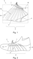
- Fig. 1 : shows an exemplary upper for a shoe, according to an embodiment of the present disclosure.
- Fig. 2 : shows an exemplary upper for a shoe, according to a further embodiment of the present disclosure.
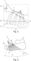
- Fig. 3 : shows an exemplary upper for a shoe, according to a further embodiment of the present disclosure.
- Fig. 4 : shows an exemplary schematic upper for a shoe, according to a further embodiment of the present disclosure.
- Fig. 5A : shows an exemplary schematic upper for a shoe, according to a further embodiment of the present disclosure.
- Fig. 5B : shows an exemplary schematic upper for a shoe, according to a further embodiment of the present disclosure.
- Fig. 5C : shows an exemplary schematic upper for a shoe, according to a further embodiment of the present disclosure.
- Fig. 5D : shows an exemplary schematic upper for a shoe, according to a further embodiment of the present disclosure.
- Fig. 5E : shows an exemplary schematic upper for a shoe, according to a further embodiment of the present disclosure.
- Fig. 5F : shows an exemplary schematic upper for a shoe, according to a further embodiment of the present disclosure.
- Fig. 6A : shows an exemplary knitting sequence to create a knitted portion comprising one or more knitted functional elements according to an embodiment of the present disclosure.
- Fig. 6B : shows an exemplary knitting sequence to create a knitted portion comprising one or more knitted functional elements according to a further embodiment of the present disclosure.
- Fig. 6C : shows an exemplary knitting sequence to create a knitted portion comprising one or more knitted functional elements according to a further embodiment of the present disclosure.
- Fig. 6D : shows an exemplary knitting sequence to create a knitted portion comprising one or more knitted functional elements according to a further embodiment of the present disclosure.
- Fig. 6E : shows an exemplary knitting sequence to create a knitted portion comprising one or more knitted functional elements according to a further embodiment of the present disclosure.
5. Detailed description of the preferred embodiments
-
In the following only some possible embodiments of the invention are described in detail. However, the present invention is not limited to these, and a multitude of other embodiments are applicable without departing from the scope of the invention. The presented embodiments can be modified in a number of ways and combined with each other whenever compatible and certain features may be omitted in so far as they appear dispensable. In particular, the disclosed embodiments may be modified by combining certain features of one embodiment with one or more features of another embodiment.
-
It is to be understood that not all features of the described aspects / embodiments have to be present for realizing the technical advantages provided by the present disclosure, which is defined by the subject-matter of the claims. The disclosed aspects / embodiments may be modified by combining certain features of one aspect / embodiment with one or more features of another aspect / embodiment. Specifically, the skilled person will understand that features, and / or functional elements of one aspect / embodiment can be combined with technically compatible features, and / or functional elements of any other aspect / embodiment of the present disclosure given that the resulting combination falls within the definition of the present disclosure.
-
While the embodiments below are described primarily with reference to an upper for a shoe, in particular a sports shoe, the skilled person will recognize that the disclosure according to the invention can equally be applied in a plurality of different technical fields and / or use cases.
-
Throughout the present figures and specification, the same reference numerals refer to the same elements. For the sake of clarity and conciseness, certain aspects of components or steps of certain embodiments are presented without undue detail where such detail would be apparent to those skilled in the art in light of the teachings herein and / or where such detail would obfuscate an understanding of more pertinent aspects of the embodiments.
-
As understood by the skilled person and / or in order to avoid redundancies, reference is also made to the explanations in the preceding sections, which also apply to the following detailed description. Further, not all features, parts, elements, aspects, components and / or steps are expressly indicated by reference signs for the sake of brevity and clarity. This particularly applies, where the skilled person recognizes that such features, parts, elements, aspects, components and / or steps are present in a plurality. One example of which may be the knitted functional elements.
Definitions
-
Unless otherwise stated, the term "substantial" or "substantially" as used in the present context may be understood to a great or significant extent or for the most part or essentially. In particular, manufacturing tolerances are included by this term.
-
The term "and / or" is only an association relationship describing associated objects and represents that three relationships may exist. For example, A and / or B may represent three conditions: i.e., independent existence of A, existence of both A and B and independent existence of B. In addition, the character "/" in the disclosure usually represents that previous and next associated objects form an "or" relationship.
-
For brevity, the one or more "knitted functional elements" are sometimes referred to herein as one or more "functional elements". In case not-knitted functional elements are meant, this is expressly indicated.
-
The term "bite line" as used in the present disclosure may refer to a line along the intersection of the upper and a shoe sole.
-
The term "course" as used in the present disclosure may refer to a predominantly horizontal row of needle loops (in an upright fabric as knitted) produced by adjacent needles during the same knitting cycle. In some instance, the term course may be used synonymously with the term row.
-
The term "wale" as used in the present disclosure may refer to a predominantly vertical column of intermeshed needle loops generally produced by the same needle knitting at successive (not necessarily all) knitting cycles. A wale may commence as soon as an empty needle starts to knit.
-
The term "tuck stitch" as used in the present disclosure may refer to a formation of a stitch when a needle already holding a stitch, receives a further stitch. This further stitch is tucked in behind the held stitch. Fabrics with tuck stitches may have a lower elasticity in the wale direction but an increased elasticity in the course direction. This may be the case, as the tuck stitches substantially pull down the held stitches and cause them to spread.
Description of figures
-
Fig. 1 shows an exemplary upper 2 for a shoe, according to an embodiment of the present disclosure.
-
The upper 2 comprises an inner layer 10 (not depicted in Fig. 1, but indicated in Fig. 3), arranged in proximity of a foot of a wearer, when the shoe is worn. The upper 2 also comprises an outer layer 30, arranged outside with respect to the inner layer 10, when the shoe is worn. The inner layer 10 comprises a knitted portion 20 (indicated in Fig. 1, however, the knitted portion 20 is covered by the outer layer 30 in Fig. 1), comprising one or more knitted functional elements 25 (indicated in Fig. 1, however, one or more knitted functional elements 25 are covered by the outer layer 30). The outer layer 30 at least partially covers the one or more knitted functional elements 25.
-
As can be gathered from Fig. 1, the one or more functional elements 25 are one or more elongate functional elements 25. In particular, the one or more functional elements 25 define one or more protrusions 25. The one or more protrusions 25 can extend from the inner layer 10 by at least 0.2 mm and /or by at most 8 mm. The one or more protrusions 25 have the shape of at least one of a rib, a ridge, a lamella, or a fin. This is to be understood such that each one of the one or more protrusions 25 taken on its own has such a shape. Individual ones of the one or more protrusions 25 may of course have a different shape. In other words, not all of the one or more protrusions 25 may be required to have the same shape.
-
The one or more functional elements 25 of Fig. 1 are arranged on a side of the inner layer 10 facing away from a foot of a wearer, when the shoe is worn. Thus, the one or more functional elements 25 are substantially sandwiched between the inner layer 10 and the outer layer 30. As can be seen in Fig. 1, the one or more functional elements 25 are discretely arranged on the inner layer 10 and between the outer layer 20 and the inner layer 10.
-
Alternatively or additionally, the one or more functional elements 25 can be arranged on a side of the inner layer 10 facing a foot of a wearer, when the shoe is worn.
-
The knitted portion 20 (the knitted portion 20 is covered by the outer layer 30 in Fig. 1) is located at a midfoot region 8 of the upper 2, in particular a region spanning from an instep region 7 to a sole region 8 of the upper 2. As can be seen in Fig. 1, the knitted portion 20 and the one or more functional elements 25 end at the sole region 8, which is arranged close to the bite line of the upper 2.
-
Moreover, each of the one or more functional elements 25 has an elongate axis, directed substantially from an instep region 7 towards a medial side region 5 (as best seen in Fig. 4) and / or lateral side 6 region of the upper 2.
-
Further, the one or more functional elements 25 are spaced apart from one another by at least 1 mm and /or by at most 50 mm.
-
Further still, the inner layer 10 comprises a further portion 40 (indicated in Fig. 1, however, the further portion 40 is covered by the outer layer 30 in Fig. 1), preferably a further knitted portion 40. The further portion 40 does not comprise a functional element. Moreover, the knitted portion 20 and the further portion 40 preferably encompass the whole inner layer 10.
-
Further, the one or more functional elements 25 are configured to bulge out the outer layer 30 of the upper 2 at least partially. This can be seen in Fig. 1 by way of the protrusions having an elongate and rib-like shape. Thereby, the one or more functional elements 25 are indirectly visible attributable to the three-dimensional elevation.
-
As also shown in Fig. 1, the one or more functional elements 25 can extend over the overall length of a course of the knitted portion 30. In Fig. 1, the course may be arranged so as to pass through an instep region 7 and a lateral side region 6 in proximity of a sole region 8 (i.e., close to a bite line of the upper 2) of the upper 2. Likewise, the course may be arranged so as to pass through an instep region 7 and a medial side region 5 of the upper 2. Of course, the course could also pass through an instep region 7 and a medial side region 5 and a lateral side region 6 of the upper 2.
-
As understood, the extension, location, and / or arrangement of the one or more functional elements 25 depends on the use case of the shoe as different requirements pertain. Different advantages can be achieved depending on the extension, location, and / or arrangement of the one or more functional elements 25. These different advantages are for instance highlighted by way of the different requirements for running (twisting in the midfoot region should be prevented and stability should be provided) and tennis (e.g., abrasion resistance and / or durability on a medial side region should be provided, as the shoe may slide) as described.
-
The one or more functional elements 25 may comprise one or more sections (as best seen in the knitting sequence in Fig. 6E), each section extending over a length of a course of the knitted portion 20 of at least 10% and / or of at most 80% of the overall length of the course of the knitted portion 20. As mentioned before, the course of the knitted portion 20 could be arranged so as to pass through an instep region 7 and a medial side region 5 (as best seen in Fig. 4) and / or lateral side region 7 in proximity of a sole region 8 (i.e., close to a bite line of the upper 2) of the upper 2.
-
The one or more functional elements 25 can be knitted integrally with the knitted portion 20. This can significantly reduce manufacturing costs, as substantially no separate parts, such as reinforcements elements, foam, laces, and / or the like would need to be provided.
-
As further shown in Fig. 1, the outer layer 30 covers substantially all of the one or more functional elements 25 of the knitted portion 20. Further, the outer layer 30 can cover the inner layer 10.
-
As shown in Fig. 1, the outer layer 30 may not comprise a knitted functional element 25 as the ones that the knitted portion 20 of the inner layer 10 comprises. This may be the case, since sufficient stability, stretching and / or any kind of functional property could already be provided by way of the inner layer 10.
-
As additionally derivable from the knitting sequences described further below, the one or more functional elements 25 may each define a substantially closed shape.
-
It is noted, that whenever a part, feature, layer, element and / or the like is described as being "knitted" or "knit" in the present disclosure, this may allow to derive the distinctive characteristic that it is formed of interlocking yarn or thread loops. These thread loops are also referred to as stitches and can be formed of one or several yarns or threads. Compared to other types of fabric, such as for example woven fabric, knitted fabric may have the advantage of comprising a certain level of stretchability so that the shoe upper may optimally adjust to the shape of the foot and provides the wearer with the necessary support.
-
Fig. 2 shows an exemplary upper 2 for a shoe, according to a further embodiment of the present disclosure. Fig. 3 shows an exemplary upper 2 for a shoe, according to a further embodiment of the present disclosure. These embodiments are similar to all other embodiments described herein and they can comprise one or more of the features described in the context of the other embodiments. Merely additional features are described for brevity.
-
One or more foils 31 are applied to the outer layer 30 in Fig. 2. This provides for reinforcement, waterproofing, and / or the like. As can be gathered from Fig. 2, the one or more foils 31 smoothly align with the outer layer 30 and these foils 31 do not substantially affect an embossed structure provided by the one or more functional elements 25 bulging out the outer layer 30. Thereby, the one or more functional elements 25 substantially maintain their shape and can still impart their beneficial functional properties to the upper.
-
As shown in Fig. 3, the outer layer 30 may alternatively or additionally comprise fusible yarns. After heat treatment such yarns may fuse to form a film-like surface 31 on the outer layer 30. Also in this example, the one or more functional elements 25 on the inner layer 10 can still be sensed by way of the embossing effect provided on the film-like surface 31 of the outer layer 30.
-
Fig. 4 shows an exemplary schematic upper 2 for a shoe, according to a further embodiment of the present disclosure. This embodiment is similar to and applicable to all other embodiments described herein and merely additional features are described for brevity.
-
As can be seen, the one or more functional elements 25 define the shape of a fan on a medial side region 5 of the upper 2. It is well encompassed, that the one or more functional elements 25 define the shape of a fan on the lateral side region 6 of the upper 2 (as indicated for instance in Fig. 1, Fig. 2, and Fig. 3). It is also possible that the one or more functional elements 25 define two fans separate from one another, for instance, one on the medial side region 5 of the upper 2 and one on the lateral side region 6 of the upper 2.
-
Further still, each of the one or more functional elements 25 is arranged at an angle α with respect to a neighboring functional element 25. This is exemplarily indicated by way of the two dashed lines placed onto the two functional elements 25 on the right-hand side of Fig. 4.
-
Further, as also shown in Fig. 4, the one or more functional elements 25 defining said shape of a fan may be arranged in a substantially circular segment around a central hub. The circular segment may have any angular segment with an angle β of any suitable size. For instance, the circular segment may have an angular segment with an angle β from about 0 to 180° as described elsewhere herein. The angle β is exemplarily indicated in Fig. 4 by way of the two dashed lines placed onto the knitted functional element 25 on the right most side and the knitted functional element 25 on the left most side. The substantially circular segment of the shape of the fan may have an angular segment with an angle β ranging from 10° to 160°, more preferably from 20° to 140°, more preferably from 30° to 130°, more preferably from 40° to 120°, more preferably from 50° to 110°, more preferably from 60° to 100°, most preferably from 70° to 95°. In the particular example if Fig. 4, the angle may be about 85° to 87°, in particular 86°. However, as understood, any kind of angle β may be encompassed by the present disclosure and the angle β is not to be limited to the example of Fig. 4, which just serves to illustrate the angle β.
-
The one or more functional elements 25 may be configured to allow the upper 2 to be stretched in a first direction X (as exemplarily indicated in Fig. 4 by way of the dotted line of the fourth knitted functional element 25 as seen from the left). Such a stretching of the upper 2 in a first direction X may be provided up to a threshold, beyond which the one or more functional elements 25 are configured to counteract further stretching of the stretched upper 2 in the first direction X. Further, the one or more functional elements 25 can be configured to allow the upper 2 to be stretched in a second direction Y (as exemplarily indicated in Fig. 4 by way of the dash-dotted line of the fourth knitted functional element 25 as seen from the left) different than the first direction X by an amount less than stretching in the first direction X up to the threshold. Preferably, the one or more functional elements 25 are configured to counteract stretching of the upper 2 in the second direction Y. The first direction X may be substantially parallel to the direction of a course of the knitted portion 10, and the second direction Y may be substantially parallel to the direction of a wale of the knitted portion 10.
-
It is noted that the knitted portion 20 may comprise any number of functional elements 25. For instance, the knitted portion 20 may comprise at least 1, 2, 3, 4, 5, 6, 7, 8, 9, 10 or more functional elements, and / or at most 50, 40, 30, 20, 15, 10 or less functional elements 25.
-
As noted elsewhere herein, the size of the knitted portion 20 may not be particularly relevant for the advantages of the one or more knitted functional elements 25 described herein to be applicable. The knitted portion 20 may occupy substantially the whole inner layer 10. In other examples, the knitted portion 20 may occupy a portion that is at most 95%, preferably at most 90%, more preferably at most 80%, more preferably at most 70%, more preferably at most 60%, more preferably at most 50%, more preferably at most 40% of the whole inner layer 10, and / or the knitted portion 20 may occupy a portion that is at least 5%, preferably at least 10%, more preferably at least 20%, more preferably at least 30%, more preferably at least 40% of the whole inner layer 10.
-
Fig. 5A , Fig. 5B , Fig. 5C , Fig. 5D , Fig. 5E , and Fig. 5F show exemplary schematic uppers 2 for a shoe, according to further embodiments of the present disclosure. The depicted embodiments are similar to and applicable to all other embodiments described herein and not all features of the foregoing embodiments are repeated for brevity only. Further, when a region of an upper 2, such as a medial side region 5 of the upper 2, a lateral side region 6 of the upper 2, an instep region 7 of the upper 2, and / or a midfoot region 8 of the upper 2 is described as comprising the one or more functional elements 25, it may well be the case that also another region of the upper 2 may additionally or alternatively comprise these one or more functional elements 25. Moreover, not all functional elements 25 are indicated by reference signs for brevity only.
-
Fig. 5A is an embodiment of an upper 2 shown in three different perspectives. The upper 2 shown in Fig. 5A may be particularly useful when used in athletic activities like tennis and / or similar athletic activities in which similar impacts are to be expected.
-
The picture at the top of Fig. 5A shows the upper 2 from a lateral side 6 view. The picture in the middle of Fig. 5A shows the upper 2 from a top view. The picture at the bottom of Fig. 5A shows the upper 2 from a medial side 5 view. The upper 2 comprises an inner layer (not shown), comprising a knitted portion 20 (not shown), comprising one or more knitted functional elements 25. In the picture at the top of Fig. 5A, the one or more knitted functional elements 25 are shown to be arranged in a toe region 4, and a lateral side region 6. The one or more knitted functional elements 25 are not arranged in a heel region 30. Further, the one or more knitted functional elements 25 are not arranged in an instep region 7 of the upper 2 and / or the one or more knitted functional elements 25 may not extend to the instep region 7 of the upper. As can be seen from the picture in the middle of Fig. 5A, the one or more knitted functional elements 25 are arranged in a toe region 4, a medial side region 5, and a lateral side region 6 of the upper 2. As can be seen from the picture at the bottom of Fig. 5A, the one or more knitted functional elements 25 are arranged in a toe region 4, a medial side region 5, and the one or more knitted functional elements 25 extend towards a heel region 30. In addition, the one or more knitted functional elements 25 extend towards the instep region 7 of the upper 2. Thus, the one or more knitted functional elements 25 substantially cover an overall medial side region 5 of the upper 2.
-
As shown in Fig. 5A, the one or more functional elements 25 are majorly located on the medial side region 5 so as to provide abrasion resistance and / or durability. This could be of importance, for instance, when the shoe is subject to sliding movements. This may be desired for tennis and / or athletic activities in which similar impacts are to be expected.
-
As shown in Fig. 5A, the one or more knitted functional elements 25 are arranged in a substantially continuous manner. Further, the one or more knitted functional elements 25 may be arranged substantially equidistantly with respect to one another. However, it is also possible to arrange the one or more knitted functional elements 25 in one or more groups, wherein at least one of the one or more groups comprises one or more knitted functional elements 25 that are substantially discontinuous. Further, any two of the knitted functional elements 25 may be provided with a space different than a space between two other knitted functional elements 25. Further, a spacing may be provided between the one or more groups. It is understood that in such a spacing, no knitted functional elements 25 may be provided (as shown in Fig. 5C, Fig. 5D, and Fig. 5E).
-
In the embodiment of Fig. 5A, high resistance yarns as described elsewhere herein are employed for knitting the knitted functional elements 25. This has the advantage that abrasion-resistance functional elements 25 can be provided, which can reduce wear, caused by the external environment. Non-exhaustive examples of useful sports applications of such an upper 2 may be tennis, badminton, basketball, handball, fencing or the like. In particular, slide and / or drag zones may be provided on the upper 2, which could protect the foot 1 (depicted in Fig. 5F) of a wearer without locking the foot movement. Further, the upper 2 may be prevented from wearing out when in intense contact with a court surface or an opponent in an athletic activity.
-
Fig. 5B is an embodiment of an upper 2 shown in three different perspectives. The upper 2 shown in Fig. 5B may be particularly useful when used in athletic activities like basketball and / or similar athletic activities in which similar impacts are to be expected.
-
The picture at the top of Fig. 5B shows the upper 2 from a lateral side 6 view. The picture in the middle of Fig. 5B shows the upper 2 from a top view. The picture at the bottom of Fig. 5B shows the upper 2 from a medial side 5 view. The embodiment of Fig. 5B is similar to the one of Fig. 5A and merely differences are described. As can be seen, the one or more knitted functional elements 25 are arranged in a toe region 4, in a medial side region 5, and in a lateral side region 6. Compared to Fig. 5A, the one or more knitted functional elements 25 are arranged on both, i.e., the medial side region 5, and the lateral side region 6 almost up to the heel region 30 of the upper 2. As can be seen in the picture of the middle of Fig. 5B, the one or more knitted functional elements 25 are substantially symmetrically with respect to a vertical plane arranged parallel to a heel 30 to toe 4 axis of the upper 2.
-
Fig. 5C shows two different embodiments of an upper 2. One embodiment is shown on the left side of Fig. 5C in two pictures and another embodiment is shown on the right side of Fig. 5C in two pictures. The top picture in each of the two embodiments shows the upper 2 in a status of maximum expansion. The bottom picture in each of the two embodiments shows the upper 2 in a status of maximum compression. This is indicated by the dashed lines in the bottom picture of each of the two embodiments, which resembles the shape of the upper 2 before compression.
-
In each embodiment, the upper 2 comprises an inner layer (not shown), comprising a knitted portion 20 (not shown), comprising one or more knitted functional elements 25. In each embodiment of Fig. 5C, the one or more knitted functional elements 25 are shown to be arranged in a region at least from an instep region 7 to a sole region of the upper 2. Further, as shown in the embodiment on the right side of Fig. 5C, the one or more functional elements 25 are arranged in a first group in a midfoot region of the upper 2. In addition, the one or more functional elements 25 are arranged in a second group in a region from the heel 30 towards a region in proximity of the Achilles tendon.
-
The first group and the second group, or generally any groups described herein, may in combination provide for additional functional enhancements. For instance, the groups may form a network of one or more knitted functional elements 25 that work in tandem to provide a desired effect and / or functionality. For instance, the groups may be provided with a line of interaction in between the groups, which could aid in achieving additional functionality. For instance, the line of interaction could be provided with more rigidity or with more elasticity. Thus, the groups may in combination contribute to a greater functionality as the sum of each individual group alone.
-
As shown in the embodiment on the left side of Fig. 5C, the one or more knitted functional elements 25 are arranged at least in a region from an instep region 7 to a sole region of the upper 2 (same as with the embodiment on the right side of Fig. 5C). Thereby, the one or more knitted functional elements 25 may be distributed substantially on the midfoot region of the upper 2. It is noted that with such an arrangement of the one or more knitted functional elements 25 in both embodiments of Fig. 5C, a good balance between two conflicting requirements can be struck: On the one side, sufficient freedom of movement of the forefoot region with respect to the rearfoot region of the upper 2 can be achieved. This also facilitate torsion-ability of the upper 2. On the other side, sufficient restriction of movement and / or stabilization of the midfoot region of the upper 2 can be achieved.
-
In the embodiment of Fig. 5C, elastic yarns as described elsewhere herein are employed for knitting the knitted functional elements 25. This has the advantage that a tight, form-fitting upper can be provided. This may be particularly useful when combined with a laceless construction. A further advantage is that the foot can be secured during dynamic movements. Non-exhaustive examples of useful sports applications of such an upper 2 may be football, rugby, running, training or the like. An additional advantage is that the upper 2 can offer a compression fit and that it is suitable for sports activities that involve prolonged durations.
-
Fig. 5D is an embodiment of an upper 2 shown in three different perspectives. The picture at the top of Fig. 5D shows the upper 2 from a medial side 5 view. The picture in the middle of Fig. 5D shows the upper 2 from a top view. The picture at the bottom of Fig. 5D shows the upper 2 from a lateral side 6 view.
-
The upper 2 comprises an inner layer (not shown), comprising a knitted portion 20 (not shown), comprising one or more knitted functional elements 25. As can be seen, the one or more knitted functional elements 25 may be provided at different regions of the upper 2. As derivable particularly from the picture in the middle of Fig. 5D, two groups of one or more knitted functional elements 25 pertain. One group of one or more knitted functional elements 25 is arranged in an instep region 7 of the upper 2. Another group of one or more knitted functional elements 25 arranged in a region in proximity of the Achilles tendon. The heel region 30 in proximity to a sole of the upper 2 may be free from one or more knitted functional elements 25.
-
In the embodiment of Fig. 5D, puffy yarns as described elsewhere herein are employed for knitting the knitted functional elements 25. This has the advantage that a volume of the functional elements 25 can be increased. This may offer comfortable padding in the collar and u-throat region of the upper 2. This may alleviate lace pressure for instance. Non-exhaustive examples of useful sports applications of such an upper 2 may be any kind of court sports. Instead of using a complete foam padding piece, incorporation of puffy yarns may allow for sweat absorption and faster drying, reducing the shoe's additional weight when being saturated. This may be useful for any sport, such as tennis, in particular when exposed to harsh weather conditions (e.g., high temperature, humidity or the like). Further, the upper 2 may have the advantage that it can provide for insulation for outdoor activities.
-
Fig. 5E is an embodiment of an upper 2 shown in three different perspectives. The picture at the top of Fig. 5E shows the upper 2 from a medial side 5 view. The picture in the middle of Fig. 5E shows the upper 2 from a top view. The picture at the bottom of Fig. 5E shows the upper 2 from a lateral side 5 view. The embodiment of Fig. 5E is similar to the one of Fig. 5D and merely differences are described. As can be seen, the one or more knitted functional elements 25 are arranged in an instep region 7 similar to the embodiment of Fig. 5D. The one or more knitted functional elements 25 may be arranged in a first group that is arranged in the instep region 7 of the upper 2. This first group may have a pointed shape as seen from a heel region 30 to a toe region 4 of the upper 2. Further, one or more knitted functional elements 25 may be arranged in a second group that is arranged in an ankle region 3 of the upper 2.
-
Fig. 5F is an embodiment of an upper 2, shown in one perspective in the middle part on the right-hand side. Further, the bottom picture and the two top pictures of Fig. 5F depict an arrangement of one or more functional elements 25 relative to a foot 1 of a wearer in three different perspectives. The upper 2 comprises an inner layer (not shown), comprising a knitted portion 20 (not shown), comprising one or more knitted functional elements 25. As can be seen, the one or more knitted functional elements 25 are arranged in at least one overall side region of the upper 2. Further, the one or more knitted functional elements 25 enclose a sole region of the upper 2, as indicated in the bottom picture and the two top pictures of Fig. 5F. In the embodiment of Fig. 5F, fusible yarns as described elsewhere herein are employed for knitting the knitted functional elements 25. This has the advantage that a quite resilient yarn is used that exhibits reduced or almost no stretching. This provides for stability, which is useful for many sports applications, for instance sports applications involving side cuts. The upper 2 offers a secure containment for the foot 1. This improves stability, which is particularly useful for court sports as well as various other sports applications, such as fencing, wrestling, and / or training.
-
In any one of the embodiments described herein, the upper 2 can be made on a flat knitting machine or a circular knitting machine. A differentiation can be made between flat knitting and circular knitting machines. In flat knitting machines, a thread feeder feeds the thread back and forth along a row of needles. In a circular knitting machine, the needles are arranged in a circular manner and the thread feeding correspondingly takes place in a circular movement along one or more round rows (also referred to herein as courses) of needles which may be positioned on a cylinder.
-
Employing a small circular knitting machine has the advantage that most or all of the upper 2 for a shoe may directly be made with the correct size and shape so that no further cutting step is needed. However, as described elsewhere herein, it is also possible to produce the upper 2 on a flat knitting machine or a large circular knitting machine. When employing a large circular knitting machine, the upper 2 may be cut out from a tubular textile after said textile has been produced by said machine.
-
It is noted that small circular knitting machines may differ from large circular knitting machines by their size, capacity and /or type of products they produce. The skilled person may readily distinguish a small circular knitting machine from a large circular knitting machine.
-
Small circular knitting machines are typically compact and have a smaller diameter compared to large circular knitting machines. Such small circular knitting machines may be useful for producing tubular fabrics such as socks, gloves, hats, or the like. Large circular knitting machines may be larger in size and may be used to produce wide fabrics. In some examples, large circular knitting machines can have a greater number of needles. This facilitates the production of wider fabrics.
-
It is noted that the inner layer 10 and / or the outer layer 30 may comprise a single layer fabric or a double layer fabric. The double layer fabric may be achieved by using a double bed knitting machine. This machine has two needle beds, allowing for the simultaneous knitting of two layers of fabric. The layers of the double layer fabric may be interconnected through certain stitch patterns, creating a stable and coherent fabric with no visible seams on either side. Such double layer fabric may be provided by flat knitting machines as well as by circular knitting machines. When looked at the double layer fabric from the side, the needles of the two rows of needles may, for example, be opposite each other at a substantially right angle. This may enable the manufacture of more elaborate structures or fabrics. The use of two rows of needles may allow to manufacture a one-layered or a two-layered weft knitted fabric.
-
In the embodiments described herein, manufacturing of the upper 2 (in particular manufacturing of the upper 2 after knitting of the inner layer 10 (indicated in Fig 3) and the outer layer 30) may be as follows: The outer layer 30 is put over the inner layer 10. Alternatively, the inner layer 10 is inserted into the outer layer 30. Subsequently, both layers are joined at their respective free ends. Such joining may be performed for example by linking, sewing, welding, or gluing. The outer layer 30 and the inner layer 10 may have the shape of an elongate hollow knit structure, such as a cylinder, after knitting. Thereby, they may comprise openings at their respective free ends which are also closed by joining the free ends. The openings are preferably joined in a longitudinal direction on the bottom of the layers 10, 30, so that the seam that joins the free ends may be completely hidden by a sole of the shoe. Thereby, by virtue of said joining, the free ends may not be recognized as "free ends" anymore after joining.
-
Fig. 6A shows an exemplary knitting sequence to create a knitted portion 20 comprising one or more knitted functional elements 25 according to an embodiment of the present disclosure. This knitting sequence is applicable to all other embodiments described herein and may be employed additionally or alternatively to any other knitting sequence described herein. Fig. 6A also shoes the course direction C and the wale direction W, which applies also to Fig. 6B, Fig. 6C, Fig. 6D, and Fig. 6E.
-
As generally described herein, the one or more functional elements 25 can be formed by stitches 22a, 22b, 22c, 22d, 22e, 22f, 22g, 22h (summarized as 22a - 22h) that are different than the stitches 21a, 21b (exemplarily only two of these are indicated in Fig. 6A) of the remaining part of the knitted portion 20. Preferably, the one or more functional elements 25 are formed by tuck stitches 22a - 22h.
-
The one or more functional elements 25 can be formed by tuck stitches 22a - 22h comprising at least one, preferably at least two, preferably at least three, preferably at least four, preferably at least five, preferably at least six, preferably at least seven, preferably at least eight courses of stitches, and / or at most 25, preferably at most 20, preferably at most 18, preferably at most 16, preferably at most 15 courses of stitches. In Fig. 6A, a first set 22 comprising 8 courses of tuck stitches 22a - 22h and a second set 22' comprising 8 courses of tuck stitches 22a - 22h is indicated. The first set 22 and the second set 22' in combination form one knitted functional element 25.
-
Increasing the number of courses of tuck stitches may cause the height of a functional element 25 to be increased. Further, also the stiffness provided by the functional element 25 can be increased. In addition, having a greater number of courses of tuck stitches there will be more material gathered. This is helpful for creating the shapes of the one or more functional elements 25 and imparting functional properties thereby.
-
The course of normal stitches 21b may reduce the strain and / or tension on the needles of the knitting machine. Thereby, this may prevent the needles from breaking. In addition, this may relax the knit structure. This is particularly helpful between two sets of 22, 22' of courses of tuck stitches. However, as shown in Fig. 1, this could also be employed at the border of a set 22 as indicated in Fig. 6A by way of the course of normal stitches 21a.
-
Fig. 6B shows an exemplary knitting sequence to create a knitted portion 20 comprising one or more knitted functional elements 25 according to a further embodiment of the present disclosure. This knitting sequence is applicable to all other embodiments described herein and may be employed additionally or alternatively to any other knitting sequence described herein.
-
According to the knitting sequence of Fig. 6B, a functional element 25 comprises four sets 22, 22', 22", 22‴, each comprising four courses of tuck stitches 22a, 22b, 22c, 22d, are indicated. Each of the four sets 22, 22', 22", 22‴ is separated from a neighboring set by a course of normal stitches 21b, 21c, 21d. The same advantages as laid out in Fig. 6A with respect to the course of normal stitches 21b apply to the course of normal stitches 21b, 21c, 21d in Fig. 6B.
-
This knitting sequence provides an increased width of the functional element 25, as multiple sets of courses of tuck stitches are provided. This will create an enlarged area of the surface of the functional element 25. Thereby, the top surface of the functional element 25 can be made wider. In turn, this may increase the width of the functional element 25. This could be made broader than 1 cm for instance and as described elsewhere herein.
-
Fig. 6C shows an exemplary knitting sequence to create a knitted portion 20 comprising one or more knitted functional elements 25 according to a further embodiment of the present disclosure. This knitting sequence is applicable to all other embodiments described herein and may be employed additionally or alternatively to any other knitting sequence described herein.
-
According to the knitting sequence of Fig. 6C, the functional element 25 comprises two sets 22, 22', each comprising four courses of tuck stitches 22a, 22b, 22c, 22d. Each of the two sets 22, 22' is separated from a neighboring set 22, 22' by a course of normal stitches 21b. The same advantages as laid out in Fig. 6A with respect to the course of normal stitches 21b apply to the course of normal stitches 21b in Fig. 6D.
-
In Fig. 6C, the placement of the course of tuck stitches of the first set 22 and of the second set 22' has been altered relative to one another so as to achieve a special visual effect. In particular, small discrete portions of functional elements 25 are provided in the course direction C. These discrete portions of the functional elements 25 are separated by a gap (indicated by letter "g" in Fig. 6C) and / or an interruption in the wale direction W.
-
This may contribute to the overall appearance of the functional element 25. Thereby, different visual effects can be achieved by the functional element 25.
-
Fig. 6D shows an exemplary knitting sequence to create a knitted portion 20 comprising one or more knitted functional elements 25 according to a further embodiment of the present disclosure. This knitting sequence is applicable to all other embodiments described herein and may be employed additionally or alternatively to any other knitting sequence described herein.
-
According to the knitting sequence of Fig. 6D, the functional element 25 comprises two sets 22, 22', each comprising four courses of tuck stitches 22a, 22b, 22c, 22d. Each of the two sets 22, 22' is separated from a neighboring set 22, 22' by a course of normal stitches 21b. The same advantages as laid out in Fig. 6A with respect to the course of normal stitches 21b apply to the course of normal stitches 21b in Fig. 6D.
-
Each of the two sets 22, 22' spans the entire width of the fabric. This may represent a long uninterrupted functional element 25. In other words, the functional element 25 extends over the overall length of a course of the knitted portion 20.
-
Fig. 6E shows an exemplary knitting sequence to create a knitted portion 20 comprising one or more knitted functional elements 25 according to a further embodiment of the present disclosure. This knitting sequence is applicable to all other embodiments described herein and may be employed additionally or alternatively to any other knitting sequence described herein.
-
According to the knitting sequence of Fig. 6E, the functional element 25 comprises several sections. Each section comprises two sets 22, 22', each comprising four courses of tuck stitches 22a, 22b, 22c, 22d (for clarity reasons only, the courses of tuck stitches are not provided with reference signs, but they are apparent to the skilled person when consulting any one of the foregoing figures). Each of the two sets 22, 22' of each section is separated from a neighboring set 22, 22' by a course of normal stitches 21b. The same advantages as laid out in Fig. 6A with respect to the course of normal stitches 21a apply to the course of normal stitches 21b in Fig. 6D.
-
The several sections are arranged in a staggered manner. This may allow to impart the functional properties according to the desired needs of the use case of the shoe.
-
Although the description of Fig. 6A to 6E relates, in part, to one functional element 25, the same features and advantages applies to any one of the remaining one of the one or more functional elements 25.
-
In any one of the embodiments described herein, the one or more functional elements 25 can comprise one or more of an elastic yarn, a fusible yarn, in particular a low-melt temperature fusible yarn, a polyester yarn, a puffy yarn, a silicon yarn. Some further exemplary types of yarns in line with the present disclosure and which can be used for the inner layer 10, the knitted portion 20, the one or more functional elements 25, the outer layer 30, and / or the further portion 40 of the inner layer 10 are the following: fusible yarn, in particular low-melt temperature fusible yarn, thermoplastic polyurethane (TPU) yarn, reflective yarn, water resistant/repellent yarn, waterproof yarn, high tenacity yarn, abrasion resistant yarn, durable yarn, shrink yarn, recycled yarn, natural fiber yarn (e.g. wool and cotton), hybrid yarn, anti-microbial (anti-bacterial) yarn like copper, zinc, silver, elastic yarn, UV resistant yarn, bio-based yarn, textured yarn, cellulose yarn, regenerated yarn, such as cupro and modal yarns that are high-strength cellulose fiber yarns, and / or a monofilament yarn.
-
The yarns according to the present disclosure can comprise natural fibers, synthetic fibers, and / or blends. The yarn can be spun from natural fibers such as cotton, wool, silk, linen, hemp, and jute. Each type of natural fiber may bring its own unique characteristics to the yarn, resulting in fabrics with different textures, softness, warmth, and breathability. The yarn can also be made from synthetic fibers like polyester, nylon, acrylic, and rayon. These fibers may be manufactured using chemical processes and can offer specific properties like durability, moisture-wicking abilities, and colorfastness. The yarn can be composed of a blend of different fibers, combining the desirable characteristics of each material. For example, a yarn might be a blend of cotton and polyester to achieve both softness and strength. The yarns according to the present disclosure have various thicknesses and / or weights, which are often categorized by the number of plies (strands) and the thickness of the individual fibers or filaments. The weight of the yarn may affect the drape, density, and appearance of the resulting fabric.
-
It is noted that the above embodiments and / or examples may be combined with further aspects as described herein and details of the embodiments and / or examples may also be omitted, as will be understood by the skilled person. The scope of protection is determined by the claims and is not limited by the embodiments and / or examples disclosed in the above figures.
6. Further embodiments
-
The invention is further described by the following embodiments:
- 1. An upper (2) for a shoe, the upper (2) comprising:
- an inner layer (10), arranged in proximity of a foot of a wearer, when the shoe is worn;
- an outer layer (30), arranged outside with respect to the inner layer (10), when the shoe is worn;
- wherein the inner layer (10) comprises a knitted portion (20), comprising one or more knitted functional elements (25),
- wherein the outer layer (30) at least partially covers the one or more knitted functional elements (25).
- 2. The upper (2) according to embodiment 1, wherein the one or more functional elements (25) are one or more elongate functional elements (25).
- 3. The upper (2) according to any one of the preceding embodiments, wherein the one or more functional elements (25) define one or more protrusions.
- 4. The upper (2) according to embodiment 3, wherein the one or more protrusions extend from the inner layer (10) by at least 0.2 mm, preferably at least 0.4 mm, preferably at least 0.6 mm, preferably at least 0.8 mm, preferably at least 1 mm, preferably at least 1.2 mm, preferably at least 1.4 mm, preferably at least 1.6 mm, preferably at least 1.8 mm, preferably at least 2 mm,
and /or by at most 8 mm, preferably at most 6 mm, preferably at most 5 mm, preferably at most 4 mm, preferably at most 3 mm, preferably at most 2.8 mm, preferably at most 2.5 mm. - 5. The upper (2) according to any one of embodiments 3 or 4, wherein the one or more protrusions have the shape of at least one of a rib, a ridge, a lamella, or a fin.
- 6. The upper (2) according to any one of the preceding embodiments, wherein the one or more functional elements (25) are arranged on a side of the inner layer (10) facing away from a foot of a wearer, when the shoe is worn, such that the one or more functional elements (25) are substantially sandwiched between the inner layer (10) and the outer layer (30).
- 7. The upper (2) according to any one of the preceding embodiments, wherein the one or more functional elements (25) are arranged on a side of the inner layer (10) facing a foot of a wearer, when the shoe is worn.
- 8. The upper (2) according to any one of the preceding embodiments, wherein the one or more functional elements (25) define the shape of a fan on at least one of a lateral side region (6) and a medial side region (5) of the upper (2).
- 9. The upper (2) according to any one of the preceding embodiments, wherein each of the one or more functional elements (25) is arranged at an angle (a) with respect to a neighboring functional element (25).
- 10. The upper (2) according to any one of the preceding embodiments, wherein the knitted portion (20) is located at a midfoot region of the upper (2), in particular a region spanning from an instep region (7) to a sole region (9) of the upper (2).
- 11. The upper (2) according to any one of the preceding embodiments, wherein each of the one or more functional elements (25) has an elongate axis, directed substantially from an instep region (7) towards a medial side region (5) and/or lateral side region (6) of the upper (2).
- 12. The upper (2) according to any one of the preceding embodiments, wherein the one or more functional elements (25) are spaced apart from one another by at least 1 mm, preferably at least 2 mm, preferably at least 3 mm, preferably at least 5 mm, preferably at least 10 mm,
and /or by at most 50 mm, preferably at most 40 mm, preferably at most 30 mm, preferably at most 25 mm, preferably at most 20 mm, preferably at most 18 mm, preferably at most 15 mm. - 13. The upper (2) according to any one of the preceding embodiments, wherein the inner layer (10) comprises a further portion (40), preferably a further knitted portion (40), the further portion (40) not comprising a functional element (25),
wherein the knitted portion (20) and the further portion (40) preferably encompass the whole inner layer (10). - 14. The upper (2) according to any one of the preceding embodiments, wherein the one or more functional elements (25) are configured to allow the upper (2) to be stretched in a first direction (X).
- 15. The upper (2) according to embodiment 14, wherein the one or more functional elements (25) are configured to allow the upper (2) to be stretched in the first direction (X) up to a threshold, beyond which the one or more functional elements (25) are configured to counteract further stretching of the stretched upper (2) in the first direction (X).
- 16. The upper (2) according to any one of embodiments 14 or 15, wherein the one or more functional elements (25) are configured to allow the upper (2) to be stretched in a second direction (Y) different than the first direction (X) by an amount less than stretching in the first direction (X) up to the threshold,
wherein the one or more functional elements (25) are preferably configured to counteract stretching of the upper (2) in the second direction (Y). - 17. The upper (2) according to any one of embodiments 14 to 16, wherein the first direction (X) is substantially parallel to the direction (C) of a course of the knitted portion (20),
wherein the second direction (Y) is preferably substantially parallel to the direction (W) of a wale of the knitted portion (20). - 18. The upper (2) according to any one of the preceding embodiments, wherein the one or more functional elements (25) are configured to bulge out the outer layer (30) at least partially.
- 19. The upper (2) according to any one of the preceding embodiments, wherein the one or more functional elements (25) extend over the overall length of a course of the knitted portion (20),
wherein the course is preferably arranged so as to pass through an instep region (7) and a medial side region (5) and / or lateral side region (6) in proximity of a sole region (9) of the upper (2). - 20. The upper (2) according to any one of the preceding embodiments, wherein the one or more functional elements (25) comprise one or more sections, each section extending over a length of a course of the knitted portion (20) of at least 10%, preferably at least 20%, preferably at least 30%, preferably at least 50%, and/or of at most 80%, preferably at most 70%, preferably at most 60% of the overall length of the course of the knitted portion (20),
wherein the course of the knitted portion (20) is preferably arranged so as to pass through an instep region (7) and a medial side region (5) and / or lateral side region (6) in proximity of a sole region (9) of the upper (2). - 21. The upper (2) according to any one of the preceding embodiments, wherein the one or more functional elements (25) are knitted integrally with the knitted portion (20).
- 22. The upper (2) according to any one of the preceding embodiments, wherein the one or more functional elements (25) are formed by stitches (22a, 22b, 22c, 22d, 22e, 22f, 22g, 22h) that are different than the stitches (21a, 21b, 21c, 21d) of the remaining part of the knitted portion (20),
wherein the one or more functional elements (25) are preferably formed by tuck stitches (22a, 22b, 22c, 22d, 22e, 22f, 22g, 22h). - 23. The upper (2) according to embodiment 22, wherein the one or more functional elements (25) are formed by tuck stitches (22a, 22b, 22c, 22d, 22e, 22f, 22g, 22h) comprising at least 1, preferably at least 2, preferably at least 3, preferably at least 4, preferably at least 5, preferably at least 6, preferably at least 7, preferably at least 8 courses of stitches (21a-d, 22a-h),
and/or at most 25, preferably at most 20, preferably at most 18, preferably at most 16, preferably at most 15 courses of stitches (21a-d, 22a-h). - 24. The upper (2) according to any one of the preceding embodiments, wherein the one or more functional elements (25) comprise one or more of an elastic yarn, a fusible yarn, in particular a low-melt temperature fusible yarn, a polyester yarn, a puffy yarn, a silicon yarn,
wherein the one or more functional elements (25) preferably consist of one or more of an elastic yarn, a fusible yarn, in particular a low-melt temperature fusible yarn, a polyester yarn, a puffy yarn, a silicon yarn. - 25. The upper (2) according to any one of the preceding embodiments, wherein the outer layer covers substantially all of the one or more functional elements (25) of the knitted portion (20),
wherein the outer layer (30) preferably covers the inner layer (10). - 26. The upper (2) according to any one of the preceding embodiments, wherein the outer layer (30) comprises one or more of a polyester yarn, a blended yarn, a fusible yarn, in particular a low-melt temperature fusible yarn, a monofilament yarn.
- 27. The upper (2) according to any one of the preceding embodiments, wherein the outer layer (30) does not comprise a functional element (25).
- 28. The upper (2) according to any one of the preceding embodiments, wherein the inner layer (10) and the outer layer (30) are connected to one another in a seamless manner,
preferably at a foot-receiving opening of the upper (2). - 29. The upper (2) according to any one of the preceding embodiments, wherein the inner layer (10) and the outer layer (30) form a two-layered assembly.
- 30. The upper (2) according to any one of the preceding embodiments, wherein the upper (2) is made on a flat knitting machine or on a circular knitting machine, preferably on a circular knitting machine.
- 31. The upper (2) according to any one of the preceding embodiments, wherein the one or more functional elements (25) each define a substantially closed shape.
- 32. A shoe, in particular a sports shoe, the shoe comprising:
- an upper (2) according to one of embodiments 1 to 31; and
- a sole attached to the upper (2).
7. List of reference signs used
-
- 1
- foot of a wearer
- 2
- upper
- 3
- ankle region of the upper
- 4
- toe region of the upper
- 5
- medial side region of the upper
- 6
- lateral side region of the upper
- 7
- instep region of the upper
- 8
- midfoot region of the upper
- 9
- sole region of the upper
- 10
- inner layer
- 20
- knitted portion of the inner layer
- 21a, 21b
- course of normal stiches
- 22, 22'
- set of tuck stitches
- 22a, 22b, 22c, 22d, 22e, 22f, 22g, 22h
- course of tuck stitches
- 25
- knitted functional element
- 30
- outer layer
- 31
- foil / film-like surface
- 40
- further portion of the inner layer
- α
- angle between two functional elements
- X
- first direction
- Y
- second direction
- C
- course direction
- W
- wale direction
- g
- gap in wale direction