EP4527224A1 - Aerosol generation device capable of controlling heating temperature - Google Patents
Aerosol generation device capable of controlling heating temperature Download PDFInfo
- Publication number
- EP4527224A1 EP4527224A1 EP23850244.7A EP23850244A EP4527224A1 EP 4527224 A1 EP4527224 A1 EP 4527224A1 EP 23850244 A EP23850244 A EP 23850244A EP 4527224 A1 EP4527224 A1 EP 4527224A1
- Authority
- EP
- European Patent Office
- Prior art keywords
- temperature
- heating
- heating unit
- unit
- aerosol generation
- Prior art date
- Legal status (The legal status is an assumption and is not a legal conclusion. Google has not performed a legal analysis and makes no representation as to the accuracy of the status listed.)
- Pending
Links
Images
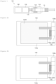


Classifications
-
- A—HUMAN NECESSITIES
- A24—TOBACCO; CIGARS; CIGARETTES; SIMULATED SMOKING DEVICES; SMOKERS' REQUISITES
- A24F—SMOKERS' REQUISITES; MATCH BOXES; SIMULATED SMOKING DEVICES
- A24F40/00—Electrically operated smoking devices; Component parts thereof; Manufacture thereof; Maintenance or testing thereof; Charging means specially adapted therefor
- A24F40/50—Control or monitoring
- A24F40/57—Temperature control
-
- A—HUMAN NECESSITIES
- A24—TOBACCO; CIGARS; CIGARETTES; SIMULATED SMOKING DEVICES; SMOKERS' REQUISITES
- A24F—SMOKERS' REQUISITES; MATCH BOXES; SIMULATED SMOKING DEVICES
- A24F40/00—Electrically operated smoking devices; Component parts thereof; Manufacture thereof; Maintenance or testing thereof; Charging means specially adapted therefor
- A24F40/40—Constructional details, e.g. connection of cartridges and battery parts
- A24F40/46—Shape or structure of electric heating means
-
- A—HUMAN NECESSITIES
- A24—TOBACCO; CIGARS; CIGARETTES; SIMULATED SMOKING DEVICES; SMOKERS' REQUISITES
- A24F—SMOKERS' REQUISITES; MATCH BOXES; SIMULATED SMOKING DEVICES
- A24F40/00—Electrically operated smoking devices; Component parts thereof; Manufacture thereof; Maintenance or testing thereof; Charging means specially adapted therefor
- A24F40/50—Control or monitoring
- A24F40/51—Arrangement of sensors
-
- A—HUMAN NECESSITIES
- A24—TOBACCO; CIGARS; CIGARETTES; SIMULATED SMOKING DEVICES; SMOKERS' REQUISITES
- A24F—SMOKERS' REQUISITES; MATCH BOXES; SIMULATED SMOKING DEVICES
- A24F40/00—Electrically operated smoking devices; Component parts thereof; Manufacture thereof; Maintenance or testing thereof; Charging means specially adapted therefor
- A24F40/50—Control or monitoring
- A24F40/53—Monitoring, e.g. fault detection
-
- A—HUMAN NECESSITIES
- A24—TOBACCO; CIGARS; CIGARETTES; SIMULATED SMOKING DEVICES; SMOKERS' REQUISITES
- A24F—SMOKERS' REQUISITES; MATCH BOXES; SIMULATED SMOKING DEVICES
- A24F40/00—Electrically operated smoking devices; Component parts thereof; Manufacture thereof; Maintenance or testing thereof; Charging means specially adapted therefor
- A24F40/60—Devices with integrated user interfaces
-
- G—PHYSICS
- G08—SIGNALLING
- G08B—SIGNALLING SYSTEMS, e.g. PERSONAL CALLING SYSTEMS; ORDER TELEGRAPHS; ALARM SYSTEMS
- G08B6/00—Tactile signalling systems, e.g. tactile personal calling systems
-
- A—HUMAN NECESSITIES
- A24—TOBACCO; CIGARS; CIGARETTES; SIMULATED SMOKING DEVICES; SMOKERS' REQUISITES
- A24F—SMOKERS' REQUISITES; MATCH BOXES; SIMULATED SMOKING DEVICES
- A24F40/00—Electrically operated smoking devices; Component parts thereof; Manufacture thereof; Maintenance or testing thereof; Charging means specially adapted therefor
- A24F40/20—Devices using solid inhalable precursors
Definitions
- the present invention relates to an aerosol generation device. More particularly, the present invention relates to an aerosol generation device capable of controlling heating temperature.
- the aerosol generation device may include a heating unit capable of controlling heating temperature inside the device.
- the heating unit may control the heating temperature for heating the aerosol generation article, or may control the heating temperature for heating the vaporizing unit.
- the heating unit may control the heating temperature inside the aerosol generation device according to user's preference using the aerosol generation device.
- the heating unit may control the heating temperature under various conditions depending on conditions inside the aerosol generation device.
- the vaporizing unit may include an aerosol generating material, and the heating unit may emit the aerosol generating material by applying heat to the aerosol generating material.
- the heating unit continues to heat in the vaporizing unit even when all the aerosol generating materials are consumed within the vaporizing unit, damage may occur to the heating unit disposed within the vaporizing unit.
- an object of the present invention to provide an aerosol generation device capable of controlling internal heating temperature based on stimulation detected by a sensor unit.
- an aerosol generation device capable of controlling heating temperature includes: an aerosol generation article insertion part into which an aerosol generation article is insertable and which includes a first heating unit that applies heat to the aerosol generation article; a vaporizing unit that includes an aerosol generating material, a second heating part applying heat to the aerosol generating material, and a temperature sensor confirming a temperature of the second heating part; and a control unit that controls the first heating unit and the second heating unit, respectively.
- control unit may heat only the first heating unit among the first heating unit and the second heating unit.
- the preset temperature may be 300°C.
- control unit may turn on the first heating unit when the temperature of the second heating unit increases above the preset temperature.
- the first temperature range may be 120°C to 200°C
- the second temperature range may be 150°C to 250°C.
- the aerosol generation device may further include a display unit that displays an image, wherein the control unit may operate the display unit when the temperature of the second heating unit increases above the preset temperature.
- control unit may lower the heating temperature of the second heating unit when the temperature of the second heating unit confirmed by the temperature sensor increases above a preset temperature.
- lowering the heating temperature of the second heating unit may turn off the second heating unit or lower the heating temperature heated by the second heating unit.
- control unit may increase the temperature of the first heating unit when the temperature of the second heating unit increases above the preset temperature, and increasing the heating temperature of the first heating unit may turn on the first heating unit or may further increase the heating temperature at which the first heating unit is heated.
- the aerosol generation device may include a first heating unit disposed in an aerosol generation article insertion part to heat an aerosol generation article, and a second heating unit disposed in a vaporizing unit to heat an aerosol generating material.
- the heating temperatures of the first heating unit and the second heating unit may be adjusted respectively, and determined dependently on each other depending on the remaining amount of aerosol generating material or the heating temperature range of the second heating unit, thereby preventing the damage to the aerosol generation device while maintaining the smoker's smoking satisfaction.
- an "aerosol generating material” means a material capable of generating an aerosol, and may also refer to an aerosol forming substrate.
- the aerosol may include a volatile compound.
- the aerosol generating material may be solid or liquid.
- the solid aerosol generating material may include a solid material based on tobacco raw materials such as planar leaf tobacco, cut filler, and reconstituted tobacco
- the liquid aerosol generating material may include liquid materials based on nicotine, tobacco extracts, and various flavoring agents.
- tobacco raw materials such as planar leaf tobacco, cut filler, and reconstituted tobacco
- liquid aerosol generating material may include liquid materials based on nicotine, tobacco extracts, and various flavoring agents.
- tobacco raw materials such as planar leaf tobacco, cut filler, and reconstituted tobacco
- the liquid aerosol generating material may include liquid materials based on nicotine, tobacco extracts, and various flavoring agents.
- an aerosol generation device may be a device that generates an aerosol using an aerosol generating material to generate an aerosol that can be inhaled directly into a user's lung through a user's mouth.
- the aerosol generation device may be a holder.
- FIG. 1 is a diagram illustrating an embodiment of an aerosol generation device according to the present invention.
- an aerosol generation device 100 may include an aerosol generation article insertion part 110, a first heating unit 120, a vaporizing unit 130, a second heating unit 135, and a control unit 140.
- An aerosol generation article 10 may be inserted into the aerosol generation article insertion part 110.
- the aerosol generation device 100 only components related to the present embodiment are illustrated. Accordingly, those skilled in the art can easily understand that other general-purpose components in addition to the components illustrated in FIG. 1 may be further included in the aerosol generation device 100.
- the aerosol generation device 100 may be in the form of a stick or a holder.
- the aerosol generation article insertion part 110 corresponds to one area of the aerosol generation device 100 and may provide a space into which the aerosol generation article 10 is inserted.
- the aerosol generation article 10 may have a generally known form, and may have a form in which tobacco raw materials are deposited on a heat-conducting material.
- the heat-conducting material may be a metal foil, such as aluminum foil.
- the first heating unit 120 may heat the aerosol generation article 10 inserted into the aerosol generation article insertion part 110.
- the heating unit 120 may be, for example, a heater module.
- the heater module may include a tubular heating element, a plate-shaped heating element, and a needle-shaped or rod-shaped heating element, and may heat the inside and/or outside of the aerosol generation article 10 depending on the shape of the heating element.
- the first heating unit 120 may generate an aerosol with tobacco flavor by heating the aerosol generation article 10. Accordingly, a user may inhale an aerosol with tobacco flavor by inhaling one end of the aerosol generation article 10 with his/her mouth.
- the suction power with which the user inhales one end of the aerosol generation article 10 may be maintained within a certain range.
- the vaporizing unit 130 may be coupled to the aerosol generation device 100 so that it can be replaced.
- a second heating unit 135 may be disposed inside the vaporizing unit 130.
- the second heating unit 135 may be, for example, a heater module.
- the heater module may include a wick and a vaporizing unit, and the heater module may generate an aerosol by heating the aerosol generating material, which is absorbed through the wick, through the vaporizing unit.
- the vaporizing unit 130 may generate an aerosol by heating the aerosol generating material stored therein using the second heating unit 135, and the generated aerosol may be released toward the inserted aerosol generation article 10 so that the generated aerosol passes through the aerosol generation article 10 inserted into the aerosol generation article insertion part 110.
- the control unit 140 may control the overall operation of the aerosol generation device 100. Specifically, the control unit 140 may control the operations of the first heating unit 120, the vaporizing unit 130, and the second heating unit 135, as well as other components included in the aerosol generation device 100. In addition, the control unit 140 may confirm the state of each component of the aerosol generation device 100 and determine whether the aerosol generation device 100 is in an operable state.
- the aerosol generation device 100 may further include a battery, and the control unit 140 may check the charging state of the battery to determine whether the aerosol generation device 100 is in an operable state.
- the aerosol generation device 100 may further include a display unit and a vibration generation unit, and the control unit 140 may confirm the state of the aerosol generation device 100 to operate the display unit and/or the vibration generation unit.
- the control unit 140 may control the operation of components that may be included in the aerosol generation device 100.
- the control unit 140 may include at least one processor.
- the control unit may be implemented as an array of a plurality of logic gates or may be implemented as a combination of a general-purpose microprocessor and a memory in which a program executable in the microprocessor is stored.
- a general-purpose microprocessor and a memory in which a program executable in the microprocessor is stored.
- present embodiment may be implemented with other types of hardware.
- FIGS. 2A and 2B are diagrams illustrating an embodiment of the vaporizing unit included in the aerosol generation device of FIG. 1 .
- the vaporizing unit 130 may include a storage unit 130a, a temperature sensor 130b, and a second heating unit 135.
- the storage unit 130a may provide a space in which an aerosol generating material (AGM) is stored.
- the aerosol generating material (AGM) stored in the provided space may be heated by heat provided by the second heating unit 135 and released to the aerosol generation article insertion part 110.
- the second heating unit 135 may include a vaporizer 135b and a wick 135a.
- the wick 135a may absorb the aerosol generating material (AGM) stored in the storage unit 130a.
- AGM aerosol generating material
- the wick 135a may be made of a material that may absorb a liquid phase through a capillary shape, such as silica, cotton, or bead aggregate. However, this is an example, and the materials constituting the wick 135a are not limited thereto.
- the vaporizer 135b may generate the aerosol by vaporizing the aerosol generating material (AGM) absorbed in the wick 135a.
- the vaporizer 135b is illustrated as an example implemented as a heating element that vaporizes the liquid phase absorbed in the wick 135a through heating, but this is an example and the means for vaporizing the liquid phase is not limited thereto.
- the vaporizer 135b may also be implemented in the form that vaporizes the aerosol generating material (AGM) through ultrasonic waves.
- the temperature sensor 130b may determine whether the aerosol generating material (AGM) has been used up by detecting the temperature change of the second heating unit 135.
- the temperature sensor 130b may transmit a signal to the control unit 140 when the temperature of the second heating unit 135 increases above a preset temperature.
- the control unit 140 may receive the signal and stop heating the second heating unit 135, thereby preventing the second heating unit 135 from being damaged.
- the aerosol generation device 100 may detect the temperature change of the second heating unit 135 that heats the vaporizing unit 130 and stop heating the second heating unit 135. Thereafter, smoking may proceed only with heating by the first heating unit 120.
- the first heating unit 120 may start heating after the second heating unit 135 stops heating, or may increase the heating temperature after the second heating unit 135 stops heating. This will be described with reference to the drawings to be described later.
- the temperature of the vaporizer 135b may increase and damage may occur in the vaporizer 135b.
- the amount of aerosol generated and the amount of nicotine transferred may be maintained by increasing the heating temperature of the first heating unit 120.
- FIG. 3 is a diagram illustrating a temperature range controlled within the aerosol generation device of FIG. 1 .
- a heating temperature T1 of the first heating unit 120 and a heating temperature T2 of the second heating unit 135 may be adjusted dependently on each other. As described above, when the aerosol generating material stored in the vaporizing unit 130 is used up and the temperature of the second heating unit 135 increases above the preset temperature, the aerosol generation device 100 may perform smoking using only the first heating unit 120 among the first heating unit 120 and the second heating unit 135.
- the heating of the second heating unit 135 stops, the heating of the first heating unit 120 may start or the heating temperature of the first heating unit 120 may increase, thereby preventing the user's smoking satisfaction from decreasing.
- the heating temperature of the first heating unit 120 may change from off T1_OFF to on T1_ON.
- the heating temperature of the first heating unit 120 may be heated to a first temperature range T1_R1 or to a second temperature range T1_R2.
- the heating temperature of the second heating unit 135 may increase from a first temperature range T1_R1 to a second temperature range T1_R2.
- the second heating unit 135 may lower the heating temperature from a second temperature range T2_R2 to a first temperature range T2_R1.
- the heating temperature of the first heating unit 120 may change from off T1_OFF to on T1_ON, or increase from the first temperature range T1_R1 to the second temperature range T1_R2.
- the aerosol generation device 100 may perform smoking while maintaining the smoker's smoking satisfaction without damaging the device even when the aerosol is used up.
- Turning the first heating unit 120 off T1_OFF may refer to that heating is not performed, heating the first heating unit 120 to the first temperature range T1_R1 may refer to heating to about 120°C to 200°C, and heating the first heating unit 120 to the second temperature range T1_R2 may refer to heating to about 150°C to 250°C.
- the maximum temperature at which the first heating unit 120 is heated may be about 350°C
- the first temperature range T1_R1 is determined to be about 30% to 60% of the maximum temperature
- the second temperature range T1_R2 may be determined to be about 40% to 70% of the maximum temperature.
- Turning the second heating unit 135 off T2_OFF may refer to that the second heating unit 135 does not perform heating
- heating the second heating unit 135 to the first temperature range T2_R1 may refer to heating to about 150°C to 250°C
- heating the second heating unit 135 to the second temperature range T2_R2 may refer to heating to about 200°C to 300°C.
- the maximum temperature at which the second heating unit 135 is heated may be about 800°C
- the first temperature range T2_R1 is determined to be about 15% to 30% of the maximum temperature
- the second temperature range T2_R2 may be determined to be about 25% to 38% of the maximum temperature.
- the temperature at which the control unit 140 determines that the temperature of the second heating unit 135 increases above the preset temperature may be about 300°C. That is, the temperature at which the control unit 140 determines that the aerosol generating material stored in the vaporizing unit 130 have been used up may be about 300°C.
- FIG. 4 is a diagram illustrating another embodiment of the aerosol generation device according to the present invention.
- FIG. 4 may be substantially the same as FIG. 1 except that the sensor 150 is added. Accordingly, description of overlapping configurations will be omitted.
- the aerosol generation device 100 may further include a sensor 150.
- the sensor 150 may detect external stimulation.
- the control unit 140 may control the operation of the aerosol generation device 100 based on the stimulation detected by the sensor 150.
- the stimulation may be external temperature, and the sensor 150 may include a temperature sensor to detect the temperature.
- the stimulation may be a user's puff
- the sensor 150 may include a puff detection sensor for detecting the user's puff.
- the puff detection sensor may detect the number of times of user's puff.
- the stimulation may be a user's touch
- the sensor 150 may include a touch sensor capable of detecting the user's touch.
- the touch sensor may detect microcurrent generated from a user's hand and may also detect pressure applied by the user's hand.
- the touch sensor may be a capacitive touch sensor, a resistive touch sensor, or a button-type touch sensor.
- control unit 140 of the aerosol generation device 100 detects the temperature change of the vaporizing unit 130 to control the heating of the second heating unit 135, but in the embodiment of FIG. 4 , the sensor 150 of the aerosol generation device 100 may control the heating of the second heating unit 135.
- the heating of the second heating unit 135 may be stopped when a preset number of times of puffs has passed.
- the preset number of times of puffs may be generally set to the number of times it takes to use up the aerosol generating material.
- the preset number of times may be freely determined between 280 and 310 times.
- the sensor 150 may set the preset number of times of puffs differently depending on the amount of aerosol generating material.
- FIG. 5 is a diagram illustrating another embodiment of the aerosol generation device according to the present invention.
- FIG. 5 may be substantially the same as FIG. 4 except that the vibration generation unit 160 is added. Accordingly, description of overlapping configurations will be omitted.
- the aerosol generation device 100 may further include a vibration generation unit 160.
- the vibration generation unit 160 may generate vibration under the control of the control unit 140.
- the control unit 140 may operate the vibration generation unit 160 to generate the vibration in the aerosol generation device 130.
- the user may recognize that the aerosol generating material stored in the vaporizing unit 130 has been used up and stop heating the second heating unit 135 by applying the stimulation to the sensor 150.
- the control unit 140 may automatically stop heating the second heating unit 135 when the temperature of the vaporizing unit 130 increases above the preset temperature.
- the first heating unit 120 may start heating, or the temperature range at which the first heating unit 120 is heating may increase.
- the user may stimulate the sensor 150, and the first heating unit 120 may start heating by the stimulation.
- the user may stimulate the sensor 150, and the first heating unit 120 may increase the temperature for heating the aerosol generation article 10 by the stimulation.
- the user may lower the temperature of the second heating unit 135 by stimulating the sensor 150.
- the temperature of the second heating unit 135 is lowered, the amount of nicotine transferred through the aerosol generation article 10 may be reduced. Accordingly, the user may increase the temperature of the first heating unit 120 by stimulating the sensor 150.
- the heating temperature of the first heating unit 120 and the second heating unit 135 may be adjusted according to the number of times the touch sensor is touched. For example, when the user touches the touch sensor an odd number of times, the heating temperature of the second heating unit 135 may decrease or turn off, and when the user touches the touch sensor an even number of times, the temperature of the first heating unit 120 may increase.
- the temperature control of the second heating unit 135 is activated, and as the time the user touches the touch sensor increases, the heating temperature of the second heating unit 135 may decrease and then turn off.
- the temperature control of the first heating unit 120 is activated, and as the time the user touches the touch sensor increases, the heating temperature of the first heating unit 120 may increase.
- the vibration generation unit 160 may generate vibration when the control unit 140 stops heating the second heating unit 135.
- the user may increase the heating temperature of the first heating unit 120 by touching the touch sensor. For example, as the number of times the user touches the touch sensor increases, the heating temperature of the first heating unit 120 may increase. Alternatively, as the number of times the user touches the touch sensor increases, the heating temperature of the first heating unit 120 may increase.
- the temperature may be adjusted by various stimulations.
- the temperature ranges of the first heating unit 120 and the second heating unit 135 may be combined in various ways other than the combinations described above.
- FIG. 6 is a diagram illustrating another embodiment of the aerosol generation device according to the present invention.
- FIG. 6 may be substantially the same as FIG. 4 except that the display unit 170 is added. Accordingly, description of overlapping configurations will be omitted.
- the aerosol generation device 100 may further include a display unit 170.
- the control unit 140 may operate the display unit 170 to notify the user.
- the control unit 140 may notify the user after automatically stopping the second heating unit 135, or may notify the user without stopping the operation of the second heating unit 135.
- the display unit 170 may emit light to notify the user.
- the display unit 170 may notify the user through a still image or video. This may be operated differently depending on the user's preference using the aerosol generation device 100.
- FIG. 7 is a diagram illustrating another embodiment of the aerosol generation device according to the present invention.
- FIG. 7 may be substantially the same as FIG. 4 except that the vibration generation unit 160 and the display unit 170 are added. Accordingly, description of overlapping configurations will be omitted.
- the aerosol generation device 100 may further include a vibration generation unit 160 and a display unit 170.
- the control unit 140 may simultaneously operate the vibration generation unit 160 and the display unit 170 to notify the user.
- the control unit 140 may notify the user after automatically stopping the second heating unit 135, or may notify the user without stopping the operation of the second heating unit 135. This may be operated differently depending on the user's preference using the aerosol generation device 100.
Landscapes
- Engineering & Computer Science (AREA)
- Human Computer Interaction (AREA)
- Physics & Mathematics (AREA)
- General Physics & Mathematics (AREA)
- Catching Or Destruction (AREA)
- Thermotherapy And Cooling Therapy Devices (AREA)
Abstract
Description
- The present invention relates to an aerosol generation device. More particularly, the present invention relates to an aerosol generation device capable of controlling heating temperature.
- This application claims the benefit of priority based on
Korean Patent Application No. 10-2022-0096634, filed on August 3, 2022 - In recent years, there has been a growing demand for alternative smoking articles that overcome the disadvantages of traditional aerosol generation articles. For example, demand for devices (e.g., an aerosol generation article type electronic cigarette) that generate aerosol by electrically heating an aerosol generation article stick is increasing. Accordingly, research on an electrically heated aerosol generation device and an aerosol generation article stick (or aerosol generation article) applied thereto is being actively conducted.
- The aerosol generation device may include a heating unit capable of controlling heating temperature inside the device. The heating unit may control the heating temperature for heating the aerosol generation article, or may control the heating temperature for heating the vaporizing unit. In this case, the heating unit may control the heating temperature inside the aerosol generation device according to user's preference using the aerosol generation device. Alternatively, the heating unit may control the heating temperature under various conditions depending on conditions inside the aerosol generation device.
- For example, the vaporizing unit may include an aerosol generating material, and the heating unit may emit the aerosol generating material by applying heat to the aerosol generating material. When the heating unit continues to heat in the vaporizing unit even when all the aerosol generating materials are consumed within the vaporizing unit, damage may occur to the heating unit disposed within the vaporizing unit.
- As such, there is a need for additional research and development on specific methods that may automatically or manually control the heating temperature of the aerosol generation device depending on the conditions inside the aerosol generation device.
Prior Art DocumentKorean Laid-open Patent Publication No. 10-2022-0008282 - As a result of the above research and development, it is an object of the present invention to provide an aerosol generation device capable of controlling internal heating temperature based on stimulation detected by a sensor unit.
- According to an embodiment of the present invention to resolve the above object, an aerosol generation device capable of controlling heating temperature includes: an aerosol generation article insertion part into which an aerosol generation article is insertable and which includes a first heating unit that applies heat to the aerosol generation article; a vaporizing unit that includes an aerosol generating material, a second heating part applying heat to the aerosol generating material, and a temperature sensor confirming a temperature of the second heating part; and a control unit that controls the first heating unit and the second heating unit, respectively.
- In embodiments, when the temperature of the second heating unit confirmed by the temperature sensor increases above a preset temperature, the control unit may heat only the first heating unit among the first heating unit and the second heating unit.
- In embodiments, the preset temperature may be 300°C.
- In embodiments, the control unit may turn on the first heating unit when the temperature of the second heating unit increases above the preset temperature.
- In embodiments, when the temperature of the second heating unit increases above the preset temperature, the control unit may increase the temperature of the first heating unit from the first temperature range to the second temperature range, and the second temperature range may be a higher temperature range than the first temperature range.
- In embodiments, the first temperature range may be 120°C to 200°C, and the second temperature range may be 150°C to 250°C.
- In embodiments, the aerosol generation device may further include a vibration generation unit that generates vibration, wherein the control unit may operate the vibration generation unit when the temperature of the second heating unit increases above the preset temperature.
- In embodiments, the aerosol generation device may further include a display unit that displays an image, wherein the control unit may operate the display unit when the temperature of the second heating unit increases above the preset temperature.
- In embodiments, the aerosol generation device may further include: a touch detection sensor that detects a user's touch, wherein the touch detection sensor may turn on the first heating unit based on the number of times of the user's touch or duration of the touch.
- In embodiments, the aerosol generation device may further include a touch detection sensor that detects a user's touch, wherein the touch detection sensor may increase the temperature of the first heating unit from a first temperature range to a second temperature range based on the number of times of the user's touch or the duration of the touch, and the second temperature range may be a higher temperature range than the first temperature range.
- In embodiments, the control unit may lower the heating temperature of the second heating unit when the temperature of the second heating unit confirmed by the temperature sensor increases above a preset temperature.
- In embodiments, lowering the heating temperature of the second heating unit may turn off the second heating unit or lower the heating temperature heated by the second heating unit.
- In embodiments, the control unit may increase the temperature of the first heating unit when the temperature of the second heating unit increases above the preset temperature, and increasing the heating temperature of the first heating unit may turn on the first heating unit or may further increase the heating temperature at which the first heating unit is heated.
- The aerosol generation device according to the present invention may include a first heating unit disposed in an aerosol generation article insertion part to heat an aerosol generation article, and a second heating unit disposed in a vaporizing unit to heat an aerosol generating material. In this case, the heating temperatures of the first heating unit and the second heating unit may be adjusted respectively, and determined dependently on each other depending on the remaining amount of aerosol generating material or the heating temperature range of the second heating unit, thereby preventing the damage to the aerosol generation device while maintaining the smoker's smoking satisfaction.
-
-
FIG. 1 is a diagram illustrating an embodiment of an aerosol generation device according to the present invention. -
FIGS. 2A and 2B are diagrams illustrating an embodiment of a vaporizing unit included in the aerosol generation device ofFIG. 1 . -
FIG. 3 is a diagram illustrating a temperature range controlled within the aerosol generation device ofFIG. 1 . -
FIG. 4 is a diagram illustrating another embodiment of the aerosol generation device according to the present invention. -
FIG. 5 is a diagram illustrating another embodiment of the aerosol generation device according to the present invention. -
FIG. 6 is a diagram illustrating another embodiment of the aerosol generation device according to the present invention. -
FIG. 7 is a diagram illustrating another embodiment of the aerosol generation device according to the present invention. - Hereinafter, the present invention will be described in more detail.
- General terms that are currently widely used are selected as terms used in embodiments in consideration of functions in the present invention but may be changed depending on the intention of those skilled in the art or a judicial precedent, the emergence of a new technique, and the like. In addition, in a specific case, the terms arbitrarily chosen by an applicant may exist. In this case, the meaning of such terms will be described in detail in a corresponding description portion of the present invention. Therefore, the terms used in exemplary embodiments of the present invention should be defined on the basis of the meaning of the terms and the contents throughout the present invention rather than simple names of the terms.
- Throughout the present specification, unless explicitly described to the contrary, "comprising" any components will be understood to imply the inclusion of other elements rather than the exclusion of any other elements. In addition, the terms "...unit," "...module," and the like, described in the specification refer to a processing unit of at least one function or operation and may be implemented by hardware or software or a combination of hardware and software.
- Throughout the specification, an "aerosol generating material" means a material capable of generating an aerosol, and may also refer to an aerosol forming substrate. The aerosol may include a volatile compound. The aerosol generating material may be solid or liquid.
- For example, the solid aerosol generating material may include a solid material based on tobacco raw materials such as planar leaf tobacco, cut filler, and reconstituted tobacco, and the liquid aerosol generating material may include liquid materials based on nicotine, tobacco extracts, and various flavoring agents. Of course, it is not limited to the above example.
- Throughout the specification, an aerosol generation device may be a device that generates an aerosol using an aerosol generating material to generate an aerosol that can be inhaled directly into a user's lung through a user's mouth. For example, the aerosol generation device may be a holder.
- Throughout the specification, "puff" refers to the user's inhalation, and the inhalation may refer to a situation where the puff is pulled into a user's oral cavity, nasal cavity, or lung through the user's mouth or nose.
- Hereinafter, embodiments of the present invention will be described in detail with reference to the accompanying drawings so that those skilled in the art to which the present invention pertains may easily practice the present invention. However, the present invention may be implemented in various different forms, and is not limited to embodiment examples described herein.
- Hereinafter, embodiments of the present invention will be described in detail with reference to the drawings.
-
FIG. 1 is a diagram illustrating an embodiment of an aerosol generation device according to the present invention. - Referring to
FIG. 1 , anaerosol generation device 100 may include an aerosol generationarticle insertion part 110, afirst heating unit 120, a vaporizingunit 130, asecond heating unit 135, and acontrol unit 140. Anaerosol generation article 10 may be inserted into the aerosol generationarticle insertion part 110. In theaerosol generation device 100, only components related to the present embodiment are illustrated. Accordingly, those skilled in the art can easily understand that other general-purpose components in addition to the components illustrated inFIG. 1 may be further included in theaerosol generation device 100. In addition, theaerosol generation device 100 may be in the form of a stick or a holder. - The aerosol generation
article insertion part 110 corresponds to one area of theaerosol generation device 100 and may provide a space into which theaerosol generation article 10 is inserted. Theaerosol generation article 10 may have a generally known form, and may have a form in which tobacco raw materials are deposited on a heat-conducting material. For example, the heat-conducting material may be a metal foil, such as aluminum foil. - In one embodiment, the
first heating unit 120 may heat theaerosol generation article 10 inserted into the aerosol generationarticle insertion part 110. Theheating unit 120 may be, for example, a heater module. The heater module may include a tubular heating element, a plate-shaped heating element, and a needle-shaped or rod-shaped heating element, and may heat the inside and/or outside of theaerosol generation article 10 depending on the shape of the heating element. Thefirst heating unit 120 may generate an aerosol with tobacco flavor by heating theaerosol generation article 10. Accordingly, a user may inhale an aerosol with tobacco flavor by inhaling one end of theaerosol generation article 10 with his/her mouth. The suction power with which the user inhales one end of theaerosol generation article 10 may be maintained within a certain range. - The vaporizing
unit 130 may be coupled to theaerosol generation device 100 so that it can be replaced. Asecond heating unit 135 may be disposed inside the vaporizingunit 130. Thesecond heating unit 135 may be, for example, a heater module. The heater module may include a wick and a vaporizing unit, and the heater module may generate an aerosol by heating the aerosol generating material, which is absorbed through the wick, through the vaporizing unit. The vaporizingunit 130 may generate an aerosol by heating the aerosol generating material stored therein using thesecond heating unit 135, and the generated aerosol may be released toward the insertedaerosol generation article 10 so that the generated aerosol passes through theaerosol generation article 10 inserted into the aerosol generationarticle insertion part 110. Therefore, tobacco flavor may be added to the aerosol that passes through theaerosol generation article 10, and the user may inhale an aerosol with tobacco flavor by inhaling one end of theaerosol generation article 10 with his/her mouth. Accordingly, the user may inhale the aerosol generated by the vaporizingunit 130 and the aerosol generated from heating theaerosol generation article 10 together. In this case, the heater module may heat theaerosol generation article 10 at a relatively low temperature. For example, the heater module may heat theaerosol generation article 10 to a temperature of about 40°C to 200°C. The vaporizingunit 130 used in this specification may be used interchangeably with the terms such as atomizer, atomizer, and cartomizer. - The
control unit 140 may control the overall operation of theaerosol generation device 100. Specifically, thecontrol unit 140 may control the operations of thefirst heating unit 120, the vaporizingunit 130, and thesecond heating unit 135, as well as other components included in theaerosol generation device 100. In addition, thecontrol unit 140 may confirm the state of each component of theaerosol generation device 100 and determine whether theaerosol generation device 100 is in an operable state. For example, theaerosol generation device 100 may further include a battery, and thecontrol unit 140 may check the charging state of the battery to determine whether theaerosol generation device 100 is in an operable state. In addition, theaerosol generation device 100 may further include a display unit and a vibration generation unit, and thecontrol unit 140 may confirm the state of theaerosol generation device 100 to operate the display unit and/or the vibration generation unit. In addition, thecontrol unit 140 may control the operation of components that may be included in theaerosol generation device 100. - The
control unit 140 may include at least one processor. The control unit may be implemented as an array of a plurality of logic gates or may be implemented as a combination of a general-purpose microprocessor and a memory in which a program executable in the microprocessor is stored. In addition, those skilled in the art may easily understand that the present embodiment may be implemented with other types of hardware. -
FIGS. 2A and 2B are diagrams illustrating an embodiment of the vaporizing unit included in the aerosol generation device ofFIG. 1 . - Referring to
FIGS. 1 and 2A , the vaporizingunit 130 may include astorage unit 130a, atemperature sensor 130b, and asecond heating unit 135. Thestorage unit 130a may provide a space in which an aerosol generating material (AGM) is stored. The aerosol generating material (AGM) stored in the provided space may be heated by heat provided by thesecond heating unit 135 and released to the aerosol generationarticle insertion part 110. - The
second heating unit 135 may include avaporizer 135b and awick 135a. Thewick 135a may absorb the aerosol generating material (AGM) stored in thestorage unit 130a. Thewick 135a may be made of a material that may absorb a liquid phase through a capillary shape, such as silica, cotton, or bead aggregate. However, this is an example, and the materials constituting thewick 135a are not limited thereto. - The
vaporizer 135b may generate the aerosol by vaporizing the aerosol generating material (AGM) absorbed in thewick 135a. InFIG. 2A , thevaporizer 135b is illustrated as an example implemented as a heating element that vaporizes the liquid phase absorbed in thewick 135a through heating, but this is an example and the means for vaporizing the liquid phase is not limited thereto. For example, thevaporizer 135b may also be implemented in the form that vaporizes the aerosol generating material (AGM) through ultrasonic waves. - Referring to
FIG. 2B together, when thesecond heating unit 135 continues to be heated in the state in which the aerosol generating material (AGM) is used up, as the temperature of thesecond heating unit 135 increases, the damage to thesecond heating unit 135 may occur. Accordingly, thetemperature sensor 130b may determine whether the aerosol generating material (AGM) has been used up by detecting the temperature change of thesecond heating unit 135. Thetemperature sensor 130b may transmit a signal to thecontrol unit 140 when the temperature of thesecond heating unit 135 increases above a preset temperature. Thecontrol unit 140 may receive the signal and stop heating thesecond heating unit 135, thereby preventing thesecond heating unit 135 from being damaged. - In this way, when the aerosol generating material (AGM) is used up, the
aerosol generation device 100 according to the present invention may detect the temperature change of thesecond heating unit 135 that heats the vaporizingunit 130 and stop heating thesecond heating unit 135. Thereafter, smoking may proceed only with heating by thefirst heating unit 120. Thefirst heating unit 120 may start heating after thesecond heating unit 135 stops heating, or may increase the heating temperature after thesecond heating unit 135 stops heating. This will be described with reference to the drawings to be described later. - Alternatively, when the
second heating unit 135 continues to heat, the temperature of thevaporizer 135b may increase and damage may occur in thevaporizer 135b. In this case, it is necessary to heat the remaining aerosol generating material (AGM) to a relatively low temperature. In this case, in order to maintain the user's smoking satisfaction, the amount of aerosol generated and the amount of nicotine transferred may be maintained by increasing the heating temperature of thefirst heating unit 120. -
FIG. 3 is a diagram illustrating a temperature range controlled within the aerosol generation device ofFIG. 1 . - Referring to
FIGS. 1 and3 , a heating temperature T1 of thefirst heating unit 120 and a heating temperature T2 of thesecond heating unit 135 may be adjusted dependently on each other. As described above, when the aerosol generating material stored in thevaporizing unit 130 is used up and the temperature of thesecond heating unit 135 increases above the preset temperature, theaerosol generation device 100 may perform smoking using only thefirst heating unit 120 among thefirst heating unit 120 and thesecond heating unit 135. - In this case, since the aerosol and heat generated from the vaporizing
unit 130 are not released toward theaerosol generation article 10 inserted into the aerosol generationarticle insertion part 110, the user's smoking satisfaction may decrease. Therefore, when the heating of thesecond heating unit 135 stops, the heating of thefirst heating unit 120 may start or the heating temperature of thefirst heating unit 120 may increase, thereby preventing the user's smoking satisfaction from decreasing. - For example, when the heating temperature of the
second heating unit 135 changes from on T2_ON to off T2_OFF, the heating temperature of thefirst heating unit 120 may change from off T1_OFF to on T1_ON. In this case, the heating temperature of thefirst heating unit 120 may be heated to a first temperature range T1_R1 or to a second temperature range T1_R2. - Alternatively, when the heating temperature of the
second heating unit 135 changes from on T2_ON to off T2_OFF, the heating temperature of thefirst heating unit 120 may increase from a first temperature range T1_R1 to a second temperature range T1_R2. - Alternatively, the
second heating unit 135 may lower the heating temperature from a second temperature range T2_R2 to a first temperature range T2_R1. In this case, in order to compensate for the reduced amount of aerosol generation and the heat sensation felt by the smoker, the heating temperature of thefirst heating unit 120 may change from off T1_OFF to on T1_ON, or increase from the first temperature range T1_R1 to the second temperature range T1_R2. - In this way, the
aerosol generation device 100 according to the present invention may perform smoking while maintaining the smoker's smoking satisfaction without damaging the device even when the aerosol is used up. - Turning the
first heating unit 120 off T1_OFF may refer to that heating is not performed, heating thefirst heating unit 120 to the first temperature range T1_R1 may refer to heating to about 120°C to 200°C, and heating thefirst heating unit 120 to the second temperature range T1_R2 may refer to heating to about 150°C to 250°C. - In this case, the maximum temperature at which the
first heating unit 120 is heated may be about 350°C, the first temperature range T1_R1 is determined to be about 30% to 60% of the maximum temperature, and the second temperature range T1_R2 may be determined to be about 40% to 70% of the maximum temperature. - Turning the
second heating unit 135 off T2_OFF may refer to that thesecond heating unit 135 does not perform heating, heating thesecond heating unit 135 to the first temperature range T2_R1 may refer to heating to about 150°C to 250°C, and heating thesecond heating unit 135 to the second temperature range T2_R2 may refer to heating to about 200°C to 300°C. - In this case, the maximum temperature at which the
second heating unit 135 is heated may be about 800°C, the first temperature range T2_R1 is determined to be about 15% to 30% of the maximum temperature, and the second temperature range T2_R2 may be determined to be about 25% to 38% of the maximum temperature. - The temperature at which the
control unit 140 determines that the temperature of thesecond heating unit 135 increases above the preset temperature may be about 300°C. That is, the temperature at which thecontrol unit 140 determines that the aerosol generating material stored in thevaporizing unit 130 have been used up may be about 300°C. -
FIG. 4 is a diagram illustrating another embodiment of the aerosol generation device according to the present invention.FIG. 4 may be substantially the same asFIG. 1 except that thesensor 150 is added. Accordingly, description of overlapping configurations will be omitted. - Referring to
FIG. 4 , theaerosol generation device 100 may further include asensor 150. Thesensor 150 may detect external stimulation. Thecontrol unit 140 may control the operation of theaerosol generation device 100 based on the stimulation detected by thesensor 150. In one embodiment, the stimulation may be external temperature, and thesensor 150 may include a temperature sensor to detect the temperature. - In another embodiment, the stimulation may be a user's puff, and the
sensor 150 may include a puff detection sensor for detecting the user's puff. The puff detection sensor may detect the number of times of user's puff. - In another embodiment, the stimulation may be a user's touch, and the
sensor 150 may include a touch sensor capable of detecting the user's touch. The touch sensor may detect microcurrent generated from a user's hand and may also detect pressure applied by the user's hand. The touch sensor may be a capacitive touch sensor, a resistive touch sensor, or a button-type touch sensor. - In the embodiment of
FIG. 1 , thecontrol unit 140 of theaerosol generation device 100 detects the temperature change of the vaporizingunit 130 to control the heating of thesecond heating unit 135, but in the embodiment ofFIG. 4 , thesensor 150 of theaerosol generation device 100 may control the heating of thesecond heating unit 135. - For example, after the
sensor 150 detects the user's puff, the heating of thesecond heating unit 135 may be stopped when a preset number of times of puffs has passed. In this case, the preset number of times of puffs may be generally set to the number of times it takes to use up the aerosol generating material. Typically, when the user puffs about 280 to 310 times, the aerosol generating material stored in thevaporizing unit 130 are all used up. Accordingly, the preset number of times may be freely determined between 280 and 310 times. However, this is an example, and thesensor 150 may set the preset number of times of puffs differently depending on the amount of aerosol generating material. -
FIG. 5 is a diagram illustrating another embodiment of the aerosol generation device according to the present invention.FIG. 5 may be substantially the same asFIG. 4 except that thevibration generation unit 160 is added. Accordingly, description of overlapping configurations will be omitted. - Referring to
FIG. 5 , theaerosol generation device 100 may further include avibration generation unit 160. Thevibration generation unit 160 may generate vibration under the control of thecontrol unit 140. When the temperature of the vaporizingunit 130 increases above the preset temperature, thecontrol unit 140 may operate thevibration generation unit 160 to generate the vibration in theaerosol generation device 130. In this way, the user may recognize that the aerosol generating material stored in thevaporizing unit 130 has been used up and stop heating thesecond heating unit 135 by applying the stimulation to thesensor 150. Alternatively, thecontrol unit 140 may automatically stop heating thesecond heating unit 135 when the temperature of the vaporizingunit 130 increases above the preset temperature. - Thereafter, the
first heating unit 120 may start heating, or the temperature range at which thefirst heating unit 120 is heating may increase. - For example, when the
second heating unit 135 stops heating, the user may stimulate thesensor 150, and thefirst heating unit 120 may start heating by the stimulation. - Alternatively, when the
second heating unit 135 stops heating, the user may stimulate thesensor 150, and thefirst heating unit 120 may increase the temperature for heating theaerosol generation article 10 by the stimulation. - When the amount of aerosol generated increases, the user may lower the temperature of the
second heating unit 135 by stimulating thesensor 150. When the temperature of thesecond heating unit 135 is lowered, the amount of nicotine transferred through theaerosol generation article 10 may be reduced. Accordingly, the user may increase the temperature of thefirst heating unit 120 by stimulating thesensor 150. - When the
sensor 150 is a touch sensor, the heating temperature of thefirst heating unit 120 and thesecond heating unit 135 may be adjusted according to the number of times the touch sensor is touched. For example, when the user touches the touch sensor an odd number of times, the heating temperature of thesecond heating unit 135 may decrease or turn off, and when the user touches the touch sensor an even number of times, the temperature of thefirst heating unit 120 may increase. - Alternatively, when the user touches the touch sensor once, the temperature control of the
second heating unit 135 is activated, and as the time the user touches the touch sensor increases, the heating temperature of thesecond heating unit 135 may decrease and then turn off. When the user touches the touch sensor twice, the temperature control of thefirst heating unit 120 is activated, and as the time the user touches the touch sensor increases, the heating temperature of thefirst heating unit 120 may increase. - Alternatively, the
vibration generation unit 160 may generate vibration when thecontrol unit 140 stops heating thesecond heating unit 135. In this case, the user may increase the heating temperature of thefirst heating unit 120 by touching the touch sensor. For example, as the number of times the user touches the touch sensor increases, the heating temperature of thefirst heating unit 120 may increase. Alternatively, as the number of times the user touches the touch sensor increases, the heating temperature of thefirst heating unit 120 may increase. - However, this is only an example for convenience of description, and the temperature may be adjusted by various stimulations. In addition, the temperature ranges of the
first heating unit 120 and thesecond heating unit 135 may be combined in various ways other than the combinations described above. -
FIG. 6 is a diagram illustrating another embodiment of the aerosol generation device according to the present invention.FIG. 6 may be substantially the same asFIG. 4 except that thedisplay unit 170 is added. Accordingly, description of overlapping configurations will be omitted. - Referring to
FIG. 6 , theaerosol generation device 100 may further include adisplay unit 170. When the heating temperature of thesecond heating unit 135 increases above the preset temperature, thecontrol unit 140 may operate thedisplay unit 170 to notify the user. In this case, thecontrol unit 140 may notify the user after automatically stopping thesecond heating unit 135, or may notify the user without stopping the operation of thesecond heating unit 135. Thedisplay unit 170 may emit light to notify the user. For example, thedisplay unit 170 may notify the user through a still image or video. This may be operated differently depending on the user's preference using theaerosol generation device 100. -
FIG. 7 is a diagram illustrating another embodiment of the aerosol generation device according to the present invention.FIG. 7 may be substantially the same asFIG. 4 except that thevibration generation unit 160 and thedisplay unit 170 are added. Accordingly, description of overlapping configurations will be omitted. - Referring to
FIG. 7 , theaerosol generation device 100 may further include avibration generation unit 160 and adisplay unit 170. When the heating temperature of thesecond heating unit 135 increases above the preset temperature, thecontrol unit 140 may simultaneously operate thevibration generation unit 160 and thedisplay unit 170 to notify the user. In this case, thecontrol unit 140 may notify the user after automatically stopping thesecond heating unit 135, or may notify the user without stopping the operation of thesecond heating unit 135. This may be operated differently depending on the user's preference using theaerosol generation device 100. - Although the present invention has been described in relation to the above-described preferred embodiments, various modifications and alterations may be made without departing from the gist and scope of the present invention. Accordingly, these modifications and alterations fall within the scope of the claims as long as they belong to the gist of the present invention.
-
- 10:
- Aerosol generation article
- 100:
- Aerosol generation device
- 110:
- Aerosol generation article insertion part
- 120:
- First heating unit
- 130:
- Vaporizing unit
- 135:
- Second heating unit
- 135a:
- Wick
- 135b:
- Vaporizer
- 140:
- Control unit
- 150:
- Sensor
- 160:
- Vibration generation unit
- 170:
- Display unit
- 130a:
- Storage unit
- 130b:
- Temperature sensor
- AGM:
- Aerosol generating material
Claims (13)
- An aerosol generation device capable of controlling heating temperature, comprising:an aerosol generation article insertion part into which an aerosol generation article is insertable and which includes a first heating unit that applies heat to the aerosol generation article;a vaporizing unit that includes an aerosol generating material, a second heating part applying heat to the aerosol generating material, and a temperature sensor confirming a temperature of the second heating part; anda control unit that controls the first heating unit and the second heating unit, respectively.
- The aerosol generation device of claim 1, wherein when the temperature of the second heating unit confirmed by the temperature sensor increases above a preset temperature, the control unit heats only the first heating unit among the first heating unit and the second heating unit.
- The aerosol generation device of claim 2, wherein the preset temperature is 300°C.
- The aerosol generation device of claim 2, wherein the control unit turns on the first heating unit when the temperature of the second heating unit increases above the preset temperature.
- The aerosol generation device of claim 2, wherein when the temperature of the second heating unit increases above the preset temperature, the control unit increases the temperature of the first heating unit from a first temperature range to a second temperature range, and
the second temperature range is a higher temperature range than the first temperature range. - The aerosol generation device of claim 5, wherein the first temperature range is 120°C to 200°C, and the second temperature range is 150°C to 250°C.
- The aerosol generation device of claim 2, further comprising a vibration generation unit that generates vibration, wherein the control unit operates the vibration generation unit when the temperature of the second heating unit increases above the preset temperature.
- The aerosol generation device of claim 2, further comprising: a display unit that displays an image, wherein the control unit operates the display unit when the temperature of the second heating unit increases above the preset temperature.
- The aerosol generation device of claim 7 or 8, further comprising: a touch detection sensor that detects a user's touch, wherein the touch detection sensor turns on the first heating unit based on the number of times of the user's touch or a duration of the touch.
- The aerosol generation device of claim 7 or 8, further comprising: a touch detection sensor that detects a user's touch, wherein the touch detection sensor increases the temperature of the first heating unit from a first temperature range to a second temperature range based on the number of times of the user's touch or the duration of the touch, and the second temperature range is a higher temperature range than the first temperature range.
- The aerosol generation device of claim 1, wherein the control unit lowers the heating temperature of the second heating unit when the temperature of the second heating unit confirmed by the temperature sensor increases above a preset temperature.
- The aerosol generation device of claim 11, wherein lowering the heating temperature of the second heating unit may turn off the second heating unit or lowers a heating temperature heated by the second heating unit.
- The aerosol generation device of claim 11, wherein the control unit increases the temperature of the first heating unit when the temperature of the second heating unit increases above the preset temperature, and
increasing the heating temperature of the first heating unit turns on the first heating unit or further increases a heating temperature at which the first heating unit is heated.
Applications Claiming Priority (2)
| Application Number | Priority Date | Filing Date | Title |
|---|---|---|---|
| KR1020220096634A KR20240018830A (en) | 2022-08-03 | 2022-08-03 | Aerosol-generating device capable of controlling heating temperature |
| PCT/KR2023/008370 WO2024029734A1 (en) | 2022-08-03 | 2023-06-16 | Aerosol generation device capable of controlling heating temperature |
Publications (2)
| Publication Number | Publication Date |
|---|---|
| EP4527224A1 true EP4527224A1 (en) | 2025-03-26 |
| EP4527224A4 EP4527224A4 (en) | 2025-10-01 |
Family
ID=89849093
Family Applications (1)
| Application Number | Title | Priority Date | Filing Date |
|---|---|---|---|
| EP23850244.7A Pending EP4527224A4 (en) | 2022-08-03 | 2023-06-16 | AEROSOL GENERATION DEVICE FOR CONTROLLING THE HEATING TEMPERATURE |
Country Status (5)
| Country | Link |
|---|---|
| EP (1) | EP4527224A4 (en) |
| JP (1) | JP7850826B2 (en) |
| KR (1) | KR20240018830A (en) |
| CN (1) | CN119486623A (en) |
| WO (1) | WO2024029734A1 (en) |
Family Cites Families (13)
| Publication number | Priority date | Publication date | Assignee | Title |
|---|---|---|---|---|
| JP7069048B2 (en) | 2016-05-31 | 2022-05-17 | フィリップ・モーリス・プロダクツ・ソシエテ・アノニム | Aerosol generator with multiple heaters |
| GB201612945D0 (en) * | 2016-07-26 | 2016-09-07 | British American Tobacco Investments Ltd | Method of generating aerosol |
| KR102116961B1 (en) * | 2017-07-21 | 2020-06-02 | 주식회사 아모센스 | heater assembly for cylinderical type electronic cigarette and cylinderical type electronic cigarette including the same |
| KR102194731B1 (en) * | 2018-11-16 | 2020-12-23 | 주식회사 케이티앤지 | Aerosol generating device that supplies power to two heaters with one battery |
| KR102194730B1 (en) * | 2018-11-16 | 2020-12-23 | 주식회사 케이티앤지 | Aerosol generating apparatus comprising the first heater and the second heater, and method for controlling the first heater and the second heater of the aerosol generating apparatus |
| GB201905251D0 (en) | 2019-04-12 | 2019-05-29 | Nicoventures Trading Ltd | Vapor provision system and corresponding method |
| CN113840551B (en) | 2019-05-17 | 2023-10-10 | 菲利普莫里斯生产公司 | Aerosol generating systems and heat output elements for aerosol generating systems |
| KR102315061B1 (en) * | 2019-09-06 | 2021-10-20 | 주식회사 이엠텍 | Portable aerosol generating device |
| KR102330310B1 (en) * | 2019-12-27 | 2021-11-24 | 주식회사 케이티앤지 | Aerosol generating device that emits visually different vapor depending on mode |
| EP4014766A4 (en) | 2020-03-18 | 2023-04-26 | Japan Tobacco Inc. | Control device, control method, and program |
| JP7610362B2 (en) | 2020-07-08 | 2025-01-08 | 日本たばこ産業株式会社 | Control unit of the aerosol generating device |
| JP2021036881A (en) | 2020-11-06 | 2021-03-11 | 日本たばこ産業株式会社 | Aerosol generation device, and method and program for operating the same |
| KR102646457B1 (en) | 2020-12-31 | 2024-03-11 | 동의대학교 산학협력단 | Smart lighting system that delivers information including weather forecasts and customized atmosphere creation method using the same |
-
2022
- 2022-08-03 KR KR1020220096634A patent/KR20240018830A/en not_active Ceased
-
2023
- 2023-06-16 CN CN202380051318.XA patent/CN119486623A/en active Pending
- 2023-06-16 EP EP23850244.7A patent/EP4527224A4/en active Pending
- 2023-06-16 WO PCT/KR2023/008370 patent/WO2024029734A1/en not_active Ceased
- 2023-06-16 JP JP2024570394A patent/JP7850826B2/en active Active
Also Published As
| Publication number | Publication date |
|---|---|
| CN119486623A (en) | 2025-02-18 |
| KR20240018830A (en) | 2024-02-14 |
| JP2025518155A (en) | 2025-06-12 |
| JP7850826B2 (en) | 2026-04-23 |
| WO2024029734A1 (en) | 2024-02-08 |
| EP4527224A4 (en) | 2025-10-01 |
Similar Documents
| Publication | Publication Date | Title |
|---|---|---|
| KR102330286B1 (en) | Aerosol-generating device and method for controlling the same | |
| KR102216139B1 (en) | Method and apparatus for generating aerosols | |
| US20180160734A1 (en) | Electrical aerosol generating system | |
| KR102660016B1 (en) | Aerosol generating system and aerosol generating device | |
| CN113329649A (en) | Aerosol generating device for discharging visually distinct vapors according to mode | |
| JP7720418B2 (en) | aerosol generator | |
| KR102782130B1 (en) | Aerosol generating article and aerosol generating system | |
| JP7556499B2 (en) | Aerosol-generating device using capacitive touch sensing | |
| KR20240018830A (en) | Aerosol-generating device capable of controlling heating temperature | |
| KR102842865B1 (en) | Aerosol generating article and aerosol generating system | |
| US20260013566A1 (en) | Aerosol generating apparatus capable of controlling stream of airflow | |
| CN119300731A (en) | Aerosol generating articles and aerosol generating systems | |
| KR102887621B1 (en) | Aerosol generating article and aerosol generating system | |
| KR20230162855A (en) | Aerosol generating article and aerosol generating system | |
| KR102831739B1 (en) | System for manufacturing aerosol generating medium, method for manufacturing aerosol generating article, aerosol generating article and aerosol generating system | |
| EP4516138A1 (en) | Aerosol-generating device and aerosol-generating article | |
| KR102817667B1 (en) | Mask type aerosol generating device | |
| KR102817691B1 (en) | Aerosol generating device | |
| KR102952474B1 (en) | Aerosol generating device and operating method therefor | |
| KR20240140467A (en) | Aerosol generating apparatus | |
| KR20240107519A (en) | Aerosol generating device | |
| KR20240069574A (en) | A pouch, a vaporizer comprising the pouch and an aerosol generating device comprising the pouch | |
| WO2024094558A1 (en) | Aerosol-generating device, aerosol-generating article, aerosol-generating system and method | |
| KR20250025115A (en) | Aerosol generating device comprising an aerosol controlling unit and processing method of the same | |
| JP2025515000A (en) | Aerosol generating article and aerosol generating system |
Legal Events
| Date | Code | Title | Description |
|---|---|---|---|
| STAA | Information on the status of an ep patent application or granted ep patent |
Free format text: STATUS: THE INTERNATIONAL PUBLICATION HAS BEEN MADE |
|
| PUAI | Public reference made under article 153(3) epc to a published international application that has entered the european phase |
Free format text: ORIGINAL CODE: 0009012 |
|
| STAA | Information on the status of an ep patent application or granted ep patent |
Free format text: STATUS: REQUEST FOR EXAMINATION WAS MADE |
|
| 17P | Request for examination filed |
Effective date: 20241218 |
|
| AK | Designated contracting states |
Kind code of ref document: A1 Designated state(s): AL AT BE BG CH CY CZ DE DK EE ES FI FR GB GR HR HU IE IS IT LI LT LU LV MC ME MK MT NL NO PL PT RO RS SE SI SK SM TR |
|
| A4 | Supplementary search report drawn up and despatched |
Effective date: 20250829 |
|
| RIC1 | Information provided on ipc code assigned before grant |
Ipc: A24F 40/57 20200101AFI20250825BHEP Ipc: A24F 40/51 20200101ALI20250825BHEP Ipc: A24F 40/53 20200101ALI20250825BHEP Ipc: A24F 40/60 20200101ALI20250825BHEP Ipc: G08B 6/00 20060101ALI20250825BHEP Ipc: A24F 40/20 20200101ALI20250825BHEP |
|
| DAV | Request for validation of the european patent (deleted) | ||
| DAX | Request for extension of the european patent (deleted) |