EP4527218A2 - Aerosol generation device - Google Patents
Aerosol generation device Download PDFInfo
- Publication number
- EP4527218A2 EP4527218A2 EP24196763.7A EP24196763A EP4527218A2 EP 4527218 A2 EP4527218 A2 EP 4527218A2 EP 24196763 A EP24196763 A EP 24196763A EP 4527218 A2 EP4527218 A2 EP 4527218A2
- Authority
- EP
- European Patent Office
- Prior art keywords
- mouthpiece
- holder
- atomization assembly
- atomizer
- suction nozzle
- Prior art date
- Legal status (The legal status is an assumption and is not a legal conclusion. Google has not performed a legal analysis and makes no representation as to the accuracy of the status listed.)
- Pending
Links
Images




Classifications
-
- A—HUMAN NECESSITIES
- A24—TOBACCO; CIGARS; CIGARETTES; SIMULATED SMOKING DEVICES; SMOKERS' REQUISITES
- A24F—SMOKERS' REQUISITES; MATCH BOXES; SIMULATED SMOKING DEVICES
- A24F40/00—Electrically operated smoking devices; Component parts thereof; Manufacture thereof; Maintenance or testing thereof; Charging means specially adapted therefor
- A24F40/40—Constructional details, e.g. connection of cartridges and battery parts
- A24F40/42—Cartridges or containers for inhalable precursors
-
- A—HUMAN NECESSITIES
- A24—TOBACCO; CIGARS; CIGARETTES; SIMULATED SMOKING DEVICES; SMOKERS' REQUISITES
- A24F—SMOKERS' REQUISITES; MATCH BOXES; SIMULATED SMOKING DEVICES
- A24F40/00—Electrically operated smoking devices; Component parts thereof; Manufacture thereof; Maintenance or testing thereof; Charging means specially adapted therefor
- A24F40/30—Devices using two or more structurally separated inhalable precursors, e.g. using two liquid precursors in two cartridges
-
- A—HUMAN NECESSITIES
- A24—TOBACCO; CIGARS; CIGARETTES; SIMULATED SMOKING DEVICES; SMOKERS' REQUISITES
- A24F—SMOKERS' REQUISITES; MATCH BOXES; SIMULATED SMOKING DEVICES
- A24F40/00—Electrically operated smoking devices; Component parts thereof; Manufacture thereof; Maintenance or testing thereof; Charging means specially adapted therefor
- A24F40/10—Devices using liquid inhalable precursors
-
- A—HUMAN NECESSITIES
- A24—TOBACCO; CIGARS; CIGARETTES; SIMULATED SMOKING DEVICES; SMOKERS' REQUISITES
- A24F—SMOKERS' REQUISITES; MATCH BOXES; SIMULATED SMOKING DEVICES
- A24F40/00—Electrically operated smoking devices; Component parts thereof; Manufacture thereof; Maintenance or testing thereof; Charging means specially adapted therefor
- A24F40/40—Constructional details, e.g. connection of cartridges and battery parts
- A24F40/48—Fluid transfer means, e.g. pumps
- A24F40/485—Valves; Apertures
Definitions
- Embodiments of this application relate to the technical field of aerosol generation, and in particular, to an aerosol generation device.
- An aerosol generation device is a device capable of atomizing a liquid preparation into an aerosol.
- the aerosol generation device usually includes a mouthpiece, an atomization assembly, and a power supply assembly.
- the atomization assembly includes an atomizer configured to generate an aerosol.
- An objective of this application is to provide an aerosol generation device in which an atomizer in an atomization assembly can be easily removed.
- the locking position includes a first position and a second position
- the mouthpiece is configured to be rotatable or movable relative to the atomization assembly between the first position and the second position, when the mouthpiece is at the first position, a suction nozzle opening of the mouthpiece is in fluid communication with an air passage in the atomizer, and when the mouthpiece is at the second position, the mouthpiece seals the air passage in the atomizer.
- the atomization assembly includes a plurality of atomizers independent of each other, when the mouthpiece is at the first position, the suction nozzle opening of the mouthpiece is in communication with an air passage in only one of the atomizers, and when the mouthpiece is at the second position, the mouthpiece seals air passages in all the atomizers.
- the atomization assembly includes a plurality of atomizers independent of each other; the locking position further includes a third position, when the mouthpiece is at the first position, the suction nozzle opening of the mouthpiece is in fluid communication with an air passage in one of the atomizers, and when the mouthpiece is at the third position, the suction nozzle opening of the mouthpiece is in fluid communication with an air passage in another atomizer.
- the atomization assembly includes a plurality of atomizers independent of each other, and each of the atomizers is provided with an air passage tube; and the mouthpiece is configured to be insertable into the opening in a plurality of different orientations on a circumference and is connected to the holder, the rotation of the mouthpiece is limited within a predetermined angle range when the mouthpiece is inserted into the opening in one of the orientations, and a suction nozzle opening of the mouthpiece is in communication with the air passage tube in only one of the atomizers during the rotation of the mouthpiece within the predetermined angle range.
- the mouthpiece includes a base plate that is accommodated in the opening and a suction nozzle extending from one side of the base plate, and an opening of the suction nozzle penetrates the base plate to be in communication with one of the atomizers.
- the holder includes a wall defining the opening, the wall is provided with a plurality of guide grooves extending in a longitudinal direction, and the plurality of guide grooves define an orientation in which the mouthpiece is inserted into the opening.
- the mouthpiece is provided with a first limiting portion
- the holder is provided with a plurality of second limiting portions; and the first limiting portion is located between two adjacent second limiting portions, and the first limiting portion is movable between two adjacent second limiting portions, to limit the rotation of the mouthpiece within the predetermined angle range.
- the holder further includes a connecting portion located between two adjacent second limiting portions, and the first limiting portion has a snap portion thereon, where the snap portion is in interference fit with the connecting portion to limit the disengagement of the mouthpiece from the opening.
- the aerosol generation device further includes a flexible member, and the flexible member is elastically abutted between the mouthpiece and the atomization assembly to provide friction that hinders the rotation or movement of the mouthpiece relative to the atomization assembly.
- the mouthpiece is provided with a first positioning portion
- the holder is provided with a second positioning portion; and the first positioning portion and the second positioning portion is interlocked to hinder movement of the mouthpiece relative to the atomization assembly.
- the mouthpiece is provided with a first positioning portion
- the holder is provided with a second positioning portion
- the aerosol generation device is configured to generate a sensory prompt signal when the first positioning portion corresponds to the second positioning portion, to prompt the mouthpiece to enter the locking position.
- the atomization assembly includes a plurality of atomizers independent of each other, and the atomization assembly is configured to be rotatable relative to the holder to selectively connect one of the atomizers to a power supply.
- an outer side surface of the atomization assembly is partially exposed to an exterior of the holder, to provide an external operation to make the atomization assembly rotatable.
- the mouthpiece is configured to be rotatable or movable relative to the holder between a disengaged position and at least one locking position, and the at least one atomizer can be removed when the mouthpiece is at the disengaged position; and the atomizer can be remained in the atomization assembly when the mouthpiece is at the locking position. Therefore, the atomizer can be easily removed or replaced.
- first”, “second”, and “third” in this application are merely intended for a purpose of description, and shall not be understood as indicating or implying relative significance or implicitly indicating the number or order of indicated technical features. All directional indications (for example, upper, lower, left, right, front, and back) in the embodiments of this application are only used for explaining relative position relationships, movement situations, or the like among the various components in a specific posture (as shown in the accompanying drawings). If the specific posture changes, the directional indications change accordingly.
- terms “comprise”, “include”, and any variations thereof are intended to indicate non-exclusive inclusion.
- a process, method, system, product, or device that includes a series of steps or units is not limited to the listed steps or units; and instead, further optionally includes a step or unit that is not listed, or further optionally comprises another step or unit that is intrinsic to the process, method, product, or device.
- an embodiment of this application provides an aerosol generation device.
- the aerosol generation device includes a mouthpiece 1, a power supply assembly 3, and an atomization assembly 2 having one or more atomizers 21.
- the mouthpiece 1 includes a base plate 12 and a suction nozzle 11 connected to the base plate 12.
- the suction nozzle 11 is provided with a suction nozzle opening penetrating the base plate 12.
- the suction nozzle 11 may be held in a mouth by a user.
- the user may inhale an aerosol provided by the atomizer 21 by inhaling the suction nozzle 11.
- the aerosol may enter oral cavity of the user through the suction nozzle opening.
- the base plate 12 may be configured to support the suction nozzle 11.
- the base plate 12 may be connected to the suction nozzle 11 to form an integrated structure.
- the base plate 12 may be integrally formed with the suction nozzle 11.
- the base plate 12 and the suction nozzle 11 are formed separately, and then connected to each other through assembly to form an integrated structure, to remain relatively stationary.
- the base plate 12 and the suction nozzle 11 are connected after being formed separately, and the suction nozzle 11 is movable relative to the base plate 12.
- Each atomizer 21 may have an accommodating cavity 211.
- the accommodating cavity 211 is configured to accommodate a liquid substrate that can be atomized to generate an aerosol.
- a volume of the accommodating cavity 211 may not exceed 5 ml, for example, the volume of the accommodating cavity 211 may be approximately 2 ml.
- the liquid substrate may include a liquid including a tobacco-containing substance containing volatile tobacco aroma compounds, or may be a liquid including a non-tobacco substance.
- the liquid substrate may include water, chemical solution, solvent, ethanol, plant extract, spice, a fragrance, vitamin mixture, and the like.
- the spice may include areca nut extract, menthol, peppermint, spearmint oil, various fruity aroma ingredients, and the like, but is not limited thereto.
- the fragrance may include components that can provide various aromas or flavors to the user.
- the vitamin mixture may be a mixture of at least one of vitamin A, vitamin B, vitamin C, and vitamin E, but is not limited thereto.
- the aerosol generation device may be used in different fields, such as medical treatment and electronic aerosol atomization.
- the "plurality of” means two or more. In the embodiment shown in FIG. 4 , four atomizers 21 are provided, but this is not limited thereto. At least two of the plurality of atomizers 21 may be configured to accommodate different liquid substrates.
- the different liquid substrates include liquid substrates with different tastes or liquid substrates with different ingredients and ratios, so that the user may be provided with different inhalation experience by selecting the atomizer 21 in fluid communication with the mouthpiece 1.
- all the atomizers 21 accommodate the same liquid substrate.
- Each atomizer 21 may further have an atomization core 212.
- the atomization core 212 is in fluid communication with the accommodating cavity 211.
- the atomization core 212 is configured to atomize the liquid substrate, to generate an aerosol.
- the atomization core 212 may include a liquid absorbing element and a heating element.
- the liquid absorbing element may be a porous body or a fiber that can absorb the liquid substrate and guide the liquid substrate into an atomization range of the heating element.
- the heating element is configured to atomize at least a part of the liquid substrate on the liquid absorbing element to form the aerosol.
- the heating element may be combined on the liquid absorbing element, so that the heating element can be integrally formed with the heating element.
- Each atomizer 21 may be further provided with an air passage tube 213.
- the air passage tube 213 provides at least a part of an airflow passage in which the atomization core 212 is in fluid communication with the mouthpiece 1.
- the aerosol generated by the atomization core 212 may enter the mouthpiece 1 through the airflow passage.
- the accommodating cavity 211 may be arranged around the air passage tube 213, or the air passage tube 213 may be arranged on one side of the accommodating cavity 211.
- the atomizer 21 may have an atomization compartment in fluid communication with the accommodating cavity 211, the atomization core 212 is accommodated in the atomization compartment, the air passage tube 213 is in fluid communication with the atomization compartment, the mouthpiece 1 is located above the accommodating cavity 211, and the atomization compartment is located below the accommodating cavity 211.
- the atomization core 212 is arranged in the air passage tube 213, the air passage tube 213 is provided with a liquid guide hole, and the atomization core 212 is in fluid communication with the accommodating cavity 211 through the liquid guide hole.
- the liquid substrate in the accommodating cavity 211 may pass through the liquid guide hole to be absorbed by the liquid absorbing element and atomized by the heating element, or a part of the liquid absorbing element may pass through the liquid guide hole into the accommodating cavity 211 to absorb and deliver the liquid substrate.
- the aerosol generation device further includes a holder 4.
- the holder 4 is connected to the atomization assembly 2, and the holder 4 can protect the atomization assembly 2.
- the mouthpiece 1 may be connected to the holder 4.
- the mouthpiece 1 is configured to be rotatable or movable relative to the holder 4 between a disengaged position and at least one locking position.
- the mouthpiece 1 is removable from the holder 1 when at the disengaged position, to remove the at least one atomizer 21 in the atomization assembly 2.
- Connection of the mouthpiece 1 to the holder 4 is limited when the mouthpiece 1 is at the locking position, to remain the atomizer 21 in the atomization assembly 2.
- the mouthpiece 1 When the mouthpiece 1 needs to be connected to the holder 4 or the atomization assembly 2, or when the one or more atomizers 21 need to be remained in the atomization assembly 2, the mouthpiece 1 may be rotated or moved from the disengaged position to the locking position. The mouthpiece 1 can block the one or more atomizers 21 from being removed from the atomization assembly 2. When the mouthpiece 1 needs to be disengaged from the holder 4 or the atomization assembly 2, or when the one or more atomizers 21 need to be removed from the atomization assembly 2, the mouthpiece 1 may be rotated or moved from the locking position to the disengaged position, and then a force is applied to disengage the mouthpiece 1 from the holder 4.
- the mouthpiece 1 when the mouthpiece 1 is at the locking position relative to the holder 4, the mouthpiece 1 cannot be disengaged from the holder 4 in a direction perpendicular to rotation or movement of the mouthpiece 1 relative to the holder 4.
- one locking position is provided. In some examples, a plurality of locking positions are provided, and two adjacent locking positions are spaced from each other. In some examples, when the mouthpiece 1 is connected to the holder 4 and the mouthpiece 1 is at the locking position relative to the holder 4, the mouthpiece 1 may be rotated or moved.
- the mouthpiece 1 when the mouthpiece 1 is at the locking position relative to the holder 4, the mouthpiece 1 is further configured to be rotatable or movable relative to the atomization assembly 2, so that the air passage tube 213 in the atomizer 21 corresponds to the suction nozzle opening of the suction nozzle 11 or to the base plate 12.
- the air passage tube 213 in the atomizer 21 corresponds to the suction nozzle opening of the suction nozzle 11
- the suction nozzle 11 is in fluid communication with the air passage tube 213 in the atomizer 21.
- the air passage tube 213 in the atomizer 21 corresponds to the suction nozzle opening of the suction nozzle 11
- the air passage tube 213 in the atomizer 21 is in fluid communication with the suction nozzle opening of the suction nozzle 11.
- the air passage tube 213 in the atomizer 21 corresponds to the base plate 12
- the air passage tube 213 in the atomizer 21 is sealed by the base plate 12, so that the atomizer 21 cannot be inhaled by the user.
- the air passage tube 213 in the atomizer 21 corresponds to the base plate 12, the air passage tube is in a locked state of a child lock. In this case, the aerosol generation device cannot generate the aerosol.
- the mouthpiece 1 by may be rotated or moved relative to the atomization assembly 2 to drive the base plate 12 to correspond to the air passage tube 213 in the atomizer 21, so that the atomizer 21 is in the locked state of the child lock and cannot be inhaled.
- the base plate 12 of the mouthpiece 1 corresponds to the air passage tube 213 in the atomizer 21.
- the locking position includes a first position and a second position
- the mouthpiece 1 is configured to be rotatable or movable relative to the atomization assembly 2 between the first position and the second position.
- the suction nozzle opening is in communication with the air passage tube 213 in the atomizer 21.
- the air passage tube 213 in the atomizer 21 is sealed by the base plate. That is, when the mouthpiece 1 is at the second position, the atomizer 21 associated with the mouthpiece 1 is in the locked state of the child lock.
- the child lock is unlocked by rotating or moving the suction nozzle 11 relative to the atomization assembly 2, so that the suction nozzle opening of the suction nozzle 11 is in fluid communication with the atomizer 21 associated with the suction nozzle 11.
- the aerosol generated by the atomizer 21 may have two premises: First, the atomizer 21 is in fluid communication with the suction nozzle opening of the suction nozzle 11, and second, the power supply assembly 3 supplies power to the atomization core 212 of the atomizer 21. Therefore, when the mouthpiece 1 is at the second position, and the air passage tube 213 in the atomizer 21 is sealed by the base plate 12, an airflow passage between the atomizer 21 and the suction nozzle opening of the suction nozzle 11 is cut off, so that the atomizer 21 is not in fluid communication with the suction nozzle opening.
- the aerosol generation device further includes a control circuit and an airflow detector.
- the airflow detector is configured to detect whether an airflow parameter in the airflow passage or in the air passage tube 213 reaches a threshold.
- the control circuit is configured to prohibit the power supply assembly 3 from supplying power to the atomizer 21 when the airflow parameter is beyond the threshold.
- the airflow parameter may be a velocity, a pressure, or a temperature of the airflow.
- the airflow detector may directly detect the airflow parameter.
- the airflow detector may be at least partially exposed in the airflow passage or in the air passage tube 213, so that the airflow detector can contact the airflow in the airflow passage or in the air passage tube 213.
- the airflow detector may indirectly detect the airflow parameter.
- a receiving cavity configured to receive the airflow detector is in fluid communication with the airflow passage or the air passage tube 213.
- a change in the airflow parameter in the airflow passage or in the air passage tube 213 causes an airflow fluctuation or a pressure change in the receiving cavity, so that the airflow detector can indirectly detect an airflow change in the airflow passage or in the air passage tube by detecting a velocity, a direction, or a pressure of the airflow in the receiving cavity.
- the control circuit or the airflow detector determines that the user is inhaling the aerosol generation device. Then, the control circuit controls the power supply 3 to supply power to the atomization core 212 of the atomizer 21, so that the atomizer 21 generates the aerosol, to meet an inhalation requirement of the user.
- the control circuit or the airflow detector determines that the aerosol generation device is not inhaled by the user, or determines that the child lock of the aerosol generation device is not unlocked. Therefore, the control circuit prohibits the power supply assembly 3 from supplying power to the atomization core 212 of the atomizer 21, so that power can be saved, and the aerosol generation device can be prevented from being inhaled by inappropriate people.
- only one atomizer 21 is provided in the atomization assembly 2, so that the only one atomizer 21 in the atomization assembly 2 can be associated with the suction nozzle 11 of the mouthpiece 1.
- the suction nozzle 11 can be located at the first position by rotating or moving the mouthpiece 1 relative to the holder 4, so that the suction nozzle opening of the suction nozzle 11 corresponds to the air passage tube 213 in the atomizer 21, and the suction nozzle opening of the suction nozzle 11 is in fluid communication with the air passage tube 213 in the atomizer 21.
- the suction nozzle 11 can be located at the second position, so that the base plate 12 corresponds to the air passage tube 213 in the atomizer 21, and the air passage tube 213 in the atomizer 21 associated with the suction nozzle 11 is sealed.
- the suction nozzle opening of the suction nozzle 11 can be in fluid communication with the air passage tube 213 in the atomizer 21 or the communication can be cut off, thereby completing locking and unlocking of the child lock.
- the aerosol generation device when temporarily not in use, by moving the mouthpiece 1 relative to the atomization assembly 1, the air passage tube 213 in the atomizer 21 is sealed by the base plate 12, achieving a dustproof effect.
- the atomization assembly 2 includes a plurality of atomizers 21 independent of each other. Each atomizer 21 can independently generate an aerosol.
- the suction nozzle 11 is configured to be selectively associated with one of the atomizers 21.
- the suction nozzle opening of the suction nozzle 11 is brought into fluid communication with the air passage tube 213 in the atomizer 21 associated with the suction nozzle 11, or the base plate 12 is brought into correspondence with the air passage tube 213 in the atomizer 21 associated with the suction nozzle 11, so that the suction nozzle 11 and the air passage tube 213 in the atomizer 21 associated with the suction nozzle 11 are sealed by the base plate 12.
- the suction nozzle 11 is associated with any one of the atomizers 21, the suction nozzle 11 is at the locking position relative to the holder 4.
- each atomizer 21 may have the first position and the second position that are associated with each atomizer 21.
- the suction nozzle 11 of the mouthpiece 1 is associated with an atomizer 21
- the suction nozzle 11 is associated with both the first position and the second position that are associated with the atomizer 21.
- the mouthpiece 1 is detachably connected to the atomization assembly 2, and the mouthpiece 1 has a plurality of connection orientations with the atomization assembly 2.
- the plurality of connection orientations may be set along a circumference or may be set along a line.
- the suction nozzle 11 is associated with different atomizers 21.
- the suction nozzle opening is in communication with the air passage tube 213 in the atomizer 21.
- the mouthpiece 1 may be first disengaged from the atomization assembly 2, and then a connection orientation between the mouthpiece 1 and the atomization assembly 2 is changed, so that the suction nozzle 11 is associated with a selected atomizer 21.
- connection orientations between the mouthpiece 1 and the holder 4 there may be a plurality of connection orientations between the mouthpiece 1 and the holder 4.
- Each connection orientation between the mouthpiece 1 and the holder 4 is separately matched with each atomizer 21 in the atomization assembly 2, so that the atomizer 21 associated with the suction nozzle 11 may be replaced by changing the connection orientation between the mouthpiece 1 and the holder 4. Therefore, the mouthpiece 1 may be detachably connected to the holder 4.
- the connection between the mouthpiece 1 and the atomization assembly 2 through the holder 4 includes: while being connected to the holder 4, the mouthpiece 1 is further directly connected to the atomization assembly 2; or the mouthpiece 1 is connected to the holder 4, and the atomization assembly 2 is connected to the holder 4, but the mouthpiece 1 and the atomization assembly 2 are spaced apart and are not directly connected.
- the suction nozzle 11 is rotatable or movable relative to the atomizer 21 associated with the suction nozzle 11 between the first position and the second position.
- a stroke of the rotation or movement is limited, and the suction nozzle 11 can only be associated with the atomizer 21 matching the connection orientation, but cannot be associated with the atomizer 21 matching another connection orientation by rotating or moving the suction nozzle 11 relative to the atomization assembly 2 and/or the holder 4 while being connected to the atomization assembly 2 and/or the holder 4.
- the rotation of the mouthpiece 1 is limited within a predetermined angle range.
- the suction nozzle opening of the mouthpiece 1 can only be in communication with an air passage tube 213 in one of the atomizers 21.
- the stroke is not limited.
- the suction nozzle 11 can be associated with the atomizer 21 matching one connection orientation, and rotated or moved to be associated with the atomizer 21 matching another connection orientation.
- the mouthpiece 1 may further be rotated or moved in the original proceeding direction to the first position of the atomizer 21 matching the another connection orientation.
- the mouthpiece 1 When the mouthpiece 1 is at the locking position, the mouthpiece 1 is configured to be rotatable or movable to a third position relative to the atomization assembly or relative to the atomizer 21 currently associated with the mouthpiece 1.
- the suction nozzle opening of the mouthpiece 1 When the mouthpiece 1 is at the first position, the suction nozzle opening of the mouthpiece 1 is in fluid communication with the air passage tube 213 in one of the atomizers 21, and when the mouthpiece 1 is at the third position, the suction nozzle opening of the mouthpiece 1 is in fluid communication with the air passage tube 213 in another atomizer 21.
- the second position may be between the first position and the third position.
- both the mouthpiece 1 and the atomization assembly 2 is rotatable or movable relative to the holder 4, and the rotation or movement of the mouthpiece 1 relative to the holder 4 and the rotation or movement of the atomization assembly 2 relative to the holder 4 are independent of each other.
- the suction nozzle 11 moves relative to the holder 4
- the atomization assembly 2 may be stationary relative to the holder 4.
- the suction nozzle 11 may be stationary relative to the holder 4.
- One selected atomizer 21 in the atomization assembly 2 may be associated with the suction nozzle 11 by rotating or moving the atomization assembly 2 relative to the mouthpiece 1 connected to the holder 4.
- the suction nozzle 11 is rotated or moved relative to the associated atomizer 21 between the first position and the second position.
- the suction nozzle 11 may be associated with another atomizer 21 in the atomization assembly 2 by rotating or moving the atomization assembly 2 relative to the mouthpiece 1 connected to the holder 4.
- connection orientations between the mouthpiece 1 and the holder 4 there may be one or more connection orientations between the mouthpiece 1 and the holder 4, and the mouthpiece 1 may be connected to the atomization assembly 2 by being connected to the holder 4.
- the mouthpiece 1 is rotatable or movable relative to the atomizer 21 associated with the mouthpiece 1 between the first position and the second position by independently rotating or moving relative to the holder 4, so that the suction nozzle opening is in communication with the air passage tube 213 in the atomizer 21, or the air passage tube 213 in the atomizer 21 is sealed by the base plate 12. Therefore, the mouthpiece 1 is rotatable or movable relative to the holder 4 between the same first position and the same second position without changing the connection orientation between the mouthpiece 1 and the holder 4 regardless of which atomizer 21 the suction nozzle 11 is associated with.
- the power supply assembly 3 includes a battery cell 31 and an output electrode 32, and the battery cell 31 may be a lithium ion battery.
- the battery cell 31 may be a nickel-metal hydride battery, a nickel-cadmium battery, or a lithium-based battery, for example, a lithium cobalt battery, a lithium iron phosphate battery, a lithium titanate battery, or a lithium polymer battery.
- the control circuit 32 may control an output of the battery cell 31, for example, cause the battery cell 31 to output an alternating current or a direct current, or for example, cause the battery cell 31 to output a current or a voltage in the form of a pulse.
- the battery cell 31 outputs power to the atomization assembly 2 through the output electrode 32, for the corresponding atomizer 21 to generate the aerosol.
- the atomization assembly 2 is movable relative to the output electrode 32, so that the output electrode 32 is selectively electrically connected to one of the atomizers 21, thereby enabling the power supply assembly 3 to supply power to one of the atomizers 21.
- the atomizer 21 electrically connected to the output electrode 32 may be replaced by moving the atomization assembly 2 relative to the output electrode 32.
- the suction nozzle 11 When the suction nozzle 11 is in fluid communication with the air passage tube 213 in the atomizer 21 associated with the suction nozzle 11, the suction nozzle 11 may correspond to the output electrode 32, and the atomizer 21 may be electrically connected to the output electrode 32.
- the atomization assembly 2 is further rotatable or movable relative to the holder 4 while being connected to the holder 4.
- An outer side surface of the atomization assembly 2 may be at least partially exposed outside the holder 4, thereby providing an external operation to rotate the atomization assembly 2.
- the output electrode 32 is connected to the holder 4.
- the atomization assembly 2 is rotatable or movable relative to the output electrode 32 by rotating or moving relative to the holder 4, so that the output electrode 32 is selectively electrically connected to one of the atomizers 21.
- the output electrode 32 may be stationary relative to the holder 4.
- the base plate 12 when the mouthpiece 1 is at the second position of the atomizer 21 associated with the suction nozzle 11, or when the suction nozzle 11 is not in fluid communication with the air passage tube 213 in the atomizer 21 associated with the suction nozzle 11, the base plate 12 simultaneously abuts against all the atomizers 21, and seals the air passage tube 213 in all the atomizers 21, so that the suction nozzle opening of the suction nozzle 11 and the air passage tube 213 in all the atomizers 21 remain cut off.
- the base plate 12 may abut against the remaining atomizers 21 that are not associated with the suction nozzle 11, and seal the air passage tubes 213 in these atomizers 21, so that the suction nozzle opening of the suction nozzle 11 is only in communication with the air passage tube 213 in the associated atomizer 21.
- the atomization assembly 2 includes a housing 22. At least a part of the housing 22 arranged around the one or more atomizers 21 may be transparent, so that the atomizers 21 may be observed visually through the housing 22. At least a part of a wall defining the accommodating cavity 211 in the atomizer 21 may also be transparent, so that at least a part of the accommodating cavity 211 is visible.
- Vision may successively pass through the housing 22 and the wall defining the accommodating cavity 211 to observe the accommodating cavity 211 in the atomizer 21, for example, to observe a remaining amount of the liquid substrate in the accommodating cavity 211, to provide a basis for the user to replace the atomizer 21 associated with the mouthpiece 1.
- the housing 22 may form a wall defining the accommodating cavity 211, so that when at least a part of the housing 22 is transparent, at least a part of the accommodating cavity 211 can be directly observed.
- the housing 22 may be provided with a special transparent window 221 corresponding to each atomizer 21, so that accommodating cavities 211 in different atomizers 21 can be observed through different windows 221.
- the holder 4 is at least partially arranged between the mouthpiece 1 and the atomization assembly 2, the mouthpiece 1 is connected to the holder 4, and the holder 4 is configured to limit the stroke of the rotation or movement of the mouthpiece 1 relative to the atomization assembly 2.
- the holder 4 is provided with an opening, and at least a part of the mouthpiece 1 can be accommodated in the opening to be connected to the holder 4.
- the opening is exposed, so that at least one atomizer 21 can be removed through the opening.
- the disengagement of the mouthpiece 1 from the opening is limited, and at least a part of the opening is blocked by the mouthpiece 1, so that the atomizer 21 can be retained in the atomization assembly 2.
- the suction nozzle 11 extends from one side of the base plate 12 and faces away from a direction of the opening in an extension direction.
- the suction nozzle opening of the suction nozzle 11 penetrates the base plate 12 to be in communication with one of the atomizers 21 in the atomization assembly 2.
- the holder 4 is configured to limit a rotation angle of the mouthpiece 1 relative to the atomization assembly 2, so that after one of the connection orientations of the base plate 12 is inserted into an opening of the holder 4, the rotation of the mouthpiece 1 relative to the holder 4 is limited within a predetermined angle range, so that the mouthpiece 1 cannot be rotated by 360° relative to the holder 4.
- a maximum rotation angle of the mouthpiece 1 relative to the holder 4 is less than or equal to 90°.
- a maximum rotation angle of the mouthpiece 1 relative to the holder 4 is less than or equal to 180°.
- the rotation angle of the mouthpiece 1 is limited by the holder 4, so that the mouthpiece 1 can only be associated with one of the atomizers 21, but cannot be rotated to be associated with another atomizer 21. In this way, when the user needs to lock the child lock, the suction nozzle 11 does not proceed beyond a locked position to be in fluid communication with the another atomizer 21 due to excessive rotation.
- one of the holder 4 and the mouthpiece 1 is provided with a first limiting portion 13, and the other is provided with a second limiting portion 41.
- the first limiting portion 13 is located between two adjacent second limiting portions 41, and the first limiting portion 13 is limited to be rotatable or movable only between the two adjacent second limiting portions 41, so that the predetermined angle range is limited by the two adjacent second limiting portions 41.
- the mouthpiece 1 includes the first limiting portion 13, the first limiting portion 13 is connected to the base plate 12, and the first limiting portion 13 may be integrally formed with the base plate 12.
- the holder 4 includes the second limiting portion 41.
- the aerosol generation device further includes a connecting portion 42 between two adjacent second limiting portions 41.
- the connecting portion 42 may be integrally formed with the second limiting portion 41.
- both the connecting portion 42 and the second limiting portion 41 may be components of the holder 4.
- the connecting portion 42 may be at least a part of a wall defining the opening of the holder 4.
- the wall may be provided with a plurality of guide grooves 421 extending in a longitudinal direction.
- the plurality of guide grooves 421 define an orientation of the opening through which the mouthpiece 1 is inserted into the holder 4.
- the snap portion 131 When the mouthpiece 1 is at the disengaged position or the locking position relative to the holder 4, the snap portion 131 is located between two adjacent second limiting portions 41 and the snap portion 131 is in interference fit, for example, a snap connection, with the connecting portion 42.
- interference fit between the snap portion 131 and the connecting portion 42 the mouthpiece 1 is connected to the holder 4, and the disengagement of the mouthpiece 1 from the holder 4 is limited, or the disengagement of the mouthpiece 1 from the opening of the holder 4 is limited.
- the guide groove 421 is provided on the connecting portion 42.
- the guide groove 421 is configured to guide the snap portion 131 to be between two adjacent second limiting portions 41. Then, by rotating the mouthpiece 1 relative to the holder 4 in a first direction, the snap portion 131 is rotated relative to the connecting portion 42 in the first direction, thereby staggering the snap portion 131 from the guide groove 421. Therefore, the snap portion 131 is in interference fit with the connecting portion 42, to prevent the disengagement of the mouthpiece 1 from the holder 4 or from the atomization assembly 2.
- the snap portion 131 is rotated relative to the connecting portion 42 in the second direction opposite to the first direction, so that the snap portion 131 corresponds to the guide groove 421.
- the mouthpiece 1 is rotated or moved relative to the holder 4 from the locking position to the disengaged position.
- the mouthpiece 1 may be lifted in the longitudinal direction, to disengage the mouthpiece 1 from the holder 4 or the atomization assembly 2.
- the mouthpiece 1 and the holder 4 or the atomization assembly 2 may be in a screwing connection.
- the connection between the mouthpiece 1 and the holder 4 or the atomization assembly 2 is removable.
- connection between the mouthpiece 1 and the holder 4 or the atomization assembly 2 is removable in other manners than the screwing connection, for example, a snap connection between the mouthpiece 1 and the atomization assembly 2 or between the mouthpiece 1 and the holder 4, or a magnetic connection between the mouthpiece 1 and the atomization assembly 2 or between the mouthpiece 1 and the holder 4.
- the snap portion 131 on the mouthpiece 1 corresponds to the guide groove 421. This position is referred to as the disengaged position. Then, by rotating the mouthpiece 1, the snap portion 131 on the mouthpiece 1 is staggered from the guide groove 421, thereby entering the locking position.
- the first position may be located between the disengaged position and the second position. Therefore, by rotating the mouthpiece 1 from the disengaged position, the mouthpiece 1 at the locking position may be rotated to the first position, and by continuing to rotate, the mouthpiece 1 may be rotated from the first position to the second position.
- the second position may be located between the disengaged position and the first position. Therefore, by rotating the mouthpiece 1 from the disengaged position, the mouthpiece 1 at the locking position may be rotated to the second position, and by continuing to rotate, the mouthpiece 1 may be rotated from the second position to the first position.
- the connecting portion 42 includes two dents spaced apart, and the two dents respectively correspond to the first position and the second position.
- the mouthpiece 1 may be provided with a protrusion.
- a plurality of connecting portions 42 are provided, and the plurality of connecting portions 42 are distributed in a circumferential direction.
- Each connecting portion 42 may be associated with an atomizer 21. Therefore, when the mouthpiece 1 is rotated or moved to the first position relative to the atomizer 21 associated with the mouthpiece 1, the protrusion on the mouthpiece 1 corresponds to one dent of the connecting portion 42, and fit between the protrusion and the dent is used for defining the first position.
- the protrusion on the mouthpiece 1 corresponds to the other dent of the connecting portion 42, and fit between the protrusion and the dent is used for defining the second position.
- the fit between the protrusion and the dent further helps to retain the mouthpiece 1 at the first position or the second position more stably, or helps to warn the user that the mouthpiece 1 reaches the first position or the second position, so that the user stops continuing to rotate or move the mouthpiece 1 in the original proceeding direction.
- one of the holder 4 and the mouthpiece 1 may be provided with a first positioning portion 14, and the other may be provided with a second positioning portion 43.
- the first position and the second position are positioned by using the first positioning portion 14 or the second positioning portion 43.
- the first positioning portion 14 and the second positioning portion 43 are interlocked, to hinder movement of the mouthpiece 1 relative to the atomization assembly 2, and help to maintain a stable fluid communication state between the suction nozzle 11 and the atomizer 21 associated with the suction nozzle 11.
- the first positioning portion 14 and the second positioning portion 43 are interlocked, so that the child lock maintains a stable locked state.
- the first positioning portion 14 is a component of the mouthpiece 1. Specifically, the first positioning portion 14 may be provided on the first limiting portion 13 of the mouthpiece 1. Each first limiting portion 13 may be provided with at least one first positioning portion 14, or at least one of the plurality of first limiting portions 13 is provided with the first positioning portion 14.
- the second positioning portion 43 is a component of the holder 4. Specifically, the second positioning portion 43 may be provided on the connecting portion 42 of the holder 4. Each connecting portion 42 may be provided with at least one second positioning portion 43, or at least one of the plurality of connecting portions 42 is provided with the second positioning portion 43.
- One of the first positioning portion 14 and the second positioning portion 43 may be a protrusion, and the other may be a dent matching the protrusion.
- the protrusion is embedded in the dent, the relative movement between the mouthpiece 1 and the holder 4 can be prevented to some extent.
- one connecting portion 42 is provided with two second positioning portions 43, and a first limiting portion 12 corresponding to the connecting portion 43 is provided with one first positioning portion 14.
- the suction nozzle 11 is in stable fluid communication with the atomizer 21 associated with the suction nozzle 11, the first positioning portion 14 corresponds to and engages with one of the second positioning portions 43.
- the first positioning portion 14 corresponds to and engages with the other second positioning portion 43.
- the aerosol generation device can generate a sensory prompt signal to prompt the mouthpiece 1 to enter the locking position, or prompt that the mouthpiece 1 is in fluid communication with the atomizer 21 associated with the mouthpiece 1, or prompt that the output electrode 32 is electrically connected to the atomizer 21 associated with the suction nozzle 11.
- the sensory prompt signal may be one or more of sound, light, and vibration.
- the sensory prompt signal may be a vibration signal or a sound signal generated when the first positioning portion 14 is moved to engage with the second positioning portion 43.
- a signal acquisition circuit on the control circuit may generate a change in an electrical parameter when the first positioning portion 14 is moved to correspond to the second positioning portion 43, and then the control circuit can control, based on the change in the electrical parameter, an LED light, a player, a motor, or the like to generate one or more signals of sound, light, and vibration.
- the aerosol generation device further includes a flexible member 214.
- the flexible member 214 elastically abuts against the mouthpiece 1 and the atomization assembly 2, to provide friction that hinders the rotation or movement of the mouthpiece 1 relative to the atomization assembly 2, which helps to prevent unexpected rotation or movement of the mouthpiece 1 relative to the atomization assembly 2, helps to maintain a stable fluid communication state between the suction nozzle 11 and the atomizer 21 associated with the suction nozzle 11, or helps to maintain a stable locked state of the child lock.
- the flexible member 214 is combined on the atomizer 21, and the flexible member 214 includes a first air passage 2141 in fluid communication with the air passage tube 213.
- the suction nozzle 11 corresponds to the only or one of the air passage tubes 213
- the corresponding first air passage 2141 is in fluid communication with the air passage tube 213 and the suction nozzle 11.
- the aerosol in the air passage tube 213 can be transferred to the suction nozzle 11 through the first air passage 2141.
- An upper end of the air passage tube 213 may be embedded in the flexible member 214.
- the first air passage 2141 is located downstream of the air passage tube 213, so that the flexible member 214 can be compressed and deformed by the mouthpiece 1 and elastically abut against the mouthpiece 1.
- the interference fit between the mouthpiece 1 and the holder 4 can provide a force for the atomizer 21 and the mouthpiece 1 to abut against the flexible member 214, and the force can compress and deform the flexible member 214.
- the flexible member 214 elastically abuts against the base plate 12 of the mouthpiece 1, so that the connection between the flexible member 214 and the base plate 12 is a sealed connection, which can prevent exchange and convection between the air passage tube 213 and the external air or the airflow in another air passage tube 213 through the first air passage 2141.
- the holder 4 includes an air intake passage in communication with the outside, and the holder 4 is provided with a first air hole 44 in fluid communication with the air intake passage.
- the first air hole 44 may be provided in parallel with two or more output electrodes 32, for example, may be provided between two or more output electrodes 32.
- Each atomizer 21 is provided with an independent second air hole 215, and the second air hole 215 is in fluid communication with the air passage tube 213 in the corresponding atomizer 21.
- the first air hole 44 corresponds to the second air hole 215 on the atomizer 21 electrically connected to the output electrode 32, so that air can be transferred from the first air hole 44 to the corresponding second air hole 215.
- a seal ring 5 may be provided at a periphery of the first air hole 44 or each second air hole 215, to ensure that when air in the first air hole 44 is transferred to the second air hole 215 on the atomizer 21 electrically connected to the output electrode 32, the air does not leak, which helps to improve the detection sensitivity and accuracy of the airflow detector.
Landscapes
- Containers And Packaging Bodies Having A Special Means To Remove Contents (AREA)
- Nozzles (AREA)
Abstract
Description
- Embodiments of this application relate to the technical field of aerosol generation, and in particular, to an aerosol generation device.
- An aerosol generation device is a device capable of atomizing a liquid preparation into an aerosol. The aerosol generation device usually includes a mouthpiece, an atomization assembly, and a power supply assembly. The atomization assembly includes an atomizer configured to generate an aerosol. However, in some existing aerosol generation devices, it may be difficult to remove the atomizer after the aerosol generation device is assembled.
- An objective of this application is to provide an aerosol generation device in which an atomizer in an atomization assembly can be easily removed.
- The aerosol generation device provided in embodiments of this application includes:
- a mouthpiece;
- an atomization assembly, including at least one atomizer configured to heat a liquid substrate to generate an aerosol; and
- a holder, connected to the atomization assembly and configured to hold the atomization assembly, where the holder is provided with an opening, and at least a part of the mouthpiece is accommodated in the opening to be connected to the holder;
- the mouthpiece is configured to be rotatable or movable relative to the holder between a disengaged position and at least one locking position, and the mouthpiece is removable from the holder when at the disengaged position, to remove the at least one atomizer through the opening; and the disengagement of the mouthpiece from the opening is limited when the mouthpiece is at the locking position, to remain the atomizer in the atomization assembly.
- In an example, the locking position includes a first position and a second position, the mouthpiece is configured to be rotatable or movable relative to the atomization assembly between the first position and the second position, when the mouthpiece is at the first position, a suction nozzle opening of the mouthpiece is in fluid communication with an air passage in the atomizer, and when the mouthpiece is at the second position, the mouthpiece seals the air passage in the atomizer.
- In an example, the atomization assembly includes a plurality of atomizers independent of each other, when the mouthpiece is at the first position, the suction nozzle opening of the mouthpiece is in communication with an air passage in only one of the atomizers, and when the mouthpiece is at the second position, the mouthpiece seals air passages in all the atomizers.
- In an example, the atomization assembly includes a plurality of atomizers independent of each other;
the locking position further includes a third position, when the mouthpiece is at the first position, the suction nozzle opening of the mouthpiece is in fluid communication with an air passage in one of the atomizers, and when the mouthpiece is at the third position, the suction nozzle opening of the mouthpiece is in fluid communication with an air passage in another atomizer. - In an example, the atomization assembly includes a plurality of atomizers independent of each other, and each of the atomizers is provided with an air passage tube; and the mouthpiece is configured to be insertable into the opening in a plurality of different orientations on a circumference and is connected to the holder, the rotation of the mouthpiece is limited within a predetermined angle range when the mouthpiece is inserted into the opening in one of the orientations, and a suction nozzle opening of the mouthpiece is in communication with the air passage tube in only one of the atomizers during the rotation of the mouthpiece within the predetermined angle range.
- In an example, the mouthpiece includes a base plate that is accommodated in the opening and a suction nozzle extending from one side of the base plate, and an opening of the suction nozzle penetrates the base plate to be in communication with one of the atomizers.
- In an example, the holder includes a wall defining the opening, the wall is provided with a plurality of guide grooves extending in a longitudinal direction, and the plurality of guide grooves define an orientation in which the mouthpiece is inserted into the opening.
- In an example, the mouthpiece is provided with a first limiting portion, and the holder is provided with a plurality of second limiting portions; and
the first limiting portion is located between two adjacent second limiting portions, and the first limiting portion is movable between two adjacent second limiting portions, to limit the rotation of the mouthpiece within the predetermined angle range. - In an example, the holder further includes a connecting portion located between two adjacent second limiting portions, and the first limiting portion has a snap portion thereon, where
the snap portion is in interference fit with the connecting portion to limit the disengagement of the mouthpiece from the opening. - In an example, the aerosol generation device further includes a flexible member, and the flexible member is elastically abutted between the mouthpiece and the atomization assembly to provide friction that hinders the rotation or movement of the mouthpiece relative to the atomization assembly.
- In an example, the mouthpiece is provided with a first positioning portion, and the holder is provided with a second positioning portion; and
the first positioning portion and the second positioning portion is interlocked to hinder movement of the mouthpiece relative to the atomization assembly. - In an example, the mouthpiece is provided with a first positioning portion, and the holder is provided with a second positioning portion; and
the aerosol generation device is configured to generate a sensory prompt signal when the first positioning portion corresponds to the second positioning portion, to prompt the mouthpiece to enter the locking position. - In an example, the atomization assembly includes a plurality of atomizers independent of each other, and the atomization assembly is configured to be rotatable relative to the holder to selectively connect one of the atomizers to a power supply.
- In an example, an outer side surface of the atomization assembly is partially exposed to an exterior of the holder, to provide an external operation to make the atomization assembly rotatable.
- The aerosol generation device provided in embodiments of this application includes:
- a mouthpiece, provided with a suction nozzle opening;
- an atomization assembly, including a plurality of atomizers independent of each other, wherein the atomizer is configured to heat a liquid substrate to generate an aerosol, and each of the atomizers is provided with an air passage tube; and
- a holder, connected to the atomization assembly and configured to hold the atomization assembly, where the holder is provided with an opening, and at least a part of the mouthpiece is accommodated in the opening;
- the mouthpiece is configured to be insertable into the opening in a plurality of different orientations on a circumference and is connected to the holder, the rotation of the mouthpiece is limited within a predetermined angle range when the mouthpiece is inserted into the opening in one of the orientations, and the suction nozzle opening of the mouthpiece is in communication with the air passage tube in only one of the atomizer during the rotation of the mouthpiece within the predetermined angle range.
- In the foregoing aerosol generation device, the mouthpiece is configured to be rotatable or movable relative to the holder between a disengaged position and at least one locking position, and the at least one atomizer can be removed when the mouthpiece is at the disengaged position; and the atomizer can be remained in the atomization assembly when the mouthpiece is at the locking position. Therefore, the atomizer can be easily removed or replaced.
- To describe the technical solutions of the embodiments of this application or in the related art more clearly, the following briefly introduces the accompanying drawings required for describing the embodiments or in the related art. In all the accompanying drawings, similar elements or parts are generally identified by similar reference numerals. In the accompanying drawings, the elements or parts are not necessarily drawn to actual scale.
-
FIG. 1 is a schematic diagram of an aerosol generation device according to an embodiment of this application; -
FIG. 2 is a cross-sectional view of an aerosol generation device according to an embodiment of this application; -
FIG. 3 is another cross-sectional view of an aerosol generation device according to an embodiment of this application; -
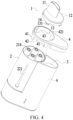
FIG. 4 is a schematic exploded view of an aerosol generation device according to an embodiment of this application; -
FIG. 5 is a schematic partial exploded view of an aerosol generation device according to an embodiment of this application; -
FIG. 6 is an another schematic exploded view of an aerosol generation device according to an embodiment of this application; and -
FIG. 7 is another schematic exploded view of an aerosol generation device according to an embodiment of this application. - In the accompanying drawings:
- 1. Mouthpiece; 11. Suction nozzle; 12. Base plate; 13. First limiting portion; 131. Snap portion; 14. First positioning portion;
- 2. Atomization assembly; 21. Atomizer; 211. Accommodating cavity; 212. Atomization core; 213. Air passage tube; 214. Flexible member; 215. Second air hole; 22. Housing;
- 3. Power supply assembly; 31. Battery cell; 32. Output electrode;
- 4. Holder; 41. Second limiting portion; 42. Connecting portion; 421. Guide groove; 43. Second positioning portion; 44. First air hole;
- 5. Seal ring.
- The technical solutions in the embodiments of this application are clearly and completely described below with reference to the accompanying drawings in the embodiments of this application. Apparently, the described embodiments are merely some rather than all of the embodiments of this application. Based on the embodiments of this application, all other embodiments obtained by a person of ordinary skill in the art without creative efforts shall fall within the protection scope of this application.
- The terms "first", "second", and "third" in this application are merely intended for a purpose of description, and shall not be understood as indicating or implying relative significance or implicitly indicating the number or order of indicated technical features. All directional indications (for example, upper, lower, left, right, front, and back) in the embodiments of this application are only used for explaining relative position relationships, movement situations, or the like among the various components in a specific posture (as shown in the accompanying drawings). If the specific posture changes, the directional indications change accordingly. In addition, terms "comprise", "include", and any variations thereof are intended to indicate non-exclusive inclusion. For example, a process, method, system, product, or device that includes a series of steps or units is not limited to the listed steps or units; and instead, further optionally includes a step or unit that is not listed, or further optionally comprises another step or unit that is intrinsic to the process, method, product, or device.
- "Embodiment" mentioned in this specification means that particular features, structures, or characteristics described with reference to the embodiment may be included in at least one embodiment of this application. The term appearing at different positions of the specification may not refer to the same embodiment or an independent or alternative embodiment that is mutually exclusive with another embodiment. A person skilled in the art explicitly or implicitly understands that the embodiments described in this specification may be combined with other embodiments.
- It should be noted that, when an element is referred to as "being fixed to" another element, the element may be directly on the another element, or an intervening element may be present. When an element is considered to be "connected to" another element, the element may be directly connected to the another element, or one or more intervening elements may exist between the element and the another element at the same time. The terms "vertical", "horizontal", "left", "right", and similar expressions used in this specification are merely used for purposes of illustration but not indicate a unique implementation.
- Referring to
FIG. 1 to FIG. 4 , an embodiment of this application provides an aerosol generation device. The aerosol generation device includes amouthpiece 1, apower supply assembly 3, and anatomization assembly 2 having one ormore atomizers 21. - The
mouthpiece 1 includes abase plate 12 and asuction nozzle 11 connected to thebase plate 12. Thesuction nozzle 11 is provided with a suction nozzle opening penetrating thebase plate 12. Thesuction nozzle 11 may be held in a mouth by a user. The user may inhale an aerosol provided by theatomizer 21 by inhaling thesuction nozzle 11. The aerosol may enter oral cavity of the user through the suction nozzle opening. Thebase plate 12 may be configured to support thesuction nozzle 11. In an example, thebase plate 12 may be connected to thesuction nozzle 11 to form an integrated structure. For example, thebase plate 12 may be integrally formed with thesuction nozzle 11. Alternatively, for example, thebase plate 12 and thesuction nozzle 11 are formed separately, and then connected to each other through assembly to form an integrated structure, to remain relatively stationary. In an example, thebase plate 12 and thesuction nozzle 11 are connected after being formed separately, and thesuction nozzle 11 is movable relative to thebase plate 12. - Each
atomizer 21 may have anaccommodating cavity 211. Theaccommodating cavity 211 is configured to accommodate a liquid substrate that can be atomized to generate an aerosol. A volume of theaccommodating cavity 211 may not exceed 5 ml, for example, the volume of theaccommodating cavity 211 may be approximately 2 ml. - The liquid substrate may include a liquid including a tobacco-containing substance containing volatile tobacco aroma compounds, or may be a liquid including a non-tobacco substance. The liquid substrate may include water, chemical solution, solvent, ethanol, plant extract, spice, a fragrance, vitamin mixture, and the like. The spice may include areca nut extract, menthol, peppermint, spearmint oil, various fruity aroma ingredients, and the like, but is not limited thereto. The fragrance may include components that can provide various aromas or flavors to the user. The vitamin mixture may be a mixture of at least one of vitamin A, vitamin B, vitamin C, and vitamin E, but is not limited thereto. Based on different attributes of the liquid substrate, the aerosol generation device may be used in different fields, such as medical treatment and electronic aerosol atomization.
- The "plurality of" means two or more. In the embodiment shown in
FIG. 4 , fouratomizers 21 are provided, but this is not limited thereto. At least two of the plurality ofatomizers 21 may be configured to accommodate different liquid substrates. The different liquid substrates include liquid substrates with different tastes or liquid substrates with different ingredients and ratios, so that the user may be provided with different inhalation experience by selecting theatomizer 21 in fluid communication with themouthpiece 1. Certainly, in an embodiment, all theatomizers 21 accommodate the same liquid substrate. - Each
atomizer 21 may further have anatomization core 212. Theatomization core 212 is in fluid communication with theaccommodating cavity 211. Theatomization core 212 is configured to atomize the liquid substrate, to generate an aerosol. Theatomization core 212 may include a liquid absorbing element and a heating element. The liquid absorbing element may be a porous body or a fiber that can absorb the liquid substrate and guide the liquid substrate into an atomization range of the heating element. The heating element is configured to atomize at least a part of the liquid substrate on the liquid absorbing element to form the aerosol. The heating element may be combined on the liquid absorbing element, so that the heating element can be integrally formed with the heating element. - Each
atomizer 21 may be further provided with anair passage tube 213. Theair passage tube 213 provides at least a part of an airflow passage in which theatomization core 212 is in fluid communication with themouthpiece 1. The aerosol generated by theatomization core 212 may enter themouthpiece 1 through the airflow passage. Theaccommodating cavity 211 may be arranged around theair passage tube 213, or theair passage tube 213 may be arranged on one side of theaccommodating cavity 211. - In an example, the
atomizer 21 may have an atomization compartment in fluid communication with theaccommodating cavity 211, theatomization core 212 is accommodated in the atomization compartment, theair passage tube 213 is in fluid communication with the atomization compartment, themouthpiece 1 is located above theaccommodating cavity 211, and the atomization compartment is located below theaccommodating cavity 211. - Alternatively, in another example, at least a part of the
atomization core 212 is arranged in theair passage tube 213, theair passage tube 213 is provided with a liquid guide hole, and theatomization core 212 is in fluid communication with theaccommodating cavity 211 through the liquid guide hole. The liquid substrate in theaccommodating cavity 211 may pass through the liquid guide hole to be absorbed by the liquid absorbing element and atomized by the heating element, or a part of the liquid absorbing element may pass through the liquid guide hole into theaccommodating cavity 211 to absorb and deliver the liquid substrate. - Referring to
FIG. 6 andFIG. 7 , the aerosol generation device further includes aholder 4. Theholder 4 is connected to theatomization assembly 2, and theholder 4 can protect theatomization assembly 2. In addition, themouthpiece 1 may be connected to theholder 4. Themouthpiece 1 is configured to be rotatable or movable relative to theholder 4 between a disengaged position and at least one locking position. Themouthpiece 1 is removable from theholder 1 when at the disengaged position, to remove the at least oneatomizer 21 in theatomization assembly 2. Connection of themouthpiece 1 to theholder 4 is limited when themouthpiece 1 is at the locking position, to remain theatomizer 21 in theatomization assembly 2. - When the
mouthpiece 1 needs to be connected to theholder 4 or theatomization assembly 2, or when the one ormore atomizers 21 need to be remained in theatomization assembly 2, themouthpiece 1 may be rotated or moved from the disengaged position to the locking position. Themouthpiece 1 can block the one ormore atomizers 21 from being removed from theatomization assembly 2. When themouthpiece 1 needs to be disengaged from theholder 4 or theatomization assembly 2, or when the one ormore atomizers 21 need to be removed from theatomization assembly 2, themouthpiece 1 may be rotated or moved from the locking position to the disengaged position, and then a force is applied to disengage themouthpiece 1 from theholder 4. - It should be noted that, when the
mouthpiece 1 is at the locking position relative to theholder 4, themouthpiece 1 cannot be disengaged from theholder 4 in a direction perpendicular to rotation or movement of themouthpiece 1 relative to theholder 4. - In some examples, one locking position is provided. In some examples, a plurality of locking positions are provided, and two adjacent locking positions are spaced from each other. In some examples, when the
mouthpiece 1 is connected to theholder 4 and themouthpiece 1 is at the locking position relative to theholder 4, themouthpiece 1 may be rotated or moved. - In an embodiment provided in this application, when the
mouthpiece 1 is at the locking position relative to theholder 4, themouthpiece 1 is further configured to be rotatable or movable relative to theatomization assembly 2, so that theair passage tube 213 in theatomizer 21 corresponds to the suction nozzle opening of thesuction nozzle 11 or to thebase plate 12. When theair passage tube 213 in theatomizer 21 corresponds to the suction nozzle opening of thesuction nozzle 11, thesuction nozzle 11 is in fluid communication with theair passage tube 213 in theatomizer 21. Specifically, when theair passage tube 213 in theatomizer 21 corresponds to the suction nozzle opening of thesuction nozzle 11, theair passage tube 213 in theatomizer 21 is in fluid communication with the suction nozzle opening of thesuction nozzle 11. When theair passage tube 213 in theatomizer 21 corresponds to thebase plate 12, theair passage tube 213 in theatomizer 21 is sealed by thebase plate 12, so that theatomizer 21 cannot be inhaled by the user. In other words, when theair passage tube 213 in theatomizer 21 corresponds to thebase plate 12, the air passage tube is in a locked state of a child lock. In this case, the aerosol generation device cannot generate the aerosol. Therefore, themouthpiece 1 by may be rotated or moved relative to theatomization assembly 2 to drive thebase plate 12 to correspond to theair passage tube 213 in theatomizer 21, so that theatomizer 21 is in the locked state of the child lock and cannot be inhaled. In the schematic diagram shown inFIG. 2 , thebase plate 12 of themouthpiece 1 corresponds to theair passage tube 213 in theatomizer 21. - Specifically, the locking position includes a first position and a second position, and the
mouthpiece 1 is configured to be rotatable or movable relative to theatomization assembly 2 between the first position and the second position. When themouthpiece 1 is rotated or moved to the first position, the suction nozzle opening is in communication with theair passage tube 213 in theatomizer 21. When themouthpiece 1 is rotated or moved to the second position, theair passage tube 213 in theatomizer 21 is sealed by the base plate. That is, when themouthpiece 1 is at the second position, theatomizer 21 associated with themouthpiece 1 is in the locked state of the child lock. - Based on the first aspect of this application, the child lock is unlocked by rotating or moving the
suction nozzle 11 relative to theatomization assembly 2, so that the suction nozzle opening of thesuction nozzle 11 is in fluid communication with theatomizer 21 associated with thesuction nozzle 11. - The aerosol generated by the
atomizer 21 may have two premises: First, theatomizer 21 is in fluid communication with the suction nozzle opening of thesuction nozzle 11, and second, thepower supply assembly 3 supplies power to theatomization core 212 of theatomizer 21. Therefore, when themouthpiece 1 is at the second position, and theair passage tube 213 in theatomizer 21 is sealed by thebase plate 12, an airflow passage between theatomizer 21 and the suction nozzle opening of thesuction nozzle 11 is cut off, so that theatomizer 21 is not in fluid communication with the suction nozzle opening. - Based on this, in an embodiment, the aerosol generation device further includes a control circuit and an airflow detector. The airflow detector is configured to detect whether an airflow parameter in the airflow passage or in the
air passage tube 213 reaches a threshold. The control circuit is configured to prohibit thepower supply assembly 3 from supplying power to theatomizer 21 when the airflow parameter is beyond the threshold. The airflow parameter may be a velocity, a pressure, or a temperature of the airflow. - The airflow detector may directly detect the airflow parameter. For example, the airflow detector may be at least partially exposed in the airflow passage or in the
air passage tube 213, so that the airflow detector can contact the airflow in the airflow passage or in theair passage tube 213. - The airflow detector may indirectly detect the airflow parameter. For example, a receiving cavity configured to receive the airflow detector is in fluid communication with the airflow passage or the
air passage tube 213. A change in the airflow parameter in the airflow passage or in theair passage tube 213 causes an airflow fluctuation or a pressure change in the receiving cavity, so that the airflow detector can indirectly detect an airflow change in the airflow passage or in the air passage tube by detecting a velocity, a direction, or a pressure of the airflow in the receiving cavity. - When the
atomizer 21 is in fluid communication with the suction nozzle opening of thesuction nozzle 11, the user inhales thesuction nozzle 11, causing an increase in an airflow velocity in the air flow passage or in theair passage tube 213, thereby causing a change in the airflow parameter in the airflow passage or in theair passage tube 213. When the airflow parameter reaches the threshold, the control circuit or the airflow detector determines that the user is inhaling the aerosol generation device. Then, the control circuit controls thepower supply 3 to supply power to theatomization core 212 of theatomizer 21, so that theatomizer 21 generates the aerosol, to meet an inhalation requirement of the user. When the airflow parameter is beyond the threshold, the control circuit or the airflow detector determines that the aerosol generation device is not inhaled by the user, or determines that the child lock of the aerosol generation device is not unlocked. Therefore, the control circuit prohibits thepower supply assembly 3 from supplying power to theatomization core 212 of theatomizer 21, so that power can be saved, and the aerosol generation device can be prevented from being inhaled by inappropriate people. - According to a second aspect of this application, only one
atomizer 21 is provided in theatomization assembly 2, so that the only oneatomizer 21 in theatomization assembly 2 can be associated with thesuction nozzle 11 of themouthpiece 1. When thesuction nozzle 11 is associated with theatomizer 21, thesuction nozzle 11 can be located at the first position by rotating or moving themouthpiece 1 relative to theholder 4, so that the suction nozzle opening of thesuction nozzle 11 corresponds to theair passage tube 213 in theatomizer 21, and the suction nozzle opening of thesuction nozzle 11 is in fluid communication with theair passage tube 213 in theatomizer 21. Alternatively, thesuction nozzle 11 can be located at the second position, so that thebase plate 12 corresponds to theair passage tube 213 in theatomizer 21, and theair passage tube 213 in theatomizer 21 associated with thesuction nozzle 11 is sealed. - Therefore, by rotating or moving the
mouthpiece 1 relative to theatomization assembly 1 or rotating or moving themouthpiece 1 relative to theonly atomizer 21 in theatomization assembly 1, the suction nozzle opening of thesuction nozzle 11 can be in fluid communication with theair passage tube 213 in theatomizer 21 or the communication can be cut off, thereby completing locking and unlocking of the child lock. - In addition, when the aerosol generation device is temporarily not in use, by moving the
mouthpiece 1 relative to theatomization assembly 1, theair passage tube 213 in theatomizer 21 is sealed by thebase plate 12, achieving a dustproof effect. - According to a third aspect of this application, the
atomization assembly 2 includes a plurality ofatomizers 21 independent of each other. Eachatomizer 21 can independently generate an aerosol. Thesuction nozzle 11 is configured to be selectively associated with one of theatomizers 21. When thesuction nozzle 11 is associated with one of theatomizers 21, by rotating and moving themouthpiece 1 relative to theatomizer 21 associated with thesuction nozzle 11 between the first position and the second position, the suction nozzle opening of thesuction nozzle 11 is brought into fluid communication with theair passage tube 213 in theatomizer 21 associated with thesuction nozzle 11, or thebase plate 12 is brought into correspondence with theair passage tube 213 in theatomizer 21 associated with thesuction nozzle 11, so that thesuction nozzle 11 and theair passage tube 213 in theatomizer 21 associated with thesuction nozzle 11 are sealed by thebase plate 12. When thesuction nozzle 11 is associated with any one of theatomizers 21, thesuction nozzle 11 is at the locking position relative to theholder 4. - It should be noted that, when a plurality of
atomizers 21 are provided, theholder 4 corresponding to eachatomizer 21 has the first position and the second position that are associated with eachatomizer 21. In other words, eachatomizer 21 may have the first position and the second position that are associated with eachatomizer 21. When thesuction nozzle 11 of themouthpiece 1 is associated with anatomizer 21, thesuction nozzle 11 is associated with both the first position and the second position that are associated with theatomizer 21. - In an embodiment, the
mouthpiece 1 is detachably connected to theatomization assembly 2, and themouthpiece 1 has a plurality of connection orientations with theatomization assembly 2. The plurality of connection orientations may be set along a circumference or may be set along a line. When themouthpiece 1 is connected to theatomization assembly 2 in different connection orientations, thesuction nozzle 11 is associated withdifferent atomizers 21. In this embodiment, after themouthpiece 1 is connected to theatomization assembly 2 and/or theholder 4 in one of the connection orientations, when themouthpiece 1 is rotated or moved to the first position relative to theatomizer 21 associated with thesuction nozzle 11, the suction nozzle opening is in communication with theair passage tube 213 in theatomizer 21. When themouthpiece 1 is rotated or moved to the second position relative to theatomizer 21 associated with thesuction nozzle 11, theair passage tube 213 in theatomizer 21 is sealed by thebase plate 12. - Therefore, the
mouthpiece 1 may be first disengaged from theatomization assembly 2, and then a connection orientation between themouthpiece 1 and theatomization assembly 2 is changed, so that thesuction nozzle 11 is associated with a selectedatomizer 21. - Alternatively, there may be a plurality of connection orientations between the
mouthpiece 1 and theholder 4. Each connection orientation between themouthpiece 1 and theholder 4 is separately matched with eachatomizer 21 in theatomization assembly 2, so that theatomizer 21 associated with thesuction nozzle 11 may be replaced by changing the connection orientation between themouthpiece 1 and theholder 4. Therefore, themouthpiece 1 may be detachably connected to theholder 4. The connection between themouthpiece 1 and theatomization assembly 2 through theholder 4 includes: while being connected to theholder 4, themouthpiece 1 is further directly connected to theatomization assembly 2; or themouthpiece 1 is connected to theholder 4, and theatomization assembly 2 is connected to theholder 4, but themouthpiece 1 and theatomization assembly 2 are spaced apart and are not directly connected. - After the
mouthpiece 1 is connected to theatomization assembly 2 and/or theholder 4 in one of the connection orientations, thesuction nozzle 11 is rotatable or movable relative to theatomizer 21 associated with thesuction nozzle 11 between the first position and the second position. - As an example, a stroke of the rotation or movement is limited, and the
suction nozzle 11 can only be associated with theatomizer 21 matching the connection orientation, but cannot be associated with theatomizer 21 matching another connection orientation by rotating or moving thesuction nozzle 11 relative to theatomization assembly 2 and/or theholder 4 while being connected to theatomization assembly 2 and/or theholder 4. - While the
mouthpiece 1 is connected to theatomization assembly 2 and/or theholder 4, the rotation of themouthpiece 1 is limited within a predetermined angle range. During the rotation of themouthpiece 1 within the predetermined angle range, the suction nozzle opening of themouthpiece 1 can only be in communication with anair passage tube 213 in one of theatomizers 21. - As an example, the stroke is not limited. While the
mouthpiece 1 is connected to theatomization assembly 2 and/or theholder 4, thesuction nozzle 11 can be associated with theatomizer 21 matching one connection orientation, and rotated or moved to be associated with theatomizer 21 matching another connection orientation. In other words, after themouthpiece 1 is rotated or moved from the first position to the second position relative to theatomizer 21 associated with themouthpiece 1, themouthpiece 1 may further be rotated or moved in the original proceeding direction to the first position of theatomizer 21 matching the another connection orientation. - For example: When the
mouthpiece 1 is at the locking position, themouthpiece 1 is configured to be rotatable or movable to a third position relative to the atomization assembly or relative to theatomizer 21 currently associated with themouthpiece 1. When themouthpiece 1 is at the first position, the suction nozzle opening of themouthpiece 1 is in fluid communication with theair passage tube 213 in one of theatomizers 21, and when themouthpiece 1 is at the third position, the suction nozzle opening of themouthpiece 1 is in fluid communication with theair passage tube 213 in anotheratomizer 21. The second position may be between the first position and the third position. - In an embodiment, both the
mouthpiece 1 and theatomization assembly 2 is rotatable or movable relative to theholder 4, and the rotation or movement of themouthpiece 1 relative to theholder 4 and the rotation or movement of theatomization assembly 2 relative to theholder 4 are independent of each other. When thesuction nozzle 11 moves relative to theholder 4, theatomization assembly 2 may be stationary relative to theholder 4. When theatomization assembly 2 moves relative to theholder 4, thesuction nozzle 11 may be stationary relative to theholder 4. One selectedatomizer 21 in theatomization assembly 2 may be associated with thesuction nozzle 11 by rotating or moving theatomization assembly 2 relative to themouthpiece 1 connected to theholder 4. - After the selected
atomizer 21 in theatomization assembly 2 is associated with thesuction nozzle 11 by rotating or moving theatomization assembly 2 relative to themouthpiece 1 connected to theholder 4, thesuction nozzle 11 is rotated or moved relative to the associatedatomizer 21 between the first position and the second position. Alternatively, after thesuction nozzle 11 is rotated or moved to an appropriate position relative to theatomizer 21 currently associated with thesuction nozzle 11 between the first position and the second position, thesuction nozzle 11 may be associated with anotheratomizer 21 in theatomization assembly 2 by rotating or moving theatomization assembly 2 relative to themouthpiece 1 connected to theholder 4. - Based on this, there may be one or more connection orientations between the
mouthpiece 1 and theholder 4, and themouthpiece 1 may be connected to theatomization assembly 2 by being connected to theholder 4. However, themouthpiece 1 is rotatable or movable relative to theatomizer 21 associated with themouthpiece 1 between the first position and the second position by independently rotating or moving relative to theholder 4, so that the suction nozzle opening is in communication with theair passage tube 213 in theatomizer 21, or theair passage tube 213 in theatomizer 21 is sealed by thebase plate 12. Therefore, themouthpiece 1 is rotatable or movable relative to theholder 4 between the same first position and the same second position without changing the connection orientation between themouthpiece 1 and theholder 4 regardless of which atomizer 21 thesuction nozzle 11 is associated with. - In an embodiment, the
power supply assembly 3 includes abattery cell 31 and anoutput electrode 32, and thebattery cell 31 may be a lithium ion battery. Alternatively, thebattery cell 31 may be a nickel-metal hydride battery, a nickel-cadmium battery, or a lithium-based battery, for example, a lithium cobalt battery, a lithium iron phosphate battery, a lithium titanate battery, or a lithium polymer battery. Thecontrol circuit 32 may control an output of thebattery cell 31, for example, cause thebattery cell 31 to output an alternating current or a direct current, or for example, cause thebattery cell 31 to output a current or a voltage in the form of a pulse. - The
battery cell 31 outputs power to theatomization assembly 2 through theoutput electrode 32, for the correspondingatomizer 21 to generate the aerosol. - The
atomization assembly 2 is movable relative to theoutput electrode 32, so that theoutput electrode 32 is selectively electrically connected to one of theatomizers 21, thereby enabling thepower supply assembly 3 to supply power to one of theatomizers 21. Theatomizer 21 electrically connected to theoutput electrode 32 may be replaced by moving theatomization assembly 2 relative to theoutput electrode 32. When thesuction nozzle 11 is in fluid communication with theair passage tube 213 in theatomizer 21 associated with thesuction nozzle 11, thesuction nozzle 11 may correspond to theoutput electrode 32, and theatomizer 21 may be electrically connected to theoutput electrode 32. - Specifically, the
atomization assembly 2 is further rotatable or movable relative to theholder 4 while being connected to theholder 4. An outer side surface of theatomization assembly 2 may be at least partially exposed outside theholder 4, thereby providing an external operation to rotate theatomization assembly 2. - As an example, referring to
FIG. 2 ,FIG. 3 , andFIG. 6 , theoutput electrode 32 is connected to theholder 4. Theatomization assembly 2 is rotatable or movable relative to theoutput electrode 32 by rotating or moving relative to theholder 4, so that theoutput electrode 32 is selectively electrically connected to one of theatomizers 21. When theatomization assembly 2 rotates or moves relative to theholder 4, theoutput electrode 32 may be stationary relative to theholder 4. - In an embodiment, when the
mouthpiece 1 is at the second position of theatomizer 21 associated with thesuction nozzle 11, or when thesuction nozzle 11 is not in fluid communication with theair passage tube 213 in theatomizer 21 associated with thesuction nozzle 11, thebase plate 12 simultaneously abuts against all theatomizers 21, and seals theair passage tube 213 in all theatomizers 21, so that the suction nozzle opening of thesuction nozzle 11 and theair passage tube 213 in all theatomizers 21 remain cut off. - When the
mouthpiece 1 is at the first position of theatomizer 21 associated with thesuction nozzle 11, or when thesuction nozzle 11 is in fluid communication with theair passage tube 213 in theatomizer 21 associated with thesuction nozzle 11, thebase plate 12 may abut against the remainingatomizers 21 that are not associated with thesuction nozzle 11, and seal theair passage tubes 213 in theseatomizers 21, so that the suction nozzle opening of thesuction nozzle 11 is only in communication with theair passage tube 213 in the associatedatomizer 21. - Based on the first aspect, the second aspect, and/or the third aspect of this application, referring to
FIG. 2 andFIG. 7 , theatomization assembly 2 includes ahousing 22. At least a part of thehousing 22 arranged around the one ormore atomizers 21 may be transparent, so that theatomizers 21 may be observed visually through thehousing 22. At least a part of a wall defining theaccommodating cavity 211 in theatomizer 21 may also be transparent, so that at least a part of theaccommodating cavity 211 is visible. Vision may successively pass through thehousing 22 and the wall defining theaccommodating cavity 211 to observe theaccommodating cavity 211 in theatomizer 21, for example, to observe a remaining amount of the liquid substrate in theaccommodating cavity 211, to provide a basis for the user to replace theatomizer 21 associated with themouthpiece 1. - When only one
atomizer 21 is provided in theatomization assembly 2, thehousing 22 may form a wall defining theaccommodating cavity 211, so that when at least a part of thehousing 22 is transparent, at least a part of theaccommodating cavity 211 can be directly observed. When theatomization assembly 2 includes a plurality ofatomizers 21, thehousing 22 may be provided with a specialtransparent window 221 corresponding to eachatomizer 21, so that accommodatingcavities 211 indifferent atomizers 21 can be observed throughdifferent windows 221. - It should be noted that, it is optional rather than mandatory that at least a part of the
housing 22 arranged around the plurality ofatomizers 21 is transparent. - Based on the first aspect, the second aspect, and/or the third aspect of this application, referring to
FIG. 4 , theholder 4 is at least partially arranged between themouthpiece 1 and theatomization assembly 2, themouthpiece 1 is connected to theholder 4, and theholder 4 is configured to limit the stroke of the rotation or movement of themouthpiece 1 relative to theatomization assembly 2. - As an example, the
holder 4 is provided with an opening, and at least a part of themouthpiece 1 can be accommodated in the opening to be connected to theholder 4. When themouthpiece 1 is removed from theholder 4, the opening is exposed, so that at least oneatomizer 21 can be removed through the opening. When themouthpiece 1 is at the locking position relative to theholder 4, the disengagement of themouthpiece 1 from the opening is limited, and at least a part of the opening is blocked by themouthpiece 1, so that theatomizer 21 can be retained in theatomization assembly 2. - At least a part of the
base plate 12 may be accommodated in the opening. Thesuction nozzle 11 extends from one side of thebase plate 12 and faces away from a direction of the opening in an extension direction. The suction nozzle opening of thesuction nozzle 11 penetrates thebase plate 12 to be in communication with one of theatomizers 21 in theatomization assembly 2. - As an example, referring to
FIG. 4 andFIG. 5 , theholder 4 is configured to limit a rotation angle of themouthpiece 1 relative to theatomization assembly 2, so that after one of the connection orientations of thebase plate 12 is inserted into an opening of theholder 4, the rotation of themouthpiece 1 relative to theholder 4 is limited within a predetermined angle range, so that themouthpiece 1 cannot be rotated by 360° relative to theholder 4. For example, after themouthpiece 1 is connected to theholder 4 in one of the connection orientations, a maximum rotation angle of themouthpiece 1 relative to theholder 4 is less than or equal to 90°. Alternatively, for example, after themouthpiece 1 is connected to theholder 4 in one of the connection orientations, a maximum rotation angle of themouthpiece 1 relative to theholder 4 is less than or equal to 180°. - The rotation angle of the
mouthpiece 1 is limited by theholder 4, so that themouthpiece 1 can only be associated with one of theatomizers 21, but cannot be rotated to be associated with anotheratomizer 21. In this way, when the user needs to lock the child lock, thesuction nozzle 11 does not proceed beyond a locked position to be in fluid communication with the anotheratomizer 21 due to excessive rotation. - For example, referring to
FIG. 5 , one of theholder 4 and themouthpiece 1 is provided with a first limitingportion 13, and the other is provided with a second limitingportion 41. When themouthpiece 1 is connected to theholder 4, the first limitingportion 13 is located between two adjacent second limitingportions 41, and the first limitingportion 13 is limited to be rotatable or movable only between the two adjacent second limitingportions 41, so that the predetermined angle range is limited by the two adjacent second limitingportions 41. - In the embodiment shown in
FIG. 5 , themouthpiece 1 includes the first limitingportion 13, the first limitingportion 13 is connected to thebase plate 12, and the first limitingportion 13 may be integrally formed with thebase plate 12. Theholder 4 includes the second limitingportion 41. - As an example, the aerosol generation device further includes a connecting
portion 42 between two adjacent second limitingportions 41. The connectingportion 42 may be integrally formed with the second limitingportion 41. Specifically, both the connectingportion 42 and the second limitingportion 41 may be components of theholder 4. The connectingportion 42 may be at least a part of a wall defining the opening of theholder 4. The wall may be provided with a plurality ofguide grooves 421 extending in a longitudinal direction. The plurality ofguide grooves 421 define an orientation of the opening through which themouthpiece 1 is inserted into theholder 4. - The first limiting
portion 13 is provided with asnap portion 131. Thesnap portion 131 may be a protrusion or a barb formed on the first limitingportion 13. Thesnap portion 131 may be an elastic piece or an elastic arm formed on the first limitingportion 13. Thesnap portion 131 may be integrally formed with the first limitingportion 13. - When the
mouthpiece 1 is at the disengaged position or the locking position relative to theholder 4, thesnap portion 131 is located between two adjacent second limitingportions 41 and thesnap portion 131 is in interference fit, for example, a snap connection, with the connectingportion 42. Through the interference fit between thesnap portion 131 and the connectingportion 42, themouthpiece 1 is connected to theholder 4, and the disengagement of themouthpiece 1 from theholder 4 is limited, or the disengagement of themouthpiece 1 from the opening of theholder 4 is limited. - In the embodiment shown in
FIG. 5 andFIG. 6 , theguide groove 421 is provided on the connectingportion 42. Theguide groove 421 is configured to guide thesnap portion 131 to be between two adjacent second limitingportions 41. Then, by rotating themouthpiece 1 relative to theholder 4 in a first direction, thesnap portion 131 is rotated relative to the connectingportion 42 in the first direction, thereby staggering thesnap portion 131 from theguide groove 421. Therefore, thesnap portion 131 is in interference fit with the connectingportion 42, to prevent the disengagement of themouthpiece 1 from theholder 4 or from theatomization assembly 2. Then, by rotating themouthpiece 1 relative to theholder 4 in a second direction opposite to the first direction, thesnap portion 131 is rotated relative to the connectingportion 42 in the second direction opposite to the first direction, so that thesnap portion 131 corresponds to theguide groove 421. In this case, themouthpiece 1 is rotated or moved relative to theholder 4 from the locking position to the disengaged position. In this case, themouthpiece 1 may be lifted in the longitudinal direction, to disengage themouthpiece 1 from theholder 4 or theatomization assembly 2. - In other words, the
mouthpiece 1 and theholder 4 or theatomization assembly 2 may be in a screwing connection. Through the screwing connection between themouthpiece 1 and theholder 4 or theatomization assembly 2, the connection between themouthpiece 1 and theholder 4 or theatomization assembly 2 is removable. - It should be noted that, alternatively, the connection between the
mouthpiece 1 and theholder 4 or theatomization assembly 2 is removable in other manners than the screwing connection, for example, a snap connection between themouthpiece 1 and theatomization assembly 2 or between themouthpiece 1 and theholder 4, or a magnetic connection between themouthpiece 1 and theatomization assembly 2 or between themouthpiece 1 and theholder 4. - It should be noted that, after the
mouthpiece 1 is connected to theholder 4 or theatomization assembly 2 and before themouthpiece 1 is rotated relative to theholder 4 or theatomization assembly 2, thesnap portion 131 on themouthpiece 1 corresponds to theguide groove 421. This position is referred to as the disengaged position. Then, by rotating themouthpiece 1, thesnap portion 131 on themouthpiece 1 is staggered from theguide groove 421, thereby entering the locking position. - The first position may be located between the disengaged position and the second position. Therefore, by rotating the
mouthpiece 1 from the disengaged position, themouthpiece 1 at the locking position may be rotated to the first position, and by continuing to rotate, themouthpiece 1 may be rotated from the first position to the second position. - The second position may be located between the disengaged position and the first position. Therefore, by rotating the
mouthpiece 1 from the disengaged position, themouthpiece 1 at the locking position may be rotated to the second position, and by continuing to rotate, themouthpiece 1 may be rotated from the second position to the first position. - As an example, the connecting
portion 42 includes two dents spaced apart, and the two dents respectively correspond to the first position and the second position. Correspondingly, themouthpiece 1 may be provided with a protrusion. Referring toFIG. 4 andFIG. 5 , a plurality of connectingportions 42 are provided, and the plurality of connectingportions 42 are distributed in a circumferential direction. Each connectingportion 42 may be associated with anatomizer 21. Therefore, when themouthpiece 1 is rotated or moved to the first position relative to theatomizer 21 associated with themouthpiece 1, the protrusion on themouthpiece 1 corresponds to one dent of the connectingportion 42, and fit between the protrusion and the dent is used for defining the first position. When themouthpiece 1 is rotated or moved to the second position relative to theatomizer 21 associated with themouthpiece 1, the protrusion on themouthpiece 1 corresponds to the other dent of the connectingportion 42, and fit between the protrusion and the dent is used for defining the second position. The fit between the protrusion and the dent further helps to retain themouthpiece 1 at the first position or the second position more stably, or helps to warn the user that themouthpiece 1 reaches the first position or the second position, so that the user stops continuing to rotate or move themouthpiece 1 in the original proceeding direction. - Alternatively, one of the
holder 4 and themouthpiece 1 may be provided with afirst positioning portion 14, and the other may be provided with asecond positioning portion 43. The first position and the second position are positioned by using thefirst positioning portion 14 or thesecond positioning portion 43. - As an example, when the
mouthpiece 1 is rotated or moved to the first position relative to theatomizer 21 associated with themouthpiece 1, or when themouthpiece 1 is in fluid communication with theair passage tube 213 in theatomizer 21 associated with themouthpiece 1, thefirst positioning portion 14 and thesecond positioning portion 43 are interlocked, to hinder movement of themouthpiece 1 relative to theatomization assembly 2, and help to maintain a stable fluid communication state between thesuction nozzle 11 and theatomizer 21 associated with thesuction nozzle 11. When themouthpiece 1 is rotated or moved to the second position relative to theatomizer 21 associated with themouthpiece 1, thefirst positioning portion 14 and thesecond positioning portion 43 are interlocked, so that the child lock maintains a stable locked state. - For example, referring to
FIG. 5 , thefirst positioning portion 14 is a component of themouthpiece 1. Specifically, thefirst positioning portion 14 may be provided on the first limitingportion 13 of themouthpiece 1. Each first limitingportion 13 may be provided with at least onefirst positioning portion 14, or at least one of the plurality of first limitingportions 13 is provided with thefirst positioning portion 14. Thesecond positioning portion 43 is a component of theholder 4. Specifically, thesecond positioning portion 43 may be provided on the connectingportion 42 of theholder 4. Each connectingportion 42 may be provided with at least onesecond positioning portion 43, or at least one of the plurality of connectingportions 42 is provided with thesecond positioning portion 43. - One of the
first positioning portion 14 and thesecond positioning portion 43 may be a protrusion, and the other may be a dent matching the protrusion. When the protrusion is embedded in the dent, the relative movement between themouthpiece 1 and theholder 4 can be prevented to some extent. - In the embodiment shown in
FIG. 5 , one connectingportion 42 is provided with twosecond positioning portions 43, and a first limitingportion 12 corresponding to the connectingportion 43 is provided with onefirst positioning portion 14. When thesuction nozzle 11 is in stable fluid communication with theatomizer 21 associated with thesuction nozzle 11, thefirst positioning portion 14 corresponds to and engages with one of thesecond positioning portions 43. When the child lock needs to maintain the stable locked state, thefirst positioning portion 14 corresponds to and engages with the othersecond positioning portion 43. - As an example, when the
first positioning portion 14 corresponds to thesecond positioning portion 43, the aerosol generation device can generate a sensory prompt signal to prompt themouthpiece 1 to enter the locking position, or prompt that themouthpiece 1 is in fluid communication with theatomizer 21 associated with themouthpiece 1, or prompt that theoutput electrode 32 is electrically connected to theatomizer 21 associated with thesuction nozzle 11. The sensory prompt signal may be one or more of sound, light, and vibration. The sensory prompt signal may be a vibration signal or a sound signal generated when thefirst positioning portion 14 is moved to engage with thesecond positioning portion 43. Alternatively, a signal acquisition circuit on the control circuit may generate a change in an electrical parameter when thefirst positioning portion 14 is moved to correspond to thesecond positioning portion 43, and then the control circuit can control, based on the change in the electrical parameter, an LED light, a player, a motor, or the like to generate one or more signals of sound, light, and vibration. - Based on the first aspect, the second aspect, and/or the third aspect of this application, referring to
FIG. 2 andFIG. 3 , the aerosol generation device further includes aflexible member 214. Theflexible member 214 elastically abuts against themouthpiece 1 and theatomization assembly 2, to provide friction that hinders the rotation or movement of themouthpiece 1 relative to theatomization assembly 2, which helps to prevent unexpected rotation or movement of themouthpiece 1 relative to theatomization assembly 2, helps to maintain a stable fluid communication state between thesuction nozzle 11 and theatomizer 21 associated with thesuction nozzle 11, or helps to maintain a stable locked state of the child lock. - As an example, referring to
FIG. 4 andFIG. 6 , theflexible member 214 is combined on theatomizer 21, and theflexible member 214 includes afirst air passage 2141 in fluid communication with theair passage tube 213. When thesuction nozzle 11 corresponds to the only or one of theair passage tubes 213, the correspondingfirst air passage 2141 is in fluid communication with theair passage tube 213 and thesuction nozzle 11. The aerosol in theair passage tube 213 can be transferred to thesuction nozzle 11 through thefirst air passage 2141. - An upper end of the
air passage tube 213 may be embedded in theflexible member 214. In an airflow direction, thefirst air passage 2141 is located downstream of theair passage tube 213, so that theflexible member 214 can be compressed and deformed by themouthpiece 1 and elastically abut against themouthpiece 1. - When the
mouthpiece 1 is in interference fit with theholder 4 through thesnap portion 131 and the connectingportion 42, the interference fit between themouthpiece 1 and theholder 4 can provide a force for theatomizer 21 and themouthpiece 1 to abut against theflexible member 214, and the force can compress and deform theflexible member 214. - When the
mouthpiece 1 is rotated or moved to the second position, theflexible member 214 elastically abuts against thebase plate 12 of themouthpiece 1, so that the connection between theflexible member 214 and thebase plate 12 is a sealed connection, which can prevent exchange and convection between theair passage tube 213 and the external air or the airflow in anotherair passage tube 213 through thefirst air passage 2141. - Based on the first aspect, the second aspect, and/or the third aspect of this application, referring to
FIG. 6 andFIG. 7 , theholder 4 includes an air intake passage in communication with the outside, and theholder 4 is provided with afirst air hole 44 in fluid communication with the air intake passage. Thefirst air hole 44 may be provided in parallel with two ormore output electrodes 32, for example, may be provided between two ormore output electrodes 32. Eachatomizer 21 is provided with an independentsecond air hole 215, and thesecond air hole 215 is in fluid communication with theair passage tube 213 in the correspondingatomizer 21. - When the
output electrode 32 is electrically connected to one of theatomizers 21, thefirst air hole 44 corresponds to thesecond air hole 215 on theatomizer 21 electrically connected to theoutput electrode 32, so that air can be transferred from thefirst air hole 44 to the correspondingsecond air hole 215. - A
seal ring 5 may be provided at a periphery of thefirst air hole 44 or eachsecond air hole 215, to ensure that when air in thefirst air hole 44 is transferred to thesecond air hole 215 on theatomizer 21 electrically connected to theoutput electrode 32, the air does not leak, which helps to improve the detection sensitivity and accuracy of the airflow detector. - It should be noted that, the specification of this application and the accompanying drawings thereof illustrate preferred embodiments of this application, but this application is not limited to the embodiments described in the specification. Further, a person of ordinary skill in the art may make improvements or variations according to the foregoing description, and all the improvements and variations shall fall within the protection scope of the appended claims of this application.
Claims (15)
- An aerosol generation device, comprising:a mouthpiece (1);an atomization assembly (2), comprising at least one atomizer (21) configured to heat a liquid substrate to generate an aerosol; anda holder (4), connected to the atomization assembly (2) and configured to hold the atomization assembly (2), wherein the holder (4) is provided with an opening, and at least a part of the mouthpiece (1) is accommodated in the opening to be connected to the holder (4),wherein:the mouthpiece (1) is configured to be rotatable or movable relative to the holder (4) between a disengaged position and at least one locking position;the mouthpiece (1) is removable from the holder (4) when at the disengaged position, to remove the at least one atomizer (21) through the opening; anddisengagement of the mouthpiece (1) from the opening is prevented when the mouthpiece (1) is at the locking position, to keep the atomizer (21) in the atomization assembly (2).
- The aerosol generation device according to claim 1, wherein the locking position comprises a first position and a second position, and the mouthpiece (1) is configured to be rotatable or movable relative to the atomization assembly (2) between the first position and the second position, wherein when the mouthpiece (1) is at the first position, a suction nozzle opening of the mouthpiece (1) is in fluid communication with an air passage in the atomizer (21), and when the mouthpiece (1) is at the second position, the mouthpiece (1) seals the air passage in the atomizer (21).
- The aerosol generation device according to claim 2, wherein the atomization assembly (2) comprises a plurality of atomizers (21) independent of each other, wherein when the mouthpiece is at the first position, the suction nozzle opening of the mouthpiece (1) is in communication with an air passage in only one of the atomizers (21), and when the mouthpiece (1) is at the second position, the mouthpiece (1) seals air passages in all the atomizers (21).
- The aerosol generation device according to claim 2, wherein:the atomization assembly (2) comprises a plurality of atomizers (21) independent of each other; andthe locking position further comprises a third position,wherein:when the mouthpiece (1) is at the first position, the suction nozzle opening of the mouthpiece (1) is in fluid communication with an air passage in one of the atomizers (21); andwhen the mouthpiece (1) is at the third position, the suction nozzle opening of the mouthpiece (1) is in fluid communication with an air passage in another of the atomizers (21).
- The aerosol generation device according to claim 1, wherein:the atomization assembly (2) comprises a plurality of atomizers (21) independent of each other, and each of the atomizers (21) is provided with an air passage tube (213); andthe mouthpiece (1) is configured to be insertable into the opening in a plurality of different orientations on a circumference and connected to the holder (4),wherein:rotation of the mouthpiece (1) is limited within a predetermined angle range when the mouthpiece (1) is inserted into the opening in one of the orientations; anda suction nozzle opening of the mouthpiece (1) is in communication with the air passage tube (213) in only one of the atomizers (21) during the rotation of the mouthpiece (1) within the predetermined angle range.
- The aerosol generation device according to claim 5, wherein:the mouthpiece (1) comprises a base plate (12) that is at least partially accommodated in the opening, and further comprises a suction nozzle (11) extending from one side of the base plate (12); anda suction nozzle opening of the mouthpiece (1) penetrates the base plate (12) to be in communication with one of the atomizers (21).
- The aerosol generation device according to claim 5, wherein:the holder (4) comprises a wall defining the opening;the wall is provided with a plurality of guide grooves (421) extending in a longitudinal direction; andthe plurality of guide grooves (421) define an orientation in which the mouthpiece (1) is inserted into the opening.
- The aerosol generation device according to claim 5, wherein:the mouthpiece (1) is provided with a first limiting portion (13), and the holder (4) is provided with a plurality of second limiting portions (41); andthe first limiting portion (13) is located between two adjacent second limiting portions (41), and the first limiting portion (13) is movable between two adjacent second limiting portions (41), to limit the rotation of the mouthpiece (1) within the predetermined angle range.
- The aerosol generation device according to claim 8, wherein the holder (4) further comprises a connecting portion (42) located between two adjacent second limiting portions (41), and the first limiting portion (13) has a snap portion (131) thereon, wherein
the snap portion (131) is in interference fit with the connecting portion (42) to prevent disengagement of the mouthpiece (1) from the opening. - The aerosol generation device according to claim 1, wherein the aerosol generation device further comprises a flexible member (214), and the flexible member (214) is elastically abutted between the mouthpiece (1) and the atomization assembly (2) to provide friction that hinders rotation or movement of the mouthpiece (1) relative to the atomization assembly (2).
- The aerosol generation device according to claim 1, wherein:the mouthpiece (1) is provided with a first positioning portion (14), and the holder (4) is provided with a second positioning portion (43); andthe first positioning portion (14) and the second positioning portion (43) is interlocked to hinder movement of the mouthpiece (1) relative to the atomization assembly (2).
- The aerosol generation device according to claim 1, wherein:the mouthpiece (1) is provided with a first positioning portion (14), and the holder (4) is provided with a second positioning portion (43); andthe aerosol generation device is configured to generate a sensory prompt signal when the first positioning portion (14) is aligned with the second positioning portion (43), to prompt the mouthpiece (1) to enter the locking position.
- The aerosol generation device according to claim 1, wherein the atomization assembly (2) comprises a plurality of atomizers (21) independent of each other, and the atomization assembly (2) is configured to be rotatable relative to the holder (4) to selectively connect one of the atomizers (21) to a power supply.
- The aerosol generation device according to claim 13, wherein an outer side surface of the atomization assembly (2) is partially exposed to an exterior of the holder (4), to provide an external operation to make the atomization assembly (2) rotatable.
- An aerosol generation device, comprising:a mouthpiece (1), provided with a suction nozzle opening;an atomization assembly (2), comprising a plurality of atomizers (21) independent of each other, wherein the atomizer (21) is configured to heat a liquid substrate to generate an aerosol, and each of the atomizers (21) is provided with an air passage tube (213); anda holder (4), connected to the atomization assembly (2) and configured to hold the atomization assembly (2), wherein the holder (4) is provided with an opening, and at least a part of the mouthpiece (1) is accommodated in the opening,wherein:the mouthpiece (1) is configured to be insertable into the opening in a plurality of different orientations on a circumference and connected to the holder (4);rotation of the mouthpiece (1) is limited within a predetermined angle range when the mouthpiece (1) is inserted into the opening in one of the orientations; andthe suction nozzle opening of the mouthpiece (1) is in communication with the air passage tube (213) in only one of the atomizers (21) during the rotation of the mouthpiece (1) within the predetermined angle range.
Applications Claiming Priority (1)
| Application Number | Priority Date | Filing Date | Title |
|---|---|---|---|
| CN202322310789.8U CN220875919U (en) | 2023-08-28 | 2023-08-28 | Aerosol generating device |
Publications (2)
| Publication Number | Publication Date |
|---|---|
| EP4527218A2 true EP4527218A2 (en) | 2025-03-26 |
| EP4527218A3 EP4527218A3 (en) | 2025-06-04 |
Family
ID=90871335
Family Applications (1)
| Application Number | Title | Priority Date | Filing Date |
|---|---|---|---|
| EP24196763.7A Pending EP4527218A3 (en) | 2023-08-28 | 2024-08-27 | Aerosol generation device |
Country Status (2)
| Country | Link |
|---|---|
| EP (1) | EP4527218A3 (en) |
| CN (1) | CN220875919U (en) |
Families Citing this family (5)
| Publication number | Priority date | Publication date | Assignee | Title |
|---|---|---|---|---|
| CN221962861U (en) * | 2023-12-11 | 2024-11-08 | 深圳市合元科技有限公司 | Electronic atomizing device |
| CN121080669A (en) * | 2024-06-06 | 2025-12-09 | 思摩尔国际控股有限公司 | Atomizing device and aerosol generating device |
| WO2025251784A1 (en) * | 2024-06-06 | 2025-12-11 | 思摩尔国际控股有限公司 | Atomization device and aerosol-generating apparatus |
| CN121080673A (en) * | 2024-06-06 | 2025-12-09 | 思摩尔国际控股有限公司 | Atomizing device and aerosol generating device |
| WO2026052550A1 (en) * | 2024-09-04 | 2026-03-12 | Philip Morris Products S.A. | Hybrid aerosol-generating device |
Family Cites Families (4)
| Publication number | Priority date | Publication date | Assignee | Title |
|---|---|---|---|---|
| EP3167728B1 (en) * | 2015-11-12 | 2020-04-15 | Fontem Holdings 1 B.V. | Electronic smoking device with cavity for liquid reservoir |
| MX2019008751A (en) * | 2017-01-31 | 2019-09-11 | Philip Morris Products Sa | Aerosol-generating device. |
| US20200288780A1 (en) * | 2019-03-13 | 2020-09-17 | Hunter Martin | Smoking vaporizer with built in smoke filtration system |
| US12471627B2 (en) * | 2019-04-29 | 2025-11-18 | Philip Morris Products S.A. | Aerosol-generating device with movably attached mouthpiece |
-
2023
- 2023-08-28 CN CN202322310789.8U patent/CN220875919U/en active Active
-
2024
- 2024-08-27 EP EP24196763.7A patent/EP4527218A3/en active Pending
Also Published As
| Publication number | Publication date |
|---|---|
| CN220875919U (en) | 2024-05-03 |
| EP4527218A3 (en) | 2025-06-04 |
Similar Documents
| Publication | Publication Date | Title |
|---|---|---|
| CN220875919U (en) | Aerosol generating device | |
| US11122838B2 (en) | Electronic cigarette | |
| CN105658099B (en) | Electronic smoking device and method of making the same | |
| KR102735935B1 (en) | An aerosol generating device comprising two atomizer assemblies | |
| EP4461148A1 (en) | Aerosol generation apparatus | |
| EP4461147B1 (en) | Aerosol generation device | |
| CN213281469U (en) | Disposable atomizing device | |
| CN220875920U (en) | Aerosol generating device | |
| CN215684795U (en) | Battery pack and electronic atomization device | |
| US20250212960A1 (en) | Electronic atomizer that can automatically emit smoke | |
| CN219537440U (en) | Power supply assembly and aerosol generating device | |
| CN216293021U (en) | Electronic atomizer | |
| CN217658215U (en) | Power supply assembly and aerosol generating device | |
| CN216821778U (en) | Electronic atomization device | |
| CN223968626U (en) | Aerosol matrix storage assembly and aerosol generating device comprising same | |
| EP4505886A1 (en) | Aerosol generation device | |
| CN223067971U (en) | Aerosol substrate storage device and aerosol generating device including the storage device | |
| CN220423137U (en) | Electronic atomizing device | |
| CN217523959U (en) | Atomizer and electronic atomization device | |
| CN223968630U (en) | Aerosol generating device | |
| CN222941788U (en) | Aerosol generating device and mouthpiece module | |
| CN221284670U (en) | Electronic atomization device | |
| CN222941810U (en) | Container and aerosol generating device | |
| CN215898907U (en) | Power supply assembly and electronic atomization device | |
| CN223873287U (en) | Atomizer and aerosol-generating device |
Legal Events
| Date | Code | Title | Description |
|---|---|---|---|
| PUAI | Public reference made under article 153(3) epc to a published international application that has entered the european phase |
Free format text: ORIGINAL CODE: 0009012 |
|
| STAA | Information on the status of an ep patent application or granted ep patent |
Free format text: STATUS: REQUEST FOR EXAMINATION WAS MADE |
|
| 17P | Request for examination filed |
Effective date: 20240827 |
|
| AK | Designated contracting states |
Kind code of ref document: A2 Designated state(s): AL AT BE BG CH CY CZ DE DK EE ES FI FR GB GR HR HU IE IS IT LI LT LU LV MC ME MK MT NL NO PL PT RO RS SE SI SK SM TR |
|
| PUAL | Search report despatched |
Free format text: ORIGINAL CODE: 0009013 |
|
| AK | Designated contracting states |
Kind code of ref document: A3 Designated state(s): AL AT BE BG CH CY CZ DE DK EE ES FI FR GB GR HR HU IE IS IT LI LT LU LV MC ME MK MT NL NO PL PT RO RS SE SI SK SM TR |
|
| RIC1 | Information provided on ipc code assigned before grant |
Ipc: A24F 40/30 20200101ALI20250429BHEP Ipc: A24F 40/42 20200101AFI20250429BHEP |