EP4527182A1 - Harvester implement with dynamically adjustable float system - Google Patents
Harvester implement with dynamically adjustable float system Download PDFInfo
- Publication number
- EP4527182A1 EP4527182A1 EP24196572.2A EP24196572A EP4527182A1 EP 4527182 A1 EP4527182 A1 EP 4527182A1 EP 24196572 A EP24196572 A EP 24196572A EP 4527182 A1 EP4527182 A1 EP 4527182A1
- Authority
- EP
- European Patent Office
- Prior art keywords
- harvester
- float
- implement
- harvester head
- contact force
- Prior art date
- Legal status (The legal status is an assumption and is not a legal conclusion. Google has not performed a legal analysis and makes no representation as to the accuracy of the status listed.)
- Pending
Links
Images


Classifications
-
- A—HUMAN NECESSITIES
- A01—AGRICULTURE; FORESTRY; ANIMAL HUSBANDRY; HUNTING; TRAPPING; FISHING
- A01D—HARVESTING; MOWING
- A01D41/00—Combines, i.e. harvesters or mowers combined with threshing devices
- A01D41/12—Details of combines
- A01D41/14—Mowing tables
- A01D41/141—Automatic header control
-
- A—HUMAN NECESSITIES
- A01—AGRICULTURE; FORESTRY; ANIMAL HUSBANDRY; HUNTING; TRAPPING; FISHING
- A01D—HARVESTING; MOWING
- A01D34/00—Mowers; Mowing apparatus of harvesters
- A01D34/006—Control or measuring arrangements
-
- A—HUMAN NECESSITIES
- A01—AGRICULTURE; FORESTRY; ANIMAL HUSBANDRY; HUNTING; TRAPPING; FISHING
- A01D—HARVESTING; MOWING
- A01D41/00—Combines, i.e. harvesters or mowers combined with threshing devices
- A01D41/12—Details of combines
- A01D41/14—Mowing tables
- A01D41/145—Header lifting devices
-
- F—MECHANICAL ENGINEERING; LIGHTING; HEATING; WEAPONS; BLASTING
- F15—FLUID-PRESSURE ACTUATORS; HYDRAULICS OR PNEUMATICS IN GENERAL
- F15B—SYSTEMS ACTING BY MEANS OF FLUIDS IN GENERAL; FLUID-PRESSURE ACTUATORS, e.g. SERVOMOTORS; DETAILS OF FLUID-PRESSURE SYSTEMS, NOT OTHERWISE PROVIDED FOR
- F15B1/00—Installations or systems with accumulators; Supply reservoir or sump assemblies
- F15B1/02—Installations or systems with accumulators
- F15B1/04—Accumulators
- F15B1/08—Accumulators using a gas cushion; Gas charging devices; Indicators or floats therefor
-
- A—HUMAN NECESSITIES
- A01—AGRICULTURE; FORESTRY; ANIMAL HUSBANDRY; HUNTING; TRAPPING; FISHING
- A01D—HARVESTING; MOWING
- A01D67/00—Undercarriages or frames specially adapted for harvesters or mowers; Mechanisms for adjusting the frame; Platforms
-
- F—MECHANICAL ENGINEERING; LIGHTING; HEATING; WEAPONS; BLASTING
- F15—FLUID-PRESSURE ACTUATORS; HYDRAULICS OR PNEUMATICS IN GENERAL
- F15B—SYSTEMS ACTING BY MEANS OF FLUIDS IN GENERAL; FLUID-PRESSURE ACTUATORS, e.g. SERVOMOTORS; DETAILS OF FLUID-PRESSURE SYSTEMS, NOT OTHERWISE PROVIDED FOR
- F15B2211/00—Circuits for servomotor systems
- F15B2211/70—Output members, e.g. hydraulic motors or cylinders or control therefor
- F15B2211/77—Control of direction of movement of the output member
- F15B2211/7741—Control of direction of movement of the output member with floating mode, e.g. using a direct connection between both lines of a double-acting cylinder
Definitions
- the disclosure generally relates to a harvester implement having a harvester head float system.
- harvester implements are configured to receive or connect to an attachable harvester head.
- the harvester head may include, but is not limited to, a cutter head for cutting standing crop material.
- a linkage system connects the harvester head to a main frame of the harvester implement.
- Harvester implement may include a float system, which enables the implement linkage system to be operated in a float operating condition. The float operating condition allows the cutter head to vertically track a ground surface during horizontal movement over the ground surface.
- the float system When operating in the float operating condition, the float system may be adjusted to control a ground contact force between the harvester head and the ground surface. If the float system is adjusted to heavy, i.e., the ground contact force is too high, then, the harvester head may fail to raise up when contacting raised elevation portions of the ground surface, causing the harvester head to scalp the ground surface. Scalping the ground surface may damage the field and increases wear on the components of the harvester head. If the float system is adjusted light, i.e., the ground contact force is too low, then the harvester head may bounce and/or fail to quickly return to the ground surface after contacting a raised elevation portion of the ground surface, thereby reducing crop harvest.
- a harvester implement may include a main frame supporting at least one ground engaging device and operable to traverse across a ground surface.
- a linkage system is attached to the main frame.
- the linkage system is moveable relative to the main frame.
- a harvester head is attached to and supported by the linkage system relative to the main frame.
- a float system interconnects the main frame and the linkage system.
- the float system includes an internal fluid pressure that is controllable to achieve a ground contact force between the harvester head and the ground surface.
- the harvester implement further includes a controller.
- the controller includes a processor and a memory having a float control algorithm stored thereon.
- the processor is operable to execute the float control algorithm to receive a user defined input commanding a desired ground contact force, and define an initial value of the internal fluid pressure to achieve the desired ground contact force.
- the controller may then automatically detect a change in an operating parameter of the harvester head during operation, and automatically re-define the initial value of the internal fluid pressure to provide an adjusted value of the internal fluid pressure to maintain the desired ground contact force based on the detected change in the operating parameter of the harvester head during operation.
- the change in the operating parameter of the harvester head may include and/or be defined as a deviation between a first data set and a second data set over a period of time that is greater than or less than a defined allowable threshold variation from an initial value of the operating parameter.
- a change from the initial value of the operating parameter by more or less than the defined allowable threshold variation may indicate a change in the operating parameter of the harvester head.
- the float system may include a hydraulic float cylinder that is operably controlled via the internal fluid pressure exerted by a hydraulic fluid.
- the float system may include an accumulator disposed in fluid communication with the hydraulic float cylinder.
- a hydraulic float cylinder extends and retracts in response to the internal fluid pressure of the float system.
- the accumulator is a pressure storage reservoir that enables the float system to smooth out pulsations therein caused by movement of the linkages system, such as when the harvester head contacts the ground surface and is forced upward.
- the harvester implement may include a tilt system that interconnects the linkage system and the harvester head.
- the tilt system includes a tilt cylinder that is operable to control a tilt angle or tilt position between the harvester head and the linkage system.
- the harvester head may include a gauge shoe positioned to contact the ground surface.
- the gauge shoe is repositionable and operable to control a minimum height between the harvester head and the ground surface.
- the operating parameter of the harvester head may include, but is not limited to, one of a tilt position of the harvester head relative to the linkage system, a position of a gauge shoe of the harvester head relative to the linkage system, or a temperature of a hydraulic fluid generating the internal fluid pressure of the float system.
- the processor is operable to execute the float control algorithm to automatically detect a change during operation in one of the tilt position of the harvester head relative to the linkage system, the position of the gauge shoe of the harvester head relative to the linkage system, or the temperature of the hydraulic fluid generating the internal fluid pressure of the float system.
- the harvester implement may include a tilt position sensor that is operable to detect data related to a tilt angle and/or a tilt position between the harvester head and the linkage system.
- the tilt position sensor may include, but is not limited to, a linear potentiometer, a rotary potentiometer, an optical sensor, and angular sensor, or some other device capable of detecting data related to the relative position between the linkage system and the harvester head.
- the harvester implement may include a shoe position sensor that is operable to detect data related to a position of a gauge shoe of the harvester head relative to the linkage system.
- the shoe position sensor may include, but is not limited to, a linear potentiometer, a rotary potentiometer, an optical sensor, and angular sensor, or some other device capable of detecting data related to the position of the gauge shoe relative to the harvester head and/or the linkage system.
- the harvester implement may include a temperature sensor that is operable to detect a temperature of a hydraulic fluid of the float system.
- the temperature sensor may include, but is not limited to, a thermocouple, a resistive temperature device, a thermistor, an infrared sensor, a bimetallic temperature sensor, or some other device capable of sensing data related to the temperature of the hydraulic fluid of the float system.
- the harvester implement may further include a contact force sensor.
- the contact force sensor is operable to detect data related to a current contact force between the harvester head and the ground surface.
- the contact force sensor may be coupled to a gauge shoe of the harvester head.
- the contact force sensor may include, but is not limited to, an elastic pressure sensor, an electrical transducer, a differential pressure cell, a vacuum pressure sensor, a strain gauge, or some other device capable of detecting data related to the pressure and/or force exerted between the gauge shoe of the harvester head and the ground surface.
- the contact force sensor may be operable to communicate a communication signal to a communicator.
- the communication signal may be communicated via the controller based on data the controller receives from the contact force sensor.
- the communication signal is operable to generate an indication of the current contact force between the harvester head and the ground surface on the communicator. By so doing, an operator may monitor the actual and/or current ground pressure between the harvester head and the ground surface, and adjust the desired ground contact force accordingly.
- the harvester implement includes a self-propelled windrower implement
- the harvester head includes a cutter head, such as but not limited to a rotary cutter head or a draper cutter head.
- the controller may automatically monitor the operation of the harvester implement and harvester head to determine a change in an operating parameter of the harvester head. Upon detecting a change in the operating parameter of the harvester head, the controller may automatically adjust the internal fluid pressure of the float system to maintain the desired ground contact force between the harvester head and the ground surface. By so doing, the desired ground contact force may be maintained dynamically to account for changing operating parameters of the harvester head as the harvester implement moves across the ground surface.
- forward when used in connection with a moveable implement and/or components thereof are usually determined with reference to the direction of travel during operation, but should not be construed as limiting.
- longitudinal and “transverse” are usually determined with reference to the fore-and-aft direction of the implement relative to the direction of travel during operation, and should also not be construed as limiting.
- a harvester implement is generally shown at 20.
- the example embodiment of the harvester implement 20 includes, but is not limited to, a self-propelled windrower implement.
- the teachings of this disclosure may be applied to machines other than the example windrower implement depicted in FIG. 1 .
- the harvester implement 20 includes a main frame 22, which supports a prime mover 24.
- the prime mover 24 may include, but is not limited to, an internal combustion engine, an electric motor, a combination of both, or some other device capable of generating torque to power the harvester implement 20.
- the main frame 22 supports at least one ground engaging devices 28, 30, 34 and is operable to traverse across a ground surface 26 (shown in FIG. 4 ).
- the ground engaging devices 28, 30, 34 includes a left front drive wheel 28 and a right front drive wheel 30 each mounted to the main frame 22 adjacent a forward end 32 of the main frame 22, and a left rear caster wheel 34 and a right rear caster wheel (not shown) each attached to the main frame 22 adjacent a rearward end 36 of the main frame 22.
- the left front drive wheel 28 and the right front drive wheel 30 are rotatable about a transverse axis 38.
- the transverse axis 38 is generally perpendicular to a longitudinal axis 40 of the main frame 22.
- the left front drive wheel 28 and the right front drive wheel 30 may be simultaneously rotated in the same rotational direction and at the same rotational speed about the transverse axis 38 to drive the harvester implement 20 forward or rearward, depending upon the direction of rotation. Additionally, the left front drive wheel 28 and the right front drive wheel 30 may be rotated in the same rotational direction at different rotational speeds about the transverse axis 38, or in opposite rotational directions at the same or different rotational speeds about the transverse axis 38, in order to turn the agricultural vehicle.
- the term "caster wheel” should be understood to include a wheel that is able to rotate a full three hundred sixty degrees (360°) about a respective generally vertical axis.
- each of the left rear caster wheel 34 and the right rear caster wheel are rotatable a full three hundred sixty degrees (360°) about a respective generally vertical axis.
- the left rear caster wheel 34 and the right rear caster wheel may be attached to the main frame 22 in a suitable manner.
- the specific manner in which the left rear caster wheel 34 and the right rear caster wheel are attached to the main frame 22 is not pertinent to the teachings of this disclosure, are understood by those skilled in the art, and are therefore not described in detail herein.
- the harvester implement 20 includes a hydraulic system 42.
- the hydraulic system 42 includes a pressure source 44 configured to supply a flow of pressurized hydraulic fluid.
- the pressure source 44 may include, but is not limited to, an auxiliary fluid pump that is driven by and coupled to the prime mover 24.
- the pressure source 44 draws the hydraulic fluid from a tank 46, and circulates the hydraulic fluid through the hydraulic system 42.
- the tank 46 receives the hydraulic fluid from the hydraulic system 42, stores the fluid, and supplies the hydraulic fluid to the pressure source 44, e.g., the auxiliary fluid pump. Fluid flow and/or pressure may be used to operate various components of the harvester implement 20, as described in greater detail below.
- the hydraulic system 42 may include a temperature sensor 48 that is operable to detect a temperature of the hydraulic fluid of the hydraulic system 42, and particularly a temperature of the hydraulic fluid in a float system 50 described in greater detail below.
- the temperature sensor 48 may include, but is not limited to, a thermocouple, a resistive temperature device, a thermistor, an infrared sensor, a bimetallic temperature sensor 48, or some other device capable of sensing data related to the temperature of the hydraulic fluid of the hydraulic system 42.
- the harvester implement 20 includes an implement linkage system 52 attached to the main frame 22.
- the linkage system 52 is moveable relative to the main frame 22.
- the implement linkage system 52 is attached to the main frame 22 adjacent the forward end 32 of the main frame 22.
- the implement linkage system 52 is configured for supporting and attaching a harvester head 54 relative to the main frame 22.
- the harvester head 54 may include a rotary cutter head, such as shown in FIG. 1 , a draper cutter head, a corn harvester, or some other implement configured for harvesting a crop. It should be appreciated that the harvester head 54 may include a device other than the example rotary cutter head, and that the harvester implement 20 is not limited to the self-propelled windrower implement shown in the figures and desired herein.
- a lift control valve 64 controls fluid communication between the lift cylinder 62 and the pressure source 44.
- the lift cylinder 62 may include a double acting hydraulic cylinder, an electrically actuated linear actuator, or some other device capable of extending and retracting.
- the lift cylinder 62 extends in response to fluid pressure and/or flow from the hydraulic system 42 in the usual manner, and is retracted by gravitational forces acting on the implement linkage system 52 and/or the selected harvester head 54 attached to the implement linkage system 52 as understood by those skilled in the art.
- the float system 50 interconnects the main frame 22 and the linkage system 52.
- the implement linkage system 52 may further include a left connecting arm 66 and a right connecting arm 68.
- the left connecting arm 66 is rotatably attached to the main frame 22 below the rockshaft 56, on a left side of the main frame 22.
- a left linkage 70 is attached to and interconnects the left connecting arm 66 and the rockshaft 56.
- the float system 50 may include a left float cylinder 72 attached to and interconnecting the main frame 22 and the left linkage 70.
- a respective forward end 32 of the left float cylinder 72 is attached to the left linkage 70.
- the left float cylinder 72 extends rearward and vertically upward to a respective rearward end 36 of the left float cylinder 72, which is attached to the main frame 22.
- the float system 50 is disposed in fluid communication with the hydraulic system 42, and includes an internal fluid pressure that is controllable to achieve a ground contact force between the harvester head 54 and the ground surface 26.
- the left float cylinder 72 and the right float cylinder 76 are operably controlled via the internal fluid pressure exerted by the hydraulic fluid as is understood by those skilled in the art.
- the left float cylinder 72 is disposed in fluid communication with a left accumulator 78.
- the left float cylinder 72 and the left accumulator 78 cooperate to form a volume.
- the internal fluid pressure within the volume defined by the left float cylinder 72 and the left accumulator 78 may be controlled to provide a resistance against retraction or compression of the left float cylinder 72.
- a left float control valve 80 controls fluid communication between the left float cylinder 72 and the pressure source 44 of the hydraulic system 42.
- the right float cylinder 76 is disposed in fluid communication with a right accumulator 82.
- the right float cylinder 76 and the right accumulator 82 cooperate to form a volume.
- the internal fluid pressure within the volume defined by the right float cylinder 76 and the right accumulator 82 may be controlled to provide a resistance against retraction or compression of the right float cylinder 76.
- a right float control valve 84 controls fluid communication between the right float cylinder 76 and the pressure source 44 of the hydraulic system 42.
- the left float cylinder 72 and the right float cylinder 76 are each operable to provide a bias or resistance force against upward movement of the left connecting arm 66 and the right connecting arm 68 respectively.
- the left float cylinder 72 and the right float cylinder 76 are each single acting hydraulic cylinders disposed in fluid communication with the hydraulic system 42.
- the left float cylinder 72 and the right float cylinder 76 may include a double acting hydraulic cylinder, an air cushion or spring device, or some other device capable of biasing the left connecting arm 66 and the right connecting arm 68 downward toward the ground surface 26.
- the float system 50 may include only a single float cylinder disposed in fluid communication with a single accumulator.
- the implement linkage system 52 may further include a tilt system 86.
- the tilt system 86 interconnects the linkage system 52 and the harvester head 54.
- the tilt system 86 may include a tilt cylinder 88 that is operable to control a relative tilt angle and/or a relative tilt position between the harvester head 54 and the linkage system 52.
- the tilt cylinder 88 is attached to and interconnects the main frame 22 and the harvester head 54 attached to the implement linkage system 52.
- the tilt cylinder 88 is operable to rotate the selected harvester head 54 attached to the implement linkage system 52 relative the ground surface 26.
- the tilt cylinder 88 rotates the selected harvester head 54 about a tilt axis 90, which extends transverse to the longitudinal axis 40 of the main frame 22 and through distal ends of the left connecting arm 66 and the right connecting arm 68.
- the tilt cylinder 88 is a double acting hydraulic cylinder disposed in fluid communication with the hydraulic system 42.
- a tilt control valve 89 controls fluid communication between the tilt cylinder 88 and the pressure source 44 of the hydraulic system 42.
- the tilt cylinder 88 may include a single acting hydraulic cylinder, an electrically actuated linear actuator, or some other device capable of extending and retracting.
- the tilt cylinder 88 extends and retracts in response to fluid pressure and/or flow from the hydraulic system 42 in the usual manner as understood by those skilled in the art.
- the harvester implement 20 may further include a tilt position sensor 92.
- the tilt position sensor 92 is operable to detect data related to the relative tilt angle and/or relative tilt position between the harvester head 54 and the linkage system 52.
- the tilt position sensor 92 may include, but is not limited to, a linear potentiometer, a rotary potentiometer, an optical sensor, and angular sensor, or some other device capable of detecting data related to the relative position between the linkage system 52 and the harvester head 54.
- the implement linkage system 52 is controllable between a float operating condition and a fixed height operating condition. When configured for the float operating condition, the implement linkage system 52 allows the harvester head 54 to vertically track the ground surface 26 during horizontal movement of the harvester implement 20 over the ground surface 26. Referring to FIG. 2 , when configured for the float operating condition, the lift control valve 64 is closed to block fluid communication between the pressure source 44 and the lift cylinder 62. A return valve 94 may be opened to allow fluid communication between the lift cylinder 62 and the tank 46, which allows the lift cylinder 62 to extend and retract freely.
- a desired amount of fluid pressure is supplied to the left float cylinder 72 and the right float cylinder 76 to provide a desired internal fluid pressure to the left float cylinder 72 and the right float cylinder 76 to resist against upward vertical movement, thereby keeping the selected harvester head 54 in contact with the ground surface 26 while allowing the selected harvester head 54 to track the ground surface 26.
- the value of the internal fluid pressure supplied to the left float cylinder 72 and the right float cylinder 76 is proportional to the ground contact force between the harvester head 54 and the ground surface 26.
- a higher internal fluid pressure generates a quicker return downward and a higher ground contact force, whereas a lower internal fluid pressure generates a slower return downward and a lower ground contact force.
- a left pressure sensor 96 may be included to sense and monitor the fluid pressure applied to the left float cylinder 72.
- a right pressure sensor 98 may be included to sense and monitor the fluid pressure applied to the right float cylinder 76.
- the harvester head 54 includes at least one gauge shoe 100.
- the gauge shoe 100 is positioned to contact the ground surface 26 and operable to control a minimum height between the harvester head 54 and the ground surface 26.
- the gauge shoe 100 may be adjustably attached to the harvester head 54 to set a desired head height above the ground surface 26. As such, the gauge shoe 100 may be moved between different vertical positions relative to the harvester head 54 to control the desired head height above the ground surface 26.
- the gauge shoe 100 is intended to be the portion of the harvester head 54 that contacts the ground surface 26 and prevent other components of the harvester head 54 from contacting the ground surface 26.
- the gauge shoe 100 may include a plate, skid, or other rigid structure that is attached to the harvester head 54 and capable of supporting the harvester head 54 and sliding across the ground surface 26.
- the gauge shoe 100 may include, but is not limited to a left gauge shoe 100 disposed on the left side of the harvester head 54, adjacent a rearward end 36 of the harvester head 54, and a right gauge shoe 100 disposed on the right side of the harvester head 54, adjacent the rearward end 36 of the harvester head 54.
- the harvester implement 20 may further include a shoe position sensor 102.
- the shoe position sensor 102 is operable to detect data related to a position of the gauge shoe 100 of the harvester head 54 relative to the linkage system 52.
- the shoe position sensor 102 may include, but is not limited to, a linear potentiometer, a rotary potentiometer, an optical sensor, and angular sensor, or some other device capable of detecting data related to the position of the gauge shoe 100 relative to the harvester head 54 and/or the linkage system 52.
- the operator of the vehicle may manually enter the position of the gauge shoe 100 via input 112 into a float control algorithm 118 described in greater detail below.
- the harvester implement 20 may further include a contact force sensor 104.
- the contact force sensor 104 is operable to detect a current contact force between the harvester head 54 and the ground surface 26.
- the contact force sensor 104 may include, but is not limited to, a load cell, an elastic pressure sensor, an electrical transducer, a differential pressure cell, a vacuum pressure sensor, a strain gauge, or some other device capable of detecting data related to the pressure and/or force exerted between the gauge shoe 100 of the harvester head 54 and the ground surface 26.
- the contact force sensor 104 may include a load cell that is coupled to the gauge shoe 100 of the harvester head 54. The load cell is operable to detect the load applied to the gauge shoe 100 by the ground surface 26.
- the contact force sensor 104 is operable to communicate a communication signal to a communicator 106.
- the communicator 106 may include a device capable of communicating a message to an operator.
- the communicator 106 may include, but is not limited to, a touch screen display, a visual display, a speaker, one or more indicator lights, etc.
- the communication signal is operable to generate an indication of the current contact force between the harvester head 54 and the ground surface 26 on the communicator 106.
- the contact force sensor 104 sends a data signal to a controller 108, whereby the controller 108 then sends the communication signal to the communicator 106.
- the harvester implement 20 may further include an operator station 110, which houses control components of the harvester implement 20.
- the control components may include, but are not limited to, an output, e.g., the communicator 106, and an input 112.
- the communicator 106 is operable to convey a message to an operator.
- the input 112 is operable to receive instructions from the operator.
- the input 112 and the output are combined and implemented as a touch screen display. Messages may be communicated to the operator through the display, and data may be entered by the operator by touching the display as is understood by those skilled in the art. It should be appreciated that the input 112 and the output may differ from the example implementation described herein and may be separate or combined components.
- the communicator 106 may include, but is not limited to, a video only display, an audio speaker, a light board, etc.
- the input 112 may include, but is not limited to, a mouse, a keyboard, a microphone, etc.
- the controller 108 may be disposed in communication the various components of the harvester implement 20 described herein.
- the controller 108 is operable to at least receive data entry from the input 112, receive data from sensors, e.g., the tilt position sensor 92, the shoe position sensor 102, the temperature sensor 48, and/or the contact force sensor 104, send messages to the communicator 106, and control the operation of the left float cylinder 72 and the right float cylinder 76.
- sensors e.g., the tilt position sensor 92, the shoe position sensor 102, the temperature sensor 48, and/or the contact force sensor 104
- send messages to the communicator 106
- the controller 108 is generally described herein as a singular device, it should be appreciated that the controller 108 may include multiple devices linked together to share and/or communicate information therebetween.
- all or parts of the controller 108 may be located on the harvester implement 20 or located remotely from the harvester implement 20.
- the controller 108 may alternatively be referred to as a head controller, a computing device, a computer, a control unit, a control module, a module, etc.
- the controller 108 includes a processor 114, a memory 116, and all software, hardware, algorithms, connections, sensors, etc., necessary to manage and control the operation of the components of the harvester implement 20 as described herein.
- a method may be embodied as a program or algorithm operable on the controller 108.
- the controller 108 may include any device capable of analyzing data from various sensors, comparing data, making decisions, and executing the required tasks.
- controller is intended to be used consistent with how the term is used by a person of skill in the art, and refers to a computing component with processing, memory, and communication capabilities, which is utilized to execute instructions (i.e., stored on the memory 116 or received via the communication capabilities) to control or communicate with one or more other components.
- the controller 108 may be configured to receive input signals in various formats (e.g., hydraulic signals, voltage signals, current signals, CAN messages, optical signals, radio signals), and to output command or communication signals in various formats (e.g., hydraulic signals, voltage signals, current signals, CAN messages, optical signals, radio signals).
- the controller 108 may be in communication with other components on the harvester implement 20, such as hydraulic components, electrical components, and operator inputs within the operator station 110.
- the controller 108 may be electrically connected to these other components by a wiring harness such that messages, commands, and electrical power may be transmitted between the controller 108 and the other components.
- a wiring harness such that messages, commands, and electrical power may be transmitted between the controller 108 and the other components.
- the controller 108 may be embodied as one or multiple digital computers or host machines each having one or more processors, read only memory (ROM), random access memory (RAM), electrically-programmable read only memory (EPROM), optical drives, magnetic drives, etc., a high-speed clock, analog-to-digital (A/D) circuitry, digital-to-analog (D/A) circuitry, and any required input/output (I/O) circuitry, I/O devices, and communication interfaces, as well as signal conditioning and buffer electronics.
- ROM read only memory
- RAM random access memory
- EPROM electrically-programmable read only memory
- optical drives magnetic drives, etc.
- a high-speed clock analog-to-digital (A/D) circuitry
- D/A digital-to-analog
- I/O input/output
- the computer-readable memory 116 may include any non-transitory/tangible medium which participates in providing data or computer-readable instructions.
- the memory 116 may be non-volatile or volatile.
- Non-volatile media may include, for example, optical or magnetic disks and other persistent memory.
- Example volatile media may include dynamic random access memory (DRAM), which may constitute a main memory.
- DRAM dynamic random access memory
- Other examples of embodiments for memory 116 include a floppy, flexible disk, or hard disk, magnetic tape or other magnetic medium, a CD-ROM, DVD, and/or any other optical medium, as well as other possible memory devices such as flash memory.
- the controller 108 includes the tangible, non-transitory memory 116 on which are recorded computer-executable instructions, including a float control algorithm 118.
- the processor 114 of the controller 108 is configured for executing the float control algorithm 118.
- the float control algorithm 118 implements a method of controlling the harvester implement 20, described in detail below.
- the method of controlling the harvester implement 20 includes the controller 108 receiving a user defined input.
- the user defined input commands a desired ground contact force between the harvester head 54 and the ground surface 26 while operating in the float operating condition.
- the user defined input may be entered via an operator via the input 112, such as but not limited to a touch screen display.
- the user may enter a desired ground contact force within a range bounded by an allowed minimum ground contact force and an allowed maximum ground contact force, for example, a value between one hundred fifty pounds (150 lbs.) and two hundred fifty pounds (250 lbs.).
- the desired ground contact force is the desired force to be transferred between the harvester head 54 and the ground surface 26 through each respective one of the left float cylinder 72 and the right float cylinder 76.
- the desired ground contact force is defined for both the left float cylinder 72 and the right float cylinder 76 separately.
- the desired ground contact force may be a cumulative force for the float cylinders.
- the controller 108 may then automatically define an initial value of the internal fluid pressure to achieve the desired ground contact force.
- the internal fluid pressure of the float system 50 i.e., the internal fluid pressure of the left float cylinder 72 combined with the left accumulator 78, and the right float cylinder 76 combined with the right accumulator 82, control the ground contact force between the harvester head 54 and the ground surface 26.
- the controller 108 may define, calculate, or estimate the value of the internal fluid pressure of the float system 50 required to achieve the desired ground contact force. This defined value of the internal fluid pressure may be defined as the initial internal fluid pressure of the float system 50.
- the controller 108 may control the hydraulic system 42 to achieve the initial value of the internal fluid pressure in the float system 50, after which, operation of the harvester implement 20 may begin.
- the controller 108 may monitor one or more operating parameters of the harvester head 54 in order to automatically detect a change in the operating parameter of the harvester head 54 during operation.
- a change in the operating parameter may result in a change in the reaction of the float system 50 to the internal fluid pressure of the float system 50.
- a change in the operating parameter may cause the ground contact force to change or vary from the desired ground contact force.
- the one or more operating parameter of the harvester head 54 may include, but is not limited to, one of the tilt position of the harvester head 54 relative to the linkage system 52, the position of the gauge shoe 100 of the harvester head 54 relative to the linkage system 52, or the temperature of the hydraulic fluid generating the internal fluid pressure of the float system 50.
- the controller 108 may automatically detect a change during operation in one of the tilt position of the harvester head 54 relative to the linkage system 52, the position of the gauge shoe 100 of the harvester head 54 relative to the linkage system 52, or the temperature of the hydraulic fluid generating the internal fluid pressure of the float system 50.
- the controller 108 may use data received from the tilt position sensor 92 to detect a change in the tile position and/or tilt angle during operation.
- the controller 108 may use data received from the shoe position sensor 102 to detect a change in the position of the gauge shoe 100 during operation.
- the controller 108 may receive a position input from the operator via the input 112 defining the position of the gauge shoe 100 to detect or identify a change in the position of the gauge shoe 100.
- the controller 108 may use data received from the temperature sensor 48 to detect a change in the temperature of the hydraulic fluid during operation.
- a change in the operating parameter e.g., a change in the tilt position, the position of the gauge shoe 100, or a change in the temperature of the hydraulic fluid, may change or alter the response of the float system 50 to the internal fluid pressure, thereby changing the resultant ground contact force between the harvester head 54 and the ground surface 26.
- the change in the operating parameter of the harvester head 54 may be identified or detected by the controller 108 to include a deviation between a first data set and a second data set over a period of time that is greater than or less than a defined allowable threshold variation from an initial value of the operating parameter.
- the operating parameter may include the initial value of the operating parameter for which the harvester head 54 should operate.
- a change may be defined when an actual value of the operating parameter, detected by one or more sensors of the harvester implement 20, increases or decreases above or below the initial value of the operating parameter by the defined allowable threshold variation respectively.
- the defined allowable threshold variation defines a range above and below the initial value of the operating parameter. Actual values outside of this range may be defined as a change in the operating parameter.
- the controller 108 may then automatically adjust the internal fluid pressure of the float system 50.
- the controller 108 may adjust the internal fluid pressure of the float system 50 by re-defining the initial value of the internal fluid pressure to provide or define an adjusted value of the internal fluid pressure.
- the controller 108 adjusts the internal fluid pressure of the float system 50 to a value suitable to maintain the desired ground contact force during operation based on the detected change in the operating parameter of the cutter head during operation.
- the controller 108 may then control the hydraulic system 42 to achieve the adjusted value of the internal fluid pressure in the float system 50.
- the controller 108 may dynamically change the internal fluid pressure of the float system 50 based on the changes in the operating parameter of the harvester head 54 during operation. By dynamically changing the internal fluid pressure of the float system 50 in response to the detected changes in the operating parameter, the controller 108 may maintain the desired ground contact force as desired, thereby improving operation of the harvester head 54.
Landscapes
- Life Sciences & Earth Sciences (AREA)
- Environmental Sciences (AREA)
- Engineering & Computer Science (AREA)
- Physics & Mathematics (AREA)
- Fluid Mechanics (AREA)
- Mechanical Engineering (AREA)
- General Engineering & Computer Science (AREA)
- Harvesting Machines For Root Crops (AREA)
- Transplanting Machines (AREA)
Abstract
A harvester implement includes a linkage system supporting a harvester head, and a float system having an internal fluid pressure that is controllable to achieve a ground contact force between the harvester head and the ground surface. A controller is operable to receive a user defined input commanding a desired ground contact force, and define an initial value of the internal fluid pressure to achieve the desired ground contact force. The controller may then automatically detect a change in an operating parameter of the harvester head during operation, and automatically re-define the initial value of the internal fluid pressure to provide an adjusted value of the internal fluid pressure to maintain the desired ground contact force based on the detected change in the operating parameter of the harvester head during operation.
Description
- The disclosure generally relates to a harvester implement having a harvester head float system.
- Some harvester implements are configured to receive or connect to an attachable harvester head. The harvester head may include, but is not limited to, a cutter head for cutting standing crop material. A linkage system connects the harvester head to a main frame of the harvester implement. Harvester implement may include a float system, which enables the implement linkage system to be operated in a float operating condition. The float operating condition allows the cutter head to vertically track a ground surface during horizontal movement over the ground surface.
- When operating in the float operating condition, the float system may be adjusted to control a ground contact force between the harvester head and the ground surface. If the float system is adjusted to heavy, i.e., the ground contact force is too high, then, the harvester head may fail to raise up when contacting raised elevation portions of the ground surface, causing the harvester head to scalp the ground surface. Scalping the ground surface may damage the field and increases wear on the components of the harvester head. If the float system is adjusted light, i.e., the ground contact force is too low, then the harvester head may bounce and/or fail to quickly return to the ground surface after contacting a raised elevation portion of the ground surface, thereby reducing crop harvest.
- A harvester implement is provided. The harvester implement may include a main frame supporting at least one ground engaging device and operable to traverse across a ground surface. A linkage system is attached to the main frame. The linkage system is moveable relative to the main frame. A harvester head is attached to and supported by the linkage system relative to the main frame. A float system interconnects the main frame and the linkage system. The float system includes an internal fluid pressure that is controllable to achieve a ground contact force between the harvester head and the ground surface. The harvester implement further includes a controller. The controller includes a processor and a memory having a float control algorithm stored thereon. The processor is operable to execute the float control algorithm to receive a user defined input commanding a desired ground contact force, and define an initial value of the internal fluid pressure to achieve the desired ground contact force. The controller may then automatically detect a change in an operating parameter of the harvester head during operation, and automatically re-define the initial value of the internal fluid pressure to provide an adjusted value of the internal fluid pressure to maintain the desired ground contact force based on the detected change in the operating parameter of the harvester head during operation.
- In one aspect of the disclosure, the change in the operating parameter of the harvester head may include and/or be defined as a deviation between a first data set and a second data set over a period of time that is greater than or less than a defined allowable threshold variation from an initial value of the operating parameter. In other words, a change from the initial value of the operating parameter by more or less than the defined allowable threshold variation may indicate a change in the operating parameter of the harvester head.
- In one aspect of the disclosure, the float system may include a hydraulic float cylinder that is operably controlled via the internal fluid pressure exerted by a hydraulic fluid. The float system may include an accumulator disposed in fluid communication with the hydraulic float cylinder. As is understood in the art, a hydraulic float cylinder extends and retracts in response to the internal fluid pressure of the float system. The accumulator is a pressure storage reservoir that enables the float system to smooth out pulsations therein caused by movement of the linkages system, such as when the harvester head contacts the ground surface and is forced upward.
- In one aspect of the disclosure, the harvester implement may include a tilt system that interconnects the linkage system and the harvester head. The tilt system includes a tilt cylinder that is operable to control a tilt angle or tilt position between the harvester head and the linkage system.
- In one aspect of the disclosure, the harvester head may include a gauge shoe positioned to contact the ground surface. The gauge shoe is repositionable and operable to control a minimum height between the harvester head and the ground surface.
- In one aspect of the disclosure, the operating parameter of the harvester head may include, but is not limited to, one of a tilt position of the harvester head relative to the linkage system, a position of a gauge shoe of the harvester head relative to the linkage system, or a temperature of a hydraulic fluid generating the internal fluid pressure of the float system.
- In one aspect of the disclosure, the processor is operable to execute the float control algorithm to automatically detect a change during operation in one of the tilt position of the harvester head relative to the linkage system, the position of the gauge shoe of the harvester head relative to the linkage system, or the temperature of the hydraulic fluid generating the internal fluid pressure of the float system.
- In one aspect of the disclosure, the harvester implement may include a tilt position sensor that is operable to detect data related to a tilt angle and/or a tilt position between the harvester head and the linkage system. The tilt position sensor may include, but is not limited to, a linear potentiometer, a rotary potentiometer, an optical sensor, and angular sensor, or some other device capable of detecting data related to the relative position between the linkage system and the harvester head.
- In one aspect of the disclosure, the harvester implement may include a shoe position sensor that is operable to detect data related to a position of a gauge shoe of the harvester head relative to the linkage system. The shoe position sensor may include, but is not limited to, a linear potentiometer, a rotary potentiometer, an optical sensor, and angular sensor, or some other device capable of detecting data related to the position of the gauge shoe relative to the harvester head and/or the linkage system.
- In one aspect of the disclosure, the harvester implement may include a temperature sensor that is operable to detect a temperature of a hydraulic fluid of the float system. The temperature sensor may include, but is not limited to, a thermocouple, a resistive temperature device, a thermistor, an infrared sensor, a bimetallic temperature sensor, or some other device capable of sensing data related to the temperature of the hydraulic fluid of the float system.
- In one aspect of the disclosure, the harvester implement may further include a contact force sensor. The contact force sensor is operable to detect data related to a current contact force between the harvester head and the ground surface. In one implementation, the contact force sensor may be coupled to a gauge shoe of the harvester head. The contact force sensor may include, but is not limited to, an elastic pressure sensor, an electrical transducer, a differential pressure cell, a vacuum pressure sensor, a strain gauge, or some other device capable of detecting data related to the pressure and/or force exerted between the gauge shoe of the harvester head and the ground surface.
- In one aspect of the disclosure, the contact force sensor may be operable to communicate a communication signal to a communicator. In one implementation, the communication signal may be communicated via the controller based on data the controller receives from the contact force sensor. The communication signal is operable to generate an indication of the current contact force between the harvester head and the ground surface on the communicator. By so doing, an operator may monitor the actual and/or current ground pressure between the harvester head and the ground surface, and adjust the desired ground contact force accordingly.
- In one aspect of the disclosure, the harvester implement includes a self-propelled windrower implement, and the harvester head includes a cutter head, such as but not limited to a rotary cutter head or a draper cutter head.
- Accordingly, the controller may automatically monitor the operation of the harvester implement and harvester head to determine a change in an operating parameter of the harvester head. Upon detecting a change in the operating parameter of the harvester head, the controller may automatically adjust the internal fluid pressure of the float system to maintain the desired ground contact force between the harvester head and the ground surface. By so doing, the desired ground contact force may be maintained dynamically to account for changing operating parameters of the harvester head as the harvester implement moves across the ground surface.
- The above features and advantages and other features and advantages of the present teachings are readily apparent from the following detailed description of the best modes for carrying out the teachings when taken in connection with the accompanying drawings.
-
-
FIG. 1 is a schematic perspective view of a harvester implement. -
FIG. 2 is a schematic diagram of a hydraulic system of the harvester implement. -
FIG. 3 is a schematic perspective view of a main frame of the harvester implement showing the hydraulic system. -
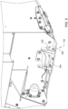
FIG. 4 is a schematic side view of the main frame and the hydraulic system. -
FIG. 5 is a schematic perspective view of a harvester head of the harvester implement showing a gauge shoe. - Those having ordinary skill in the art will recognize that terms such as "above," "below," "upward," "downward," "top," "bottom," etc., are used descriptively for the figures, and do not represent limitations on the scope of the disclosure, as defined by the appended claims. Furthermore, the teachings may be described herein in terms of functional and/or logical block components and/or various processing steps. It should be realized that such block components may be comprised of any number of hardware, software, and/or firmware components configured to perform the specified functions.
- The terms "forward", "rearward", "left", and "right", when used in connection with a moveable implement and/or components thereof are usually determined with reference to the direction of travel during operation, but should not be construed as limiting. The terms "longitudinal" and "transverse" are usually determined with reference to the fore-and-aft direction of the implement relative to the direction of travel during operation, and should also not be construed as limiting.
- Terms of degree, such as "generally", "substantially" or "approximately" are understood by those of ordinary skill to refer to reasonable ranges outside of a given value or orientation, for example, general tolerances or positional relationships associated with manufacturing, assembly, and use of the described embodiments.
- As used herein, "e.g." is utilized to non-exhaustively list examples, and carries the same meaning as alternative illustrative phrases such as "including," "including, but not limited to," and "including without limitation." As used herein, unless otherwise limited or modified, lists with elements that are separated by conjunctive terms (e.g., "and") and that are also preceded by the phrase "one or more of," "at least one of," "at least," or a like phrase, indicate configurations or arrangements that potentially include individual elements of the list, or any combination thereof. For example, "at least one of A, B, and C" and "one or more of A, B, and C" each indicate the possibility of only A, only B, only C, or any combination of two or more of A, B, and C (A and B; A and C; B and C; or A, B, and C). As used herein, the singular forms "a", "an" and "the" are intended to include the plural forms as well, unless the context clearly indicates otherwise. Further, "comprises," "includes," and like phrases are intended to specify the presence of stated features, steps, operations, elements, and/or components, but do not preclude the presence or addition of one or more other features, steps, operations, elements, components, and/or groups thereof.
- Referring to the Figures, wherein like numerals indicate like parts throughout the several views, a harvester implement is generally shown at 20. Referring to
FIG. 1 , the example embodiment of the harvester implement 20 includes, but is not limited to, a self-propelled windrower implement. However, it should be appreciated that the teachings of this disclosure may be applied to machines other than the example windrower implement depicted inFIG. 1 . - Referring to
FIG. 1 , the harvester implement 20 includes amain frame 22, which supports aprime mover 24. Theprime mover 24 may include, but is not limited to, an internal combustion engine, an electric motor, a combination of both, or some other device capable of generating torque to power the harvester implement 20. - The
main frame 22 supports at least oneground engaging devices FIG. 4 ). In the example implementation shown in the Figures and described herein, theground engaging devices front drive wheel 28 and a rightfront drive wheel 30 each mounted to themain frame 22 adjacent aforward end 32 of themain frame 22, and a leftrear caster wheel 34 and a right rear caster wheel (not shown) each attached to themain frame 22 adjacent arearward end 36 of themain frame 22. The leftfront drive wheel 28 and the rightfront drive wheel 30 are rotatable about atransverse axis 38. Thetransverse axis 38 is generally perpendicular to alongitudinal axis 40 of themain frame 22. - As understood by those skilled in the art, the left
front drive wheel 28 and the rightfront drive wheel 30 may be simultaneously rotated in the same rotational direction and at the same rotational speed about thetransverse axis 38 to drive the harvester implement 20 forward or rearward, depending upon the direction of rotation. Additionally, the leftfront drive wheel 28 and the rightfront drive wheel 30 may be rotated in the same rotational direction at different rotational speeds about thetransverse axis 38, or in opposite rotational directions at the same or different rotational speeds about thetransverse axis 38, in order to turn the agricultural vehicle. - As used herein, the term "caster wheel" should be understood to include a wheel that is able to rotate a full three hundred sixty degrees (360°) about a respective generally vertical axis. As such, each of the left
rear caster wheel 34 and the right rear caster wheel are rotatable a full three hundred sixty degrees (360°) about a respective generally vertical axis. The leftrear caster wheel 34 and the right rear caster wheel may be attached to themain frame 22 in a suitable manner. The specific manner in which the leftrear caster wheel 34 and the right rear caster wheel are attached to themain frame 22 is not pertinent to the teachings of this disclosure, are understood by those skilled in the art, and are therefore not described in detail herein. - Referring to
FIGS. 2-4 , the harvester implement 20 includes ahydraulic system 42. Thehydraulic system 42 includes apressure source 44 configured to supply a flow of pressurized hydraulic fluid. Thepressure source 44 may include, but is not limited to, an auxiliary fluid pump that is driven by and coupled to theprime mover 24. Thepressure source 44 draws the hydraulic fluid from atank 46, and circulates the hydraulic fluid through thehydraulic system 42. Thetank 46 receives the hydraulic fluid from thehydraulic system 42, stores the fluid, and supplies the hydraulic fluid to thepressure source 44, e.g., the auxiliary fluid pump. Fluid flow and/or pressure may be used to operate various components of the harvester implement 20, as described in greater detail below. - The
hydraulic system 42 may include atemperature sensor 48 that is operable to detect a temperature of the hydraulic fluid of thehydraulic system 42, and particularly a temperature of the hydraulic fluid in afloat system 50 described in greater detail below. Thetemperature sensor 48 may include, but is not limited to, a thermocouple, a resistive temperature device, a thermistor, an infrared sensor, abimetallic temperature sensor 48, or some other device capable of sensing data related to the temperature of the hydraulic fluid of thehydraulic system 42. - Referring to
FIG. 3 , the harvester implement 20 includes an implementlinkage system 52 attached to themain frame 22. Thelinkage system 52 is moveable relative to themain frame 22. In the implementation shown in the Figures and described herein, the implementlinkage system 52 is attached to themain frame 22 adjacent theforward end 32 of themain frame 22. The implementlinkage system 52 is configured for supporting and attaching aharvester head 54 relative to themain frame 22. In the example implementation shown in the Figures and described herein, theharvester head 54 may include a rotary cutter head, such as shown inFIG. 1 , a draper cutter head, a corn harvester, or some other implement configured for harvesting a crop. It should be appreciated that theharvester head 54 may include a device other than the example rotary cutter head, and that the harvester implement 20 is not limited to the self-propelled windrower implement shown in the figures and desired herein. - Referring to
FIG. 3 , the implementlinkage system 52 includes arockshaft 56 rotatably mounted to themain frame 22 for rotational movement about ashaft axis 58 that extends transverse to thelongitudinal axis 40 of themain frame 22. Alift system 60 includes alift cylinder 62 attached to and interconnecting therockshaft 56 and themain frame 22. Thelift cylinder 62 is operable to rotate therockshaft 56 about theshaft axis 58 in order to raise and lower theharvester head 54 relative to theground surface 26. As such, thelift cylinder 62 is operated to control a vertical height of theharvester head 54 above theground surface 26. In the example implementation described herein, thelift cylinder 62 is a single acting hydraulic cylinder disposed in fluid communication with thehydraulic system 42. As shown inFIG. 2 , alift control valve 64 controls fluid communication between thelift cylinder 62 and thepressure source 44. In other embodiments, thelift cylinder 62 may include a double acting hydraulic cylinder, an electrically actuated linear actuator, or some other device capable of extending and retracting. Thelift cylinder 62 extends in response to fluid pressure and/or flow from thehydraulic system 42 in the usual manner, and is retracted by gravitational forces acting on the implementlinkage system 52 and/or the selectedharvester head 54 attached to the implementlinkage system 52 as understood by those skilled in the art. - Referring to
FIG. 3 , thefloat system 50 interconnects themain frame 22 and thelinkage system 52. The implementlinkage system 52 may further include a left connectingarm 66 and aright connecting arm 68. Theleft connecting arm 66 is rotatably attached to themain frame 22 below therockshaft 56, on a left side of themain frame 22. Aleft linkage 70 is attached to and interconnects theleft connecting arm 66 and therockshaft 56. Thefloat system 50 may include aleft float cylinder 72 attached to and interconnecting themain frame 22 and theleft linkage 70. A respectiveforward end 32 of theleft float cylinder 72 is attached to theleft linkage 70. Theleft float cylinder 72 extends rearward and vertically upward to a respectiverearward end 36 of theleft float cylinder 72, which is attached to themain frame 22. - The
right connecting arm 68 is rotatably attached to themain frame 22 below therockshaft 56, on a right side of themain frame 22. Aright linkage 74 is attached to and interconnects theright connecting arm 68 and therockshaft 56. Thefloat system 50 may include aright float cylinder 76 attached to and interconnecting themain frame 22 and theright linkage 74. A respectiveforward end 32 of theright float cylinder 76 is attached to theright linkage 74. Theright float cylinder 76 extends rearward and vertically upward to a respectiverearward end 36 of theright float cylinder 76, which is attached to themain frame 22. - Referring to
FIG. 2 , thefloat system 50 is disposed in fluid communication with thehydraulic system 42, and includes an internal fluid pressure that is controllable to achieve a ground contact force between theharvester head 54 and theground surface 26. Theleft float cylinder 72 and theright float cylinder 76 are operably controlled via the internal fluid pressure exerted by the hydraulic fluid as is understood by those skilled in the art. - As shown in
FIG. 2 , theleft float cylinder 72 is disposed in fluid communication with aleft accumulator 78. Theleft float cylinder 72 and theleft accumulator 78 cooperate to form a volume. The internal fluid pressure within the volume defined by theleft float cylinder 72 and theleft accumulator 78 may be controlled to provide a resistance against retraction or compression of theleft float cylinder 72. A leftfloat control valve 80 controls fluid communication between theleft float cylinder 72 and thepressure source 44 of thehydraulic system 42. - As shown in
FIG. 2 , theright float cylinder 76 is disposed in fluid communication with aright accumulator 82. Theright float cylinder 76 and theright accumulator 82 cooperate to form a volume. The internal fluid pressure within the volume defined by theright float cylinder 76 and theright accumulator 82 may be controlled to provide a resistance against retraction or compression of theright float cylinder 76. A rightfloat control valve 84 controls fluid communication between theright float cylinder 76 and thepressure source 44 of thehydraulic system 42. Theleft float cylinder 72 and theright float cylinder 76 are each operable to provide a bias or resistance force against upward movement of theleft connecting arm 66 and theright connecting arm 68 respectively. - In the example implementation described herein, the
left float cylinder 72 and theright float cylinder 76 are each single acting hydraulic cylinders disposed in fluid communication with thehydraulic system 42. In other embodiments, theleft float cylinder 72 and theright float cylinder 76 may include a double acting hydraulic cylinder, an air cushion or spring device, or some other device capable of biasing theleft connecting arm 66 and theright connecting arm 68 downward toward theground surface 26. It should be appreciated that in other implementations of the disclosure, thefloat system 50 may include only a single float cylinder disposed in fluid communication with a single accumulator. - Referring to
FIGS. 3 and4 , the implementlinkage system 52 may further include atilt system 86. Thetilt system 86 interconnects thelinkage system 52 and theharvester head 54. Thetilt system 86 may include atilt cylinder 88 that is operable to control a relative tilt angle and/or a relative tilt position between theharvester head 54 and thelinkage system 52. Thetilt cylinder 88 is attached to and interconnects themain frame 22 and theharvester head 54 attached to the implementlinkage system 52. Thetilt cylinder 88 is operable to rotate the selectedharvester head 54 attached to the implementlinkage system 52 relative theground surface 26. More specifically, thetilt cylinder 88 rotates the selectedharvester head 54 about atilt axis 90, which extends transverse to thelongitudinal axis 40 of themain frame 22 and through distal ends of theleft connecting arm 66 and theright connecting arm 68. In the example implementation described herein, thetilt cylinder 88 is a double acting hydraulic cylinder disposed in fluid communication with thehydraulic system 42. Atilt control valve 89 controls fluid communication between thetilt cylinder 88 and thepressure source 44 of thehydraulic system 42. In other embodiments, thetilt cylinder 88 may include a single acting hydraulic cylinder, an electrically actuated linear actuator, or some other device capable of extending and retracting. Thetilt cylinder 88 extends and retracts in response to fluid pressure and/or flow from thehydraulic system 42 in the usual manner as understood by those skilled in the art. - The harvester implement 20 may further include a
tilt position sensor 92. Thetilt position sensor 92 is operable to detect data related to the relative tilt angle and/or relative tilt position between theharvester head 54 and thelinkage system 52. Thetilt position sensor 92 may include, but is not limited to, a linear potentiometer, a rotary potentiometer, an optical sensor, and angular sensor, or some other device capable of detecting data related to the relative position between thelinkage system 52 and theharvester head 54. - The implement
linkage system 52 is controllable between a float operating condition and a fixed height operating condition. When configured for the float operating condition, the implementlinkage system 52 allows theharvester head 54 to vertically track theground surface 26 during horizontal movement of the harvester implement 20 over theground surface 26. Referring toFIG. 2 , when configured for the float operating condition, thelift control valve 64 is closed to block fluid communication between thepressure source 44 and thelift cylinder 62. Areturn valve 94 may be opened to allow fluid communication between thelift cylinder 62 and thetank 46, which allows thelift cylinder 62 to extend and retract freely. Additionally, when the implementlinkage system 52 is configured for the float operating condition, a desired amount of fluid pressure is supplied to theleft float cylinder 72 and theright float cylinder 76 to provide a desired internal fluid pressure to theleft float cylinder 72 and theright float cylinder 76 to resist against upward vertical movement, thereby keeping the selectedharvester head 54 in contact with theground surface 26 while allowing the selectedharvester head 54 to track theground surface 26. The value of the internal fluid pressure supplied to theleft float cylinder 72 and theright float cylinder 76 is proportional to the ground contact force between theharvester head 54 and theground surface 26. A higher internal fluid pressure generates a quicker return downward and a higher ground contact force, whereas a lower internal fluid pressure generates a slower return downward and a lower ground contact force. Aleft pressure sensor 96 may be included to sense and monitor the fluid pressure applied to theleft float cylinder 72. Similarly, aright pressure sensor 98 may be included to sense and monitor the fluid pressure applied to theright float cylinder 76. - Referring to
FIGS. 4 and5 , theharvester head 54 includes at least onegauge shoe 100. Thegauge shoe 100 is positioned to contact theground surface 26 and operable to control a minimum height between theharvester head 54 and theground surface 26. Thegauge shoe 100 may be adjustably attached to theharvester head 54 to set a desired head height above theground surface 26. As such, thegauge shoe 100 may be moved between different vertical positions relative to theharvester head 54 to control the desired head height above theground surface 26. Thegauge shoe 100 is intended to be the portion of theharvester head 54 that contacts theground surface 26 and prevent other components of theharvester head 54 from contacting theground surface 26. Thegauge shoe 100 may include a plate, skid, or other rigid structure that is attached to theharvester head 54 and capable of supporting theharvester head 54 and sliding across theground surface 26. In the implementation described herein, thegauge shoe 100 may include, but is not limited to aleft gauge shoe 100 disposed on the left side of theharvester head 54, adjacent arearward end 36 of theharvester head 54, and aright gauge shoe 100 disposed on the right side of theharvester head 54, adjacent therearward end 36 of theharvester head 54. - The harvester implement 20 may further include a
shoe position sensor 102. Theshoe position sensor 102 is operable to detect data related to a position of thegauge shoe 100 of theharvester head 54 relative to thelinkage system 52. Theshoe position sensor 102 may include, but is not limited to, a linear potentiometer, a rotary potentiometer, an optical sensor, and angular sensor, or some other device capable of detecting data related to the position of thegauge shoe 100 relative to theharvester head 54 and/or thelinkage system 52. In other implementations, the operator of the vehicle may manually enter the position of thegauge shoe 100 viainput 112 into afloat control algorithm 118 described in greater detail below. - Referring to
FIG. 5 , the harvester implement 20 may further include acontact force sensor 104. Thecontact force sensor 104 is operable to detect a current contact force between theharvester head 54 and theground surface 26. Thecontact force sensor 104 may include, but is not limited to, a load cell, an elastic pressure sensor, an electrical transducer, a differential pressure cell, a vacuum pressure sensor, a strain gauge, or some other device capable of detecting data related to the pressure and/or force exerted between thegauge shoe 100 of theharvester head 54 and theground surface 26. In one implementation, thecontact force sensor 104 may include a load cell that is coupled to thegauge shoe 100 of theharvester head 54. The load cell is operable to detect the load applied to thegauge shoe 100 by theground surface 26. - Referring to
FIG. 1 , thecontact force sensor 104 is operable to communicate a communication signal to acommunicator 106. Thecommunicator 106 may include a device capable of communicating a message to an operator. For example, thecommunicator 106 may include, but is not limited to, a touch screen display, a visual display, a speaker, one or more indicator lights, etc. The communication signal is operable to generate an indication of the current contact force between theharvester head 54 and theground surface 26 on thecommunicator 106. In one implementation, thecontact force sensor 104 sends a data signal to acontroller 108, whereby thecontroller 108 then sends the communication signal to thecommunicator 106. - Referring to
FIG. 1 , the harvester implement 20 may further include anoperator station 110, which houses control components of the harvester implement 20. The control components may include, but are not limited to, an output, e.g., thecommunicator 106, and aninput 112. Thecommunicator 106 is operable to convey a message to an operator. Theinput 112 is operable to receive instructions from the operator. In the example implementation described herein, theinput 112 and the output are combined and implemented as a touch screen display. Messages may be communicated to the operator through the display, and data may be entered by the operator by touching the display as is understood by those skilled in the art. It should be appreciated that theinput 112 and the output may differ from the example implementation described herein and may be separate or combined components. For example, thecommunicator 106 may include, but is not limited to, a video only display, an audio speaker, a light board, etc. Theinput 112 may include, but is not limited to, a mouse, a keyboard, a microphone, etc. - The
controller 108 may be disposed in communication the various components of the harvester implement 20 described herein. Thecontroller 108 is operable to at least receive data entry from theinput 112, receive data from sensors, e.g., thetilt position sensor 92, theshoe position sensor 102, thetemperature sensor 48, and/or thecontact force sensor 104, send messages to thecommunicator 106, and control the operation of theleft float cylinder 72 and theright float cylinder 76. While thecontroller 108 is generally described herein as a singular device, it should be appreciated that thecontroller 108 may include multiple devices linked together to share and/or communicate information therebetween. Furthermore, it should be appreciated that all or parts of thecontroller 108 may be located on the harvester implement 20 or located remotely from the harvester implement 20. - The
controller 108 may alternatively be referred to as a head controller, a computing device, a computer, a control unit, a control module, a module, etc. Thecontroller 108 includes aprocessor 114, amemory 116, and all software, hardware, algorithms, connections, sensors, etc., necessary to manage and control the operation of the components of the harvester implement 20 as described herein. As such, a method may be embodied as a program or algorithm operable on thecontroller 108. It should be appreciated that thecontroller 108 may include any device capable of analyzing data from various sensors, comparing data, making decisions, and executing the required tasks. - As used herein, "controller" is intended to be used consistent with how the term is used by a person of skill in the art, and refers to a computing component with processing, memory, and communication capabilities, which is utilized to execute instructions (i.e., stored on the
memory 116 or received via the communication capabilities) to control or communicate with one or more other components. In certain embodiments, thecontroller 108 may be configured to receive input signals in various formats (e.g., hydraulic signals, voltage signals, current signals, CAN messages, optical signals, radio signals), and to output command or communication signals in various formats (e.g., hydraulic signals, voltage signals, current signals, CAN messages, optical signals, radio signals). - The
controller 108 may be in communication with other components on the harvester implement 20, such as hydraulic components, electrical components, and operator inputs within theoperator station 110. Thecontroller 108 may be electrically connected to these other components by a wiring harness such that messages, commands, and electrical power may be transmitted between thecontroller 108 and the other components. Although thecontroller 108 is referenced in the singular, in alternative embodiments the configuration and functionality described herein can be split across multiple devices using techniques known to a person of ordinary skill in the art. - The
controller 108 may be embodied as one or multiple digital computers or host machines each having one or more processors, read only memory (ROM), random access memory (RAM), electrically-programmable read only memory (EPROM), optical drives, magnetic drives, etc., a high-speed clock, analog-to-digital (A/D) circuitry, digital-to-analog (D/A) circuitry, and any required input/output (I/O) circuitry, I/O devices, and communication interfaces, as well as signal conditioning and buffer electronics. - The computer-
readable memory 116 may include any non-transitory/tangible medium which participates in providing data or computer-readable instructions. Thememory 116 may be non-volatile or volatile. Non-volatile media may include, for example, optical or magnetic disks and other persistent memory. Example volatile media may include dynamic random access memory (DRAM), which may constitute a main memory. Other examples of embodiments formemory 116 include a floppy, flexible disk, or hard disk, magnetic tape or other magnetic medium, a CD-ROM, DVD, and/or any other optical medium, as well as other possible memory devices such as flash memory. - The
controller 108 includes the tangible,non-transitory memory 116 on which are recorded computer-executable instructions, including afloat control algorithm 118. Theprocessor 114 of thecontroller 108 is configured for executing thefloat control algorithm 118. Thefloat control algorithm 118 implements a method of controlling the harvester implement 20, described in detail below. - The method of controlling the harvester implement 20 includes the
controller 108 receiving a user defined input. The user defined input commands a desired ground contact force between theharvester head 54 and theground surface 26 while operating in the float operating condition. The user defined input may be entered via an operator via theinput 112, such as but not limited to a touch screen display. For example, the user may enter a desired ground contact force within a range bounded by an allowed minimum ground contact force and an allowed maximum ground contact force, for example, a value between one hundred fifty pounds (150 lbs.) and two hundred fifty pounds (250 lbs.). In the example implementation described herein, the desired ground contact force is the desired force to be transferred between theharvester head 54 and theground surface 26 through each respective one of theleft float cylinder 72 and theright float cylinder 76. In other words, the desired ground contact force is defined for both theleft float cylinder 72 and theright float cylinder 76 separately. In other implementations, the desired ground contact force may be a cumulative force for the float cylinders. - Once the desired ground contact force has been received by the
controller 108, thecontroller 108 may then automatically define an initial value of the internal fluid pressure to achieve the desired ground contact force. As described above, the internal fluid pressure of thefloat system 50, i.e., the internal fluid pressure of theleft float cylinder 72 combined with theleft accumulator 78, and theright float cylinder 76 combined with theright accumulator 82, control the ground contact force between theharvester head 54 and theground surface 26. As such, thecontroller 108 may define, calculate, or estimate the value of the internal fluid pressure of thefloat system 50 required to achieve the desired ground contact force. This defined value of the internal fluid pressure may be defined as the initial internal fluid pressure of thefloat system 50. Once thecontroller 108 has defined the initial internal fluid pressure of thefloat system 50, thecontroller 108 may control thehydraulic system 42 to achieve the initial value of the internal fluid pressure in thefloat system 50, after which, operation of the harvester implement 20 may begin. - During operation of the harvester implement 20, the
controller 108 may monitor one or more operating parameters of theharvester head 54 in order to automatically detect a change in the operating parameter of theharvester head 54 during operation. A change in the operating parameter may result in a change in the reaction of thefloat system 50 to the internal fluid pressure of thefloat system 50. In other words, while the internal fluid pressure of thefloat system 50 may remain constant, a change in the operating parameter may cause the ground contact force to change or vary from the desired ground contact force. - The one or more operating parameter of the
harvester head 54 may include, but is not limited to, one of the tilt position of theharvester head 54 relative to thelinkage system 52, the position of thegauge shoe 100 of theharvester head 54 relative to thelinkage system 52, or the temperature of the hydraulic fluid generating the internal fluid pressure of thefloat system 50. As such, thecontroller 108 may automatically detect a change during operation in one of the tilt position of theharvester head 54 relative to thelinkage system 52, the position of thegauge shoe 100 of theharvester head 54 relative to thelinkage system 52, or the temperature of the hydraulic fluid generating the internal fluid pressure of thefloat system 50. - The
controller 108 may use data received from thetilt position sensor 92 to detect a change in the tile position and/or tilt angle during operation. Thecontroller 108 may use data received from theshoe position sensor 102 to detect a change in the position of thegauge shoe 100 during operation. In other implementations, thecontroller 108 may receive a position input from the operator via theinput 112 defining the position of thegauge shoe 100 to detect or identify a change in the position of thegauge shoe 100. Thecontroller 108 may use data received from thetemperature sensor 48 to detect a change in the temperature of the hydraulic fluid during operation. It should be appreciated that a change in the operating parameter, e.g., a change in the tilt position, the position of thegauge shoe 100, or a change in the temperature of the hydraulic fluid, may change or alter the response of thefloat system 50 to the internal fluid pressure, thereby changing the resultant ground contact force between theharvester head 54 and theground surface 26. - The change in the operating parameter of the
harvester head 54 may be identified or detected by thecontroller 108 to include a deviation between a first data set and a second data set over a period of time that is greater than or less than a defined allowable threshold variation from an initial value of the operating parameter. In other words, the operating parameter may include the initial value of the operating parameter for which theharvester head 54 should operate. A change may be defined when an actual value of the operating parameter, detected by one or more sensors of the harvester implement 20, increases or decreases above or below the initial value of the operating parameter by the defined allowable threshold variation respectively. As such, the defined allowable threshold variation defines a range above and below the initial value of the operating parameter. Actual values outside of this range may be defined as a change in the operating parameter. - Upon detecting and/or identifying a change in the operating parameter, the
controller 108 may then automatically adjust the internal fluid pressure of thefloat system 50. Thecontroller 108 may adjust the internal fluid pressure of thefloat system 50 by re-defining the initial value of the internal fluid pressure to provide or define an adjusted value of the internal fluid pressure. Thecontroller 108 adjusts the internal fluid pressure of thefloat system 50 to a value suitable to maintain the desired ground contact force during operation based on the detected change in the operating parameter of the cutter head during operation. Once thecontroller 108 has defined the adjusted value of the internal fluid pressure of thefloat system 50, thecontroller 108 may then control thehydraulic system 42 to achieve the adjusted value of the internal fluid pressure in thefloat system 50. - By continuously executing the process described herein, the
controller 108 may dynamically change the internal fluid pressure of thefloat system 50 based on the changes in the operating parameter of theharvester head 54 during operation. By dynamically changing the internal fluid pressure of thefloat system 50 in response to the detected changes in the operating parameter, thecontroller 108 may maintain the desired ground contact force as desired, thereby improving operation of theharvester head 54. - The detailed description and the drawings or figures are supportive and descriptive of the disclosure, but the scope of the disclosure is defined solely by the claims. While some of the best modes and other embodiments for carrying out the claimed teachings have been described in detail, various alternative designs and embodiments exist for practicing the disclosure defined in the appended claims.
Claims (14)
- A harvester implement (20) comprising:a main frame (22) supporting at least one ground engaging device (28, 30, 34) and operable to traverse across a ground surface (26);a linkage system (52) attached to the main frame (22) and moveable relative to the main frame (22);a harvester head (54) attached to and supported by the linkage system (52) relative to the main frame (22);a float system (50) interconnecting the main frame (22) and the linkage system (52), wherein the float system (50) includes an internal fluid pressure that is controllable to achieve a ground contact force between the harvester head (54) and the ground surface (26);a controller (108) including a processor (114) and a memory (116) having a float control algorithm (118) stored thereon, wherein the processor (114) is operable to execute the float control algorithm (118) to:receive a user defined input commanding a desired ground contact force;define an initial value of the internal fluid pressure to achieve the desired ground contact force;automatically detect a change in an operating parameter of the harvester head (54) during operation; andautomatically re-define the initial value of the internal fluid pressure to provide an adjusted value of the internal fluid pressure to maintain the desired ground contact force based on the detected change in the operating parameter of the harvester head (54) during operation.
- The harvester implement (20) set forth in claim 1, wherein the operating parameter of the harvester head (54) includes one of a tilt position of the harvester head (54) relative to the linkage system (52), a position of a gauge shoe (100) of the harvester head (54) relative to the linkage system (52), or a temperature of a hydraulic fluid generating the internal fluid pressure of the float system (50).
- The harvester implement (20) set forth in claim 1 or 2, wherein the processor (114) is operable to execute the float control algorithm (118) to automatically detect a change during operation in one of a tilt position of the harvester head (54) relative to the linkage system (52), a position of a gauge shoe (100) of the harvester head (54) relative to the linkage system (52), or a temperature of a hydraulic fluid generating the internal fluid pressure of the float system (50).
- The harvester implement (20) according to at least one of the preceding claims, wherein the float system (50) includes a hydraulic float cylinder (72, 76) operably controlled via the internal fluid pressure exerted by a hydraulic fluid.
- The harvester implement (20) according to at least one of the preceding claims, wherein the float system (50) includes an accumulator (78) disposed in fluid communication with the hydraulic float cylinder (72, 76).
- The harvester implement (20) according to at least one of the preceding claims, further comprising a tilt system (86) interconnecting the linkage system (52) and the harvester head (54), wherein the tilt system (86) includes a tilt cylinder (88) operable to control a tilt angle between the harvester head (54) and the linkage system (52).
- The harvester implement (20) according to at least one of the preceding claims, wherein the harvester head (54) includes a gauge shoe (100) positioned to contact the ground surface (26) and operable to control a minimum height between the harvester head (54) and the ground surface (26).
- The harvester implement (20) according to at least one of the preceding claims, further comprising a tilt position sensor (92) operable to detect a tilt angle between the harvester head (54) and the linkage system (52).
- The harvester implement (20) according to at least one of the preceding claims, further comprising a shoe position sensor (102) operable to detect a position of a gauge shoe (100) of the harvester head (54) relative to the linkage system (52).
- The harvester implement (20) according to at least one of the preceding claims, further comprising a temperature sensor (48) operable to detect a temperature of a hydraulic fluid of the float system (50).
- The harvester implement (20) according to at least one of the preceding claims, further comprising a contact force sensor (104) operable to detect a current contact force between the harvester head (54) and the ground surface (26).
- The harvester implement (20) set forth in claim 11, wherein the contact force sensor (104) is coupled to a gauge shoe (100) of the harvester head (54).
- The harvester implement (20) set forth in claim 11 or 12, wherein the contact force sensor (104) is operable to communicate a communication signal to a communicator (106), wherein the communication signal is operable to generate an indication of the current contact force between the harvester head (54) and the ground surface (26) on the communicator (106).
- The harvester implement (20) according to at least one of the preceding claims, wherein the change in the operating parameter of the harvester head (54) includes a deviation between a first data set and a second data set over a period of time that is greater than or less than a defined allowable threshold variation from an initial value of the operating parameter.
Applications Claiming Priority (1)
| Application Number | Priority Date | Filing Date | Title |
|---|---|---|---|
| US18/473,818 US20250098567A1 (en) | 2023-09-25 | 2023-09-25 | Harvester implement with dynamically adjustable float system |
Publications (1)
| Publication Number | Publication Date |
|---|---|
| EP4527182A1 true EP4527182A1 (en) | 2025-03-26 |
Family
ID=92583169
Family Applications (1)
| Application Number | Title | Priority Date | Filing Date |
|---|---|---|---|
| EP24196572.2A Pending EP4527182A1 (en) | 2023-09-25 | 2024-08-27 | Harvester implement with dynamically adjustable float system |
Country Status (3)
| Country | Link |
|---|---|
| US (1) | US20250098567A1 (en) |
| EP (1) | EP4527182A1 (en) |
| CA (1) | CA3252887A1 (en) |
Citations (5)
| Publication number | Priority date | Publication date | Assignee | Title |
|---|---|---|---|---|
| US20060144028A1 (en) * | 2004-03-31 | 2006-07-06 | Mclean Kenneth W | Independent hydraulic header lift and flotation system |
| US7707811B1 (en) * | 2009-04-15 | 2010-05-04 | Cnh America Llc | Header flotation and lift system with dual mode operation for a plant cutting machine |
| US20210100155A1 (en) * | 2019-10-08 | 2021-04-08 | Deere & Company | Method of adjusting a harvesting header float system based on machine pitch or terrain and system thereof |
| US20220053693A1 (en) * | 2020-08-24 | 2022-02-24 | Cnh Industrial America Llc | Ground pressure feedback sensor system for controlling header float |
| EP3987909A1 (en) * | 2020-10-21 | 2022-04-27 | Deere & Company | Automated header floatation adjustment system for an agricultural machine |
Family Cites Families (11)
| Publication number | Priority date | Publication date | Assignee | Title |
|---|---|---|---|---|
| US6901729B1 (en) * | 2004-03-31 | 2005-06-07 | Cnh America Llc | Header lift system with hydraulic counterweight |
| DE102006032599A1 (en) * | 2006-07-14 | 2008-02-07 | Deere & Company, Moline | Hydraulic arrangement |
| US7520115B2 (en) * | 2006-09-15 | 2009-04-21 | Deere & Company | Header float arm load compensation |
| US8001751B2 (en) * | 2007-09-14 | 2011-08-23 | Cnh America Llc | Method for gradually relieving pressure in a hydraulic system utilizing reverse fluid flow through a pump of the system |
| US7661251B1 (en) * | 2008-08-22 | 2010-02-16 | Deere & Company | Header float system for use with an agricultural windrower or combine |
| DE102010021133A1 (en) * | 2010-05-21 | 2011-11-24 | Claas Selbstfahrende Erntemaschinen Gmbh | Agricultural working machine with header |
| US7971420B1 (en) * | 2010-08-31 | 2011-07-05 | Deere & Company | Draper platform suspension |
| US9198349B2 (en) * | 2013-07-12 | 2015-12-01 | Deere & Company | Articulated harvesting head ground force control circuit |
| US9717180B2 (en) * | 2014-08-08 | 2017-08-01 | Deere & Company | Pressure control for hydraulically actuated agricultural headers |
| US10617059B2 (en) * | 2016-06-21 | 2020-04-14 | Macdon Industries Ltd. | Crop machine with an electronically controlled hydraulic cylinder flotation system |
| US10827677B2 (en) * | 2018-01-04 | 2020-11-10 | CNH Industrial America, LLC | Draper header for harvester providing floatation to gauge wheels |
-
2023
- 2023-09-25 US US18/473,818 patent/US20250098567A1/en active Pending
-
2024
- 2024-08-21 CA CA3252887A patent/CA3252887A1/en active Pending
- 2024-08-27 EP EP24196572.2A patent/EP4527182A1/en active Pending
Patent Citations (5)
| Publication number | Priority date | Publication date | Assignee | Title |
|---|---|---|---|---|
| US20060144028A1 (en) * | 2004-03-31 | 2006-07-06 | Mclean Kenneth W | Independent hydraulic header lift and flotation system |
| US7707811B1 (en) * | 2009-04-15 | 2010-05-04 | Cnh America Llc | Header flotation and lift system with dual mode operation for a plant cutting machine |
| US20210100155A1 (en) * | 2019-10-08 | 2021-04-08 | Deere & Company | Method of adjusting a harvesting header float system based on machine pitch or terrain and system thereof |
| US20220053693A1 (en) * | 2020-08-24 | 2022-02-24 | Cnh Industrial America Llc | Ground pressure feedback sensor system for controlling header float |
| EP3987909A1 (en) * | 2020-10-21 | 2022-04-27 | Deere & Company | Automated header floatation adjustment system for an agricultural machine |
Also Published As
| Publication number | Publication date |
|---|---|
| CA3252887A1 (en) | 2025-06-04 |
| US20250098567A1 (en) | 2025-03-27 |
Similar Documents
| Publication | Publication Date | Title |
|---|---|---|
| EP3987909A1 (en) | Automated header floatation adjustment system for an agricultural machine | |
| EP3987910B1 (en) | Windrower header floatation system having assisted downforce control | |
| US12396394B2 (en) | Header height control for a harvesting head | |
| US20190327893A1 (en) | Header float and skid plate adjustment | |
| AU2018260864A1 (en) | Engine speed control and ground speed control of a hydraulically driven tractor | |
| US11985918B2 (en) | Obstacle detection and field mapping for a work vehicle | |
| US20250098567A1 (en) | Harvester implement with dynamically adjustable float system | |
| US11793099B2 (en) | Harvester implement steering control system to prevent over-running harvester head end during turn | |
| US20250261583A1 (en) | Harvester implement with implement head height determination | |
| US12382848B2 (en) | Pressure to hold or raise the head for a work implement | |
| US20250185542A1 (en) | Windrower implement with merger attachment | |
| US20220117160A1 (en) | Windrower header floatation system having assisted downforce control with downforce return valve | |
| US12000109B2 (en) | Scraper control method | |
| EP4165978B1 (en) | Windrower variable rate header floatation system | |
| US11547049B2 (en) | Windrower variable rate header floatation system | |
| US20250241243A1 (en) | Agricultural Harvester Header Compatibility Control | |
| US20250241242A1 (en) | Agricultural Harvester Header Compatibility Control | |
| EP4000361A1 (en) | Automated implement height or depth control for terrain | |
| US20250327264A1 (en) | Work vehicle attachment service mode | |
| EP4399955A1 (en) | Harvester implement with automated operating mode initialization | |
| JPH1146539A (en) | Working height control device for mobile farm machine |
Legal Events
| Date | Code | Title | Description |
|---|---|---|---|
| PUAI | Public reference made under article 153(3) epc to a published international application that has entered the european phase |
Free format text: ORIGINAL CODE: 0009012 |
|
| STAA | Information on the status of an ep patent application or granted ep patent |
Free format text: STATUS: THE APPLICATION HAS BEEN PUBLISHED |
|
| AK | Designated contracting states |
Kind code of ref document: A1 Designated state(s): AL AT BE BG CH CY CZ DE DK EE ES FI FR GB GR HR HU IE IS IT LI LT LU LV MC ME MK MT NL NO PL PT RO RS SE SI SK SM TR |
|
| STAA | Information on the status of an ep patent application or granted ep patent |
Free format text: STATUS: REQUEST FOR EXAMINATION WAS MADE |
|
| 17P | Request for examination filed |
Effective date: 20250926 |