EP4527171A1 - Systems and methods for detection and assignment of selective control valve couplings - Google Patents
Systems and methods for detection and assignment of selective control valve couplings Download PDFInfo
- Publication number
- EP4527171A1 EP4527171A1 EP24200451.3A EP24200451A EP4527171A1 EP 4527171 A1 EP4527171 A1 EP 4527171A1 EP 24200451 A EP24200451 A EP 24200451A EP 4527171 A1 EP4527171 A1 EP 4527171A1
- Authority
- EP
- European Patent Office
- Prior art keywords
- subsystem
- identifier
- implement
- control valve
- sensor
- Prior art date
- Legal status (The legal status is an assumption and is not a legal conclusion. Google has not performed a legal analysis and makes no representation as to the accuracy of the status listed.)
- Granted
Links
Images




Classifications
-
- A—HUMAN NECESSITIES
- A01—AGRICULTURE; FORESTRY; ANIMAL HUSBANDRY; HUNTING; TRAPPING; FISHING
- A01B—SOIL WORKING IN AGRICULTURE OR FORESTRY; PARTS, DETAILS, OR ACCESSORIES OF AGRICULTURAL MACHINES OR IMPLEMENTS, IN GENERAL
- A01B59/00—Devices specially adapted for connection between animals or tractors and agricultural machines or implements
-
- F—MECHANICAL ENGINEERING; LIGHTING; HEATING; WEAPONS; BLASTING
- F15—FLUID-PRESSURE ACTUATORS; HYDRAULICS OR PNEUMATICS IN GENERAL
- F15B—SYSTEMS ACTING BY MEANS OF FLUIDS IN GENERAL; FLUID-PRESSURE ACTUATORS, e.g. SERVOMOTORS; DETAILS OF FLUID-PRESSURE SYSTEMS, NOT OTHERWISE PROVIDED FOR
- F15B20/00—Safety arrangements for fluid actuator systems; Applications of safety devices in fluid actuator systems; Emergency measures for fluid actuator systems
- F15B20/005—Leakage; Spillage; Hose burst
-
- A—HUMAN NECESSITIES
- A01—AGRICULTURE; FORESTRY; ANIMAL HUSBANDRY; HUNTING; TRAPPING; FISHING
- A01B—SOIL WORKING IN AGRICULTURE OR FORESTRY; PARTS, DETAILS, OR ACCESSORIES OF AGRICULTURAL MACHINES OR IMPLEMENTS, IN GENERAL
- A01B76/00—Parts, details or accessories of agricultural machines or implements, not provided for in groups A01B51/00 - A01B75/00
Definitions
- the present disclosure generally relates to coupling of hydraulic circuits between an agricultural vehicle and an implement, and, more specifically, to automatic detection and assignment of selective control valves for each of a plurality of hydraulic circuits.
- Agricultural machines including, for example, tractors, can be utilized to push, pull, or tow various implements that are configured to perform an agricultural operation(s).
- tractors can be utilized to at least provide a force that propels various implements that can perform an agricultural operation such as, for example, seeding a field, spraying crops, cutting crops, forming windrows, or performing bailing operations, among other agricultural operations.
- the implements used to perform such agricultural operations can have various hydraulically operated subsystems used to perform, as well as control, various operations of the implement.
- the hydraulically operated subsystems of the implement can be fluidly coupled to a hydraulic system of the agricultural vehicle.
- a pump and associated fluid reservoir, among other components, that are part of a hydraulic system of the agricultural vehicle can be fluidly coupled to different subsystems of the implement, thereby becoming part of fluid circuits of subsystems of the implement.
- the present disclosure may comprise one or more of the following features and combinations thereof.
- a method for identifying a fluid connection between a control valve secured to an agricultural vehicle and an implement of an agricultural machine.
- the method can include transmitting a signal containing captured information obtained by a sensor, and identifying, from the transmitted captured information, an identifier coupled to a conduit. Additionally, the method can include retrieving or receiving an identification of at least one of a subsystem or an operation of the implement assigned to the identifier, and detecting, from the captured information, the control valve to which the conduit is fluidly coupled.
- an assignment can be recorded of the control valve detected from the captured information to at least one of the subsystem or the operation assigned to the identifier, and a signal can be transmitted for displaying, on a display unit, an identification of the assignment of the control valve identified from the captured information to at least one of the subsystem or the operation.
- a method for identifying fluid connections between a plurality of control valves secured to an agricultural vehicle and a plurality of subsystems or operations of an implement.
- the method can include identifying, from information captured by one or more sensors, a plurality of identifiers, each identifier of the plurality of identifiers being coupled to a different conduit of a plurality of conduits, each conduit being coupled to a control valve of the plurality of control valves and at least one of a subsystem of a plurality of subsystems or an operation of a plurality of operations of the implement. Further, for each identifier of the plurality of identifiers, an identification can be retrieved or received of at least one of the subsystem or the operation assigned to the identifier.
- the plurality of identifiers can be assigned to a different subsystem of the plurality of subsystems or a different operation of the plurality of operations than at least another identifier of the plurality of identifiers.
- the method can also include identifying, for each identifier, and from the captured information, the control valve of the plurality of control valves that is to be associated with at least one of the identifier or the conduit that is coupled to the identifier, and recording an assignment of the control valve identified from the captured information to at least one of the subsystem or the operation assigned to the identifier.
- one or more signals can be transmitted for displaying on a display unit an identification, for each control valve, of the assignment of the control valve to at least one of the subsystem or the operation.
- a system for identifying a fluid connection between a control valve secured to an agricultural vehicle and an implement.
- the system can include a plurality of identifiers, each identifier of the plurality of identifiers being coupled to a conduit of a plurality of conduits, each conduit of the plurality of conduits configured to be fluidly coupled between a control valve of a plurality of control valves at the agricultural vehicle and a subsystem of a plurality of subsystems of the implement.
- the system can further include at least one sensor positioned to capture information, a display unit, at least one processor, and a memory device coupled with the at least one processor.
- the memory device can include instructions that when executed by the at least one processor can cause the at least one processor to identify, from information captured by the at least one sensor, at least one identifier of the plurality of identifiers, and retrieve or receive, for the at least one identifier, an identification of at least one of the subsystem or an operation of the subsystem assigned to the at least one identifier.
- the memory device can include instructions that when executed by the at least one processor can cause the at least one processor to identify, for each of the at least one identifier, and from the captured information, the control valve of the plurality of control valves that is to be associated with the at least one identifier or the conduit that is coupled to the at least one identifier, and determine an assignment of the control valve identified from the captured information to the at least one of the subsystem or the operation of the subsystem assigned to the at least one identifier.
- the memory device can also include instructions that when executed by the at least one processor can cause the at least one processor to generate one or more signals to display on the display unit an identification of the assignment of the control valve to at least one of the subsystem or the operation of the subsystem.
- references in the specification to "one embodiment,” “an embodiment,” “an illustrative embodiment,” etc., indicate that the embodiment described may include a particular feature, structure, or characteristic, but every embodiment may or may not necessarily include that particular feature, structure, or characteristic. Moreover, such phrases are not necessarily referring to the same embodiment. Further, when a particular feature, structure, or characteristic is described in connection with an embodiment, it is submitted that it is within the knowledge of one skilled in the art to effect such feature, structure, or characteristic in connection with other embodiments whether or not explicitly described.
- items included in a list in the form of "at least one A, B, and C” can mean (A); (B); (C); (A and B); (A and C); (B and C); or (A, B, and C).
- items listed in the form of "at least one of A, B, or C” can mean (A); (B); (C); (A and B); (A and C); (B and C); or (A, B, and C).
- an exemplary agricultural machine 100 is depicted that includes an agricultural vehicle 102, such as, for example, a tractor, that is coupled to an implement 104.
- the implement 104 is embodied as, or otherwise includes, a baler, such as, for example, a square or round baler, among other types of balers.
- a variety of different agricultural machines or implements can be utilized as the agricultural machine 100, including, but not limited to, seeders, forage harvesters, and sprayers, among others.
- Figure 1 illustrates the agricultural machine 100 as including an implement 104 that is towed by the agricultural vehicle 102
- the implement 104 can comprise an agricultural device, equipment, or tool that can be pushed or pulled by the agricultural vehicle 102.
- the implement 104 can be coupled to the agricultural vehicle 102 in a variety of different manners, including, but not limited to, via a hitch, among other couplings.
- the agricultural vehicle 102 can include one or more ground engagement bodies 106a, 106b, such as, for example, wheels, tires, or tracks, as well as various combinations thereof, among other types of ground engagement bodies.
- the implement 104 can also include can also include one or more ground engagement bodies 108a, 108b, such as, for example, wheels, tires, or tracks, as well as various combinations thereof, among other types of ground engagement bodies.
- FIG. 1 illustrates such engagement bodies 106a, 106b, 108a, 108b on one side of the agricultural vehicle 102 and the implement 104, respectively
- similar engagement bodies 106a, 106b, 108a, 108b can additionally be located on the opposing side of the corresponding agricultural vehicle 102 and implement 104, among other locations.
- the ground engagement bodies 106a, 106b, 108a, 108b are positioned to contact the adjacent ground surface 110, and are used in connection with propulsion of the agricultural machine 100 in at least the forward operating or travelling direction 112 along the ground surface 110. Additionally, an angular orientation of at least some of the ground engagement bodies 106a, 106b, 108a, 108b relative to the ground surface 112 can be adjusted in connection with steering or guiding the direction of travel of the agricultural machine 100.
- the exemplary agricultural machine 100 is to perform an agricultural operation subsequent to another agricultural operation that may have been perform by utilizing a different agricultural implement or agricultural machine.
- a prior agricultural operation may have been performed relating to cutting a crop plant so as to form a windrow.
- the illustrated agricultural machine 100 shown in Figure 1 can utilize an implement 104 in the form of a baler to either or both collect or bale at least a portion of the cut crop material that was contained in a windrow.
- various other types of agricultural operation(s) can be performed by agricultural machine 100.
- the implement 104 coupled to the agricultural vehicle 102 can be a sprayer, or, alternatively, can be utilized for planting crop seeds, among other agricultural operations. Further, such different agricultural operations may involve changing the implement 104 that is coupled to the agricultural vehicle 102, or, alternatively, involve one or more other agricultural implements 104 that is/are coupled to one or more other agricultural vehicles 102.
- the agricultural machine 100 is capable of traversing the field, collecting crop material from the windrow from the ground surface 110 of the associated field, and processing the collected crop material to form crop bales 114.
- the implement 104 of the agricultural machine 100 can include one or more mechanisms that cooperate to collect and deliver crop material from the windrow into a baling or compression chamber 116 of the implement 104.
- the implement 104 of the agricultural machine 100 can include a pick-up mechanism 118 that is configured to gather crop material from the windrow and feed it, via a loading mechanism 120, toward the compression chamber 116 of a compression system 122.
- the pick-up mechanism 118 can include devices such as tines, forks, augers, conveyors, baffles, cutters, pre-cutter assemblies, the like, or any combination thereof.
- the loading mechanism 120 can include devices such as projections, tines, forks, knives, the like, or any combination thereof.
- the baling or compression system 122 can include at least one baler or compression mechanism or chamber that is capable of compressing and/or shaping the collected crop material from the windrow into one or more crop bales 114.
- the compression system 122 can be powered by a drive unit such as, for example, a motor or engine.
- rotational power from a power source such as, for example, a drive unit of the agricultural machine 100, can be provided or transmitted to the compression system 122 via use of a power-takeoff (PTO) shaft that is coupled to the power source.
- PTO power-takeoff
- the PTO shaft can be directly or indirectly coupled to the compression system 122.
- Crop bales 114 formed by the agricultural machine 100 can be ejected from a rear opening 124 of the compression chamber 116 tailgate or rear door or gate 126 of the implement 104.
- the gate 126 can be, for example, in a closed, or lowered position so as to be generally adjacent to the compression chamber 116 at least while collected crop material is being compressed by the compression system 122 within the compression chamber 116.
- the gate 126 can also be displaced to a raised, or open position, as shown in Figure 1 , so that a compressed bale 114 can be released from the baler 104.
- the agricultural vehicle 102 can include a hydraulic system that can be utilized to operate various subsystems of the agricultural vehicle 102, including, for example, either or both steering and braking systems of the agricultural vehicle 102, among subsystems, devices or components.
- the hydraulic system can include, for example, a pump 182 ( Figure 3 ) and one or more fluid reservoirs, among other components.
- the pump 182 can be utilized to at least assist in circulating hydraulic fluid about the hydraulic system of at least the agricultural vehicle 102, and can also be configured to at least assist in pressurizing the hydraulic fluid within the hydraulic system.
- the hydraulic system of the agricultural vehicle 102 can include a plurality of electrohydraulic selective control valves (SCVs) 130a-d, as illustrated, for example, in at least Figures 2-5 . While the SCVs 130a-d can be positioned at a variety of locations about the agricultural vehicle 102, according to the illustrated embodiment, a plurality of individual SVCs 130a-d can be position together, including, for example, and in a stack arrangement, to provide a selective control valve connector manifold 132, as seen, for example, in Figures 1 and 2 . While Figures 2-5 illustrate a selective control valve connector manifold 132 having four SCVs 130a-d, the number of SCVs 130a-d can vary, and, according to certain embodiments, the number of SCVs 130a-d can also be adjustable.
- SCVs electrohydraulic selective control valves
- the SCV 130a-d can include a fluid outlet 134 through which hydraulic fluid flows out from the associated SCV 130a-d, and thus out of the hydraulic system of the agricultural vehicle 102.
- hydraulic fluid can flow, for example, via operation of the pump 182, through an opened SCV 130a-d in connection with being supplied for an associated portion of the fluid circuit 138a-d located at the implement 104.
- Each SCV 130a-d can also include a fluid inlet 136 for the return of hydraulic fluid from the portion of the fluid circuit 138a-d located at the implement 104 to the hydraulic system of the agricultural vehicle 102.
- each fluid outlet 134 and fluid inlet 136 can include a coupling 140, such as, for example, a threaded or quick disconnect style coupling, among others, that is configured for coupling to a conduit 146a-d (collectively referred to as conduit 146) that is used in the delivery of hydraulic fluid to, or from, the implement 104.
- each coupling 140 can be selectively covered by a cover 142.
- the cover 142 can be configured and positioned to selectively extend over an opening 144 of the adjacent coupling 140 so as to at least assist in preventing debris from entering into the SCV 130a-d, and thus into the hydraulic system of the agricultural vehicle 102.
- a cover 142 when a particular SCV 130a, 130c is not in use, a cover 142 can be positioned over the corresponding openings 144 of the couplings 140.
- the covers 142 over the openings 144 of the adjacent couplings 140 for those particular SCVs 130b, 130d can be displaced, such as, for example, rotated, away from the coupling 140 so as to not interfere with an attachment of a conduit 146 to that coupling 140.
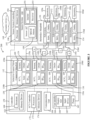
- FIG. 3 illustrates a simplified block diagram of an exemplary electrohydraulic selective control valve (SCV) detection system 200.
- SCV selective control valve
- a corresponding fluid circuit 138a-d can be completed that fluidly couples the hydraulic system of the agricultural vehicle 102 to a portion of the fluid circuit 138a-d provided by, and used to at least partially operate, the corresponding subsystem 150a-d of the implement 104.
- hydraulic fluid can pass from the fluid outlet 134 of an SCV 130a-d at the agricultural vehicle 102, and thus from the hydraulic system of the agricultural vehicle 102, through a conduit 146, and enter a fluid inlet 154 of an associated subsystem 150a-d of the implement 104.
- each fluid circuit 138a-d can be configured such that the hydraulic fluid can pass from the implement 104 through a fluid outlet 152 of the subsystem 150a-d, through another, or return, conduit 146, and through a fluid inlet 136 of the associated SCV 130a-d so as to return to the hydraulic system of the agricultural vehicle 102.
- Figure 3 illustrates the fluid inlets 154 and fluid outlets 152 of the implement 104 being arranged together in connection with a hydraulics manifold 156, at least some, if not all, of the fluid inlets 136 and fluid outlets 138 of the subsystems 150 of the implement 104 may, or may not, be generally positioned at, or around, the location of the fluid inlets 154 and fluid outlets 152 of other subsystems 150a-d.
- Figure 3 illustrates a single conduit connection between the SCVs 130a-d and the associated subsystems 150a-d.
- each of the illustrated conduits 146 can comprise a first conduit that can accommodate a flow of hydraulic fluid from the SCV 130a-d to the associated subsystem 150, and another conduit for the return of hydraulic fluid from the subsystem 150a-d to the corresponding SCV 130a-d.
- the agricultural vehicle 102 can, over time, be coupled to different implements 104 that may have different numbers of subsystems 150a-d.
- the conduits 146a-d to which the agricultural vehicle 102 are coupled can change for different implements 104.
- the conduits 146 to which the agricultural vehicle 102 is coupled can change.
- the particular subsystem 150a-d to which an SCV 130a-d can change.
- the example shown in Figure 3 illustrates the first SCV 130a being fluidly coupled to the second subsystem 150b, the second SCV 130b being fluidly coupled to the first subsystem 150a, the third SCV 130c being fluidly coupled to the fourth subsystem 150d, and the fourth SCV 130d being fluidly coupled to the third subsystem 150c.
- embodiments of the subject disclosure can ease the burden, and minimize errors, with respect to the detection and assignment of which particular SCV 130a-d is fluidly coupled to which particular subsystem 150a-d o the implement 104, if any.
- the SCV detection system 200 can include a controller 158 of the agricultural vehicle 102 that can include, or can be associated with, one or more processors 160 that can follow instructions, including control instructions, contained with, or are part of, one or more memory devices 162, including, for example, a non-transitory machine-readable medium.
- Various operations, steps or algorithms as described in connection with the work vehicle controller 158 can be embodied directly in hardware, in a computer program product such as a software module executed by the processor 160, or in a combination of the two.
- the computer program product can reside in RAM memory, flash memory, ROM memory, EPROM memory, EEPROM memory, registers, hard disk, a removable disk, as well as combinations thereof, among any other form of computer-readable medium.
- the controller 158 can be a single controller having all of the described functionality, or it can include multiple controllers wherein the described functionality is distributed among the multiple controllers.
- the controller 158 can be coupled to one or more user interfaces 164 of the agricultural vehicle 102 that can be utilized by the human operator to input instructions that can be received by at least the controller 158.
- the user interface 164 can take a variety of forms, including, for example, be or include a monitor, screen, touch screen, keyboard, keypad, mouse, switch, joystick, button, or steering wheel, as well as any combination thereof, among other types of controls or user inputs for operating the agricultural vehicle 102, including operation of the engine, hydraulic cylinders, and the like.
- Figures 3 and 7 illustrate the user interface 164 as comprising a display unit 184 or other outputs from the system such as indicator lights, audible alerts, and the like, and an input device 185, such as for example, a joystick, among other input devices.
- a display unit 184 or other outputs from the system such as indicator lights, audible alerts, and the like
- an input device 185 such as for example, a joystick, among other input devices.
- the user interface 164 can be positioned in an operator cab 128 ( Figure 1 ) of the agricultural vehicle 102.
- Such an onboard user interface 164 can be coupled to the controller 158 via, for example, a controller area network (CAN) bus arrangement or other equivalent forms of electrical and/or electro-mechanical signal transmission.
- CAN controller area network
- Another form of the user interface 164 can take the form of a display unit that is generated on a remote (i.e., not onboard) computing device, which can display outputs, such as, for example, status indications and/or otherwise enable user interaction such as the providing of inputs to, or for, the agricultural vehicle 102.
- data transmission between, for example, the controller 158 and the user interface 164 can utilize a communication unit 166 of the agricultural vehicle 102, and can take the form of a wired and/or wireless communications system(s) and associated components and protocol(s).
- the communication unit 166 can support or provide communications between the controller 158 of the agricultural vehicle 102 and external systems or devices, and/or support or provide communication interface with respect to internal components of the agricultural vehicle 102.
- the communications unit 166 can include wireless communication system components (e.g., via cellular, Wi-Fi, Bluetooth or the like) and/or can include one or more wired communications terminals, such as universal serial bus ports, among others.
- the communication unit 166 can be communicatively coupled to a network, including, for example, via internet, cellular, and/or Wi-Fi networks.
- connection to the network can facilitate an exchange of information, including information between the agricultural machine 100 and a secondary device 168, including a central database, a remote database, such as, for example, a cloud based server or database, or other agricultural or work machines, as well as combinations thereof.
- a secondary device 168 including a central database, a remote database, such as, for example, a cloud based server or database, or other agricultural or work machines, as well as combinations thereof.
- the SCV detection system 200 can also include one or more, if not a plurality, of SCVs 130a-d.
- Each SCV 130a-d can be utilized to selectively control the flow of hydraulic fluid within the associated fluid circuit 138a-d, and thereby at least assist in controlling the operation (generally identified in Figure 3 as Operations 1-4 ) of each associated subsystem (generally identified in Figure 3 as Susbsytems 1-4 ).
- Such control of hydraulic fluid flow can be utilized to control operation of one or more actuators of the fluid circuit 138a-d or associated subsystem 150a-d, including, for example, hydraulically actuated cylinders, among other hydraulic actuators.
- the selective control valve connector manifold 132 is illustrated as having four SCVs 130a-d, with each SCV 130a-d being individually fluidly coupled to the fluid inlets 136 and fluid outlets 134 of four subsystems 150a-d of the implement 104, and thus being part of a different fluid circuit 138a-d.
- a first SCV 130a is fluidly coupled to a second subsystem 150b of the implement 104
- a second SCV 130b is fluidly coupled to a first subsystem 150a of the implement 104
- a third SCV 130c is fluidly coupled to a fourth subsystem 150d of the implement 104
- a fourth SCV 130d is fluidly coupled to third subsystem 150c of the implement 104.
- the particular subsystem 150a-d to which each SCV 130a-d is fluidly coupled can vary, and in some instances, can be based on the order in which an operator attaches the various associated conduits 146 that may already be attached to a subsystem 130a-d of the implement 104.
- Figure 3 illustrates each SCV 130a-d being coupled to a subsystem 150a-d if the implement 104, in certain instances only a portion of the SCVs 130a-d maybe utilized. For instance, in certain situations, the implement 104 may have a number of subsystems 150a-d for such fluid connections that are less than the number of SCVs 130a-d that are available at the agricultural vehicle 102.
- the operation of the each SCV 130a-d can be controller using the controller 158 of the agricultural vehicle 102. Additionally, or alternatively, according to certain embodiments, operation of the SCVs 130a-d can be at least partially controlled by an SCV controller 170 that has one or more processors 172 and memory devices 174 that can be similar to the above-discussed processor(s) 160 and memory device(s) 162 of the controller 158. One or both of the controller 158 and the SCV controller 170 can be used to control certain operations or settings of the SCVs 130a-d, including, for example, flow rates, among other functions.
- controller 158 and the SCV controller 170 can be utilized in at least connection with the operation of each SCV 130a-d, including with respect to the opening or closing of the SCVs 130a-d so as to control whether hydraulic fluid flows, or does not flow, from the hydraulic system of the agricultural vehicle 102 and to/from an associated subsystem 150a-d of the implement 104, as discussed below.
- either or both the controller 158 and the SCV controller 170 can generate a signal that is received by a solenoid of an SCV 130a-d that can be used to individually control whether the associated SCV 130a-d is to be displaced to, or maintained, in an open position that can accommodate flow of hydraulic fluid through the SCV 130a-d, or be in a closed position that, at least temporarily, prevents the passage of hydraulic fluid through the SCV 130a-d.
- the SCV detection system 200 can include a sensor system controller 190 having at least one processor 192 and a memory device(s) 194 that can have configurations that are similar to those discussed above with respect to at least the processor(s) 160 and memory device(s) 162, respectively, of the controller 158 of the agricultural vehicle 102. Additionally, while the sensor system controller 190 is illustrated in Figure 3 as being located at the implement 104, according to other embodiments, the sensor system controller 190 can be located at the agricultural vehicle 102, or be located at a combination thereof.
- the sensor system controller 190 can be communicatively coupled to either or both the controller 158 of the agricultural vehicle 102 and the SCV controller 170 in a variety of different manners, including, but not limited to, a wired or wireless connection, as well as combinations thereof.
- communications between the sensor system controller 190, or other portions of the implement 104, and either or both the controller 158 and the SCV controller 170 can utilize a CAN bus arrangement, among other forms of connections or communication protocols.
- Figure 3 illustrates a separate sensor system controller 190, the sensor system controller 190 can be part of any other controller 158, 170 of the agricultural vehicle 102 or implement 104.
- the SCV detection system 200 further includes a sensor system 186 that is configured to capture, or otherwise obtain, information that can be used to identify the SCV 130a-d to which each subsystem 150a-d of the implement 104 is fluidly coupled, as discussed below.
- a sensor system 186 that is configured to capture, or otherwise obtain, information that can be used to identify the SCV 130a-d to which each subsystem 150a-d of the implement 104 is fluidly coupled, as discussed below.
- Figure 3 illustrates an example in which a plurality of subsystems 150a-d that perform different operations (e.g. Operations 1-4 ) are fluidly coupled to a plurality of the SCVs 130a-d by various different conduits 146.
- Figure 3 depicts a single conduit 164 connection between the SCVs 130a-d and the associated subsystem 150a-d.
- each of the conduits 146 illustrated in Figure 3 can comprise a first conduit 146a that can accommodate a flow of hydraulic fluid from the SCV 130a-d to the associated subsystem 150, and another conduit for the return of hydraulic fluid from the subsystem 150a-d to the corresponding SCV 130a-d.
- the agricultural vehicle 102 can, at different times, be couple to different implements 104 that may have different numbers of subsystems 150a-d.
- the particular conduits 146a-d to which the agricultural vehicle 102 and SCVs 130a-d are coupled can change for different implements 104.
- the sensor system 186 can include one or more sensors 187 that can be utilized in the detection or identification of the particular SCV 130a-d a particular conduit 164v is coupled, and thus at least assist in the assignment of the identified SCV 130a-d to a particular subsystem 150a-d or associated operation associated with that conduit(s) 146.
- the sensor 187 can comprise one or more optical sensors 188, including, but not limited to, stereo depth cameras, stereo sensors, RGBD (red, green, blue, depth) cameras, three-dimensional sensors, three-dimensional cameras, structural light sensors, or light detection ranging sensors, as well as combinations thereof, among other types of sensors.
- the optical sensor 188 can capture information in one or more images or videos of an identifier (I 1 , I 2 , I 3 , I 4 ) of at least some, if not all, of the conduits 146a-d.
- the identifiers (I 1 , I 2 , I 3 , I 4 ) can be in a variety of formats, including, for example, text, numeric, symbols or colors, among other visual identifiers, as well as combinations thereof.
- the memory device 194 of the sensor system controller 190, or other memory or database can have a record or other recording that indicates which particular subsystem of the implement is associated with each identifier (I 1 , I 2 , I 3 , I 4 ).
- the identifiers (I 1 , I 2 , I 3 , I 4 ) can be attached or otherwise coupled to a conduit 146 at a location at which, when the conduit 146 is coupled to an SCV 130a-d of the SCV connector manifold 132, at least a portion of the identifier (I 1 , I 2 , I 3 , I 4 ) can be detected by the sensor system 186.
- the identifier can be, or be on, a tag or collar 196 that is coupled to the conduit 146 at, around, or by, a connector body 198 of the conduit 146.
- each identifier (I 1 , I 2 , I 3 , I 4 ) is a different color on a collar 196 of each of the conduits 146a-d.
- the optical sensor 188 can be coupled to the implement 104 at a location at which the optical sensor 188 can capture information, such as, for example, in the form of one or more images or videos, that includes information the can indicate, or be used to derive, the color of one or more, if not all, of identifiers (I 1 , I 2 , I 3 , I 4 ).
- the sensor system controller 190 including the associated processor(s) 192, can be configured to evaluate such captured information from the optical sensor 188 on a pixel level, or based on a collection or area(s) of pixels, among other bases for evaluation.
- Such an evaluation can be based, for example, at least in part, on either or both a color or level of light present or not present in an area(s) or pixels in the captured information.
- such object detection can be utilized to detect, based on the order of the stacked arrangement of the SCVs 130a-d, among other features, the particular SCV 130a-d to which the conduit 146a-d having the identified identifier (I 1 , I 2 , I 3 , I 4 ) is attached.
- the captured information from the optical sensor 188 can include depth information, or other distance related information, that can be utilized by the sensor system controller 190 to identify which particular SCV 130a-d the conduit 146 having the identified identifier (I 1 , I 2 , I 3 , I 4 ) is coupled.
- the memory device 194 of the sensor system controller 190 can include information relating to the distances between the different SCVs 130a-d and the sensor 187 that can be utilized in determining the particular SCV 130a-d the conduit 146a-d having the identified identifier (I 1 , I 2 , I 3 , I 4 ) is coupled.
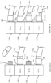
- Figure 4 provides an example in which a first conduit 146a is identified by a first identifier (Ii), and a third identifier is identified by a third identifier (I 3 ).
- each identifier (I 1 , I 2 , I 3 , I 4 ) can, with respect to the implement 104, provide an indication of the particular subsystem 150a-d to which the conduit 146a-d associated with that identifier (I 1 , I 2 , I 3 , I 4 ) is fluidly coupled.
- Such assignments of the identifiers (I 1 , I 2 , I 3 , I 4 ) can be preset, including be part of a default setting, or be a setting that can be adjusted by an operator.
- a sensor 187 such as, for example, an optical sensor 188, can capture information in one or more images or videos obtained by the sensor 187.
- the captured information in this example, can provide information that the sensor system controller 190 can analyze to identify the first identifier (Ii).
- the sensor system controller 190 can identify, from the captured information provided by the sensor 187, the color of the first identifier (I 1 ).
- the sensor system controller 190 can also retrieve or access information indicating the subsystem 150a-d, or associated operation 180a-d, of the implement 104 that is associated with the first identifier (Ii), and, moreover, the subsystem 150a-d to which the conduit 146a having the first identifier (Ii) is, or is to be, fluidly coupled.
- the sensor system controller 190 can also analyze the captured information with respect to performing object detection, wherein the sensor system controller 190 can analyze the captured information to determine which particular SCV 130a-d the conduit 146 of the identified identifier (Ii) is attached.
- object detection can utilize known depth information, among other information, regarding the location, relative positions or spacing of the SCVs 130a-d to identify each particular SCV 130a-d in the captured information.
- the sensor system controller 190 can identify that the conduit 140a associated with the first identifier (Ii) is coupled to the second SCV 130b. With information regarding the particular subsystem 150a associated with the first identifier (I 1 ), the sensor system controller 190 can identify that the second SCV 130b is being used in connection with the operation 180a of the first subsystem 150a.
- the first identifier (I 1 ) can be associated with a subsystem 150b that controls the raising, or opening, and lowering, or closing, of the gate 126 of an implement 104 in the form of a baler.
- the sensor system controller 190 can automatically identify for the operator that the second SCV 130b is to be operated to control the raising and lowering of the gate 126.
- the captured information provided from the sensor 187 can also be used by at least the sensor system controller 190 to identify the third identifier (I 3 ) in connection with recognizing the associated third conduit 146c is coupled to the fourth SCV 130d.
- the sensor system controller 190 can retrieve or receive information indicating that the operation of the particular subsystem 150c of the implement 104 that is coupled to the third conduit 146c can, at least partially, be controller via operation of the fourth SCV 130d.
- the third subsystem 150c can relate to one or more hydraulically actuated actuators that can be utilized to adjust a position or height of the pick-up mechanism 118 relative to the ground surface 110 or a windrow.
- information obtained by the sensor system 186 can be used to generate information to an operator of the agricultural machine 100 that the operation of the third SCV 130c can be used to control or adjust the position of the pickup mechanism 118.
- Such automatic recognition, and assignment, of the particular SCV 130a-d at the agricultural vehicle 102 that is fluidly coupled to a particular subsystem 150a-d, or associated operation 180a-d, of the implement 104 can eliminate the need for an operator to manually determine, remember, and correctly input any identification of assignments of each of the different SCVs 130a-d to each of the different subsystems 150a-d or operations 180a-d of the implement 104. Further, such automatic detection and assigned of the particular SCV 130a-d from the plurality of SCVs 130a-d that is to be assigned to each subsystem 150a-d or operations 180a-d can further improve the safety of the operation of the work machine 100 and implement 104.
- the first subsystem 150a of the implement 104 is fluidly coupled, and at least partially controlled by, the operation of the second SCV 130b, and is discussed above as being related to functions involving the raising and lowering of the gate 126.
- an operator may mistakenly assign the second SCV 130b as being coupled to, or used to operate, the third subsystem 150c, which in this example is instead configured to adjust the height of the pick-up mechanism 118.
- the operator in the event the operator seeks to adjust the height pick-up mechanism 118 via operation of at least the second SCV 130b, the operator would instead inadvertently cause the gate 126 to either be raised or lowered, which can create a hazardous situation, particularly if an individual is positioned by or behind the gate 126.
- the automatic detection of which subsystem 150a-d or associated operation 180a-d is fluidly coupled to a particular SCV 130a-d, and the automatic assignment of such subsystems 150a-d and their associated operation 180a-d via use of the identified SCV 130a-d can advert such potentially hazardous situations, as well as further reduce the burden on the operator to correctly remember and make such assignments.
- Figure 5 illustrates another example of one or more sensors 187 of the sensor system 186 being used to provide information to identify an identifier (I 1 , I 2 , I 3 , I 4 ) provided on, or otherwise coupled to, a conduit 146, as well to identify the particular SCV 130a-d to which the conduit 146a-d associated with the identifier (I 1 , I 2 , I 3 , I 4 ) is coupled.
- Figure 5 provides an example of a sensor 187 being a plurality of proximity sensors 189a-d, such as, for example, an inductive proximity sensors.
- the inductive proximity sensors 189a-d can be coupled to the agricultural vehicle 102, and more specifically, to one or more of the SCVs 130a-d.
- the identifiers I 1 , I 2 , I 3 , I 4
- the identifiers can be an electrically conductive material, including, for example, a magnetic material, that can generate eddy currents that can impact a magnetic field generated by the inductive proximity sensors 189a-d.
- each identifier (I 1 , I 2 , I 3 , I 4 ) can have a different configuration, including, for example, shape, size, or thickness, as well as combinations thereof, among other differences, that can differently influence the extent each identifier (I 1 , I 2 , I 3 , I 4 ) has on magnetic losses that are attributed to eddy currents.
- the sensor system controller 190 can include, or retrieve, information, that can identify anticipated ranges of detected magnetic losses anticipated to be associated with each of the different identifiers (I 1 , I 2 , I 3 , I 4 ).
- Such differences in the extent of anticipated magnetic losses can assist the sensor system controller 190 with identifying the particular identifier (I 1 , I 2 , I 3 , I 4 ) that is positioned by an inductive proximity sensor 189a-d of a particular SCV 130a-d.
- Figure 5 illustrates an example in which a first identifier (Ii) has a generally oval cross-sectional shape, a second identifier (I 2 ) has a triangular cross-sectional shape, and third and fourth identifiers (I 3 , I 4 ) have generally square or rectangular cross-sectional shapes, wherein the third identifier (I 3 ) has a size, such as, for example, a thickness and width, that is greater than the corresponding sizes of the fourth identifier (I 4 ).
- the anticipated magnetic losses, or ranges thereof, due to eddy currents for each of the identifiers (I 1 , I 2 , I 3 , I 4 ) can be predetermined or anticipated and stored, or otherwise retrievable by the sensor system controller 190, and can be used to distinguish information detected by the inductive proximity sensors 189a-d.
- information or readings of the magnetic losses detected by an inductive proximity sensor 189c of the third SCV 130 can be communicated to the sensor system controller 190.
- the sensor system controller 190 can then compare such information with anticipated or predetermined magnetic loss information to identify the corresponding identifier, which in this example, is the first identifier (Ii).
- the SCV detection system 200 can identify the particular subsystem 150a-d or operation 180a-d to which the third SCV 130c is fluidly coupled.
- a similar process can also be utilized for one or more of the other SCVs 130a, 130b, 130d to also automatically identify and assigned a particular subsystem 150a-d, or associated operation 180a-d, of the implement 104 to each SCV 130a-d.
- Figures 4 and 5 provide examples of sensors 187 that can be utilized by the SCV detection system 200, and which can be located at either, or both, the agricultural vehicle 102 or the implement 104, a variety of other sensors can also be utilized.
- the sensor 187 can include one or more emitters or readers 191 and one or more receivers or tags 193, including, but not limited to, readers 191 and tags 193 that can be utilized with passive radio-frequency identification systems, among other types of sensors.
- the tags 193 can be located on one or more of the conduits 146, and the receivers 193 can be positioned at or around the SCVs 130a-d.
- identifiers (I 1 , I 2 , I 3 , I 4 ) being predesignated or assigned to a particular subsystem 150a-d or operation 180a-d.
- identifiers (I 1 , I 2 , I 3 , I 4 ) are used in connection with the automatic detection and assignment of a particular SCV 130a-d to a subsystem 150a-d
- a similar approach can be utilized to determine the specific subsystem 150a-d to which a particular identifier (I 1 , I 2 , I 3 , I 4 ), or associated conduit 146a-d, is to be assigned.
- the sensor system 186 can also be configured to detect the particular identifier (I 1 , I 2 , I 3 , I 4 ) for the conduit 146a-d that is coupled to a connector(s) of a particular subsystem(s) 150a-d. Using such information, the sensor system controller 190, among other components of the SCV detection system 200, can automatically assign, and record, a particular identifier (I 1 , I 2 , I 3 , I 4 ) being associated with either or both a specific subsystem 150a-d or operation 180a-d.
- the particular identifier I 1 , I 2 , I 3 , I 4
- the sensor system controller 190 can automatically assign that SCV 130a-d to the identified subsystem 150a-d or operation 180a-d, and vice versa.
- Figure 6 illustrates an exemplary method 600 for identifying an SCV 130a-d that is fluidly coupled to a subsystem 150a-d of an implement 104, as well as assigning the identified SCV 130a-d for selective control of an operation 180a-d of the subsystem 150a-d.
- the method 600 is described below in the context of being carried out by the illustrated exemplary SCV detection system 200. However, it should be appreciated that method 600 can likewise be carried out by any of the other described implementations, as well as variations thereof. Further, the method 600 corresponds to, or is otherwise associated with, performance of the blocks described below in the illustrative sequence of Figure 6 . It should be appreciated, however, that the method 600 can be performed in one or more sequences different from the illustrative sequence. Additionally, one or more of the blocks mentioned below may not be performed, and the method 600 can include steps or processes other than those discussed below.
- a conduit 146 can be fluidly coupled to a subsystem 150a-d of the implement 104.
- a connector body 198 of a supply line of the conduit 146 can be coupled to a fluid inlet 154 of a subsystem 154a-d
- a connector body 198 of an outlet line of the conduit 146 can be coupled to a fluid outlet 152 of that subsystem 150a-d.
- At least one of the supply line and the outlet line of the conduit 146 can include an identifier (I 1 , I 2 , I 3 , I 4 ) that can be used in connection with the identification of the SCV 130a-d to which the conduit 146 is coupled, as well as an assignment of that SCV 130a-d to a subsystem 150a-d or the associated operation 180a-d of the subsystem 150a-d, as previously discussed.
- the identifier (I 1 , I 2 , I 3 , I 4 ) to be utilized in detecting a fluid connection with either or both a particular subsystem 150a-d or corresponding operation 180a-d can be recorded.
- the subsystem 150a-d to which the conduit 146 is connected, or the associated identifier (I 1 , I 2 , I 3 , I 4 ) to be identified as being associated with a connection to that subsystem 150a-d or operation 180a-d can be automatically detected and recorded in a manner similar to the manners discussed above in which the particular SCV 130a-d connected to the conduit 146, or the identifier (I 1 , I 2 , I 3 , I 4 ) associated with that connection to the SCV 130a-d, is detected.
- the conduit 146 can also be fluidly coupled to an SCV 130a-d at the agricultural vehicle 102.
- a connector body 198 of the supply line of the conduit 146 can be coupled to a coupling 140 for a fluid outlet 134 of the SCV 130a, and a connector body 198 of the return line of the conduit 146 can be coupled to a coupling 140 of a fluid inlet 136 of the SCV 130a-d.
- the sensor system 186 can be utilized to capture information that the sensor system controller 190 can utilize at block 610 to identify the particular identifier (I 1 , I 2 , I 3 , I 4 ) associated with the conduit 146 that was attached at block 606. For example, as previously discussed, the sensor system controller 190 can evaluate the captured information on a pixel level so as to obtain information that can be used to identified the particular identifier (I 1 , I 2 , I 3 , I 4 ) associated with the conduit 146 that has been connected to the SCV 130a-d.
- the sensor system controller 190 can utilize captured information to identify a color associated with the identifier (I 1 , I 2 , I 3 , I 4 ), among other information, including, but not limited to, a size or shape of the identifier (I 1 , I 2 , I 3 , I 4 ) or other alphanumeric, numeric, or graphic information, among other indicators, provided by the identifier (I 1 , I 2 , I 3 , I 4 ).
- the sensor system controller 190 can also utilize the captured information in connection with objection detection capabilities of the sensor system controller 190. Moreover, the sensor system controller 190 can utilize the captured information to determine the particular SCV 130a-d to which the conduit 146a-d associated with the identified identifier (I 1 , I 2 , I 3 , I 4 ) is coupled. Again, such object detection can be performed in a variety of different manners, including, for example, based on a distance of the SCV 130a-d from the sensor 187, or spatial relationship among the various SCVs 130a-d, among other manners of object detection.
- blocks 602 through 614 are discussed above with respect to identification of one identifier (I 1 , I 2 , I 3 , I 4 ), an associated SCV 130a-d, and a particular subsystem 150a-d or operation 180a-d, the method at blocks 602 through 614 can be performed, or repeated, for a plurality of identifiers (I 1 , I 2 , I 3 , I 4 ), conduits 146a-d, SCVs 130a-d and subsystems 150a-d or operations 180a-d.
- blocks 602 through 614 can be performed with respect to identifying the particular subsystems 150a-d or operations 180a-d that are to be operated for each of four different SCVs 130a-d.
- the information captured by the sensor 187 such as, for example, the same image, collection of images, or video, can be utilized to identify, for a plurality, if not all, of the SCVs 130a-d, the corresponding subsystem 150a-d or operation 180a-d that is fluidly coupled to that SCV 130a-d.
- additional or different captured information including, for example, different images, video, or proximity information can be used for one or more of the SCVs 130a-d to determine the particular subsystem 150a-d or operation 180a-d to which that SCV 130a-d is fluidly coupled.
- an identification for an operator of the particular subsystem 150a-d or operation 180a-d to which each SCV 130a-d is fluidly coupled can be created or populated.
- Figure 3 illustrates an example in which a first SCV 130a is fluidly coupled to a second subsystem 150b of the implement 104, a second SCV 130b is fluidly coupled to a first subsystem 150a of the implement 104, a third SCV 130c is fluidly coupled to a fourth subsystem 150d of the implement 104, and a fourth SCV 130d is fluidly coupled to third subsystem 150c of the implement 104.
- An identification of such connections of the SCVs 130a-d to the subsystems 150a-d can be populated at block 618.
- such a population identifying which SCVs 130a-d are connected to which particular subsystems 150a-d or operations 180a-d can be displayed on a graphical user interface (GUI) 202 that is shown in a display on a display unit 184 control panel in the operator cab 128.
- GUI graphical user interface
- each subsystem 150a-d, or the associated operation 180a-d, and the SCV 130a-d that has been identified as being connected to, or otherwise assigned, to that subsystem 150a-d or operation 180a-d can be shown in a separate icon 165a-d on the GUI 202.
- the icons 165a-d shown in Figure 7 user the terms “Subsystem” and “Operation”, the subsystem 150a-d or operation 180a-d can be represented in each of the different icons 165a-d in different manners, including, for example, with textual descriptions, graphics, or images, as well as combinations thereof.
- the associated icon 165a-d can include a graphical image representing the movement of a gate.
- the particular SCV 130a-d associated with that subsystem 150a-d or operation 180a-d, as identified, for example, at block 614 can also be shown in the icons 165a-d on the GUI 202.
- the operator of the agricultural machine 100 can be notified that the SCV 130a-d and subsystem 150a-d or operation 180a-d assignments have been populated, including, for example, via visual or audible notification from the user interface 164.
- the operator can then decide at block 622 whether to accept, or override, the SCV 130a-d assignments identified by the SCV detection system 200 at block 614.
- the first icon 165a shown in Figure 7 indicates that the SCV detection system 200 has identified the first subsystem 150a-d or operation 180a-d as being coupled, or assigned, to the second SCV 130b, and that the SCV detection system 200 has also identified the second subsystem 150a-d or operation 180a-d as being coupled, or assigned, to the first SCV 130a.
- the operator can be given an opportunity to issue a command, such as, for example, via the use of the user interface 164 to select an icon 165f on the GUI 202, indicating the operator's intention to override one or more of the identified SCV 130a-d assignments.
- the operator can be given an opportunity to communicate to the controller 158, among other controllers 158, 190, that the operator is overriding at least some of the identified assignments, as well as proceed with changing the assignments.
- the operator can make such adjustments. For example, referencing Figure 7 , the operator can utilize the user interface 164 to indicate that the operator is going to override, or adjust, at least some of the SCV 130a-d assignments made by the SCV detection system 200.
- the operator could, via generating a signal(s) through use of the user interface 164, adjust the SCV 130a-d assignments such that the first subsystem 150a-d or operation 180a-d is to be operated using the first SCV 130a, and instead of the second, SCV 130b, and the second subsystem 150a-d or operation 180a-d is to be operated using the second SCV 130b, and instead of the first SCV 130a.
- Such commands from the user interface 164 can then, in this example, be received by the controller 158, 170, 190 to change which particular SCV 130a, 130b is operating the first and second subsystem 150a, 159b or the associated operations 180a, 180b, respectively.
- the operator can enable use of the SCVs 130a-d with the assigned subsystems 150a-d or operations 180a-d, such as, for example, using the user interface 164 to select an enablement or acknowledgement icon 165e on the GUI 202.
- the operator can select a particular icon(s) 164a-d shown on the display unit 184, such as, for example, via use of the user interface 164, to cause the associated operation 180a-d of the SCV 130a-d assigned to that particular subsystem 150a-d/operation 180a-d.
- the operator can select a particular icon 165a-d with respect to allowing, maintaining, or stopping a flow of hydraulic fluid through the corresponding SCV 130a-d.
- control of fluid flow through each particular SCV 130a-d can be used to control the associated operation of at least hydraulic actuators of the corresponding assigned subsystem 150a-d, and thereby control the operation 180a-d of the subsystem 150a-d.
- the sensor system 186 can also be utilized to monitor at least certain aspects of the fluid circuits 138a-d associated with each SCV 130a-d. For example, according to certain embodiments, information captured by the sensor system 186 can be analyzed by the sensor system controller 190, among other controllers 158, 170, to determine whether hydraulic fluid is, or is not, leaking from any connections between the conduits 146 and the associated SCVs 130a-d.
- captured information from the sensors 187 can be utilized to detect whether hydraulic fluid is leaking from a connection between a coupling of the SCV 130a-d and the connector body 198 of the associated conduit 146, or whether the integrity of the SCV 130a-d or conduit 146 has been compromised in a manner that may be resulting in a leakage of hydraulic fluid from the associated fluid circuit 138a-d.
- the sensor system controller 190 can examine information captured by the sensor 187 in connection with determining whether the captured information provides an indication of a leakage of hydraulic fluid, among other potential problems involving the operation 180a-d of the SCVs 130a-d, conduits 146, and associated fluid circuits 138a-d.
- the sensor system controller 190 can generate a signal to provide a notification of the leakage or other problem(s) to the user interface 164 or GUI 202.
- a notification, or alarm can be communicated to the operator in a variety of different manners, including, for example, via a visual warning message or icon 165g or an audible alert communicated to the operator that can be communicated to the operator via the display unit 184 or other portion of the user interface 164.
- the sensor system 186 can also be utilized to obtain information regarding a variety of other operations relating to the agricultural machine 100.
- the sensor system 186 can capture information, such as, for example, from one or more images or videos obtained via use of the optical sensor 188, that can provide information regarding a windrow.
- the optical sensor 188 can be positioned, or, alternatively, can be selectively adjustable, with respect to at least the area(s) from which the sensor 187 captures information so as to capture information relating to at least portions of the window that the baler is, or will be, collecting cut crop material.
- the sensor system controller 190 using the captured information that was obtained at block 634, the sensor system controller 190, among other controllers 158, 170, can, at block 636, analyze the captured information to derive information regarding features or characteristics of the windrow.
- Such information derived at block 636 can include, for example, information regarding a position, orientation, width, vertical height, or density, as well as combinations thereof, among other information, regarding the windrow.
- the information derived at block 636 can then be used by a controller 158 to adjust an operation 180a-d of the agricultural machine including, for example, an operation 180a-d of the associated agricultural vehicle 102 or implement 104.
- information regarding the vertical height or density of the windrow can be utilized to adjust a height of the pick-up mechanism 118 of the implement 104, the direction at which a steering system guides the movement of the agricultural vehicle 102, a speed at which the agricultural vehicle 102 travels, or a position of the agricultural machine 100, as well as combinations thereof, among other adjustments in the operation of the agricultural machine 100.
Landscapes
- Life Sciences & Earth Sciences (AREA)
- Engineering & Computer Science (AREA)
- Mechanical Engineering (AREA)
- Soil Sciences (AREA)
- Environmental Sciences (AREA)
- Chemical & Material Sciences (AREA)
- Analytical Chemistry (AREA)
- Physics & Mathematics (AREA)
- Fluid Mechanics (AREA)
- General Engineering & Computer Science (AREA)
- Zoology (AREA)
- Management, Administration, Business Operations System, And Electronic Commerce (AREA)
Abstract
Description
- The present disclosure generally relates to coupling of hydraulic circuits between an agricultural vehicle and an implement, and, more specifically, to automatic detection and assignment of selective control valves for each of a plurality of hydraulic circuits.
- Agricultural machines, including, for example, tractors, can be utilized to push, pull, or tow various implements that are configured to perform an agricultural operation(s). For example, tractors can be utilized to at least provide a force that propels various implements that can perform an agricultural operation such as, for example, seeding a field, spraying crops, cutting crops, forming windrows, or performing bailing operations, among other agricultural operations.
- The implements used to perform such agricultural operations can have various hydraulically operated subsystems used to perform, as well as control, various operations of the implement. With at least certain types of implements, the hydraulically operated subsystems of the implement can be fluidly coupled to a hydraulic system of the agricultural vehicle. With such agricultural machines, a pump and associated fluid reservoir, among other components, that are part of a hydraulic system of the agricultural vehicle can be fluidly coupled to different subsystems of the implement, thereby becoming part of fluid circuits of subsystems of the implement.
- The present disclosure may comprise one or more of the following features and combinations thereof.
- In one embodiment of the present disclosure, a method is provide for identifying a fluid connection between a control valve secured to an agricultural vehicle and an implement of an agricultural machine. The method can include transmitting a signal containing captured information obtained by a sensor, and identifying, from the transmitted captured information, an identifier coupled to a conduit. Additionally, the method can include retrieving or receiving an identification of at least one of a subsystem or an operation of the implement assigned to the identifier, and detecting, from the captured information, the control valve to which the conduit is fluidly coupled. Further, an assignment can be recorded of the control valve detected from the captured information to at least one of the subsystem or the operation assigned to the identifier, and a signal can be transmitted for displaying, on a display unit, an identification of the assignment of the control valve identified from the captured information to at least one of the subsystem or the operation.
- In another embodiment, a method is provided for identifying fluid connections between a plurality of control valves secured to an agricultural vehicle and a plurality of subsystems or operations of an implement. The method can include identifying, from information captured by one or more sensors, a plurality of identifiers, each identifier of the plurality of identifiers being coupled to a different conduit of a plurality of conduits, each conduit being coupled to a control valve of the plurality of control valves and at least one of a subsystem of a plurality of subsystems or an operation of a plurality of operations of the implement. Further, for each identifier of the plurality of identifiers, an identification can be retrieved or received of at least one of the subsystem or the operation assigned to the identifier. Additionally, at least some of the plurality of identifiers can be assigned to a different subsystem of the plurality of subsystems or a different operation of the plurality of operations than at least another identifier of the plurality of identifiers. The method can also include identifying, for each identifier, and from the captured information, the control valve of the plurality of control valves that is to be associated with at least one of the identifier or the conduit that is coupled to the identifier, and recording an assignment of the control valve identified from the captured information to at least one of the subsystem or the operation assigned to the identifier. Further, one or more signals can be transmitted for displaying on a display unit an identification, for each control valve, of the assignment of the control valve to at least one of the subsystem or the operation.
- In a further embodiment of the present disclosure, a system is provided for identifying a fluid connection between a control valve secured to an agricultural vehicle and an implement. The system can include a plurality of identifiers, each identifier of the plurality of identifiers being coupled to a conduit of a plurality of conduits, each conduit of the plurality of conduits configured to be fluidly coupled between a control valve of a plurality of control valves at the agricultural vehicle and a subsystem of a plurality of subsystems of the implement. The system can further include at least one sensor positioned to capture information, a display unit, at least one processor, and a memory device coupled with the at least one processor. The memory device can include instructions that when executed by the at least one processor can cause the at least one processor to identify, from information captured by the at least one sensor, at least one identifier of the plurality of identifiers, and retrieve or receive, for the at least one identifier, an identification of at least one of the subsystem or an operation of the subsystem assigned to the at least one identifier. Additionally, the memory device can include instructions that when executed by the at least one processor can cause the at least one processor to identify, for each of the at least one identifier, and from the captured information, the control valve of the plurality of control valves that is to be associated with the at least one identifier or the conduit that is coupled to the at least one identifier, and determine an assignment of the control valve identified from the captured information to the at least one of the subsystem or the operation of the subsystem assigned to the at least one identifier. The memory device can also include instructions that when executed by the at least one processor can cause the at least one processor to generate one or more signals to display on the display unit an identification of the assignment of the control valve to at least one of the subsystem or the operation of the subsystem.
- These and other features of the present disclosure will become more apparent from the following description of the illustrative embodiments.
- The disclosure contained herein is illustrated by way of example and not by way of limitation in the accompanying Figures. For simplicity and clarity of illustration, elements illustrated in the Figures are not necessarily drawn to scale. For example, the dimensions of some elements may be exaggerated relative to other elements for clarity. Further, where considered appropriate, reference labels have been repeated among the Figures to indicate corresponding or analogous elements.
-
Figure 1 illustrates a side perspective view of an exemplary agricultural machine having an agricultural vehicle in the form of a tractor and an agricultural implement in the form of a baler. -
Figure 2 illustrates a front side view of an exemplary selective control valve connector manifold having a plurality of individual electrohydraulic selective control valves (SCVs) either in a covered condition or an uncovered condition. -
Figure 3 illustrates a simplified block diagram of an exemplary electrohydraulic selective control valve (SCV) detection system. -
Figures 4 and 5 illustrate side views of embodiments of the selective control valve connector manifold without protective covers and in which at least some of the SCVs are coupled to conduits that may each be fluidly coupled to one or more subsystems of the agricultural implement. -
Figure 6 illustrates an exemplary method for controlling operation of an SCV detection system. -
Figure 7 illustrates an exemplary control panel displaying on a graphical user interface shown on a display unit at least information populated by the exemplary SCV detection system identifying assignments of SCVs to particular subsystems or operations of the implement. - Corresponding reference numerals are used to indicate corresponding parts throughout the several views.
- While the concepts of the present disclosure are susceptible to various modifications and alternative forms, specific embodiments thereof have been shown by way of example in the drawings and will be described herein in detail. It should be understood, however, that there is no intent to limit the concepts of the present disclosure to the particular forms disclosed, but on the contrary, the intention is to cover all modifications, equivalents, and alternatives consistent with the present disclosure and the appended claims.
- References in the specification to "one embodiment," "an embodiment," "an illustrative embodiment," etc., indicate that the embodiment described may include a particular feature, structure, or characteristic, but every embodiment may or may not necessarily include that particular feature, structure, or characteristic. Moreover, such phrases are not necessarily referring to the same embodiment. Further, when a particular feature, structure, or characteristic is described in connection with an embodiment, it is submitted that it is within the knowledge of one skilled in the art to effect such feature, structure, or characteristic in connection with other embodiments whether or not explicitly described. Additionally, it should be appreciated that items included in a list in the form of "at least one A, B, and C" can mean (A); (B); (C); (A and B); (A and C); (B and C); or (A, B, and C). Similarly, items listed in the form of "at least one of A, B, or C" can mean (A); (B); (C); (A and B); (A and C); (B and C); or (A, B, and C).
- In the drawings, some structural or method features may be shown in specific arrangements and/or orderings. However, it should be appreciated that such specific arrangements and/or orderings may not be required. Rather, in some embodiments, such features may be arranged in a different manner and/or order than shown in the illustrative Figures. Additionally, the inclusion of a structural or method feature in a particular Figure is not meant to imply that such feature is required in all embodiments and, in some embodiments, may not be included or may be combined with other features.
- A number of features described below may be illustrated in the drawings in phantom. Depiction of certain features in phantom is intended to convey that those features may be hidden or present in one or more embodiments, while not necessarily present in other embodiments. Additionally, in the one or more embodiments in which those features may be present, illustration of the features in phantom is intended to convey that the features may have location(s) and/or position(s) different from the locations(s) and/or position(s) shown.
- The embodiments of the present disclosure described below are not intended to be exhaustive or to limit the disclosure to the precise forms in the following detailed description. Rather, the embodiments are chosen and described so that others skilled in the art may appreciate and understand the principles and practices of the present disclosure.
- Referring now to
Figure 1 , an exemplaryagricultural machine 100 is depicted that includes anagricultural vehicle 102, such as, for example, a tractor, that is coupled to animplement 104. Moreover, in the illustrated embodiment, theimplement 104 is embodied as, or otherwise includes, a baler, such as, for example, a square or round baler, among other types of balers. However, a variety of different agricultural machines or implements can be utilized as theagricultural machine 100, including, but not limited to, seeders, forage harvesters, and sprayers, among others. Additionally, whileFigure 1 illustrates theagricultural machine 100 as including animplement 104 that is towed by theagricultural vehicle 102, according to certain embodiments, theimplement 104 can comprise an agricultural device, equipment, or tool that can be pushed or pulled by theagricultural vehicle 102. Further, theimplement 104 can be coupled to theagricultural vehicle 102 in a variety of different manners, including, but not limited to, via a hitch, among other couplings. - The
agricultural vehicle 102 can include one or moreground engagement bodies implement 104 can also include can also include one or moreground engagement bodies Figure 1 illustratessuch engagement bodies agricultural vehicle 102 and theimplement 104, respectively,similar engagement bodies agricultural vehicle 102 and implement 104, among other locations. Theground engagement bodies adjacent ground surface 110, and are used in connection with propulsion of theagricultural machine 100 in at least the forward operating or travellingdirection 112 along theground surface 110. Additionally, an angular orientation of at least some of theground engagement bodies ground surface 112 can be adjusted in connection with steering or guiding the direction of travel of theagricultural machine 100. - According to the illustrated embodiments, the exemplary
agricultural machine 100 is to perform an agricultural operation subsequent to another agricultural operation that may have been perform by utilizing a different agricultural implement or agricultural machine. For instance, in the illustrated example, a prior agricultural operation may have been performed relating to cutting a crop plant so as to form a windrow. In such an example, the illustratedagricultural machine 100 shown inFigure 1 can utilize an implement 104 in the form of a baler to either or both collect or bale at least a portion of the cut crop material that was contained in a windrow. However, various other types of agricultural operation(s) can be performed byagricultural machine 100. For example, according to certain embodiments, the implement 104 coupled to theagricultural vehicle 102 can be a sprayer, or, alternatively, can be utilized for planting crop seeds, among other agricultural operations. Further, such different agricultural operations may involve changing the implement 104 that is coupled to theagricultural vehicle 102, or, alternatively, involve one or more otheragricultural implements 104 that is/are coupled to one or more otheragricultural vehicles 102. - In the illustrated example in which the implement 104 is a baler, the
agricultural machine 100 is capable of traversing the field, collecting crop material from the windrow from theground surface 110 of the associated field, and processing the collected crop material to formcrop bales 114. Accordingly, in the exemplary embodiment, the implement 104 of theagricultural machine 100 can include one or more mechanisms that cooperate to collect and deliver crop material from the windrow into a baling orcompression chamber 116 of the implement 104. For example, the implement 104 of theagricultural machine 100 can include a pick-upmechanism 118 that is configured to gather crop material from the windrow and feed it, via aloading mechanism 120, toward thecompression chamber 116 of acompression system 122. The pick-upmechanism 118 can include devices such as tines, forks, augers, conveyors, baffles, cutters, pre-cutter assemblies, the like, or any combination thereof. Theloading mechanism 120 can include devices such as projections, tines, forks, knives, the like, or any combination thereof. - The baling or
compression system 122 can include at least one baler or compression mechanism or chamber that is capable of compressing and/or shaping the collected crop material from the windrow into one ormore crop bales 114. Thecompression system 122 can be powered by a drive unit such as, for example, a motor or engine. For example, rotational power from a power source such as, for example, a drive unit of theagricultural machine 100, can be provided or transmitted to thecompression system 122 via use of a power-takeoff (PTO) shaft that is coupled to the power source. The PTO shaft can be directly or indirectly coupled to thecompression system 122.Crop bales 114 formed by theagricultural machine 100 can be ejected from arear opening 124 of thecompression chamber 116 tailgate or rear door orgate 126 of the implement 104. Thus, thegate 126 can be, for example, in a closed, or lowered position so as to be generally adjacent to thecompression chamber 116 at least while collected crop material is being compressed by thecompression system 122 within thecompression chamber 116. Thegate 126 can also be displaced to a raised, or open position, as shown inFigure 1 , so that acompressed bale 114 can be released from thebaler 104. - The
agricultural vehicle 102 can include a hydraulic system that can be utilized to operate various subsystems of theagricultural vehicle 102, including, for example, either or both steering and braking systems of theagricultural vehicle 102, among subsystems, devices or components. The hydraulic system can include, for example, a pump 182 (Figure 3 ) and one or more fluid reservoirs, among other components. Thepump 182 can be utilized to at least assist in circulating hydraulic fluid about the hydraulic system of at least theagricultural vehicle 102, and can also be configured to at least assist in pressurizing the hydraulic fluid within the hydraulic system. - The hydraulic system of the
agricultural vehicle 102 can include a plurality of electrohydraulic selective control valves (SCVs) 130a-d, as illustrated, for example, in at leastFigures 2-5 . While theSCVs 130a-d can be positioned at a variety of locations about theagricultural vehicle 102, according to the illustrated embodiment, a plurality ofindividual SVCs 130a-d can be position together, including, for example, and in a stack arrangement, to provide a selective controlvalve connector manifold 132, as seen, for example, inFigures 1 and2 . WhileFigures 2-5 illustrate a selective controlvalve connector manifold 132 having fourSCVs 130a-d, the number of SCVs 130a-d can vary, and, according to certain embodiments, the number of SCVs 130a-d can also be adjustable. - As seen in
Figures 2-5 , according to certain embodiments, for eachSCV 130a-d, theSCV 130a-d can include afluid outlet 134 through which hydraulic fluid flows out from the associatedSCV 130a-d, and thus out of the hydraulic system of theagricultural vehicle 102. For example, such hydraulic fluid can flow, for example, via operation of thepump 182, through an openedSCV 130a-d in connection with being supplied for an associated portion of thefluid circuit 138a-d located at the implement 104. EachSCV 130a-d can also include afluid inlet 136 for the return of hydraulic fluid from the portion of thefluid circuit 138a-d located at the implement 104 to the hydraulic system of theagricultural vehicle 102. Further, eachfluid outlet 134 andfluid inlet 136 can include acoupling 140, such as, for example, a threaded or quick disconnect style coupling, among others, that is configured for coupling to aconduit 146a-d (collectively referred to as conduit 146) that is used in the delivery of hydraulic fluid to, or from, the implement 104. Additionally, according to certain embodiments, eachcoupling 140 can be selectively covered by acover 142. Thecover 142 can be configured and positioned to selectively extend over anopening 144 of theadjacent coupling 140 so as to at least assist in preventing debris from entering into theSCV 130a-d, and thus into the hydraulic system of theagricultural vehicle 102. Thus, for example, referencingFigure 2 , when aparticular SCV cover 142 can be positioned over the correspondingopenings 144 of thecouplings 140. In such an example, when aparticular SCV covers 142 over theopenings 144 of theadjacent couplings 140 for those particular SCVs 130b, 130d can be displaced, such as, for example, rotated, away from thecoupling 140 so as to not interfere with an attachment of aconduit 146 to thatcoupling 140. -
Figure 3 illustrates a simplified block diagram of an exemplary electrohydraulic selective control valve (SCV)detection system 200. As illustrated by at leastFigure 3 , eachSCV 130a-d can individually be fluidly coupled to, via one ormore conduits 146, asubsystem 150a-d of the implement 104, and thus be fluidly coupled to a corresponding portion of afluid circuit 138a-d associated with than particular subsystem 150. Accordingly, when anSCV 130a-d is fluidly coupled to an agricultural implement 104, a correspondingfluid circuit 138a-d can be completed that fluidly couples the hydraulic system of theagricultural vehicle 102 to a portion of thefluid circuit 138a-d provided by, and used to at least partially operate, the corresponding subsystem 150a-d of the implement 104. For example, hydraulic fluid can pass from thefluid outlet 134 of anSCV 130a-d at theagricultural vehicle 102, and thus from the hydraulic system of theagricultural vehicle 102, through aconduit 146, and enter afluid inlet 154 of an associatedsubsystem 150a-d of the implement 104. Similarly, eachfluid circuit 138a-d can be configured such that the hydraulic fluid can pass from the implement 104 through afluid outlet 152 of the subsystem 150a-d, through another, or return,conduit 146, and through afluid inlet 136 of the associatedSCV 130a-d so as to return to the hydraulic system of theagricultural vehicle 102. WhileFigure 3 illustrates thefluid inlets 154 andfluid outlets 152 of the implement 104 being arranged together in connection with ahydraulics manifold 156, at least some, if not all, of thefluid inlets 136 and fluid outlets 138 of the subsystems 150 of the implement 104 may, or may not, be generally positioned at, or around, the location of thefluid inlets 154 andfluid outlets 152 ofother subsystems 150a-d. - For at least purposes of illustration,
Figure 3 illustrates a single conduit connection between theSCVs 130a-d and the associatedsubsystems 150a-d. However, as previously discussed, each of the illustratedconduits 146 can comprise a first conduit that can accommodate a flow of hydraulic fluid from theSCV 130a-d to the associated subsystem 150, and another conduit for the return of hydraulic fluid from thesubsystem 150a-d to the correspondingSCV 130a-d. - The
agricultural vehicle 102 can, over time, be coupled todifferent implements 104 that may have different numbers ofsubsystems 150a-d. Thus theconduits 146a-d to which theagricultural vehicle 102 are coupled can change fordifferent implements 104. In such situations, theconduits 146 to which theagricultural vehicle 102 is coupled can change. With such disconnection and reconnection of the SCVs 130a-d to thevarious subsystems 150a-d ofdifferent implements 104, theparticular subsystem 150a-d to which anSCV 130a-d can change. Thus, whileFigure 3 and the below discussion utilizes terms like "first" and "second", among other terms, with respect to identifying aparticular SCV 130a-d or subsystem 150a-d, the "first"SCV 130a does not necessarily need to be coupled to the "first"subsystem 150a. Similarly, the "second", "third", and "fourth"SCVs 130b-d do not necessarily need to be coupled to a "second", "third", and "fourth"subsystem 150b-c, respectively, let alone be coupled to anysubsystem 150a-d. Thus, for instance, the example shown inFigure 3 illustrates thefirst SCV 130a being fluidly coupled to thesecond subsystem 150b, thesecond SCV 130b being fluidly coupled to thefirst subsystem 150a, thethird SCV 130c being fluidly coupled to thefourth subsystem 150d, and thefourth SCV 130d being fluidly coupled to thethird subsystem 150c. As discussed below, embodiments of the subject disclosure can ease the burden, and minimize errors, with respect to the detection and assignment of whichparticular SCV 130a-d is fluidly coupled to which particular subsystem 150a-d o the implement 104, if any. - As seen in
Figure 3 , theSCV detection system 200 can include acontroller 158 of theagricultural vehicle 102 that can include, or can be associated with, one ormore processors 160 that can follow instructions, including control instructions, contained with, or are part of, one ormore memory devices 162, including, for example, a non-transitory machine-readable medium. Various operations, steps or algorithms as described in connection with thework vehicle controller 158 can be embodied directly in hardware, in a computer program product such as a software module executed by theprocessor 160, or in a combination of the two. The computer program product can reside in RAM memory, flash memory, ROM memory, EPROM memory, EEPROM memory, registers, hard disk, a removable disk, as well as combinations thereof, among any other form of computer-readable medium. Further, thecontroller 158 can be a single controller having all of the described functionality, or it can include multiple controllers wherein the described functionality is distributed among the multiple controllers. - The
controller 158 can be coupled to one ormore user interfaces 164 of theagricultural vehicle 102 that can be utilized by the human operator to input instructions that can be received by at least thecontroller 158. Theuser interface 164 can take a variety of forms, including, for example, be or include a monitor, screen, touch screen, keyboard, keypad, mouse, switch, joystick, button, or steering wheel, as well as any combination thereof, among other types of controls or user inputs for operating theagricultural vehicle 102, including operation of the engine, hydraulic cylinders, and the like. For example, for at least purposes of illustration,Figures 3 and7 illustrate theuser interface 164 as comprising adisplay unit 184 or other outputs from the system such as indicator lights, audible alerts, and the like, and aninput device 185, such as for example, a joystick, among other input devices. - According to certain embodiments, the
user interface 164 can be positioned in an operator cab 128 (Figure 1 ) of theagricultural vehicle 102. Such anonboard user interface 164 can be coupled to thecontroller 158 via, for example, a controller area network (CAN) bus arrangement or other equivalent forms of electrical and/or electro-mechanical signal transmission. Another form of theuser interface 164 can take the form of a display unit that is generated on a remote (i.e., not onboard) computing device, which can display outputs, such as, for example, status indications and/or otherwise enable user interaction such as the providing of inputs to, or for, theagricultural vehicle 102. In the context of aremote user interface 164, data transmission between, for example, thecontroller 158 and theuser interface 164 can utilize acommunication unit 166 of theagricultural vehicle 102, and can take the form of a wired and/or wireless communications system(s) and associated components and protocol(s). - The
communication unit 166 can support or provide communications between thecontroller 158 of theagricultural vehicle 102 and external systems or devices, and/or support or provide communication interface with respect to internal components of theagricultural vehicle 102. Thecommunications unit 166 can include wireless communication system components (e.g., via cellular, Wi-Fi, Bluetooth or the like) and/or can include one or more wired communications terminals, such as universal serial bus ports, among others. According to certain embodiments, thecommunication unit 166 can be communicatively coupled to a network, including, for example, via internet, cellular, and/or Wi-Fi networks. Such connection to the network can facilitate an exchange of information, including information between theagricultural machine 100 and asecondary device 168, including a central database, a remote database, such as, for example, a cloud based server or database, or other agricultural or work machines, as well as combinations thereof. - The
SCV detection system 200 can also include one or more, if not a plurality, of SCVs 130a-d. EachSCV 130a-d can be utilized to selectively control the flow of hydraulic fluid within the associatedfluid circuit 138a-d, and thereby at least assist in controlling the operation (generally identified inFigure 3 as Operations1-4) of each associated subsystem (generally identified inFigure 3 as Susbsytems1-4). Such control of hydraulic fluid flow can be utilized to control operation of one or more actuators of thefluid circuit 138a-d or associated subsystem 150a-d, including, for example, hydraulically actuated cylinders, among other hydraulic actuators. In the example shown inFigures 2-5 , the selective controlvalve connector manifold 132 is illustrated as having fourSCVs 130a-d, with eachSCV 130a-d being individually fluidly coupled to thefluid inlets 136 andfluid outlets 134 of foursubsystems 150a-d of the implement 104, and thus being part of adifferent fluid circuit 138a-d. Moreover, inFigure 3 , afirst SCV 130a is fluidly coupled to asecond subsystem 150b of the implement 104, asecond SCV 130b is fluidly coupled to afirst subsystem 150a of the implement 104, athird SCV 130c is fluidly coupled to afourth subsystem 150d of the implement 104, and afourth SCV 130d is fluidly coupled tothird subsystem 150c of the implement 104. However, theparticular subsystem 150a-d to which eachSCV 130a-d is fluidly coupled can vary, and in some instances, can be based on the order in which an operator attaches the various associatedconduits 146 that may already be attached to asubsystem 130a-d of the implement 104. Additionally, whileFigure 3 illustrates eachSCV 130a-d being coupled to asubsystem 150a-d if the implement 104, in certain instances only a portion of the SCVs 130a-d maybe utilized. For instance, in certain situations, the implement 104 may have a number ofsubsystems 150a-d for such fluid connections that are less than the number of SCVs 130a-d that are available at theagricultural vehicle 102. - The operation of the each
SCV 130a-d can be controller using thecontroller 158 of theagricultural vehicle 102. Additionally, or alternatively, according to certain embodiments, operation of the SCVs 130a-d can be at least partially controlled by anSCV controller 170 that has one ormore processors 172 andmemory devices 174 that can be similar to the above-discussed processor(s) 160 and memory device(s) 162 of thecontroller 158. One or both of thecontroller 158 and theSCV controller 170 can be used to control certain operations or settings of the SCVs 130a-d, including, for example, flow rates, among other functions. Moreover, one or both of thecontroller 158 and theSCV controller 170 can be utilized in at least connection with the operation of eachSCV 130a-d, including with respect to the opening or closing of the SCVs 130a-d so as to control whether hydraulic fluid flows, or does not flow, from the hydraulic system of theagricultural vehicle 102 and to/from an associatedsubsystem 150a-d of the implement 104, as discussed below. For example, according to certain types of SCVs 130a-d, either or both thecontroller 158 and theSCV controller 170 can generate a signal that is received by a solenoid of anSCV 130a-d that can be used to individually control whether the associatedSCV 130a-d is to be displaced to, or maintained, in an open position that can accommodate flow of hydraulic fluid through theSCV 130a-d, or be in a closed position that, at least temporarily, prevents the passage of hydraulic fluid through theSCV 130a-d. - With respect to the implement 104, the
SCV detection system 200 can include asensor system controller 190 having at least oneprocessor 192 and a memory device(s) 194 that can have configurations that are similar to those discussed above with respect to at least the processor(s) 160 and memory device(s) 162, respectively, of thecontroller 158 of theagricultural vehicle 102. Additionally, while thesensor system controller 190 is illustrated inFigure 3 as being located at the implement 104, according to other embodiments, thesensor system controller 190 can be located at theagricultural vehicle 102, or be located at a combination thereof. Thesensor system controller 190 can be communicatively coupled to either or both thecontroller 158 of theagricultural vehicle 102 and theSCV controller 170 in a variety of different manners, including, but not limited to, a wired or wireless connection, as well as combinations thereof. For example, communications between thesensor system controller 190, or other portions of the implement 104, and either or both thecontroller 158 and theSCV controller 170 can utilize a CAN bus arrangement, among other forms of connections or communication protocols. Additionally, whileFigure 3 illustrates a separatesensor system controller 190, thesensor system controller 190 can be part of anyother controller agricultural vehicle 102 or implement 104. - The
SCV detection system 200 further includes asensor system 186 that is configured to capture, or otherwise obtain, information that can be used to identify theSCV 130a-d to which eachsubsystem 150a-d of the implement 104 is fluidly coupled, as discussed below. For example,Figure 3 illustrates an example in which a plurality ofsubsystems 150a-d that perform different operations (e.g. Operations1-4) are fluidly coupled to a plurality of the SCVs 130a-d by variousdifferent conduits 146. For at least purposes of illustration,Figure 3 depicts asingle conduit 164 connection between theSCVs 130a-d and the associatedsubsystem 150a-d. However, as previously discussed, each of theconduits 146 illustrated inFigure 3 can comprise afirst conduit 146a that can accommodate a flow of hydraulic fluid from theSCV 130a-d to the associated subsystem 150, and another conduit for the return of hydraulic fluid from thesubsystem 150a-d to the correspondingSCV 130a-d. Further, as previously mentioned, theagricultural vehicle 102 can, at different times, be couple todifferent implements 104 that may have different numbers ofsubsystems 150a-d. Thus theparticular conduits 146a-d to which theagricultural vehicle 102 and SCVs 130a-d are coupled can change fordifferent implements 104. - The
sensor system 186 can include one ormore sensors 187 that can be utilized in the detection or identification of theparticular SCV 130a-d a particular conduit 164v is coupled, and thus at least assist in the assignment of the identifiedSCV 130a-d to aparticular subsystem 150a-d or associated operation associated with that conduit(s) 146. According to certain embodiments, thesensor 187 can comprise one or moreoptical sensors 188, including, but not limited to, stereo depth cameras, stereo sensors, RGBD (red, green, blue, depth) cameras, three-dimensional sensors, three-dimensional cameras, structural light sensors, or light detection ranging sensors, as well as combinations thereof, among other types of sensors. For example, according to certain embodiments, theoptical sensor 188 can capture information in one or more images or videos of an identifier (I1, I2, I3, I4) of at least some, if not all, of theconduits 146a-d. The identifiers (I1, I2, I3, I4) can be in a variety of formats, including, for example, text, numeric, symbols or colors, among other visual identifiers, as well as combinations thereof. Additionally, thememory device 194 of thesensor system controller 190, or other memory or database, can have a record or other recording that indicates which particular subsystem of the implement is associated with each identifier (I1, I2, I3, I4). - According to certain embodiments, the identifiers (I1, I2, I3, I4) can be attached or otherwise coupled to a
conduit 146 at a location at which, when theconduit 146 is coupled to anSCV 130a-d of theSCV connector manifold 132, at least a portion of the identifier (I1, I2, I3, I4) can be detected by thesensor system 186. For example, according to certain embodiments, the identifier can be, or be on, a tag orcollar 196 that is coupled to theconduit 146 at, around, or by, aconnector body 198 of theconduit 146. In such an embodiment, theconnector body 198 can be configured to be matingly secured to thecouplings 140 of the SCVs 130a-d. Moreover, in one example, each identifier (I1, I2, I3, I4) is a different color on acollar 196 of each of theconduits 146a-d. In such an embodiment, theoptical sensor 188 can be coupled to the implement 104 at a location at which theoptical sensor 188 can capture information, such as, for example, in the form of one or more images or videos, that includes information the can indicate, or be used to derive, the color of one or more, if not all, of identifiers (I1, I2, I3, I4). According to such an embodiment, thesensor system controller 190, including the associated processor(s) 192, can be configured to evaluate such captured information from theoptical sensor 188 on a pixel level, or based on a collection or area(s) of pixels, among other bases for evaluation. Such an evaluation can be based, for example, at least in part, on either or both a color or level of light present or not present in an area(s) or pixels in the captured information. - In addition to identifying an identifier (I1, I2, I3, I4) on a
conduit 146, thesensor system controller 190 can also be configured to identify, or detect, objects, in from the captured information provided by the sensor(s) 187. Such object detection by thesensor system controller 190 can be utilized to identify thespecific SCV 130a-d to which aconduit 146a-d having the identified identifier (I1, I2, I3, I4) is coupled. The object detection can be performed in a variety of different manners, including, for example, by recognizing the order in which theSCVs 130a-d are positioned relative to each other. For example, with respect to the exemplarySCV connector manifold 132 illustrated in at leastFigures 2-5 , such object detection can be utilized to detect, based on the order of the stacked arrangement of the SCVs 130a-d, among other features, theparticular SCV 130a-d to which theconduit 146a-d having the identified identifier (I1, I2, I3, I4) is attached. Additionally, or alternatively, the captured information from theoptical sensor 188 can include depth information, or other distance related information, that can be utilized by thesensor system controller 190 to identify which particular SCV 130a-d theconduit 146 having the identified identifier (I1, I2, I3, I4) is coupled. According to certain such embodiment, thememory device 194 of thesensor system controller 190, or other memory or database, can include information relating to the distances between the different SCVs 130a-d and thesensor 187 that can be utilized in determining the particular SCV 130a-d theconduit 146a-d having the identified identifier (I1, I2, I3, I4) is coupled. -
Figure 4 provides an example in which afirst conduit 146a is identified by a first identifier (Ii), and a third identifier is identified by a third identifier (I3). As previously discussed, each identifier (I1, I2, I3, I4) can, with respect to the implement 104, provide an indication of theparticular subsystem 150a-d to which theconduit 146a-d associated with that identifier (I1, I2, I3, I4) is fluidly coupled. Such assignments of the identifiers (I1, I2, I3, I4) can be preset, including be part of a default setting, or be a setting that can be adjusted by an operator. Further, such identification of the identifier (I1, I2, I3, I4), and thus the associatedconduit 146a-d, being associated with aparticular subsystem 150a-d can be recorded or otherwise stored, including, but not limited to, by a memory device or database, including, for example, thememory device 194 of thesensor system controller 190, or thesecondary device 168, among other memory devices or databases. - In the example shown in
Figure 4 , asensor 187, such as, for example, anoptical sensor 188, can capture information in one or more images or videos obtained by thesensor 187. The captured information in this example, can provide information that thesensor system controller 190 can analyze to identify the first identifier (Ii). For example, as previously discussed, according to certain embodiments in which the identifiers (I1, I2, I3, I4) each have a different color, thesensor system controller 190 can identify, from the captured information provided by thesensor 187, the color of the first identifier (I1). - The
sensor system controller 190 can also retrieve or access information indicating thesubsystem 150a-d, or associatedoperation 180a-d, of the implement 104 that is associated with the first identifier (Ii), and, moreover, thesubsystem 150a-d to which theconduit 146a having the first identifier (Ii) is, or is to be, fluidly coupled. Thesensor system controller 190 can also analyze the captured information with respect to performing object detection, wherein thesensor system controller 190 can analyze the captured information to determine which particular SCV 130a-d theconduit 146 of the identified identifier (Ii) is attached. As previously mentioned, according to certain embodiments, such object detection can utilize known depth information, among other information, regarding the location, relative positions or spacing of the SCVs 130a-d to identify eachparticular SCV 130a-d in the captured information. - Thus, in the example illustrated in
Figure 4 , using at least the captured information, thesensor system controller 190 can identify that the conduit 140a associated with the first identifier (Ii) is coupled to thesecond SCV 130b. With information regarding theparticular subsystem 150a associated with the first identifier (I1), thesensor system controller 190 can identify that thesecond SCV 130b is being used in connection with theoperation 180a of thefirst subsystem 150a. For example, the first identifier (I1) can be associated with asubsystem 150b that controls the raising, or opening, and lowering, or closing, of thegate 126 of an implement 104 in the form of a baler. Thus, in this example, by identifying the thatconduit 146a associated with the first identifier (Ii) is coupled to thesecond SCV 130b, thesensor system controller 190 can automatically identify for the operator that thesecond SCV 130b is to be operated to control the raising and lowering of thegate 126. - Similarly, in the example shown in
Figure 4 , the captured information provided from thesensor 187 can also be used by at least thesensor system controller 190 to identify the third identifier (I3) in connection with recognizing the associatedthird conduit 146c is coupled to thefourth SCV 130d. Thus, in this example, thesensor system controller 190 can retrieve or receive information indicating that the operation of theparticular subsystem 150c of the implement 104 that is coupled to thethird conduit 146c can, at least partially, be controller via operation of thefourth SCV 130d. For example, thethird subsystem 150c can relate to one or more hydraulically actuated actuators that can be utilized to adjust a position or height of the pick-upmechanism 118 relative to theground surface 110 or a windrow. Thus, information obtained by thesensor system 186 can be used to generate information to an operator of theagricultural machine 100 that the operation of thethird SCV 130c can be used to control or adjust the position of thepickup mechanism 118. - Such automatic recognition, and assignment, of the
particular SCV 130a-d at theagricultural vehicle 102 that is fluidly coupled to aparticular subsystem 150a-d, or associatedoperation 180a-d, of the implement 104 can eliminate the need for an operator to manually determine, remember, and correctly input any identification of assignments of each of the different SCVs 130a-d to each of thedifferent subsystems 150a-d oroperations 180a-d of the implement 104. Further, such automatic detection and assigned of theparticular SCV 130a-d from the plurality of SCVs 130a-d that is to be assigned to eachsubsystem 150a-d oroperations 180a-d can further improve the safety of the operation of thework machine 100 and implement 104. Moreover, inadvertent assignment of thewrong SCV 130a-d to a subsystem can have significant consequences. For instance, in the above-discussed example shown inFigure 4 , thefirst subsystem 150a of the implement 104 is fluidly coupled, and at least partially controlled by, the operation of thesecond SCV 130b, and is discussed above as being related to functions involving the raising and lowering of thegate 126. However, an operator may mistakenly assign thesecond SCV 130b as being coupled to, or used to operate, thethird subsystem 150c, which in this example is instead configured to adjust the height of the pick-upmechanism 118. In such a situation, in the event the operator seeks to adjust the height pick-upmechanism 118 via operation of at least thesecond SCV 130b, the operator would instead inadvertently cause thegate 126 to either be raised or lowered, which can create a hazardous situation, particularly if an individual is positioned by or behind thegate 126. However, the automatic detection of which subsystem 150a-d or associatedoperation 180a-d is fluidly coupled to aparticular SCV 130a-d, and the automatic assignment ofsuch subsystems 150a-d and their associatedoperation 180a-d via use of the identifiedSCV 130a-d can advert such potentially hazardous situations, as well as further reduce the burden on the operator to correctly remember and make such assignments. -
Figure 5 illustrates another example of one ormore sensors 187 of thesensor system 186 being used to provide information to identify an identifier (I1, I2, I3, I4) provided on, or otherwise coupled to, aconduit 146, as well to identify theparticular SCV 130a-d to which theconduit 146a-d associated with the identifier (I1, I2, I3, I4) is coupled. Moreover,Figure 5 provides an example of asensor 187 being a plurality ofproximity sensors 189a-d, such as, for example, an inductive proximity sensors. Thus, unlike the example shown inFigure 4 in which thesensor 187 can be coupled to the implement 104, in the example shown inFigure 5 , theinductive proximity sensors 189a-d can be coupled to theagricultural vehicle 102, and more specifically, to one or more of the SCVs 130a-d. According to such an example, the identifiers (I1, I2, I3, I4) can be an electrically conductive material, including, for example, a magnetic material, that can generate eddy currents that can impact a magnetic field generated by theinductive proximity sensors 189a-d. Additionally, each identifier (I1, I2, I3, I4) can have a different configuration, including, for example, shape, size, or thickness, as well as combinations thereof, among other differences, that can differently influence the extent each identifier (I1, I2, I3, I4) has on magnetic losses that are attributed to eddy currents. Thesensor system controller 190 can include, or retrieve, information, that can identify anticipated ranges of detected magnetic losses anticipated to be associated with each of the different identifiers (I1, I2, I3, I4). Such differences in the extent of anticipated magnetic losses can assist thesensor system controller 190 with identifying the particular identifier (I1, I2, I3, I4) that is positioned by aninductive proximity sensor 189a-d of aparticular SCV 130a-d. - For example,
Figure 5 illustrates an example in which a first identifier (Ii) has a generally oval cross-sectional shape, a second identifier (I2) has a triangular cross-sectional shape, and third and fourth identifiers (I3, I4) have generally square or rectangular cross-sectional shapes, wherein the third identifier (I3) has a size, such as, for example, a thickness and width, that is greater than the corresponding sizes of the fourth identifier (I4). In such an example, the anticipated magnetic losses, or ranges thereof, due to eddy currents for each of the identifiers (I1, I2, I3, I4) can be predetermined or anticipated and stored, or otherwise retrievable by thesensor system controller 190, and can be used to distinguish information detected by theinductive proximity sensors 189a-d. Thus, in such an example, information or readings of the magnetic losses detected by aninductive proximity sensor 189c of the third SCV 130 can be communicated to thesensor system controller 190. Thesensor system controller 190 can then compare such information with anticipated or predetermined magnetic loss information to identify the corresponding identifier, which in this example, is the first identifier (Ii). Based on such information, as well as stored or recorded information regarding thesubsystem 150a-d oroperation 180a-d of the implement 104 associated with the first identifier (Ii), theSCV detection system 200, including, for example, thesensor system controller 190, can identify theparticular subsystem 150a-d oroperation 180a-d to which thethird SCV 130c is fluidly coupled. A similar process can also be utilized for one or more of the other SCVs 130a, 130b, 130d to also automatically identify and assigned aparticular subsystem 150a-d, or associatedoperation 180a-d, of the implement 104 to eachSCV 130a-d. - While
Figures 4 and 5 provide examples ofsensors 187 that can be utilized by theSCV detection system 200, and which can be located at either, or both, theagricultural vehicle 102 or the implement 104, a variety of other sensors can also be utilized. For example, according to other embodiments thesensor 187 can include one or more emitters orreaders 191 and one or more receivers or tags 193, including, but not limited to,readers 191 andtags 193 that can be utilized with passive radio-frequency identification systems, among other types of sensors. According to such an embodiment, thetags 193 can be located on one or more of theconduits 146, and thereceivers 193 can be positioned at or around theSCVs 130a-d. Additionally, the foregoing examples discuss the identifiers (I1, I2, I3, I4) being predesignated or assigned to aparticular subsystem 150a-d oroperation 180a-d. However, similar to the above-discussed embodiments in which identifiers (I1, I2, I3, I4) are used in connection with the automatic detection and assignment of aparticular SCV 130a-d to asubsystem 150a-d, a similar approach can be utilized to determine thespecific subsystem 150a-d to which a particular identifier (I1, I2, I3, I4), or associatedconduit 146a-d, is to be assigned. For example, thesensor system 186 can also be configured to detect the particular identifier (I1, I2, I3, I4) for theconduit 146a-d that is coupled to a connector(s) of a particular subsystem(s) 150a-d. Using such information, thesensor system controller 190, among other components of theSCV detection system 200, can automatically assign, and record, a particular identifier (I1, I2, I3, I4) being associated with either or both aspecific subsystem 150a-d oroperation 180a-d. Thus, when that particular identifier (I1, I2, I3, I4), or a related identifier, is also identified as being coupled to aparticular SCV 130a-d, thesensor system controller 190, among other portions of theSCV detection system 200, can automatically assign thatSCV 130a-d to the identifiedsubsystem 150a-d oroperation 180a-d, and vice versa. -
Figure 6 illustrates anexemplary method 600 for identifying anSCV 130a-d that is fluidly coupled to asubsystem 150a-d of an implement 104, as well as assigning the identifiedSCV 130a-d for selective control of anoperation 180a-d of the subsystem 150a-d. Themethod 600 is described below in the context of being carried out by the illustrated exemplarySCV detection system 200. However, it should be appreciated thatmethod 600 can likewise be carried out by any of the other described implementations, as well as variations thereof. Further, themethod 600 corresponds to, or is otherwise associated with, performance of the blocks described below in the illustrative sequence ofFigure 6 . It should be appreciated, however, that themethod 600 can be performed in one or more sequences different from the illustrative sequence. Additionally, one or more of the blocks mentioned below may not be performed, and themethod 600 can include steps or processes other than those discussed below. - At
block 602, to the extent not already connected, aconduit 146 can be fluidly coupled to asubsystem 150a-d of the implement 104. For example, referencingFigure 3 , aconnector body 198 of a supply line of theconduit 146 can be coupled to afluid inlet 154 of a subsystem 154a-d, and aconnector body 198 of an outlet line of theconduit 146 can be coupled to afluid outlet 152 of that subsystem 150a-d. In such an arrangement, at least one of the supply line and the outlet line of theconduit 146 can include an identifier (I1, I2, I3, I4) that can be used in connection with the identification of theSCV 130a-d to which theconduit 146 is coupled, as well as an assignment of thatSCV 130a-d to asubsystem 150a-d or the associatedoperation 180a-d of the subsystem 150a-d, as previously discussed. Thus, atblock 604, to the extent not already recorded, the identifier (I1, I2, I3, I4) to be utilized in detecting a fluid connection with either or both aparticular subsystem 150a-d orcorresponding operation 180a-d can be recorded. Additionally, or alternatively, thesubsystem 150a-d to which theconduit 146 is connected, or the associated identifier (I1, I2, I3, I4) to be identified as being associated with a connection to thatsubsystem 150a-d oroperation 180a-d, can be automatically detected and recorded in a manner similar to the manners discussed above in which theparticular SCV 130a-d connected to theconduit 146, or the identifier (I1, I2, I3, I4) associated with that connection to theSCV 130a-d, is detected. Atblock 606, theconduit 146 can also be fluidly coupled to anSCV 130a-d at theagricultural vehicle 102. For example, as previously discussed, aconnector body 198 of the supply line of theconduit 146 can be coupled to acoupling 140 for afluid outlet 134 of theSCV 130a, and aconnector body 198 of the return line of theconduit 146 can be coupled to acoupling 140 of afluid inlet 136 of theSCV 130a-d. - At
block 608, thesensor system 186 can be utilized to capture information that thesensor system controller 190 can utilize atblock 610 to identify the particular identifier (I1, I2, I3, I4) associated with theconduit 146 that was attached atblock 606. For example, as previously discussed, thesensor system controller 190 can evaluate the captured information on a pixel level so as to obtain information that can be used to identified the particular identifier (I1, I2, I3, I4) associated with theconduit 146 that has been connected to theSCV 130a-d. For example, as previously discussed, thesensor system controller 190 can utilize captured information to identify a color associated with the identifier (I1, I2, I3, I4), among other information, including, but not limited to, a size or shape of the identifier (I1, I2, I3, I4) or other alphanumeric, numeric, or graphic information, among other indicators, provided by the identifier (I1, I2, I3, I4). - At
block 612, thesensor system controller 190 can also utilize the captured information in connection with objection detection capabilities of thesensor system controller 190. Moreover, thesensor system controller 190 can utilize the captured information to determine theparticular SCV 130a-d to which theconduit 146a-d associated with the identified identifier (I1, I2, I3, I4) is coupled. Again, such object detection can be performed in a variety of different manners, including, for example, based on a distance of theSCV 130a-d from thesensor 187, or spatial relationship among thevarious SCVs 130a-d, among other manners of object detection. - The identification from
block 612 of theparticular SCV 130a-d to which theconduit 146 associated with the identified identifier (I1, I2, I3, I4) is coupled, and information fromblock 604 indicating theparticular subsystem 150a-d oroperation 180a-d associated with that identifier (I1, I2, I3, I4), atblock 614 the identifiedSCV 130a-d can be identified or assigned as being used in the control of either or both the identifiedsubsystem 150a-d or the associatedoperation 180a-d. - While
blocks 602 through 614 are discussed above with respect to identification of one identifier (I1, I2, I3, I4), an associatedSCV 130a-d, and aparticular subsystem 150a-d oroperation 180a-d, the method atblocks 602 through 614 can be performed, or repeated, for a plurality of identifiers (I1, I2, I3, I4),conduits 146a-d, SCVs 130a-d andsubsystems 150a-d oroperations 180a-d. For example, referencing the exemplary embodiment shown inFigure 3 , blocks 602 through 614 can be performed with respect to identifying theparticular subsystems 150a-d oroperations 180a-d that are to be operated for each of fourdifferent SCVs 130a-d. According to certain embodiments, the information captured by thesensor 187, such as, for example, the same image, collection of images, or video, can be utilized to identify, for a plurality, if not all, of the SCVs 130a-d, the corresponding subsystem 150a-d oroperation 180a-d that is fluidly coupled to thatSCV 130a-d. Alternatively, or additionally, additional or different captured information, including, for example, different images, video, or proximity information can be used for one or more of the SCVs 130a-d to determine theparticular subsystem 150a-d oroperation 180a-d to which thatSCV 130a-d is fluidly coupled. - At
block 618, an identification for an operator of theparticular subsystem 150a-d oroperation 180a-d to which eachSCV 130a-d is fluidly coupled can be created or populated. For instance, as previously mentionedFigure 3 illustrates an example in which afirst SCV 130a is fluidly coupled to asecond subsystem 150b of the implement 104, asecond SCV 130b is fluidly coupled to afirst subsystem 150a of the implement 104, athird SCV 130c is fluidly coupled to afourth subsystem 150d of the implement 104, and afourth SCV 130d is fluidly coupled tothird subsystem 150c of the implement 104. An identification of such connections of the SCVs 130a-d to thesubsystems 150a-d can be populated atblock 618. Additionally, as illustrated byFigure 7 , such a population identifying which SCVs 130a-d are connected to whichparticular subsystems 150a-d oroperations 180a-d can be displayed on a graphical user interface (GUI) 202 that is shown in a display on adisplay unit 184 control panel in theoperator cab 128. For example, eachsubsystem 150a-d, or the associatedoperation 180a-d, and theSCV 130a-d that has been identified as being connected to, or otherwise assigned, to thatsubsystem 150a-d oroperation 180a-d, can be shown in aseparate icon 165a-d on theGUI 202. While, for at least purposes of illustration, theicons 165a-d shown inFigure 7 user the terms "Subsystem" and "Operation", thesubsystem 150a-d oroperation 180a-d can be represented in each of thedifferent icons 165a-d in different manners, including, for example, with textual descriptions, graphics, or images, as well as combinations thereof. Thus, for example, if "Subsystem 150a-di / Operation1" is associated with raising or lowering the gate, the associatedicon 165a-d can include a graphical image representing the movement of a gate. Further, as seen inFigure 7 , theparticular SCV 130a-d associated with thatsubsystem 150a-d oroperation 180a-d, as identified, for example, atblock 614, can also be shown in theicons 165a-d on theGUI 202. - At
block 620, the operator of theagricultural machine 100 can be notified that theSCV 130a-d and subsystem 150a-d oroperation 180a-d assignments have been populated, including, for example, via visual or audible notification from theuser interface 164. The operator can then decide atblock 622 whether to accept, or override, theSCV 130a-d assignments identified by theSCV detection system 200 atblock 614. For instance, thefirst icon 165a shown inFigure 7 indicates that theSCV detection system 200 has identified thefirst subsystem 150a-d oroperation 180a-d as being coupled, or assigned, to thesecond SCV 130b, and that theSCV detection system 200 has also identified thesecond subsystem 150a-d oroperation 180a-d as being coupled, or assigned, to thefirst SCV 130a. Atblock 620 however, the operator can be given an opportunity to issue a command, such as, for example, via the use of theuser interface 164 to select anicon 165f on theGUI 202, indicating the operator's intention to override one or more of the identifiedSCV 130a-d assignments. Moreover, the operator can be given an opportunity to communicate to thecontroller 158, amongother controllers - For example, if at
block 620 the operator decides to override at least some, if not all, of the assignments of whichparticular SCV 130a-d is being used with aparticular subsystem 150a-d oroperation 180a-d, then atblock 624, the operator can make such adjustments. For example, referencingFigure 7 , the operator can utilize theuser interface 164 to indicate that the operator is going to override, or adjust, at least some of theSCV 130a-d assignments made by theSCV detection system 200. Therefore, continuing with the example shown inFigure 7 , the operator could, via generating a signal(s) through use of theuser interface 164, adjust theSCV 130a-d assignments such that thefirst subsystem 150a-d oroperation 180a-d is to be operated using thefirst SCV 130a, and instead of the second,SCV 130b, and thesecond subsystem 150a-d oroperation 180a-d is to be operated using thesecond SCV 130b, and instead of thefirst SCV 130a. Such commands from theuser interface 164 can then, in this example, be received by thecontroller particular SCV second subsystem 150a, 159b or the associatedoperations - Conversely, if at
block 622 and operator decides not to issue a command to override the assignments that were made at least atblock 614, or has accepted previously made adjustments in those assignments, then atblock 626 the operator can enable use of the SCVs 130a-d with the assignedsubsystems 150a-d oroperations 180a-d, such as, for example, using theuser interface 164 to select an enablement oracknowledgement icon 165e on theGUI 202. With operations of the SCVs 130a-d enabled, the operator can select a particular icon(s) 164a-d shown on thedisplay unit 184, such as, for example, via use of theuser interface 164, to cause the associatedoperation 180a-d of theSCV 130a-d assigned to that particular subsystem 150a-d/operation 180a-d. Thus, the operator can select aparticular icon 165a-d with respect to allowing, maintaining, or stopping a flow of hydraulic fluid through the correspondingSCV 130a-d. As previously discussed, such control of fluid flow through eachparticular SCV 130a-d can be used to control the associated operation of at least hydraulic actuators of the corresponding assignedsubsystem 150a-d, and thereby control theoperation 180a-d of the subsystem 150a-d. - Additionally, according to certain embodiments, the
sensor system 186 can also be utilized to monitor at least certain aspects of thefluid circuits 138a-d associated with eachSCV 130a-d. For example, according to certain embodiments, information captured by thesensor system 186 can be analyzed by thesensor system controller 190, amongother controllers conduits 146 and the associated SCVs 130a-d. For example, captured information from thesensors 187 can be utilized to detect whether hydraulic fluid is leaking from a connection between a coupling of theSCV 130a-d and theconnector body 198 of the associatedconduit 146, or whether the integrity of theSCV 130a-d orconduit 146 has been compromised in a manner that may be resulting in a leakage of hydraulic fluid from the associatedfluid circuit 138a-d. - Accordingly, at
block 628 thesensor system controller 190, amongother controllers sensor 187 in connection with determining whether the captured information provides an indication of a leakage of hydraulic fluid, among other potential problems involving theoperation 180a-d of the SCVs 130a-d,conduits 146, and associatedfluid circuits 138a-d. If thesensor system controller 190, amongother controllers block 630 that the captured information does indicate at least the potential presence of a leakage of hydraulic fluid, among other problems, then atblock 632 thesensor system controller 190, orother controllers user interface 164 orGUI 202. Such a notification, or alarm, can be communicated to the operator in a variety of different manners, including, for example, via a visual warning message oricon 165g or an audible alert communicated to the operator that can be communicated to the operator via thedisplay unit 184 or other portion of theuser interface 164. - The
sensor system 186 can also be utilized to obtain information regarding a variety of other operations relating to theagricultural machine 100. For example, with respect to embodiments in which the implement 104 is a baler, atblock 634, thesensor system 186 can capture information, such as, for example, from one or more images or videos obtained via use of theoptical sensor 188, that can provide information regarding a windrow. Moreover, theoptical sensor 188 can be positioned, or, alternatively, can be selectively adjustable, with respect to at least the area(s) from which thesensor 187 captures information so as to capture information relating to at least portions of the window that the baler is, or will be, collecting cut crop material. In such an example, using the captured information that was obtained atblock 634, thesensor system controller 190, amongother controllers block 636, analyze the captured information to derive information regarding features or characteristics of the windrow. Such information derived atblock 636 can include, for example, information regarding a position, orientation, width, vertical height, or density, as well as combinations thereof, among other information, regarding the windrow. The information derived atblock 636 can then be used by acontroller 158 to adjust anoperation 180a-d of the agricultural machine including, for example, anoperation 180a-d of the associatedagricultural vehicle 102 or implement 104. For example, information regarding the vertical height or density of the windrow can be utilized to adjust a height of the pick-upmechanism 118 of the implement 104, the direction at which a steering system guides the movement of theagricultural vehicle 102, a speed at which theagricultural vehicle 102 travels, or a position of theagricultural machine 100, as well as combinations thereof, among other adjustments in the operation of theagricultural machine 100. - While the disclosure has been illustrated and described in detail in the foregoing drawings and description, the same is to be considered as exemplary and not restrictive in character, it being understood that only illustrative embodiments thereof have been shown and described and that all changes and modifications that come within the spirit of the disclosure are desired to be protected.
Claims (15)
- A method (600) for identifying a fluid connection between a control valve (130a-d) secured to an agricultural vehicle (102) and an implement (104) of an agricultural machine (100), the method (600) comprising:transmitting a signal containing captured information obtained by a sensor (187, 188, 189a-d);identifying (610), from the transmitted captured information, an identifier (I1, I2, I3, I4) coupled to a conduit (146a-d);retrieving or receiving (614) an identification of at least one of a subsystem (150a-d) or an operation (180a-d) of the implement (104) assigned to the identifier (I1, I2, I3, I4);detecting (612), from the captured information, the control valve (130a-d) to which the conduit (146a-d) is fluidly coupled;recording an assignment of the control valve (130a-d) detected from the captured information to at least one of the subsystem (150a-d) or the operation (180a-d) assigned to the identifier (I1, I2, I3, I4); andtransmitting a signal for displaying, on a display unit (184), an identification of the assignment of the control valve (130a-d) identified from the captured information to at least one of the subsystem (150a-d) or the operation (180a-d).
- The method (600) of claim 1, wherein the sensor (187, 188, 189a-d) is an optical sensor (188), wherein the captured information comprises one or more images or videos, and wherein the detecting the control valve (130a-d) comprises detecting the control valve (130a-d) via object detection using the captured information.
- The method (600) of claim 1 or 2, further comprising:displaying (620), on the display unit (184), the assignment of the control valve (130a-d) to at least one of the subsystem (150a-d) or the operation (180a-d); andreceiving (622) an override command that changes the assignment of the control valve (130a-d) to at least one of another subsystem (150a-d) or another operation (180a-d) of the implement (104).
- The method (600) according to at least one of the preceding claims, further comprising:capturing (628) additional captured information by the sensor (187, 188, 189a-d);detecting (630), from the additional captured information, a presence of a leak of a hydraulic fluid; andtransmitting (632) a signal providing an indication of the detection of the presence of the leak.
- The method (600) according to at least one of the preceding claims, further including recording (616) the detection of the presence of the leak at a secondary device (168) that is remote from the agricultural vehicle (102) and the implement (104).
- The method (600) according to at least one of the preceding claims, further comprising:capturing (634) additional captured information by the sensor (187, 188, 189a-d);adjusting (638) at least one of a speed of travel, a direction of travel, or a location of at least one of the agricultural vehicle (102) or the implement (104) based, at least in part, from information derived from the additional captured information.
- The method (600) according to at least one of the preceding claims, wherein the sensor (187, 188, 189a-d) comprises a plurality of proximity sensors (189a-d), and wherein the control valve (130a-d) is one of a plurality of control valves (130a-d), each proximity sensor (189a-d) of the plurality of proximity sensors (189a-d) being coupled to a different control valve (130a-d) of the plurality of control valves (130a-d), and wherein, for each control valve (130a-d) of the plurality of control valves (130a-d), the method (600) further comprises:detecting, by the proximity sensor (189a-d), a magnetic field loss; andidentifying the identifier (I1, I2, I3, I4) of the conduit (146a-d) coupled to the control valve (130a-d) using at least the detected magnetic field loss.
- The method (600) according to at least one of the preceding claims, further comprising:
identifying (610), from the captured information, a plurality of identifiers (I1, I2, I3, I4), each identifier (I1, I2, I3, I4) of the plurality of identifiers (I1, I2, I3, I4) being coupled to a different conduit (146a-d) of a plurality of conduits 146a-d), each conduit of the plurality of conduits 146a-d) being coupled to a different control valve (130a-d) of the plurality of control valves (130a-d). - The method (600) according to at least one of the preceding claims, further comprising:
capturing (628, 634) additional captured information by the one or more sensors (187, 188, 189a-d) and either (1) detecting (630), from the additional captured information, a presence of a leak of a hydraulic fluid, or (2) adjusting (638) at least one of a speed of travel, a direction of travel, or a location of at least one of the agricultural vehicle (102) or the implement (104) based, at least in part, from additional captured information. - A system for identifying a fluid connection between a control valve (130a-d) secured to an agricultural vehicle (102) and an implement (104), the system comprising:a plurality of identifiers (I1, I2, I3, I4), each identifier (I1, I2, I3, I4) of the plurality of identifiers (I1, I2, I3, I4) being coupled to a conduit (146a-d) of a plurality of conduits 146a-d), each conduit of the plurality of conduits 146a-d) configured to be fluidly coupled between a control valve (130a-d) of a plurality of control valves (130a-d) at the agricultural vehicle (102) and a subsystem (150a-d) of a plurality of subsystems (150a-d) of the implement (104); at least one sensor (187, 188, 189a-d) positioned to capture information;a display unit (184);at least one processor (160, 172); anda memory device (162, 174) coupled with the at least one processor (160, 172), the memory device (162, 174) including instructions that when executed by the at least one processor (160, 172) cause the at least one processor (160, 172) to:identify, from information captured by the at least one sensor (187, 188, 189a-d), at least one identifier (I1, I2, I3, I4) of the plurality of identifiers (I1, I2, I3, I4);retrieve or receive, for the at least one identifier (I1, I2, I3, I4), an identification of at least one of the subsystem (150a-d) or an operation (180a-d) of the subsystem (150a-d) assigned to the at least one identifier (I1, I2, I3, I4);identify, for each of the at least one identifier (I1, I2, I3, I4), and from the captured information, the control valve (130a-d) of the plurality of control valves (130a-d) that is to be associated with the at least one identifier (I1, I2, I3, I4) or the conduit (146a-d) that is coupled to the at least one identifier (I1, I2, I3, I4);determine an assignment of the control valve (130a-d) identified from the captured information to the at least one of the subsystem (150a-d) or the operation (180a-d) of the subsystem (150a-d) assigned to the at least one identifier (I1, I2, I3, I4); andgenerate one or more signals to display on the display unit (184) an identification of the assignment of the control valve (130a-d) to at least one of the subsystem (150a-d) or the operation (180a-d) of the subsystem (150a-d).
- The system of claim 10, wherein the at least one sensor (187, 188, 189a-d) comprises an optical sensor (188).
- The system of claim 10 or 11, wherein the at least one sensor (187, 188, 189a-d) comprises an inductive proximity sensor (189a-d).
- The system according to at least one of the claims 10 to 12, wherein the memory device (162, 174) includes instructions that when executed by the at least one processor (160, 172) further cause the at least one processor (160, 172) to:
detect, from information captured by the at least one sensor (187, 188, 189a-d), a leak of a hydraulic fluid being circulated between the agricultural vehicle (102) and the implement (104). - The system according to at least one of the claims 10 to 13, wherein the memory device (162, 174) includes instructions that when executed by the at least one processor (160, 172) further cause the at least one processor (160, 172) to:
adjust at least one of a speed of travel, a direction of travel, or a location of at least one of the agricultural vehicle (102) or the implement (104) based, at least in part, on information captured by the at least one sensor (187, 188, 189a-d). - The system according to at least one of the claims 10 to 14, wherein the memory device (162, 174) includes instructions that when executed by the at least one processor (160, 172) further cause the at least one processor (160, 172) to:
transmit information captured by the at least one sensor (187, 188, 189a-d) to a secondary device that is remote from the agricultural vehicle (102) and the implement (104).
Applications Claiming Priority (1)
| Application Number | Priority Date | Filing Date | Title |
|---|---|---|---|
| US18/470,983 US12435742B2 (en) | 2023-09-20 | 2023-09-20 | Systems and methods for detection and assignment of selective control valve couplings |
Publications (2)
| Publication Number | Publication Date |
|---|---|
| EP4527171A1 true EP4527171A1 (en) | 2025-03-26 |
| EP4527171B1 EP4527171B1 (en) | 2026-02-04 |
Family
ID=92801317
Family Applications (1)
| Application Number | Title | Priority Date | Filing Date |
|---|---|---|---|
| EP24200451.3A Active EP4527171B1 (en) | 2023-09-20 | 2024-09-16 | Systems and methods for detection and assignment of selective control valve couplings |
Country Status (2)
| Country | Link |
|---|---|
| US (1) | US12435742B2 (en) |
| EP (1) | EP4527171B1 (en) |
Citations (4)
| Publication number | Priority date | Publication date | Assignee | Title |
|---|---|---|---|---|
| WO2016099257A1 (en) * | 2014-12-19 | 2016-06-23 | Forage Innovations B.V. | Fluid connection detector and fluid connection detecting method |
| DE102017126477A1 (en) * | 2017-11-10 | 2019-05-16 | Syn Trac Gmbh | clutch plate |
| DE102019208346A1 (en) * | 2019-06-07 | 2020-12-10 | Zf Friedrichshafen Ag | Agricultural tractor with an attachment that can be coupled to it and a method for operating an agricultural tractor with an attachment that can be coupled to it |
| EP3915349A1 (en) * | 2020-05-28 | 2021-12-01 | Deere & Company | System and method for automatic configuration detection and assignment of control of a plurality of hydraulic circuits of an associated work vehicle |
Family Cites Families (15)
| Publication number | Priority date | Publication date | Assignee | Title |
|---|---|---|---|---|
| EP2537141B1 (en) | 2010-06-10 | 2016-03-30 | Sartorius Stedim Biotech GmbH | Assembling method, operating method, augmented reality system and computer program product |
| US8581738B2 (en) | 2011-08-25 | 2013-11-12 | Sartorius Stedim Biotech Gmbh | Assembling method, monitoring method, and augmented reality system used for indicating correct connection of parts |
| DE102011120884A1 (en) | 2011-12-09 | 2013-06-13 | Robert Bosch Gmbh | Data communication unit and method for identifying an agricultural implement that can be coupled to an agricultural tractor |
| US9686902B2 (en) * | 2012-12-18 | 2017-06-27 | Cnh Industrial America Llc | System and method for improving performance of an agricultural vehicle or implement |
| GB201719274D0 (en) | 2017-11-21 | 2018-01-03 | Agco Int Gmbh | Implement tractor connection application |
| US10820491B2 (en) * | 2018-08-09 | 2020-11-03 | Cnh Industrial Canada, Ltd. | System and method for initiating control of components of a work vehicle based on input received from a user interface of an associated agricultural implement |
| US10912245B2 (en) * | 2018-12-14 | 2021-02-09 | Cnh Industrial America Llc | System and method for regulating the flow of fluid supplied to actuators of an agricultural implement |
| US11071246B2 (en) * | 2019-01-29 | 2021-07-27 | Cnh Industrial Canada, Ltd. | System and method for monitoring fluid conduit connections on an agricultural machine |
| CA3191280A1 (en) * | 2019-09-13 | 2021-03-13 | Bj Energy Solutions, Llc | Methods and systems for supplying fuel to gas turbine engines |
| CA3092859A1 (en) * | 2019-09-13 | 2021-03-13 | Bj Energy Solutions, Llc | Fuel, communications, and power connection systems and related methods |
| JP7306258B2 (en) * | 2019-12-19 | 2023-07-11 | トヨタ自動車株式会社 | CONTROL DEVICE, VEHICLE, AND CONTROL METHOD |
| US10968837B1 (en) * | 2020-05-14 | 2021-04-06 | Bj Energy Solutions, Llc | Systems and methods utilizing turbine compressor discharge for hydrostatic manifold purge |
| US11028677B1 (en) * | 2020-06-22 | 2021-06-08 | Bj Energy Solutions, Llc | Stage profiles for operations of hydraulic systems and associated methods |
| WO2023034463A1 (en) * | 2021-08-31 | 2023-03-09 | Versabev, Inc. | Systems and methods for refilling, storing, preserving, managing, and selectively dispensing beverages |
| US12313092B2 (en) * | 2023-07-14 | 2025-05-27 | Cnh Industrial America Llc | Systems and methods for grouping hydraulic functions for an agricultural implement |
-
2023
- 2023-09-20 US US18/470,983 patent/US12435742B2/en active Active
-
2024
- 2024-09-16 EP EP24200451.3A patent/EP4527171B1/en active Active
Patent Citations (4)
| Publication number | Priority date | Publication date | Assignee | Title |
|---|---|---|---|---|
| WO2016099257A1 (en) * | 2014-12-19 | 2016-06-23 | Forage Innovations B.V. | Fluid connection detector and fluid connection detecting method |
| DE102017126477A1 (en) * | 2017-11-10 | 2019-05-16 | Syn Trac Gmbh | clutch plate |
| DE102019208346A1 (en) * | 2019-06-07 | 2020-12-10 | Zf Friedrichshafen Ag | Agricultural tractor with an attachment that can be coupled to it and a method for operating an agricultural tractor with an attachment that can be coupled to it |
| EP3915349A1 (en) * | 2020-05-28 | 2021-12-01 | Deere & Company | System and method for automatic configuration detection and assignment of control of a plurality of hydraulic circuits of an associated work vehicle |
Also Published As
| Publication number | Publication date |
|---|---|
| US12435742B2 (en) | 2025-10-07 |
| US20250092888A1 (en) | 2025-03-20 |
| EP4527171B1 (en) | 2026-02-04 |
Similar Documents
| Publication | Publication Date | Title |
|---|---|---|
| US10351061B1 (en) | Implement attachment guidance system | |
| EP2893794B1 (en) | Agricultural implement mounting | |
| DE102014105643B4 (en) | System and method for improving the robustness of an automated unloading system | |
| EP4002981B1 (en) | System and method for providing a visual indication of field surface conditions | |
| US9468147B2 (en) | Combination of a towing vehicle and a harvesting machine drawn thereby that operate in a harvesting configuration or a field-end configuration depending upon a situation in which harvesting machine is in | |
| EP3232759B1 (en) | Fluid connection detector and fluid connection detecting method | |
| EP3167698A1 (en) | System for residue detection and implement control and method for such | |
| DE102021202111A1 (en) | COUNTERWEIGHT PROTECTION SYSTEM | |
| EP1219153A2 (en) | Device and method for coordinating and controlling agricultural vehicles | |
| EP3970466A1 (en) | System and method for presenting the surroundings of an agricultural implement | |
| EP2151156A2 (en) | Drive assembly and method for driving an agricultural work device | |
| US11369058B2 (en) | Forward-looking perception interface and control | |
| EP3987913B1 (en) | Method and system for tracking missed tassels | |
| DE102011120884A1 (en) | Data communication unit and method for identifying an agricultural implement that can be coupled to an agricultural tractor | |
| EP4527171B1 (en) | Systems and methods for detection and assignment of selective control valve couplings | |
| US4043099A (en) | Agricultural implement hydraulic system | |
| DE102011051827A1 (en) | Agricultural working machine e.g. corn harvester, has camera arranged in machine such that viewing direction of camera is vertically directed towards land, where machine is controlled and/or monitored based on properties of land | |
| EP3878262A1 (en) | Agricultural apparatus | |
| US20240177494A1 (en) | Automatic implement recognition | |
| US11854314B2 (en) | Method for controlling and/or documenting a working process of a self-propelled agricultural working machine | |
| EP2889166A1 (en) | Agricultural implement connection control | |
| US12082516B2 (en) | Automatic implement detection and management system | |
| EP4230022A1 (en) | System and method of monitoring functional status of a heat generating component of a work machine | |
| KR102917014B1 (en) | Quick hitch for working machine and the autonomous method of docking using thereof | |
| US20240183835A1 (en) | Systems and methods for monitoring disc conditions of agricultural implements |
Legal Events
| Date | Code | Title | Description |
|---|---|---|---|
| PUAI | Public reference made under article 153(3) epc to a published international application that has entered the european phase |
Free format text: ORIGINAL CODE: 0009012 |
|
| STAA | Information on the status of an ep patent application or granted ep patent |
Free format text: STATUS: THE APPLICATION HAS BEEN PUBLISHED |
|
| AK | Designated contracting states |
Kind code of ref document: A1 Designated state(s): AL AT BE BG CH CY CZ DE DK EE ES FI FR GB GR HR HU IE IS IT LI LT LU LV MC ME MK MT NL NO PL PT RO RS SE SI SK SM TR |
|
| STAA | Information on the status of an ep patent application or granted ep patent |
Free format text: STATUS: REQUEST FOR EXAMINATION WAS MADE |
|
| GRAP | Despatch of communication of intention to grant a patent |
Free format text: ORIGINAL CODE: EPIDOSNIGR1 |
|
| STAA | Information on the status of an ep patent application or granted ep patent |
Free format text: STATUS: GRANT OF PATENT IS INTENDED |
|
| 17P | Request for examination filed |
Effective date: 20250926 |
|
| RIC1 | Information provided on ipc code assigned before grant |
Ipc: A01B 59/00 20060101AFI20251002BHEP Ipc: A01B 76/00 20060101ALI20251002BHEP |
|
| INTG | Intention to grant announced |
Effective date: 20251023 |
|
| RIN1 | Information on inventor provided before grant (corrected) |
Inventor name: KANICHE, ONKAR Inventor name: VADNERE, MOHAN A. |
|
| GRAS | Grant fee paid |
Free format text: ORIGINAL CODE: EPIDOSNIGR3 |
|
| GRAA | (expected) grant |
Free format text: ORIGINAL CODE: 0009210 |
|
| STAA | Information on the status of an ep patent application or granted ep patent |
Free format text: STATUS: THE PATENT HAS BEEN GRANTED |
|
| AK | Designated contracting states |
Kind code of ref document: B1 Designated state(s): AL AT BE BG CH CY CZ DE DK EE ES FI FR GB GR HR HU IE IS IT LI LT LU LV MC ME MK MT NL NO PL PT RO RS SE SI SK SM TR |
|
| REG | Reference to a national code |
Ref country code: CH Ref legal event code: F10 Free format text: ST27 STATUS EVENT CODE: U-0-0-F10-F00 (AS PROVIDED BY THE NATIONAL OFFICE) Effective date: 20260204 Ref country code: GB Ref legal event code: FG4D |
|
| REG | Reference to a national code |
Ref country code: DE Ref legal event code: R096 Ref document number: 602024002402 Country of ref document: DE |
|
| REG | Reference to a national code |
Ref country code: IE Ref legal event code: FG4D |