EP4525761B1 - Knife designs for end effectors used in surgical tools - Google Patents
Knife designs for end effectors used in surgical tools Download PDFInfo
- Publication number
- EP4525761B1 EP4525761B1 EP24710515.8A EP24710515A EP4525761B1 EP 4525761 B1 EP4525761 B1 EP 4525761B1 EP 24710515 A EP24710515 A EP 24710515A EP 4525761 B1 EP4525761 B1 EP 4525761B1
- Authority
- EP
- European Patent Office
- Prior art keywords
- knife
- end effector
- drive rod
- retention feature
- central notch
- Prior art date
- Legal status (The legal status is an assumption and is not a legal conclusion. Google has not performed a legal analysis and makes no representation as to the accuracy of the status listed.)
- Active
Links
Images




Classifications
-
- A—HUMAN NECESSITIES
- A61—MEDICAL OR VETERINARY SCIENCE; HYGIENE
- A61B—DIAGNOSIS; SURGERY; IDENTIFICATION
- A61B18/00—Surgical instruments, devices or methods for transferring non-mechanical forms of energy to or from the body
- A61B18/04—Surgical instruments, devices or methods for transferring non-mechanical forms of energy to or from the body by heating
- A61B18/12—Surgical instruments, devices or methods for transferring non-mechanical forms of energy to or from the body by heating by passing a current through the tissue to be heated, e.g. high-frequency current
- A61B18/14—Probes or electrodes therefor
- A61B18/1442—Probes having pivoting end effectors, e.g. forceps
- A61B18/1445—Probes having pivoting end effectors, e.g. forceps at the distal end of a shaft, e.g. forceps or scissors at the end of a rigid rod
-
- A—HUMAN NECESSITIES
- A61—MEDICAL OR VETERINARY SCIENCE; HYGIENE
- A61B—DIAGNOSIS; SURGERY; IDENTIFICATION
- A61B18/00—Surgical instruments, devices or methods for transferring non-mechanical forms of energy to or from the body
- A61B18/18—Surgical instruments, devices or methods for transferring non-mechanical forms of energy to or from the body by applying electromagnetic radiation, e.g. microwaves
- A61B18/1815—Surgical instruments, devices or methods for transferring non-mechanical forms of energy to or from the body by applying electromagnetic radiation, e.g. microwaves using microwaves
-
- A—HUMAN NECESSITIES
- A61—MEDICAL OR VETERINARY SCIENCE; HYGIENE
- A61B—DIAGNOSIS; SURGERY; IDENTIFICATION
- A61B34/00—Computer-aided surgery; Manipulators or robots specially adapted for use in surgery
- A61B34/30—Surgical robots
-
- A—HUMAN NECESSITIES
- A61—MEDICAL OR VETERINARY SCIENCE; HYGIENE
- A61B—DIAGNOSIS; SURGERY; IDENTIFICATION
- A61B18/00—Surgical instruments, devices or methods for transferring non-mechanical forms of energy to or from the body
- A61B2018/00053—Mechanical features of the instrument of device
- A61B2018/00172—Connectors and adapters therefor
-
- A—HUMAN NECESSITIES
- A61—MEDICAL OR VETERINARY SCIENCE; HYGIENE
- A61B—DIAGNOSIS; SURGERY; IDENTIFICATION
- A61B18/00—Surgical instruments, devices or methods for transferring non-mechanical forms of energy to or from the body
- A61B2018/00571—Surgical instruments, devices or methods for transferring non-mechanical forms of energy to or from the body for achieving a particular surgical effect
- A61B2018/00607—Coagulation and cutting with the same instrument
-
- A—HUMAN NECESSITIES
- A61—MEDICAL OR VETERINARY SCIENCE; HYGIENE
- A61B—DIAGNOSIS; SURGERY; IDENTIFICATION
- A61B18/00—Surgical instruments, devices or methods for transferring non-mechanical forms of energy to or from the body
- A61B2018/00571—Surgical instruments, devices or methods for transferring non-mechanical forms of energy to or from the body for achieving a particular surgical effect
- A61B2018/0063—Sealing
-
- A—HUMAN NECESSITIES
- A61—MEDICAL OR VETERINARY SCIENCE; HYGIENE
- A61B—DIAGNOSIS; SURGERY; IDENTIFICATION
- A61B18/00—Surgical instruments, devices or methods for transferring non-mechanical forms of energy to or from the body
- A61B18/04—Surgical instruments, devices or methods for transferring non-mechanical forms of energy to or from the body by heating
- A61B18/12—Surgical instruments, devices or methods for transferring non-mechanical forms of energy to or from the body by heating by passing a current through the tissue to be heated, e.g. high-frequency current
- A61B18/14—Probes or electrodes therefor
- A61B2018/1405—Electrodes having a specific shape
- A61B2018/1412—Blade
-
- A—HUMAN NECESSITIES
- A61—MEDICAL OR VETERINARY SCIENCE; HYGIENE
- A61B—DIAGNOSIS; SURGERY; IDENTIFICATION
- A61B18/00—Surgical instruments, devices or methods for transferring non-mechanical forms of energy to or from the body
- A61B18/04—Surgical instruments, devices or methods for transferring non-mechanical forms of energy to or from the body by heating
- A61B18/12—Surgical instruments, devices or methods for transferring non-mechanical forms of energy to or from the body by heating by passing a current through the tissue to be heated, e.g. high-frequency current
- A61B18/14—Probes or electrodes therefor
- A61B18/1442—Probes having pivoting end effectors, e.g. forceps
- A61B2018/1452—Probes having pivoting end effectors, e.g. forceps including means for cutting
-
- A—HUMAN NECESSITIES
- A61—MEDICAL OR VETERINARY SCIENCE; HYGIENE
- A61B—DIAGNOSIS; SURGERY; IDENTIFICATION
- A61B18/00—Surgical instruments, devices or methods for transferring non-mechanical forms of energy to or from the body
- A61B18/04—Surgical instruments, devices or methods for transferring non-mechanical forms of energy to or from the body by heating
- A61B18/12—Surgical instruments, devices or methods for transferring non-mechanical forms of energy to or from the body by heating by passing a current through the tissue to be heated, e.g. high-frequency current
- A61B18/14—Probes or electrodes therefor
- A61B18/1442—Probes having pivoting end effectors, e.g. forceps
- A61B2018/1452—Probes having pivoting end effectors, e.g. forceps including means for cutting
- A61B2018/1455—Probes having pivoting end effectors, e.g. forceps including means for cutting having a moving blade for cutting tissue grasped by the jaws
-
- A—HUMAN NECESSITIES
- A61—MEDICAL OR VETERINARY SCIENCE; HYGIENE
- A61B—DIAGNOSIS; SURGERY; IDENTIFICATION
- A61B34/00—Computer-aided surgery; Manipulators or robots specially adapted for use in surgery
- A61B34/30—Surgical robots
- A61B2034/302—Surgical robots specifically adapted for manipulations within body cavities, e.g. within abdominal or thoracic cavities
-
- A—HUMAN NECESSITIES
- A61—MEDICAL OR VETERINARY SCIENCE; HYGIENE
- A61B—DIAGNOSIS; SURGERY; IDENTIFICATION
- A61B34/00—Computer-aided surgery; Manipulators or robots specially adapted for use in surgery
- A61B34/70—Manipulators specially adapted for use in surgery
- A61B34/71—Manipulators operated by drive cable mechanisms
Definitions
- MIS Minimally invasive surgical
- Laparoscopic surgery is one type of MIS procedure in which one or more small incisions are formed in the abdomen of a patient and a trocar is inserted through the incision to form a pathway that provides access to the abdominal cavity.
- a trocar is inserted through the incision to form a pathway that provides access to the abdominal cavity.
- the instruments and tools introduced into the abdominal cavity via the trocar can be used to engage and/or treat tissue in a number of ways to achieve a diagnostic or therapeutic effect.
- Robotic systems can allow for more instinctive hand movements by maintaining natural eye-hand axis. Robotic systems can also allow for more degrees of freedom in movement by including an articulable "wrist" joint that creates a more natural hand-like articulation.
- an end effector positioned at the distal end of the instrument can be articulated (moved) using a cable driven motion system having one or more drive cables that extend through the wrist joint.
- a user e.g., a surgeon
- a user is able to remotely operate the end effector by grasping and manipulating in space one or more controllers that communicate with a tool driver coupled to the surgical instrument.
- User inputs are processed by a computer system incorporated into the robotic surgical system, and the tool driver responds by actuating the cable driven motion system. Moving the drive cables articulates the end effector to desired angular positions and configurations.
- Some end effectors also include a knife that is able to be advanced and retracted between opposing jaws to cut or sever tissue grasped between the opposing jaws. Improvements to the design and function of the knife are desirable to improve the efficiency of the end effector and any procedures undertaken with the end effector.
- DE60226015T2 describes an electrosurgical instrument that includes a housing having a shaft attached thereto which connects a pair of first and second jaw members such that the jaw members are movable relative to one another to grasp tissue therebetween.
- the instrument also includes a four-bar handle assembly attached to the housing for actuating a drive rod assembly.
- the handle assembly includes a handle and a cam-like piston which cooperate to impart a uniform closure pressure against tissue grasped between the jaw members.
- the instrument also includes a rotating assembly for rotating the jaw members, a knife assembly for separating tissue and a pair of electrical leads connect the jaw members to a source of electrical energy.
- the electrical leads include slack loops disposed in the rotating assembly which permit rotation of the jaw members about the axis.
- US2020178994A1 describes an electrosurgical instrument that includes first and second jaw members each including an outer jaw housing, a tissue-treating plate, and a longitudinally-extending knife channel defined therethrough.
- the electrosurgical instrument also includes a knife actuator and a knife assembly operably coupled to the knife actuator.
- the knife actuator is configured to advance at least a portion of the knife assembly through the knife channel to cut tissue disposed between the jaw members.
- the knife assembly includes an elongated shaft having a proximal portion coupled to the knife actuator and a distal portion defining at least one aperture therethrough.
- the knife assembly also includes a knife blade having a sharpened distal end configured to cut tissue and at least one raised portion extending through the aperture defined by the elongated shaft.
- US5597107A describes a surgical stapler instrument for applying lateral lines of staples to tissue while cutting the tissue between those staple lines.
- the instrument includes a handle portion, an implement portion, a reciprocating section, a drive member and a movable actuator.
- the implement portion includes a staple cartridge and an anvil.
- the reciprocating section is adapted to move back and forth along an axis of the implement portion.
- the movable actuator is associated with the handle portion and is engaged with the drive member such that motion of the actuator causes the drive member to move back and forth between first and second drive positions separated by a first distance.
- US2020129198A1 describes an end effector that includes first and second jaws movable between open and closed positions, a guide track defined in the second jaw, and a cutting element extendable into the guide track and longitudinally movable within the guide track.
- a retention feature is positioned within the guide track and operatively couples the cutting element to a drive rod.
- the drive rod is actuatable to move the cutting element within the guide track, and the retention feature is larger than a width of an opening to the guide track such that the retention feature is retained within the guide track as the cutting element moves.
- DE60307820T2 describes an electrosurgical stapling apparatus that uses thermogenic energy as well as surgical fasteners or staples for strengthening tissue, providing hemostasis, tissue joining or welding.
- the thermogenic energy also strengthens tissue in proximity to a staple line and knife cut line and provides hemostasis along the staple and cut lines formed by the staples and a knife blade during surgical stapling.
- the use thermogenic energy provides short-term hemostasis and sealing, and reduces or prevents staple line and cut line bleeding, while the stapling features provide short and long-term tissue strength and hemostasis.
- the stapling apparatus further substantially reduces or prevents knife cut line bleeding by energizing a knife blade for cauterizing tissue while it is being cut.
- energy is applied to the anvil to energize the staples as they make contact with the anvil.
- the present disclosure is related to surgical tools and, more particularly, to end effectors having improved knife attachment and functionality.
- Embodiments discussed herein describe an end effector for a surgical tool, where the end effector includes opposing first and second jaws, and a knife slot defined in one or both of the first and second jaws.
- a knife is extendable through the knife slot and may be operatively coupled to a knife rod at a retention feature secured to a distal end of the drive rod. More specifically, a central notch may be defined in the retention feature, and the knife may define a locking feature receivable within the central notch to axially constrain the knife to the retention feature and the knife rod.
- the central notch extends into a material of the drive rod. Securing the knife to the drive rod at the locking feature and the central notch may prove advantageous in transmitting axial loads from the knife to the drive rod, and thus helping to prevent premature failure of the knife.
- a blade is provided at a leading end of the knife and includes a leading cutting edge extending perpendicular to a sealing plane provided between the opposing first and second jaws when the opposing first and second jaws are closed, and an angled cutting edge extending from the leading cutting edge at a transition point.
- the angled cutting edge extends from the leading cutting edge at an angle offset from perpendicular to the sealing plane. Having the leading cutting edge perpendicular to the sealing plane may provide a longer stroke length for the knife.
- the trailing end of the knife may provide a reduced trailing profile defined by a first arcuate surface extending from a top of the knife and transitioning to a second arcuate surface that transitions to a third arcuate surface.
- the reduced trailing profile may prove advantageous as the knife traverses the knife slot, which may be curved. While other knives without the reduced trailing profile may catch or contact portions of the curved knife slot, the reduced trailing profile eliminates this friction generating inefficiency.
- FIG. 1 is a block diagram of an example robotic surgical system 100 that may incorporate some or all of the principles of the present disclosure.
- the system 100 can include at least one set of user input controllers 102a and at least one control computer 104.
- the control computer 104 may be mechanically and/or electrically coupled to a robotic manipulator and, more particularly, to one or more robotic arms 106 (alternately referred to as "tool drivers").
- the robotic manipulator may be included in or otherwise mounted to an arm cart capable of making the system portable.
- Each robotic arm 106 may include and otherwise provide a location for mounting one or more surgical instruments or tools 108 for performing various surgical tasks on a patient 110. Operation of the robotic arms 106 and associated tools 108 may be directed by a clinician 112a (e.g., a surgeon) from the user input controller 102a.
- a clinician 112a e.g., a surgeon
- a second set of user input controllers 102b may be operated by a second clinician 112b to direct operation of the robotic arms 106 and tools 108 via the control computer 104 and in conjunction with the first clinician 112a.
- each clinician 112a,b may control different robotic arms 106 or, in some cases, complete control of the robotic arms 106 may be passed between the clinicians 112a,b as needed.
- additional robotic manipulators having additional robotic arms may be utilized during surgery on the patient 110, and these additional robotic arms may be controlled by one or more of the user input controllers 102a,b.
- the control computer 104 and the user input controllers 102a,b may be in communication with one another via a communications link 114, which may be any type of wired or wireless telecommunications means configured to carry a variety of communication signals (e.g., electrical, optical, infrared, etc.) according to any communications protocol.
- a communications link 114 which may be any type of wired or wireless telecommunications means configured to carry a variety of communication signals (e.g., electrical, optical, infrared, etc.) according to any communications protocol.
- communication signals e.g., electrical, optical, infrared, etc.
- the user input controllers 102a,b generally include one or more physical controllers that can be grasped by the clinicians 112a,b and manipulated in space while the surgeon views the procedure via a stereo display.
- the physical controllers generally comprise manual input devices movable in multiple degrees of freedom, and which often include an actuatable handle for actuating the surgical tool(s) 108, for example, for opening and closing opposing jaws, applying an electrical potential (current) to an electrode, or the like.
- the control computer 104 can also include an optional feedback meter viewable by the clinicians 112a,b via a display to provide a visual indication of various surgical instrument metrics, such as the amount of force being applied to the surgical instrument (i.e., a cutting instrument or dynamic clamping member).
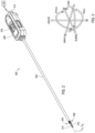
- FIG. 2 is an isometric side view of an example surgical tool 200 that may incorporate some or all of the principles of the present disclosure.
- the surgical tool 200 may be the same as or similar to the surgical tool(s) 108 of FIG. 1 and, therefore, may be used in conjunction with a robotic surgical system, such as the robotic surgical system 100 of FIG. 1 .
- the surgical tool 200 may be designed to be releasably coupled to a tool driver included in the robotic surgical system 100.
- aspects of the surgical tool 200 may be adapted for use in a manual or hand-operated manner, without departing from the scope of the disclosure.
- the surgical tool 200 includes an elongated shaft 202, an end effector 204, a wrist 206 (alternately referred to as a "wrist joint” or an “articulable wrist joint") that couples the end effector 204 to the distal end of the shaft 202, and a drive housing 208 coupled to the proximal end of the shaft 202.
- the drive housing 208 can include coupling features that releasably couple the surgical tool 200 to the robotic surgical system.
- proximal and distal are defined herein relative to a robotic surgical system having an interface configured to mechanically and electrically couple the surgical tool 200 (e.g., the housing 208) to a robotic manipulator.
- proximal refers to the position of an element closer to the robotic manipulator and the term “distal” refers to the position of an element closer to the end effector 204 and thus further away from the robotic manipulator.
- distal refers to the position of an element closer to the end effector 204 and thus further away from the robotic manipulator.
- proximal and distal are defined herein relative to a user, such as a surgeon or clinician.
- proximal refers to the position of an element closer to the user and the term “distal” refers to the position of an element closer to the end effector 204 and thus further away from the user.
- distal refers to the position of an element closer to the end effector 204 and thus further away from the user.
- use of directional terms such as above, below, upper, lower, upward, downward, left, right, and the like are used in relation to the illustrative embodiments as they are depicted in the figures, the upward or upper direction being toward the top of the corresponding figure and the downward or lower direction being toward the bottom of the corresponding figure.
- the end effector 204 is configured to move (pivot) relative to the shaft 202 at the wrist 206 to position the end effector 204 at desired orientations and locations relative to a surgical site.
- the housing 208 includes (contains) various drive inputs and mechanisms (e.g., gears, actuators, etc.) designed to control operation of various features associated with the end effector 204 (e.g., clamping, firing, cutting, rotation, articulation, etc.).
- the shaft 202, and hence the end effector 204 coupled thereto is configured to rotate about a longitudinal axis A 1 of the shaft 202.
- at least one of the drive inputs included in the housing 208 is configured to control rotational movement of the shaft 202 about the longitudinal axis A 1 .
- the shaft 202 is an elongate member extending distally from the housing 208 and has at least one lumen extending therethrough along its axial length.
- the shaft 202 may be fixed to the housing 208, but could alternatively be rotatably mounted to the housing 208 to allow the shaft 202 to rotate about the longitudinal axis A 1 .
- the shaft 202 may be releasably coupled to the housing 208, which may allow a single housing 208 to be adaptable to various shafts having different end effectors.
- the end effector 204 can exhibit a variety of sizes, shapes, and configurations.
- the end effector 204 comprises a combination tissue grasper and vessel sealer that include opposing first (upper) and second (lower) jaws 210, 212 configured to move (articulate) between open and closed positions.
- the opposing jaws 210, 212 may alternatively form part of other types of end effectors such as, but not limited to, a surgical scissors, a clip applier, a needle driver, a babcock including a pair of opposed grasping jaws, bipolar jaws (e.g., bipolar Maryland grasper, forceps, a fenestrated grasper, etc.), etc.
- One or both of the jaws 210, 212 may be configured to pivot to articulate the end effector 204 between the open and closed positions.
- FIG. 3 illustrates the potential degrees of freedom in which the wrist 206 may be able to articulate (pivot) and thereby move the end effector 204.
- the wrist 206 can have any of a variety of configurations.
- the wrist 206 comprises a joint configured to allow pivoting movement of the end effector 204 relative to the shaft 202.
- the degrees of freedom of the wrist 206 are represented by three translational variables (i.e., surge, heave, and sway), and by three rotational variables (i.e., Euler angles or roll, pitch, and yaw).
- the translational and rotational variables describe the position and orientation of the end effector 204 with respect to a given reference Cartesian frame. As depicted in FIG.
- the pivoting motion can include pitch movement about a first axis of the wrist 206 (e.g., X-axis), yaw movement about a second axis of the wrist 206 (e.g., Y-axis), and combinations thereof to allow for 360° rotational movement of the end effector 204 about the wrist 206.
- the pivoting motion can be limited to movement in a single plane, e.g., only pitch movement about the first axis of the wrist 206 or only yaw movement about the second axis of the wrist 206, such that the end effector 204 moves only in a single plane.
- the surgical tool 200 may also include a plurality of drive cables (obscured in FIG. 2 ) that form part of a cable driven motion system configured to facilitate actuation and articulation of the end effector 204 relative to the shaft 202.
- Moving (actuating) one or more of the drive cables moves the end effector 204 between an unarticulated position and an articulated position.
- the end effector 204 is depicted in FIG. 2 in the unarticulated position where a longitudinal axis A 2 of the end effector 204 is substantially aligned with the longitudinal axis A 1 of the shaft 202, such that the end effector 204 is at a substantially zero angle relative to the shaft 202.
- the end effector 204 may not be at a precise zero angle relative to the shaft 202 in the unarticulated position, but nevertheless be considered “substantially aligned" thereto.
- the longitudinal axes A 1 , A 2 would be angularly offset from each other such that the end effector 204 is at a non-zero angle relative to the shaft 202.
- the surgical tool 200 may be supplied with electrical power (current) via a power cable 214 coupled to the housing 208.
- the power cable 214 may be omitted and electrical power may be supplied to the surgical tool 200 via an internal power source, such as one or more batteries, capacitors, or fuel cells.
- the surgical tool 200 may alternatively be characterized and otherwise referred to as an "electrosurgical instrument" capable of providing electrical energy to the end effector 204.
- the power cable 214 may place the surgical tool 200 in electrical communication with a generator 216 that supplies energy, such as electrical energy (e.g., radio frequency energy), ultrasonic energy, microwave energy, heat energy, or any combination thereof, to the surgical tool 200 and, more particularly, to the end effector 204.
- energy such as electrical energy (e.g., radio frequency energy), ultrasonic energy, microwave energy, heat energy, or any combination thereof, to the surgical tool 200 and, more particularly, to the end effector 204.
- the generator 216 may comprise a radio frequency (RF) source, an ultrasonic source, a direct current source, and/or any other suitable type of electrical energy source that may be activated independently or simultaneously.
- RF radio frequency
- the power cable 214 will include a supply conductor and a return conductor.
- Current can be supplied from the generator 216 to an active (or source) electrode located at the end effector 204 via the supply conductor, and current can flow back to the generator 216 via a return electrode located at the end effector 204 via the return conductor.
- the jaws serve as the electrodes where the proximal end of the jaws are isolated from one another and the inner surface of the jaws (i.e., the area of the jaws that grasp tissue) apply the current in a controlled path through the tissue.
- the generator 216 transmits current through a supply conductor to an active electrode located at the end effector 204, and current is returned (dissipated) through a return electrode (e.g., a grounding pad) separately coupled to a patient's body.
- a return electrode e.g., a grounding pad
- the surgical tool 200 may further include a manual release switch 218 that may be manually actuated by a user (e.g., a surgeon) to open the jaws 210, 212.
- the release switch 218 is movably positioned on the drive housing 208, and a user is able to manually move (slide) the release switch 218 from a disengaged position, as shown, to an engaged position. In the disengaged position, the surgical tool 200 is able to operate as normal.
- the release switch 218 moves to the engaged position, however, various internal component parts of the drive housing 208 are simultaneously moved, thereby resulting in the jaws 210, 212 opening, which might prove beneficial for a variety of reasons.
- the release switch 218 may be moved in the event of an electrical disruption that renders the surgical tool 200 inoperable. In such applications, the user would be able to manually open the jaws 210, 212 and thereby release any grasped tissue and remove the surgical tool 200. In other applications, the release switch 218 may be actuated (enabled) to open the jaws 210, 212 in preparation for cleaning and/or sterilization of the surgical tool 200. In some applications, the surgical tool 200 is first decoupled from the robotic manipulator and the associated motors, following which the user can actuate the manual release switch 218 to move the associated inputs and drive the cables once the motors are disengaged.
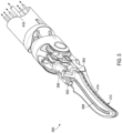
- FIG. 4 is an enlarged isometric view of the distal end of the surgical tool 200. More specifically, FIG. 4 depicts an enlarged view of the end effector 204 and the wrist 206, with the jaws 210, 212 of the end effector 204 in the closed position.
- the wrist 206 operatively couples the end effector 204 to the shaft 202.
- a shaft adapter may be directly coupled to the wrist 206 and otherwise interpose the shaft 202 and the wrist 206.
- the wrist 206 may be operatively coupled to the shaft 202 either through a direct coupling engagement where the wrist 206 is directly coupled to the distal end of the shaft 202, or an indirect coupling engagement where a shaft adapter interposes the wrist 206 and the distal end of the shaft 202.
- operatively couple refers to a direct or indirect coupling engagement between two components.
- the wrist 206 To operatively couple the end effector 204 to the shaft 202, the wrist 206 includes a first or “distal" clevis 402a and a second or “proximal” clevis 402b.
- the clevises 402a,b are alternatively referred to as "articulation joints" of the wrist 206 and extend from the shaft 202, or alternatively a shaft adapter.
- the clevises 402a,b are operatively coupled to facilitate articulation of the wrist 206 relative to the shaft 202.
- the wrist 206 also includes a linkage 404 arranged distal to the distal clevis 402a and operatively mounted to the jaws 210, 212.
- the proximal end of the distal clevis 402a may be rotatably mounted or pivotably coupled to the proximal clevis 402b at a first pivot axis P 1 of the wrist 206.
- an axle may extend through the first pivot axis P 1 and the distal and proximal clevises 402a,b may be rotatably coupled via the axle.
- the distal and proximal clevises 402a,b may be engaged in rolling contact, such as via an intermeshed gear relationship that allows the clevises 402a,b to rotate relative to each other similar to a rolling joint.
- First and second pulleys 406a and 406b may be rotatably mounted to the distal end of the distal clevis 402a at a second pivot axis P 2 of the wrist 206.
- the linkage 404 may be arranged distal to the second pivot axis P 2 and operatively mounted to the jaws 210, 212.
- the first pivot axis P 1 is substantially perpendicular (orthogonal) to the longitudinal axis A 1 of the shaft 202
- the second pivot axis P 2 is substantially perpendicular (orthogonal) to both the longitudinal axis A 1 and the first pivot axis P 1 . Movement of the end effector 204 about the first pivot axis P 1 provides "yaw" articulation of the wrist 206, and movement about the second pivot axis P 2 provides "pitch" articulation of the wrist 206.
- a plurality of drive cables extend longitudinally within a lumen 410 defined by the shaft 202 (or a shaft adaptor) and extend at least partially through the wrist 206.
- the drive cables 408a-d may form part of the cable driven motion system housed within the drive housing 208 ( FIG. 2 ), and may comprise cables, bands, lines, cords, wires, woven wires, ropes, strings, twisted strings, elongate members, belts, shafts, flexible shafts, drive rods, or any combination thereof.
- the drive cables 408a-d can be made from a variety of materials including, but not limited to, a metal (e.g., tungsten, stainless steel, nitinol, etc.), a polymer (e.g., ultra-high molecular weight polyethylene), a synthetic fiber (e.g., KEVLAR ® , VECTRAN ® , etc.), an elastomer, or any combination thereof. While four drive cables 408a-d are depicted in FIG. 4 , more or less than four may be employed, without departing from the scope of the disclosure.
- a metal e.g., tungsten, stainless steel, nitinol, etc.
- a polymer e.g., ultra-high molecular weight polyethylene
- a synthetic fiber e.g., KEVLAR ® , VECTRAN ® , etc.
- an elastomer elastomer
- the drive cables 408a-d extend proximally from the end effector 204 and the wrist 206 toward the drive housing 208 ( FIG. 2 ) where they are operatively coupled to various actuation mechanisms or devices that facilitate longitudinal movement (translation) of the drive cables 408a-d within the lumen 410.
- Selective actuation of the drive cables 408a-d applies tension (i.e., pull force) to the given drive cable 408a-d in the proximal direction, which urges the given drive cable 408a-d to translate longitudinally within the lumen 410.
- the drive cables 408a-d each extend longitudinally through the proximal clevis 402b.
- the distal end of each drive cable 408a-d terminates at the first or second pulleys 406a,b, thus operatively coupling each drive cable 408a-d to the end effector 204.
- the distal ends of the first and second drive cables 408a,b may be coupled to each other and terminate at the first pulley 406a
- the distal ends of the third and fourth drive cables 408c,d may be coupled to each other and terminate at the second pulley 406b.
- the distal ends of the first and second drive cables 408a,b and the distal ends of the third and fourth drive cables 408c,d may each be coupled together at corresponding ball crimps (not shown) mounted to the first and second pulleys 406a,b, respectively.
- the drive cables 408a-d may operate "antagonistically". More specifically, when the first drive cable 408a is actuated (moved), the second drive cable 408b naturally follows as coupled to the first drive cable 408a, and when the third drive cable 408c is actuated, the fourth drive cable 408d naturally follows as coupled to the third drive cable 408c, and vice versa. Antagonistic operation of the drive cables 408a-d can open or close the jaws 210, 212 and can further cause the end effector 204 to articulate at the wrist 206.
- selective actuation of the drive cables 408a-d in known configurations or coordination can cause the end effector 204 to articulate about one or both of the pivot axes P 1 , P 2 , thus facilitating articulation of the end effector 204 in both pitch and yaw directions.
- selective actuation of the drive cables 408a-d in other known configurations or coordination will cause the jaws 210, 212 to open or close.
- Antagonistic operation of the drive cables 408a-d advantageously reduces the number of cables required to provide full wrist 206 motion, and also helps eliminate slack in the drive cables 408a-d, which results in more precise motion of the end effector 204.
- the end effector 204 is able to articulate (move) in pitch about the second or "pitch" pivot axis P 2 , which is located near the distal end of the wrist 206.
- the jaws 210, 212 open and close in the direction of pitch.
- the wrist 206 may alternatively be configured such that the second pivot axis P 2 facilitates yaw articulation of the jaws 210, 212, without departing from the scope of the disclosure.
- an electrical conductor 412 may also extend longitudinally within the lumen 410, through the wrist 206, and terminate at an electrode 414 to supply electrical energy to the end effector 204.
- the electrical conductor 412 may comprise a wire, but may alternatively comprise a rigid or semi-rigid shaft, rod, or strip (ribbon) made of a conductive material.
- the electrical conductor 412 may be entirely or partially covered with an insulative covering (overmold) made of a non-conductive material.
- the end effector 204 may be configured for monopolar or bipolar RF operation.
- the end effector 204 comprises a combination tissue grasper and vessel sealer that includes a knife (not visible), alternately referred to as a "cutting element” or “blade.”
- the knife is aligned with and configured to traverse a guide track or "knife slot” (not visible) defined longitudinally in one or both of the upper and lower jaws 210, 212.
- the knife may be operatively coupled to the distal end of a drive rod 416 (alternately referred to as "knife rod,” “actuation rod,” or “push rod”) that extends longitudinally within the lumen 410 and passes through the wrist 206. Longitudinal movement (translation) of the drive rod 416 correspondingly moves the knife within the knife slot(s).
- the drive rod 416 may form part of the actuation systems housed within the drive housing 208 ( FIG. 2 ). Selective actuation of a corresponding drive input will cause the drive rod 416 to move distally or proximally within the lumen 410, and correspondingly move the knife in the same longitudinal direction.
- the drive rod 416 may comprise a rigid or semi rigid elongate member, such as a rod or shaft (e.g., a hypotube, a hollow rod, a solid rod, etc.), a wire, a ribbon, a push cable, or any combination thereof.
- the drive rod 416 can be made from a variety of materials including, but not limited to, metal (e.g., tungsten, nitinol, stainless steel, etc.), a polymer, or a composite material.
- the drive rod 416 may have a circular cross-section, but may alternatively exhibit a polygonal cross-section without departing from the scope of the disclosure.
- FIG. 5 is another enlarged isometric view of the end effector 204, according to one or more embodiments of the present disclosure.
- the upper jaw 210 ( FIGS. 2 and 4 ) is omitted from FIG. 5 to enable viewing of various internal features of the end effector 204.
- a knife 502 (mostly occluded) is shown received within a portion of the electrode 414 of the lower jaw 212 and, more particularly, within a portion of an insulator 504 coupled to the electrode 414.
- the knife 502 In its retracted position, as shown in FIG. 5 , the knife 502 may also be partially received within a knife housing 506 mounted to the end effector 204 between the upper and lower jaws 210, 212.
- the lower jaw 212 provides or otherwise defines a knife slot 508 through which the knife 502 may traverse upon distal actuation of the drive rod 416. While the knife slot 508 is shown provided in the lower jaw 212, in some embodiments, the knife slot 508 may be cooperatively defined by both the upper and lower jaws 210, 212.
- the knife housing 506 defines a central passageway through which the drive rod 416 is able to extend to move the knife 502 along the knife slot 508.
- the drive rod 416 Upon firing the end effector 204, the drive rod 416 is moved (urged) distally, which correspondingly moves the knife 502 out of the knife housing 506 and into the knife slot 508. After firing is complete, the drive rod 416 is retracted proximally, which pulls the knife 502 proximally and back into the knife housing 506 until it is desired to again fire the end effector 204.
- FIGS. 6A and 6B are enlarged isometric views of the knife 502 and the knife housing 506, according to one or more embodiments.
- the knife 502 is shown in a first or “stowed” position, where the knife 502 is at least partially received within a cavity 602 defined by the knife housing 506 and sized to receive and "stow” the knife 502 when not in use.
- the knife 502 is shown in a second or “extended” position, where the knife 502 is extended distally out of the cavity 602.
- the knife 502 may be operatively coupled to the distal end of the drive rod 416 (shown in dashed lines in FIG. 6A ).
- a central passageway 604 is defined through the knife housing 506 and provides a conduit through which the drive rod 416 is able to extend to move the knife 502 into and along the knife slot 508 ( FIG. 5 ).
- the cavity 602 may form part of or communicate with the central passageway 604.
- the drive rod 416 may comprise a solid shaft, but may alternatively comprise a tube or tubular structure.
- the drive rod 416 may be made of a variety of flexible materials including, but not limited to, a metal or metal alloy (e.g., a nickel-titanium alloy or "nitinol”), a plastic or thermoplastic material, a composite material, or any combination thereof.
- the drive rod 416 may also comprise a braided cable construction of a metal (e.g., stainless steel, tungsten, etc.), or any of the aforementioned materials, and such braided cable may be radially constrained to support axial loads.
- a flexible sheath 606 may cover at least a portion of the drive rod 416.
- the sheath 606 may support and help prevent buckling of the drive rod 416 when assuming compressive loads during articulation of the wrist 206 ( FIGS. 2 and 4 ) and opening and closure of the jaws 210, 212 ( FIGS. 2 and 4 ).
- the flexible sheath 606 may be made of a variety of flexible materials including, but not limited to, a metal or metal alloy (e.g., a nickel-titanium alloy or "nitinol”), a metallic coil, a plastic or thermoplastic material, a composite material, a braided tubular, or any combination thereof.
- a metal or metal alloy e.g., a nickel-titanium alloy or "nitinol”
- a metallic coil e.g., a nickel-titanium alloy or "nitinol”
- plastic or thermoplastic material e.g., a plastic or thermoplastic material, a composite material, a braided tubular, or any combination thereof.
- the knife 502 may be attached to the distal end of the drive rod 416 at a connecting or "retention" feature 608.
- the retention feature 608 may comprise any attachment or coupling means that removably or permanently fixes the knife 502 to the drive rod 416.
- the retention feature 608 may comprise, but is not limited to, a crimped engagement, a welded interface, an adhesive attachment, an interference or shrink fit, an overmold (e.g., a shaped block of material or a support block), one or more mechanical fasteners, or any combination thereof.
- the retention feature 608 may comprise a metal tube crimped or press fit to the distal end of the drive rod 416.
- the drive rod 416 Upon firing the end effector 204 ( FIGS. 2 and 4 ), the drive rod 416 is moved (urged) distally through the central passageway 604, which correspondingly moves the knife 502 to the extended position and otherwise out of the cavity 602 and into the knife slot 508 ( FIG. 5 ). As the drive rod 416 translates distally, the sheath 606 supports the drive rod 416 against axial buckling resulting from compressive loading on the drive rod 416. After firing is complete, the drive rod 416 is retracted proximally, which correspondingly pulls the knife 502 proximally and back to the stowed position and otherwise into the cavity 602 until it is desired to again fire the end effector 204.
- Some end effectors can articulate in two planes simultaneously, which requires the knife 502 and the drive rod 416 to traverse the articulation joints while still applying adequate cut force.
- moving knife 502 in the retract direction may result in contacting a hard stop, retract overdrive prevention, or positional locator to be fed into manufacturing settings or controls schemes. In some cases, this can cause the knife 502 to prematurely fail and otherwise separate from the retention feature 608 and/or the drive rod 416.
- the knife 502 may be operatively coupled to the retention feature 608 and the drive rod 416 with a mechanical locking feature, which helps assume any axial loading resulting, including retract, retraction overdrive prevention, and positional locating loadings.
- FIGS. 7A and 7B are side and exploded isometric views, respectively, of the knife 502 as coupled to the distal end of the drive rod 416, according to one or more embodiments.
- the retention feature 608 may be secured to the distal end of the drive rod 416.
- the retention feature 608 may be made of a material capable of allowing the knife 502 to be welded thereto.
- the retention feature 608 may be made of a metal, such as stainless steel.
- the retention feature 608 may also be made of Nitinol.
- the retention feature 608 may comprise a short tubular length or tube. More specifically, the retention feature 608 may comprise a tubular body 702 having a first or “distal” and 704a and a second or “proximal” end 704b opposite the distal end 704a.
- the tubular body 702 may provide an inner conduit or passageway sized to receive the distal end of the drive rod 416a.
- the body 702 of the retention feature 608 may be secured to the drive rod 416 in a variety of ways including, but not limited to, crimping, press fitting, shrink fitting, an adhesive, or any combination thereof.
- a central notch 706 may be cut into and otherwise defined in the body 702 at a location between the distal and proximal ends 704a,b. As illustrated, the central notch 706 may extend through the side wall of the body 702 and partially into the underlying material of the drive rod 416. In some embodiments, the central notch 706 may be defined and otherwise formed via grinding or through a grinding process, but could alternatively be formed through other processes, such as laser cutting, wire electrical discharge machining (EDM), milling, chemical etching, water jetting, stamping, or the like.
- EDM wire electrical discharge machining
- the depth of the central notch 706 into the material of the drive rod 416 may stop short of the centerline of the drive rod 416. In other embodiments, however the depth of the central notch 706 may extend past the centerline of the drive rod 416, without departing from the scope of the disclosure.
- the knife 502 may provide and otherwise define a locking feature 708 sized or configured to be received within the central notch 706 when the knife 502 is properly mounted to the retention feature 608.
- the locking feature 708 may be laser cut into the body of the knife 502, but could alternatively be defined via other manufacturing or forming processes, without departing from the scope of the disclosure.
- the locking feature 708 comprises a generally rectangular projection or tab that extends from the bottom of the main body of the knife 502. In other embodiments, however, the locking feature 708 may exhibit other geometric shapes including, but not limited to, angled, arcuate, rounded, or any combination thereof. In some embodiments, when mounting the knife 502 to the retention feature 608, the locking feature 708 may extend into the central notch 706 but not contact the bottom of the central notch 706, such as the material of the drive rod 416. In such embodiments, a gap 712 may be defined between the bottom of the central notch 706 and the outer extent of the locking feature 708. In other embodiments, however, the locking feature 708 may be designed and otherwise configured to contact or rest on the bottom of the central notch 706.
- the knife 502 may be welded to the outer surface of the retention feature 608 at one or more locations. More specifically, the knife 502 may be welded to the retention feature 608 at a first weld 710a located distal to the central notch 706, and a second weld 710a located proximal to the central notch 706. In other embodiments, however, one of the welds 710a,b may be omitted, without departing from the scope of the disclosure. In some applications, the gap 712 may prove advantageous in ensuring that there is intimate (direct) contact between the retention feature 608 and the blade 502, which can promote more robust welds 710a,b.
- the length L 1 of the distal weld 710a may be smaller than the length L 2 of the proximal weld 710b. This may prove advantageous since the stress concentration region of the drive rod 416 (e.g., the proximal notch corner) is further away from where the drive rod 416 exits the retention feature 608 such that it takes less of the bending loading (from articulation and retraction) further away from the proximal edge. In addition, the retraction loads commonly result in the primary loading of the proximal-most region of the weld, so having a more robust (longer) proximal weld may help mitigate separation of the knife 502 from the retention feature 608.
- the length L 1 of the distal weld 710a may be larger than the length L 2 of the proximal weld 710b, or the lengths L 1 , L 2 may be the same, without departing from the scope of the disclosure.
- the length from the proximal end of the central notch 716 to the proximal end of the retention feature 608 may be longer than the length from the distal end of the central notch 706 to the distal end of the retention feature 608. This may help accommodate the longer length L 2 versus the shorter length L 1 , but may also prove advantageous in helping with fatigue life as there is larger length between the bending flexible region of the knife rod 416 to the area of the central notch 706.
- the locking feature 708 may be received within the central notch 706 such that a distal end 714a of the locking feature 708 contacts and otherwise engages an opposing distal end 714b of the central notch 706, and thereby axially constrains the knife 502 to the retention features 608 and the drive rod 416. More particularly, engaging the opposing distal ends 714a,b may prove advantageous in transmitting axial loads from the knife 502 to the drive rod 416 and thus helping to prevent premature failure of the knife 502; e.g., separation of the knife 502 from the retention feature 608.
- the knife 502 when the knife 502 is positionally located or retracted, as briefly mentioned above, the knife 502 is moved proximally and stowed within the knife housing 506 ( FIGS. 6A-6B ).
- an axial load is applied on the drive rod 416 to return the knife 502 and/or force the knife 502 into axial engagement with the knife housing 506.
- Having the opposing distal ends 714a,b in contact allows the knife 502 to transmit a resulting axial load caused by contact with the knife housing 506 directly to the drive rod 416.
- the welds 710a,b may help vertically constrain the knife 502 to the drive rod 416 via the retention feature 608, receiving the locking feature 708 within the central notch 706 may provide additional axial constraint and load transfer that helps prevent the knife 502 from prematurely separating from the drive rod 416. Consequently, the locking feature 708 enables sustaining of higher and increased retraction, retract over drive prevention, and positional locating loads.
- an end notch 716 may be cut into and otherwise defined in the distal end of the drive rod 416. As illustrated, the end notch 716 may extend through the distal end 704a of the retention feature 608 and partially into the material of the drive rod 416. The end notch 716 may be defined and otherwise formed through any of the processes mentioned above for forming the central notch 706. In at least one embodiment, as illustrated, the end notch 716 may extend orthogonal to the central notch 706.
- the knife 502 may provide and otherwise define an end tab 718 sized to be received within the end notch 716. Receiving the end tab 718 in the end notch 716 may help laterally stabilize the knife 502 when mounted to the retention feature 608. Moreover, receiving the end tab 718 in the end notch 716 may further prove advantageous in transferring axial loads in the fire direction directly from the drive rod 416 to the end tab 718. In at least one embodiment, the knife 502 may further be welded to the distal end of the drive rod 416 at the interface between the end tab and the end notch 716.
- FIGS. 8A and 8B are side and exploded isometric views, respectively, of another example of the knife 502 as coupled to the distal end of the drive rod 416, according to one or more additional embodiments.
- the knife 502 shown in FIGS. 8A-8B may be similar in some respects to the knife 502 shown in FIGS. 7A-7B , and therefore may be best understood with reference thereto, where like numerals will correspond to like components not described again in detail.
- the knife 502 of FIGS. 8A-8B includes the retention feature 608 secured to the distal end of the drive rod 416, and the central notch 706 is defined in the retention feature 608 and may extend partially into the underlying material of the drive rod 416.
- the knife 502 provides the locking feature 708 sized to be received within the central notch 706, and the knife 502 can be secured to the outer surface of the retention feature 608 using one or both of the welds 710a,b (see FIG. 8A ), as generally described above.
- the end tab 718 provided by the knife 502 may be received within the end notch 716 defined in the distal ends of the drive rod 416 and the retention feature 608.
- the knife 502 of FIGS. 8A-8B may include a dual-edge blade 802 provided at a distal or "leading" end 804a of the knife 502.
- the blade 802 is the sharp portion of the knife 502 opposite a proximal or “trailing" end 804b of the knife 502 and configured to sever or otherwise cut through tissue as the end effector 204 ( FIGS. 2 and 4 ) fires and advances the knife 502 during operation.
- the blade 802 may include a first or "leading" cutting edge 806a and a second or “angled” cutting edge 806b that extends from the leading cutting edge 806a at a transition point 808.
- the leading cutting edge 806a may extend substantially orthogonal or perpendicular to a centerline 810 of the drive rod 416. Moreover, as explained in more detail below, the leading cutting edge 806b may also extend perpendicular to the sealing plane of the end effector 204 ( FIGS. 2 and 4 ). As best seen in FIG. 8A , the angled cutting edge 806b extends from the leading cutting edge 806a at the transition point 808 and at an angle 812 offset from perpendicular to the centerline 810 (or the sealing plane of the end effector 204). The angle 812 may range between about 1° and about 60°, and any subset therebetween.
- transition point 808 may comprise a sharp corner or transition between the leading and angled cutting edges 806a,b. In other embodiments, however, transition point may comprise an arcuate or curved transition between the leading an angled cutting edges 806a,b, without departing from the scope of the disclosure.
- FIG. 9 illustrated is an enlarged side view of the end effector 204 with the knife 502 during firing, according to one or more embodiments. More specifically, the end effector 204 is depicted in FIG. 9 in phantom, thus allowing a view of the knife 502 in the process of firing and otherwise being advanced distally (or proximally) within the knife slot 508 ( FIG. 5 ).
- the end effector 204 includes the upper jaw 210 and the lower jaw 212, and a gap 902 is defined between the upper and lower jaws 210, 212 when the jaws 210, 212 are closed.
- the upper jaw 210 provides an upper surface 904a and the lower jaw 212 provides an opposing lower surface 904b.
- the lower surface 904b may be the same structure as the electrode 414 ( FIGS. 4 and 5 ) attached to or forming part of the lower jaw 212.
- the upper surface 904a may also comprise an electrode, but may otherwise comprise a planar sealing surface made of a nonconductive material (e.g., an insulator).
- the upper and lower surfaces 904a,b oppose each other and cooperatively form a sealing plane 906 that extends through the gap 902.
- the sealing plane 906 is alternately referred to as a "tissue capturing section" since the sealing plane 906 is the location where tissue can be grasped between the upper and lower jaws 210, 212 in preparation for cutting with the knife 502.
- the leading cutting edge 806a extends substantially perpendicular to the sealing plane 906.
- the entirety of the leading cutting edge 806a may be disposed below the sealing plane 906 and within the knife slot 508 ( FIG. 5 ) defined in the lower jaw 212.
- the transition point 808 may also be disposed below the sealing plane 906.
- the leading cutting edge 806a may extend to or above the sealing plane 906, thus also providing the transition point 808 at or above the sealing plane 906, without departing from the scope of the disclosure.
- the leading cutting edge 806a may be arranged and otherwise configured to cut tissue that may be located below the sealing plane 806, such as tissue that may migrate or "milk" into the knife slot 508 upon closing the jaws 210, 212.
- leading cutting edge 806a and the angled cutting edge 806b are positioned fully below the sealing plane 906, and only the leading cutting edge 806a is present in the sealing plane 906.
- the leading cutting edge 806a being perpendicular to the sealing plane at 906 may also prove advantageous in providing a longer stroke length for the knife 502. More specifically, other knife designs, such as the knife 502 depicted in FIGS. 7A-7B , exhibit a fully angled cutting edge (extending top to bottom) that extends distally further than the distal location of the leading cutting edge 806a. As will be appreciated, this can limit how far the knife 502 can be advanced within the knife slot 508 ( FIG. 5 ) since the angled bottom or "leading tip" of the fully angled cutting edge will engage the distal end of the knife slot 508. This can also result in breakage of the leading tip of the fully angled cutting edge by repeatedly engaging the distal end of the knife slot 508.
- leading tip can cause friction as the knife 502 traverses the curvature of the knife slot 508.
- leading cutting edge 806a extends perpendicular to the sealing plane 906 and thereby demonstrates a decrease in the active length of the knife 502, thus increasing potential overall cut length of the knife 502 along the knife slot 508.
- the trailing end 804b of the knife 502 of FIGS. 8A-8B may include or otherwise define a reduced trailing profile 814.
- the reduced trailing profile 814 may prove advantageous as the knife 502 traverses the knife slot 508 ( FIG. 5 ).
- the knife slot 508 is curved, and sometimes referred to as a Maryland-style knife track.
- Other knife designs, such as the knife 502 of FIGS. 7A-7B provide or exhibit a full trailing profile that may catch or contact portions of the knife slot 508 provided in the upper jaw 210 ( FIGS. 2 and 4 ) as the knife traverses the knife slot 508 when firing or retracting. Contacting the knife slot 508 during firing or retracting generates frictional loading and inefficiencies.
- the reduced trailing profile 814 of the knife 502 of FIGS. 8A-8B provides less surface area at the trailing end 804b and is therefore less prone to catch or contact portions of the knife slot 508 provided in the upper jaw 210 ( FIGS. 2 and 4 ). More particularly, the reduced trailing profile 814 allows the knife 502 to navigate the curved knife slot 508 more easily and without significant frictional loading, including significant reduction in frictional drag when passing through tissue. Moreover, the reduced trailing profile 814 may lead to a significant reduction in sensitivity to cutting tissue in non-perpendicular orientations (e.g., cutting in the curvature of the knife slot 508, blade tilt, misalignment, etc.).
- the reduced trailing profile 814 also enables larger manufacturing tolerances due to less sensitivity. Lastly, the reduced trailing profile 814 may potentially reduce the amount of tissue particulate pulled back into the jaws 210, 212 ( FIGS. 2 and 4 ), since there will be less tissue build-up.
- the reduced trailing profile 814 may include a first arcuate surface 816a extending from a top 818 of the knife 502, and the first arcuate surface 816a transitions to a second arcuate surface 816b, which then transitions to a third arcuate surface 816c. Accordingly, in at least one embodiment, the reduced trailing profile 814 may include three contiguous arcuate surfaces 816a-c. As illustrated, the first and third arcuate surfaces 816a,c may each be convex surfaces, and the second arcuate surface 816 be may be a concave surface.
- a first straight surface 820a may interpose the first and second arcuate surfaces 816a,b, and a second straight surface 820b may interpose the second and third arcuate surfaces 816b,c.
- the first and second straight surfaces 820a,b may extend perpendicular to each other.
- a third straight surface 820c may extend from the third arcuate surface 816c, and the third straight surface 820c may extend generally parallel to the first straight surface 820a and perpendicular to the second straight surface 820b.
- the third straight surface 820c may extend substantially perpendicular to the centerline 810 of the drive rod 416. In other embodiments, however, the third straight surface 820c may extend at other angles relative to the centerline 180, without departing from the scope of the disclosure. In at least one embodiment the third straight surface 820c may be used to help positionally locate the knife 502 within the knife housing 506 ( FIGS. 5 and 6A-6B ) or to act as a hard stop or over-drive prevention feature. More specifically, as the knife 502 is retracted to the stowed position, as described above, the third straight surface 820c may be configured to engage a portion of the knife housing 506 within the cavity 602 ( FIGS. 6A-6B ). In other embodiments, however, as the knife 502 is retracted to the stowed position, the first straight surface 820a may alternatively be used to the knife housing for retraction, hard stops, over-drive prevention, and positional locating loads.
- a bottom 822 (shown in dashed lines) of the knife 502 at the leading end 804a may be curved and otherwise exhibit a radius. Having a curved bottom 822 may prove advantageous in helping to prevent the knife 502 from catching in the knife slot 508 ( FIG. 5 ) when the knife 502 is moved in the distal direction (i.e., the "fire" direction). The curved bottom 822 may also result in less surface contact on the bottom of the knife 502 that might engage the bottom of the knife slot 508.
- the end tab 718 may define a curved proximal end 824, which may prove advantageous in helping to prevent the knife 502 from catching in the knife slot 508 ( FIG. 5 ) when the knife 502 is moved in the distal direction (i.e., the "fire" direction).
- the curved proximal end 824 may also help reduce dragging of tissue and/or debris that may be present within the knife slot 508.
Landscapes
- Health & Medical Sciences (AREA)
- Surgery (AREA)
- Life Sciences & Earth Sciences (AREA)
- Engineering & Computer Science (AREA)
- Medical Informatics (AREA)
- General Health & Medical Sciences (AREA)
- Biomedical Technology (AREA)
- Heart & Thoracic Surgery (AREA)
- Nuclear Medicine, Radiotherapy & Molecular Imaging (AREA)
- Molecular Biology (AREA)
- Animal Behavior & Ethology (AREA)
- Veterinary Medicine (AREA)
- Public Health (AREA)
- Physics & Mathematics (AREA)
- Otolaryngology (AREA)
- Plasma & Fusion (AREA)
- Robotics (AREA)
- Electromagnetism (AREA)
- Surgical Instruments (AREA)
Description
- Minimally invasive surgical (MIS) instruments are often preferred over traditional open surgical devices due to reduced post-operative recovery time and minimal scarring. Laparoscopic surgery is one type of MIS procedure in which one or more small incisions are formed in the abdomen of a patient and a trocar is inserted through the incision to form a pathway that provides access to the abdominal cavity. Through the trocar, a variety of instruments and surgical tools can be introduced into the abdominal cavity. The instruments and tools introduced into the abdominal cavity via the trocar can be used to engage and/or treat tissue in a number of ways to achieve a diagnostic or therapeutic effect.
- Various robotic systems have been developed to assist in MIS procedures. Robotic systems can allow for more instinctive hand movements by maintaining natural eye-hand axis. Robotic systems can also allow for more degrees of freedom in movement by including an articulable "wrist" joint that creates a more natural hand-like articulation. In such systems, an end effector positioned at the distal end of the instrument can be articulated (moved) using a cable driven motion system having one or more drive cables that extend through the wrist joint. A user (e.g., a surgeon) is able to remotely operate the end effector by grasping and manipulating in space one or more controllers that communicate with a tool driver coupled to the surgical instrument. User inputs are processed by a computer system incorporated into the robotic surgical system, and the tool driver responds by actuating the cable driven motion system. Moving the drive cables articulates the end effector to desired angular positions and configurations.
- Some end effectors also include a knife that is able to be advanced and retracted between opposing jaws to cut or sever tissue grasped between the opposing jaws. Improvements to the design and function of the knife are desirable to improve the efficiency of the end effector and any procedures undertaken with the end effector.
-
DE60226015T2 describes an electrosurgical instrument that includes a housing having a shaft attached thereto which connects a pair of first and second jaw members such that the jaw members are movable relative to one another to grasp tissue therebetween. The instrument also includes a four-bar handle assembly attached to the housing for actuating a drive rod assembly. The handle assembly includes a handle and a cam-like piston which cooperate to impart a uniform closure pressure against tissue grasped between the jaw members. The instrument also includes a rotating assembly for rotating the jaw members, a knife assembly for separating tissue and a pair of electrical leads connect the jaw members to a source of electrical energy. The electrical leads include slack loops disposed in the rotating assembly which permit rotation of the jaw members about the axis. -
US2020178994A1 describes an electrosurgical instrument that includes first and second jaw members each including an outer jaw housing, a tissue-treating plate, and a longitudinally-extending knife channel defined therethrough. The electrosurgical instrument also includes a knife actuator and a knife assembly operably coupled to the knife actuator. The knife actuator is configured to advance at least a portion of the knife assembly through the knife channel to cut tissue disposed between the jaw members. The knife assembly includes an elongated shaft having a proximal portion coupled to the knife actuator and a distal portion defining at least one aperture therethrough. The knife assembly also includes a knife blade having a sharpened distal end configured to cut tissue and at least one raised portion extending through the aperture defined by the elongated shaft. -
US5597107A describes a surgical stapler instrument for applying lateral lines of staples to tissue while cutting the tissue between those staple lines. The instrument includes a handle portion, an implement portion, a reciprocating section, a drive member and a movable actuator. The implement portion includes a staple cartridge and an anvil. The reciprocating section is adapted to move back and forth along an axis of the implement portion. The movable actuator is associated with the handle portion and is engaged with the drive member such that motion of the actuator causes the drive member to move back and forth between first and second drive positions separated by a first distance. -
US2020129198A1 describes an end effector that includes first and second jaws movable between open and closed positions, a guide track defined in the second jaw, and a cutting element extendable into the guide track and longitudinally movable within the guide track. A retention feature is positioned within the guide track and operatively couples the cutting element to a drive rod. The drive rod is actuatable to move the cutting element within the guide track, and the retention feature is larger than a width of an opening to the guide track such that the retention feature is retained within the guide track as the cutting element moves. -
DE60307820T2 describes an electrosurgical stapling apparatus that uses thermogenic energy as well as surgical fasteners or staples for strengthening tissue, providing hemostasis, tissue joining or welding. The thermogenic energy also strengthens tissue in proximity to a staple line and knife cut line and provides hemostasis along the staple and cut lines formed by the staples and a knife blade during surgical stapling. The use thermogenic energy provides short-term hemostasis and sealing, and reduces or prevents staple line and cut line bleeding, while the stapling features provide short and long-term tissue strength and hemostasis. The stapling apparatus further substantially reduces or prevents knife cut line bleeding by energizing a knife blade for cauterizing tissue while it is being cut. In one embodiment, energy is applied to the anvil to energize the staples as they make contact with the anvil. - The following figures are included to illustrate certain aspects of the present disclosure, and should not be viewed as exclusive embodiments. The subject matter disclosed is capable of considerable modifications, alterations, combinations, and equivalents in form and function, without departing from the scope of this disclosure. The scope of the invention is defined by claim 1.
-
FIG. 1 is a block diagram of an example robotic surgical system that may incorporate some or all of the principles of the present disclosure. -
FIG. 2 is an isometric side view of an example surgical tool that may incorporate some or all of the principles of the present disclosure. -
FIG. 3 illustrates potential degrees of freedom in which the wrist of the surgical tool ofFIG. 2 may be able to articulate (pivot) and translate. -
FIG. 4 is an enlarged isometric view of the distal end of the surgical tool ofFIG. 2 . -
FIG. 5 is another enlarged isometric view of the distal end of the surgical tool ofFIG. 2 , according to one or more embodiments of the present disclosure. -
FIGS. 6A and 6B are enlarged isometric views of the knife and the knife housing ofFIG. 5 , according to one or more embodiments. -
FIGS. 7A and 7B are side and exploded isometric views, respectively, of the knife and the distal end of the drive rod, according to one or more embodiments. -
FIGS. 8A and 8B are side and exploded isometric views, respectively, of another example of the knife as coupled to the distal end of the drive rod, according to one or more additional embodiments. -
FIG. 9 is an enlarged side view of the end effector with the knife during firing, according to one or more embodiments. - The present disclosure is related to surgical tools and, more particularly, to end effectors having improved knife attachment and functionality.
- Embodiments discussed herein describe an end effector for a surgical tool, where the end effector includes opposing first and second jaws, and a knife slot defined in one or both of the first and second jaws. A knife is extendable through the knife slot and may be operatively coupled to a knife rod at a retention feature secured to a distal end of the drive rod. More specifically, a central notch may be defined in the retention feature, and the knife may define a locking feature receivable within the central notch to axially constrain the knife to the retention feature and the knife rod. In at least one embodiment, the central notch extends into a material of the drive rod. Securing the knife to the drive rod at the locking feature and the central notch may prove advantageous in transmitting axial loads from the knife to the drive rod, and thus helping to prevent premature failure of the knife.
- In some embodiments, a blade is provided at a leading end of the knife and includes a leading cutting edge extending perpendicular to a sealing plane provided between the opposing first and second jaws when the opposing first and second jaws are closed, and an angled cutting edge extending from the leading cutting edge at a transition point. The angled cutting edge extends from the leading cutting edge at an angle offset from perpendicular to the sealing plane. Having the leading cutting edge perpendicular to the sealing plane may provide a longer stroke length for the knife.
- In some embodiments, the trailing end of the knife may provide a reduced trailing profile defined by a first arcuate surface extending from a top of the knife and transitioning to a second arcuate surface that transitions to a third arcuate surface. The reduced trailing profile may prove advantageous as the knife traverses the knife slot, which may be curved. While other knives without the reduced trailing profile may catch or contact portions of the curved knife slot, the reduced trailing profile eliminates this friction generating inefficiency.
-
FIG. 1 is a block diagram of an example robotic surgical system 100 that may incorporate some or all of the principles of the present disclosure. As illustrated, the system 100 can include at least one set ofuser input controllers 102a and at least onecontrol computer 104. Thecontrol computer 104 may be mechanically and/or electrically coupled to a robotic manipulator and, more particularly, to one or more robotic arms 106 (alternately referred to as "tool drivers"). In some embodiments, the robotic manipulator may be included in or otherwise mounted to an arm cart capable of making the system portable. Eachrobotic arm 106 may include and otherwise provide a location for mounting one or more surgical instruments ortools 108 for performing various surgical tasks on apatient 110. Operation of therobotic arms 106 and associatedtools 108 may be directed by aclinician 112a (e.g., a surgeon) from theuser input controller 102a. - In some embodiments, a second set of
user input controllers 102b (shown in dashed line) may be operated by asecond clinician 112b to direct operation of therobotic arms 106 andtools 108 via thecontrol computer 104 and in conjunction with thefirst clinician 112a. In such embodiments, for example, eachclinician 112a,b may control differentrobotic arms 106 or, in some cases, complete control of therobotic arms 106 may be passed between theclinicians 112a,b as needed. In some embodiments, additional robotic manipulators having additional robotic arms may be utilized during surgery on thepatient 110, and these additional robotic arms may be controlled by one or more of theuser input controllers 102a,b. - The
control computer 104 and theuser input controllers 102a,b may be in communication with one another via acommunications link 114, which may be any type of wired or wireless telecommunications means configured to carry a variety of communication signals (e.g., electrical, optical, infrared, etc.) according to any communications protocol. In some applications, for example, there is a tower with ancillary equipment and processing cores designed to drive therobotic arms 106. - The
user input controllers 102a,b generally include one or more physical controllers that can be grasped by theclinicians 112a,b and manipulated in space while the surgeon views the procedure via a stereo display. The physical controllers generally comprise manual input devices movable in multiple degrees of freedom, and which often include an actuatable handle for actuating the surgical tool(s) 108, for example, for opening and closing opposing jaws, applying an electrical potential (current) to an electrode, or the like. Thecontrol computer 104 can also include an optional feedback meter viewable by theclinicians 112a,b via a display to provide a visual indication of various surgical instrument metrics, such as the amount of force being applied to the surgical instrument (i.e., a cutting instrument or dynamic clamping member). -
FIG. 2 is an isometric side view of an examplesurgical tool 200 that may incorporate some or all of the principles of the present disclosure. Thesurgical tool 200 may be the same as or similar to the surgical tool(s) 108 ofFIG. 1 and, therefore, may be used in conjunction with a robotic surgical system, such as the robotic surgical system 100 ofFIG. 1 . Accordingly, thesurgical tool 200 may be designed to be releasably coupled to a tool driver included in the robotic surgical system 100. In other embodiments, however, aspects of thesurgical tool 200 may be adapted for use in a manual or hand-operated manner, without departing from the scope of the disclosure. - As illustrated, the
surgical tool 200 includes anelongated shaft 202, anend effector 204, a wrist 206 (alternately referred to as a "wrist joint" or an "articulable wrist joint") that couples theend effector 204 to the distal end of theshaft 202, and adrive housing 208 coupled to the proximal end of theshaft 202. In applications where the surgical tool is used in conjunction with a robotic surgical system (e.g., the robotic surgical system 100 ofFIG. 1 ), thedrive housing 208 can include coupling features that releasably couple thesurgical tool 200 to the robotic surgical system. - The terms "proximal" and "distal" are defined herein relative to a robotic surgical system having an interface configured to mechanically and electrically couple the surgical tool 200 (e.g., the housing 208) to a robotic manipulator. The term "proximal" refers to the position of an element closer to the robotic manipulator and the term "distal" refers to the position of an element closer to the
end effector 204 and thus further away from the robotic manipulator. Alternatively, in manual or hand-operated applications, the terms "proximal" and "distal" are defined herein relative to a user, such as a surgeon or clinician. The term "proximal" refers to the position of an element closer to the user and the term "distal" refers to the position of an element closer to theend effector 204 and thus further away from the user. Moreover, the use of directional terms such as above, below, upper, lower, upward, downward, left, right, and the like are used in relation to the illustrative embodiments as they are depicted in the figures, the upward or upper direction being toward the top of the corresponding figure and the downward or lower direction being toward the bottom of the corresponding figure. - During use of the
surgical tool 200, theend effector 204 is configured to move (pivot) relative to theshaft 202 at thewrist 206 to position theend effector 204 at desired orientations and locations relative to a surgical site. To accomplish this, thehousing 208 includes (contains) various drive inputs and mechanisms (e.g., gears, actuators, etc.) designed to control operation of various features associated with the end effector 204 (e.g., clamping, firing, cutting, rotation, articulation, etc.). In at least some embodiments, theshaft 202, and hence theend effector 204 coupled thereto, is configured to rotate about a longitudinal axis A1 of theshaft 202. In such embodiments, at least one of the drive inputs included in thehousing 208 is configured to control rotational movement of theshaft 202 about the longitudinal axis A1. - The
shaft 202 is an elongate member extending distally from thehousing 208 and has at least one lumen extending therethrough along its axial length. In some embodiments, theshaft 202 may be fixed to thehousing 208, but could alternatively be rotatably mounted to thehousing 208 to allow theshaft 202 to rotate about the longitudinal axis A1. In yet other embodiments, theshaft 202 may be releasably coupled to thehousing 208, which may allow asingle housing 208 to be adaptable to various shafts having different end effectors. - The
end effector 204 can exhibit a variety of sizes, shapes, and configurations. In the illustrated embodiment, theend effector 204 comprises a combination tissue grasper and vessel sealer that include opposing first (upper) and second (lower)jaws jaws jaws end effector 204 between the open and closed positions. -
FIG. 3 illustrates the potential degrees of freedom in which thewrist 206 may be able to articulate (pivot) and thereby move theend effector 204. Thewrist 206 can have any of a variety of configurations. In general, thewrist 206 comprises a joint configured to allow pivoting movement of theend effector 204 relative to theshaft 202. The degrees of freedom of thewrist 206 are represented by three translational variables (i.e., surge, heave, and sway), and by three rotational variables (i.e., Euler angles or roll, pitch, and yaw). The translational and rotational variables describe the position and orientation of theend effector 204 with respect to a given reference Cartesian frame. As depicted inFIG. 3 , "surge" refers to forward and backward translational movement, "heave" refers to translational movement up and down, and "sway" refers to translational movement left and right. With regard to the rotational terms, "roll" refers to tilting side to side, "pitch" refers to tilting forward and backward, and "yaw" refers to turning left and right. - The pivoting motion can include pitch movement about a first axis of the wrist 206 (e.g., X-axis), yaw movement about a second axis of the wrist 206 (e.g., Y-axis), and combinations thereof to allow for 360° rotational movement of the
end effector 204 about thewrist 206. In other applications, the pivoting motion can be limited to movement in a single plane, e.g., only pitch movement about the first axis of thewrist 206 or only yaw movement about the second axis of thewrist 206, such that theend effector 204 moves only in a single plane. - Referring again to
FIG. 2 , thesurgical tool 200 may also include a plurality of drive cables (obscured inFIG. 2 ) that form part of a cable driven motion system configured to facilitate actuation and articulation of theend effector 204 relative to theshaft 202. Moving (actuating) one or more of the drive cables moves theend effector 204 between an unarticulated position and an articulated position. Theend effector 204 is depicted inFIG. 2 in the unarticulated position where a longitudinal axis A2 of theend effector 204 is substantially aligned with the longitudinal axis A1 of theshaft 202, such that theend effector 204 is at a substantially zero angle relative to theshaft 202. Due to factors such as manufacturing tolerance and precision of measurement devices, theend effector 204 may not be at a precise zero angle relative to theshaft 202 in the unarticulated position, but nevertheless be considered "substantially aligned" thereto. In the articulated position, the longitudinal axes A1, A2 would be angularly offset from each other such that theend effector 204 is at a non-zero angle relative to theshaft 202. - In some embodiments, the
surgical tool 200 may be supplied with electrical power (current) via apower cable 214 coupled to thehousing 208. In other embodiments, thepower cable 214 may be omitted and electrical power may be supplied to thesurgical tool 200 via an internal power source, such as one or more batteries, capacitors, or fuel cells. In such embodiments, thesurgical tool 200 may alternatively be characterized and otherwise referred to as an "electrosurgical instrument" capable of providing electrical energy to theend effector 204. - The
power cable 214 may place thesurgical tool 200 in electrical communication with agenerator 216 that supplies energy, such as electrical energy (e.g., radio frequency energy), ultrasonic energy, microwave energy, heat energy, or any combination thereof, to thesurgical tool 200 and, more particularly, to theend effector 204. Accordingly, thegenerator 216 may comprise a radio frequency (RF) source, an ultrasonic source, a direct current source, and/or any other suitable type of electrical energy source that may be activated independently or simultaneously. - In applications where the
surgical tool 200 is configured for bipolar operation, thepower cable 214 will include a supply conductor and a return conductor. Current can be supplied from thegenerator 216 to an active (or source) electrode located at theend effector 204 via the supply conductor, and current can flow back to thegenerator 216 via a return electrode located at theend effector 204 via the return conductor. In the case of a bipolar grasper with opposing jaws, for example, the jaws serve as the electrodes where the proximal end of the jaws are isolated from one another and the inner surface of the jaws (i.e., the area of the jaws that grasp tissue) apply the current in a controlled path through the tissue. In applications where thesurgical tool 200 is configured for monopolar operation, thegenerator 216 transmits current through a supply conductor to an active electrode located at theend effector 204, and current is returned (dissipated) through a return electrode (e.g., a grounding pad) separately coupled to a patient's body. - The
surgical tool 200 may further include amanual release switch 218 that may be manually actuated by a user (e.g., a surgeon) to open thejaws release switch 218 is movably positioned on thedrive housing 208, and a user is able to manually move (slide) therelease switch 218 from a disengaged position, as shown, to an engaged position. In the disengaged position, thesurgical tool 200 is able to operate as normal. As therelease switch 218 moves to the engaged position, however, various internal component parts of thedrive housing 208 are simultaneously moved, thereby resulting in thejaws release switch 218 may be moved in the event of an electrical disruption that renders thesurgical tool 200 inoperable. In such applications, the user would be able to manually open thejaws surgical tool 200. In other applications, therelease switch 218 may be actuated (enabled) to open thejaws surgical tool 200. In some applications, thesurgical tool 200 is first decoupled from the robotic manipulator and the associated motors, following which the user can actuate themanual release switch 218 to move the associated inputs and drive the cables once the motors are disengaged. -
FIG. 4 is an enlarged isometric view of the distal end of thesurgical tool 200. More specifically,FIG. 4 depicts an enlarged view of theend effector 204 and thewrist 206, with thejaws end effector 204 in the closed position. Thewrist 206 operatively couples theend effector 204 to theshaft 202. In some embodiments, however, a shaft adapter may be directly coupled to thewrist 206 and otherwise interpose theshaft 202 and thewrist 206. Accordingly, thewrist 206 may be operatively coupled to theshaft 202 either through a direct coupling engagement where thewrist 206 is directly coupled to the distal end of theshaft 202, or an indirect coupling engagement where a shaft adapter interposes thewrist 206 and the distal end of theshaft 202. As used herein, the term "operatively couple" refers to a direct or indirect coupling engagement between two components. - To operatively couple the
end effector 204 to theshaft 202, thewrist 206 includes a first or "distal"clevis 402a and a second or "proximal"clevis 402b. Theclevises 402a,b are alternatively referred to as "articulation joints" of thewrist 206 and extend from theshaft 202, or alternatively a shaft adapter. Theclevises 402a,b are operatively coupled to facilitate articulation of thewrist 206 relative to theshaft 202. As illustrated, thewrist 206 also includes alinkage 404 arranged distal to thedistal clevis 402a and operatively mounted to thejaws - As illustrated, the proximal end of the
distal clevis 402a may be rotatably mounted or pivotably coupled to theproximal clevis 402b at a first pivot axis P1 of thewrist 206. In some embodiments, an axle may extend through the first pivot axis P1 and the distal and proximal clevises 402a,b may be rotatably coupled via the axle. In other embodiments, however, such as is depicted inFIG. 4 , the distal and proximal clevises 402a,b may be engaged in rolling contact, such as via an intermeshed gear relationship that allows the clevises 402a,b to rotate relative to each other similar to a rolling joint. - First and
second pulleys distal clevis 402a at a second pivot axis P2 of thewrist 206. Thelinkage 404 may be arranged distal to the second pivot axis P2 and operatively mounted to thejaws shaft 202, and the second pivot axis P2 is substantially perpendicular (orthogonal) to both the longitudinal axis A1 and the first pivot axis P1. Movement of theend effector 204 about the first pivot axis P1 provides "yaw" articulation of thewrist 206, and movement about the second pivot axis P2 provides "pitch" articulation of thewrist 206. - A plurality of drive cables, shown as
drive cables lumen 410 defined by the shaft 202 (or a shaft adaptor) and extend at least partially through thewrist 206. The drive cables 408a-d may form part of the cable driven motion system housed within the drive housing 208 (FIG. 2 ), and may comprise cables, bands, lines, cords, wires, woven wires, ropes, strings, twisted strings, elongate members, belts, shafts, flexible shafts, drive rods, or any combination thereof. The drive cables 408a-d can be made from a variety of materials including, but not limited to, a metal (e.g., tungsten, stainless steel, nitinol, etc.), a polymer (e.g., ultra-high molecular weight polyethylene), a synthetic fiber (e.g., KEVLAR®, VECTRAN®, etc.), an elastomer, or any combination thereof. While four drive cables 408a-d are depicted inFIG. 4 , more or less than four may be employed, without departing from the scope of the disclosure. - The drive cables 408a-d extend proximally from the
end effector 204 and thewrist 206 toward the drive housing 208 (FIG. 2 ) where they are operatively coupled to various actuation mechanisms or devices that facilitate longitudinal movement (translation) of the drive cables 408a-d within thelumen 410. Selective actuation of the drive cables 408a-d applies tension (i.e., pull force) to the given drive cable 408a-d in the proximal direction, which urges the given drive cable 408a-d to translate longitudinally within thelumen 410. - In the illustrated embodiment, the drive cables 408a-d each extend longitudinally through the
proximal clevis 402b. The distal end of each drive cable 408a-d terminates at the first orsecond pulleys 406a,b, thus operatively coupling each drive cable 408a-d to theend effector 204. In some embodiments, the distal ends of the first and second drive cables 408a,b may be coupled to each other and terminate at thefirst pulley 406a, and the distal ends of the third andfourth drive cables 408c,d may be coupled to each other and terminate at thesecond pulley 406b. In at least one embodiment, the distal ends of the first and second drive cables 408a,b and the distal ends of the third andfourth drive cables 408c,d may each be coupled together at corresponding ball crimps (not shown) mounted to the first andsecond pulleys 406a,b, respectively. - In at least one embodiment, the drive cables 408a-d may operate "antagonistically". More specifically, when the first drive cable 408a is actuated (moved), the
second drive cable 408b naturally follows as coupled to the first drive cable 408a, and when thethird drive cable 408c is actuated, thefourth drive cable 408d naturally follows as coupled to thethird drive cable 408c, and vice versa. Antagonistic operation of the drive cables 408a-d can open or close thejaws end effector 204 to articulate at thewrist 206. More specifically, selective actuation of the drive cables 408a-d in known configurations or coordination can cause theend effector 204 to articulate about one or both of the pivot axes P1, P2, thus facilitating articulation of theend effector 204 in both pitch and yaw directions. Moreover, selective actuation of the drive cables 408a-d in other known configurations or coordination will cause thejaws full wrist 206 motion, and also helps eliminate slack in the drive cables 408a-d, which results in more precise motion of theend effector 204. - In the illustrated embodiment, the
end effector 204 is able to articulate (move) in pitch about the second or "pitch" pivot axis P2, which is located near the distal end of thewrist 206. Thus, thejaws wrist 206 may alternatively be configured such that the second pivot axis P2 facilitates yaw articulation of thejaws - In some embodiments, an
electrical conductor 412 may also extend longitudinally within thelumen 410, through thewrist 206, and terminate at anelectrode 414 to supply electrical energy to theend effector 204. In some embodiments, theelectrical conductor 412 may comprise a wire, but may alternatively comprise a rigid or semi-rigid shaft, rod, or strip (ribbon) made of a conductive material. Theelectrical conductor 412 may be entirely or partially covered with an insulative covering (overmold) made of a non-conductive material. Using theelectrical conductor 412 and theelectrode 414, theend effector 204 may be configured for monopolar or bipolar RF operation. - In the illustrated embodiment, the
end effector 204 comprises a combination tissue grasper and vessel sealer that includes a knife (not visible), alternately referred to as a "cutting element" or "blade." The knife is aligned with and configured to traverse a guide track or "knife slot" (not visible) defined longitudinally in one or both of the upper andlower jaws lumen 410 and passes through thewrist 206. Longitudinal movement (translation) of thedrive rod 416 correspondingly moves the knife within the knife slot(s). Similar to the drive cables 408a-d, thedrive rod 416 may form part of the actuation systems housed within the drive housing 208 (FIG. 2 ). Selective actuation of a corresponding drive input will cause thedrive rod 416 to move distally or proximally within thelumen 410, and correspondingly move the knife in the same longitudinal direction. - The
drive rod 416 may comprise a rigid or semi rigid elongate member, such as a rod or shaft (e.g., a hypotube, a hollow rod, a solid rod, etc.), a wire, a ribbon, a push cable, or any combination thereof. Thedrive rod 416 can be made from a variety of materials including, but not limited to, metal (e.g., tungsten, nitinol, stainless steel, etc.), a polymer, or a composite material. Thedrive rod 416 may have a circular cross-section, but may alternatively exhibit a polygonal cross-section without departing from the scope of the disclosure. -
FIG. 5 is another enlarged isometric view of theend effector 204, according to one or more embodiments of the present disclosure. The upper jaw 210 (FIGS. 2 and4 ) is omitted fromFIG. 5 to enable viewing of various internal features of theend effector 204. - In the illustrated embodiment, a knife 502 (mostly occluded) is shown received within a portion of the
electrode 414 of thelower jaw 212 and, more particularly, within a portion of aninsulator 504 coupled to theelectrode 414. In its retracted position, as shown inFIG. 5 , theknife 502 may also be partially received within aknife housing 506 mounted to theend effector 204 between the upper andlower jaws lower jaw 212 provides or otherwise defines aknife slot 508 through which theknife 502 may traverse upon distal actuation of thedrive rod 416. While theknife slot 508 is shown provided in thelower jaw 212, in some embodiments, theknife slot 508 may be cooperatively defined by both the upper andlower jaws - As described in more detail below, the
knife housing 506 defines a central passageway through which thedrive rod 416 is able to extend to move theknife 502 along theknife slot 508. Upon firing theend effector 204, thedrive rod 416 is moved (urged) distally, which correspondingly moves theknife 502 out of theknife housing 506 and into theknife slot 508. After firing is complete, thedrive rod 416 is retracted proximally, which pulls theknife 502 proximally and back into theknife housing 506 until it is desired to again fire theend effector 204. -
FIGS. 6A and 6B are enlarged isometric views of theknife 502 and theknife housing 506, according to one or more embodiments. InFIG. 6A , theknife 502 is shown in a first or "stowed" position, where theknife 502 is at least partially received within acavity 602 defined by theknife housing 506 and sized to receive and "stow" theknife 502 when not in use. InFIG. 6B , theknife 502 is shown in a second or "extended" position, where theknife 502 is extended distally out of thecavity 602. - As mentioned above, the
knife 502 may be operatively coupled to the distal end of the drive rod 416 (shown in dashed lines inFIG. 6A ). Acentral passageway 604 is defined through theknife housing 506 and provides a conduit through which thedrive rod 416 is able to extend to move theknife 502 into and along the knife slot 508 (FIG. 5 ). In at least one embodiment, thecavity 602 may form part of or communicate with thecentral passageway 604. In some embodiments, thedrive rod 416 may comprise a solid shaft, but may alternatively comprise a tube or tubular structure. Moreover, thedrive rod 416 may be made of a variety of flexible materials including, but not limited to, a metal or metal alloy (e.g., a nickel-titanium alloy or "nitinol"), a plastic or thermoplastic material, a composite material, or any combination thereof. Thedrive rod 416 may also comprise a braided cable construction of a metal (e.g., stainless steel, tungsten, etc.), or any of the aforementioned materials, and such braided cable may be radially constrained to support axial loads. - In some embodiments, as illustrated, a flexible sheath 606 (e.g., a hypotube or the like) may cover at least a portion of the
drive rod 416. Thesheath 606 may support and help prevent buckling of thedrive rod 416 when assuming compressive loads during articulation of the wrist 206 (FIGS. 2 and4 ) and opening and closure of thejaws 210, 212 (FIGS. 2 and4 ). Similar to thedrive rod 416, theflexible sheath 606 may be made of a variety of flexible materials including, but not limited to, a metal or metal alloy (e.g., a nickel-titanium alloy or "nitinol"), a metallic coil, a plastic or thermoplastic material, a composite material, a braided tubular, or any combination thereof. - The
knife 502 may be attached to the distal end of thedrive rod 416 at a connecting or "retention"feature 608. Theretention feature 608 may comprise any attachment or coupling means that removably or permanently fixes theknife 502 to thedrive rod 416. For example, theretention feature 608 may comprise, but is not limited to, a crimped engagement, a welded interface, an adhesive attachment, an interference or shrink fit, an overmold (e.g., a shaped block of material or a support block), one or more mechanical fasteners, or any combination thereof. In at least one embodiment, theretention feature 608 may comprise a metal tube crimped or press fit to the distal end of thedrive rod 416. - Upon firing the end effector 204 (
FIGS. 2 and4 ), thedrive rod 416 is moved (urged) distally through thecentral passageway 604, which correspondingly moves theknife 502 to the extended position and otherwise out of thecavity 602 and into the knife slot 508 (FIG. 5 ). As thedrive rod 416 translates distally, thesheath 606 supports thedrive rod 416 against axial buckling resulting from compressive loading on thedrive rod 416. After firing is complete, thedrive rod 416 is retracted proximally, which correspondingly pulls theknife 502 proximally and back to the stowed position and otherwise into thecavity 602 until it is desired to again fire theend effector 204. - Some end effectors, such as the
end effector 204 ofFIGS. 2 and4 , can articulate in two planes simultaneously, which requires theknife 502 and thedrive rod 416 to traverse the articulation joints while still applying adequate cut force. Moreover, movingknife 502 in the retract direction may result in contacting a hard stop, retract overdrive prevention, or positional locator to be fed into manufacturing settings or controls schemes. In some cases, this can cause theknife 502 to prematurely fail and otherwise separate from theretention feature 608 and/or thedrive rod 416. According to embodiments of the present disclosure, and as described in more detail below, theknife 502 may be operatively coupled to theretention feature 608 and thedrive rod 416 with a mechanical locking feature, which helps assume any axial loading resulting, including retract, retraction overdrive prevention, and positional locating loadings. -
FIGS. 7A and 7B are side and exploded isometric views, respectively, of theknife 502 as coupled to the distal end of thedrive rod 416, according to one or more embodiments. As illustrated, theretention feature 608 may be secured to the distal end of thedrive rod 416. Theretention feature 608 may be made of a material capable of allowing theknife 502 to be welded thereto. In at least one embodiment, for example, theretention feature 608 may be made of a metal, such as stainless steel. In embodiments where theknife 502 is made of Nitinol, theretention feature 608 may also be made of Nitinol. - As illustrated, the
retention feature 608 may comprise a short tubular length or tube. More specifically, theretention feature 608 may comprise atubular body 702 having a first or "distal" and 704a and a second or "proximal"end 704b opposite thedistal end 704a. Thetubular body 702 may provide an inner conduit or passageway sized to receive the distal end of the drive rod 416a. As mentioned above, thebody 702 of theretention feature 608 may be secured to thedrive rod 416 in a variety of ways including, but not limited to, crimping, press fitting, shrink fitting, an adhesive, or any combination thereof. - Once the
retention feature 608 is secured to the distal end of thedrive rod 416, acentral notch 706 may be cut into and otherwise defined in thebody 702 at a location between the distal andproximal ends 704a,b. As illustrated, thecentral notch 706 may extend through the side wall of thebody 702 and partially into the underlying material of thedrive rod 416. In some embodiments, thecentral notch 706 may be defined and otherwise formed via grinding or through a grinding process, but could alternatively be formed through other processes, such as laser cutting, wire electrical discharge machining (EDM), milling, chemical etching, water jetting, stamping, or the like. In some embodiments, the depth of thecentral notch 706 into the material of thedrive rod 416 may stop short of the centerline of thedrive rod 416. In other embodiments, however the depth of thecentral notch 706 may extend past the centerline of thedrive rod 416, without departing from the scope of the disclosure. - In some embodiments, as illustrated, the
knife 502 may provide and otherwise define alocking feature 708 sized or configured to be received within thecentral notch 706 when theknife 502 is properly mounted to theretention feature 608. In one or more embodiments, thelocking feature 708 may be laser cut into the body of theknife 502, but could alternatively be defined via other manufacturing or forming processes, without departing from the scope of the disclosure. - In the illustrated embodiment, the
locking feature 708 comprises a generally rectangular projection or tab that extends from the bottom of the main body of theknife 502. In other embodiments, however, thelocking feature 708 may exhibit other geometric shapes including, but not limited to, angled, arcuate, rounded, or any combination thereof. In some embodiments, when mounting theknife 502 to theretention feature 608, thelocking feature 708 may extend into thecentral notch 706 but not contact the bottom of thecentral notch 706, such as the material of thedrive rod 416. In such embodiments, agap 712 may be defined between the bottom of thecentral notch 706 and the outer extent of thelocking feature 708. In other embodiments, however, thelocking feature 708 may be designed and otherwise configured to contact or rest on the bottom of thecentral notch 706. - As best seen in
FIG. 7A , once the lockingfeature 708 is received within thecentral notch 706, theknife 502 may be welded to the outer surface of theretention feature 608 at one or more locations. More specifically, theknife 502 may be welded to theretention feature 608 at afirst weld 710a located distal to thecentral notch 706, and asecond weld 710a located proximal to thecentral notch 706. In other embodiments, however, one of thewelds 710a,b may be omitted, without departing from the scope of the disclosure. In some applications, thegap 712 may prove advantageous in ensuring that there is intimate (direct) contact between theretention feature 608 and theblade 502, which can promote morerobust welds 710a,b. - In some embodiments, the length L1 of the
distal weld 710a may be smaller than the length L2 of theproximal weld 710b. This may prove advantageous since the stress concentration region of the drive rod 416 (e.g., the proximal notch corner) is further away from where thedrive rod 416 exits theretention feature 608 such that it takes less of the bending loading (from articulation and retraction) further away from the proximal edge. In addition, the retraction loads commonly result in the primary loading of the proximal-most region of the weld, so having a more robust (longer) proximal weld may help mitigate separation of theknife 502 from theretention feature 608. In other embodiments, however, the length L1 of thedistal weld 710a may be larger than the length L2 of theproximal weld 710b, or the lengths L1, L2 may be the same, without departing from the scope of the disclosure. - In some embodiments, the length from the proximal end of the
central notch 716 to the proximal end of theretention feature 608 may be longer than the length from the distal end of thecentral notch 706 to the distal end of theretention feature 608. This may help accommodate the longer length L2 versus the shorter length L1, but may also prove advantageous in helping with fatigue life as there is larger length between the bending flexible region of theknife rod 416 to the area of thecentral notch 706. - In at least one embodiment, the
locking feature 708 may be received within thecentral notch 706 such that adistal end 714a of thelocking feature 708 contacts and otherwise engages an opposingdistal end 714b of thecentral notch 706, and thereby axially constrains theknife 502 to the retention features 608 and thedrive rod 416. More particularly, engaging the opposingdistal ends 714a,b may prove advantageous in transmitting axial loads from theknife 502 to thedrive rod 416 and thus helping to prevent premature failure of theknife 502; e.g., separation of theknife 502 from theretention feature 608. More particularly, when theknife 502 is positionally located or retracted, as briefly mentioned above, theknife 502 is moved proximally and stowed within the knife housing 506 (FIGS. 6A-6B ). During a retraction after firing or a positional locating sequence, an axial load is applied on thedrive rod 416 to return theknife 502 and/or force theknife 502 into axial engagement with theknife housing 506. Having the opposingdistal ends 714a,b in contact allows theknife 502 to transmit a resulting axial load caused by contact with theknife housing 506 directly to thedrive rod 416. If the opposingdistal ends 714a,b were not in contact, the resulting axial load applied to theknife 502 would be assumed by thewelds 710a,b, which could result in theknife 502 separating from theretention feature 608 at thewelds 710a,b. - Accordingly, while the
welds 710a,b may help vertically constrain theknife 502 to thedrive rod 416 via theretention feature 608, receiving thelocking feature 708 within thecentral notch 706 may provide additional axial constraint and load transfer that helps prevent theknife 502 from prematurely separating from thedrive rod 416. Consequently, thelocking feature 708 enables sustaining of higher and increased retraction, retract over drive prevention, and positional locating loads. - As best seen in
FIG. 7B , in some embodiments, anend notch 716 may be cut into and otherwise defined in the distal end of thedrive rod 416. As illustrated, theend notch 716 may extend through thedistal end 704a of theretention feature 608 and partially into the material of thedrive rod 416. Theend notch 716 may be defined and otherwise formed through any of the processes mentioned above for forming thecentral notch 706. In at least one embodiment, as illustrated, theend notch 716 may extend orthogonal to thecentral notch 706. - In some embodiments, as best seen in
FIG. 7B , theknife 502 may provide and otherwise define anend tab 718 sized to be received within theend notch 716. Receiving theend tab 718 in theend notch 716 may help laterally stabilize theknife 502 when mounted to theretention feature 608. Moreover, receiving theend tab 718 in theend notch 716 may further prove advantageous in transferring axial loads in the fire direction directly from thedrive rod 416 to theend tab 718. In at least one embodiment, theknife 502 may further be welded to the distal end of thedrive rod 416 at the interface between the end tab and theend notch 716. -
FIGS. 8A and 8B are side and exploded isometric views, respectively, of another example of theknife 502 as coupled to the distal end of thedrive rod 416, according to one or more additional embodiments. Theknife 502 shown inFIGS. 8A-8B may be similar in some respects to theknife 502 shown inFIGS. 7A-7B , and therefore may be best understood with reference thereto, where like numerals will correspond to like components not described again in detail. - Similar to the
knife 502 ofFIGS. 7A-7B , for example, theknife 502 ofFIGS. 8A-8B includes theretention feature 608 secured to the distal end of thedrive rod 416, and thecentral notch 706 is defined in theretention feature 608 and may extend partially into the underlying material of thedrive rod 416. Moreover, theknife 502 provides thelocking feature 708 sized to be received within thecentral notch 706, and theknife 502 can be secured to the outer surface of theretention feature 608 using one or both of thewelds 710a,b (seeFIG. 8A ), as generally described above. Furthermore, theend tab 718 provided by theknife 502 may be received within theend notch 716 defined in the distal ends of thedrive rod 416 and theretention feature 608. - Unlike the
knife 502 ofFIGS. 7A-7B , however, theknife 502 ofFIGS. 8A-8B may include a dual-edge blade 802 provided at a distal or "leading"end 804a of theknife 502. Theblade 802 is the sharp portion of theknife 502 opposite a proximal or "trailing"end 804b of theknife 502 and configured to sever or otherwise cut through tissue as the end effector 204 (FIGS. 2 and4 ) fires and advances theknife 502 during operation. In the illustrated embodiment, theblade 802 may include a first or "leading"cutting edge 806a and a second or "angled"cutting edge 806b that extends from the leadingcutting edge 806a at atransition point 808. - The leading
cutting edge 806a may extend substantially orthogonal or perpendicular to acenterline 810 of thedrive rod 416. Moreover, as explained in more detail below, the leadingcutting edge 806b may also extend perpendicular to the sealing plane of the end effector 204 (FIGS. 2 and4 ). As best seen inFIG. 8A , theangled cutting edge 806b extends from the leadingcutting edge 806a at thetransition point 808 and at anangle 812 offset from perpendicular to the centerline 810 (or the sealing plane of the end effector 204). Theangle 812 may range between about 1° and about 60°, and any subset therebetween. - In some embodiments, the
transition point 808 may comprise a sharp corner or transition between the leading andangled cutting edges 806a,b. In other embodiments, however, transition point may comprise an arcuate or curved transition between the leading anangled cutting edges 806a,b, without departing from the scope of the disclosure. - Referring briefly to
FIG. 9 , illustrated is an enlarged side view of theend effector 204 with theknife 502 during firing, according to one or more embodiments. More specifically, theend effector 204 is depicted inFIG. 9 in phantom, thus allowing a view of theknife 502 in the process of firing and otherwise being advanced distally (or proximally) within the knife slot 508 (FIG. 5 ). - As illustrated the
end effector 204 includes theupper jaw 210 and thelower jaw 212, and agap 902 is defined between the upper andlower jaws jaws upper jaw 210 provides anupper surface 904a and thelower jaw 212 provides an opposinglower surface 904b. Thelower surface 904b may be the same structure as the electrode 414 (FIGS. 4 and5 ) attached to or forming part of thelower jaw 212. In some embodiments, theupper surface 904a may also comprise an electrode, but may otherwise comprise a planar sealing surface made of a nonconductive material (e.g., an insulator). - When the
jaws FIG. 9 , the upper andlower surfaces 904a,b oppose each other and cooperatively form a sealingplane 906 that extends through thegap 902. The sealingplane 906 is alternately referred to as a "tissue capturing section" since the sealingplane 906 is the location where tissue can be grasped between the upper andlower jaws knife 502. As illustrated, as theknife 502 traverses the knife slot 508 (FIG. 5 ), the leadingcutting edge 806a extends substantially perpendicular to the sealingplane 906. - In some embodiments, as illustrated, the entirety of the leading
cutting edge 806a may be disposed below the sealingplane 906 and within the knife slot 508 (FIG. 5 ) defined in thelower jaw 212. In such embodiments, thetransition point 808 may also be disposed below the sealingplane 906. In other embodiments, however, it is contemplated herein that the leadingcutting edge 806a may extend to or above the sealingplane 906, thus also providing thetransition point 808 at or above the sealingplane 906, without departing from the scope of the disclosure. In either scenario, the leadingcutting edge 806a may be arranged and otherwise configured to cut tissue that may be located below the sealing plane 806, such as tissue that may migrate or "milk" into theknife slot 508 upon closing thejaws cutting edge 806a and theangled cutting edge 806b such that theangled cutting edge 806b is positioned fully below the sealingplane 906, and only the leadingcutting edge 806a is present in the sealingplane 906. - The leading
cutting edge 806a being perpendicular to the sealing plane at 906 may also prove advantageous in providing a longer stroke length for theknife 502. More specifically, other knife designs, such as theknife 502 depicted inFIGS. 7A-7B , exhibit a fully angled cutting edge (extending top to bottom) that extends distally further than the distal location of the leadingcutting edge 806a. As will be appreciated, this can limit how far theknife 502 can be advanced within the knife slot 508 (FIG. 5 ) since the angled bottom or "leading tip" of the fully angled cutting edge will engage the distal end of theknife slot 508. This can also result in breakage of the leading tip of the fully angled cutting edge by repeatedly engaging the distal end of theknife slot 508. Moreover, the leading tip can cause friction as theknife 502 traverses the curvature of theknife slot 508. In contrast, the leadingcutting edge 806a extends perpendicular to the sealingplane 906 and thereby demonstrates a decrease in the active length of theknife 502, thus increasing potential overall cut length of theknife 502 along theknife slot 508. - Referring again to
FIGS. 8A-8B , unlike theknife 502 ofFIGS. 7A-7B , the trailingend 804b of theknife 502 ofFIGS. 8A-8B may include or otherwise define a reduced trailingprofile 814. The reduced trailingprofile 814 may prove advantageous as theknife 502 traverses the knife slot 508 (FIG. 5 ). As shown inFIG. 5 , theknife slot 508 is curved, and sometimes referred to as a Maryland-style knife track. Other knife designs, such as theknife 502 ofFIGS. 7A-7B , provide or exhibit a full trailing profile that may catch or contact portions of theknife slot 508 provided in the upper jaw 210 (FIGS. 2 and4 ) as the knife traverses theknife slot 508 when firing or retracting. Contacting theknife slot 508 during firing or retracting generates frictional loading and inefficiencies. - In contrast, the reduced trailing
profile 814 of theknife 502 ofFIGS. 8A-8B provides less surface area at the trailingend 804b and is therefore less prone to catch or contact portions of theknife slot 508 provided in the upper jaw 210 (FIGS. 2 and4 ). More particularly, the reduced trailingprofile 814 allows theknife 502 to navigate thecurved knife slot 508 more easily and without significant frictional loading, including significant reduction in frictional drag when passing through tissue. Moreover, the reduced trailingprofile 814 may lead to a significant reduction in sensitivity to cutting tissue in non-perpendicular orientations (e.g., cutting in the curvature of theknife slot 508, blade tilt, misalignment, etc.). The reduced trailingprofile 814 also enables larger manufacturing tolerances due to less sensitivity. Lastly, the reduced trailingprofile 814 may potentially reduce the amount of tissue particulate pulled back into thejaws 210, 212 (FIGS. 2 and4 ), since there will be less tissue build-up. - In some embodiments, as illustrated, the reduced trailing
profile 814 may include a firstarcuate surface 816a extending from a top 818 of theknife 502, and the firstarcuate surface 816a transitions to a secondarcuate surface 816b, which then transitions to a thirdarcuate surface 816c. Accordingly, in at least one embodiment, the reduced trailingprofile 814 may include three contiguousarcuate surfaces 816a-c. As illustrated, the first and thirdarcuate surfaces 816a,c may each be convex surfaces, and the second arcuate surface 816 be may be a concave surface. - In one or more embodiments, a first
straight surface 820a may interpose the first and secondarcuate surfaces 816a,b, and a secondstraight surface 820b may interpose the second and thirdarcuate surfaces 816b,c. In at least one embodiment, the first and secondstraight surfaces 820a,b may extend perpendicular to each other. Moreover, in at least one embodiment, a thirdstraight surface 820c may extend from the thirdarcuate surface 816c, and the thirdstraight surface 820c may extend generally parallel to the firststraight surface 820a and perpendicular to the secondstraight surface 820b. - In some embodiments, the third
straight surface 820c may extend substantially perpendicular to thecenterline 810 of thedrive rod 416. In other embodiments, however, the thirdstraight surface 820c may extend at other angles relative to the centerline 180, without departing from the scope of the disclosure. In at least one embodiment the thirdstraight surface 820c may be used to help positionally locate theknife 502 within the knife housing 506 (FIGS. 5 and6A-6B ) or to act as a hard stop or over-drive prevention feature. More specifically, as theknife 502 is retracted to the stowed position, as described above, the thirdstraight surface 820c may be configured to engage a portion of theknife housing 506 within the cavity 602 (FIGS. 6A-6B ). In other embodiments, however, as theknife 502 is retracted to the stowed position, the firststraight surface 820a may alternatively be used to the knife housing for retraction, hard stops, over-drive prevention, and positional locating loads. - Still referring to
FIGS. 8A-8B , in some embodiments, a bottom 822 (shown in dashed lines) of theknife 502 at theleading end 804a (e.g., on the end tab 718) may be curved and otherwise exhibit a radius. Having acurved bottom 822 may prove advantageous in helping to prevent theknife 502 from catching in the knife slot 508 (FIG. 5 ) when theknife 502 is moved in the distal direction (i.e., the "fire" direction). Thecurved bottom 822 may also result in less surface contact on the bottom of theknife 502 that might engage the bottom of theknife slot 508. - In some embodiments, the
end tab 718 may define a curvedproximal end 824, which may prove advantageous in helping to prevent theknife 502 from catching in the knife slot 508 (FIG. 5 ) when theknife 502 is moved in the distal direction (i.e., the "fire" direction). The curvedproximal end 824 may also help reduce dragging of tissue and/or debris that may be present within theknife slot 508.
Claims (14)
- An end effector (204) for a surgical tool (200), comprising:opposing first and second jaws (210, 212), and a knife slot (508) defined in one or both of the first and second jaws;a knife (502) extendable through the knife slot and operatively coupled to a drive rod (416) at a retention feature (608) secured to a distal end of the drive rod;an end notch (716) defined in the distal end of the drive rod and extending through a distal end (704a) of the retention feature; andan end tab (718) defined by the knife and sized to be received within the end notch to laterally stabilize the knife as mounted to the retention feature,wherein a central notch (706) is defined in the retention feature between a proximal end (704b) of the retention feature and the distal end of the retention feature, wherein the central notch extends into the drive rod, and wherein the knife defines a locking feature (708) receivable within the central notch to axially constrain the knife to the retention feature and the drive rod.
- The end effector of claim 1, wherein the retention feature is attached to the distal end of the drive rod via at least one of a crimped engagement, a welded interface, an adhesive attachment, an interference or shrink fit, an overmold, one or more mechanical fasteners, and any combination thereof.
- The end effector of claim 1 or claim 2, wherein the locking feature is formed in the knife via at least one of, laser cutting, wire electrical discharge machining, milling, chemical etching, water jetting, and stamping.
- The end effector of any preceding claim, wherein the locking feature extends into the central notch without contacting a bottom of the central notch such that a gap (712) is defined between the bottom of the central notch and the locking feature.
- The end effector of any preceding claim, wherein the knife is welded to an outer surface of the retention feature.
- The end effector of claim 5, wherein the knife is welded to the outer surface of the retention feature at a first weld (710a) located distal to the central notch, and a second weld (710b) located proximal to the central notch.
- The end effector of claim 6, wherein a length of the distal weld is smaller than a length of the proximal weld.
- The end effector of any preceding claim, wherein a length from a proximal end of the central notch to a proximal end of the retention feature is longer than a length from a distal end of the central notch to a distal end of the retention feature.
- The end effector of any preceding claim, wherein the locking feature is received within the central notch such that a distal end (714b) of the locking feature contacts an opposing distal end (714a) of the central notch.
- The end effector of any preceding claim, wherein a blade provided at a leading end of the knife includes:a leading cutting edge (806a) extending perpendicular to a sealing plane (906) provided between the opposing first and second jaws when the opposing first and second jaws are closed; andan angled cutting edge (806b) extending in a proximal direction from the leading cutting edge at a transition point (808), wherein the angled cutting edge extends from the leading cutting edge at an angle (812) offset from perpendicular to the sealing plane.
- The end effector of claim 10, wherein the transition point is disposed below the sealing plane when the knife is advanced within the knife slot such that an entirety of the leading cutting edge is disposed in a portion of the knife slot defined in one of the first and second jaws.
- The end effector of any preceding claim, wherein the knife provides a leading end (804a) and a trailing end (804b) opposite the leading end, and wherein a blade (802) is provided at the leading end and the trailing end defines a reduced trailing profile, the reduced trailing profile being defined by a first arcuate surface (816a) extending from a top (818) of the knife and transitioning to a second arcuate surface (816b) that transitions to a third arcuate surface (816c).
- The end effector of claim 12, wherein the reduced trailing profile further includes:a first straight surface (820a) interposing the first and second arcuate surfaces;a second straight surface (820b) interposing the second and third arcuate surfaces; anda third straight surface (820c) extending from the third arcuate surface.
- The end effector of claim 13, wherein the third straight surface extends perpendicular to a centerline of the drive rod.
Applications Claiming Priority (2)
| Application Number | Priority Date | Filing Date | Title |
|---|---|---|---|
| US18/179,168 US20240299079A1 (en) | 2023-03-06 | 2023-03-06 | Knife designs for end effectors used in surgical tools |
| PCT/IB2024/052059 WO2024184786A1 (en) | 2023-03-06 | 2024-03-04 | Knife designs for end effectors used in surgical tools |
Publications (3)
| Publication Number | Publication Date |
|---|---|
| EP4525761A1 EP4525761A1 (en) | 2025-03-26 |
| EP4525761C0 EP4525761C0 (en) | 2025-06-04 |
| EP4525761B1 true EP4525761B1 (en) | 2025-06-04 |
Family
ID=90362846
Family Applications (1)
| Application Number | Title | Priority Date | Filing Date |
|---|---|---|---|
| EP24710515.8A Active EP4525761B1 (en) | 2023-03-06 | 2024-03-04 | Knife designs for end effectors used in surgical tools |
Country Status (6)
| Country | Link |
|---|---|
| US (1) | US20240299079A1 (en) |
| EP (1) | EP4525761B1 (en) |
| JP (1) | JP2026510029A (en) |
| KR (1) | KR20250157519A (en) |
| CN (1) | CN121127190A (en) |
| WO (1) | WO2024184786A1 (en) |
Families Citing this family (2)
| Publication number | Priority date | Publication date | Assignee | Title |
|---|---|---|---|---|
| US12239318B2 (en) * | 2023-06-30 | 2025-03-04 | Cilag Gmbh International | Circularity systems and methods for surgical staplers |
| US20260102178A1 (en) * | 2024-10-15 | 2026-04-16 | Cilag Gmbh International | End effector knife with retention plateau |
Family Cites Families (9)
| Publication number | Priority date | Publication date | Assignee | Title |
|---|---|---|---|---|
| US5597107A (en) * | 1994-02-03 | 1997-01-28 | Ethicon Endo-Surgery, Inc. | Surgical stapler instrument |
| DE60142587D1 (en) * | 2001-04-06 | 2010-08-26 | Covidien Ag | Blood vessel sealing and separating device |
| ES2268357T3 (en) * | 2002-05-10 | 2007-03-16 | Tyco Healthcare Group Lp | ELECTROCHIRURGICAL STAPLERING DEVICE. |
| US9526518B2 (en) * | 2014-03-28 | 2016-12-27 | Ethicon Endo-Surgery, Llc | Surgical cutting devices and methods that include a self-adjusting cutting blade |
| US11291513B2 (en) * | 2016-10-03 | 2022-04-05 | Intuitive Surgical Operations, Inc. | Surgical instrument with retaining feature for cutting element |
| US11553939B2 (en) * | 2018-10-31 | 2023-01-17 | Cilag Gmbh International | Surgical instruments with a retention feature that retains a cutting element |
| US11350982B2 (en) * | 2018-12-05 | 2022-06-07 | Covidien Lp | Electrosurgical forceps |
| US20200178994A1 (en) * | 2018-12-06 | 2020-06-11 | Covidien Lp | Knife assemblies for use with surgical instruments and systems |
| US11490917B2 (en) * | 2019-03-29 | 2022-11-08 | Covidien Lp | Drive rod and knife blade for an articulating surgical instrument |
-
2023
- 2023-03-06 US US18/179,168 patent/US20240299079A1/en active Pending
-
2024
- 2024-03-04 WO PCT/IB2024/052059 patent/WO2024184786A1/en not_active Ceased
- 2024-03-04 EP EP24710515.8A patent/EP4525761B1/en active Active
- 2024-03-04 JP JP2025551960A patent/JP2026510029A/en active Pending
- 2024-03-04 CN CN202480017242.3A patent/CN121127190A/en active Pending
- 2024-03-04 KR KR1020257032954A patent/KR20250157519A/en active Pending
Also Published As
| Publication number | Publication date |
|---|---|
| EP4525761C0 (en) | 2025-06-04 |
| KR20250157519A (en) | 2025-11-04 |
| CN121127190A (en) | 2025-12-12 |
| JP2026510029A (en) | 2026-03-27 |
| WO2024184786A1 (en) | 2024-09-12 |
| EP4525761A1 (en) | 2025-03-26 |
| US20240299079A1 (en) | 2024-09-12 |
Similar Documents
| Publication | Publication Date | Title |
|---|---|---|
| EP3873366B1 (en) | Distal closure mechanism for surgical instruments | |
| US11406442B2 (en) | Articulate wrist with flexible central member | |
| EP3873367B1 (en) | Surgical instruments with a retention feature that retains a cutting element | |
| EP3539495A1 (en) | Supplying electrical energy to electrosurgical instruments | |
| US11877789B2 (en) | Dual axle robotic end effector | |
| WO2024184786A1 (en) | Knife designs for end effectors used in surgical tools | |
| EP3524178B1 (en) | Reverse loading surgical clip applier | |
| US11331155B2 (en) | Consistent and repeatable jaw gap for surgical tool end effector | |
| US11166777B2 (en) | Articulate wrist with flexible central member having stiffening members | |
| US20200305964A1 (en) | Blade escape prevention feature for surgical instrument and method for preventing same | |
| US20240293138A1 (en) | Jaw mechanism for end effectors | |
| US20260102178A1 (en) | End effector knife with retention plateau | |
| US20260013899A1 (en) | Flexible drive member attachment through additive thermal spray | |
| US20250325294A1 (en) | Knife designs for end effectors used in surgical tools | |
| EP4489675B1 (en) | Thermally and mechanically symmetric electrodes for end effectors | |
| US12491000B2 (en) | Knife drive mechanism | |
| US20240293170A1 (en) | Thermally and mechanically symmetric electrodes for end effectors |
Legal Events
| Date | Code | Title | Description |
|---|---|---|---|
| STAA | Information on the status of an ep patent application or granted ep patent |
Free format text: STATUS: UNKNOWN |
|
| STAA | Information on the status of an ep patent application or granted ep patent |
Free format text: STATUS: THE INTERNATIONAL PUBLICATION HAS BEEN MADE |
|
| PUAI | Public reference made under article 153(3) epc to a published international application that has entered the european phase |
Free format text: ORIGINAL CODE: 0009012 |
|
| STAA | Information on the status of an ep patent application or granted ep patent |
Free format text: STATUS: REQUEST FOR EXAMINATION WAS MADE |
|
| GRAP | Despatch of communication of intention to grant a patent |
Free format text: ORIGINAL CODE: EPIDOSNIGR1 |
|
| STAA | Information on the status of an ep patent application or granted ep patent |
Free format text: STATUS: GRANT OF PATENT IS INTENDED |
|
| 17P | Request for examination filed |
Effective date: 20241220 |
|
| AK | Designated contracting states |
Kind code of ref document: A1 Designated state(s): AL AT BE BG CH CY CZ DE DK EE ES FI FR GB GR HR HU IE IS IT LI LT LU LV MC ME MK MT NL NO PL PT RO RS SE SI SK SM TR |
|
| DAV | Request for validation of the european patent (deleted) | ||
| DAX | Request for extension of the european patent (deleted) | ||
| INTG | Intention to grant announced |
Effective date: 20250305 |
|
| GRAS | Grant fee paid |
Free format text: ORIGINAL CODE: EPIDOSNIGR3 |
|
| GRAA | (expected) grant |
Free format text: ORIGINAL CODE: 0009210 |
|
| STAA | Information on the status of an ep patent application or granted ep patent |
Free format text: STATUS: THE PATENT HAS BEEN GRANTED |
|
| AK | Designated contracting states |
Kind code of ref document: B1 Designated state(s): AL AT BE BG CH CY CZ DE DK EE ES FI FR GB GR HR HU IE IS IT LI LT LU LV MC ME MK MT NL NO PL PT RO RS SE SI SK SM TR |
|
| REG | Reference to a national code |
Ref country code: GB Ref legal event code: FG4D |
|
| REG | Reference to a national code |
Ref country code: CH Ref legal event code: EP |
|
| REG | Reference to a national code |
Ref country code: DE Ref legal event code: R096 Ref document number: 602024000179 Country of ref document: DE |
|
| REG | Reference to a national code |
Ref country code: IE Ref legal event code: FG4D |
|
| U01 | Request for unitary effect filed |
Effective date: 20250620 |
|
| U07 | Unitary effect registered |
Designated state(s): AT BE BG DE DK EE FI FR IT LT LU LV MT NL PT RO SE SI Effective date: 20250701 |
|
| PG25 | Lapsed in a contracting state [announced via postgrant information from national office to epo] |
Ref country code: ES Free format text: LAPSE BECAUSE OF FAILURE TO SUBMIT A TRANSLATION OF THE DESCRIPTION OR TO PAY THE FEE WITHIN THE PRESCRIBED TIME-LIMIT Effective date: 20250604 |
|
| PG25 | Lapsed in a contracting state [announced via postgrant information from national office to epo] |
Ref country code: GR Free format text: LAPSE BECAUSE OF FAILURE TO SUBMIT A TRANSLATION OF THE DESCRIPTION OR TO PAY THE FEE WITHIN THE PRESCRIBED TIME-LIMIT Effective date: 20250905 Ref country code: NO Free format text: LAPSE BECAUSE OF FAILURE TO SUBMIT A TRANSLATION OF THE DESCRIPTION OR TO PAY THE FEE WITHIN THE PRESCRIBED TIME-LIMIT Effective date: 20250904 |
|
| PG25 | Lapsed in a contracting state [announced via postgrant information from national office to epo] |
Ref country code: PL Free format text: LAPSE BECAUSE OF FAILURE TO SUBMIT A TRANSLATION OF THE DESCRIPTION OR TO PAY THE FEE WITHIN THE PRESCRIBED TIME-LIMIT Effective date: 20250604 |
|
| PG25 | Lapsed in a contracting state [announced via postgrant information from national office to epo] |
Ref country code: HR Free format text: LAPSE BECAUSE OF FAILURE TO SUBMIT A TRANSLATION OF THE DESCRIPTION OR TO PAY THE FEE WITHIN THE PRESCRIBED TIME-LIMIT Effective date: 20250604 |
|
| PG25 | Lapsed in a contracting state [announced via postgrant information from national office to epo] |
Ref country code: RS Free format text: LAPSE BECAUSE OF FAILURE TO SUBMIT A TRANSLATION OF THE DESCRIPTION OR TO PAY THE FEE WITHIN THE PRESCRIBED TIME-LIMIT Effective date: 20250904 |
|
| PG25 | Lapsed in a contracting state [announced via postgrant information from national office to epo] |
Ref country code: IS Free format text: LAPSE BECAUSE OF FAILURE TO SUBMIT A TRANSLATION OF THE DESCRIPTION OR TO PAY THE FEE WITHIN THE PRESCRIBED TIME-LIMIT Effective date: 20251004 |
|
| PG25 | Lapsed in a contracting state [announced via postgrant information from national office to epo] |
Ref country code: SM Free format text: LAPSE BECAUSE OF FAILURE TO SUBMIT A TRANSLATION OF THE DESCRIPTION OR TO PAY THE FEE WITHIN THE PRESCRIBED TIME-LIMIT Effective date: 20250604 |
|
| PG25 | Lapsed in a contracting state [announced via postgrant information from national office to epo] |
Ref country code: CZ Free format text: LAPSE BECAUSE OF FAILURE TO SUBMIT A TRANSLATION OF THE DESCRIPTION OR TO PAY THE FEE WITHIN THE PRESCRIBED TIME-LIMIT Effective date: 20250604 |
|
| PG25 | Lapsed in a contracting state [announced via postgrant information from national office to epo] |
Ref country code: SK Free format text: LAPSE BECAUSE OF FAILURE TO SUBMIT A TRANSLATION OF THE DESCRIPTION OR TO PAY THE FEE WITHIN THE PRESCRIBED TIME-LIMIT Effective date: 20250604 |
|
| U20 | Renewal fee for the european patent with unitary effect paid |
Year of fee payment: 3 Effective date: 20260209 |
|
| PLBE | No opposition filed within time limit |
Free format text: ORIGINAL CODE: 0009261 |
|
| STAA | Information on the status of an ep patent application or granted ep patent |
Free format text: STATUS: NO OPPOSITION FILED WITHIN TIME LIMIT |
|
| REG | Reference to a national code |
Ref country code: CH Ref legal event code: L10 Free format text: ST27 STATUS EVENT CODE: U-0-0-L10-L00 (AS PROVIDED BY THE NATIONAL OFFICE) Effective date: 20260416 |
|
| 26N | No opposition filed |
Effective date: 20260305 |