EP4525465A1 - Playout device and method for playing out zoomed broadcast content - Google Patents
Playout device and method for playing out zoomed broadcast content Download PDFInfo
- Publication number
- EP4525465A1 EP4525465A1 EP23197489.0A EP23197489A EP4525465A1 EP 4525465 A1 EP4525465 A1 EP 4525465A1 EP 23197489 A EP23197489 A EP 23197489A EP 4525465 A1 EP4525465 A1 EP 4525465A1
- Authority
- EP
- European Patent Office
- Prior art keywords
- video clip
- image
- key points
- virtual camera
- zoomed
- Prior art date
- Legal status (The legal status is an assumption and is not a legal conclusion. Google has not performed a legal analysis and makes no representation as to the accuracy of the status listed.)
- Pending
Links
Images

Classifications
-
- G—PHYSICS
- G06—COMPUTING OR CALCULATING; COUNTING
- G06T—IMAGE DATA PROCESSING OR GENERATION, IN GENERAL
- G06T3/00—Geometric image transformations in the plane of the image
- G06T3/40—Scaling of whole images or parts thereof, e.g. expanding or contracting
-
- H—ELECTRICITY
- H04—ELECTRIC COMMUNICATION TECHNIQUE
- H04N—PICTORIAL COMMUNICATION, e.g. TELEVISION
- H04N21/00—Selective content distribution, e.g. interactive television or video on demand [VOD]
- H04N21/40—Client devices specifically adapted for the reception of or interaction with content, e.g. set-top-box [STB]; Operations thereof
- H04N21/47—End-user applications
- H04N21/472—End-user interface for requesting content, additional data or services; End-user interface for interacting with content, e.g. for content reservation or setting reminders, for requesting event notification, for manipulating displayed content
- H04N21/4728—End-user interface for requesting content, additional data or services; End-user interface for interacting with content, e.g. for content reservation or setting reminders, for requesting event notification, for manipulating displayed content for selecting a Region Of Interest [ROI], e.g. for requesting a higher resolution version of a selected region
-
- G—PHYSICS
- G06—COMPUTING OR CALCULATING; COUNTING
- G06T—IMAGE DATA PROCESSING OR GENERATION, IN GENERAL
- G06T7/00—Image analysis
- G06T7/20—Analysis of motion
-
- G—PHYSICS
- G06—COMPUTING OR CALCULATING; COUNTING
- G06V—IMAGE OR VIDEO RECOGNITION OR UNDERSTANDING
- G06V10/00—Arrangements for image or video recognition or understanding
- G06V10/20—Image preprocessing
- G06V10/25—Determination of region of interest [ROI] or a volume of interest [VOI]
-
- G—PHYSICS
- G06—COMPUTING OR CALCULATING; COUNTING
- G06V—IMAGE OR VIDEO RECOGNITION OR UNDERSTANDING
- G06V10/00—Arrangements for image or video recognition or understanding
- G06V10/40—Extraction of image or video features
- G06V10/46—Descriptors for shape, contour or point-related descriptors, e.g. scale invariant feature transform [SIFT] or bags of words [BoW]; Salient regional features
- G06V10/462—Salient features, e.g. scale invariant feature transforms [SIFT]
-
- H—ELECTRICITY
- H04—ELECTRIC COMMUNICATION TECHNIQUE
- H04N—PICTORIAL COMMUNICATION, e.g. TELEVISION
- H04N21/00—Selective content distribution, e.g. interactive television or video on demand [VOD]
- H04N21/40—Client devices specifically adapted for the reception of or interaction with content, e.g. set-top-box [STB]; Operations thereof
- H04N21/43—Processing of content or additional data, e.g. demultiplexing additional data from a digital video stream; Elementary client operations, e.g. monitoring of home network or synchronising decoder's clock; Client middleware
- H04N21/44—Processing of video elementary streams, e.g. splicing a video clip retrieved from local storage with an incoming video stream or rendering scenes according to encoded video stream scene graphs
- H04N21/44008—Processing of video elementary streams, e.g. splicing a video clip retrieved from local storage with an incoming video stream or rendering scenes according to encoded video stream scene graphs involving operations for analysing video streams, e.g. detecting features or characteristics in the video stream
-
- H—ELECTRICITY
- H04—ELECTRIC COMMUNICATION TECHNIQUE
- H04N—PICTORIAL COMMUNICATION, e.g. TELEVISION
- H04N21/00—Selective content distribution, e.g. interactive television or video on demand [VOD]
- H04N21/40—Client devices specifically adapted for the reception of or interaction with content, e.g. set-top-box [STB]; Operations thereof
- H04N21/43—Processing of content or additional data, e.g. demultiplexing additional data from a digital video stream; Elementary client operations, e.g. monitoring of home network or synchronising decoder's clock; Client middleware
- H04N21/44—Processing of video elementary streams, e.g. splicing a video clip retrieved from local storage with an incoming video stream or rendering scenes according to encoded video stream scene graphs
- H04N21/4402—Processing of video elementary streams, e.g. splicing a video clip retrieved from local storage with an incoming video stream or rendering scenes according to encoded video stream scene graphs involving reformatting operations of video signals for household redistribution, storage or real-time display
- H04N21/440245—Processing of video elementary streams, e.g. splicing a video clip retrieved from local storage with an incoming video stream or rendering scenes according to encoded video stream scene graphs involving reformatting operations of video signals for household redistribution, storage or real-time display the reformatting operation being performed only on part of the stream, e.g. a region of the image or a time segment
-
- H—ELECTRICITY
- H04—ELECTRIC COMMUNICATION TECHNIQUE
- H04N—PICTORIAL COMMUNICATION, e.g. TELEVISION
- H04N21/00—Selective content distribution, e.g. interactive television or video on demand [VOD]
- H04N21/40—Client devices specifically adapted for the reception of or interaction with content, e.g. set-top-box [STB]; Operations thereof
- H04N21/47—End-user applications
- H04N21/472—End-user interface for requesting content, additional data or services; End-user interface for interacting with content, e.g. for content reservation or setting reminders, for requesting event notification, for manipulating displayed content
- H04N21/47205—End-user interface for requesting content, additional data or services; End-user interface for interacting with content, e.g. for content reservation or setting reminders, for requesting event notification, for manipulating displayed content for manipulating displayed content, e.g. interacting with MPEG-4 objects, editing locally
-
- H—ELECTRICITY
- H04—ELECTRIC COMMUNICATION TECHNIQUE
- H04N—PICTORIAL COMMUNICATION, e.g. TELEVISION
- H04N21/00—Selective content distribution, e.g. interactive television or video on demand [VOD]
- H04N21/80—Generation or processing of content or additional data by content creator independently of the distribution process; Content per se
- H04N21/83—Generation or processing of protective or descriptive data associated with content; Content structuring
- H04N21/845—Structuring of content, e.g. decomposing content into time segments
- H04N21/8455—Structuring of content, e.g. decomposing content into time segments involving pointers to the content, e.g. pointers to the I-frames of the video stream
-
- H—ELECTRICITY
- H04—ELECTRIC COMMUNICATION TECHNIQUE
- H04N—PICTORIAL COMMUNICATION, e.g. TELEVISION
- H04N21/00—Selective content distribution, e.g. interactive television or video on demand [VOD]
- H04N21/80—Generation or processing of content or additional data by content creator independently of the distribution process; Content per se
- H04N21/83—Generation or processing of protective or descriptive data associated with content; Content structuring
- H04N21/845—Structuring of content, e.g. decomposing content into time segments
- H04N21/8456—Structuring of content, e.g. decomposing content into time segments by decomposing the content in the time domain, e.g. in time segments
-
- G—PHYSICS
- G06—COMPUTING OR CALCULATING; COUNTING
- G06T—IMAGE DATA PROCESSING OR GENERATION, IN GENERAL
- G06T2207/00—Indexing scheme for image analysis or image enhancement
- G06T2207/20—Special algorithmic details
- G06T2207/20084—Artificial neural networks [ANN]
-
- G—PHYSICS
- G06—COMPUTING OR CALCULATING; COUNTING
- G06T—IMAGE DATA PROCESSING OR GENERATION, IN GENERAL
- G06T2207/00—Indexing scheme for image analysis or image enhancement
- G06T2207/20—Special algorithmic details
- G06T2207/20112—Image segmentation details
- G06T2207/20132—Image cropping
-
- G—PHYSICS
- G06—COMPUTING OR CALCULATING; COUNTING
- G06T—IMAGE DATA PROCESSING OR GENERATION, IN GENERAL
- G06T2207/00—Indexing scheme for image analysis or image enhancement
- G06T2207/30—Subject of image; Context of image processing
- G06T2207/30221—Sports video; Sports image
-
- G—PHYSICS
- G06—COMPUTING OR CALCULATING; COUNTING
- G06T—IMAGE DATA PROCESSING OR GENERATION, IN GENERAL
- G06T2207/00—Indexing scheme for image analysis or image enhancement
- G06T2207/30—Subject of image; Context of image processing
- G06T2207/30241—Trajectory
Definitions
- the present disclosure relates to a playout device offering zoom capabilities and a method for playing out zoomed broadcast content, in particular video content.
- a playout device is a central piece of technology used in the broadcasting industry for broadcasting content directly to one or several transmission station(s) and to recipients inside the studio, such as the production director or the production team.
- One person in the production team is tasked with operating the playout device and will be referred to as "user" in the following.
- the playout device enables simultaneously monitoring program content and video streams from various sources such as cameras and storage devices where video clips are stored. Cameras provide video streams either encoded or unencoded while video clips most of the times are stored in encoded format on the storage devices. For the coverage of sports events, it is common to use wide angle of view cameras or even 360° cameras to capture an entire or at least a major part of a playing field, for example a soccer playing field. But sometimes only a smaller portion of the image captured by the wide angle of view camera is interesting. In this case, the user defines a virtual camera by zooming into the original video to create a new video clip. A video clip is a portion of a video stream limited by a beginning and an end.
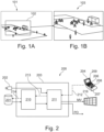
- Figure 1A illustrates an original image 101 captured by the wide angle of view camera.
- the interesting portion of the image 101 is highlighted by a border 102.
- Figure 1B shows a zoomed image 103 of a virtual camera that corresponds to the interesting portion of the image in Figure 1A enclosed by the border 102. Since the zoomed image 103 contains fewer pixels, the image resolution of the zoomed image 103 is accordingly smaller than the image resolution of the original camera image 101.
- the process of creating a virtual camera view is mainly a manual process executed by the user who has to focus his attention on this task. This process involves positioning the focus and defining the zooming level of the virtual camera.
- the virtual camera resolution is lower than the resolution of the original video.
- EP 3 550 823 A1 An alternative approach for providing zoomed images of a playing field is disclosed in EP 3 550 823 A1 , which describes a camera system comprising a static wide angle of view camera and a robotic camera.
- the static wide angle of view camera captures a reference image of a playing field.
- a processing apparatus including an artificial intelligence automatically determines a region of interest in the reference image of the playing field.
- the robotic camera is controlled such that it captures a zoomed image of the region of interest on the playing field with a high image resolution.
- the camera system solves the problems of a manual process and limited quality of the zoomed image.
- the additional robotic camera and its control is expensive.
- the production costs are further increased because the static wide angle of view camera is not appropriate to be used as a broadcast camera but only for the described specific usage.
- the present disclosure suggests a playout device for a broadcast production system comprising a storage device for storing video streams.
- the playout device comprises a user interface for receiving instructions from a user and a processor executing software, which implements a plurality of functionalities of the playout device enabling a user
- the processor is configured to compute a trajectory composed of points defining a center and an associated zoom level of a zoomed virtual camera view for every image frame between the beginning and the end of the video clip.
- the computation of the trajectory and the associated zoom levels is based on the center and associated zoom level of the key points 1 to N and performed such that a smooth movement and zoom behavior of the virtual camera view between the key points 1 to N is achieved.
- the processor is configured to crop every image of the video clip outside the virtual camera view between the beginning and end of the video clip to create a zoomed virtual camera clip.
- the suggested playout device allows creating a zoomed virtual camera view in the manual, semi-automatic or automatic mode from the video stream generated by the wide angle of view camera.
- the zoomed virtual camera view is based on an input video stream captured by a wide angle of view camera that is stored on the storage device. In some use cases close-up cameras are used in addition to capture an interesting scene even closer.
- the user can edit the zoomed virtual camera view until he is satisfied with the result.
- the display device is utilized by the user for the creative process.
- the user interface may be integrated in the playout device or can be part of a separate device.
- the display device is part of a multi-view monitor wall, and the user interface is implemented on the control device connected with the playout device.
- the user can define the beginning and the end of the video clip simply by starting and terminating the process that leads to a zoomed virtual camera clip.
- the notion of a video stream has no defined beginning and end whereas the notion of a video clip relates to a portion of a video stream and is limited by the beginning and the end of the video clip.
- the processor comprises one or several neural network(s), which is or are configured to determine the key points and/or the zoom levels in the video clip.
- At least one of the neural networks is configured to determine regions of interest in the video clip based on saliency detection or object tracking.
- the regions of interest are smaller than images of the downloaded video stream.
- Neural networks have turned out to be very efficient in performing these tasks.
- the processor of the playout device is configured to determine the key points and the associated zoom levels utilizing the determined regions of interest.
- the processor is configured to upscale an image resolution of the cropped image to the original image resolution of the video clip or to a user selectable image resolution.
- the cropped images have different sizes and, therefore, the resolution of the cropped images varies from image to image. Consequently, it is advantageous to upscale the cropped images preferably to the image resolution of the downloaded video stream that has served as input to create to the zoomed virtual camera clip.
- the upscaling is performed by a neural network.
- the processor is configured to apply image improvement algorithms, which assure a high image quality of the zoomed virtual camera clip that meets the expectations of viewers of a sports event.
- the present disclosure suggests a method for playout of a zoomed video stream by a playout device according to the first aspect of the present disclosure.
- the method comprises
- the method is executable for example on the playout device according to the first aspect of the present disclosure. Hence, the method realizes the same advantages that have already been described in the context of the playout device.
- the method further comprises upscaling the image resolution of the cropped images to the original resolution of the downloaded video stream or to a user selectable image resolution.
- the cropped images are smaller than the original image of the input video stream. Therefore, the image resolution of the cropped images is smaller than the original image resolution and varies depending on the applied zoom level. Upscaling the cropped images enhances the quality of the cropped images.
- the method further comprises applying image improvement algorithms on the upscaled images.
- Such image improvement algorithms encompass for example deblurring and denoising of the cropped images.
- the method further comprises displaying the downloaded video stream on a display device. Displaying the downloaded video stream on the display device helps the user to edit the video stream and facilitates the creative process of generating azoomed virtual camera clip.
- the display device is either part of the playout device or integrated in a separate device.
- the method further comprises performing saliency detection or object tracking for determining the regions of interest in the video clip.
- Saliency detection and object tracking have turned out to be efficient to detect regions of interest in the video clip.
- the method further comprises utilizing the detected regions of interest to determine the key points and the associated zoom levels.
- the present disclosure relates to a broadcast system comprising a playout device according to the first aspect of the present disclosure.
- FIG. 2 displays a simplified architecture for a conventional production system 200 for broadcast content.
- Broadcast content (briefly: content) refers to video and/or audio content which are encoded or unencoded signal streams (briefly: signals).
- the production system 200 comprises signal sources such as a storage device 201 and a camera 202 providing signal streams to a playout device 203, which is communicatively connected with the signal sources 201, 202. It is noted that in some for embodiments, the storage device 201 and the camera 202 are connected to the playout device 203 via a wide area network, such as is the case in distributed video production systems where various components of the broadcast system are not located in the same location.
- the playout device 203 is controlled by means of a control device 204, which is equipped with control elements such as buttons 206, a T-bar 207 and a jog dial 208.
- the control elements 206-208 enable an operator to select a video clip stored in the storage device 201 and to define how it is to be replayed.
- the video clip is either displayed on a screen 209 or on a multi-view monitor wall 216.
- the operator can browse through the selected video clip and define entry and exit points for replay (IN and OUT, respectively in Figure 3 ).
- the operator can adjust the replay speed of the video clip.
- the entirety of the information entered by the user into the control device 204 is referred to as replay information.
- the selected video clip can be replayed in slow-motion allowing viewers to watch an interesting scene in greater detail in the time domain.
- the user can select a region of interest in the selected video clip that is replayed as a zoomed image 103 allowing viewers to watch an enlarged/zoomed image of the interesting scene.
- the playout device 203 is capable of enhancing the viewer experience significantly by providing zoomed images of the region of interest and/or by replaying the scenes in the region of interest in slow-motion.
- the playout device 203 accommodates two functional blocks, namely a fetcher 210 and a processor 211.
- the processor 211 receives control commands symbolized by arrow 212.
- the control commands convey the mentioned replay information from the control device 204.
- the processor 211 submits a corresponding command 213 to the fetcher 210 which provides another command 214 to the storage device 201 to request the desired video stream from the storage device 201.
- the storage device 201 transfers the requested video stream as image stream to the fetcher 210, which transfers it to the processor 211.
- the stored video stream is encoded. Therefore, the processor 211 decodes the video stream and generates a corresponding program output stream PO and a multi-view stream MV provided to the multi-view monitor wall 216.
- the multi-view stream MV also contains video streams provided by cameras 202 supplied directly to the processor 211.
- the multi-view monitor wall 216 may also be used to display a video stream edited by the user.
- Figure 3 schematically shows a user interface 300 of the control device 204.
- the user interface 300 is implemented as a combination of the display 209 with physical control elements.
- the user interface 300 is implemented as a combination of a touch screen and physical control elements or completely as a touch screen.
- the user interface 300 enables the user to input control commands controlling the playout device 203.
- the control buttons 206a-c permit the user to select one of the plurality of stored video streams.
- the video clip labeled "REC 3" is selected and displayed in a first window 301 of display device 209.
- a timeline 303 of the displayed video clip is represented in a second window 302 below the first window 301 or on the bottom of window 301.
- jog dial 208 (not shown in Figure 3 ) the user can browse through the selected video stream and define the beginning and the end of a new video clip that contains zoomed images of the stored video clip.
- the beginning and the end (entry and exit points) are labeled as IN and OUT, respectively, on the timeline 303.
- the user manually determines key points KP1-KP5 on the timeline 303 by pressing a button 206f. Five key points are only an example. In other use cases the user determines fewer or more than five key points.
- a cursor C indicates on the timeline 303 the currently displayed image.
- a pointing device (not shown in Figure 3 ) the user chooses a center 304 and a zoom level of a cropped image indicated by a border 306.
- the user controls the zoom level by means of an appropriate input device such as a wheel of a computer mouse to zoom the virtual camera in or out and confirms the key point by pressing the button 206f.
- the processor 211 of the playout device 203 calculates a trajectory 307 of a virtual camera utilizing the confirmed key points every time when one additional key point KP1-KP5 is confirmed.
- the trajectory 307 represents the location of the virtual camera focus corresponding to the center of the zoomed image in all frames of the clip between the beginning IN and the end OUT of the video clip.
- Each point on the trajectory is a triplet (x,y;t) comprising the coordinates x, y of the center of the zoomed image in one image frame and the point in time t when this image frame is displayed. Therefore, the trajectory 307 in Figure 3 indicates how the center of the zoomed image moves on the screen 209 which displays the image frame corresponding to the point in time where the cursor C is positioned and the border 306 of the zoomed image.
- the cursor C is moved along the timeline 303 different image frames and different borders 306 are displayed on the screen 209 while the trajectory 307 remains stable unless at least one of the key points is moved.
- trajectory 307 may be based on a spline interpolation to achieve a smooth and natural movement of the virtual camera.
- other interpolation methods may be used as well.
- a dashed line 308 indicates a naive linear interpolation between key points KP1 and KP2. Such simple interpolation is not preferred because it results in an unnatural movement of the virtual camera.
- the user can review the video clip of the virtual camera displayed on the display 209 or on the multi-view monitor wall 216.
- the user When the user is satisfied with the preview, he confirms it by pressing a button 206e and the playout device 203 creates a zoomed clip and stores it to a server 401 ( Figure 4 ).
- the user By activating a button 206d the user can upload a previously stored video clip.
- an AUTO button 206g to trigger an automatic processing of the selected video clip by a neural network implementing an artificial intelligence unit (short: AI unit) 402 ( Figure 4 ).
- the AI unit 402 is integrated in the processor 211, for instance.
- the AI unit 402 automatically identifies regions of interest in the selected video clip and determines a center of the cropped image and its zoom level for each frame between the beginning and end of the video clip. In this way, the AI unit 402 computes a trajectory 307 of the virtual camera.
- the trajectory 307 connects the center of the zoomed image in each frame of the original video clip.
- the trajectory 307 computed by the AI unit 402 is the same as the manually selected trajectory. It is further assumed without limitation of the generality that key points KP1-KP5 on the trajectory 307 suggested by the AI unit 402 are the same as the manually selected key points KP1-KP5. Depending on the selected video clip, the AI unit 402 may determine fewer or more than five key points.
- the user can preview and edit the automatic suggestion generated by the AI unit 402 by adding and modifying one or several key points similarly to the manual mode described above. Once the user is satisfied with the preview, he confirms it by pressing the button 206e
- the playout device 203 calculates for each image of the original video clip a cropped image with the previously defined center of the image and zoom level.
- the playout device creates a zoomed clip of the virtual camera and stores it to the server 401.
- the server 401 also stores streams directly from cameras 202 to make them available for the user at a later point in time.
- Figure 4 shows a high-level block diagram highlighting functional blocks of the broadcast system 200.
- Figure 4 is limited to those functional blocks, which are involved in the creation of a virtual camera view.
- the server 401 stores a plurality of video clips, which can be offered to a user for selection.
- the server 401 provides the video clip selected by the user that is then processed by the AI unit 402.
- the AI unit 403 has terminated the processing and the user is satisfied with the result, the zoomed clip representing the virtual camera view is restored on the server 401 as a new video clip.
- the server 401 makes the new video available by offering it to other devices involved in the creation of a broadcast program.
- a zoom application 403 running on the control device 204 is associated with the user interface 300 ( Figure 3 ) enabling the user to make his inputs.
- Control commands based on user inputs are transmitted to the AI unit 402.
- the AI unit 402 performs automatic detection of regions of interest in the frames of the selected video clip. After the user has confirmed the preview of a virtual camera clip, the processor 211 creates the zoomed clip. The creation of assumed clip will be explained in further detail in connection with Figure 7 .
- the AI unit 402 analyzes the original camera images of the selected video clip according to two different approaches.
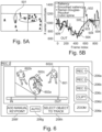
- FIG. 5A illustrates an exemplary saliency detection in an image of a soccer game.
- the salient region is illustrated with an ellipse 501.
- Saliency detection means that those regions in an image are detected where eyes of viewers focus first.
- the result of the salience detection for the entire video clip is shown in a diagram in Figure 5B as a curve 502 indicating the x-position of the salient region for every frame.
- Curve 502 is illustrated as thin solid line.
- a corresponding curve for the y-coordinate exists as well but is not shown in the figures.
- the abscissa of the diagram in Figure 5B represents the frame index of the video clip and the ordinate the x-coordinate of the center of the salient region.
- the curve 502 is filtered or smoothed by advanced filtering techniques to achieve a smoothed curve 503 shown as bold solid line.
- a Ramer-Douglas-Peucker algorithm is applied to the smoothed curve 503 and results in individual points 504 corresponding to key points.
- a spline interpolation is executed on these key points to obtain an interpolated curve 505 shown as dashed line. This process is executed for both the x- and y- coordinate.
- the playout device generates the trajectory of the virtual camera based on object tracking.
- the user selects an object in an image of the original video clip.
- Figure 6 illustrates an image 601 of a playing situation in a soccer game.
- the image 601 shows four players 602a-d.
- a pointing device By means of a pointing device (not shown in Figure 6 ) the user selects player 602a as an object to be tracked.
- the object tracking through all images between the defined beginning IN and end OUT of the stored video clip is achieved by image segmentation and tracking.
- the image segmentation is used to select an object in the image and the tracking follows the selected object through the entire video clip from frame to frame and generates in this way a trajectory of the virtual camera.
- the second approach where the key points are determined by object tracking is only semi-automatic because initially a user input to select the object to be tracked is required. Once the object is manually selected, it is automatically tracked.
- segmentation method for example the commercial product "SegmentAnything” is applicable.
- tracking method for example, the commercial products “TrackAnything” or “deAOTtracker” can be used.
- the present invention is not limited to a specific method for saliency detection, segmentation, and tracking.
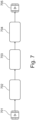
- Figure 7 shows a simplified schematic flow diagram of a method for creating a zoomed clip using the original video clip as input clip, wherein the zoomed video clip has the same image resolution than the input video clip or any other image resolution chosen by the user.
- the input clip is loaded, and a virtual camera view is created.
- the input clip may have different image resolutions for example 8K, 4K, 1080p, 720p etc.
- the images of the input clip are cropped to create the virtual camera clip as it has been explained in connection with Figure 3 .
- the cropped images have different resolutions depending on the size of the cropped area.
- the image resolution of the cropped images is smaller than the image resolution of the input clip.
- the cropped images are rescaled in step 703 by utilizing super-resolution imaging techniques to obtain the original image resolution of the input clip or any other resolution chosen by the user.
- Super resolution imaging techniques per se are known in the art.
- image quality enhancements are applied in step 704 on the cropped and upscaled images to restore image quality that is potentially lost during the processing.
- These image enhancement processes include state-of-the-art technologies such as deblurring and denoising.
- a single unit or device may perform the functions of multiple elements recited in the claims.
- the fact that individual functions and elements are recited in different dependent claims does not mean that a combination of those functions and elements could not advantageously be used.
- List of reference signs 101 original image 401 Server 102 Frame 402 AI unit 103 Cropped image 403 Zoom application 200 Production system 501 Salient region 201 Storage device 502 Curve 202 Camera 503 Smoothed curve 203 Playout device 504 Key points 204 Control device 505 Interpolated curve 206 Control buttons 207 T-bar 208 Jog dial 209 Display 210 Fetcher 601 Image 211 Processor 602 Player 212 Control commands 213 Command 214 Command 216 Multi-view monitor wall 300 User interface 301 first window 302 second window 303 Timeline 304 Center 306 Frame 307 Trajectory 308 Simple trajectory C Cursor KP1-KP5 Key points
Landscapes
- Engineering & Computer Science (AREA)
- Multimedia (AREA)
- Physics & Mathematics (AREA)
- General Physics & Mathematics (AREA)
- Theoretical Computer Science (AREA)
- Signal Processing (AREA)
- Computer Vision & Pattern Recognition (AREA)
- Databases & Information Systems (AREA)
- Human Computer Interaction (AREA)
- Two-Way Televisions, Distribution Of Moving Picture Or The Like (AREA)
- Studio Devices (AREA)
Abstract
Playout device and method for playing out zoomed broadcast content starting from an input video stream captured by a wide angle of view camera. Based on a plurality of key points (KP1-KP5) in the input video stream a center of a zoomed virtual camera view and a corresponding zoom level is either manually selected or automatically determined. These data are used to calculate a trajectory (307) of the virtual camera movement for every image in the input video stream. For creating a zoomed video clip, the images of the input video are cropped outside of the virtual camera view (306).
Description
- The present disclosure relates to a playout device offering zoom capabilities and a method for playing out zoomed broadcast content, in particular video content.
- A playout device is a central piece of technology used in the broadcasting industry for broadcasting content directly to one or several transmission station(s) and to recipients inside the studio, such as the production director or the production team. One person in the production team is tasked with operating the playout device and will be referred to as "user" in the following.
- The playout device enables simultaneously monitoring program content and video streams from various sources such as cameras and storage devices where video clips are stored. Cameras provide video streams either encoded or unencoded while video clips most of the times are stored in encoded format on the storage devices. For the coverage of sports events, it is common to use wide angle of view cameras or even 360° cameras to capture an entire or at least a major part of a playing field, for example a soccer playing field. But sometimes only a smaller portion of the image captured by the wide angle of view camera is interesting. In this case, the user defines a virtual camera by zooming into the original video to create a new video clip. A video clip is a portion of a video stream limited by a beginning and an end.
-
Figure 1A illustrates anoriginal image 101 captured by the wide angle of view camera. The interesting portion of theimage 101 is highlighted by aborder 102.Figure 1B shows azoomed image 103 of a virtual camera that corresponds to the interesting portion of the image inFigure 1A enclosed by theborder 102. Since thezoomed image 103 contains fewer pixels, the image resolution of thezoomed image 103 is accordingly smaller than the image resolution of theoriginal camera image 101. - Existing applications and/or devices for creating virtual cameras suffer at least from two limitations. Firstly, the process of creating a virtual camera view is mainly a manual process executed by the user who has to focus his attention on this task. This process involves positioning the focus and defining the zooming level of the virtual camera. Secondly, the virtual camera resolution is lower than the resolution of the original video. Some applications offer the possibility to upscale the resolution of the virtual camera image. However, conventionally the upscaling is performed by simple methods that degrade image quality of the virtual camera image.
- An alternative approach for providing zoomed images of a playing field is disclosed in
EP 3 550 823 A1 - In view of the limitations of existing solutions for creating a zoomed image of a region of interest by a virtual camera there remains a desire for a playout device to overcome or at least improve one or more of the problems mentioned at the outset.
- According to a first aspect the present disclosure suggests a playout device for a broadcast production system comprising a storage device for storing video streams. The playout device comprises a user interface for receiving instructions from a user and a processor executing software, which implements a plurality of functionalities of the playout device enabling a user
- to select a video stream stored on the storage device for being downloaded into a working memory of the processor and being displayed on a display device,
- to define a beginning and end of a video clip in the downloaded video stream, and
- to either manually select
key points 1 to N and a zoom level associated with thekey points 1 to N in a corresponding number of images between the beginning and the end of the video clip or - to launch an automatic algorithm determining the
key points 1 to N and the zoom level associated with each key point between the beginning and the end of the video clip. - The processor is configured to compute a trajectory composed of points defining a center and an associated zoom level of a zoomed virtual camera view for every image frame between the beginning and the end of the video clip. The computation of the trajectory and the associated zoom levels is based on the center and associated zoom level of the
key points 1 to N and performed such that a smooth movement and zoom behavior of the virtual camera view between thekey points 1 to N is achieved. The processor is configured to crop every image of the video clip outside the virtual camera view between the beginning and end of the video clip to create a zoomed virtual camera clip. - The suggested playout device allows creating a zoomed virtual camera view in the manual, semi-automatic or automatic mode from the video stream generated by the wide angle of view camera. Thus, no additional camera for a zoomed view is necessary. The zoomed virtual camera view is based on an input video stream captured by a wide angle of view camera that is stored on the storage device. In some use cases close-up cameras are used in addition to capture an interesting scene even closer. Regardless of the mode in which the virtual camera view is created, the user can edit the zoomed virtual camera view until he is satisfied with the result. The display device is utilized by the user for the creative process. The user interface may be integrated in the playout device or can be part of a separate device. For instance, in one embodiment the display device is part of a multi-view monitor wall, and the user interface is implemented on the control device connected with the playout device. The user can define the beginning and the end of the video clip simply by starting and terminating the process that leads to a zoomed virtual camera clip. For the sake of explanation, it is noted that the notion of a video stream has no defined beginning and end whereas the notion of a video clip relates to a portion of a video stream and is limited by the beginning and the end of the video clip.
- In an advantageous embodiment of the playout device the processor comprises one or several neural network(s), which is or are configured to determine the key points and/or the zoom levels in the video clip.
- In a preferred embodiment at least one of the neural networks is configured to determine regions of interest in the video clip based on saliency detection or object tracking. The regions of interest are smaller than images of the downloaded video stream. Neural networks have turned out to be very efficient in performing these tasks.
- In a further advantageous development, the processor of the playout device is configured to determine the key points and the associated zoom levels utilizing the determined regions of interest.
- Advantageously the processor is configured to upscale an image resolution of the cropped image to the original image resolution of the video clip or to a user selectable image resolution.
- In a typical use case, the cropped images have different sizes and, therefore, the resolution of the cropped images varies from image to image. Consequently, it is advantageous to upscale the cropped images preferably to the image resolution of the downloaded video stream that has served as input to create to the zoomed virtual camera clip. Optionally, the upscaling is performed by a neural network.
- In a useful embodiment the processor is configured to apply image improvement algorithms, which assure a high image quality of the zoomed virtual camera clip that meets the expectations of viewers of a sports event.
- According to a second aspect, the present disclosure suggests a method for playout of a zoomed video stream by a playout device according to the first aspect of the present disclosure. The method comprises
- selecting a video stream stored on the storage device,
- downloading the selected into a working memory of the processor,
- defining a beginning and end of a video clip in the downloaded video stream, which delimits an input video stream,
- manually or automatically selecting
key points 1 to N and a zoom level associated with thekey points 1 to N in a corresponding number of images between the beginning and the end of the video clip, - computing a trajectory composed of points defining a center and an associated zoom level of a zoomed virtual camera view for every image frame between the beginning and the end of the video clip. The computation of the trajectory and the associated zoom levels is based on the center and associated zoom level of the
key points 1 to N and performed such that a smooth movement and zoom behavior of the virtual camera view between thekey points 1 to N is achieved, and - cropping every image of the video clip outside the virtual camera view between the beginning and end of the video clip to create a zoomed virtual camera clip.
- The method is executable for example on the playout device according to the first aspect of the present disclosure. Hence, the method realizes the same advantages that have already been described in the context of the playout device.
- In one embodiment the method further comprises upscaling the image resolution of the cropped images to the original resolution of the downloaded video stream or to a user selectable image resolution.
- The cropped images are smaller than the original image of the input video stream. Therefore, the image resolution of the cropped images is smaller than the original image resolution and varies depending on the applied zoom level. Upscaling the cropped images enhances the quality of the cropped images.
- In a further development the method further comprises applying image improvement algorithms on the upscaled images.
- Such image improvement algorithms encompass for example deblurring and denoising of the cropped images.
- In a useful embodiment the method further comprises displaying the downloaded video stream on a display device. Displaying the downloaded video stream on the display device helps the user to edit the video stream and facilitates the creative process of generating azoomed virtual camera clip. The display device is either part of the playout device or integrated in a separate device.
- In a preferred embodiment the method further comprises automatically determining regions of interest in the video clip. The regions of interest are smaller than images of the downloaded video stream.
- Automatically determining regions of interest in the video clip for the playout device relieves the user from a significant portion of manual work. Therefore, the user can focus his attention on other tasks of the broadcast production.
- In one embodiment the method further comprises performing saliency detection or object tracking for determining the regions of interest in the video clip.
- Saliency detection and object tracking have turned out to be efficient to detect regions of interest in the video clip.
- In a preferred embodiment the method further comprises utilizing the detected regions of interest to determine the key points and the associated zoom levels.
- According to a third aspect the present disclosure relates to a broadcast system comprising a playout device according to the first aspect of the present disclosure.
- Further advantages will become apparent when reading the detailed description of an embodiment of the present disclosure accompanied by the drawing.
- Exemplary embodiments of the present disclosure are illustrated in the drawings and are explained in more detail in the following description. In the figures, the same or similar elements are referenced with the same or similar reference signs. Object shows:
- Fig. 1A
- an original image of a wide-angle camera view of a playing filed,
- Fig. 1B
- a zoomed portion of the original image of
Fig. 1A , - Fig. 2
- a simplified architecture for a conventional production system,
- Fig. 3
- a user interface of a replay device,
- Fig. 4
- a schematic block diagram of a broadcast system;
- Fig. 5A
- a saliency heat map;
- Fig. 5B
- a saliency diagram of the saliency heat map of
Figure 5A ; - Fig. 6
- an image of a playing situation with a selected object; and
- Fig. 7
- a schematic flow diagram.
-
Figure 2 displays a simplified architecture for aconventional production system 200 for broadcast content. Broadcast content (briefly: content) refers to video and/or audio content which are encoded or unencoded signal streams (briefly: signals). Theproduction system 200 comprises signal sources such as astorage device 201 and acamera 202 providing signal streams to aplayout device 203, which is communicatively connected with thesignal sources storage device 201 and thecamera 202 are connected to theplayout device 203 via a wide area network, such as is the case in distributed video production systems where various components of the broadcast system are not located in the same location. It is further noted that even though only a singleexemplary storage device 201 andcamera 202 are illustrated inFigure 1 , in other embodiments a plurality ofstorage devices 201 andcameras 202 may be present. Theplayout device 203 is controlled by means of acontrol device 204, which is equipped with control elements such asbuttons 206, a T-bar 207 and ajog dial 208. The control elements 206-208 enable an operator to select a video clip stored in thestorage device 201 and to define how it is to be replayed. The video clip is either displayed on ascreen 209 or on amulti-view monitor wall 216. For instance by means of thejog dial 208, the operator can browse through the selected video clip and define entry and exit points for replay (IN and OUT, respectively inFigure 3 ). With the T-bar 207 the operator can adjust the replay speed of the video clip. The entirety of the information entered by the user into thecontrol device 204 is referred to as replay information. For example, the selected video clip can be replayed in slow-motion allowing viewers to watch an interesting scene in greater detail in the time domain. At the same time the user can select a region of interest in the selected video clip that is replayed as a zoomedimage 103 allowing viewers to watch an enlarged/zoomed image of the interesting scene. This is particularly relevant for sports events when critical scenes happen in only a few seconds and/or within a small area in theoriginal image 101 of the wide angle of view camera. This makes it very difficult for viewers to really appreciate the interesting scene in the original camera image. In this regard theplayout device 203 is capable of enhancing the viewer experience significantly by providing zoomed images of the region of interest and/or by replaying the scenes in the region of interest in slow-motion. - To implement this functionality, the
playout device 203 accommodates two functional blocks, namely afetcher 210 and aprocessor 211. Theprocessor 211 receives control commands symbolized byarrow 212. The control commands convey the mentioned replay information from thecontrol device 204. Theprocessor 211 submits acorresponding command 213 to thefetcher 210 which provides anothercommand 214 to thestorage device 201 to request the desired video stream from thestorage device 201. Thestorage device 201 transfers the requested video stream as image stream to thefetcher 210, which transfers it to theprocessor 211. Typically, the stored video stream is encoded. Therefore, theprocessor 211 decodes the video stream and generates a corresponding program output stream PO and a multi-view stream MV provided to themulti-view monitor wall 216. The multi-view stream MV also contains video streams provided bycameras 202 supplied directly to theprocessor 211. Themulti-view monitor wall 216 may also be used to display a video stream edited by the user. -
Figure 3 schematically shows a user interface 300 of thecontrol device 204. In some embodiments the user interface 300 is implemented as a combination of thedisplay 209 with physical control elements. In other embodiments the user interface 300 is implemented as a combination of a touch screen and physical control elements or completely as a touch screen. - The user interface 300 enables the user to input control commands controlling the
playout device 203. Thecontrol buttons 206a-c permit the user to select one of the plurality of stored video streams. In the example shown inFigure 3 the video clip labeled "REC 3" is selected and displayed in afirst window 301 ofdisplay device 209. Atimeline 303 of the displayed video clip is represented in asecond window 302 below thefirst window 301 or on the bottom ofwindow 301. By means of jog dial 208 (not shown inFigure 3 ) the user can browse through the selected video stream and define the beginning and the end of a new video clip that contains zoomed images of the stored video clip. The beginning and the end (entry and exit points) are labeled as IN and OUT, respectively, on thetimeline 303. In a first embodiment the user manually determines key points KP1-KP5 on thetimeline 303 by pressing abutton 206f. Five key points are only an example. In other use cases the user determines fewer or more than five key points. - A cursor C indicates on the
timeline 303 the currently displayed image. With a pointing device (not shown inFigure 3 ) the user chooses acenter 304 and a zoom level of a cropped image indicated by aborder 306. The user controls the zoom level by means of an appropriate input device such as a wheel of a computer mouse to zoom the virtual camera in or out and confirms the key point by pressing thebutton 206f. After two key points have been confirmed, theprocessor 211 of theplayout device 203 calculates atrajectory 307 of a virtual camera utilizing the confirmed key points every time when one additional key point KP1-KP5 is confirmed. Thetrajectory 307 represents the location of the virtual camera focus corresponding to the center of the zoomed image in all frames of the clip between the beginning IN and the end OUT of the video clip. Each point on the trajectory is a triplet (x,y;t) comprising the coordinates x, y of the center of the zoomed image in one image frame and the point in time t when this image frame is displayed. Therefore, thetrajectory 307 inFigure 3 indicates how the center of the zoomed image moves on thescreen 209 which displays the image frame corresponding to the point in time where the cursor C is positioned and theborder 306 of the zoomed image. Thus, when the cursor C is moved along thetimeline 303 different image frames anddifferent borders 306 are displayed on thescreen 209 while thetrajectory 307 remains stable unless at least one of the key points is moved. - The calculation of
trajectory 307 may be based on a spline interpolation to achieve a smooth and natural movement of the virtual camera. However, other interpolation methods may be used as well. A dashedline 308 indicates a naive linear interpolation between key points KP1 and KP2. Such simple interpolation is not preferred because it results in an unnatural movement of the virtual camera. - The user can review the video clip of the virtual camera displayed on the
display 209 or on themulti-view monitor wall 216. When the user is satisfied with the preview, he confirms it by pressing abutton 206e and theplayout device 203 creates a zoomed clip and stores it to a server 401 (Figure 4 ). By activating abutton 206d the user can upload a previously stored video clip. - Alternatively, to automatically determining the key points the user can activate an
AUTO button 206g to trigger an automatic processing of the selected video clip by a neural network implementing an artificial intelligence unit (short: AI unit) 402 (Figure 4 ). TheAI unit 402 is integrated in theprocessor 211, for instance. TheAI unit 402 automatically identifies regions of interest in the selected video clip and determines a center of the cropped image and its zoom level for each frame between the beginning and end of the video clip. In this way, theAI unit 402 computes atrajectory 307 of the virtual camera. Thetrajectory 307 connects the center of the zoomed image in each frame of the original video clip. The automatic identification of regions of interest and the automatic computation of the trajectory will be explained further in greater detail below. - For the sake of simplicity, it is assumed that the
trajectory 307 computed by theAI unit 402 is the same as the manually selected trajectory. It is further assumed without limitation of the generality that key points KP1-KP5 on thetrajectory 307 suggested by theAI unit 402 are the same as the manually selected key points KP1-KP5. Depending on the selected video clip, theAI unit 402 may determine fewer or more than five key points. The user can preview and edit the automatic suggestion generated by theAI unit 402 by adding and modifying one or several key points similarly to the manual mode described above. Once the user is satisfied with the preview, he confirms it by pressing thebutton 206e Theplayout device 203 calculates for each image of the original video clip a cropped image with the previously defined center of the image and zoom level. In this way the playout device creates a zoomed clip of the virtual camera and stores it to theserver 401. For the sake of completeness, it is noted that theserver 401 also stores streams directly fromcameras 202 to make them available for the user at a later point in time. -
Figure 4 shows a high-level block diagram highlighting functional blocks of thebroadcast system 200.Figure 4 is limited to those functional blocks, which are involved in the creation of a virtual camera view. Theserver 401 stores a plurality of video clips, which can be offered to a user for selection. Theserver 401 provides the video clip selected by the user that is then processed by theAI unit 402. Once theAI unit 403 has terminated the processing and the user is satisfied with the result, the zoomed clip representing the virtual camera view is restored on theserver 401 as a new video clip. Theserver 401 makes the new video available by offering it to other devices involved in the creation of a broadcast program. Azoom application 403 running on thecontrol device 204 is associated with the user interface 300 (Figure 3 ) enabling the user to make his inputs. Control commands based on user inputs are transmitted to theAI unit 402. TheAI unit 402 performs automatic detection of regions of interest in the frames of the selected video clip. After the user has confirmed the preview of a virtual camera clip, theprocessor 211 creates the zoomed clip. The creation of assumed clip will be explained in further detail in connection withFigure 7 . - For determining the regions of interest and hence the trajectory of the virtual camera, the
AI unit 402 analyzes the original camera images of the selected video clip according to two different approaches. - According to a first approach, saliency techniques are applied, which are known in the art, for example in https://arxiv.org/pdf/2012.06170.pdf.
Figure 5A illustrates an exemplary saliency detection in an image of a soccer game. The salient region is illustrated with anellipse 501. Saliency detection means that those regions in an image are detected where eyes of viewers focus first. The result of the salience detection for the entire video clip is shown in a diagram inFigure 5B as acurve 502 indicating the x-position of the salient region for every frame.Curve 502 is illustrated as thin solid line. A corresponding curve for the y-coordinate exists as well but is not shown in the figures. The abscissa of the diagram inFigure 5B represents the frame index of the video clip and the ordinate the x-coordinate of the center of the salient region. In a next step thecurve 502 is filtered or smoothed by advanced filtering techniques to achieve a smoothedcurve 503 shown as bold solid line. In a following step a Ramer-Douglas-Peucker algorithm is applied to the smoothedcurve 503 and results inindividual points 504 corresponding to key points. In a final step a spline interpolation is executed on these key points to obtain an interpolatedcurve 505 shown as dashed line. This process is executed for both the x- and y- coordinate. As a result, an interpolated curve is obtained that corresponds to thetrajectory 307, which determines the movement of the virtual camera. This approach has the advantage that the user can edit the key points in the same way regardless of whether the key points were selected manually by the user or automatically determined by theAI unit 402. In this first approach the key points are determined fully automatically. - According to a second approach, the playout device generates the trajectory of the virtual camera based on object tracking. The user selects an object in an image of the original video clip.
Figure 6 illustrates animage 601 of a playing situation in a soccer game. Theimage 601 shows fourplayers 602a-d. By means of a pointing device (not shown inFigure 6 ) the user selectsplayer 602a as an object to be tracked. The object tracking through all images between the defined beginning IN and end OUT of the stored video clip is achieved by image segmentation and tracking. The image segmentation is used to select an object in the image and the tracking follows the selected object through the entire video clip from frame to frame and generates in this way a trajectory of the virtual camera. The second approach where the key points are determined by object tracking is only semi-automatic because initially a user input to select the object to be tracked is required. Once the object is manually selected, it is automatically tracked. - As a segmentation method for example the commercial product "SegmentAnything" is applicable. As tracking method for example, the commercial products "TrackAnything" or "deAOTtracker" can be used. However, it is noted that to the present invention is not limited to a specific method for saliency detection, segmentation, and tracking.
-
Figure 7 shows a simplified schematic flow diagram of a method for creating a zoomed clip using the original video clip as input clip, wherein the zoomed video clip has the same image resolution than the input video clip or any other image resolution chosen by the user. Instep 701 the input clip is loaded, and a virtual camera view is created. The input clip may have different image resolutions for example 8K, 4K, 1080p, 720p etc. Instep 702 the images of the input clip are cropped to create the virtual camera clip as it has been explained in connection withFigure 3 . The cropped images have different resolutions depending on the size of the cropped area. The image resolution of the cropped images is smaller than the image resolution of the input clip. For this reason, the cropped images are rescaled instep 703 by utilizing super-resolution imaging techniques to obtain the original image resolution of the input clip or any other resolution chosen by the user. Super resolution imaging techniques per se are known in the art. In addition to that, image quality enhancements are applied instep 704 on the cropped and upscaled images to restore image quality that is potentially lost during the processing. These image enhancement processes include state-of-the-art technologies such as deblurring and denoising. After these processing steps the zoomed clip is stored instep 705 on theserver 401 and available for other devices in the broadcast production system. - Individual components or functionalities of the present invention are described in the embodiment examples as software or hardware solutions. However, this does not mean that a functionality described as a software solution cannot also be implemented in hard-ware and vice versa. Similarly, mixed solutions are also conceivable for a person skilled in the art, in which components and functionalities are simultaneously partially realized in software and hardware.
- In the claims, the word "comprising" does not exclude other elements or steps, and the indefinite article "a" does not exclude a plurality.
- A single unit or device may perform the functions of multiple elements recited in the claims. The fact that individual functions and elements are recited in different dependent claims does not mean that a combination of those functions and elements could not advantageously be used.
List of reference signs 101 original image 401 Server 102 Frame 402 AI unit 103 Cropped image 403 Zoom application 200 Production system 501 Salient region 201 Storage device 502 Curve 202 Camera 503 Smoothed curve 203 Playout device 504 Key points 204 Control device 505 Interpolated curve 206 Control buttons 207 T- bar 208 Jog dial 209 Display 210 Fetcher 601 Image 211 Processor 602 Player 212 Control commands 213 Command 214 Command 216 Multi-view monitor wall 300 User interface 301 first window 302 second window 303 Timeline 304 Center 306 Frame 307 Trajectory 308 Simple trajectory C Cursor KP1-KP5 Key points
Claims (14)
- Playout device for a broadcast production system (200) comprising a storage device (201) for storing video streams, wherein the playout device (203) comprises a user interface (300) for receiving instructions from a user, and a processor (211) executing software, which implements a plurality of functionalities of the playout device enabling a user- to select a video stream stored on the storage device (201) for being downloaded into a working memory of the processor (211) and being displayed on a display device (209,216),- to define a beginning (IN) and end (OUT) of a video clip in the downloaded video stream, and- to either manually select key points 1 to N (KP1-KP5) and a zoom level associated with the key points 1 to N in a corresponding number of images between the beginning and the end of the video clip or- to launch an automatic algorithm determining the key points 1 to N (KP1-KP5) and the zoom level associated with each key point between the beginning and the end of the video clip,- wherein the processor (211) is configured to compute a trajectory (307) composed of points defining a center (304) and an associated zoom level of a zoomed virtual camera view for every image frame between the beginning (IN) and (OUT) the end of the video clip,- wherein the computation of the trajectory (307) and the associated zoom levels is based on the center and associated zoom level of the key points 1 to N and performed such that a smooth movement of the virtual camera view between the key points 1 to N is achieved, and- wherein the processor is configured to crop every image of the video clip outside the virtual camera view between the beginning and end of the video clip to create a zoomed virtual camera clip.
- Playout device according to claim 1, wherein the processor (211) comprises one or several neural network(s), which is or are configured to determine the key points (KP1-KP5) and/or the zoom levels in the video clip.
- Playout device according to claim 2, wherein at least one of the neural networks is configured to determine regions of interest (501,602a) in the video clip based on saliency detection or object tracking, and wherein the regions of interest are smaller than images of the video clip.
- Playout device according to claim 3, wherein the processor is configured to determine the key points (KP1-KP5) and the associated zoom levels utilizing the determined regions of interest (501,602a).
- Playout device according to one of the preceding claims, wherein the processor is configured to upscale an image resolution of the cropped image to the original image resolution of the downloaded video stream or to a user selectable image resolution.
- Playout device according to claim 1, wherein the processor is configured to apply image improvement algorithms.
- Method for playout of a zoomed video stream by a playout device according to one of the preceding claims, comprising- selecting a video stream stored on the storage device,- downloading the selected into a working memory of the processor,- defining a beginning and end in a video clip in the downloaded video stream, which delimits an input video stream,- manually or automatically selecting key points 1 to N and a zoom level associated with the key points 1 to N in a corresponding number of images between the beginning and the end of the video clip,- computing a trajectory composed of points defining a center and an associated zoom level of a zoomed virtual camera view for every image frame between the beginning and the end of the video clip, wherein the computation of the trajectory and the associated zoom levels is based on the center and associated zoom level of the key points 1 to N and performed such that a smooth movement of the virtual camera view between the key points 1 to N is achieved, and- cropping every image of the video clip outside the virtual camera view between the beginning and end of the video clip to create a zoomed virtual camera clip.
- Method according to claim 7, wherein the method further comprises upscaling the resolution of the cropped images to the original image resolution of the downloaded video stream or to a user selectable image resolution.
- Method according to claim 8, wherein the method further comprises applying image improvement algorithms on the upscaled images.
- Method according to claims 7 to 9, wherein the method further comprises displaying the downloaded video stream on a display device.
- Method according to claims 7 to 10, wherein the method further comprises automatically determining regions of interest in the video clip, wherein the regions of interest are smaller than images of the downloaded video stream.
- Method according to claim 11, wherein the method further comprises performing saliency detection or object tracking for detecting the regions of interest in the video clip.
- Method according to claim 11 or 12, wherein the method further comprises utilizing the detected regions of interest to determine the key points and the associated zoom levels.
- Broadcast system comprising a playout device (203) according to claims 1 to 6.
Priority Applications (2)
| Application Number | Priority Date | Filing Date | Title |
|---|---|---|---|
| EP23197489.0A EP4525465A1 (en) | 2023-09-14 | 2023-09-14 | Playout device and method for playing out zoomed broadcast content |
| US18/882,482 US20250117878A1 (en) | 2023-09-14 | 2024-09-11 | Playout Device and Method for Playing Out Zoomed Broadcast Content |
Applications Claiming Priority (1)
| Application Number | Priority Date | Filing Date | Title |
|---|---|---|---|
| EP23197489.0A EP4525465A1 (en) | 2023-09-14 | 2023-09-14 | Playout device and method for playing out zoomed broadcast content |
Publications (1)
| Publication Number | Publication Date |
|---|---|
| EP4525465A1 true EP4525465A1 (en) | 2025-03-19 |
Family
ID=88068504
Family Applications (1)
| Application Number | Title | Priority Date | Filing Date |
|---|---|---|---|
| EP23197489.0A Pending EP4525465A1 (en) | 2023-09-14 | 2023-09-14 | Playout device and method for playing out zoomed broadcast content |
Country Status (2)
| Country | Link |
|---|---|
| US (1) | US20250117878A1 (en) |
| EP (1) | EP4525465A1 (en) |
Citations (4)
| Publication number | Priority date | Publication date | Assignee | Title |
|---|---|---|---|---|
| US20140164636A1 (en) * | 2012-12-08 | 2014-06-12 | Evertz Microsystems Ltd. | Automatic panning and zooming systems and methods |
| US20170244894A1 (en) * | 2016-02-22 | 2017-08-24 | Seastar Labs, Inc. | Method and Apparatus for Managing Latency of Remote Video Production |
| EP3550823A1 (en) | 2018-04-05 | 2019-10-09 | EVS Broadcast Equipment SA | Automatic control of robotic camera for capturing a portion of a playing field |
| WO2021236296A1 (en) * | 2020-05-20 | 2021-11-25 | Qualcomm Incorporated | Maintaining fixed sizes for target objects in frames |
-
2023
- 2023-09-14 EP EP23197489.0A patent/EP4525465A1/en active Pending
-
2024
- 2024-09-11 US US18/882,482 patent/US20250117878A1/en active Pending
Patent Citations (4)
| Publication number | Priority date | Publication date | Assignee | Title |
|---|---|---|---|---|
| US20140164636A1 (en) * | 2012-12-08 | 2014-06-12 | Evertz Microsystems Ltd. | Automatic panning and zooming systems and methods |
| US20170244894A1 (en) * | 2016-02-22 | 2017-08-24 | Seastar Labs, Inc. | Method and Apparatus for Managing Latency of Remote Video Production |
| EP3550823A1 (en) | 2018-04-05 | 2019-10-09 | EVS Broadcast Equipment SA | Automatic control of robotic camera for capturing a portion of a playing field |
| WO2021236296A1 (en) * | 2020-05-20 | 2021-11-25 | Qualcomm Incorporated | Maintaining fixed sizes for target objects in frames |
Also Published As
| Publication number | Publication date |
|---|---|
| US20250117878A1 (en) | 2025-04-10 |
Similar Documents
| Publication | Publication Date | Title |
|---|---|---|
| US12087330B2 (en) | Masking in video stream | |
| US12381994B2 (en) | Real time video special effects system and method | |
| US20230362482A1 (en) | Assist for orienting a camera at different zoom levels | |
| KR102811359B1 (en) | Real-time video special effects system and method | |
| US20210160435A1 (en) | Fast and/or slow motion compensating timer display | |
| US6081278A (en) | Animation object having multiple resolution format | |
| US6268864B1 (en) | Linking a video and an animation | |
| US6278466B1 (en) | Creating animation from a video | |
| US6362850B1 (en) | Interactive movie creation from one or more still images in a digital imaging device | |
| KR20210092220A (en) | Real-time video special effects systems and methods | |
| US20040027367A1 (en) | Method of and apparatus for processing zoomed sequential images | |
| JP3230858B2 (en) | Video priority automatic selection method and video digest automatic display device | |
| US7388605B2 (en) | Still image capturing of user-selected portions of image frames | |
| KR20190039774A (en) | Apparatus, method and program for information processing relating to generation of virtual viewpoint image | |
| US9703461B2 (en) | Media content creation | |
| US12003882B2 (en) | Information processing devices, methods, and computer-readable medium for performing information processing to output video content using video from multiple video sources including one or more pan-tilt-zoom (PTZ)-enabled network cameras | |
| CN114520877A (en) | Video recording method and device and electronic equipment | |
| US12452383B2 (en) | Fast and/or slow motion compensating timer display | |
| JP2002518723A (en) | Creating animation from video | |
| CN100583999C (en) | Apparatus and method for processing images and apparatus and method for processing reproduced images | |
| US20250117878A1 (en) | Playout Device and Method for Playing Out Zoomed Broadcast Content | |
| KR20160053428A (en) | Operation method of camera apparatus through user interface | |
| EP4503590A1 (en) | Shooting method, apparatus, electronic device and medium | |
| JPH11168685A (en) | Image processing method | |
| US20260141923A1 (en) | Masking in video stream |
Legal Events
| Date | Code | Title | Description |
|---|---|---|---|
| PUAI | Public reference made under article 153(3) epc to a published international application that has entered the european phase |
Free format text: ORIGINAL CODE: 0009012 |
|
| STAA | Information on the status of an ep patent application or granted ep patent |
Free format text: STATUS: THE APPLICATION HAS BEEN PUBLISHED |
|
| AK | Designated contracting states |
Kind code of ref document: A1 Designated state(s): AL AT BE BG CH CY CZ DE DK EE ES FI FR GB GR HR HU IE IS IT LI LT LU LV MC ME MK MT NL NO PL PT RO RS SE SI SK SM TR |
|
| STAA | Information on the status of an ep patent application or granted ep patent |
Free format text: STATUS: REQUEST FOR EXAMINATION WAS MADE |
|
| 17P | Request for examination filed |
Effective date: 20250915 |