EP4525462A1 - Wireless reception device and wireless display system - Google Patents
Wireless reception device and wireless display system Download PDFInfo
- Publication number
- EP4525462A1 EP4525462A1 EP22942810.7A EP22942810A EP4525462A1 EP 4525462 A1 EP4525462 A1 EP 4525462A1 EP 22942810 A EP22942810 A EP 22942810A EP 4525462 A1 EP4525462 A1 EP 4525462A1
- Authority
- EP
- European Patent Office
- Prior art keywords
- wireless
- apl
- data
- image data
- reception device
- Prior art date
- Legal status (The legal status is an assumption and is not a legal conclusion. Google has not performed a legal analysis and makes no representation as to the accuracy of the status listed.)
- Granted
Links
Images




Classifications
-
- H—ELECTRICITY
- H04—ELECTRIC COMMUNICATION TECHNIQUE
- H04N—PICTORIAL COMMUNICATION, e.g. TELEVISION
- H04N21/00—Selective content distribution, e.g. interactive television or video on demand [VOD]
- H04N21/40—Client devices specifically adapted for the reception of or interaction with content, e.g. set-top-box [STB]; Operations thereof
- H04N21/43—Processing of content or additional data, e.g. demultiplexing additional data from a digital video stream; Elementary client operations, e.g. monitoring of home network or synchronising decoder's clock; Client middleware
- H04N21/436—Interfacing a local distribution network, e.g. communicating with another STB or one or more peripheral devices inside the home
- H04N21/4363—Adapting the video stream to a specific local network, e.g. a Bluetooth® network
- H04N21/43637—Adapting the video stream to a specific local network, e.g. a Bluetooth® network involving a wireless protocol, e.g. Bluetooth®, RF or wireless LAN [IEEE 802.11]
-
- H—ELECTRICITY
- H04—ELECTRIC COMMUNICATION TECHNIQUE
- H04B—TRANSMISSION
- H04B17/00—Monitoring; Testing
- H04B17/20—Monitoring; Testing of receivers
- H04B17/23—Indication means, e.g. displays, alarms, audible means
-
- G—PHYSICS
- G06—COMPUTING OR CALCULATING; COUNTING
- G06F—ELECTRIC DIGITAL DATA PROCESSING
- G06F3/00—Input arrangements for transferring data to be processed into a form capable of being handled by the computer; Output arrangements for transferring data from processing unit to output unit, e.g. interface arrangements
- G06F3/14—Digital output to display device ; Cooperation and interconnection of the display device with other functional units
-
- H—ELECTRICITY
- H04—ELECTRIC COMMUNICATION TECHNIQUE
- H04B—TRANSMISSION
- H04B17/00—Monitoring; Testing
- H04B17/30—Monitoring; Testing of propagation channels
- H04B17/309—Measuring or estimating channel quality parameters
- H04B17/318—Received signal strength
-
- H—ELECTRICITY
- H04—ELECTRIC COMMUNICATION TECHNIQUE
- H04N—PICTORIAL COMMUNICATION, e.g. TELEVISION
- H04N21/00—Selective content distribution, e.g. interactive television or video on demand [VOD]
- H04N21/40—Client devices specifically adapted for the reception of or interaction with content, e.g. set-top-box [STB]; Operations thereof
- H04N21/43—Processing of content or additional data, e.g. demultiplexing additional data from a digital video stream; Elementary client operations, e.g. monitoring of home network or synchronising decoder's clock; Client middleware
- H04N21/442—Monitoring of processes or resources, e.g. detecting the failure of a recording device, monitoring the downstream bandwidth, the number of times a movie has been viewed, the storage space available from the internal hard disk
-
- H—ELECTRICITY
- H04—ELECTRIC COMMUNICATION TECHNIQUE
- H04N—PICTORIAL COMMUNICATION, e.g. TELEVISION
- H04N21/00—Selective content distribution, e.g. interactive television or video on demand [VOD]
- H04N21/40—Client devices specifically adapted for the reception of or interaction with content, e.g. set-top-box [STB]; Operations thereof
- H04N21/43—Processing of content or additional data, e.g. demultiplexing additional data from a digital video stream; Elementary client operations, e.g. monitoring of home network or synchronising decoder's clock; Client middleware
- H04N21/442—Monitoring of processes or resources, e.g. detecting the failure of a recording device, monitoring the downstream bandwidth, the number of times a movie has been viewed, the storage space available from the internal hard disk
- H04N21/44209—Monitoring of downstream path of the transmission network originating from a server, e.g. bandwidth variations of a wireless network
-
- G—PHYSICS
- G09—EDUCATION; CRYPTOGRAPHY; DISPLAY; ADVERTISING; SEALS
- G09G—ARRANGEMENTS OR CIRCUITS FOR CONTROL OF INDICATING DEVICES USING STATIC MEANS TO PRESENT VARIABLE INFORMATION
- G09G2320/00—Control of display operating conditions
- G09G2320/10—Special adaptations of display systems for operation with variable images
- G09G2320/103—Detection of image changes, e.g. determination of an index representative of the image change
-
- G—PHYSICS
- G09—EDUCATION; CRYPTOGRAPHY; DISPLAY; ADVERTISING; SEALS
- G09G—ARRANGEMENTS OR CIRCUITS FOR CONTROL OF INDICATING DEVICES USING STATIC MEANS TO PRESENT VARIABLE INFORMATION
- G09G2340/00—Aspects of display data processing
- G09G2340/02—Handling of images in compressed format, e.g. JPEG, MPEG
-
- G—PHYSICS
- G09—EDUCATION; CRYPTOGRAPHY; DISPLAY; ADVERTISING; SEALS
- G09G—ARRANGEMENTS OR CIRCUITS FOR CONTROL OF INDICATING DEVICES USING STATIC MEANS TO PRESENT VARIABLE INFORMATION
- G09G2340/00—Aspects of display data processing
- G09G2340/16—Determination of a pixel data signal depending on the signal applied in the previous frame
-
- G—PHYSICS
- G09—EDUCATION; CRYPTOGRAPHY; DISPLAY; ADVERTISING; SEALS
- G09G—ARRANGEMENTS OR CIRCUITS FOR CONTROL OF INDICATING DEVICES USING STATIC MEANS TO PRESENT VARIABLE INFORMATION
- G09G2350/00—Solving problems of bandwidth in display systems
-
- G—PHYSICS
- G09—EDUCATION; CRYPTOGRAPHY; DISPLAY; ADVERTISING; SEALS
- G09G—ARRANGEMENTS OR CIRCUITS FOR CONTROL OF INDICATING DEVICES USING STATIC MEANS TO PRESENT VARIABLE INFORMATION
- G09G2360/00—Aspects of the architecture of display systems
- G09G2360/16—Calculation or use of calculated indices related to luminance levels in display data
-
- G—PHYSICS
- G09—EDUCATION; CRYPTOGRAPHY; DISPLAY; ADVERTISING; SEALS
- G09G—ARRANGEMENTS OR CIRCUITS FOR CONTROL OF INDICATING DEVICES USING STATIC MEANS TO PRESENT VARIABLE INFORMATION
- G09G2370/00—Aspects of data communication
- G09G2370/16—Use of wireless transmission of display information
Definitions
- the present disclosure relates to a wireless system for transmitting and receiving A/V data wirelessly.
- Digital TV services using wired or wireless communication networks are becoming widespread.
- Digital TV services can provide various services that were not available with existing analog broadcasting services.
- IPTV Internet Protocol Television
- smart TV services which are types of digital TV services, provide interactivity that allows users to actively select the type of program to watch, the viewing time, and the like. Based on this interactivity, IPTV and smart TV services can also provide various additional services, such as Internet search, home shopping, and online games.
- an A/V transmission device transmits a compressed A/V (Audio/Video) signal to an A/V reception device through a wireless connection, and the A/V reception device restores and outputs the compressed A/V signal.
- A/V Audio/Video
- RF Radio Frequency
- the A/V transmission device transmits average picture level (APL) data to the A/V reception device along with a video frame (or video signal).
- APL average picture level
- the purpose of the present disclosure is to generate APL data for an image signal by itself by a wireless reception device when a wireless transmission device cannot receive APL data transmitted by the wireless reception device due to deterioration or disconnection of the wireless signal of a wireless display system.
- the purpose of the present disclosure is to calculate APL data for an image frame by a wireless reception device to output a stable image when the transmission of APL data in a wireless display system is not smooth.
- a wireless reception device may include a display; a memory; an RF (Radio Frequency) reception interface including a plurality of receiving antennas and configured to receive compressed image data from a wireless transmission device; a restoration chip configured to restore the compressed image data; and a microcomputer configured to obtain an average picture level (APL) value of the image data using previous image data or previous APL data stored in the memory and display an image frame having the obtained APL value on the display based on an abnormal state of wireless quality between the wireless transmission device and the wireless reception device being detected.
- RF Radio Frequency
- the wireless transmission device may be configured to transmit compressed image data to the wireless reception device
- the wireless reception device may be configured to obtain an average picture level (APL) value of the image data using previous image data or previous APL data stored in the memory and display an image frame having the obtained APL value based on an abnormal state of wireless quality between the wireless transmission device and the wireless reception device being detected.
- APL average picture level
- a wireless reception device can display a stable image by generating an APL value on its own even in a situation where the wireless quality is poor.
- the video/audio (hereinafter, A/V) transmission device is an intelligent device that adds a computerassisted function to a broadcast reception function, for example, and while remaining faithful to the broadcast reception function, it may have an Internet function, and the like, and may have a more convenient interface such as a manual input device, a touch screen, or a space remote control.
- the device may perform functions such as email, web browsing, banking, or games by connecting to the Internet and a computer with the support of a wired or wireless Internet function.
- a standardized general-purpose OS may be used for these various functions.
- the A/V transmission device described in the present disclosure may perform various user-friendly functions since various applications may be freely added or deleted on, for example, a general-purpose OS kernel.
- FIGS. 1 and 2 are diagrams describing a configuration of a wireless display system according to an embodiment of the present disclosure.
- a wireless display system 1 includes an A/V transmission device 100 and an A/V reception device 200.
- the wireless display system 1 may be a system in which an A/V transmission device 100 wirelessly transmits A/V data to an A/V reception device 200, and the A/V reception device 200 outputs A/V data.
- the A/V transmission device 100 may be a device capable of encoding video and audio and wirelessly transmitting encoded content video and audio.
- the A/V transmission device 100 may be a set-top box.
- the A/V transmission device 100 may be connected to an external device, such as a set-top box or a USB memory.
- the A/V transmission device 100 may transmit a video signal or audio signal received from a connected external device to the A/V reception device 200.
- the A/V reception device 200 may be a display device capable of wirelessly receiving encoded video and audio and performing decoding of the received video and audio.
- the A/V transmission device 100 and the A/V reception device 200 may constitute a video wall display system.
- having a display with a thin bezel plays an important role in visualizing content images.
- the A/V transmission device 100 may determine the type of content image input from the outside, and determine the compression ratio of the content image based on the determined type.
- the compression ratio of the content image may be defined as the ratio of the size of the image data before encoding and the size of the image data after encoding.
- the type of the content image may include a still image type, a general video type, and a game video type.
- the A/V transmission device 100 may compress the content image according to the determined compression ratio, and wirelessly transmit the compressed content image to the A/V reception device 200.
- the A/V reception device 200 may restore the compressed content image received from the A/V transmission device 100 and display the restored content image on the display.
- FIG. 2 is a block diagram illustrating the detailed configuration of the A/V transmission device 100 and the A/V reception device 200.
- the A/V transmission device 100 may include a microphone 110, a wireless communication interface 120, a wired communication interface 130, a memory 140, a compression chip 150, an RF transmission interface 160, and a processor 190.
- the microphone 110 may receive an audio signal and transmit the signal to the processor 190.
- the microphone 110 may receive a voice spoken by a user.
- the wireless communication interface 120 may include one or more of a Wi-Fi module and a Bluetooth module.
- the Wi-Fi module may perform wireless communication with an external device or an A/V reception device 200 through the Wi-Fi standard.
- the Bluetooth module may perform wireless communication through the Bluetooth Low Energy (BLE) standard.
- BLE Bluetooth Low Energy
- the Bluetooth module may perform wireless communication with an external device such as a remote control or the A/V reception device 200 through the Bluetooth Low Energy (BLE) standard.
- BLE Bluetooth Low Energy
- the wireless communication interface 120 may be equipped with a tuner that receives a broadcast signal.
- the wired communication interface 130 may be an interface for wired connection with an external device.
- the wired communication interface 130 may include a plurality of HDMI (High-Definition Multimedia Interface) terminals or USB (Universal Serial Bus) ports.
- the wired communication interface 130 may receive a video signal or an audio signal from the external device.
- the memory 140 may store a program for signal processing and control, and may store a signal-processed video, voice, or data signal.
- the memory 140 may perform a function for temporary storage of an image, voice, or data signal input from the outside, and may store information about a predetermined image through a channel memory function.
- the compression chip 150 may compress an image signal or an audio signal input from the outside, and transmit the compressed signal to the RF transmission interface 160.
- the compression chip 150 may have an encoder for compressing the image signal or the audio signal.
- the RF transmission interface 160 may transmit an A/V signal to an RF reception interface 240 of the A/V reception device 200 through RF Radio Frequency communication.
- the RF transmission interface 160 may include one or more antennas.
- the RF transmission interface 160 may transmit a compressed A/V signal in digital form to the RF reception interface 240.
- the RF transmission interface 160 may transmit an A/V signal to the RF reception interface 240 through one or more channels.
- the processor 190 may control the overall operation of the A/V transmission device 100.
- the processor 190 may be named as a Main System on Chip (Main SoC).
- the processor 190 may also include the compression chip 150.
- the A/V reception device 200 may include a wireless communication interface 210, a wired communication interface 220, the RF reception interface 240, a memory 250, a display 260, a speaker 270, a restoration chip 280, and a microcomputer 290.
- the wireless communication interface 210 may include a Wi-Fi module, a Bluetooth module, and an IR module.
- the Wi-Fi module may perform wireless communication through the Wi-Fi standard.
- the Wi-Fi module may perform wireless communication with an external device or the A/V transmission device 100 through the Wi-Fi standard.
- the Bluetooth module may perform wireless communication through the Bluetooth Low Energy (BLE) standard.
- BLE Bluetooth Low Energy
- the Bluetooth module may perform wireless communication with an external device such as a remote control or an A/V transmission device 100 through the Bluetooth Low Energy (BLE) standard.
- BLE Bluetooth Low Energy
- the IR module may receive a signal from a remote controller300 described later through IR Infrared communication.
- the wired communication interface 220 may be an interface for wired connection with an external device.
- the wired communication interface 220 may include a plurality of HDMI (High-Definition Multimedia Interface) terminals or USB (Universal Serial Bus) ports.
- the wired communication interface 220 may receive a video signal or an audio signal from an external device.
- the RF reception interface 240 may receive a compressed A/V signal from the RF transmission interface 160.
- the RF reception interface 240 may include a plurality of antennas.
- the RF reception interface 240 may be placed at the bottom of the display 260.
- the RF reception interface 240 may include a first antenna module and a second antenna module.
- the first antenna module and the second antenna module may each include a plurality of antennas.
- the RF reception interface 240 may receive a compressed A/V signal in digital form from the RF transmission interface 160 and transmit the received A/V signal to the restoration chip 280.
- the memory 250 may store a program for signal processing and control and may store a signal-processed image, voice, or data signal.
- the display 260 may display an image signal received from the microcomputer 290.
- the display 260 may display an image signal according to the operation of a timing controller not shown.
- the restoration chip 280 may restore the compressed A/V signal received by the RF reception interface 240. To this end, the restoration chip 280 may include a decoder.
- the microcomputer 290 may control the overall operation of the A/V reception device 200.
- the microcomputer 290 may output a restored image signal through a display 260 and output a restored audio signal through a speaker 270.
- FIG. 3 is a block diagram illustrating a configuration of a remote control device according to an embodiment of the present disclosure.
- the remote control device 300 may include a wireless communication interface 310, a user input interface 330, a memory 350, and a controller 390.
- the wireless communication interface 310 may be an interface for performing wireless communication with the A/V transmission device 100 or the A/V reception device 200.
- the wireless communication interface 310 may include a Bluetooth Low Energy (BLE) module 311 and an IR (InfraRed) module 313.
- BLE Bluetooth Low Energy
- IR InfraRed
- the BLE module 311 may transmit a signal to the A/V transmission device 100 for controlling the operation of the A/V transmission device 100.
- the BLE module 311 may transmit a signal to the A/V transmission device 100 to trigger a pairing operation of the A/V transmission device 100.
- the user input interface 330 may include a keypad, a button, a touch pad, or a touch screen.
- the user input interface 330 may generate a control command for controlling the operation of the A/V transmission device 100 or the A/V reception device 200 according to a user's operation command.
- the user input interface 330 has a hard key button
- the user may operate the hard key through a push operation of the hard key button.
- the user input interface 330 may have various types of input means that the user may operate, such as a scroll key or a jog key.
- the memory 350 may store a program for the operation of the controller 390 and may also temporarily store input/output data.
- the controller 390 controls operations related to the application program and, typically, the overall operation of the remote control device 300.
- FIG. 4 is a ladder diagram for describing an operation method of a wireless system according to an embodiment of the present disclosure.
- APL data is described as data that is distinct from image data, but is not limited thereto, and may be data included in the image data.
- the format of an image signal transmitted by the A/V transmission device 100 to the A/V reception device 200 may be Vx1.
- the processor 190 of the A/V transmission device 100 compresses first image data corresponding to a first image frame and first APL data of the first image data through a compression chip 150 (step S401).
- the first APL data may be an APL value of the first image frame to be displayed on the display 260 of the A/V reception device 200.
- the APL value may be defined as an average of the brightness of each part relative to the maximum brightness of the screen.
- the processor 190 may calculate the first APL data based on RGB data of each of a plurality of pixels included in the first image data. For example, the processor 190 may calculate a plurality of brightnesses corresponding to each of the plurality of pixels, and obtain an average value of the plurality of brightnesses as the first APL data.
- the processor 190 may transmit the first APL data including the APL value of the first image data to the A/V reception device 200 together.
- the first image frame may be a frame to be displayed on the display 260 of the A/V reception device 200 by the first image data.
- the processor 190 of the A/V transmission device 100 compresses the first image data and the first AP data to generate a compressed first packet, and transmits the generated first packet to the A/V reception device 200 through the RF transmission interface 160 (step S403).
- the microcomputer 290 of the A/V reception device 200 restores the compressed first packet through the restoration chip 280 (step S405), and outputs the first image frame through the display 260 based on the restored first image data and the first APL data (step S406).
- the display 260 may be an organic light-emitting diode OLED display.
- the display 260 may include a display panel including a plurality of pixels, and each of the plurality of pixels may include an OLED.
- the display 260 may further include a timing controller that controls the operation of a gate driver and a source driver for driving the display panel.
- the timing controller may control the operation timing of the gate driver and the source driver to allow the display panel to output an image.
- the microcomputer 290 may transmit the first APL data to the timing controller, and the timing controller may generate a current value based on the first APL data and provide the generated current value to the display panel. Accordingly, a first image frame having an APL value indicated by the first APL data may be displayed.
- the microcomputer 290 of the A/V reception device 200 stores the first image data or the first APL data corresponding to the first image frame in the memory 250 (step S407).
- the microcomputer 290 may store one or more of the first image data or the first APL data corresponding to the first image frame in the memory 250.
- the first image data stored in the memory 250 may be compressed data for capacity reduction. That is, the memory 250 may store compressed image data rather than restored image data.
- the microcomputer 290 may match the first APL data to the first image data and store it in the memory 250.
- the microcomputer 290 may store the first image data or the first APL data in the memory 250 only for a predetermined period of time. This will be described later.
- the processor 190 of the A/V transmission device 100 compresses the second image data corresponding to the second image frame and the second APL data of the second image frame through the compression chip 150 (step S409).
- the processor 190 of the A/V transmission device 100 compresses the second image data and the second AP data to generate a compressed second packet, and transmits the generated second packet to the A/V reception device 200 through the RF transmission interface 160 (step S411).
- the microcomputer 290 of the A/V reception device 200 restores the compressed second packet through the restoration chip 280 (step S413).
- the microcomputer 290 of the A/V reception device 200 determines whether an abnormal state of wireless quality is detected (step S415).
- the state of wireless quality may include a normal state and an abnormal state.
- the normal state may be a state in which the wireless signal (e.g., a video signal) transmitted from the RF transmission interface 160 to the RF reception interface 240 is not interrupted.
- the abnormal state may be a state in which the wireless signal transmitted from the RF transmission interface 160 to the RF reception interface 240 is interrupted.
- the microcomputer 290 may detect the abnormal state of wireless quality by measuring a signal-to-noise ratio (SNR).
- SNR signal-to-noise ratio
- the SNR may represent a relative ratio of the power of an A/V signal to the power of a noise signal.
- the microcomputer 290 may determine that the wireless quality is abnormal in the case that the SNR value is smaller than a reference value.
- the microcomputer 290 may determine that the wireless quality is normal in the case that the SNR value is greater than or equal to a reference value.
- the microcomputer 290 may detect a state of wireless quality based on a received signal strength indicator (RSSI). The microcomputer 290 may determine the state of wireless quality as normal if the RSSI value is greater than or equal to a preset value.
- RSSI received signal strength indicator
- the microcomputer 290 may determine the state of wireless quality as abnormal in the case that the RSSI value is less than or equal to a preset value.
- the microcomputer 290 may measure the state of wireless quality in accordance with the output cycle of the video frame. For example, in the case that the output cycle of the video frame is 60 fps, the microcomputer 290 may check the wireless quality 60 times per second.
- the microcomputer 290 of the A/V reception device 200 determines that an abnormal state of wireless quality has been detected, the microcomputer obtains the third APL data of the second image frame based on the first image data or the first APL data previously stored in the memory 250 (step S417).
- the microcomputer 290 may obtain the first APL data corresponding to the first image frame received before receiving the second image frame as the APL data corresponding to the second image frame.
- the microcomputer 290 may obtain the APL value of the first image frame as the APL value of the second image frame. In the case that the wireless quality is not good, the microcomputer 290 may use the APL value of the previous image frame as the APL value of the current image frame.
- the microcomputer 290 may obtain the third APL data for the second image frame using the first image data corresponding to the first image frame received before receiving the second image frame.
- the microcomputer 290 may obtain the APL value calculated using the first image data as the APL value of the second image frame. This will be described later.
- the microcomputer 290 of the A/V reception device 200 outputs the second image frame through the display 260 based on the obtained third APL data (step S419).
- the microcomputer 290 transmits the third APL data to the timing controller, and the timing controller may generate a current value based on the third APL data and provide the generated current value to the display panel. Accordingly, the first image frame having the APL value indicated by the third APL data may be displayed on the display 260.
- the APL value of the image frame may be generated so that a stable image may be output.
- the viewer may not feel inconvenience in watching the image even in a situation where the wireless quality is deteriorated.
- the microcomputer 290 of the A/V reception device 200 determines that the abnormal state of the wireless quality is not detected, the microcomputer 290 deletes the first image data or the first APL data previously stored from the memory 250 (step S421).
- the microcomputer 290 may delete one or more of the first image data or the first APL data from the memory 250 for the buffer of the memory 250.
- the microcomputer 290 of the A/V reception device 200 outputs the second image frame through the display 260 based on the restored second APL data (step S423).
- the microcomputer 290 of the A/V reception device 200 stores the second image data or the second APL data corresponding to the second image frame in the memory 250 (step S425).
- FIG. 5 is a diagram describing a process in which an A/V reception device obtains an APL value using image data when an abnormal condition in wireless quality is detected according to an embodiment of the present disclosure.
- FIG. 5 is a diagram describing step S417 of FIG. 4 in detail.
- the microcomputer 290 of the A/V reception device 200 calculates an APL value using an RGB data set included in the first image data stored in the memory 250 (step S501).
- the RGB data set included in the first image data may include a plurality of RGB values corresponding to each of a plurality of pixels constituting the display panel.
- the microcomputer 290 may calculate an average of the plurality of RGB values and obtain the calculated average value as an APL value.
- the first image data stored in the memory 250 may be compressed data.
- the microcomputer 290 may restore the compressed first image data through the restoration chip 280 and calculate the APL value from the restored first image data.
- the microcomputer 290 obtains the calculated APL value as the third APL data corresponding to the second image frame (step S503).
- the A/V reception device 200 may display a stable image by generating the APL value on its own even in a situation where the wireless quality is poor.
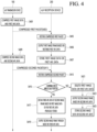
- FIG. 6 is a diagram describing a process in which an A/V reception device obtains an APL value using APL data when an abnormal state of the wireless quality is detected according to one embodiment of the present disclosure.
- FIG. 6 is a diagram describing step S417 of FIG. 4 in detail.
- the microcomputer 290 of the A/V reception device 200 extracts the APL value from the first APL data stored in the memory 250 (step S601).
- the first APL data may include an APL value of the first image frame and identification information identifying the first image frame.
- the identification information may be a time stamp corresponding to the first image frame.
- the microcomputer 290 obtains the extracted APL value as the third APL data of the second image frame (step S603).
- the A/V reception device 200 may generate an APL value on its own even in a situation where the wireless quality is poor, thereby displaying a stable image.
- FIG. 7 is a diagram describing a process of transmitting image data and APL data in a wireless display system according to an embodiment of the present disclosure.
- the wireless display system 1 may include the A/V transmission device 100 and the A/V reception device 200.
- the A/V transmission device 100 may generate image data and APL data, and transmit the generated image data and APL data to the compression chip 150.
- the compression chip 150 may compress the image data and APL data to generate a packet, and transmit the generated packet to the RF transmission interface 160.
- the RF transmission interface 160 may transmit the compressed packet to the RF reception interface 260 through an RF communication band.
- the restoration chip 280 of the A/V reception device 200 may restore the compressed packet, and transmit the restored image data and APL data to the timing controller 261.
- the timing controller 261 may generate a driving signal based on image data and APL data, and output an image frame on the display panel through the generated driving signal.
- the above-described method may be implemented as a code that may be read by a processor on a medium in which a program is recorded.
- Examples of the medium that may be read by a processor include a ROM, a RAM, a CD-ROM, a magnetic tape, a floppy disk, an optical data storage device, etc.
- the display device described above is not limited to the configuration and method of the embodiments described above, and the embodiments may be configured by selectively combining all or part of each embodiment so that various modifications may be made.
Landscapes
- Engineering & Computer Science (AREA)
- Computer Networks & Wireless Communication (AREA)
- Signal Processing (AREA)
- Physics & Mathematics (AREA)
- Multimedia (AREA)
- Electromagnetism (AREA)
- Theoretical Computer Science (AREA)
- Databases & Information Systems (AREA)
- Quality & Reliability (AREA)
- General Engineering & Computer Science (AREA)
- General Physics & Mathematics (AREA)
- Human Computer Interaction (AREA)
- Two-Way Televisions, Distribution Of Moving Picture Or The Like (AREA)
Abstract
Description
- The present disclosure relates to a wireless system for transmitting and receiving A/V data wirelessly.
- Digital TV services using wired or wireless communication networks are becoming widespread. Digital TV services can provide various services that were not available with existing analog broadcasting services.
- For example, IPTV (Internet Protocol Television) and smart TV services, which are types of digital TV services, provide interactivity that allows users to actively select the type of program to watch, the viewing time, and the like. Based on this interactivity, IPTV and smart TV services can also provide various additional services, such as Internet search, home shopping, and online games.
- Recently, TV services are provided through a wireless system in which an A/V transmission device transmits a compressed A/V (Audio/Video) signal to an A/V reception device through a wireless connection, and the A/V reception device restores and outputs the compressed A/V signal.
- In the case of the wireless system, RF (Radio Frequency) communication is performed between the A/V transmission device and the A/V reception device through antennas.
- Conventionally, the A/V transmission device transmits average picture level (APL) data to the A/V reception device along with a video frame (or video signal).
- However, there are cases where the transmission of APL data is not smooth due to obstacles or signal interference in the network environment between the A/V transmission device and the A/V reception device.
- As a result, there is a problem in which the image quality deteriorates, such as flickering, in the A/V reception device because the image frame and the corresponding APL data do not match.
- The purpose of the present disclosure is to generate APL data for an image signal by itself by a wireless reception device when a wireless transmission device cannot receive APL data transmitted by the wireless reception device due to deterioration or disconnection of the wireless signal of a wireless display system.
- The purpose of the present disclosure is to calculate APL data for an image frame by a wireless reception device to output a stable image when the transmission of APL data in a wireless display system is not smooth.
- A wireless reception device according to an aspect of embodiments may include a display; a memory; an RF (Radio Frequency) reception interface including a plurality of receiving antennas and configured to receive compressed image data from a wireless transmission device; a restoration chip configured to restore the compressed image data; and a microcomputer configured to obtain an average picture level (APL) value of the image data using previous image data or previous APL data stored in the memory and display an image frame having the obtained APL value on the display based on an abnormal state of wireless quality between the wireless transmission device and the wireless reception device being detected.
- According to wireless display system including a wireless transmission device and a wireless reception device according to another aspect of embodiments, the wireless transmission device may be configured to transmit compressed image data to the wireless reception device, and the wireless reception device may be configured to obtain an average picture level (APL) value of the image data using previous image data or previous APL data stored in the memory and display an image frame having the obtained APL value based on an abnormal state of wireless quality between the wireless transmission device and the wireless reception device being detected.
- According to an embodiment of the present disclosure, a wireless reception device can display a stable image by generating an APL value on its own even in a situation where the wireless quality is poor.
- Accordingly, a viewer can watch the image without feeling inconvenienced even in a situation where the wireless quality is deteriorated.
-
-
FIGS. 1 and2 are diagrams describing a configuration of a wireless display system according to an embodiment of the present disclosure. -
FIG. 3 is a block diagram illustrating a configuration of a remote control device according to an embodiment of the present disclosure. -
FIG. 4 is a ladder diagram for describing an operation method of a wireless system according to an embodiment of the present disclosure. -
FIG. 5 is a diagram describing a process in which an A/V reception device obtains an APL value using image data when an abnormal condition in wireless quality is detected according to an embodiment of the present disclosure. -
FIG. 6 is a diagram describing a process in which an A/V reception device obtains an APL value using APL data when an abnormal state of the wireless quality is detected according to one embodiment of the present disclosure. -
FIG. 7 is a diagram describing a process of transmitting image data and APL data in a wireless display system according to an embodiment of the present disclosure. - The video/audio (hereinafter, A/V) transmission device according to an embodiment of the present disclosure is an intelligent device that adds a computerassisted function to a broadcast reception function, for example, and while remaining faithful to the broadcast reception function, it may have an Internet function, and the like, and may have a more convenient interface such as a manual input device, a touch screen, or a space remote control.
- In addition, the device may perform functions such as email, web browsing, banking, or games by connecting to the Internet and a computer with the support of a wired or wireless Internet function. A standardized general-purpose OS may be used for these various functions.
- Therefore, the A/V transmission device described in the present disclosure may perform various user-friendly functions since various applications may be freely added or deleted on, for example, a general-purpose OS kernel.
-
FIGS. 1 and2 are diagrams describing a configuration of a wireless display system according to an embodiment of the present disclosure. - Referring to
FIG. 1 , awireless display system 1 according to an embodiment of the present disclosure includes an A/V transmission device 100 and an A/V reception device 200. - The
wireless display system 1 may be a system in which an A/V transmission device 100 wirelessly transmits A/V data to an A/V reception device 200, and the A/V reception device 200 outputs A/V data. - The A/
V transmission device 100 may be a device capable of encoding video and audio and wirelessly transmitting encoded content video and audio. - The A/
V transmission device 100 may be a set-top box. - The A/
V transmission device 100 may be connected to an external device, such as a set-top box or a USB memory. The A/V transmission device 100 may transmit a video signal or audio signal received from a connected external device to the A/V reception device 200. - The A/
V reception device 200 may be a display device capable of wirelessly receiving encoded video and audio and performing decoding of the received video and audio. - The A/
V transmission device 100 and the A/V reception device 200 may constitute a video wall display system. - In a video wall, having a display with a thin bezel plays an important role in visualizing content images. In order to have a thin bezel of the display, it is efficient to have only components that may play a minimum role, and to perform circuits or components for main functions in a separate device.
- The A/
V transmission device 100 may determine the type of content image input from the outside, and determine the compression ratio of the content image based on the determined type. The compression ratio of the content image may be defined as the ratio of the size of the image data before encoding and the size of the image data after encoding. - The type of the content image may include a still image type, a general video type, and a game video type.
- The A/
V transmission device 100 may compress the content image according to the determined compression ratio, and wirelessly transmit the compressed content image to the A/V reception device 200. - The A/
V reception device 200 may restore the compressed content image received from the A/V transmission device 100 and display the restored content image on the display. -
FIG. 2 is a block diagram illustrating the detailed configuration of the A/V transmission device 100 and the A/V reception device 200. - Referring to
FIG. 2 , the A/V transmission device 100 may include amicrophone 110, awireless communication interface 120, awired communication interface 130, amemory 140, acompression chip 150, anRF transmission interface 160, and aprocessor 190. - The
microphone 110 may receive an audio signal and transmit the signal to theprocessor 190. - The
microphone 110 may receive a voice spoken by a user. - The
wireless communication interface 120 may include one or more of a Wi-Fi module and a Bluetooth module. - The Wi-Fi module may perform wireless communication with an external device or an A/
V reception device 200 through the Wi-Fi standard. - The Bluetooth module may perform wireless communication through the Bluetooth Low Energy (BLE) standard.
- The Bluetooth module may perform wireless communication with an external device such as a remote control or the A/
V reception device 200 through the Bluetooth Low Energy (BLE) standard. - The
wireless communication interface 120 may be equipped with a tuner that receives a broadcast signal. - The
wired communication interface 130 may be an interface for wired connection with an external device. Thewired communication interface 130 may include a plurality of HDMI (High-Definition Multimedia Interface) terminals or USB (Universal Serial Bus) ports. - The
wired communication interface 130 may receive a video signal or an audio signal from the external device. - The
memory 140 may store a program for signal processing and control, and may store a signal-processed video, voice, or data signal. - The
memory 140 may perform a function for temporary storage of an image, voice, or data signal input from the outside, and may store information about a predetermined image through a channel memory function. - The
compression chip 150 may compress an image signal or an audio signal input from the outside, and transmit the compressed signal to theRF transmission interface 160. - The
compression chip 150 may have an encoder for compressing the image signal or the audio signal. - The
RF transmission interface 160 may transmit an A/V signal to anRF reception interface 240 of the A/V reception device 200 through RF Radio Frequency communication. - The
RF transmission interface 160 may include one or more antennas. - The
RF transmission interface 160 may transmit a compressed A/V signal in digital form to theRF reception interface 240. - The
RF transmission interface 160 may transmit an A/V signal to theRF reception interface 240 through one or more channels. - The
processor 190 may control the overall operation of the A/V transmission device 100. Theprocessor 190 may be named as a Main System on Chip (Main SoC). - The
processor 190 may also include thecompression chip 150. - The A/
V reception device 200 may include awireless communication interface 210, awired communication interface 220, theRF reception interface 240, amemory 250, adisplay 260, aspeaker 270, arestoration chip 280, and amicrocomputer 290. - The
wireless communication interface 210 may include a Wi-Fi module, a Bluetooth module, and an IR module. - The Wi-Fi module may perform wireless communication through the Wi-Fi standard.
- The Wi-Fi module may perform wireless communication with an external device or the A/
V transmission device 100 through the Wi-Fi standard. - The Bluetooth module may perform wireless communication through the Bluetooth Low Energy (BLE) standard.
- The Bluetooth module may perform wireless communication with an external device such as a remote control or an A/
V transmission device 100 through the Bluetooth Low Energy (BLE) standard. - The IR module may receive a signal from a remote controller300 described later through IR Infrared communication.
- The
wired communication interface 220 may be an interface for wired connection with an external device. Thewired communication interface 220 may include a plurality of HDMI (High-Definition Multimedia Interface) terminals or USB (Universal Serial Bus) ports. - The
wired communication interface 220 may receive a video signal or an audio signal from an external device. - The
RF reception interface 240 may receive a compressed A/V signal from theRF transmission interface 160. - The
RF reception interface 240 may include a plurality of antennas. TheRF reception interface 240 may be placed at the bottom of thedisplay 260. - The
RF reception interface 240 may include a first antenna module and a second antenna module. The first antenna module and the second antenna module may each include a plurality of antennas. - The
RF reception interface 240 may receive a compressed A/V signal in digital form from theRF transmission interface 160 and transmit the received A/V signal to therestoration chip 280. - The
memory 250 may store a program for signal processing and control and may store a signal-processed image, voice, or data signal. - The
display 260 may display an image signal received from themicrocomputer 290. - The
display 260 may display an image signal according to the operation of a timing controller not shown. - The
restoration chip 280 may restore the compressed A/V signal received by theRF reception interface 240. To this end, therestoration chip 280 may include a decoder. - The
microcomputer 290 may control the overall operation of the A/V reception device 200. - The
microcomputer 290 may output a restored image signal through adisplay 260 and output a restored audio signal through aspeaker 270. -
FIG. 3 is a block diagram illustrating a configuration of a remote control device according to an embodiment of the present disclosure. - Referring to
FIG. 3 , theremote control device 300 may include awireless communication interface 310, auser input interface 330, amemory 350, and acontroller 390. - The
wireless communication interface 310 may be an interface for performing wireless communication with the A/V transmission device 100 or the A/V reception device 200. - The
wireless communication interface 310 may include a Bluetooth Low Energy (BLE)module 311 and an IR (InfraRed)module 313. - The
BLE module 311 may transmit a signal to the A/V transmission device 100 for controlling the operation of the A/V transmission device 100. - The
BLE module 311 may transmit a signal to the A/V transmission device 100 to trigger a pairing operation of the A/V transmission device 100. - The
user input interface 330 may include a keypad, a button, a touch pad, or a touch screen. - The
user input interface 330 may generate a control command for controlling the operation of the A/V transmission device 100 or the A/V reception device 200 according to a user's operation command. - In the case that the
user input interface 330 has a hard key button, the user may operate the hard key through a push operation of the hard key button. - The
user input interface 330 may have various types of input means that the user may operate, such as a scroll key or a jog key. - The
memory 350 may store a program for the operation of thecontroller 390 and may also temporarily store input/output data. - The
controller 390 controls operations related to the application program and, typically, the overall operation of theremote control device 300. -
FIG. 4 is a ladder diagram for describing an operation method of a wireless system according to an embodiment of the present disclosure. - Hereinafter, APL data is described as data that is distinct from image data, but is not limited thereto, and may be data included in the image data.
- In addition, hereinafter, the format of an image signal transmitted by the A/
V transmission device 100 to the A/V reception device 200 may be Vx1. - The
processor 190 of the A/V transmission device 100 compresses first image data corresponding to a first image frame and first APL data of the first image data through a compression chip 150 (step S401). - The first APL data may be an APL value of the first image frame to be displayed on the
display 260 of the A/V reception device 200. The APL value may be defined as an average of the brightness of each part relative to the maximum brightness of the screen. - The
processor 190 may calculate the first APL data based on RGB data of each of a plurality of pixels included in the first image data. For example, theprocessor 190 may calculate a plurality of brightnesses corresponding to each of the plurality of pixels, and obtain an average value of the plurality of brightnesses as the first APL data. - When transmitting the first image data, the
processor 190 may transmit the first APL data including the APL value of the first image data to the A/V reception device 200 together. - The first image frame may be a frame to be displayed on the
display 260 of the A/V reception device 200 by the first image data. - The
processor 190 of the A/V transmission device 100 compresses the first image data and the first AP data to generate a compressed first packet, and transmits the generated first packet to the A/V reception device 200 through the RF transmission interface 160 (step S403). - The
microcomputer 290 of the A/V reception device 200 restores the compressed first packet through the restoration chip 280 (step S405), and outputs the first image frame through thedisplay 260 based on the restored first image data and the first APL data (step S406). - In one embodiment, the
display 260 may be an organic light-emitting diode OLED display. Thedisplay 260 may include a display panel including a plurality of pixels, and each of the plurality of pixels may include an OLED. - The
display 260 may further include a timing controller that controls the operation of a gate driver and a source driver for driving the display panel. - The timing controller may control the operation timing of the gate driver and the source driver to allow the display panel to output an image.
- The
microcomputer 290 may transmit the first APL data to the timing controller, and the timing controller may generate a current value based on the first APL data and provide the generated current value to the display panel. Accordingly, a first image frame having an APL value indicated by the first APL data may be displayed. - The
microcomputer 290 of the A/V reception device 200 stores the first image data or the first APL data corresponding to the first image frame in the memory 250 (step S407). - The
microcomputer 290 may store one or more of the first image data or the first APL data corresponding to the first image frame in thememory 250. Here, the first image data stored in thememory 250 may be compressed data for capacity reduction. That is, thememory 250 may store compressed image data rather than restored image data. - The
microcomputer 290 may match the first APL data to the first image data and store it in thememory 250. - The
microcomputer 290 may store the first image data or the first APL data in thememory 250 only for a predetermined period of time. This will be described later. - The
processor 190 of the A/V transmission device 100 compresses the second image data corresponding to the second image frame and the second APL data of the second image frame through the compression chip 150 (step S409). - The
processor 190 of the A/V transmission device 100 compresses the second image data and the second AP data to generate a compressed second packet, and transmits the generated second packet to the A/V reception device 200 through the RF transmission interface 160 (step S411). - The
microcomputer 290 of the A/V reception device 200 restores the compressed second packet through the restoration chip 280 (step S413). - The
microcomputer 290 of the A/V reception device 200 determines whether an abnormal state of wireless quality is detected (step S415). - The state of wireless quality may include a normal state and an abnormal state. The normal state may be a state in which the wireless signal (e.g., a video signal) transmitted from the
RF transmission interface 160 to theRF reception interface 240 is not interrupted. The abnormal state may be a state in which the wireless signal transmitted from theRF transmission interface 160 to theRF reception interface 240 is interrupted. - In one embodiment, the
microcomputer 290 may detect the abnormal state of wireless quality by measuring a signal-to-noise ratio (SNR). - The SNR may represent a relative ratio of the power of an A/V signal to the power of a noise signal.
- The
microcomputer 290 may determine that the wireless quality is abnormal in the case that the SNR value is smaller than a reference value. Themicrocomputer 290 may determine that the wireless quality is normal in the case that the SNR value is greater than or equal to a reference value. - In another embodiment, the
microcomputer 290 may detect a state of wireless quality based on a received signal strength indicator (RSSI). Themicrocomputer 290 may determine the state of wireless quality as normal if the RSSI value is greater than or equal to a preset value. - The
microcomputer 290 may determine the state of wireless quality as abnormal in the case that the RSSI value is less than or equal to a preset value. - In one embodiment, the
microcomputer 290 may measure the state of wireless quality in accordance with the output cycle of the video frame. For example, in the case that the output cycle of the video frame is 60 fps, themicrocomputer 290 may check the wireless quality 60 times per second. - In the case that the
microcomputer 290 of the A/V reception device 200 determines that an abnormal state of wireless quality has been detected, the microcomputer obtains the third APL data of the second image frame based on the first image data or the first APL data previously stored in the memory 250 (step S417). - In one embodiment, in the case that the wireless quality is determined to be abnormal, the
microcomputer 290 may obtain the first APL data corresponding to the first image frame received before receiving the second image frame as the APL data corresponding to the second image frame. - That is, the
microcomputer 290 may obtain the APL value of the first image frame as the APL value of the second image frame. In the case that the wireless quality is not good, themicrocomputer 290 may use the APL value of the previous image frame as the APL value of the current image frame. - In another embodiment, in the case that the wireless quality is determined to be abnormal, the
microcomputer 290 may obtain the third APL data for the second image frame using the first image data corresponding to the first image frame received before receiving the second image frame. - That is, the
microcomputer 290 may obtain the APL value calculated using the first image data as the APL value of the second image frame. This will be described later. - The
microcomputer 290 of the A/V reception device 200 outputs the second image frame through thedisplay 260 based on the obtained third APL data (step S419). - The
microcomputer 290 transmits the third APL data to the timing controller, and the timing controller may generate a current value based on the third APL data and provide the generated current value to the display panel. Accordingly, the first image frame having the APL value indicated by the third APL data may be displayed on thedisplay 260. - In this way, according to the embodiment of the present disclosure, even when the wireless quality between the A/
V transmission device 100 and the A/V reception device 200 is poor, the APL value of the image frame may be generated so that a stable image may be output. - Accordingly, the viewer may not feel inconvenience in watching the image even in a situation where the wireless quality is deteriorated.
- Meanwhile, in the case that the
microcomputer 290 of the A/V reception device 200 determines that the abnormal state of the wireless quality is not detected, themicrocomputer 290 deletes the first image data or the first APL data previously stored from the memory 250 (step S421). - In the case that the
microcomputer 290 determines that the state of the wireless quality is normal, themicrocomputer 290 may delete one or more of the first image data or the first APL data from thememory 250 for the buffer of thememory 250. - The
microcomputer 290 of the A/V reception device 200 outputs the second image frame through thedisplay 260 based on the restored second APL data (step S423). - The
microcomputer 290 of the A/V reception device 200 stores the second image data or the second APL data corresponding to the second image frame in the memory 250 (step S425). - This is to calculate the APL data of the third image frame when the abnormal state in the wireless quality is detected during reception of the third image frame following the second image frame.
-
FIG. 5 is a diagram describing a process in which an A/V reception device obtains an APL value using image data when an abnormal condition in wireless quality is detected according to an embodiment of the present disclosure. -
FIG. 5 is a diagram describing step S417 ofFIG. 4 in detail. - Referring to
FIG. 5 , themicrocomputer 290 of the A/V reception device 200 calculates an APL value using an RGB data set included in the first image data stored in the memory 250 (step S501). - In one embodiment, the RGB data set included in the first image data may include a plurality of RGB values corresponding to each of a plurality of pixels constituting the display panel.
- The
microcomputer 290 may calculate an average of the plurality of RGB values and obtain the calculated average value as an APL value. - In one embodiment, the first image data stored in the
memory 250 may be compressed data. Themicrocomputer 290 may restore the compressed first image data through therestoration chip 280 and calculate the APL value from the restored first image data. - The
microcomputer 290 obtains the calculated APL value as the third APL data corresponding to the second image frame (step S503). - In this way, according to the embodiment of the present disclosure, the A/
V reception device 200 may display a stable image by generating the APL value on its own even in a situation where the wireless quality is poor. -
FIG. 6 is a diagram describing a process in which an A/V reception device obtains an APL value using APL data when an abnormal state of the wireless quality is detected according to one embodiment of the present disclosure. -
FIG. 6 is a diagram describing step S417 ofFIG. 4 in detail. - Referring to
FIG. 6 , themicrocomputer 290 of the A/V reception device 200 extracts the APL value from the first APL data stored in the memory 250 (step S601). - The first APL data may include an APL value of the first image frame and identification information identifying the first image frame. The identification information may be a time stamp corresponding to the first image frame.
- The
microcomputer 290 obtains the extracted APL value as the third APL data of the second image frame (step S603). - In this way, according to the embodiment of the present disclosure, the A/
V reception device 200 may generate an APL value on its own even in a situation where the wireless quality is poor, thereby displaying a stable image. -
FIG. 7 is a diagram describing a process of transmitting image data and APL data in a wireless display system according to an embodiment of the present disclosure. - Referring to
FIG. 7 , thewireless display system 1 may include the A/V transmission device 100 and the A/V reception device 200. - The A/
V transmission device 100 may generate image data and APL data, and transmit the generated image data and APL data to thecompression chip 150. - The
compression chip 150 may compress the image data and APL data to generate a packet, and transmit the generated packet to theRF transmission interface 160. - The
RF transmission interface 160 may transmit the compressed packet to theRF reception interface 260 through an RF communication band. - The
restoration chip 280 of the A/V reception device 200 may restore the compressed packet, and transmit the restored image data and APL data to thetiming controller 261. - The
timing controller 261 may generate a driving signal based on image data and APL data, and output an image frame on the display panel through the generated driving signal. - According to one embodiment of the present disclosure, the above-described method may be implemented as a code that may be read by a processor on a medium in which a program is recorded. Examples of the medium that may be read by a processor include a ROM, a RAM, a CD-ROM, a magnetic tape, a floppy disk, an optical data storage device, etc.
- The display device described above is not limited to the configuration and method of the embodiments described above, and the embodiments may be configured by selectively combining all or part of each embodiment so that various modifications may be made.
Claims (14)
- A wireless reception device, comprising:a display;a memory;an RF (Radio Frequency) reception interface including a plurality of receiving antennas and configured to receive compressed image data from a wireless transmission device;a restoration chip configured to restore the compressed image data; anda microcomputer configured to obtain an average picture level (APL) value of the image data using previous image data or previous APL data stored in the memory and display an image frame having the obtained APL value on the display based on an abnormal state of wireless quality between the wireless transmission device and the wireless reception device being detected.
- The device of claim 1,wherein the previous image data includes a plurality of RGB values corresponding to each of a plurality of pixels constituting the display, andwherein the microcomputer is configured to obtain an average of the plurality of RGB values as the APL value.
- The device of claim 1,
wherein the previous image data is compressed data of a previous image frame received before displaying the image frame. - The device of claim 1,
wherein the previous APL data includes the APL value of a previous image frame received before displaying the image frames. - The device of claim 1,
wherein the microcomputer is configured to delete the previous image data and the previous APL data from the memory after displaying the image frame. - The device of claim 1,
wherein the microcomputer is configured to measure a signal noise ratio (SNR), and detect a state of the wireless quality as the abnormal state based on the measured SNR being less than a reference value. - The device of claim 1,
wherein the microcomputer is configured to measure a received signal strength indicator (RSSI), and detect a state of the wireless quality as the abnormal state when the measured RSSI is less than a reference value. - A wireless display system including a wireless transmission device and a wireless reception device,wherein the wireless transmission device is configured to transmit compressed image data to the wireless reception device, andwherein the wireless reception device is configured to obtain an average picture level (APL) value of the image data using previous image data or previous APL data stored in the memory and display an image frame having the obtained APL value based on an abnormal state of wireless quality between the wireless transmission device and the wireless reception device being detected.
- The system of claim 8,wherein the previous image data includes a plurality of RGB values corresponding to each of a plurality of pixels constituting the display, andwherein the wireless reception device is configured to obtain an average of the plurality of RGB values as the APL value.
- The system of claim 9,
wherein the previous image data is compressed data of a previous image frame received before displaying the image frame. - The system of claim 10,
wherein the previous APL data includes the APL value of a previous image frame received before displaying the image frames. - The system of claim 11,
wherein the wireless reception device is configured to delete the previous image data and the previous APL data from the memory after displaying the image frame. - The system of claim 11,
wherein the wireless reception device is configured to measure a signal noise ratio (SNR), and detect a state of the wireless quality as the abnormal state based on the measured SNR being less than a reference value. - The system of claim 8,
wherein the wireless reception device is configured to measure a received signal strength indicator (RSSI), and detect a state of the wireless quality as the abnormal state when the measured RSSI is less than a reference value.
Applications Claiming Priority (1)
| Application Number | Priority Date | Filing Date | Title |
|---|---|---|---|
| PCT/KR2022/007197 WO2023224146A1 (en) | 2022-05-19 | 2022-05-19 | Wireless reception device and wireless display system |
Publications (3)
| Publication Number | Publication Date |
|---|---|
| EP4525462A1 true EP4525462A1 (en) | 2025-03-19 |
| EP4525462A4 EP4525462A4 (en) | 2025-04-02 |
| EP4525462B1 EP4525462B1 (en) | 2026-04-29 |
Family
ID=88835695
Family Applications (1)
| Application Number | Title | Priority Date | Filing Date |
|---|---|---|---|
| EP22942810.7A Active EP4525462B1 (en) | 2022-05-19 | 2022-05-19 | Wireless reception device and wireless display system |
Country Status (4)
| Country | Link |
|---|---|
| US (1) | US20250323735A1 (en) |
| EP (1) | EP4525462B1 (en) |
| CN (1) | CN119586145A (en) |
| WO (1) | WO2023224146A1 (en) |
Family Cites Families (8)
| Publication number | Priority date | Publication date | Assignee | Title |
|---|---|---|---|---|
| KR0152021B1 (en) * | 1992-12-21 | 1998-12-15 | 윤종용 | Decoding method and apparatus for error correcting of data transmitting |
| US5617333A (en) * | 1993-11-29 | 1997-04-01 | Kokusai Electric Co., Ltd. | Method and apparatus for transmission of image data |
| JP4736487B2 (en) * | 2005-03-22 | 2011-07-27 | 株式会社日立製作所 | Video processing device |
| JP4648071B2 (en) * | 2005-04-28 | 2011-03-09 | 株式会社日立製作所 | Video display device and video signal color saturation control method |
| KR101658138B1 (en) * | 2009-10-07 | 2016-09-21 | 엘지디스플레이 주식회사 | Driving appratus of organic light emitting diode display device and method for driving the same |
| KR101644189B1 (en) * | 2009-12-18 | 2016-08-01 | 엘지디스플레이 주식회사 | Liquid crystal display and dimming controlling method of thereof |
| US12120330B2 (en) * | 2020-08-25 | 2024-10-15 | Lg Electronics Inc. | Image transmission device and image reception device |
| CN112951139B (en) * | 2021-02-08 | 2022-12-06 | 深圳市华星光电半导体显示技术有限公司 | Gray scale adjusting method and device |
-
2022
- 2022-05-19 CN CN202280098250.6A patent/CN119586145A/en active Pending
- 2022-05-19 US US18/867,335 patent/US20250323735A1/en active Pending
- 2022-05-19 EP EP22942810.7A patent/EP4525462B1/en active Active
- 2022-05-19 WO PCT/KR2022/007197 patent/WO2023224146A1/en not_active Ceased
Also Published As
| Publication number | Publication date |
|---|---|
| WO2023224146A1 (en) | 2023-11-23 |
| CN119586145A (en) | 2025-03-07 |
| EP4525462B1 (en) | 2026-04-29 |
| US20250323735A1 (en) | 2025-10-16 |
| EP4525462A4 (en) | 2025-04-02 |
Similar Documents
| Publication | Publication Date | Title |
|---|---|---|
| US7894678B2 (en) | Radio communication device, radio communication system, wireless AV system, radio transmission method, operation control program, and recording medium containing the program | |
| JPWO2002056486A1 (en) | Receiver, mobile terminal, and receiving system | |
| JP2007523531A (en) | Media device | |
| US8248540B2 (en) | Broadcast signal receiving apparatus | |
| EP4525462A1 (en) | Wireless reception device and wireless display system | |
| US12120330B2 (en) | Image transmission device and image reception device | |
| US12388541B2 (en) | Wireless transmitting device and wireless display system | |
| KR101729895B1 (en) | Method for controlling a external device, remote controller and broadcast transmitting apparatus thereof | |
| KR102786766B1 (en) | A/V receiver and wireless display system | |
| KR102721303B1 (en) | Audio/video receiving device and wireless system | |
| US12494185B2 (en) | Wireless transmitting device and wireless display system | |
| KR100939913B1 (en) | Wireless TV System Using Home Network | |
| US20020059600A1 (en) | Digital broadcasting receiver | |
| KR100713277B1 (en) | Connection device for connecting external equipment and TV output method using the same | |
| US12598357B2 (en) | A/V transmitting device and wireless display system | |
| US20250343609A1 (en) | Wireless transmission device and wireless display system | |
| US12294807B2 (en) | A/V receiving apparatus and wireless display system | |
| KR20250159880A (en) | Audio/video transmitting device and wireless display system | |
| US20050266862A1 (en) | Apparatus and method for controlling a portable home theater with multiple functions using a wireless terminal | |
| US7990478B2 (en) | Information presentation apparatus and information presentation method | |
| JP2010041160A (en) | Recorder/reproducer | |
| KR20040000313A (en) | System for recording and reading audiovisual information | |
| KR20110032155A (en) | Broadcast transmitting / receiving method, broadcast receiving apparatus and remote controller using same |
Legal Events
| Date | Code | Title | Description |
|---|---|---|---|
| STAA | Information on the status of an ep patent application or granted ep patent |
Free format text: STATUS: THE INTERNATIONAL PUBLICATION HAS BEEN MADE |
|
| PUAI | Public reference made under article 153(3) epc to a published international application that has entered the european phase |
Free format text: ORIGINAL CODE: 0009012 |
|
| STAA | Information on the status of an ep patent application or granted ep patent |
Free format text: STATUS: REQUEST FOR EXAMINATION WAS MADE |
|
| 17P | Request for examination filed |
Effective date: 20241209 |
|
| AK | Designated contracting states |
Kind code of ref document: A1 Designated state(s): AL AT BE BG CH CY CZ DE DK EE ES FI FR GB GR HR HU IE IS IT LI LT LU LV MC MK MT NL NO PL PT RO RS SE SI SK SM TR |
|
| A4 | Supplementary search report drawn up and despatched |
Effective date: 20250227 |
|
| RIC1 | Information provided on ipc code assigned before grant |
Ipc: H04N 5/57 20060101ALI20250221BHEP Ipc: H04N 5/20 20060101ALI20250221BHEP Ipc: H04N 21/647 20110101ALI20250221BHEP Ipc: H04N 21/442 20110101ALI20250221BHEP Ipc: H04N 21/4363 20110101ALI20250221BHEP Ipc: H04N 21/436 20110101AFI20250221BHEP |
|
| DAV | Request for validation of the european patent (deleted) | ||
| DAX | Request for extension of the european patent (deleted) | ||
| STAA | Information on the status of an ep patent application or granted ep patent |
Free format text: STATUS: EXAMINATION IS IN PROGRESS |
|
| 17Q | First examination report despatched |
Effective date: 20250918 |
|
| GRAP | Despatch of communication of intention to grant a patent |
Free format text: ORIGINAL CODE: EPIDOSNIGR1 |
|
| STAA | Information on the status of an ep patent application or granted ep patent |
Free format text: STATUS: GRANT OF PATENT IS INTENDED |
|
| INTG | Intention to grant announced |
Effective date: 20251126 |
|
| GRAS | Grant fee paid |
Free format text: ORIGINAL CODE: EPIDOSNIGR3 |
|
| GRAA | (expected) grant |
Free format text: ORIGINAL CODE: 0009210 |
|
| STAA | Information on the status of an ep patent application or granted ep patent |
Free format text: STATUS: THE PATENT HAS BEEN GRANTED |
|
| AK | Designated contracting states |
Kind code of ref document: B1 Designated state(s): AL AT BE BG CH CY CZ DE DK EE ES FI FR GB GR HR HU IE IS IT LI LT LU LV MC MK MT NL NO PL PT RO RS SE SI SK SM TR |
|
| REG | Reference to a national code |
Ref country code: CH Ref legal event code: F10 Free format text: ST27 STATUS EVENT CODE: U-0-0-F10-F00 (AS PROVIDED BY THE NATIONAL OFFICE) Effective date: 20260429 |