EP4525418A1 - Electronic device - Google Patents
Electronic device Download PDFInfo
- Publication number
- EP4525418A1 EP4525418A1 EP23802734.6A EP23802734A EP4525418A1 EP 4525418 A1 EP4525418 A1 EP 4525418A1 EP 23802734 A EP23802734 A EP 23802734A EP 4525418 A1 EP4525418 A1 EP 4525418A1
- Authority
- EP
- European Patent Office
- Prior art keywords
- channel
- opening
- sub
- housing
- electronic device
- Prior art date
- Legal status (The legal status is an assumption and is not a legal conclusion. Google has not performed a legal analysis and makes no representation as to the accuracy of the status listed.)
- Pending
Links
Images


Classifications
-
- H—ELECTRICITY
- H04—ELECTRIC COMMUNICATION TECHNIQUE
- H04R—LOUDSPEAKERS, MICROPHONES, GRAMOPHONE PICK-UPS OR LIKE ACOUSTIC ELECTROMECHANICAL TRANSDUCERS; ELECTRIC HEARING AIDS; PUBLIC ADDRESS SYSTEMS
- H04R1/00—Details of transducers, loudspeakers or microphones
- H04R1/02—Casings; Cabinets ; Supports therefor; Mountings therein
- H04R1/028—Casings; Cabinets ; Supports therefor; Mountings therein associated with devices performing functions other than acoustics, e.g. electric candles
-
- H—ELECTRICITY
- H04—ELECTRIC COMMUNICATION TECHNIQUE
- H04R—LOUDSPEAKERS, MICROPHONES, GRAMOPHONE PICK-UPS OR LIKE ACOUSTIC ELECTROMECHANICAL TRANSDUCERS; ELECTRIC HEARING AIDS; PUBLIC ADDRESS SYSTEMS
- H04R1/00—Details of transducers, loudspeakers or microphones
- H04R1/20—Arrangements for obtaining desired frequency or directional characteristics
- H04R1/22—Arrangements for obtaining desired frequency or directional characteristics for obtaining desired frequency characteristic only
- H04R1/28—Transducer mountings or enclosures modified by provision of mechanical or acoustic impedances, e.g. resonator, damping means
- H04R1/2869—Reduction of undesired resonances, i.e. standing waves within enclosure, or of undesired vibrations, i.e. of the enclosure itself
- H04R1/2884—Reduction of undesired resonances, i.e. standing waves within enclosure, or of undesired vibrations, i.e. of the enclosure itself by means of the enclosure structure, i.e. strengthening or shape of the enclosure
- H04R1/2888—Reduction of undesired resonances, i.e. standing waves within enclosure, or of undesired vibrations, i.e. of the enclosure itself by means of the enclosure structure, i.e. strengthening or shape of the enclosure for loudspeaker transducers
-
- H—ELECTRICITY
- H04—ELECTRIC COMMUNICATION TECHNIQUE
- H04M—TELEPHONIC COMMUNICATION
- H04M1/00—Substation equipment, e.g. for use by subscribers
- H04M1/02—Constructional features of telephone sets
- H04M1/0202—Portable telephone sets, e.g. cordless phones, mobile phones or bar type handsets
- H04M1/0279—Improving the user comfort or ergonomics
- H04M1/0283—Improving the user comfort or ergonomics for providing a decorative aspect, e.g. customization of casings, exchangeable faceplate
-
- H—ELECTRICITY
- H04—ELECTRIC COMMUNICATION TECHNIQUE
- H04M—TELEPHONIC COMMUNICATION
- H04M1/00—Substation equipment, e.g. for use by subscribers
- H04M1/02—Constructional features of telephone sets
- H04M1/03—Constructional features of telephone transmitters or receivers, e.g. telephone hand-sets
-
- H—ELECTRICITY
- H04—ELECTRIC COMMUNICATION TECHNIQUE
- H04M—TELEPHONIC COMMUNICATION
- H04M1/00—Substation equipment, e.g. for use by subscribers
- H04M1/02—Constructional features of telephone sets
- H04M1/18—Telephone sets specially adapted for use in ships, mines, or other places exposed to adverse environment
-
- H—ELECTRICITY
- H04—ELECTRIC COMMUNICATION TECHNIQUE
- H04R—LOUDSPEAKERS, MICROPHONES, GRAMOPHONE PICK-UPS OR LIKE ACOUSTIC ELECTROMECHANICAL TRANSDUCERS; ELECTRIC HEARING AIDS; PUBLIC ADDRESS SYSTEMS
- H04R1/00—Details of transducers, loudspeakers or microphones
- H04R1/02—Casings; Cabinets ; Supports therefor; Mountings therein
- H04R1/025—Arrangements for fixing loudspeaker transducers, e.g. in a box, furniture
-
- H—ELECTRICITY
- H05—ELECTRIC TECHNIQUES NOT OTHERWISE PROVIDED FOR
- H05K—PRINTED CIRCUITS; CASINGS OR CONSTRUCTIONAL DETAILS OF ELECTRIC APPARATUS; MANUFACTURE OF ASSEMBLAGES OF ELECTRICAL COMPONENTS
- H05K5/00—Casings, cabinets or drawers for electric apparatus
- H05K5/02—Details
- H05K5/0213—Venting apertures; Constructional details thereof
-
- H—ELECTRICITY
- H04—ELECTRIC COMMUNICATION TECHNIQUE
- H04R—LOUDSPEAKERS, MICROPHONES, GRAMOPHONE PICK-UPS OR LIKE ACOUSTIC ELECTROMECHANICAL TRANSDUCERS; ELECTRIC HEARING AIDS; PUBLIC ADDRESS SYSTEMS
- H04R2499/00—Aspects covered by H04R or H04S not otherwise provided for in their subgroups
- H04R2499/10—General applications
- H04R2499/11—Transducers incorporated or for use in hand-held devices, e.g. mobile phones, PDA's, camera's
Definitions
- This application relates to the field of electronic product technologies, and specifically, to an electronic device.
- An existing electronic device usually includes a large quantity of electric components. Because some electric components need to be communicated with an external environment, a housing of the electronic device needs to be provided with a corresponding breather hole, so that the electric components are communicated with the external environment through the breather hole. However, when there are many electric components needing to be communicated with the external environment in the electronic device, a large quantity of breather holes need to be provided on the housing of the electronic device. Consequently, overall waterproof performance and beauty of the electronic device deteriorate.
- This application provides an electronic device to improve overall waterproof performance and beauty of the electronic device.
- Embodiments of this application provide an electronic device, including: a housing, where the housing is provided with a first opening, and the housing is provided with a first channel and a second channel;
- the barometer and the first acoustic module share the first opening, so that a ventilation requirement of two components can be met by providing only one opening on the housing. In this way, a quantity of openings on the housing in the electronic device can be reduced, thereby improving overall waterproof performance and beauty of the electronic device.
- first and second are used to distinguish between similar objects but do not indicate a particular order or sequence. It is to be understood that the terms used in such ways are interchangeable under appropriate circumstances, so that the embodiments of this application can be implemented in sequences other than those illustrated or described herein.
- the objects distinguished by “first, “second”, and the like are usually of the same type, and a quantity of objects is not limited. For example, there may be one or a plurality of first objects.
- “and/or” used in this specification and the claims indicates at least one of the connected objects. The character “/” generally indicates an "or" relationship between associated objects.
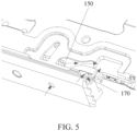
- FIG. 1 to FIG. 5 are diagrams of inner structures of an electronic device according to an embodiment of this application.
- the electronic device includes:
- the first acoustic module 200 may be any acoustic module that needs to be communicated with an external environment in the electronic device, for example, may be an acoustic module such as a microphone, a speaker, or a telephone receiver.
- the first opening 110 may be an opening such as a sound outlet hole or a sound slot.
- the first acoustic module 200 can be communicated with the external environment.
- atmospheric pressure at the barometer 300 is basically the same as atmospheric pressure outside the electronic device.
- an atmospheric pressure value detected by the barometer 300 installed in the housing 100 may be viewed as the environment atmospheric pressure outside the electronic device.
- a current altitude of the electronic device can be determined based on the atmospheric pressure value, and the atmospheric pressure value and the altitude can be output by using a display screen of the electronic device.
- the housing 100 may include a first installation position 120 configured to install the first acoustic module 200.
- the first installation position 120 may include a first air intake vent chamber.
- the first channel 140 may communicate the first air intake vent chamber with the first opening 110, and a ventilation end of the first acoustic module 200 is located in the first air intake vent chamber to communicate the first acoustic module 200 with the external environment.
- the housing 100 may include a second installation position 130 configured to install the barometer 300.
- the second installation position 130 may include a second air intake vent chamber.
- the second channel 150 may communicate the second air intake vent chamber with the first opening 110, and a detection end of the barometer 300 is located in the second air intake vent chamber to communicate the barometer 300 with the external environment.
- first channel 140 and the second channel 150 may be two channels independent of each other. In this way, interference with atmospheric pressure of air in the second channel 150 can be prevented when there is a vibration signal in the first channel 140, thereby improving accuracy of a detection result output by the barometer 300.
- the first opening 110 is provided on an outer surface of the housing 100.
- the first installation position 120, the second installation position 130, the first channel 140, and the second channel 150 may be provided on an installation bracket in the housing 100, for example, may be provided on a mainboard cover of the electronic device.
- the direction indicated by arrows in FIG. 2 is: Outside air flows from the first opening 110 through the first channel 140 and the second channel 150 separately to the first acoustic module 200 and the barometer 300.
- the barometer 300 and the first acoustic module 200 share the first opening 110, so that a ventilation requirement of two components can be met by providing only one opening on the housing 100. In this way, a quantity of openings on the housing 100 in the electronic device can be reduced, thereby improving overall waterproof performance and beauty of the electronic device.
- the first channel 140 comprises a first ventilation chamber 141 and a first sub channel 142
- the first sub channel 142 communicates the first acoustic module 200 with the first ventilation chamber 141
- the first opening 110 is communicated with the first ventilation chamber 141.
- the second channel 150 is communicated with the first ventilation chamber 141 to communicate the barometer 300 with the first opening 110.
- the first opening 110 is a through hole extending from an outer wall of the housing 100 to an inner wall of the first ventilation chamber 141.
- the air entering the first ventilation chamber 141 may be divided into two branches which separately flow into the first sub channel 142 and the second channel 150.
- a sound signal output by the first acoustic module 200 may sequentially passes through the first sub channel 142, the first ventilation chamber 141, and the first opening 110, and is delivered to the outside of the electronic device.
- the first channel 140 includes the first ventilation chamber 141 and the first sub channel 142, and the first sub channel 142, the second channel 150, and the first opening 110 are separately communicated with the first ventilation chamber 141.
- the first acoustic module 200 and the barometer 300 can be separately communicated with the outside by providing only one opening.
- the air entering the first ventilation chamber 141 can be divided into two branches which separately flow into the first sub channel 142 and the second channel 150, the air entering the first sub channel 142 is relatively isolated from the air entering the second channel 150, thereby preventing the first acoustic module 200 from interfering with a detection process of the barometer 300.
- the second channel 150 includes a second ventilation chamber 151 and a second sub channel 152, and the barometer 300 is communicated with the second ventilation chamber 151 through the second sub channel 152.
- the housing 100 is internally provided with a first partition board 160 located between the first ventilation chamber 141 and the second ventilation chamber 151, the first partition board 160 is provided with a breather hole, and the first ventilation chamber 141 is communicated with the second ventilation chamber 151 through the breather hole.
- the first ventilation chamber 141 is isolated from the second ventilation chamber 151 by using the partition board, and the breather hole is provided on the partition board.
- the first acoustic module 200 and the barometer 300 can be separately communicated with the outside by providing only one opening.
- an isolation effect between the first sub channel 142 and the second sub channel 152 can further be improved.
- the first ventilation chamber 141 is a strip-shaped chamber extending along a first direction
- the first sub channel 142 is a strip-shaped channel located in a first plane
- the first direction is set in an angle to the first plane.
- the first ventilation chamber 141 includes a first open end and a first closed end, the first open end is opposite to the first closed end, the first ventilation chamber 141 is communicated with a first end of the first sub channel 142 through the first open end, and a second end of the first sub channel 142 is oriented towards the first acoustic module 200.
- a distance between the breather hole and the first closed end is less than a distance between the breather hole and the first open end.
- the distance between the breather hole and the second closed end less than the distance between the breather hole and the first open end
- the distance between the breather hole and the first open end can be increased.
- the breather hole and the first open end are respectively air intake vents of the second channel 150 and the first sub channel 142. Therefore, by increasing the distance between the breather hole and the first open end, isolation between the second channel 150 and the first sub channel 142 can further be improved.
- the second ventilation chamber 151 is a strip-shaped chamber extending along the first direction, and the second sub channel 152 is a strip-shaped channel located in the first plane.
- the second ventilation chamber 151 includes a second open end and a second closed end, the second open end is opposite to the second closed end, the second ventilation chamber 151 is communicated with a first end of the second sub channel 152 through the second open end, and a second end of the second sub channel 152 is oriented towards the barometer 300.
- a distance between the breather hole and the second closed end is less than a distance between the breather hole and the second open end.
- first direction may be in any angle to the first plane.
- first direction is perpendicular to the first plane.
- the first direction is set perpendicular to the first plane, so that when signals transmitted in the second channel 150 include a vibration signal, and when the vibration signal flows through a joint of the second ventilation chamber 151 and the second sub channel 152, the vibration signal has a significant attenuation because of blocking of the inner wall of the second sub channel 152, thereby further improving accuracy of a detection result of the barometer 300.
- the electronic device further includes a second acoustic module 400, the second acoustic module 400 is disposed in the housing 100, the housing 100 is further provided with a fourth channel 180, and the fourth channel 180 communicates the second acoustic module 400 with the second opening 190.
- outside air flows from the first opening 110 through the second channel 150 to the barometer 300, and outside air flows from the second opening 190 through the third channel 170 to the barometer 300.
- the barometer 300 and the first acoustic module 200 share the first opening 110. Moreover, the barometer 300 is communicated with the second opening 190 through the third channel 170. In this way, the barometer 300 may be communicated with the outside separately through the first opening 110 and the second opening 190, thereby further ensuring good ventilation performance of the barometer 300, and helping improve the accuracy of the detection result of the barometer 300.
- the electronic device further includes a second acoustic module 400, the second acoustic module 400 is disposed in the housing 100, the housing 100 is further provided with a fourth channel 180, and the fourth channel 180 communicates the second acoustic module 400 with the second opening 190.
- the second acoustic module 400 and the first acoustic module 200 are different acoustic modules in the electronic device, and the second acoustic module 400 may be any acoustic module that needs to be communicated with the external environment in the electronic device, for example, may be an acoustic module such as a microphone, a speaker, or a telephone receiver.
- the second opening 190 may be an opening such as a sound outlet hole or a sound slot.
- the barometer 300 and the first acoustic module 200 share the first opening 110.
- the barometer 300 and the second acoustic module 400 share the second opening 190.
- the barometer 300 may be communicated with the outside separately through the first opening 110 and the second opening 190, thereby further ensuring good ventilation performance of the barometer 300, and helping improve the accuracy of the detection result of the barometer 300.
- the second opening 190 is a strip-shaped gap formed in the housing 100
- a second partition board 192 is disposed in the strip-shaped gap
- the second partition board 192 divides the strip-shaped gap into a first sub gap 191 and a second sub gap 193
- the third channel 170 communicates the barometer 300 with the first sub gap 191
- the fourth channel 180 communicates the third installation position with the second sub gap 193.
- the strip-shaped gap may be a sound slot of the electronic device.
- the strip-shaped gap is divided into the first sub gap 191 and the second sub gap 193
- the third channel 170 communicates the barometer 300 with the first sub gap 191
- the fourth channel 180 communicates the third installation position with the second sub gap 193.
- the barometer 300 and the second acoustic module 400 can share the strip-shaped gap.
- the third channel 170 can be relatively isolated from the fourth channel 180, preventing a signal transmitted in the fourth channel 180 from affecting atmospheric pressure in the third channel 170, and helping improve the accuracy of the detection result of the barometer 300.
- an opening area of the first sub gap 191 is less than an opening area of the second sub gap 193.
- a ventilation volume of the barometer 300 can be increased. Moreover, a problem, caused by an excessively small opening area of the second sub gap 193, of an insufficient ventilation volume of the second acoustic module 400 can be avoided.
- the strip-shaped gap comprises a first segment, a second segment 1931, and a third segment 1932
- the second segment 1931 is located between the first segment and the third segment 1932
- the first segment forms the first sub gap 191
- the second segment 1931 and the third segment 1932 form the second sub gap 193
- the fourth channel 180 communicates the third installation position with the third segment 1932.
- the third channel 170 is communicated with the first segment
- the fourth channel 180 is communicated with the third segment 1932. Because the second segment 1931 is located between the first segment and the third segment 1932, a distance between an air intake vent of the third channel 170 and an air intake vent of the fourth channel 180 can be increased effectively, thereby further improving the isolation between the third channel 170 and the fourth channel 180.
- the term "comprise”, “include”, or any other variants thereof are intended to encompass in a non-exclusive mode, so that a process, a method, an object, or an apparatus including a series of elements not only includes those elements, but also includes other elements that are not explicitly listed, or elements that are inherent to such a process, a method, an object, or an apparatus.
- An element defined by the phrase “including a " does not exclude the presence of the same element in the process, method, object, or apparatus including the element, without more restrictions.
Landscapes
- Engineering & Computer Science (AREA)
- Signal Processing (AREA)
- Physics & Mathematics (AREA)
- Acoustics & Sound (AREA)
- Health & Medical Sciences (AREA)
- Otolaryngology (AREA)
- Microelectronics & Electronic Packaging (AREA)
- Measuring Fluid Pressure (AREA)
Abstract
Description
- This application claims priority to
Chinese Patent Application No. 202210491715.6 filed on May 07, 2022 - This application relates to the field of electronic product technologies, and specifically, to an electronic device.
- An existing electronic device usually includes a large quantity of electric components. Because some electric components need to be communicated with an external environment, a housing of the electronic device needs to be provided with a corresponding breather hole, so that the electric components are communicated with the external environment through the breather hole. However, when there are many electric components needing to be communicated with the external environment in the electronic device, a large quantity of breather holes need to be provided on the housing of the electronic device. Consequently, overall waterproof performance and beauty of the electronic device deteriorate.
- This application provides an electronic device to improve overall waterproof performance and beauty of the electronic device.
- Embodiments of this application provide an electronic device, including: a housing, where the housing is provided with a first opening, and the housing is provided with a first channel and a second channel;
- a first acoustic module, where the first acoustic module is disposed in the housing, the first channel communicates the first acoustic module with the first opening; and
- a barometer, where the barometer is disposed in the housing, and the second channel communicates the barometer with the first opening.
- In embodiments of this application, the barometer and the first acoustic module share the first opening, so that a ventilation requirement of two components can be met by providing only one opening on the housing. In this way, a quantity of openings on the housing in the electronic device can be reduced, thereby improving overall waterproof performance and beauty of the electronic device.
-
-
FIG. 1 is a first diagram of an inner structure of an electronic device according to an embodiment of this application; -
FIG. 2 is a second diagram of an inner structure of an electronic device according to an embodiment of this application; -
FIG. 3 is a third diagram of an inner structure of an electronic device according to an embodiment of this application; -
FIG. 4 is a fourth diagram of an inner structure of an electronic device according to an embodiment of this application; and -
FIG. 5 is a fifth diagram of an inner structure of an electronic device according to an embodiment of this application. - The following clearly describes technical solutions in embodiments of this application with reference to the accompanying drawings in the embodiments of this application. Obviously, the described embodiments are a part rather than all of embodiments of this application. All other embodiments obtained by a person of ordinary skill in the art based on the embodiments of this application shall fall within the protection scope of this application.
- In the specification and claims of this application, the terms such as "first" and "second" are used to distinguish between similar objects but do not indicate a particular order or sequence. It is to be understood that the terms used in such ways are interchangeable under appropriate circumstances, so that the embodiments of this application can be implemented in sequences other than those illustrated or described herein. In addition, the objects distinguished by "first, "second", and the like are usually of the same type, and a quantity of objects is not limited. For example, there may be one or a plurality of first objects. In addition, "and/or" used in this specification and the claims indicates at least one of the connected objects. The character "/" generally indicates an "or" relationship between associated objects.
- With reference the accompanying drawings, the electronic device provided in the embodiments of this application is described in detail below by using specific embodiments and application scenarios thereof.
-
FIG. 1 to FIG. 5 are diagrams of inner structures of an electronic device according to an embodiment of this application. The electronic device includes: - a
housing 100, where thehousing 100 is provided with afirst opening 110, and thehousing 100 is internally provided with afirst channel 140 and asecond channel 150; - a first
acoustic module 200, where the firstacoustic module 200 is disposed in thehousing 100, thefirst channel 140 communicates the firstacoustic module 200 with thefirst opening 110; and - a
barometer 300, where thebarometer 300 is disposed in thehousing 100, and thesecond channel 150 communicates thebarometer 300 with thefirst opening 110. - It can be understood that the first
acoustic module 200 may be any acoustic module that needs to be communicated with an external environment in the electronic device, for example, may be an acoustic module such as a microphone, a speaker, or a telephone receiver. Correspondingly, thefirst opening 110 may be an opening such as a sound outlet hole or a sound slot. - Specifically, because the
first channel 140 communicates the firstacoustic module 200 with thefirst opening 110, the firstacoustic module 200 can be communicated with the external environment. - Correspondingly, because the
second channel 150 communicates thebarometer 300 with thefirst opening 110, atmospheric pressure at thebarometer 300 is basically the same as atmospheric pressure outside the electronic device. In this way, an atmospheric pressure value detected by thebarometer 300 installed in thehousing 100 may be viewed as the environment atmospheric pressure outside the electronic device. Further, a current altitude of the electronic device can be determined based on the atmospheric pressure value, and the atmospheric pressure value and the altitude can be output by using a display screen of the electronic device. - In an embodiment of this application, the
housing 100 may include afirst installation position 120 configured to install the firstacoustic module 200. Thefirst installation position 120 may include a first air intake vent chamber. Thefirst channel 140 may communicate the first air intake vent chamber with thefirst opening 110, and a ventilation end of the firstacoustic module 200 is located in the first air intake vent chamber to communicate the firstacoustic module 200 with the external environment. Correspondingly, thehousing 100 may include asecond installation position 130 configured to install thebarometer 300. Thesecond installation position 130 may include a second air intake vent chamber. Thesecond channel 150 may communicate the second air intake vent chamber with thefirst opening 110, and a detection end of thebarometer 300 is located in the second air intake vent chamber to communicate thebarometer 300 with the external environment. - It can be understood that the
first channel 140 and thesecond channel 150 may be two channels independent of each other. In this way, interference with atmospheric pressure of air in thesecond channel 150 can be prevented when there is a vibration signal in thefirst channel 140, thereby improving accuracy of a detection result output by thebarometer 300. - The
first opening 110 is provided on an outer surface of thehousing 100. Thefirst installation position 120, thesecond installation position 130, thefirst channel 140, and thesecond channel 150 may be provided on an installation bracket in thehousing 100, for example, may be provided on a mainboard cover of the electronic device. - Refer to
FIG. 2 . The direction indicated by arrows inFIG. 2 is: Outside air flows from thefirst opening 110 through thefirst channel 140 and thesecond channel 150 separately to the firstacoustic module 200 and thebarometer 300. - In this implementation, the
barometer 300 and the firstacoustic module 200 share thefirst opening 110, so that a ventilation requirement of two components can be met by providing only one opening on thehousing 100. In this way, a quantity of openings on thehousing 100 in the electronic device can be reduced, thereby improving overall waterproof performance and beauty of the electronic device. - Optionally, the
first channel 140 comprises afirst ventilation chamber 141 and afirst sub channel 142, thefirst sub channel 142 communicates the firstacoustic module 200 with thefirst ventilation chamber 141, and thefirst opening 110 is communicated with thefirst ventilation chamber 141. - The
second channel 150 is communicated with thefirst ventilation chamber 141 to communicate thebarometer 300 with thefirst opening 110. - The
first opening 110 is a through hole extending from an outer wall of thehousing 100 to an inner wall of thefirst ventilation chamber 141. - Refer to
FIG. 2 . After the outside air enters thefirst ventilation chamber 141 from thefirst opening 110, the air entering thefirst ventilation chamber 141 may be divided into two branches which separately flow into thefirst sub channel 142 and thesecond channel 150. Correspondingly, a sound signal output by the firstacoustic module 200 may sequentially passes through thefirst sub channel 142, thefirst ventilation chamber 141, and thefirst opening 110, and is delivered to the outside of the electronic device. - In this implementation, the
first channel 140 includes thefirst ventilation chamber 141 and thefirst sub channel 142, and thefirst sub channel 142, thesecond channel 150, and thefirst opening 110 are separately communicated with thefirst ventilation chamber 141. In this way, the firstacoustic module 200 and thebarometer 300 can be separately communicated with the outside by providing only one opening. In addition, because the air entering thefirst ventilation chamber 141 can be divided into two branches which separately flow into thefirst sub channel 142 and thesecond channel 150, the air entering thefirst sub channel 142 is relatively isolated from the air entering thesecond channel 150, thereby preventing the firstacoustic module 200 from interfering with a detection process of thebarometer 300. - Optionally, the
second channel 150 includes asecond ventilation chamber 151 and asecond sub channel 152, and thebarometer 300 is communicated with thesecond ventilation chamber 151 through thesecond sub channel 152. - The
housing 100 is internally provided with afirst partition board 160 located between thefirst ventilation chamber 141 and thesecond ventilation chamber 151, thefirst partition board 160 is provided with a breather hole, and thefirst ventilation chamber 141 is communicated with thesecond ventilation chamber 151 through the breather hole. - In this implementation, the
first ventilation chamber 141 is isolated from thesecond ventilation chamber 151 by using the partition board, and the breather hole is provided on the partition board. In this way, the firstacoustic module 200 and thebarometer 300 can be separately communicated with the outside by providing only one opening. In addition, an isolation effect between thefirst sub channel 142 and thesecond sub channel 152 can further be improved. - Optionally, the
first ventilation chamber 141 is a strip-shaped chamber extending along a first direction, thefirst sub channel 142 is a strip-shaped channel located in a first plane, and the first direction is set in an angle to the first plane. - The
first ventilation chamber 141 includes a first open end and a first closed end, the first open end is opposite to the first closed end, thefirst ventilation chamber 141 is communicated with a first end of thefirst sub channel 142 through the first open end, and a second end of thefirst sub channel 142 is oriented towards the firstacoustic module 200. - A distance between the breather hole and the first closed end is less than a distance between the breather hole and the first open end.
- In this implementation, to make the distance between the breather hole and the second closed end less than the distance between the breather hole and the first open end, the distance between the breather hole and the first open end can be increased. The breather hole and the first open end are respectively air intake vents of the
second channel 150 and thefirst sub channel 142. Therefore, by increasing the distance between the breather hole and the first open end, isolation between thesecond channel 150 and thefirst sub channel 142 can further be improved. - Refer to
FIG. 4 . Thesecond ventilation chamber 151 is a strip-shaped chamber extending along the first direction, and thesecond sub channel 152 is a strip-shaped channel located in the first plane. - The
second ventilation chamber 151 includes a second open end and a second closed end, the second open end is opposite to the second closed end, thesecond ventilation chamber 151 is communicated with a first end of thesecond sub channel 152 through the second open end, and a second end of thesecond sub channel 152 is oriented towards thebarometer 300. - A distance between the breather hole and the second closed end is less than a distance between the breather hole and the second open end.
- In addition, the first direction may be in any angle to the first plane. In an embodiment of this application, the first direction is perpendicular to the first plane.
- In this implementation, the first direction is set perpendicular to the first plane, so that when signals transmitted in the
second channel 150 include a vibration signal, and when the vibration signal flows through a joint of thesecond ventilation chamber 151 and thesecond sub channel 152, the vibration signal has a significant attenuation because of blocking of the inner wall of thesecond sub channel 152, thereby further improving accuracy of a detection result of thebarometer 300. - Optionally, the electronic device further includes a second
acoustic module 400, the secondacoustic module 400 is disposed in thehousing 100, thehousing 100 is further provided with afourth channel 180, and thefourth channel 180 communicates the secondacoustic module 400 with thesecond opening 190. - Refer to
FIG. 5 . The direction indicated by arrows inFIG. 5 is: Outside air flows from thefirst opening 110 through thesecond channel 150 to thebarometer 300, and outside air flows from thesecond opening 190 through thethird channel 170 to thebarometer 300. - In this implementation, the
barometer 300 and the firstacoustic module 200 share thefirst opening 110. Moreover, thebarometer 300 is communicated with thesecond opening 190 through thethird channel 170. In this way, thebarometer 300 may be communicated with the outside separately through thefirst opening 110 and thesecond opening 190, thereby further ensuring good ventilation performance of thebarometer 300, and helping improve the accuracy of the detection result of thebarometer 300. - Optionally, the electronic device further includes a second
acoustic module 400, the secondacoustic module 400 is disposed in thehousing 100, thehousing 100 is further provided with afourth channel 180, and thefourth channel 180 communicates the secondacoustic module 400 with thesecond opening 190. - It can be understood that the second
acoustic module 400 and the firstacoustic module 200 are different acoustic modules in the electronic device, and the secondacoustic module 400 may be any acoustic module that needs to be communicated with the external environment in the electronic device, for example, may be an acoustic module such as a microphone, a speaker, or a telephone receiver. Correspondingly, thesecond opening 190 may be an opening such as a sound outlet hole or a sound slot. - In this implementation, the
barometer 300 and the firstacoustic module 200 share thefirst opening 110. Moreover, thebarometer 300 and the secondacoustic module 400 share thesecond opening 190. In this way, thebarometer 300 may be communicated with the outside separately through thefirst opening 110 and thesecond opening 190, thereby further ensuring good ventilation performance of thebarometer 300, and helping improve the accuracy of the detection result of thebarometer 300. - Optionally, the
second opening 190 is a strip-shaped gap formed in thehousing 100, asecond partition board 192 is disposed in the strip-shaped gap, thesecond partition board 192 divides the strip-shaped gap into afirst sub gap 191 and asecond sub gap 193, thethird channel 170 communicates thebarometer 300 with thefirst sub gap 191, and thefourth channel 180 communicates the third installation position with thesecond sub gap 193. - It can be understood that because of blocking of the
second partition board 192, thethird channel 170 is not communicated with thesecond sub gap 193, and thefourth channel 180 is not communicated with thefirst sub gap 191. The strip-shaped gap may be a sound slot of the electronic device. - In this implementation, by disposing the
second partition board 192, the strip-shaped gap is divided into thefirst sub gap 191 and thesecond sub gap 193, thethird channel 170 communicates thebarometer 300 with thefirst sub gap 191, and thefourth channel 180 communicates the third installation position with thesecond sub gap 193. In this way, thebarometer 300 and the secondacoustic module 400 can share the strip-shaped gap. Moreover, thethird channel 170 can be relatively isolated from thefourth channel 180, preventing a signal transmitted in thefourth channel 180 from affecting atmospheric pressure in thethird channel 170, and helping improve the accuracy of the detection result of thebarometer 300. - Optionally, an opening area of the
first sub gap 191 is less than an opening area of thesecond sub gap 193. - In this implementation, by making the opening area of the
first sub gap 191 less than the opening area of thesecond sub gap 193, a ventilation volume of thebarometer 300 can be increased. Moreover, a problem, caused by an excessively small opening area of thesecond sub gap 193, of an insufficient ventilation volume of the secondacoustic module 400 can be avoided. - Optionally, the strip-shaped gap comprises a first segment, a
second segment 1931, and athird segment 1932, thesecond segment 1931 is located between the first segment and thethird segment 1932, the first segment forms thefirst sub gap 191, thesecond segment 1931 and thethird segment 1932 form thesecond sub gap 193, and thefourth channel 180 communicates the third installation position with thethird segment 1932. - In this implementation, the
third channel 170 is communicated with the first segment, and thefourth channel 180 is communicated with thethird segment 1932. Because thesecond segment 1931 is located between the first segment and thethird segment 1932, a distance between an air intake vent of thethird channel 170 and an air intake vent of thefourth channel 180 can be increased effectively, thereby further improving the isolation between thethird channel 170 and thefourth channel 180. - It should be noted that in this specification, the term "comprise", "include", or any other variants thereof are intended to encompass in a non-exclusive mode, so that a process, a method, an object, or an apparatus including a series of elements not only includes those elements, but also includes other elements that are not explicitly listed, or elements that are inherent to such a process, a method, an object, or an apparatus. An element defined by the phrase "including a ..." does not exclude the presence of the same element in the process, method, object, or apparatus including the element, without more restrictions. In addition, it should be noted that the scopes of the methods and apparatus in the embodiments of this application are not limited to performing functions in the shown or discussed order, but may also include performing functions in a substantially simultaneous manner or in a reverse order depending on involved functions. For example, the described methods may be performed in an order different from that described, and various steps may be added, omitted, or combined. Furthermore, features described with reference to some examples may be combined in other examples.
- The embodiments of this application are described above with reference to the accompanying drawings. However, this application is not limited to the foregoing specific implementations. The foregoing specific implementations are only illustrative and not restrictive. Inspired by this application, a person of ordinary skill in the art can further make many forms without departing from the purpose of this application and the scope protected by the claims, all of which fall within the protection scope of this application.
Claims (10)
- An electronic device, comprising:a housing, wherein the housing is provided with a first opening, and the housing is internally provided with a first channel and a second channel;a first acoustic module, wherein the first acoustic module is disposed in the housing, the first channel communicates the first acoustic module with the first opening; anda barometer, wherein the barometer is disposed in the housing, and the second channel communicates the barometer with the first opening.
- The electronic device according to claim 1, wherein the first channel comprises a first ventilation chamber and a first sub channel, the first sub channel communicates the first acoustic module with the first ventilation chamber, and the first opening is communicated with the first ventilation chamber; and
the second channel is communicated with the first ventilation chamber to communicate the barometer with the first opening. - The electronic device according to claim 2, wherein the second channel comprises a second ventilation chamber and a second sub channel, and the barometer is communicated with the second ventilation chamber through the second sub channel; and
the housing is internally provided with a first partition board located between the first ventilation chamber and the second ventilation chamber, the first partition board is provided with a breather hole, and the first ventilation chamber is communicated with the second ventilation chamber through the breather hole. - The electronic device according to claim 3, wherein the first ventilation chamber is a strip-shaped chamber extending along a first direction, the first sub channel is a strip-shaped channel located in a first plane, and the first direction is set in an angle to the first plane;the first ventilation chamber comprises a first open end and a first closed end, the first open end is opposite to the first closed end, the first ventilation chamber is communicated with a first end of the first sub channel through the first open end, and a second end of the first sub channel is oriented towards the first acoustic module; anda distance between the breather hole and the first closed end is less than a distance between the breather hole and the first open end.
- The electronic device according to claim 2, wherein the first opening is a through hole extending from an outer wall of the housing to an inner wall of the first ventilation chamber.
- The electronic device according to claim 1, wherein the housing is further provided with a second opening, the housing is further provided with a third channel, and the third channel communicates the barometer with the second opening.
- The electronic device according to claim 6, wherein the electronic device further comprises a second acoustic module, the second acoustic module is disposed in the housing, the housing is further provided with a fourth channel, and the fourth channel communicates the second acoustic module with the second opening.
- The electronic device according to claim 7, wherein the second opening is a strip-shaped gap formed in the housing, a second partition board is disposed in the strip-shaped gap, the second partition board divides the strip-shaped gap into a first sub gap and a second sub gap, the third channel communicates the barometer with the first sub gap, and the fourth channel communicates the second acoustic module with the second sub gap.
- The electronic device according to claim 8, wherein an opening area of the first sub gap is less than an opening area of the second sub gap.
- The electronic device according to claim 8, wherein the strip-shaped gap comprises a first segment, a second segment, and a third segment, the second segment is located between the first segment and the third segment, the first segment forms the first sub gap, the second segment and the third segment form the second sub gap, and the fourth channel communicates the second acoustic module with the third segment.
Applications Claiming Priority (2)
| Application Number | Priority Date | Filing Date | Title |
|---|---|---|---|
| CN202210491715.6A CN114745461B (en) | 2022-05-07 | 2022-05-07 | Electronic equipment |
| PCT/CN2023/092032 WO2023216962A1 (en) | 2022-05-07 | 2023-05-04 | Electronic device |
Publications (2)
| Publication Number | Publication Date |
|---|---|
| EP4525418A1 true EP4525418A1 (en) | 2025-03-19 |
| EP4525418A4 EP4525418A4 (en) | 2025-08-13 |
Family
ID=82286400
Family Applications (1)
| Application Number | Title | Priority Date | Filing Date |
|---|---|---|---|
| EP23802734.6A Pending EP4525418A4 (en) | 2022-05-07 | 2023-05-04 | ELECTRONIC DEVICE |
Country Status (4)
| Country | Link |
|---|---|
| US (1) | US20250063295A1 (en) |
| EP (1) | EP4525418A4 (en) |
| CN (1) | CN114745461B (en) |
| WO (1) | WO2023216962A1 (en) |
Families Citing this family (1)
| Publication number | Priority date | Publication date | Assignee | Title |
|---|---|---|---|---|
| CN114745461B (en) * | 2022-05-07 | 2024-12-10 | 维沃移动通信有限公司 | Electronic equipment |
Family Cites Families (12)
| Publication number | Priority date | Publication date | Assignee | Title |
|---|---|---|---|---|
| CN206294215U (en) * | 2016-12-05 | 2017-06-30 | 广东欧珀移动通信有限公司 | Mobile terminal |
| WO2019018687A1 (en) * | 2017-07-20 | 2019-01-24 | Apple Inc. | ENVIRONMENTAL SENSORS INTEGRATED WITH SPEAKER |
| CN107613443B (en) * | 2017-10-30 | 2019-04-12 | 维沃移动通信有限公司 | A kind of silicon microphone and mobile terminal |
| CN107911783B (en) * | 2017-11-16 | 2020-06-02 | 北京小米移动软件有限公司 | Mobile terminal, microphone and method for detecting abnormality of microphone |
| KR102435697B1 (en) * | 2017-12-05 | 2022-08-24 | 삼성전자 주식회사 | Electronic device having structure with gas sensor |
| CN209627421U (en) * | 2019-02-28 | 2019-11-12 | 深圳市优克联新技术有限公司 | A single-hole smart terminal |
| CN112788492B (en) * | 2019-11-04 | 2022-02-15 | 海信视像科技股份有限公司 | Display device and speaker assembly |
| CN211792019U (en) * | 2020-03-26 | 2020-10-27 | 歌尔股份有限公司 | speaker module |
| CN111405413A (en) * | 2020-03-27 | 2020-07-10 | 维沃移动通信有限公司 | Electronic device |
| CN211183949U (en) * | 2020-03-27 | 2020-08-04 | 西安易朴通讯技术有限公司 | Electronic equipment |
| CN113840025B (en) * | 2021-09-28 | 2024-08-30 | 维沃移动通信有限公司 | Electronic devices |
| CN114745461B (en) * | 2022-05-07 | 2024-12-10 | 维沃移动通信有限公司 | Electronic equipment |
-
2022
- 2022-05-07 CN CN202210491715.6A patent/CN114745461B/en active Active
-
2023
- 2023-05-04 WO PCT/CN2023/092032 patent/WO2023216962A1/en not_active Ceased
- 2023-05-04 EP EP23802734.6A patent/EP4525418A4/en active Pending
-
2024
- 2024-11-07 US US18/939,936 patent/US20250063295A1/en active Pending
Also Published As
| Publication number | Publication date |
|---|---|
| EP4525418A4 (en) | 2025-08-13 |
| CN114745461B (en) | 2024-12-10 |
| CN114745461A (en) | 2022-07-12 |
| US20250063295A1 (en) | 2025-02-20 |
| WO2023216962A1 (en) | 2023-11-16 |
Similar Documents
| Publication | Publication Date | Title |
|---|---|---|
| US10567858B2 (en) | Loudspeaker module and terminal device | |
| US10257607B2 (en) | Headphones with frequency-based divisions | |
| EP3343943A1 (en) | Sound emission and collection device | |
| KR100449875B1 (en) | Mobile phone speaker | |
| US9245515B2 (en) | Earphone | |
| US20250063295A1 (en) | Electronic device | |
| AU708292B2 (en) | Telephone mouthpiece for preventing wind noises and for reducing wind noises input thereto | |
| US9386368B2 (en) | Remote speaker microphone | |
| US10945060B2 (en) | Invisible headliner microphone | |
| US20180310090A1 (en) | Headphones with frequency-targeted resonance chambers | |
| US10972829B2 (en) | Portable sound equipment | |
| CN110087167A (en) | Terminal device | |
| EP4131906B1 (en) | Electronic apparatus | |
| CN1798454B (en) | Waterproof microphone | |
| US20240244129A1 (en) | Electronic device | |
| EP4024834B1 (en) | Electronic device | |
| CN216357184U (en) | Microphone and application device | |
| CN101198235B (en) | Electronic device and method for mounting microphone in the electronic device | |
| EP0852891A1 (en) | Mounting arrangement for a noise cancelling microphone | |
| CN205754727U (en) | A bidirectional microphone module | |
| US7801571B2 (en) | Multi-use acoustic leak path system | |
| CN206294222U (en) | Voice encapsulating structure and mobile terminal | |
| CN214851331U (en) | Electronic device | |
| US7623641B2 (en) | Audio communication unit | |
| CN113163041A (en) | Electronic device |
Legal Events
| Date | Code | Title | Description |
|---|---|---|---|
| STAA | Information on the status of an ep patent application or granted ep patent |
Free format text: STATUS: THE INTERNATIONAL PUBLICATION HAS BEEN MADE |
|
| PUAI | Public reference made under article 153(3) epc to a published international application that has entered the european phase |
Free format text: ORIGINAL CODE: 0009012 |
|
| STAA | Information on the status of an ep patent application or granted ep patent |
Free format text: STATUS: REQUEST FOR EXAMINATION WAS MADE |
|
| 17P | Request for examination filed |
Effective date: 20241206 |
|
| AK | Designated contracting states |
Kind code of ref document: A1 Designated state(s): AL AT BE BG CH CY CZ DE DK EE ES FI FR GB GR HR HU IE IS IT LI LT LU LV MC ME MK MT NL NO PL PT RO RS SE SI SK SM TR |
|
| A4 | Supplementary search report drawn up and despatched |
Effective date: 20250716 |
|
| DAV | Request for validation of the european patent (deleted) | ||
| DAX | Request for extension of the european patent (deleted) | ||
| RIC1 | Information provided on ipc code assigned before grant |
Ipc: H04M 1/03 20060101AFI20250710BHEP Ipc: H04M 1/18 20060101ALI20250710BHEP Ipc: H04M 1/02 20060101ALI20250710BHEP Ipc: H05K 5/02 20060101ALI20250710BHEP |