EP4525277A1 - Motor bearing shield - Google Patents
Motor bearing shield Download PDFInfo
- Publication number
- EP4525277A1 EP4525277A1 EP24197669.5A EP24197669A EP4525277A1 EP 4525277 A1 EP4525277 A1 EP 4525277A1 EP 24197669 A EP24197669 A EP 24197669A EP 4525277 A1 EP4525277 A1 EP 4525277A1
- Authority
- EP
- European Patent Office
- Prior art keywords
- bearing
- rotor
- electric motor
- stator
- annular portion
- Prior art date
- Legal status (The legal status is an assumption and is not a legal conclusion. Google has not performed a legal analysis and makes no representation as to the accuracy of the status listed.)
- Granted
Links
Images




Classifications
-
- H—ELECTRICITY
- H02—GENERATION; CONVERSION OR DISTRIBUTION OF ELECTRIC POWER
- H02K—DYNAMO-ELECTRIC MACHINES
- H02K5/00—Casings; Enclosures; Supports
- H02K5/04—Casings or enclosures characterised by the shape, form or construction thereof
- H02K5/16—Means for supporting bearings, e.g. insulating supports or means for fitting bearings in the bearing-shields
- H02K5/173—Means for supporting bearings, e.g. insulating supports or means for fitting bearings in the bearing-shields using bearings with rolling contact, e.g. ball bearings
- H02K5/1732—Means for supporting bearings, e.g. insulating supports or means for fitting bearings in the bearing-shields using bearings with rolling contact, e.g. ball bearings radially supporting the rotary shaft at both ends of the rotor
-
- F—MECHANICAL ENGINEERING; LIGHTING; HEATING; WEAPONS; BLASTING
- F16—ENGINEERING ELEMENTS AND UNITS; GENERAL MEASURES FOR PRODUCING AND MAINTAINING EFFECTIVE FUNCTIONING OF MACHINES OR INSTALLATIONS; THERMAL INSULATION IN GENERAL
- F16C—SHAFTS; FLEXIBLE SHAFTS; ELEMENTS OR CRANKSHAFT MECHANISMS; ROTARY BODIES OTHER THAN GEARING ELEMENTS; BEARINGS
- F16C33/00—Parts of bearings; Special methods for making bearings or parts thereof
- F16C33/72—Sealings
- F16C33/76—Sealings of ball or roller bearings
- F16C33/78—Sealings of ball or roller bearings with a diaphragm, disc, or ring, with or without resilient members
- F16C33/7886—Sealings of ball or roller bearings with a diaphragm, disc, or ring, with or without resilient members mounted outside the gap between the inner and outer races, e.g. sealing rings mounted to an end face or outer surface of a race
-
- H—ELECTRICITY
- H02—GENERATION; CONVERSION OR DISTRIBUTION OF ELECTRIC POWER
- H02K—DYNAMO-ELECTRIC MACHINES
- H02K1/00—Details of the magnetic circuit
- H02K1/06—Details of the magnetic circuit characterised by the shape, form or construction
- H02K1/22—Rotating parts of the magnetic circuit
- H02K1/27—Rotor cores with permanent magnets
- H02K1/2786—Outer rotors
-
- H—ELECTRICITY
- H02—GENERATION; CONVERSION OR DISTRIBUTION OF ELECTRIC POWER
- H02K—DYNAMO-ELECTRIC MACHINES
- H02K5/00—Casings; Enclosures; Supports
- H02K5/04—Casings or enclosures characterised by the shape, form or construction thereof
- H02K5/10—Casings or enclosures characterised by the shape, form or construction thereof with arrangements for protection from ingress, e.g. water or fingers
-
- H—ELECTRICITY
- H02—GENERATION; CONVERSION OR DISTRIBUTION OF ELECTRIC POWER
- H02K—DYNAMO-ELECTRIC MACHINES
- H02K5/00—Casings; Enclosures; Supports
- H02K5/04—Casings or enclosures characterised by the shape, form or construction thereof
- H02K5/15—Mounting arrangements for bearing-shields or end plates
-
- H—ELECTRICITY
- H02—GENERATION; CONVERSION OR DISTRIBUTION OF ELECTRIC POWER
- H02K—DYNAMO-ELECTRIC MACHINES
- H02K7/00—Arrangements for handling mechanical energy structurally associated with dynamo-electric machines, e.g. structural association with mechanical driving motors or auxiliary dynamo-electric machines
- H02K7/08—Structural association with bearings
- H02K7/083—Structural association with bearings radially supporting the rotary shaft at both ends of the rotor
-
- H—ELECTRICITY
- H02—GENERATION; CONVERSION OR DISTRIBUTION OF ELECTRIC POWER
- H02K—DYNAMO-ELECTRIC MACHINES
- H02K7/00—Arrangements for handling mechanical energy structurally associated with dynamo-electric machines, e.g. structural association with mechanical driving motors or auxiliary dynamo-electric machines
- H02K7/14—Structural association with mechanical loads, e.g. with hand-held machine tools or fans
-
- F—MECHANICAL ENGINEERING; LIGHTING; HEATING; WEAPONS; BLASTING
- F16—ENGINEERING ELEMENTS AND UNITS; GENERAL MEASURES FOR PRODUCING AND MAINTAINING EFFECTIVE FUNCTIONING OF MACHINES OR INSTALLATIONS; THERMAL INSULATION IN GENERAL
- F16C—SHAFTS; FLEXIBLE SHAFTS; ELEMENTS OR CRANKSHAFT MECHANISMS; ROTARY BODIES OTHER THAN GEARING ELEMENTS; BEARINGS
- F16C2380/00—Electrical apparatus
- F16C2380/26—Dynamo-electric machines or combinations therewith, e.g. electro-motors and generators
-
- F—MECHANICAL ENGINEERING; LIGHTING; HEATING; WEAPONS; BLASTING
- F16—ENGINEERING ELEMENTS AND UNITS; GENERAL MEASURES FOR PRODUCING AND MAINTAINING EFFECTIVE FUNCTIONING OF MACHINES OR INSTALLATIONS; THERMAL INSULATION IN GENERAL
- F16C—SHAFTS; FLEXIBLE SHAFTS; ELEMENTS OR CRANKSHAFT MECHANISMS; ROTARY BODIES OTHER THAN GEARING ELEMENTS; BEARINGS
- F16C33/00—Parts of bearings; Special methods for making bearings or parts thereof
- F16C33/72—Sealings
- F16C33/76—Sealings of ball or roller bearings
- F16C33/78—Sealings of ball or roller bearings with a diaphragm, disc, or ring, with or without resilient members
- F16C33/7816—Details of the sealing or parts thereof, e.g. geometry, material
-
- H—ELECTRICITY
- H02—GENERATION; CONVERSION OR DISTRIBUTION OF ELECTRIC POWER
- H02K—DYNAMO-ELECTRIC MACHINES
- H02K7/00—Arrangements for handling mechanical energy structurally associated with dynamo-electric machines, e.g. structural association with mechanical driving motors or auxiliary dynamo-electric machines
- H02K7/14—Structural association with mechanical loads, e.g. with hand-held machine tools or fans
- H02K7/145—Hand-held machine tool
Definitions
- This disclosure relates to a brushless motor in a power tool, and particularly to a bearing shield for a brushless motor.
- the brushless motor may be used to generate enough rotary torque to drive a driver that in turns fires a nail into a workpiece.
- the motor may be an outer-rotor brushless motor with an integrated flywheel that transfers the rotary output of the motor to linear motion upon contact with the driver.
- the rotor flywheel and other rotor components experience wear with usage over a long period of time, causing metal or magnetic particles to detach from various motor components and build up in areas of the motor that increase friction and adversely impact the motor performance. What is needed is a motor structure that seeks to prevent such built-up of material.
- an electric motor comprising: a stator including a plurality of windings; a center shaft; a rotor arranged outside the stator and supporting at least one permanent magnet in magnetic interface with the plurality of windings; a bearing support structure fixedly mounted on the center shaft adjacent the stator; a bearing located between the bearing support structure and the rotor to rotationally support the rotor relative to the center shaft, the bearing including a first portion and a second portion; and a bearing shield located adjacent the bearing within the rotor, the bearing shield including a first annular portion in contact with the first portion of the bearing, a flexible portion comprising elastically deformable material that biasingly maintains the first annular portion in contact with the first portion of the bearing, and a second annular portion that extends proximate the second portion of the bearing and forms an air gap therebetween, wherein the air gap is sized to allow relative rotation between the second annular portion and the second portion of the bearing but substantially block passage of metal particles therebetween.
- the bearing support structure is sized such that the bearing is axially aligned with at least one of an outer circumferential surface of the stator or the at least one permanent magnet of the rotor.
- the first portion of the bearing is an outer race of the bearing coupled to the rotor, and the second portion of the bearing is an inner race of the bearing coupled to the bearing support structure.
- the second annular portion is radially inward of the first annular portion and the first annular portion is located proximate an inner surface of the rotor.
- the rotor comprises a magnet retaining structure that supports the at least one permanent magnet, and the flexible portion engages the magnet retaining structure such that the bearing shield is compressed between the rotor and the bearing.
- the bearing shield comprises a ring-shaped rigid main body that forms the first annular portion.
- the ring-shaped rigid main body further comprises a plurality of slots, and the flexible portion is insert-molded to the ring-shaped rigid main body via an insert-molded material passing through the plurality of slots.
- the flexible portion comprises an O-ring compressed between a face of the ring-shaped rigid main body and a part of the motor.
- the ring-shaped rigid main body is axially aligned with at least one of an outer circumferential surface of the stator or the at least one permanent magnet of the rotor.
- a power tool including a housing, and an electric motor disposed within the housing.
- the electric motor may include the features described above.
- an electric motor comprising: a stator including a plurality of windings; a rotor arranged outside the stator and supporting at least one permanent magnet in magnetic interface with the plurality of windings; a bearing arranged to rotationally support the rotor relative to the stator, the bearing including a first portion and a second portion; and a bearing shield located adjacent the bearing within the rotor, the bearing shield including a first annular portion in contact with the first portion of the bearing, a flexible portion comprising elastically deformable material that biasingly maintains the first annular portion in contact with the first portion of the bearing, and a second annular portion that extends proximate the second portion of the bearing and forms an air gap therebetween, wherein the air gap is sized to allow relative rotation between the second annular portion and the second portion of the bearing but substantially block passage of metal particles therebetween.
- Fig. 1 depicts a perspective view of a fastening tool 10 (e.g., a nailer) with a housing half removed, according to an embodiment.
- the fastening tool 10 shown herein includes an outer-rotor brushless DC motor 100.
- the outer rotor of the motor 100 is integrally formed with a flywheel 102.
- the fastening tool 10 further includes a housing 12, an input unit 20 housed within a handle 14 of the housing and coupled to an actuator 22 disposed outside the housing 12, and a control unit 70.
- control unit 70 includes a microcontroller or other programmable control module and an inverter circuit for controlling a commutation of the motor 100.
- Control unit 70 is coupled to a power source (not shown), which may be a DC power source (e.g., a removable battery pack) or an AC power source (e.g., a 120V AC).
- a power source not shown
- Control unit 70 is also coupled to the input unit 20 via wires 74 to receive input signals indicative of actions desired by the user.
- the control module regulates a supply of power from the power source to the motor 100 based on a logic signal from the input unit 20.
- Control unit 70 is coupled to motor terminals via three lead wires 72.
- the inverter circuit may be, for example, a three-phase inverter circuit including three high-side solid-state switches and three low-side solid-state switches.
- the switching operation of the solid-state switches is controlled by the control module, which regulates supply of electric power from the power supply to the motor 100.
- fastening tool 10 further includes a nosepiece assembly 30 including a contract trip mechanism 32 coupled to the housing 12, a magazine assembly 40, a driver assembly 50 including a driver 52 and a return mechanism 52, an activation assembly 60, and a solenoid 62, among other components.
- actuation of the actuator 22 while contact trip mechanism 32 is in contact with a workpiece causes the solenoid 62 to engage the activation assembly 62.
- Activation assembly 62 translates forward and engages the driver 52 to initiate driving engagement between the driver 52 and the flywheel 102.
- the flywheel 102 includes one or more flywheel rings that form one or more grooves around the outer surface of the flywheel 102.
- the driver 52 includes corresponding railings that engage the grooves of the flywheel. Rotation of the flywheel 102 causes the driver 52 to accelerate axially and drive a fastener into a workpiece.
- motor 100 The present disclosure is focused on the structure and features of the motor 100. Details of the components and operation of an exemplary fastening tool are beyond the scope of this disclosure and can be found in U.S. Patent No. 6,971,567 and US. Patent Publication No. 2012/0097729 , all of which are incorporated herein by reference in their entirety. It is further noted that while the motor 100 of this disclosure is described with reference to a fastening tool according to an exemplary embodiment, motor 100 may similarly be used in other power tools and other rotary devices.
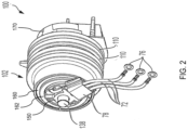
- Fig. 2 depicts a perspective view of outer-rotor brushless DC motor 100in the fastening tool, according to an embodiment.
- Fig. 3 depicts an exploded view of outer-rotor brushless DC motor 100, according to an embodiment.
- Fig. 4 depicts a side cross-sectional view of the motor 100, according to an embodiment.
- motor 100 includes an outer rotor 120 and an inner stator 130.
- outer rotor 120 has a generally cylindrical piped-shaped body with permanent magnets 122 mounted on its inner surface.
- an overmold layer 126 may be provided to secure the magnets 1212 on the inner surface of the outer rotor 120.
- a fan 124 may also be formed via the overmold layer 126, or separately attached to the outer rotor 120 to generate airflow with the rotation of the outer rotor 120.
- outer rotor 120 is provided with a flywheel 102 having three flywheel annular rings 110 that form grooves 112 therebetween around the outer surface of the flywheel 102.
- flywheel 102 is formed integrally with rotor 120 on an external circumferential surface of the rotor 120 having an increased diameter compared to the remainder of the rotor 120.
- flywheel 102 may be provided as a separate part attached to an outer surface of the rotor 120.
- Flywheel 102 may be made of metal such as steel.
- stator 130 includes a stator lamination stack 132 having a plurality of stator teeth projecting from an inner core, with slots formed between the stator teeth. Stator windings 134 are formed of magnet wire wound around the stator teeth to fill in the stator slots, defining the phases of the motor 100. In an embodiment, where motor 100 is a three-phase BLDC motor, three windings 134 defining the three phases of the motor 100 are disposed around the stator lamination stack 132, each winding 134 being wound on opposite two teeth across one another. In an embodiment, stator 130 further includes two end insulators 136 attached to the end surfaces of the stator lamination stack 132.
- the stator lamination stack 132 is mounted (e.g., via press-fitting) on a shaft 138.
- a front bearing 140 may be further mounted on the shaft 138 on one side of the stator 130.
- An outer race of the front bearing 140 is secured to the rotor 120 to provide axial and radial support for the rotor 120 relative to the shaft 138 (and thus relative to the stator 130), while allowing the rotor 120 to rotate freely about the axis of the shaft 138.
- a bearing support structure 162 mounted on the shaft 138 on the other side of the stator 130.
- the bearing support structure 162 includes a center through-hole mounted on the shaft 138.
- the bearing support structure 162 may be securely mounted on the shaft via press-fitting.
- the bearing support structure 162 may be slip fit on the shaft via a wave spring 154, which transmits torque to the rear bearing 160 via the bearing support structure 162.
- the bearing support structure 162 is rotationally fixed relative to the stator 130 and the shaft 138.
- a rear bearing 160 is positioned between the bearing support structure 162 and the rotor 120 to provide further provide axial and radial support for the rotor 120 relative to the shaft 138 (and thus relative to the stator 130), while allowing the rotor 120 to rotate freely about the axis of the shaft 138.
- the rear bearing 160 has a larger diameter than the stator 130, and the inner race of the rear bearing 160 is securely mounted on the outer circumference of the bearing support structure 162, whereas the outer race of the rear bearing 160 is securely mounted inside the inner surface of the rotor 120.
- stator windings 134 are energized in a controlled sequence, they create a magnetic field that interacts with the permanent magnets of the outer rotor 120, thus causing rotation of the outer rotor 120 around the stator 130.
- stator windings 134 are formed of magnet wire wound around stator teeth. In an embodiment, ends of magnet wires, after stator windings 134 are fully wound, are guided out of the stator slots to form the lead wires 72 for electric coupling to the control unit 70. The ends of lead wires 72 may be provided with terminals 76 that facilitate electrical coupling to a connector on the control unit 70.
- a guide member 150 is mounted adjacent a rear end of the bearing support structure 162 to guide the lead wires 72 coming out of the stator 130 in a radial direction away from the motor 100.
- a heat sink 78 is mounted on the guide member 150 to lock the wires 72 in place.
- the guide member 150 is mounted on the shaft 138 via a bushing 152.
- a fan baffle 170 is mounted on the shaft 138 via a bushing 172 adjacent the fan 124.
- the fan baffle 170 includes a circumferential wall 174 formed around the fan 124, with air outlets 176 surrounding fan 124 to allow airflow generated by the fan to be exhausted radially away from the motor.
- a wire trap 180 is further mounted at a distal end of the motor 100 adjacent the fan baffle 170.
- rotating parts of the motor including, but not limited to, the rotor flywheel 102 and other rotor 120 components have been seen to experience some level of wear, causing small metal and/or magnetic particles to separate from the magnets 122 over time and stick to other metal parts of the motor. Build-up of this material in moving components of the motor may increase friction and adversely impact motor performance.
- the rear bearing 160 since a front face of the rear bearing 160 facing the rotor is exposed to the rotor 120, the rear bearing 160 has been particularly prone to build-up of such contamination, causing undesirable slowdown in the motor performance.
- motor 100 is provided with a bearing shield 190 located between the rear bearing 160 and the rotor 120.
- the bearing shield 190 substantially shields the rear bearing 160 from entry of metal particles without interfering with the free and unhindered rotation of the rear bearing 160, as discussed below in detail.
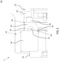
- Fig. 5 depicts a partial cross-sectional view of the motor 100 (i.e., box A in Fig. 4 ) including the bearing shield 190, according to an embodiment.
- Fig. 6 depicts an exploded view of a bearing shield 190, according to an embodiment.
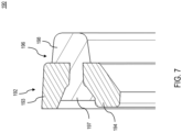
- Fig. 7 depicts a further zoomed-in cross-sectional view of the bearing shield 190, according to an embodiment.
- bearing shield 190 includes a ring-shaped rigid main body 192 that forms two annular portions 193 and 194.
- the main body 192 also includes a series of slots 195 formed therein discussed later.
- the rigid main body 192 may be made of metal or other robust structure such as high-rigidity Nylon material.
- the first annular portion 193 extends in the direction of the rear bearing 160 adjacent an inner surface of the rotor 120 and physically contacts an outer portion (i.e., outer race) of the rear bearing 160.
- the second annular portion 194 is located radially inward of the first annular portion 193 and extends in the direction of an inner portion (i.e., inner race) of the rear bearing 160, but it does not come into contact with the inner portion of the rear bearing 160. Rather, the second annular portion 194 is smaller in axial length than the first annular portion 193 to maintain a small axial gap 199 between the inner portion of the rear bearing 160 and the second annular portion 194 of the bearing shield 190.
- the air gap 199 is sufficiently small in the axial direction (i.e., smaller than approximately 1 mm, preferably smaller than or equal to approximately 0.3 mm, more preferably in the range of 0.1 to 0.2 mm) to ensure that the bearing shield 190 substantially blocks metal particulate and other dust or debris particles from coming into contact with the front face of the rear bearing 160, without making physical contact with the inner race of the bearing to interfere with the rotation of the rotor 120 relative to the rear bearing 160.
- bearing shield 190 further includes a flexible portion 196 made of elastically-deformable material such as Thermoplastic Elastomer (TPE) or other flexible resin material.
- flexible portion 196 includes an anchor portion 197 formed between the two annular portions 193 and 194, and a compression portion 198 formed forward of the main body 192.
- the compression portion 198 axially engages an end of a magnet retaining structure of the rotor 120 (which in this example is the overmold layer 126 that retains the magnets 122 on the inner surface of the rotor 120) to flexibly locate the main body 192 relative to the rotor 120 in the axial direction.
- the flexible portion 196 is formed using an injection-molding process, with molded material passing through the slots 195 of the main body 192 to form the anchor portion 197 and the compression portion 198.
- the bearing shield 190 described herein by way of example provides an efficient and easy to manufacture structure to protect the rear bearing 160 from contamination, particularly by metallic particulate caused due to wear and age of the rotor 120 and/or the flywheel 102. It should be understood that while bearing shield 190 in this example is for use with the rear bearing, the front bearing 140 may be similarly protected. In an embodiment, the bearing shield may be sized appropriately to protect any motor bearing of any size or specification.
- first annular member 193 makes contact with the outer race of the bearing while the second annular member 194 is spaced apart from the inner race
- the inner annular member of the bearing shield may make contact with the inner race of the bearing while the outer annular member of the bearing shield is spaced apart from the outer race.
- bearing shield 190 is described herein as a one-piece component including rigid and flexibly-deformable pieces formed together in an injection-molding process, it should be understood that the rigid and flexibly-deformable pieces may be provided and assembled separately.
- the flexible portion 196 may be an O-ring disposed between a frontal end of the rigid main body 192 and the overmold layer 126.
- first, second, third, etc. may be used herein to describe various elements, components, regions, layers and/or sections, these elements, components, regions, layers and/or sections should not be limited by these terms. These terms may be only used to distinguish one element, component, region, layer or section from another region, layer or section. Terms such as “first,” “second,” and other numerical terms when used herein do not imply a sequence or order unless clearly indicated by the context. Thus, a first element, component, region, layer or section discussed below could be termed a second element, component, region, layer or section without departing from the teachings of the example embodiments.
- spatially relative terms such as “inner,” “outer,” “beneath,” “below,” “lower,” “above,” “upper,” “bottom,” “lower,” and the like, may be used herein for ease of description to describe one element or feature's relationship to another element(s) or feature(s) as illustrated in the figures.
- Spatially relative terms may be intended to encompass different orientations of the device in use or operation in addition to the orientation depicted in the figures. For example, if the device in the figures is turned over, elements described as “below” or “beneath” other elements or features would then be oriented “above” the other elements or features.
- the example term “below” can encompass both an orientation of above and below.
- the device may be otherwise oriented (rotated 90 degrees or at other orientations) and the spatially relative descriptors used herein interpreted accordingly.
- power tool used herein to refer to a rotary device powered by an electric power source and utilized for various applications including, but not limited to, home improvement, construction, automotive repair, outdoor and landscaping maintenance, etc. These include, but are not limited to, angle grinders, die grinders drills, impact drivers, drill drivers, hammers, hammer drills, circular saws, reciprocating saws, miter saws, nailers, polishers, cut-out tools, wrenches, ratchets, sanders, lawn mowers, edgers, trimmers, chain saws, and other lawn maintenance and/or landscaping ride-on equipment.
Landscapes
- Engineering & Computer Science (AREA)
- Power Engineering (AREA)
- General Engineering & Computer Science (AREA)
- Mechanical Engineering (AREA)
- Motor Or Generator Frames (AREA)
Abstract
Description
- This utility patent application claims the benefit of
U.S. Provisional Patent Application No. 63/537,876, filed September 12, 2023 - This disclosure relates to a brushless motor in a power tool, and particularly to a bearing shield for a brushless motor.
- Motors such as brushless DC motors are commonly used in various power tool applications. In tools such as cordless nailers, the brushless motor may be used to generate enough rotary torque to drive a driver that in turns fires a nail into a workpiece. In various examples, described in
US Patent Nos. US9346158 US10766128 US11081933 - The rotor flywheel and other rotor components experience wear with usage over a long period of time, causing metal or magnetic particles to detach from various motor components and build up in areas of the motor that increase friction and adversely impact the motor performance. What is needed is a motor structure that seeks to prevent such built-up of material.
- According to an embodiment of the invention, an electric motor is provided comprising: a stator including a plurality of windings; a center shaft; a rotor arranged outside the stator and supporting at least one permanent magnet in magnetic interface with the plurality of windings; a bearing support structure fixedly mounted on the center shaft adjacent the stator; a bearing located between the bearing support structure and the rotor to rotationally support the rotor relative to the center shaft, the bearing including a first portion and a second portion; and a bearing shield located adjacent the bearing within the rotor, the bearing shield including a first annular portion in contact with the first portion of the bearing, a flexible portion comprising elastically deformable material that biasingly maintains the first annular portion in contact with the first portion of the bearing, and a second annular portion that extends proximate the second portion of the bearing and forms an air gap therebetween, wherein the air gap is sized to allow relative rotation between the second annular portion and the second portion of the bearing but substantially block passage of metal particles therebetween.
- In an embodiment, the bearing support structure is sized such that the bearing is axially aligned with at least one of an outer circumferential surface of the stator or the at least one permanent magnet of the rotor.
- In an embodiment, the first portion of the bearing is an outer race of the bearing coupled to the rotor, and the second portion of the bearing is an inner race of the bearing coupled to the bearing support structure.
- In an embodiment, the second annular portion is radially inward of the first annular portion and the first annular portion is located proximate an inner surface of the rotor.
- In an embodiment, the rotor comprises a magnet retaining structure that supports the at least one permanent magnet, and the flexible portion engages the magnet retaining structure such that the bearing shield is compressed between the rotor and the bearing.
- In an embodiment, the bearing shield comprises a ring-shaped rigid main body that forms the first annular portion.
- In an embodiment, the ring-shaped rigid main body further comprises a plurality of slots, and the flexible portion is insert-molded to the ring-shaped rigid main body via an insert-molded material passing through the plurality of slots.
- In an embodiment, the flexible portion comprises an O-ring compressed between a face of the ring-shaped rigid main body and a part of the motor.
- In an embodiment, the ring-shaped rigid main body is axially aligned with at least one of an outer circumferential surface of the stator or the at least one permanent magnet of the rotor.
- According to an embodiment, a power tool is provided including a housing, and an electric motor disposed within the housing. The electric motor may include the features described above.
- According to an embodiment of the invention, an electric motor is provided comprising: a stator including a plurality of windings; a rotor arranged outside the stator and supporting at least one permanent magnet in magnetic interface with the plurality of windings; a bearing arranged to rotationally support the rotor relative to the stator, the bearing including a first portion and a second portion; and a bearing shield located adjacent the bearing within the rotor, the bearing shield including a first annular portion in contact with the first portion of the bearing, a flexible portion comprising elastically deformable material that biasingly maintains the first annular portion in contact with the first portion of the bearing, and a second annular portion that extends proximate the second portion of the bearing and forms an air gap therebetween, wherein the air gap is sized to allow relative rotation between the second annular portion and the second portion of the bearing but substantially block passage of metal particles therebetween.
- The drawings described herein are for illustration purposes only and are not intended to limit the scope of this disclosure in any way.
-
Fig. 1 depicts a side cross-sectional view of an exemplary fastening power tool, according to an embodiment; -
Fig. 2 depicts a perspective view of an outer-rotor brushless DC motor in the fastening tool, according to an embodiment; -
Fig. 3 depicts an exploded view of the outer-rotor brushless DC motor, according to an embodiment; -
Fig. 4 depicts a side cross-sectional view of the motor, according to an embodiment; -
Fig. 5 depicts a zoomed-in cross-sectional view of the motor including a bearing shield, according to an embodiment; -
Fig. 6 depicts an exploded view of the bearing shield, according to an embodiment; and -
Fig. 7 depicts a further zoomed-in cross-sectional view of the bearing shield, according to an embodiment. - Throughout this specification and figures like reference numbers identify like elements.
- It is to be understood that both the foregoing general description and the following detailed description are exemplary and explanatory only and are intended to provide an explanation of various embodiments of the present teachings.
-
Fig. 1 depicts a perspective view of a fastening tool 10 (e.g., a nailer) with a housing half removed, according to an embodiment. Thefastening tool 10 shown herein includes an outer-rotorbrushless DC motor 100. The outer rotor of themotor 100 is integrally formed with aflywheel 102. In an embodiment, thefastening tool 10 further includes ahousing 12, aninput unit 20 housed within a handle 14 of the housing and coupled to an actuator 22 disposed outside thehousing 12, and acontrol unit 70. - In an embodiment,
control unit 70 includes a microcontroller or other programmable control module and an inverter circuit for controlling a commutation of themotor 100.Control unit 70 is coupled to a power source (not shown), which may be a DC power source (e.g., a removable battery pack) or an AC power source (e.g., a 120V AC).Control unit 70 is also coupled to theinput unit 20 viawires 74 to receive input signals indicative of actions desired by the user. The control module regulates a supply of power from the power source to themotor 100 based on a logic signal from theinput unit 20.Control unit 70 is coupled to motor terminals via threelead wires 72. The inverter circuit may be, for example, a three-phase inverter circuit including three high-side solid-state switches and three low-side solid-state switches. The switching operation of the solid-state switches is controlled by the control module, which regulates supply of electric power from the power supply to themotor 100. - In an embodiment,
fastening tool 10 further includes anosepiece assembly 30 including a contract trip mechanism 32 coupled to thehousing 12, a magazine assembly 40, adriver assembly 50 including adriver 52 and areturn mechanism 52, anactivation assembly 60, and asolenoid 62, among other components. In an embodiment, actuation of the actuator 22 while contact trip mechanism 32 is in contact with a workpiece causes thesolenoid 62 to engage theactivation assembly 62.Activation assembly 62 translates forward and engages thedriver 52 to initiate driving engagement between thedriver 52 and theflywheel 102. In an embodiment, theflywheel 102 includes one or more flywheel rings that form one or more grooves around the outer surface of theflywheel 102. Thedriver 52 includes corresponding railings that engage the grooves of the flywheel. Rotation of theflywheel 102 causes thedriver 52 to accelerate axially and drive a fastener into a workpiece. - The present disclosure is focused on the structure and features of the
motor 100. Details of the components and operation of an exemplary fastening tool are beyond the scope of this disclosure and can be found inU.S. Patent No. 6,971,567 andUS. Patent Publication No. 2012/0097729 , all of which are incorporated herein by reference in their entirety. It is further noted that while themotor 100 of this disclosure is described with reference to a fastening tool according to an exemplary embodiment,motor 100 may similarly be used in other power tools and other rotary devices. -
Fig. 2 depicts a perspective view of outer-rotor brushless DC motor 100in the fastening tool, according to an embodiment.Fig. 3 depicts an exploded view of outer-rotorbrushless DC motor 100, according to an embodiment.Fig. 4 depicts a side cross-sectional view of themotor 100, according to an embodiment. - In an embodiment,
motor 100 includes anouter rotor 120 and aninner stator 130. - In an embodiment,
outer rotor 120 has a generally cylindrical piped-shaped body withpermanent magnets 122 mounted on its inner surface. In an embodiment, anovermold layer 126 may be provided to secure the magnets 1212 on the inner surface of theouter rotor 120. In an embodiment, afan 124 may also be formed via theovermold layer 126, or separately attached to theouter rotor 120 to generate airflow with the rotation of theouter rotor 120. - In an embodiment,
outer rotor 120 is provided with aflywheel 102 having three flywheelannular rings 110 that form grooves 112 therebetween around the outer surface of theflywheel 102. In an embodiment,flywheel 102 is formed integrally withrotor 120 on an external circumferential surface of therotor 120 having an increased diameter compared to the remainder of therotor 120. Alternatively,flywheel 102 may be provided as a separate part attached to an outer surface of therotor 120.Flywheel 102 may be made of metal such as steel. - In an embodiment,
stator 130 includes astator lamination stack 132 having a plurality of stator teeth projecting from an inner core, with slots formed between the stator teeth.Stator windings 134 are formed of magnet wire wound around the stator teeth to fill in the stator slots, defining the phases of themotor 100. In an embodiment, wheremotor 100 is a three-phase BLDC motor, threewindings 134 defining the three phases of themotor 100 are disposed around thestator lamination stack 132, each winding 134 being wound on opposite two teeth across one another. In an embodiment,stator 130 further includes twoend insulators 136 attached to the end surfaces of thestator lamination stack 132. - In an embodiment, the
stator lamination stack 132 is mounted (e.g., via press-fitting) on ashaft 138. Afront bearing 140 may be further mounted on theshaft 138 on one side of thestator 130. An outer race of thefront bearing 140 is secured to therotor 120 to provide axial and radial support for therotor 120 relative to the shaft 138 (and thus relative to the stator 130), while allowing therotor 120 to rotate freely about the axis of theshaft 138. - Further, in an embodiment, a bearing
support structure 162 mounted on theshaft 138 on the other side of thestator 130. The bearingsupport structure 162 includes a center through-hole mounted on theshaft 138. The bearingsupport structure 162 may be securely mounted on the shaft via press-fitting. Alternatively, in an embodiment, the bearingsupport structure 162 may be slip fit on the shaft via awave spring 154, which transmits torque to therear bearing 160 via the bearingsupport structure 162. Thus, the bearingsupport structure 162 is rotationally fixed relative to thestator 130 and theshaft 138. In an embodiment, arear bearing 160 is positioned between the bearingsupport structure 162 and therotor 120 to provide further provide axial and radial support for therotor 120 relative to the shaft 138 (and thus relative to the stator 130), while allowing therotor 120 to rotate freely about the axis of theshaft 138. In an embodiment, therear bearing 160 has a larger diameter than thestator 130, and the inner race of therear bearing 160 is securely mounted on the outer circumference of the bearingsupport structure 162, whereas the outer race of therear bearing 160 is securely mounted inside the inner surface of therotor 120. - In an embodiment, as the
stator windings 134 are energized in a controlled sequence, they create a magnetic field that interacts with the permanent magnets of theouter rotor 120, thus causing rotation of theouter rotor 120 around thestator 130. - In an embodiment, the
stator windings 134 are formed of magnet wire wound around stator teeth. In an embodiment, ends of magnet wires, afterstator windings 134 are fully wound, are guided out of the stator slots to form thelead wires 72 for electric coupling to thecontrol unit 70. The ends oflead wires 72 may be provided withterminals 76 that facilitate electrical coupling to a connector on thecontrol unit 70. In an embodiment, aguide member 150 is mounted adjacent a rear end of the bearingsupport structure 162 to guide thelead wires 72 coming out of thestator 130 in a radial direction away from themotor 100. In an embodiment, aheat sink 78 is mounted on theguide member 150 to lock thewires 72 in place. In an embodiment, theguide member 150 is mounted on theshaft 138 via abushing 152. - In an embodiment, a
fan baffle 170 is mounted on theshaft 138 via abushing 172 adjacent thefan 124. Thefan baffle 170 includes acircumferential wall 174 formed around thefan 124, withair outlets 176 surroundingfan 124 to allow airflow generated by the fan to be exhausted radially away from the motor. In an embodiment, awire trap 180 is further mounted at a distal end of themotor 100 adjacent thefan baffle 170. - With repeated motor use over a long period of time, rotating parts of the motor including, but not limited to, the
rotor flywheel 102 andother rotor 120 components have been seen to experience some level of wear, causing small metal and/or magnetic particles to separate from themagnets 122 over time and stick to other metal parts of the motor. Build-up of this material in moving components of the motor may increase friction and adversely impact motor performance. In some embodiments, since a front face of therear bearing 160 facing the rotor is exposed to therotor 120, therear bearing 160 has been particularly prone to build-up of such contamination, causing undesirable slowdown in the motor performance. - To overcome this problem, according to an embodiment,
motor 100 is provided with abearing shield 190 located between therear bearing 160 and therotor 120. In an embodiment, thebearing shield 190 substantially shields therear bearing 160 from entry of metal particles without interfering with the free and unhindered rotation of therear bearing 160, as discussed below in detail. -
Fig. 5 depicts a partial cross-sectional view of the motor 100 (i.e., box A inFig. 4 ) including thebearing shield 190, according to an embodiment.Fig. 6 depicts an exploded view of abearing shield 190, according to an embodiment.Fig. 7 depicts a further zoomed-in cross-sectional view of thebearing shield 190, according to an embodiment. - In an embodiment, bearing
shield 190 includes a ring-shaped rigidmain body 192 that forms twoannular portions main body 192 also includes a series ofslots 195 formed therein discussed later. In an embodiment, the rigidmain body 192 may be made of metal or other robust structure such as high-rigidity Nylon material. In an embodiment, the firstannular portion 193 extends in the direction of therear bearing 160 adjacent an inner surface of therotor 120 and physically contacts an outer portion (i.e., outer race) of therear bearing 160. In an embodiment, the secondannular portion 194 is located radially inward of the firstannular portion 193 and extends in the direction of an inner portion (i.e., inner race) of therear bearing 160, but it does not come into contact with the inner portion of therear bearing 160. Rather, the secondannular portion 194 is smaller in axial length than the firstannular portion 193 to maintain a smallaxial gap 199 between the inner portion of therear bearing 160 and the secondannular portion 194 of thebearing shield 190. Theair gap 199 is sufficiently small in the axial direction (i.e., smaller than approximately 1 mm, preferably smaller than or equal to approximately 0.3 mm, more preferably in the range of 0.1 to 0.2 mm) to ensure that thebearing shield 190 substantially blocks metal particulate and other dust or debris particles from coming into contact with the front face of therear bearing 160, without making physical contact with the inner race of the bearing to interfere with the rotation of therotor 120 relative to therear bearing 160. - In an embodiment, bearing
shield 190 further includes aflexible portion 196 made of elastically-deformable material such as Thermoplastic Elastomer (TPE) or other flexible resin material. In an embodiment,flexible portion 196 includes ananchor portion 197 formed between the twoannular portions compression portion 198 formed forward of themain body 192. Thecompression portion 198 axially engages an end of a magnet retaining structure of the rotor 120 (which in this example is theovermold layer 126 that retains themagnets 122 on the inner surface of the rotor 120) to flexibly locate themain body 192 relative to therotor 120 in the axial direction. This arrangement ensures that thebearing shield 190 is axially restrained and securely compressed between therear bearing 160 and therotor 120 and does not separate from therear bearing 160. In an embodiment, theflexible portion 196 is formed using an injection-molding process, with molded material passing through theslots 195 of themain body 192 to form theanchor portion 197 and thecompression portion 198. - The
bearing shield 190 described herein by way of example provides an efficient and easy to manufacture structure to protect therear bearing 160 from contamination, particularly by metallic particulate caused due to wear and age of therotor 120 and/or theflywheel 102. It should be understood that while bearingshield 190 in this example is for use with the rear bearing, thefront bearing 140 may be similarly protected. In an embodiment, the bearing shield may be sized appropriately to protect any motor bearing of any size or specification. Further, while in this embodiment, the firstannular member 193 makes contact with the outer race of the bearing while the secondannular member 194 is spaced apart from the inner race, it is envisioned that for some bearings, the inner annular member of the bearing shield may make contact with the inner race of the bearing while the outer annular member of the bearing shield is spaced apart from the outer race. - While the
bearing shield 190 is described herein as a one-piece component including rigid and flexibly-deformable pieces formed together in an injection-molding process, it should be understood that the rigid and flexibly-deformable pieces may be provided and assembled separately. In an example, theflexible portion 196 may be an O-ring disposed between a frontal end of the rigidmain body 192 and theovermold layer 126. - The foregoing description of the embodiments has been provided for purposes of illustration and description. It is not intended to be exhaustive or to limit the disclosure. Individual elements or features of a particular embodiment are generally not limited to that particular embodiment, but, where applicable, are interchangeable and can be used in a selected embodiment, even if not specifically shown or described. The same may also be varied in many ways. Such variations are not to be regarded as a departure from the disclosure, and all such modifications are intended to be included within the scope of the disclosure.
- The terminology used herein is for the purpose of describing particular example embodiments only and is not intended to be limiting. As used herein, the singular forms "a," "an," and "the" may be intended to include the plural forms as well, unless the context clearly indicates otherwise. The terms "comprises," "comprising," "including," and "having," are inclusive and therefore specify the presence of stated features, integers, steps, operations, elements, and/or components, but do not preclude the presence or addition of one or more other features, integers, steps, operations, elements, components, and/or groups thereof. The method steps, processes, and operations described herein are not to be construed as necessarily requiring their performance in the particular order discussed or illustrated, unless specifically identified as an order of performance. It is also to be understood that additional or alternative steps may be employed.
- When an element or layer is referred to as being "on," "engaged to," "connected to," or "coupled to" another element or layer, it may be directly on, engaged, connected or coupled to the other element or layer, or intervening elements or layers may be present. In contrast, when an element is referred to as being "directly on," "directly engaged to," "directly connected to," or "directly coupled to" another element or layer, there may be no intervening elements or layers present. Other words used to describe the relationship between elements should be interpreted in a like fashion (e.g., "between" versus "directly between," "adjacent" versus "directly adjacent," etc.). As used herein, the term "and/or" includes any and all combinations of one or more of the associated listed items.
- Although the terms first, second, third, etc. may be used herein to describe various elements, components, regions, layers and/or sections, these elements, components, regions, layers and/or sections should not be limited by these terms. These terms may be only used to distinguish one element, component, region, layer or section from another region, layer or section. Terms such as "first," "second," and other numerical terms when used herein do not imply a sequence or order unless clearly indicated by the context. Thus, a first element, component, region, layer or section discussed below could be termed a second element, component, region, layer or section without departing from the teachings of the example embodiments.
- Spatially relative terms, such as "inner," "outer," "beneath," "below," "lower," "above," "upper," "bottom," "lower," and the like, may be used herein for ease of description to describe one element or feature's relationship to another element(s) or feature(s) as illustrated in the figures. Spatially relative terms may be intended to encompass different orientations of the device in use or operation in addition to the orientation depicted in the figures. For example, if the device in the figures is turned over, elements described as "below" or "beneath" other elements or features would then be oriented "above" the other elements or features. Thus, the example term "below" can encompass both an orientation of above and below. The device may be otherwise oriented (rotated 90 degrees or at other orientations) and the spatially relative descriptors used herein interpreted accordingly.
- The term "power tool" used herein to refer to a rotary device powered by an electric power source and utilized for various applications including, but not limited to, home improvement, construction, automotive repair, outdoor and landscaping maintenance, etc. These include, but are not limited to, angle grinders, die grinders drills, impact drivers, drill drivers, hammers, hammer drills, circular saws, reciprocating saws, miter saws, nailers, polishers, cut-out tools, wrenches, ratchets, sanders, lawn mowers, edgers, trimmers, chain saws, and other lawn maintenance and/or landscaping ride-on equipment.
Claims (10)
- An electric motor comprising:a stator including a plurality of windings;a center shaft;a rotor arranged outside the stator and supporting at least one permanent magnet in magnetic interface with the plurality of windings;a bearing support structure fixedly mounted on the center shaft adjacent the stator;a bearing located between the bearing support structure and the rotor to rotationally support the rotor relative to the center shaft, the bearing including a first portion and a second portion; anda bearing shield located adjacent the bearing within the rotor, the bearing shield including a first annular portion in contact with the first portion of the bearing, a flexible portion comprising elastically deformable material that biasingly maintains the first annular portion in contact with the first portion of the bearing, and a second annular portion that extends proximate the second portion of the bearing and forms an air gap therebetween, wherein the air gap is sized to allow relative rotation between the second annular portion and the second portion of the bearing but substantially block passage of metal particles therebetween.
- The electric motor of claim 1, wherein the bearing support structure is sized such that the bearing is axially aligned with at least one of an outer circumferential surface of the stator or the at least one permanent magnet of the rotor.
- The electric motor of claim 1 or 2, wherein the first portion of the bearing is an outer race of the bearing coupled to the rotor, and the second portion of the bearing is an inner race of the bearing coupled to the bearing support structure.
- The electric motor of claim 3, wherein the second annular portion is radially inward of the first annular portion and the first annular portion is located proximate an inner surface of the rotor.
- The electric motor of any preceding claim, wherein the rotor comprises a magnet retaining structure that supports the at least one permanent magnet, and the flexible portion engages the magnet retaining structure such that the bearing shield is compressed between the rotor and the bearing.
- The electric motor of any preceding claim, wherein the bearing shield comprises a ring-shaped rigid main body that forms the first annular portion.
- The electric motor of claim 6, wherein the ring-shaped rigid main body further comprises a plurality of slots, wherein the flexible portion is insert-molded to the ring-shaped rigid main body via an insert-molded material passing through the plurality of slots.
- The electric motor of claim 6 or 7, wherein the flexible portion comprises an O-ring compressed between a face of the ring-shaped rigid main body and a part of the motor.
- The electric motor of any of claims 6 to 8, wherein the ring-shaped rigid main body is axially aligned with at least one of an outer circumferential surface of the stator or the at least one permanent magnet of the rotor.
- A power tool comprising:a housing; andthe electric motor according to any of the preceding claims, wherein the electric motor is disposed within the housing for driving an output.
Applications Claiming Priority (2)
| Application Number | Priority Date | Filing Date | Title |
|---|---|---|---|
| US202363537876P | 2023-09-12 | 2023-09-12 | |
| US18/817,422 US20250088072A1 (en) | 2023-09-12 | 2024-08-28 | Motor bearing shield |
Publications (2)
| Publication Number | Publication Date |
|---|---|
| EP4525277A1 true EP4525277A1 (en) | 2025-03-19 |
| EP4525277B1 EP4525277B1 (en) | 2026-04-08 |
Family
ID=92632914
Family Applications (1)
| Application Number | Title | Priority Date | Filing Date |
|---|---|---|---|
| EP24197669.5A Active EP4525277B1 (en) | 2023-09-12 | 2024-08-30 | Motor bearing shield |
Country Status (2)
| Country | Link |
|---|---|
| US (1) | US20250088072A1 (en) |
| EP (1) | EP4525277B1 (en) |
Citations (7)
| Publication number | Priority date | Publication date | Assignee | Title |
|---|---|---|---|---|
| US6971567B1 (en) | 2004-10-29 | 2005-12-06 | Black & Decker Inc. | Electronic control of a cordless fastening tool |
| US20120097729A1 (en) | 2004-04-02 | 2012-04-26 | Black & Decker Inc. | Power take off for cordless nailer |
| US9346158B2 (en) | 2012-09-20 | 2016-05-24 | Black & Decker Inc. | Magnetic profile lifter |
| US20190032787A1 (en) * | 2016-01-26 | 2019-01-31 | Flender Gmbh | Seal |
| US20200217367A1 (en) * | 2019-01-09 | 2020-07-09 | Nidec Corporation | Motor, blowing device, and vacuum cleaner |
| US10766128B2 (en) | 2014-07-28 | 2020-09-08 | Black & Decker Inc. | Power tool drive mechanism |
| US11081933B2 (en) | 2014-12-18 | 2021-08-03 | Black & Decker Inc. | Brushless motor assembly for a fastening tool |
-
2024
- 2024-08-28 US US18/817,422 patent/US20250088072A1/en active Pending
- 2024-08-30 EP EP24197669.5A patent/EP4525277B1/en active Active
Patent Citations (7)
| Publication number | Priority date | Publication date | Assignee | Title |
|---|---|---|---|---|
| US20120097729A1 (en) | 2004-04-02 | 2012-04-26 | Black & Decker Inc. | Power take off for cordless nailer |
| US6971567B1 (en) | 2004-10-29 | 2005-12-06 | Black & Decker Inc. | Electronic control of a cordless fastening tool |
| US9346158B2 (en) | 2012-09-20 | 2016-05-24 | Black & Decker Inc. | Magnetic profile lifter |
| US10766128B2 (en) | 2014-07-28 | 2020-09-08 | Black & Decker Inc. | Power tool drive mechanism |
| US11081933B2 (en) | 2014-12-18 | 2021-08-03 | Black & Decker Inc. | Brushless motor assembly for a fastening tool |
| US20190032787A1 (en) * | 2016-01-26 | 2019-01-31 | Flender Gmbh | Seal |
| US20200217367A1 (en) * | 2019-01-09 | 2020-07-09 | Nidec Corporation | Motor, blowing device, and vacuum cleaner |
Also Published As
| Publication number | Publication date |
|---|---|
| US20250088072A1 (en) | 2025-03-13 |
| EP4525277B1 (en) | 2026-04-08 |
Similar Documents
| Publication | Publication Date | Title |
|---|---|---|
| US11646626B2 (en) | Brushless motor for a power tool | |
| US20220166283A1 (en) | Brushless motor for a power tool | |
| US11411467B2 (en) | Electric motor for a power tool | |
| US11670977B2 (en) | Outer rotor brushless motor stator mount | |
| US11784518B2 (en) | Electric motor for a power tool | |
| EP3654497B1 (en) | Winding retention insert for a brushless motor | |
| EP3035508A2 (en) | Brushless motor assembly for a fastening tool | |
| US20060087193A1 (en) | Power tool | |
| EP4525277B1 (en) | Motor bearing shield | |
| EP4079457B1 (en) | Transmission assembly to battery connection in power tool | |
| US12027919B2 (en) | Rotor magnet retainer | |
| EP4461473A1 (en) | Wire guide and retention unit for power tool | |
| US20240339885A1 (en) | Wire guide and retention unit for power tool | |
| EP4550640A1 (en) | Electric tool including an outer-rotor motor | |
| JP2026037779A (en) | electric work equipment | |
| JP2026008889A (en) | Electric work machine and manufacturing method thereof |
Legal Events
| Date | Code | Title | Description |
|---|---|---|---|
| PUAI | Public reference made under article 153(3) epc to a published international application that has entered the european phase |
Free format text: ORIGINAL CODE: 0009012 |
|
| STAA | Information on the status of an ep patent application or granted ep patent |
Free format text: STATUS: THE APPLICATION HAS BEEN PUBLISHED |
|
| AK | Designated contracting states |
Kind code of ref document: A1 Designated state(s): AL AT BE BG CH CY CZ DE DK EE ES FI FR GB GR HR HU IE IS IT LI LT LU LV MC ME MK MT NL NO PL PT RO RS SE SI SK SM TR |
|
| STAA | Information on the status of an ep patent application or granted ep patent |
Free format text: STATUS: REQUEST FOR EXAMINATION WAS MADE |
|
| 17P | Request for examination filed |
Effective date: 20250919 |
|
| GRAP | Despatch of communication of intention to grant a patent |
Free format text: ORIGINAL CODE: EPIDOSNIGR1 |
|
| STAA | Information on the status of an ep patent application or granted ep patent |
Free format text: STATUS: GRANT OF PATENT IS INTENDED |
|
| INTG | Intention to grant announced |
Effective date: 20251104 |
|
| RAP3 | Party data changed (applicant data changed or rights of an application transferred) |
Owner name: BLACK & DECKER INC. |
|
| RIC1 | Information provided on ipc code assigned before grant |
Ipc: H02K 5/10 20060101AFI20251024BHEP Ipc: H02K 7/08 20060101ALI20251024BHEP Ipc: H02K 5/173 20060101ALI20251024BHEP Ipc: F16C 33/78 20060101ALI20251024BHEP Ipc: H02K 7/14 20060101ALN20251024BHEP |
|
| GRAS | Grant fee paid |
Free format text: ORIGINAL CODE: EPIDOSNIGR3 |
|
| GRAA | (expected) grant |
Free format text: ORIGINAL CODE: 0009210 |
|
| STAA | Information on the status of an ep patent application or granted ep patent |
Free format text: STATUS: THE PATENT HAS BEEN GRANTED |
|
| AK | Designated contracting states |
Kind code of ref document: B1 Designated state(s): AL AT BE BG CH CY CZ DE DK EE ES FI FR GB GR HR HU IE IS IT LI LT LU LV MC ME MK MT NL NO PL PT RO RS SE SI SK SM TR |
|
| REG | Reference to a national code |
Ref country code: CH Ref legal event code: F10 Free format text: ST27 STATUS EVENT CODE: U-0-0-F10-F00 (AS PROVIDED BY THE NATIONAL OFFICE) Effective date: 20260408 Ref country code: GB Ref legal event code: FG4D |
|
| P01 | Opt-out of the competence of the unified patent court (upc) registered |
Free format text: CASE NUMBER: UPC_APP_0009280_4525277/2026 Effective date: 20260310 |
|
| REG | Reference to a national code |
Ref country code: DE Ref legal event code: R096 Ref document number: 602024003810 Country of ref document: DE |