EP4525274A1 - Rotor einer elektrischen maschine - Google Patents
Rotor einer elektrischen maschine Download PDFInfo
- Publication number
- EP4525274A1 EP4525274A1 EP24191803.6A EP24191803A EP4525274A1 EP 4525274 A1 EP4525274 A1 EP 4525274A1 EP 24191803 A EP24191803 A EP 24191803A EP 4525274 A1 EP4525274 A1 EP 4525274A1
- Authority
- EP
- European Patent Office
- Prior art keywords
- rotor
- disc
- plastic disc
- cooling
- rotor body
- Prior art date
- Legal status (The legal status is an assumption and is not a legal conclusion. Google has not performed a legal analysis and makes no representation as to the accuracy of the status listed.)
- Pending
Links
Images

Classifications
-
- H—ELECTRICITY
- H02—GENERATION; CONVERSION OR DISTRIBUTION OF ELECTRIC POWER
- H02K—DYNAMO-ELECTRIC MACHINES
- H02K1/00—Details of the magnetic circuit
- H02K1/06—Details of the magnetic circuit characterised by the shape, form or construction
- H02K1/22—Rotating parts of the magnetic circuit
- H02K1/32—Rotating parts of the magnetic circuit with channels or ducts for flow of cooling medium
-
- H—ELECTRICITY
- H02—GENERATION; CONVERSION OR DISTRIBUTION OF ELECTRIC POWER
- H02K—DYNAMO-ELECTRIC MACHINES
- H02K7/00—Arrangements for handling mechanical energy structurally associated with dynamo-electric machines, e.g. structural association with mechanical driving motors or auxiliary dynamo-electric machines
- H02K7/04—Balancing means
-
- H—ELECTRICITY
- H02—GENERATION; CONVERSION OR DISTRIBUTION OF ELECTRIC POWER
- H02K—DYNAMO-ELECTRIC MACHINES
- H02K9/00—Arrangements for cooling or ventilating
- H02K9/19—Arrangements for cooling or ventilating for machines with closed casing and closed-circuit cooling using a liquid cooling medium, e.g. oil
-
- H—ELECTRICITY
- H02—GENERATION; CONVERSION OR DISTRIBUTION OF ELECTRIC POWER
- H02K—DYNAMO-ELECTRIC MACHINES
- H02K1/00—Details of the magnetic circuit
- H02K1/06—Details of the magnetic circuit characterised by the shape, form or construction
- H02K1/22—Rotating parts of the magnetic circuit
- H02K1/27—Rotor cores with permanent magnets
- H02K1/2706—Inner rotors
- H02K1/272—Inner rotors the magnetisation axis of the magnets being perpendicular to the rotor axis
- H02K1/274—Inner rotors the magnetisation axis of the magnets being perpendicular to the rotor axis the rotor consisting of two or more circumferentially positioned magnets
- H02K1/2753—Inner rotors the magnetisation axis of the magnets being perpendicular to the rotor axis the rotor consisting of two or more circumferentially positioned magnets the rotor consisting of magnets or groups of magnets arranged with alternating polarity
- H02K1/276—Magnets embedded in the magnetic core, e.g. interior permanent magnets [IPM]
-
- H—ELECTRICITY
- H02—GENERATION; CONVERSION OR DISTRIBUTION OF ELECTRIC POWER
- H02K—DYNAMO-ELECTRIC MACHINES
- H02K15/00—Processes or apparatus specially adapted for manufacturing, assembling, maintaining or repairing of dynamo-electric machines
- H02K15/12—Impregnating, moulding insulation, heating or drying of windings, stators, rotors or machines
Definitions
- the invention is based on a rotor of an electrical machine according to the preamble of the main claim.
- the rotor of an electrical machine according to the invention with the characterizing features of the main claim has the advantage that the end plate arrangement is simpler and more cost-effective to manufacture.
- This is achieved according to the invention in that a plastic disc is firmly molded onto an uppermost cover plate of the rotor body, in that several connecting channels are formed on the plastic disc, each as an inlet into one of the cooling channels or as an outlet from one of the cooling channels, and in that the connecting channels of the plastic disc are covered, in particular completely, by the balancing disc.
- the plastic disc is injection-moulded or cast onto the cover lamella by means of injection moulding or transfer moulding (injection moulding).
- the rotor body has magnetic pockets for accommodating magnets, in particular permanent magnets.
- the magnetic pockets are filled with a cured molding compound to secure the magnets, which extends outside the magnetic pockets to form at least one plastic disc. This allows the plastic disc to be co-produced from the molding compound during the filling of the magnetic pockets.
- the molding compound is thus used to produce the plastic disc. This reduces the manufacturing costs of the rotor. Furthermore, the seal between the respective cooling channel of the rotor body and the associated connecting channel of the plastic disc is improved.
- the connecting channels of the plastic disc are open toward the balancing disc, in particular, they are designed as a through-hole or through-recess. This allows the connecting channels to be easily formed in the plastic disc using tool slides.
- the open connecting channels are at least largely covered by the balancing disc to close or seal the connecting channels.
- the plastic disc has a circumferentially closed annular section radially outside the cooling channels, on which an annular sealing surface and/or at least one annular or partially annular shoulder is formed for receiving the balancing disc. This ensures a good seal of the connecting channels in the end disc arrangement.
- the respective connecting channel can flow-connect the cooling channel with the shaft cooling channel and form an inlet connection into the cooling channel. In this way, the respective cooling channel is supplied with cooling fluid from the rotor shaft.
- the respective connecting channel can form an outlet connection from the cooling channel. In this way, an outlet from the respective cooling channel is created. The outlet connection can lead back into the shaft cooling channel or into an adjacent cooling channel, or form an outlet for spraying the cooling fluid.
- each cooling channel has an inlet connection at one end and an outlet connection at its other end, wherein the inlets into the cooling channels are formed in only one of the two plastic discs according to a second embodiment or in both plastic discs according to a first embodiment.
- the same flow direction is set in the cooling channels of all rotor poles in the second embodiment, and an opposite flow direction is set in the cooling channels of adjacent rotor poles in the first embodiment.
- a plastic disc is provided on each of the two cover lamellae of the rotor body.
- inlets into the cooling channels in the rotor body are formed between the two cover lamellae of the rotor body, in particular in the center of a stack, and the connecting channels of both plastic discs are each designed as outlet connections. In this way, two flow directions running in opposite directions are established in each cooling channel, each starting from the inlet into the respective cooling channel.
- the rotor body is enclosed by a rotor sleeve, in particular by a fiber composite sleeve wound directly onto the rotor with prestress, and the respective plastic disc extends in the radial direction to the circumference of the rotor body, with a winding start or a winding end of the rotor sleeve lying on the plastic disc.
- the invention further relates to an electrical machine with a rotor according to the invention.
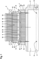
- Fig.1 shows an electrical machine with a rotor having two end plate arrangements according to the invention.
- the rotor 1 of an electric machine 2 has a rotor shaft 4 rotatable about a rotor axis 3, a rotor body 5, in particular a rotor core, mechanically coupled to the rotor shaft 4, and at least one end plate arrangement 8 arranged on one of the two end faces of the rotor body 5.
- the end plate arrangement 8 comprises a balancing disc 9, which is, for example, a metal disc. Cooling channels 6 are formed in the rotor body 5, extending in the axial direction with respect to the rotor axis 3 and fluidly connected to a shaft cooling channel 7 of the rotor shaft 4 for the purpose of supplying cooling fluid.
- a plastic disc 10 which is part of the end disc arrangement 8, is firmly formed on an uppermost cover plate 12 of the rotor body 5.
- several connecting channels 13 are formed on the plastic disc 10, each of which is designed as an inlet into one of the cooling channels 6 or as an outlet from one of the cooling channels 6.
- connecting channels 13 of the plastic disc 10 are at least partially covered, in particular completely covered, by the balancing disc 9.
- the plastic disc 10 can be injection-molded or cast onto the cover lamella 12, for example by means of injection molding or transfer molding.
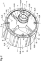
- Fig.2 shows the rotor Fig.1 with a side view of a plastic disc according to the invention of one of the two end disc assemblies according to a first embodiment.
- the balancing disc of the end disc assembly is in Fig.2 not shown.
- Fig.3 shows the rotor Fig.1 with a side view of a plastic disc according to the invention of one of the two end disc assemblies according to a second embodiment.
- the balancing disc of the end disc assembly is shown in Fig.3 not shown.
- the rotor body 5 can have magnetic pockets 14 for accommodating magnets 15, in particular permanent magnets.
- the magnetic pockets 14 can be filled with a cured molding compound 16 that extends outside the magnetic pockets 14 to form at least one plastic disc 10.
- the cooling channels 6 can be formed in the molding compound 16 of the magnetic pockets 14 and/or directly in the rotor core 5.
- each rotor pole 18 has a V-shaped magnetic layer with at least one magnetic pocket 14.
- each rotor pole 18 has two V-shaped magnetic layers, each with at least one magnetic pocket 14.
- the connecting channels 13 of the plastic disc 10 are open towards the balancing disc 9, in particular as a through-opening or through-recess.
- the connecting channels are formed, for example, by a star-shaped radially inner edge contour 17 of the plastic disc 10.
- the plastic disc 10 can comprise, radially outside the cooling channels 6, a circumferentially closed annular section 20 on which an annular sealing surface 21 and/or at least one annular or partially annular shoulder 22 is provided for receiving the balancing disc 9.
- a support surface 23 for the balancing disc 9 to rest on is provided radially inside the shoulder 22.
- the respective connecting channel 13 can fluidly connect the cooling channel 6 with the shaft cooling channel 7 via a shaft opening 11 in the rotor shaft 4 and form an inlet connection 25 into the cooling channel 6.
- the respective connecting channel 13 can represent an outlet connection 26 from the cooling channel 6.
- the outlet connection 26 can lead back into the shaft cooling channel 7 or into an adjacent cooling channel 6 or form an outlet for spraying the cooling fluid.
- the outlet for spraying the cooling fluid can be arranged from the cooling channel 6 according to Fig.2 with respect to the rotor axis 3 in the plastic disc 10 radially outwards or according to an alternative cooling path 28 in Fig.1 run radially inwards in the plastic disc 10 and then be guided through a through opening in the balancing disc 9.
- FIG.1 A plastic disc 10 is provided on each of the two cover lamellas 12 of the rotor body 5.
- each cooling channel 6 has an inlet connection 25 at one end and an outlet connection 26 at the other end.
- Fig.1 cooling path 27 shown with arrows.
- the inlets into the cooling channels 6 can only be arranged in one of the two ( Fig.3 ) or according to the first embodiment in both plastic discs 10 ( Fig.2 ) must be trained.
- the inlets into the cooling channels 6 in the rotor body 5 can be provided, viewed in the axial direction, between the two cover lamellae 12 of the rotor body 5, in particular in the center of the stack, wherein the connecting channels 13 of both plastic discs 10 are each designed as an outlet connection 25.
- two flow directions running in opposite directions are set in each cooling channel 6, each starting from the inlet into the respective cooling channel 6.
- the flow directions running in opposite directions in the respective cooling channel 6 according to the third exemplary embodiment result in an alternative cooling path 28 shown by dashed arrows.
- the cooling path 28 leads via an outlet connection 26 in the plastic disc 10 and a through-opening in the balancing disc 9 to the outside of the rotor 1.
- the output connection 26 according to the alternative cooling path 28 is, in contrast to the cooling path 27, not fluidly connected to the shaft cooling channel 7.
- the rotor body 5 can be enclosed by a rotor sleeve 30, in particular by a fiber composite sleeve wound with prestress directly onto the rotor 1.
- the respective plastic disc 10 can extend in the radial direction up to the circumference of the rotor body 5, so that a winding start and/or a winding end of the rotor sleeve 30 can be positioned on the circumference of the plastic disc 10.
Landscapes
- Engineering & Computer Science (AREA)
- Power Engineering (AREA)
- Motor Or Generator Cooling System (AREA)
Abstract
Description
- Die Erfindung geht aus von einem Rotor einer elektrischen Maschine nach der Gattung des Hauptanspruchs.
- Es ist schon ein Rotor einer elektrischen Maschine aus der
DE102019133532 A1 bekannt, mit einem auf der Rotorwelle angeordneten Rotorkörper, insbesondere einem Rotorblechpaket, und mit zumindest einer an einer der beiden Stirnseiten des Rotorkörpers angeordneten metallischen Wuchtscheibe, wobei im Rotorkörper in axialer Richtung bezüglich der Rotorachse verlaufende Kühlkanäle ausgebildet sind, die zur Kühlfluidversorgung mit einem Wellenkühlkanal der Rotorwelle strömungsverbunden sind. In der metallischen Wuchtscheibe sind Verbindungskanäle zur Fluidversorgung des Kühlpfads des Rotors vorgesehen. Die metallische Wuchtscheibe ist durch die Integration der Verbindungskanäle aufwendig herzustellen. - Der erfindungsgemäße Rotor einer elektrischen Maschine mit den kennzeichnenden Merkmalen des Hauptanspruchs hat demgegenüber den Vorteil, dass die Endscheibenanordnung einfacher und kostengünstiger herstellbar ist. Dies wird erfindungsgemäß erreicht, indem an eine oberste Decklamelle des Rotorkörpers eine Kunststoffscheibe fest angeformt ist, indem an der Kunststoffscheibe mehrere Verbindungskanäle jeweils als Einlass in einen der Kühlkanäle oder als Auslass aus einem der Kühlkanäle ausgebildet sind und indem die Verbindungskanäle der Kunststoffscheibe durch die Wuchtscheibe überdeckt sind, insbesondere vollständig. Durch das feste Anformen der Kunststoffscheibe an die oberste Decklamelle des Rotorkörpers, beispielsweise durch Spritzgussgießen oder Transfermolden, wird außerdem eine gute Abdichtung zwischen der Kunststoffscheibe und dem Rotorkörper erreicht, so dass zwischen der Kunststoffscheibe und dem Rotorkörper keine oder nur eine geringe Leckage von Kühlfluid aus den Kühlkanälen des Rotors auftritt.
- Durch die in den Unteransprüchen aufgeführten Maßnahmen sind vorteilhafte Weiterbildungen und Verbesserungen des im Hauptanspruch angegebenen Rotors einer elektrischen Maschine möglich.
- Gemäß einer vorteilhaften Ausführung ist die Kunststoffscheibe mittels Spritzgussgießen oder mittels Transfermolden (Spritzpressen) an die Decklamelle angespritzt oder angegossen ist.
- Sehr vorteilhaft ist es, wenn der Rotorkörper Magnettaschen zur Aufnahme von Magneten, insbesondere Permanentmagneten, aufweist, wobei die Magnettaschen zur Fixierung der Magnete mit einer ausgehärteten Moldmasse ausgefüllt sind, die sich nach außerhalb der Magnettaschen erstreckt unter Bildung zumindest einer Kunststoffscheibe. Dadurch kann die Kunststoffscheibe im Zuge des Ausfüllens der Magnettaschen aus der Moldmasse miterzeugt werden. Die Moldmasse wird also zur Erzeugung der Kunststoffscheibe genutzt. Auf diese Weise werden die Herstellungskosten des Rotors verringert. Außerdem wird die Abdichtung zwischen dem jeweiligen Kühlkanal des Rotorkörpers und dem zugeordenten Verbindungskanal der Kunststoffscheibe verbessert.
- Besonders vorteilhaft ist, wenn die Verbindungskanäle der Kunststoffscheibe zur Wuchtscheibe hin offen ausgeführt, insbesondere als Durchgangsöffnung oder Durchgangsausnehmung ausgebildet, sind. Dadurch können die Verbindungskanäle auf einfache Weise mittels von Werkzeugschiebern in der Kunststoffscheibe ausgeformt werden. Die offen ausgeführten Verbindungskanäle werden zum Verschließen oder Abdichten der Verbindungskanäle durch die Wuchtscheibe zumindest überwiegend abgedeckt.
- Weiterhin vorteilhaft ist, wenn die Kunststoffscheibe radial außerhalb der Kühlkanäle einen in Umfangsrichtung geschlossenen Ringabschnitt aufweist, an dem eine ringförmige Dichtfläche und/oder zumindest eine ring- oder teilringförmige Schulter zum Aufnehmen der Wuchtscheibe ausgebildet ist. Auf diese Weise wird in der Endscheibenanordnung eine gute Abdichtung der Verbindungskanäle erreicht.
- Nach einer vorteilhaften ersten Art von Kanalverbindung kann der jeweilige Verbindungskanal den Kühlkanal mit dem Wellenkühlkanal strömungsverbinden und eine Eingangsverbindung in den Kühlkanal bilden. Auf diese Weise wird der jeweilige Kühlkanal mit Kühlfluid aus der Rotorwelle versorgt. Alternativ kann der jeweilige Verbindungskanal nach einer vorteilhaften zweiten Art von Kanalverbindung eine Ausgangsverbindung aus dem Kühlkanal bilden. Auf diese Weise wird ein Auslass aus dem jeweiligen Kühlkanal hergestellt. Die Ausgangsverbindung kann zurück in den Wellenkühlkanal oder in einen benachbarten Kühlkanal führen oder einen Auslass zum Versprühen des Kühlfluids bilden.
- Darüber hinaus vorteilhaft ist, wenn an beiden Decklamellen des Rotorkörpers jeweils eine Kunststoffscheibe ausgeführt ist, wobei nach einer ersten Strömungsführungs-Variante jeder Kühlkanal an seinen einen Ende eine Eingangsverbindung und an seinem anderen Ende eine Ausgangsverbindung aufweist, wobei die Einlässe in die Kühlkanäle nach einem zweiten Ausführungsbeispiel nur in einer der beiden Kunststoffscheiben oder nach einem ersten Ausführungsbeispiel in beiden Kunststoffscheiben ausgebildet sind. Auf diese Weise wird beim zweiten Ausführungsbeispiel in den Kühlkanälen aller Rotorpole die gleiche Strömungsrichtung und beim ersten Ausführungsbeispiel eine entgegengesetzte Strömungsrichtung in den Kühlkanälen von benachbarten Rotorpolen eingestellt.
- Desweiteren vorteilhaft ist, wenn an beiden Decklamellen des Rotorkörpers jeweils eine Kunststoffscheibe ausgeführt ist, wobei nach einem dritten Ausführungsbeispiel Einlässe in die Kühlkanäle im Rotorkörper zwischen den zwei Decklamellen des Rotorkörpers ausgebildet sind, insbesondere in einer Paketmitte, und wobei die Verbindungskanäle beider Kunststoffscheiben jeweils als Ausgangsverbindung ausgeführt sind. Auf diese Weise werden in jedem Kühlkanal, jeweils ausgehend vom Einlass in den jeweiligen Kühlkanal, zwei in entgegengesetzter Richtung verlaufende Strömungsrichtungen eingestellt.
- Vorteilhaft ist, wenn der Rotorkörper von einer Rotorhülse, insbesondere von einer mit Vorspannung direkt auf den Rotor gewickelten Faserverbundhülse, umschlossen ist und die jeweilige Kunststoffscheibe in radialer Richtung bis an den Umfang des Rotorkörpers reicht, wobei ein Wickelanfang oder ein Wickelende der Rotorhülse auf der Kunststoffscheibe liegt.
- Die Erfindung betrifft weiterhin eine elektrische Maschine mit einem erfindungsgemäßen Rotor.
- Drei Ausführungsbeispiele der Erfindung sind in der Zeichnung vereinfacht dargestellt und in der nachfolgenden Beschreibung näher erläutert.
- Es zeigen:
- Fig.1
- im Schnitt eine elektrische Maschine mit einem Rotor, der zwei erfindungsgemäße Endscheibenanordnungen aufweist,
- Fig.2
- den Rotor nach
Fig.1 mit einer Seitenansicht auf eine erfindungsgemäße Kunststoffscheibe einer der beiden Endscheibenanordnungen gemäß einem ersten Ausführungsbeispiel und - Fig.3
- den Rotor nach
Fig.1 mit einer Seitenansicht auf eine erfindungsgemäße Kunststoffscheibe einer der beiden Endscheibenanordnungen gemäß einem zweiten Ausführungsbeispiel. -
Fig.1 zeigt eine elektrische Maschine mit einem Rotor, der zwei erfindungsgemäße Endscheibenanordnungen aufweist. - Der erfindungsgemäße Rotor 1 einer elektrischen Maschine 2 weist eine um eine Rotorachse 3 drehbare Rotorwelle 4, einen mit der Rotorwelle 4 mechanisch gekoppelten Rotorkörper 5, insbesondere ein Rotorblechpaket, und zumindest eine an einer der beiden Stirnseiten des Rotorkörpers 5 angeordnete Endscheibenanordnung 8 auf. Die Endscheibenanordnung 8 umfasst eine Wuchtscheibe 9, die beispielsweise eine Metallscheibe ist. Im Rotorkörper 5 sind in axialer Richtung bezüglich der Rotorachse 3 verlaufende Kühlkanäle 6 ausgebildet, die zur Kühlfluidversorgung mit einem Wellenkühlkanal 7 der Rotorwelle 4 strömungsverbunden sind.
- Erfindungsgemäß ist vorgesehen, dass an eine oberste Decklamelle 12 des Rotorkörpers 5 eine Kunststoffscheibe 10 fest angeformt ist, die Teil der Endscheibenanordnung 8 ist. An der Kunststoffscheibe 10 sind erfindungsgemäß mehrere Verbindungskanäle 13 ausgebildet, die jeweils als Einlass in einen der Kühlkanäle 6 oder als Auslass aus einem der Kühlkanäle 6 ausgeführt sind. Die Verbindungskanäle 13 der Kunststoffscheibe 10 sind erfindungsgemäß durch die Wuchtscheibe 9 zumindest teilweise überdeckt, insbesondere vollständig überdeckt.
- Die Kunststoffscheibe 10 kann beispielsweise mittels Spritzgussgießen oder mittels Transfermolden an die Decklamelle 12 angespritzt oder angegossen sein.
-
Fig.2 zeigt den Rotor nachFig.1 mit einer Seitenansicht auf eine erfindungsgemäße Kunststoffscheibe einer der beiden Endscheibenanordnungen gemäß einem ersten Ausführungsbeispiel. Die Wuchtscheibe der Endscheibenanordnung ist inFig.2 nicht dargestellt. -
Fig.3 zeigt den Rotor nachFig.1 mit einer Seitenansicht auf eine erfindungsgemäße Kunststoffscheibe einer der beiden Endscheibenanordnungen gemäß einem zweiten Ausführungsbeispiel. Die Wuchtscheibe der Endscheibenanordnung ist inFig.3 nicht dargestellt. - Der Rotorkörper 5 kann Magnettaschen 14 zur Aufnahme von Magneten 15, insbesondere Permanentmagneten, aufweisen. Die Magnettaschen 14 können zur Fixierung der Magnete 15 mit einer ausgehärteten Moldmasse 16 ausgefüllt sein, die sich nach außerhalb der Magnettaschen 14 erstreckt unter Bildung zumindest einer Kunststoffscheibe 10. Die Kühlkanäle 6 können in der Moldmasse 16 der Magnettaschen 14 und/oder unmittelbar im Rotorblechpaket 5 ausgebildet sein.
- Der Rotor 1 nach
Fig.2 hat pro Rotorpol 18 beispielsweise eine V-förmige Magnetlage mit zumindest einer Magnettasche 14. - Der Rotor 1 nach
Fig.3 hat pro Rotorpol 18 beispielsweise zwei V-förmige Magnetlagen mit jeweils zumindest einer Magnettasche 14. - Die Verbindungskanäle 13 der Kunststoffscheibe 10 sind zur Wuchtscheibe 9 hin offen ausgeführt, insbesondere als Durchgangsöffnung oder Durchgangsausnehmung ausgebildet. Nach
Fig.2 undFig.3 sind die Verbindungskanäle beispielsweise durch eine sternförmige radial innere Randkontur 17 der Kunststoffscheibe 10 gebildet. - Die Kunststoffscheibe 10 kann radial außerhalb der Kühlkanäle 6 einen in Umfangsrichtung geschlossenen Ringabschnitt 20 umfassen, an dem eine ringförmige Dichtfläche 21 und/oder zumindest eine ring- oder teilringförmige Schulter 22 zum Aufnehmen der Wuchtscheibe 9 vorgesehen ist. Im Falle der Ausbildung einer Schulter 22 ist radial innerhalb der Schulter 22 eine Auflagefläche 23 zum Aufliegen der Wuchtscheibe 9 ausgeführt.
- Der jeweilige Verbindungskanal 13 kann den Kühlkanal 6 mit dem Wellenkühlkanal 7 über eine Wellenöffnung 11 in der Rotorwelle 4 strömungsverbinden und eine Eingangsverbindung 25 in den Kühlkanal 6 bilden. Alternativ kann der jeweilige Verbindungskanal 13 eine Ausgangsverbindung 26 aus dem Kühlkanal 6 darstellen. Die Ausgangsverbindung 26 kann zurück in den Wellenkühlkanal 7 oder in einen benachbarten Kühlkanal 6 führen oder einen Auslass zum Versprühen des Kühlfluids bilden. Der Auslass zum Versprühen des Kühlfluids kann vom Kühlkanal 6 ausgehend gemäß
Fig.2 bezüglich der Rotorachse 3 in der Kunststoffscheibe 10 nach radial außen oder gemäß einem alternativen Kühlpfad 28 inFig.1 in der Kunststoffscheibe 10 nach radial innen verlaufen und dann durch eine Durchgangsöffnung in der Wuchtscheibe 9 geführt sein. - Nach
Fig.1 ist an beiden Decklamellen 12 des Rotorkörpers 5 jeweils eine Kunststoffscheibe 10 ausgeführt. - Nach dem ersten und zweiten Ausführungsbeispiel weist jeder Kühlkanal 6 an seinen einen Ende eine Eingangsverbindung 25 und an seinem anderen Ende eine Ausgangsverbindung 26 auf. Dabei stellt sich beispielsweise der in
Fig.1 mit Pfeilen dargestellte Kühlpfad 27 ein. - Die Einlässe in die Kühlkanäle 6 können nach dem zweiten Ausführungsbeispiel nur in einer der beiden (
Fig.3 ) oder nach dem ersten Ausführungsbeispiel in beiden Kunststoffscheiben 10 (Fig.2 ) ausgebildet sein. - Nach einem dritten Ausführungsbeispiel können die Einlässe in die Kühlkanäle 6 im Rotorkörper 5 in axialer Richtung gesehen zwischen den zwei Decklamellen 12 des Rotorkörpers 5 vorgesehen sein, insbesondere in einer Paketmitte, wobei die Verbindungskanäle 13 beider Kunststoffscheiben 10 jeweils als Ausgangsverbindung 25 ausgeführt sind. Dadurch werden in jedem Kühlkanal 6, jeweils ausgehend vom Einlass in den jeweiligen Kühlkanal 6, zwei in entgegengesetzter Richtung verlaufende Strömungsrichtungen eingestellt. Die im jeweiligen Kühlkanal 6 in entgegengesetzter Richtung verlaufenden Strömungsrichtungen gemäß dem dritten Ausführungsbeispiel ergeben einen mit gestrichelten Pfeilen dargestellten alternativen Kühlpfad 28. Der Kühlpfad 28 führt über eine Ausgangsverbindung 26 in der Kunststoffscheibe 10 und eine Durchgangsöffnung in der Wuchtscheibe 9 nach außerhalb des Rotors 1. Die Ausgangsverbindung 26 gemäß dem alternativen Kühlpfad 28 ist im Gegensatz zum Kühlpfad 27 nicht mit dem Wellenkühlkanal 7 strömungsverbunden.
- Nach
Fig.1 kann der Rotorkörper 5 von einer Rotorhülse 30, insbesondere von einer mit Vorspannung direkt auf den Rotor 1 gewickelten Faserverbundhülse, umschlossen sein. Die jeweilige Kunststoffscheibe 10 kann in radialer Richtung bis an den Umfang des Rotorkörpers 5 reichen, so dass ein Wickelanfang und/oder ein Wickelende der Rotorhülse 30 am Umfang der Kunststoffscheibe 10 positioniert sein kann.
Claims (10)
- Rotor einer elektrischen Maschine (2) mit einer um eine Rotorachse (3) drehbaren Rotorwelle (4), mit einem auf der Rotorwelle (4) angeordneten Rotorkörper (5), insbesondere einem Rotorblechpaket, und mit zumindest einer an einer der beiden Stirnseiten des Rotorkörpers (5) angeordneten Endscheibenanordnung (8), die eine Wuchtscheibe (9) umfasst, wobei im Rotorkörper (5) in axialer Richtung bezüglich der Rotorachse (3) verlaufende Kühlkanäle (6) ausgebildet sind, die zur Kühlfluidversorgung mit einem Wellenkühlkanal (7) der Rotorwelle (4) strömungsverbunden sind,
dadurch gekennzeichnet, dass- an eine oberste Decklamelle (12) des Rotorkörpers (5) eine Kunststoffscheibe (10) fest angeformt ist, die Teil der Endscheibenanordnung (8) ist,- an der Kunststoffscheibe (10) mehrere Verbindungskanäle (13) jeweils als Einlass in einen der Kühlkanäle (6) oder als Auslass aus einem der Kühlkanäle (6) ausgebildet sind und dass- die Verbindungskanäle (13) der Kunststoffscheibe (10) durch die Wuchtscheibe (9) überdeckt sind, insbesondere vollständig. - Rotor nach Anspruch 1, dadurch gekennzeichnet, dass die Kunststoffscheibe (10) mittels Spritzgussgießen oder mittels Transfermolden an die Decklamelle (12) angespritzt oder angegossen ist.
- Rotor nach einem der vorhergehenden Ansprüche, dadurch gekennzeichnet, dass der Rotorkörper (5) Magnettaschen (14) zur Aufnahme von Magneten (15), insbesondere Permanentmagneten, aufweist, wobei die Magnettaschen (14) zur Fixierung der Magnete (15) mit einer ausgehärteten Moldmasse (16) ausgefüllt sind, die sich nach außerhalb der Magnettaschen (14) erstreckt unter Bildung zumindest einer Kunststoffscheibe (10).
- Rotor nach einem der vorhergehenden Ansprüche, dadurch gekennzeichnet, dass die Verbindungskanäle (13) der Kunststoffscheibe (10) zur Wuchtscheibe (9) hin offen ausgeführt, insbesondere als Durchgangsöffnung oder Durchgangsausnehmung ausgebildet, sind.
- Rotor nach einem der vorhergehenden Ansprüche, dadurch gekennzeichnet, dass die Kunststoffscheibe (10) radial außerhalb der Kühlkanäle (6) einen in Umfangsrichtung geschlossenen Ringabschnitt (20) umfasst, an dem eine ringförmige Dichtfläche (21) und/oder zumindest eine ring- oder teilringförmige Schulter (22) zum Aufnehmen der Wuchtscheibe (9) ausgebildet ist.
- Rotor nach einem der vorhergehenden Ansprüche, dadurch gekennzeichnet, dassa. der jeweilige Verbindungskanal (13) den Kühlkanal (6) mit dem Wellenkühlkanal (7) strömungsverbindet und eine Eingangsverbindung (25) in den Kühlkanal (6) bildet, oderb. der jeweilige Verbindungskanal (13) eine Ausgangsverbindung (26) aus dem Kühlkanal (6) bildet.
- Rotor nach Anspruch 6, dadurch gekennzeichnet, dass an beiden Decklamellen (12) des Rotorkörpers (5) jeweils eine Kunststoffscheibe (10) ausgeführt ist, wobei jeder Kühlkanal (6) an seinen einen Ende eine Eingangsverbindung (25) und an seinem anderen Ende eine Ausgangsverbindung (26) aufweist, wobei Einlässe in die Kühlkanäle (6) in einer der beiden oder in beiden Kunststoffscheiben (10) ausgebildet sind.
- Rotor nach Anspruch 6, dadurch gekennzeichnet, dass an beiden Decklamellen (12) des Rotorkörpers (5) jeweils eine Kunststoffscheibe (10) ausgeführt ist, wobei Einlässe in die Kühlkanäle (6) im Rotorkörper (5) zwischen den zwei Decklamellen (12) des Rotorkörpers (5) ausgebildet sind, insbesondere in einer Paketmitte, und wobei die Verbindungskanäle (13) beider Kunststoffscheiben (10) jeweils als Ausgangsverbindung (26) ausgeführt sind.
- Rotor nach einem der vorhergehenden Ansprüche, dadurch gekennzeichnet, dass der Rotorkörper von einer Rotorhülse(30), insbesondere von einer mit Vorspannung direkt auf den Rotor (1) gewickelten Faserverbundhülse, umschlossen ist und die jeweilige Kunststoffscheibe (10) in radialer Richtung bis an den Umfang des Rotorkörpers (5) reicht, wobei ein Wickelanfang oder ein Wickelende der Rotorhülse (30) auf der Kunststoffscheibe (10) liegt.
- Elektrische Maschine (2) mit einem Rotor (1) nach einem der vorhergehenden Ansprüche.
Applications Claiming Priority (1)
| Application Number | Priority Date | Filing Date | Title |
|---|---|---|---|
| DE102023209016.3A DE102023209016A1 (de) | 2023-09-18 | 2023-09-18 | Rotor einer elektrischen Maschine |
Publications (1)
| Publication Number | Publication Date |
|---|---|
| EP4525274A1 true EP4525274A1 (de) | 2025-03-19 |
Family
ID=92208596
Family Applications (1)
| Application Number | Title | Priority Date | Filing Date |
|---|---|---|---|
| EP24191803.6A Pending EP4525274A1 (de) | 2023-09-18 | 2024-07-30 | Rotor einer elektrischen maschine |
Country Status (2)
| Country | Link |
|---|---|
| EP (1) | EP4525274A1 (de) |
| DE (1) | DE102023209016A1 (de) |
Citations (7)
| Publication number | Priority date | Publication date | Assignee | Title |
|---|---|---|---|---|
| WO2013136405A1 (ja) * | 2012-03-12 | 2013-09-19 | トヨタ自動車株式会社 | 回転電機 |
| KR20180037757A (ko) * | 2016-10-05 | 2018-04-13 | 현대모비스 주식회사 | 모터 회전자 및 그 제조벙법 |
| US20190190358A1 (en) * | 2017-12-20 | 2019-06-20 | Abb Schweiz Ag | Rotor Balancing/Fixation Via Injection or Compression Molding |
| DE102018111993A1 (de) * | 2018-05-18 | 2019-11-21 | Dr. Ing. H.C. F. Porsche Aktiengesellschaft | Rotor mit einer Endscheibenanordnung |
| DE102019133532A1 (de) | 2019-12-09 | 2021-06-10 | Dr. Ing. H.C. F. Porsche Aktiengesellschaft | Rotor für eine elektrische Maschine, elektrische Maschine, Kraftfahrzeug |
| DE102020215450A1 (de) * | 2020-12-08 | 2022-06-09 | Robert Bosch Gesellschaft mit beschränkter Haftung | Rotor einer elektrischen Maschine |
| CN115173602A (zh) * | 2022-07-28 | 2022-10-11 | 小米汽车科技有限公司 | 转子组件、电机和车辆 |
-
2023
- 2023-09-18 DE DE102023209016.3A patent/DE102023209016A1/de active Pending
-
2024
- 2024-07-30 EP EP24191803.6A patent/EP4525274A1/de active Pending
Patent Citations (7)
| Publication number | Priority date | Publication date | Assignee | Title |
|---|---|---|---|---|
| WO2013136405A1 (ja) * | 2012-03-12 | 2013-09-19 | トヨタ自動車株式会社 | 回転電機 |
| KR20180037757A (ko) * | 2016-10-05 | 2018-04-13 | 현대모비스 주식회사 | 모터 회전자 및 그 제조벙법 |
| US20190190358A1 (en) * | 2017-12-20 | 2019-06-20 | Abb Schweiz Ag | Rotor Balancing/Fixation Via Injection or Compression Molding |
| DE102018111993A1 (de) * | 2018-05-18 | 2019-11-21 | Dr. Ing. H.C. F. Porsche Aktiengesellschaft | Rotor mit einer Endscheibenanordnung |
| DE102019133532A1 (de) | 2019-12-09 | 2021-06-10 | Dr. Ing. H.C. F. Porsche Aktiengesellschaft | Rotor für eine elektrische Maschine, elektrische Maschine, Kraftfahrzeug |
| DE102020215450A1 (de) * | 2020-12-08 | 2022-06-09 | Robert Bosch Gesellschaft mit beschränkter Haftung | Rotor einer elektrischen Maschine |
| CN115173602A (zh) * | 2022-07-28 | 2022-10-11 | 小米汽车科技有限公司 | 转子组件、电机和车辆 |
Also Published As
| Publication number | Publication date |
|---|---|
| DE102023209016A1 (de) | 2025-03-20 |
Similar Documents
| Publication | Publication Date | Title |
|---|---|---|
| EP3669439B1 (de) | Rotor für eine elektrische maschine, insbesondere eines kraftfahrzeugs, sowie verfahren zum herstellen eines solchen rotors | |
| DE102021113691A1 (de) | Stator einer elektrischen Antriebsmaschine und Verfahren zum Herstellen desselben | |
| DE102020215450A1 (de) | Rotor einer elektrischen Maschine | |
| DE102007041099A1 (de) | Rotoranordnung für eine elektrische Maschine | |
| DE102023206887A1 (de) | Rotor einer elektrischen Maschine | |
| WO2023099124A1 (de) | Elektrische maschine, insbesondere elektrischer antriebsmotor für kraftfahrzeuge, mit einem rotor | |
| DE4115273C1 (de) | ||
| DE102020117266A1 (de) | Statoranordnung für eine Elektromaschine | |
| DE102017206091B3 (de) | Elektrischer Antriebsmotor, Nassläufer-Pumpe und Haushaltsgerät, sowie Verfahren zur Herstellung eines solchen elektrischen Antriebsmotors | |
| DE102013110101A1 (de) | Drehende elektrische Maschine | |
| DE102017210742B4 (de) | Verfahren zum Herstellen eines Rotors für eine elektrische Maschine, insbesondere eines Kraftfahrzeugs | |
| EP3364529B1 (de) | Stator für einen elektromotor | |
| WO2024033054A1 (de) | Rotor einer elektrischen maschine | |
| DE102019117832B4 (de) | Stator für eine elektrische Maschine und elektrische Maschine | |
| EP4525274A1 (de) | Rotor einer elektrischen maschine | |
| EP3391509B1 (de) | Elektromotor | |
| DE102019118646A1 (de) | Spritzgegossener Magnethalter für einen bürstenlosen Elektromotor | |
| DE102013201320B4 (de) | Verfahren zum Herstellen eines Stators und Stator | |
| DE102022211538A1 (de) | Rotor einer elektrischen Maschine | |
| DE102023203074A1 (de) | Elektrisches Funktionsteil mit einer Hochvoltschnittstelle | |
| DE102018127501A1 (de) | EC-Motor für ein elektrisches Handwerkzeug sowie Verfahren zur Herstellung eines Rotors für einen EC-Motor | |
| DE112021002313T5 (de) | Stator | |
| WO2023232654A1 (de) | Rotorvorrichtung, elektrische maschine, temperierfluidumlenkeinheit, verfahren zur herstellung eines rotorblechpakets und verwendung eines verbindungsmittels | |
| DE102021109730A1 (de) | Elektrischer Kraftfahrzeug-Traktionsmotor | |
| DE102024203075A1 (de) | Rotor einer elektrischen Maschine |
Legal Events
| Date | Code | Title | Description |
|---|---|---|---|
| PUAI | Public reference made under article 153(3) epc to a published international application that has entered the european phase |
Free format text: ORIGINAL CODE: 0009012 |
|
| STAA | Information on the status of an ep patent application or granted ep patent |
Free format text: STATUS: THE APPLICATION HAS BEEN PUBLISHED |
|
| AK | Designated contracting states |
Kind code of ref document: A1 Designated state(s): AL AT BE BG CH CY CZ DE DK EE ES FI FR GB GR HR HU IE IS IT LI LT LU LV MC ME MK MT NL NO PL PT RO RS SE SI SK SM TR |
|
| STAA | Information on the status of an ep patent application or granted ep patent |
Free format text: STATUS: REQUEST FOR EXAMINATION WAS MADE |
|
| 17P | Request for examination filed |
Effective date: 20250919 |
|
| STAA | Information on the status of an ep patent application or granted ep patent |
Free format text: STATUS: EXAMINATION IS IN PROGRESS |
|
| 17Q | First examination report despatched |
Effective date: 20260218 |