EP4525266A1 - Switchless uninterrupted power supply - Google Patents
Switchless uninterrupted power supply Download PDFInfo
- Publication number
- EP4525266A1 EP4525266A1 EP24175085.0A EP24175085A EP4525266A1 EP 4525266 A1 EP4525266 A1 EP 4525266A1 EP 24175085 A EP24175085 A EP 24175085A EP 4525266 A1 EP4525266 A1 EP 4525266A1
- Authority
- EP
- European Patent Office
- Prior art keywords
- copper bar
- assembly
- cabinet
- pass
- output
- Prior art date
- Legal status (The legal status is an assumption and is not a legal conclusion. Google has not performed a legal analysis and makes no representation as to the accuracy of the status listed.)
- Pending
Links
Images




Classifications
-
- H—ELECTRICITY
- H02—GENERATION; CONVERSION OR DISTRIBUTION OF ELECTRIC POWER
- H02J—ELECTRIC POWER NETWORKS; CIRCUIT ARRANGEMENTS OR SYSTEMS FOR SUPPLYING OR DISTRIBUTING ELECTRIC POWER; SYSTEMS FOR STORING ELECTRIC ENERGY
- H02J9/00—Circuit arrangements for emergency or stand-by power supply, e.g. for emergency lighting
Definitions
- the present disclosure relates to the field of uninterrupted power supplies, and in particular to a switchless uninterrupted power supply.
- a technical problem to be solved in the present disclosure is to provide a switchless uninterrupted power supply in a flexible configuration.
- the switchless uninterrupted power supply can be conveniently and quickly configured for various application scenarios according to on-site customer demands.
- a switchless uninterrupted power supply includes a cabinet, and a wiring assembly, a monitor module, a by-pass module, and a power module arranged in the cabinet.
- the wiring assembly, the monitor module, the by-pass module and the power module are arranged vertically.
- a power wire opening is formed on a top of the cabinet.
- the wiring assembly is arranged at the power wire opening.
- the wiring assembly includes a main copper bar assembly, a by-pass copper bar assembly, an output copper bar assembly and a ground copper bar.
- the by-pass copper bar assembly is arranged at a front half portion in a depth direction of the cabinet.
- the main copper bar assembly, the output copper bar assembly and the ground copper bar are arranged at a back half portion in the depth direction of the cabinet.
- main copper bar assembly and the output copper bar assembly are arranged oppositely in a width direction of the cabinet.
- ground copper bar is arranged behind the main copper bar assembly and the output copper bar assembly in the depth direction of the cabinet.
- the wiring assembly includes a battery wiring assembly.
- the battery wiring assembly and the by-pass copper bar assembly are arranged in parallel in the width direction of the cabinet, and are arranged at the front half portion of the cabinet.
- the battery wiring assembly and the main copper bar assembly are arranged in parallel along the depth direction of the cabinet.
- the battery wiring assembly includes an anode wiring copper bar and a cathode wiring copper bar.
- Each of the anode wiring copper bar and the cathode wiring copper bar includes two parts connected together. First parts of the anode wiring copper bar and the cathode wiring copper bar extend along the depth direction of the cabinet. Second parts of the anode wiring copper bar and the cathode wiring copper bar extend from the top of the cabinet to a bottom of the cabinet.
- the wiring assembly includes a neutral wire copper bar.
- the neutral wire copper bar and the output copper bar assembly are arranged in parallel along the depth direction of the cabinet.
- the neutral wire copper bar extends along a height direction of the cabinet.
- each of the main copper bar assembly and the output copper bar assembly includes two parts connected together. First parts of the main copper bar assembly and the output copper bar assembly extend along the width direction of the cabinet. Second parts of the main copper bar assembly and the output copper bar assembly extend from the top of the cabinet to the bottom of the cabinet.
- an input terminal of the by-pass module is connected to the by-pass copper bar assembly arranged on a top of the by-pass module.
- An output terminal of the by-pass module is connected to the second part of the output copper bar assembly arranged at a rear portion of a side of behind the by-pass module.
- the main copper bar assembly includes a first main copper bar, a second main copper bar and a third main copper bar.
- the first main copper bar, the second main copper bar and the third main copper bar are arranged in parallel along the depth direction of the cabinet.
- the output copper bar assembly includes a first output copper bar, a second output copper bar and a third output copper bar.
- the first output copper bar, the second output copper bar and the third output copper bar are arranged in parallel along the depth direction of the cabinet.
- the by-pass copper bar assembly includes a first by-pass copper bar, a second by-pass copper bar and a third by-pass copper bar.
- the first by-pass copper bar, the second by-pass copper bar and the third by-pass copper bar are arranged in parallel along the width direction of the cabinet.
- the switchless uninterrupted power supply has a compact layout and a great power density, and is adaptable to various power distribution scenarios.
- the wiring assembly is directly connected in use, and time spent on assembly is reduced greatly.
- Reference symbols include: 100 cabinet, 110 power wire opening, 120 control wire opening, 130 internal cover plate and viewing window, 140 incoming wire strip board, 150 slide rail, 200 monitor module, 300 by-pass module, 400 power module, 500 wiring assembly, m main copper bar assembly mA first main copper bar, mB second main copper bar, mC third main copper bar, b by-pass copper bar assembly, bA first by-pass copper bar, bB second by-pass copper bar, bC third by-pass copper bar, o output copper bar assembly, oA first output copper bar, oB second output copper bar, oC third output copper bar, N neutral wire copper bar, PE ground copper bar, 520 battery wiring assembly, 521 anode wiring copper bar, 522 cathode wiring copper bar.
- an element when described as being “fixed” or “arranged” on another element, may be arranged on the other element directly or indirectly.
- An element, when described as being “connected” to another element may be connected to the other element directly or indirectly.
- orientations or positional relationships indicated by the terms such as “length”, “width” “upper”, “lower”, “front”, “back”, “left”, “right”, “vertical”, “horizontal”, “top”, “bottom”, “inner”, “outer” and the like are based on the orientations or positional relationships shown in the drawings. These terms are only used to facilitate the description of the present disclosure and to simplify the description, rather than indicate or imply that a device or element referred to must have a specific orientation or be arranged and operated in a specific orientation. Therefore, these terms should not be construed as a limitation to the present disclosure.
- first and second are merely used for purpose of description, and should not be construed as indicating or implying relative importance or implying the number of the indicated technical features. Therefore, a feature defined by “first” and “second” may explicitly or implicitly be one or more in number. In the description of the present disclosure, “multiple” indicates two or more, unless specifically defined otherwise.
- the switchless uninterrupted power supply includes a cabinet 100, and a wiring assembly 500, a monitor module 200, a by-pass module 300, and a power module 400 arranged in the cabinet 100.
- the wiring assembly 500, the monitor module 200, the by-pass module 300 and the power module 400 are arranged vertically.
- a power wire opening 110 is formed on the top of the cabinet 100.
- the wiring assembly 500 is arranged at the power wire opening 110.
- Such a arrangement has a compact layout, provides a great power density, and is adaptable to various power distribution scenarios.
- the wiring assembly 500 is directly connected in use, and time spent on assembly is reduced greatly.
- the cabinet 100 is roughly a rectangular box as a whole.
- the monitor module 200, the by-pass module 300, the power module 400, the wiring assembly 500 and the like are arranged inside the cabinet 100.
- the wiring assembly 500, the monitor module 200, the by-pass module 300 and the power module 400 are arranged along a height direction of the cabinet 100.
- Multiple slide rails 150 are arranged on a side wall of the cabinet 100 near the front of the cabinet 100.
- the monitor module 200, the by-pass module 300 and the power module 400 are mounted on the slide rails 150 in a pullable manner.
- the multiple power modules 400 are stacked along the height direction of the cabinet 100.
- the number of the power module 400 is not limited in the present disclosure, and the number of the power module 400 may be increased or decreased, depending on actual situations.
- the power wire opening 110 is formed at the top of the cabinet 100.
- a detachable incoming wire strip board 140 is arranged at the power wire opening 110.
- the wiring assembly 500 is arranged below the incoming wire strip board 140.
- the wiring assembly 500 is exposed after the incoming wire strip board 140 is detached, thereby facilitating wiring.
- An internal cover plate and viewing window 130 and a control wire opening 120 are arranged at an upper part of a front face of the cabinet 100.
- the internal cover plate and viewing window 130 and the control wire opening 120 are arranged corresponding to a height of the wiring assembly 500.
- the internal cover plate and viewing window 130 and the control wire opening 120 are arranged along the depth direction of the cabinet 100 with the wiring assembly 500.
- the wiring assembly 500 includes a main copper bar assembly m, a by-pass copper bar assembly b, an output copper bar assembly o, a neutral wire bar N, a ground copper bar PE, and a battery wiring assembly 520.
- the by-pass copper bar assembly b and the battery wiring assembly 520 are arranged at a front half portion in the depth direction of the cabinet 100.
- the main copper bar assembly m, the output copper bar assembly o, the neutral wire copper bar N and the ground copper bar PE are arranged at a back half portion in the depth direction of the cabinet 100.
- the main copper bar assembly m and the output copper bar assembly o are arranged oppositely in a width direction of the cabinet 100.
- Each of the main copper bar assembly m and the output copper bar assembly o has a shape of "7" as a whole, and includes two parts connected together. First parts of the main copper bar assembly m and the output copper bar assembly o extend along the width direction of the cabinet 100. Second parts of the main copper bar assembly m and the output copper bar assembly o extend from the top of the cabinet 100 to the bottom of the cabinet 100.
- the main copper bar assembly m includes a first main copper bar mA, a second main copper bar mB and a third main copper bar mC.
- the first main copper bar mA, the second main copper bar mB and the third main copper bar mC are arranged in parallel along the depth direction of the cabinet 100.
- each of the first main copper bar mA, the second main copper bar mB and the third main copper bar mC has a shape of "7", and includes two parts connected together.
- first parts of the first main copper bar mA, the second main copper bar mB and the third main copper bar mC extend along the width direction of the cabinet 100, and second parts of the first main copper bar mA, the second main copper bar mB and the third main copper bar mC extend from the top of the cabinet 100 to the bottom of the cabinet 100.
- the output copper bar assembly o includes a first output copper bar oA, a second output copper bar oB and a third output copper bar oC.
- the first output copper bar oA, the second output copper bar oB and the third output copper bar oC are arranged in parallel along the depth direction of the cabinet 100.
- each of the first output copper bar oA, the second output copper bar oB and the third output copper bar oC has a shape of "7", and includes two parts connected together.
- first parts of the first output copper bar oA, the second output copper bar oB and the third output copper bar oC extend along the width direction of the cabinet 100, and second parts of the first output copper bar oA, the second output copper bar oB and the third output copper bar oC extend from the top of the cabinet 100 to the bottom of the cabinet 100.
- the neutral wire copper bar N and the output copper bar assembly o are arranged in parallel along the depth direction of the cabinet 100.
- the neutral wire copper bar N extends along the height direction of the cabinet 100. That is, the neutral wire copper bar N is arranged in parallel with the second parts of the first output copperbar oA, the second output copper bar oB and the third output copper bar oC. Furthermore, the neutral wire copper bar N is closer to the by-pass copper bar assembly b than the second parts of the first output copper bar oA, the second output copper bar oB and the third output copper bar oC.
- the by-pass copper bar assembly b includes a first by-pass copper bar bA, a second by-pass copper bar bB and a third by-pass copper bar bC.
- the first by-pass copper bar bA, the second by-pass copper bar bB and the third by-pass copper bar bC are arranged in parallel along the width direction of the cabinet 100.
- Each of the first by-pass copper bar bA, the second by-pass copper bar bB and the third by-pass copper bar bC has a shape of "-", and extends along the depth direction of the cabinet 100.
- the ground copper bar PE is arranged behind the main copper bar assembly m and the output copper bar assembly o in the depth direction of the cabinet 100, and extends along the width direction of the cabinet 100.
- the battery wiring assembly 520 and the by-pass copper bar assembly b are arranged in parallel in the width direction of the cabinet 100, and are arranged at a front half portion of the cabinet 100.
- the battery wiring assembly 520 and the main copper bar assembly m are arranged in parallel along the depth direction of the cabinet 100.
- the battery wiring assembly 520 includes an anode wiring copper bar 521 and a cathode wiring copper bar 522.
- the anode wiring copper bar 521 and the cathode wiring copper bar 522 each includes two parts connected together. First parts of the anode wiring copper bar 521 and the cathode wiring copper bar 522 extend along the depth direction of the cabinet 100. Second parts of the anode wiring copper bar 521 and the cathode wiring copper bar 522 extend from the top of the cabinet 100 to the bottom of the cabinet 100.
- an input terminal of the by-pass module 300 is connected to the by-pass copper bar assembly b arranged on the top of the by-pass module 300.
- An output terminal of the by-pass module 300 is connected to the second part of the output copper bar assembly o arranged at a rear portion of a side of the by-pass module 300.
- the input and output terminals of the by-pass module 300 each adopts full copper bar carriers, thereby decreasing cost and increasing efficiency of the device.
- All the modules and the wiring assembly 500 in the switchless uninterrupted power supply have a proper layout, which is convenient and secure for wiring.
- the layout of the main copper bar assembly m, the output copper bar assembly o, the by-pass copper bar assembly b, the neutral wire copper bar N, the ground copper bar PE and the battery wiring assembly 520 improves the reliability of the system and the current sharing of the device.
Landscapes
- Business, Economics & Management (AREA)
- Emergency Management (AREA)
- Engineering & Computer Science (AREA)
- Power Engineering (AREA)
- Distribution Board (AREA)
- Stand-By Power Supply Arrangements (AREA)
Abstract
The present disclosure discloses a switchless uninterrupted power supply, which includes a cabinet, a wiring assembly, a monitor module, a by-pass module, and a power module. The wiring assembly, the monitor module, the by-pass module and the power module are arranged vertically in the cabinet. A power wire opening is formed on a top of the cabinet. The wiring assembly is arranged at the power wire opening. The switchless uninterrupted power supply has a compact layout and great power density, and is adaptable to various power distribution scenarios. The wiring assembly is directly connected in use, and time spent on assembly is reduced greatly.
Description
- The present disclosure relates to the field of uninterrupted power supplies, and in particular to a switchless uninterrupted power supply.
- Specific customers are demanding an uninterrupted power supply (UPS) with a particular layout in the market, to adapt to the requirements of various power systems. With the development of technology, a power density of the uninterrupted power supply is increasing, and requirement for reliability of products is higher. Therefore, it is necessary to provide a switchless uninterrupted power supply to increase the reliability of products maximally through an innovative layout while meeting the requirement for a great power density.
- A technical problem to be solved in the present disclosure is to provide a switchless uninterrupted power supply in a flexible configuration. The switchless uninterrupted power supply can be conveniently and quickly configured for various application scenarios according to on-site customer demands.
- To solve the technical problem above, the following technical solutions are provided in the present disclosure.
- A switchless uninterrupted power supply includes a cabinet, and a wiring assembly, a monitor module, a by-pass module, and a power module arranged in the cabinet. The wiring assembly, the monitor module, the by-pass module and the power module are arranged vertically. A power wire opening is formed on a top of the cabinet. The wiring assembly is arranged at the power wire opening.
- Further, the wiring assembly includes a main copper bar assembly, a by-pass copper bar assembly, an output copper bar assembly and a ground copper bar. The by-pass copper bar assembly is arranged at a front half portion in a depth direction of the cabinet. The main copper bar assembly, the output copper bar assembly and the ground copper bar are arranged at a back half portion in the depth direction of the cabinet.
- Further, the main copper bar assembly and the output copper bar assembly are arranged oppositely in a width direction of the cabinet.
- Further, the ground copper bar is arranged behind the main copper bar assembly and the output copper bar assembly in the depth direction of the cabinet.
- Further, the wiring assembly includes a battery wiring assembly. The battery wiring assembly and the by-pass copper bar assembly are arranged in parallel in the width direction of the cabinet, and are arranged at the front half portion of the cabinet. The battery wiring assembly and the main copper bar assembly are arranged in parallel along the depth direction of the cabinet.
- Further, the battery wiring assembly includes an anode wiring copper bar and a cathode wiring copper bar. Each of the anode wiring copper bar and the cathode wiring copper bar includes two parts connected together. First parts of the anode wiring copper bar and the cathode wiring copper bar extend along the depth direction of the cabinet. Second parts of the anode wiring copper bar and the cathode wiring copper bar extend from the top of the cabinet to a bottom of the cabinet.
- Further, the wiring assembly includes a neutral wire copper bar. The neutral wire copper bar and the output copper bar assembly are arranged in parallel along the depth direction of the cabinet. The neutral wire copper bar extends along a height direction of the cabinet.
- Further, each of the main copper bar assembly and the output copper bar assembly includes two parts connected together. First parts of the main copper bar assembly and the output copper bar assembly extend along the width direction of the cabinet. Second parts of the main copper bar assembly and the output copper bar assembly extend from the top of the cabinet to the bottom of the cabinet.
- Further, an input terminal of the by-pass module is connected to the by-pass copper bar assembly arranged on a top of the by-pass module. An output terminal of the by-pass module is connected to the second part of the output copper bar assembly arranged at a rear portion of a side of behind the by-pass module.
- Further, the main copper bar assembly includes a first main copper bar, a second main copper bar and a third main copper bar. The first main copper bar, the second main copper bar and the third main copper bar are arranged in parallel along the depth direction of the cabinet.
- Further, the output copper bar assembly includes a first output copper bar, a second output copper bar and a third output copper bar. The first output copper bar, the second output copper bar and the third output copper bar are arranged in parallel along the depth direction of the cabinet.
- Further, the by-pass copper bar assembly includes a first by-pass copper bar, a second by-pass copper bar and a third by-pass copper bar. The first by-pass copper bar, the second by-pass copper bar and the third by-pass copper bar are arranged in parallel along the width direction of the cabinet.
- The beneficial effects of the present disclosure are as follows.
- The switchless uninterrupted power supply has a compact layout and a great power density, and is adaptable to various power distribution scenarios. The wiring assembly is directly connected in use, and time spent on assembly is reduced greatly.
-
-
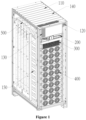
Figure 1 is a schematic perspective view showing a switchless uninterrupted power supply according to an embodiment of the present disclosure; -
Figure 2 is a top view of the switchless uninterrupted power supply after an incoming wire strip board is detached according to an embodiment of the present disclosure; -
Figure 3 is a schematic perspective view showing the switchless uninterrupted power supply after the incoming wire strip board is detached according to an embodiment of the present disclosure; -
Figure 4 is a left front view of the switchless uninterrupted power supply according to an embodiment of the present disclosure; -
Figure 5 is a right view of the switchless uninterrupted power supply according to an embodiment of the present disclosure; -
Figure 6 is a schematic diagram showing an input terminal of a by-pass module according to an embodiment of the present disclosure; and -
Figure 7 is a schematic diagram showing an output terminal of a by-pass module according to an embodiment of the present disclosure. - Reference symbols include:
100 cabinet, 110 power wire opening, 120 control wire opening, 130 internal cover plate and viewing window, 140 incoming wire strip board, 150 slide rail, 200 monitor module, 300 by-pass module, 400 power module, 500 wiring assembly, m main copper bar assembly mA first main copper bar, mB second main copper bar, mC third main copper bar, b by-pass copper bar assembly, bA first by-pass copper bar, bB second by-pass copper bar, bC third by-pass copper bar, o output copper bar assembly, oA first output copper bar, oB second output copper bar, oC third output copper bar, N neutral wire copper bar, PE ground copper bar, 520 battery wiring assembly, 521 anode wiring copper bar, 522 cathode wiring copper bar. - In order to clarify the technical problem to be solved, technical solutions, and beneficial effects of the present disclosure, hereinafter the present disclosure is described in further detail in conjunction with the drawings and embodiments. It should be understood that specific embodiments described herein are only used to illustrate the present disclosure, rather than limit the present disclosure.
- It should be noted that, an element, when described as being "fixed" or "arranged" on another element, may be arranged on the other element directly or indirectly. An element, when described as being "connected" to another element may be connected to the other element directly or indirectly.
- It should be understood that, orientations or positional relationships indicated by the terms such as "length", "width" "upper", "lower", "front", "back", "left", "right", "vertical", "horizontal", "top", "bottom", "inner", "outer" and the like are based on the orientations or positional relationships shown in the drawings. These terms are only used to facilitate the description of the present disclosure and to simplify the description, rather than indicate or imply that a device or element referred to must have a specific orientation or be arranged and operated in a specific orientation. Therefore, these terms should not be construed as a limitation to the present disclosure.
- Furthermore, the terms "first" and "second" are merely used for purpose of description, and should not be construed as indicating or implying relative importance or implying the number of the indicated technical features. Therefore, a feature defined by "first" and "second" may explicitly or implicitly be one or more in number. In the description of the present disclosure, "multiple" indicates two or more, unless specifically defined otherwise.
- Reference is made to
Figure 1 , which shows a preferred embodiment of the present disclosure. The switchless uninterrupted power supply includes acabinet 100, and awiring assembly 500, amonitor module 200, a by-pass module 300, and apower module 400 arranged in thecabinet 100. Thewiring assembly 500, themonitor module 200, the by-pass module 300 and thepower module 400 are arranged vertically. Apower wire opening 110 is formed on the top of thecabinet 100. Thewiring assembly 500 is arranged at thepower wire opening 110. Such a arrangement has a compact layout, provides a great power density, and is adaptable to various power distribution scenarios. Thewiring assembly 500 is directly connected in use, and time spent on assembly is reduced greatly. Each of the above components is introduced in further detail below. - As shown in
Figure 1 , thecabinet 100 is roughly a rectangular box as a whole. Themonitor module 200, the by-pass module 300, thepower module 400, thewiring assembly 500 and the like are arranged inside thecabinet 100. Thewiring assembly 500, themonitor module 200, the by-pass module 300 and thepower module 400 are arranged along a height direction of thecabinet 100. Multiple slide rails 150 are arranged on a side wall of thecabinet 100 near the front of thecabinet 100. Themonitor module 200, the by-pass module 300 and thepower module 400 are mounted on the slide rails 150 in a pullable manner. There aremultiple power modules 400. Themultiple power modules 400 are stacked along the height direction of thecabinet 100. The number of thepower module 400 is not limited in the present disclosure, and the number of thepower module 400 may be increased or decreased, depending on actual situations. - The
power wire opening 110 is formed at the top of thecabinet 100. A detachable incomingwire strip board 140 is arranged at thepower wire opening 110. Thewiring assembly 500 is arranged below the incomingwire strip board 140. Thewiring assembly 500 is exposed after the incomingwire strip board 140 is detached, thereby facilitating wiring. An internal cover plate andviewing window 130 and acontrol wire opening 120 are arranged at an upper part of a front face of thecabinet 100. The internal cover plate andviewing window 130 and thecontrol wire opening 120 are arranged corresponding to a height of thewiring assembly 500. The internal cover plate andviewing window 130 and thecontrol wire opening 120 are arranged along the depth direction of thecabinet 100 with thewiring assembly 500. - As shown in
Figure 2 and Figure 3 , in one of the embodiments of the present disclosure, thewiring assembly 500 includes a main copper bar assembly m, a by-pass copper bar assembly b, an output copper bar assembly o, a neutral wire bar N, a ground copper bar PE, and abattery wiring assembly 520. The by-pass copper bar assembly b and thebattery wiring assembly 520 are arranged at a front half portion in the depth direction of thecabinet 100. The main copper bar assembly m, the output copper bar assembly o, the neutral wire copper bar N and the ground copper bar PE are arranged at a back half portion in the depth direction of thecabinet 100. - Specifically, the main copper bar assembly m and the output copper bar assembly o are arranged oppositely in a width direction of the
cabinet 100. Each of the main copper bar assembly m and the output copper bar assembly o has a shape of "7" as a whole, and includes two parts connected together. First parts of the main copper bar assembly m and the output copper bar assembly o extend along the width direction of thecabinet 100. Second parts of the main copper bar assembly m and the output copper bar assembly o extend from the top of thecabinet 100 to the bottom of thecabinet 100. - Specifically, as shown in
Figure 2, Figure 3 andFigure 4 , the main copper bar assembly m includes a first main copper bar mA, a second main copper bar mB and a third main copper bar mC. The first main copper bar mA, the second main copper bar mB and the third main copper bar mC are arranged in parallel along the depth direction of thecabinet 100. As mentioned before, each of the first main copper bar mA, the second main copper bar mB and the third main copper bar mC has a shape of "7", and includes two parts connected together. That is, first parts of the first main copper bar mA, the second main copper bar mB and the third main copper bar mC extend along the width direction of thecabinet 100, and second parts of the first main copper bar mA, the second main copper bar mB and the third main copper bar mC extend from the top of thecabinet 100 to the bottom of thecabinet 100. - As shown in
Figure 2, Figure 3 andFigure 5 , the output copper bar assembly o includes a first output copper bar oA, a second output copper bar oB and a third output copper bar oC. The first output copper bar oA, the second output copper bar oB and the third output copper bar oC are arranged in parallel along the depth direction of thecabinet 100. As mentioned before, each of the first output copper bar oA, the second output copper bar oB and the third output copper bar oC has a shape of "7", and includes two parts connected together. That is, first parts of the first output copper bar oA, the second output copper bar oB and the third output copper bar oC extend along the width direction of thecabinet 100, and second parts of the first output copper bar oA, the second output copper bar oB and the third output copper bar oC extend from the top of thecabinet 100 to the bottom of thecabinet 100. - As shown in
Figure 2, Figure 3 andFigure 5 , the neutral wire copper bar N and the output copper bar assembly o are arranged in parallel along the depth direction of thecabinet 100. The neutral wire copper bar N extends along the height direction of thecabinet 100. That is, the neutral wire copper bar N is arranged in parallel with the second parts of the first output copperbar oA, the second output copper bar oB and the third output copper bar oC. Furthermore, the neutral wire copper bar N is closer to the by-pass copper bar assembly b than the second parts of the first output copper bar oA, the second output copper bar oB and the third output copper bar oC. - As shown in
Figure 2 and Figure 3 , the by-pass copper bar assembly b includes a first by-pass copper bar bA, a second by-pass copper bar bB and a third by-pass copper bar bC. The first by-pass copper bar bA, the second by-pass copper bar bB and the third by-pass copper bar bC are arranged in parallel along the width direction of thecabinet 100. Each of the first by-pass copper bar bA, the second by-pass copper bar bB and the third by-pass copper bar bC has a shape of "-", and extends along the depth direction of thecabinet 100. - The ground copper bar PE is arranged behind the main copper bar assembly m and the output copper bar assembly o in the depth direction of the
cabinet 100, and extends along the width direction of thecabinet 100. - The
battery wiring assembly 520 and the by-pass copper bar assembly b are arranged in parallel in the width direction of thecabinet 100, and are arranged at a front half portion of thecabinet 100. Thebattery wiring assembly 520 and the main copper bar assembly m are arranged in parallel along the depth direction of thecabinet 100. - As shown in
Figure 2, Figure 3 andFigure 4 , thebattery wiring assembly 520 includes an anodewiring copper bar 521 and a cathodewiring copper bar 522. The anodewiring copper bar 521 and the cathodewiring copper bar 522 each includes two parts connected together. First parts of the anodewiring copper bar 521 and the cathodewiring copper bar 522 extend along the depth direction of thecabinet 100. Second parts of the anodewiring copper bar 521 and the cathodewiring copper bar 522 extend from the top of thecabinet 100 to the bottom of thecabinet 100. - As shown in
Figure 6 and Figure 7 , an input terminal of the by-pass module 300 is connected to the by-pass copper bar assembly b arranged on the top of the by-pass module 300. An output terminal of the by-pass module 300 is connected to the second part of the output copper bar assembly o arranged at a rear portion of a side of the by-pass module 300. The input and output terminals of the by-pass module 300 each adopts full copper bar carriers, thereby decreasing cost and increasing efficiency of the device. - All the modules and the
wiring assembly 500 in the switchless uninterrupted power supply have a proper layout, which is convenient and secure for wiring. The layout of the main copper bar assembly m, the output copper bar assembly o, the by-pass copper bar assembly b, the neutral wire copper bar N, the ground copper bar PE and thebattery wiring assembly 520 improves the reliability of the system and the current sharing of the device. - Only preferred embodiments of the present disclosure are described above. Those have ordinary skills in the art can make various modifications to implementation manners and applications based on the idea of the present disclosure. All modifications that do not depart from the concept of the present disclosure fall into the scope of protection of the present disclosure.
Claims (12)
- A switchless uninterrupted power supply, characterized by comprising:a cabinet (100);a wiring assembly (500);a monitor module (200);a by-pass module (300); anda power module (400),wherein the wiring assembly (500), the monitor module (200), the by-pass module (300) and the power module (400) are arranged vertically in the cabinet (100), a power wire opening (110) is formed on a top of the cabinet (100), and the wiring assembly (500) is arranged at the power wire opening (110).
- The switchless uninterrupted power supply according to claim 1, characterized in that, the wiring assembly (500) comprises:a main copper bar assembly (m);a by-pass copper bar assembly (b);an output copper bar assembly (o); anda ground copper bar (PE),wherein the by-pass copper bar assembly (b) is arranged at a front half portion in a depth direction of the cabinet (100); andthe main copper bar assembly (m), the output copper bar assembly (o) and the ground copper bar (PE) are arranged at a back half portion in the depth direction of the cabinet (100).
- The switchless uninterrupted power supply according to claim 2, characterized in that, the main copper bar assembly (m) and the output copper bar assembly (o) are arranged oppositely in a width direction of the cabinet (100).
- The switchless uninterrupted power supply according to claim 3, characterized in that, the ground copper bar (PE) is arranged behind the main copper bar assembly (m) and the output copper bar assembly (o) in the depth direction of the cabinet (100).
- The switchless uninterrupted power supply according to claim 4, characterized in that, the wiring assembly (500) further comprises a battery wiring assembly (520), the battery wiring assembly (520) and the by-pass copper bar assembly (b) are arranged in parallel in the width direction of the cabinet (100), and are arranged at the front half portion of the cabinet (100), and
the battery wiring assembly (520) and the main copper bar assembly (m) are arranged in parallel along the depth direction of the cabinet (100). - The switchless uninterrupted power supply according to claim 5, characterized in that, the battery wiring assembly (520) comprises an anode wiring copper bar (521) and a cathode wiring copper bar (522), each of the anode wiring copper bar (521) and the cathode wiring copper bar (522) comprises two parts connected together, first parts of the anode wiring copper bar (521) and the cathode wiring copper bar (522) extend along the depth direction of the cabinet (100), and second parts of the anode wiring copper bar (521) and the cathode wiring copper bar (522) extend from the top of the cabinet (100) to a bottom of the cabinet (100).
- The switchless uninterrupted power supply according to claim 5, characterized in that the wiring assembly (500) further comprises a neutral wire copper bar (N), the neutral wire copper bar (N) and the output copper bar assembly (o) are arranged in parallel along the depth direction of the cabinet (100), and the neutral wire copper bar (N) extends along a height direction of the cabinet (100).
- The switchless uninterrupted power supply according to any one of claims 2 to 7, characterized in that, each of the main copper bar assembly (m) and the output copper bar assembly (o) comprises two parts connected together, first parts of the main copper bar assembly (m) and the output copper bar assembly (o) extend along a width direction of the cabinet (100), and second parts of the main copper bar assembly (m) and the output copper bar assembly (o) extend from the top of the cabinet (100) to a bottom of the cabinet (100).
- The switchless uninterrupted power supply according to claim 8, characterized in that, an input terminal of the by-pass module (300) is connected to the by-pass copper bar assembly (b) arranged on a top of the by-pass module (300), and an output terminal of the by-pass module (300) is connected to the second part of the output copper bar assembly (o) arranged at a rear portion of a side of the by-pass module (300).
- The switchless uninterrupted power supply according to claim 8, characterized in that, the main copper bar assembly (m) comprises a first main copper bar (mA), a second main copper bar (mB) and a third main copper bar (mC), and the first main copper bar (mA), the second main copper bar (mB) and the third main copper bar (mC) are arranged in parallel along the depth direction of the cabinet (100).
- The switchless uninterrupted power supply according to claim 8, characterized in that, the output copper bar assembly (o) comprises a first output copper bar (oA), a second output copper bar (oB) and a third output copper bar (oC), and the first output copper bar (oA), the second output copper bar (oB) and the third output copper bar (oC) are arranged in parallel along the depth direction of the cabinet (100).
- The switchless uninterrupted power supply according to any one of claims 9 to 11, characterized in that, the by-pass copper bar assembly (b) comprises a first by-pass copper bar (bA), a second by-pass copper bar (bB) and a third by-pass copper bar (bC), and the first by-pass copper bar (bA), the second by-pass copper bar (bB) and the third by-pass copper bar (bC) are arranged in parallel along the width direction of the cabinet (100).
Applications Claiming Priority (1)
| Application Number | Priority Date | Filing Date | Title |
|---|---|---|---|
| CN202322477803.3U CN220857701U (en) | 2023-09-12 | 2023-09-12 | A switchless uninterruptible power supply |
Publications (1)
| Publication Number | Publication Date |
|---|---|
| EP4525266A1 true EP4525266A1 (en) | 2025-03-19 |
Family
ID=90781453
Family Applications (1)
| Application Number | Title | Priority Date | Filing Date |
|---|---|---|---|
| EP24175085.0A Pending EP4525266A1 (en) | 2023-09-12 | 2024-05-09 | Switchless uninterrupted power supply |
Country Status (2)
| Country | Link |
|---|---|
| EP (1) | EP4525266A1 (en) |
| CN (1) | CN220857701U (en) |
Citations (2)
| Publication number | Priority date | Publication date | Assignee | Title |
|---|---|---|---|---|
| US20200059163A1 (en) * | 2017-11-14 | 2020-02-20 | Fuji Electric Co., Ltd. | Power conversion device |
| CN218632926U (en) * | 2022-11-08 | 2023-03-14 | 维谛公司 | Uninterrupted power source cabinet |
-
2023
- 2023-09-12 CN CN202322477803.3U patent/CN220857701U/en active Active
-
2024
- 2024-05-09 EP EP24175085.0A patent/EP4525266A1/en active Pending
Patent Citations (2)
| Publication number | Priority date | Publication date | Assignee | Title |
|---|---|---|---|---|
| US20200059163A1 (en) * | 2017-11-14 | 2020-02-20 | Fuji Electric Co., Ltd. | Power conversion device |
| CN218632926U (en) * | 2022-11-08 | 2023-03-14 | 维谛公司 | Uninterrupted power source cabinet |
Also Published As
| Publication number | Publication date |
|---|---|
| CN220857701U (en) | 2024-04-26 |
Similar Documents
| Publication | Publication Date | Title |
|---|---|---|
| EP4232870B1 (en) | Forced air cooling for display assemblies | |
| US4321654A (en) | Frame unit for electronic communication devices | |
| US6361897B1 (en) | Dual terminal battery for modular power supply and power supply | |
| US6545850B1 (en) | Backplane power landing system | |
| US5062801A (en) | Function unit in which circuit boards are mounted on a center plane by way of distribution boards | |
| US7688027B2 (en) | Portable battery charger to charge plural batteries | |
| CN218569143U (en) | a power storage system | |
| US11711900B2 (en) | Display panel and display module | |
| US10512188B2 (en) | Line, arrangement and server insert | |
| CN201509094U (en) | Hot swap structure for UPS module and UPS cabinet | |
| CN204651929U (en) | A kind of power model | |
| CN106159964B (en) | Power module | |
| US20220294055A1 (en) | Battery bank with unitary battery terminal connector straps | |
| CN220857701U (en) | A switchless uninterruptible power supply | |
| CN215581057U (en) | Photovoltaic junction box mounting structure | |
| CN216436815U (en) | Series water-cooling SVG power module and SVG equipment | |
| CN217720786U (en) | Bidirectional charging and discharging machine | |
| EP4531507A1 (en) | Uninterrupted power supply | |
| CN219696634U (en) | Battery pack positioning clamping plate, battery pack positioning clamping plate assembly and battery pack | |
| CN223552112U (en) | Stacked bar code reading module | |
| US20240413510A1 (en) | Battery device | |
| CN113838493A (en) | Hard disk mounting mechanism, hard disk assembly and electronic equipment | |
| CN221767861U (en) | Urban rail T-type three-level bidirectional converter power module symmetrically stacked busbar | |
| CN218334148U (en) | PDU power supply case structure | |
| CN221408665U (en) | Modularized energy storage converter |
Legal Events
| Date | Code | Title | Description |
|---|---|---|---|
| PUAI | Public reference made under article 153(3) epc to a published international application that has entered the european phase |
Free format text: ORIGINAL CODE: 0009012 |
|
| STAA | Information on the status of an ep patent application or granted ep patent |
Free format text: STATUS: THE APPLICATION HAS BEEN PUBLISHED |
|
| AK | Designated contracting states |
Kind code of ref document: A1 Designated state(s): AL AT BE BG CH CY CZ DE DK EE ES FI FR GB GR HR HU IE IS IT LI LT LU LV MC ME MK MT NL NO PL PT RO RS SE SI SK SM TR |
|
| STAA | Information on the status of an ep patent application or granted ep patent |
Free format text: STATUS: REQUEST FOR EXAMINATION WAS MADE |
|
| 17P | Request for examination filed |
Effective date: 20250911 |