EP4525265A2 - Power-saving type apparatus and method for managing battery - Google Patents
Power-saving type apparatus and method for managing battery Download PDFInfo
- Publication number
- EP4525265A2 EP4525265A2 EP24221583.8A EP24221583A EP4525265A2 EP 4525265 A2 EP4525265 A2 EP 4525265A2 EP 24221583 A EP24221583 A EP 24221583A EP 4525265 A2 EP4525265 A2 EP 4525265A2
- Authority
- EP
- European Patent Office
- Prior art keywords
- battery
- control unit
- state
- charge
- motor
- Prior art date
- Legal status (The legal status is an assumption and is not a legal conclusion. Google has not performed a legal analysis and makes no representation as to the accuracy of the status listed.)
- Pending
Links
Images




Classifications
-
- H—ELECTRICITY
- H02—GENERATION; CONVERSION OR DISTRIBUTION OF ELECTRIC POWER
- H02J—ELECTRIC POWER NETWORKS; CIRCUIT ARRANGEMENTS OR SYSTEMS FOR SUPPLYING OR DISTRIBUTING ELECTRIC POWER; SYSTEMS FOR STORING ELECTRIC ENERGY
- H02J7/00—Circuit arrangements for charging or discharging batteries or for supplying loads from batteries
- H02J7/80—Circuit arrangements for charging or discharging batteries or for supplying loads from batteries including monitoring or indicating arrangements
-
- B—PERFORMING OPERATIONS; TRANSPORTING
- B60—VEHICLES IN GENERAL
- B60L—PROPULSION OF ELECTRICALLY-PROPELLED VEHICLES; SUPPLYING ELECTRIC POWER FOR AUXILIARY EQUIPMENT OF ELECTRICALLY-PROPELLED VEHICLES; ELECTRODYNAMIC BRAKE SYSTEMS FOR VEHICLES IN GENERAL; MAGNETIC SUSPENSION OR LEVITATION FOR VEHICLES; MONITORING OPERATING VARIABLES OF ELECTRICALLY-PROPELLED VEHICLES; ELECTRIC SAFETY DEVICES FOR ELECTRICALLY-PROPELLED VEHICLES
- B60L3/00—Electric devices on electrically-propelled vehicles for safety purposes; Monitoring operating variables, e.g. speed, deceleration or energy consumption
- B60L3/0023—Detecting, eliminating, remedying or compensating for drive train abnormalities, e.g. failures within the drive train
- B60L3/0046—Detecting, eliminating, remedying or compensating for drive train abnormalities, e.g. failures within the drive train relating to electric energy storage systems, e.g. batteries or capacitors
-
- B—PERFORMING OPERATIONS; TRANSPORTING
- B60—VEHICLES IN GENERAL
- B60L—PROPULSION OF ELECTRICALLY-PROPELLED VEHICLES; SUPPLYING ELECTRIC POWER FOR AUXILIARY EQUIPMENT OF ELECTRICALLY-PROPELLED VEHICLES; ELECTRODYNAMIC BRAKE SYSTEMS FOR VEHICLES IN GENERAL; MAGNETIC SUSPENSION OR LEVITATION FOR VEHICLES; MONITORING OPERATING VARIABLES OF ELECTRICALLY-PROPELLED VEHICLES; ELECTRIC SAFETY DEVICES FOR ELECTRICALLY-PROPELLED VEHICLES
- B60L3/00—Electric devices on electrically-propelled vehicles for safety purposes; Monitoring operating variables, e.g. speed, deceleration or energy consumption
- B60L3/0023—Detecting, eliminating, remedying or compensating for drive train abnormalities, e.g. failures within the drive train
- B60L3/0061—Detecting, eliminating, remedying or compensating for drive train abnormalities, e.g. failures within the drive train relating to electrical machines
-
- B—PERFORMING OPERATIONS; TRANSPORTING
- B60—VEHICLES IN GENERAL
- B60L—PROPULSION OF ELECTRICALLY-PROPELLED VEHICLES; SUPPLYING ELECTRIC POWER FOR AUXILIARY EQUIPMENT OF ELECTRICALLY-PROPELLED VEHICLES; ELECTRODYNAMIC BRAKE SYSTEMS FOR VEHICLES IN GENERAL; MAGNETIC SUSPENSION OR LEVITATION FOR VEHICLES; MONITORING OPERATING VARIABLES OF ELECTRICALLY-PROPELLED VEHICLES; ELECTRIC SAFETY DEVICES FOR ELECTRICALLY-PROPELLED VEHICLES
- B60L3/00—Electric devices on electrically-propelled vehicles for safety purposes; Monitoring operating variables, e.g. speed, deceleration or energy consumption
- B60L3/12—Recording operating variables ; Monitoring of operating variables
-
- B—PERFORMING OPERATIONS; TRANSPORTING
- B60—VEHICLES IN GENERAL
- B60L—PROPULSION OF ELECTRICALLY-PROPELLED VEHICLES; SUPPLYING ELECTRIC POWER FOR AUXILIARY EQUIPMENT OF ELECTRICALLY-PROPELLED VEHICLES; ELECTRODYNAMIC BRAKE SYSTEMS FOR VEHICLES IN GENERAL; MAGNETIC SUSPENSION OR LEVITATION FOR VEHICLES; MONITORING OPERATING VARIABLES OF ELECTRICALLY-PROPELLED VEHICLES; ELECTRIC SAFETY DEVICES FOR ELECTRICALLY-PROPELLED VEHICLES
- B60L58/00—Methods or circuit arrangements for monitoring or controlling batteries or fuel cells, specially adapted for electric vehicles
- B60L58/10—Methods or circuit arrangements for monitoring or controlling batteries or fuel cells, specially adapted for electric vehicles for monitoring or controlling batteries
-
- B—PERFORMING OPERATIONS; TRANSPORTING
- B60—VEHICLES IN GENERAL
- B60L—PROPULSION OF ELECTRICALLY-PROPELLED VEHICLES; SUPPLYING ELECTRIC POWER FOR AUXILIARY EQUIPMENT OF ELECTRICALLY-PROPELLED VEHICLES; ELECTRODYNAMIC BRAKE SYSTEMS FOR VEHICLES IN GENERAL; MAGNETIC SUSPENSION OR LEVITATION FOR VEHICLES; MONITORING OPERATING VARIABLES OF ELECTRICALLY-PROPELLED VEHICLES; ELECTRIC SAFETY DEVICES FOR ELECTRICALLY-PROPELLED VEHICLES
- B60L58/00—Methods or circuit arrangements for monitoring or controlling batteries or fuel cells, specially adapted for electric vehicles
- B60L58/10—Methods or circuit arrangements for monitoring or controlling batteries or fuel cells, specially adapted for electric vehicles for monitoring or controlling batteries
- B60L58/12—Methods or circuit arrangements for monitoring or controlling batteries or fuel cells, specially adapted for electric vehicles for monitoring or controlling batteries responding to state of charge [SoC]
-
- G—PHYSICS
- G01—MEASURING; TESTING
- G01R—MEASURING ELECTRIC VARIABLES; MEASURING MAGNETIC VARIABLES
- G01R31/00—Arrangements for testing electric properties; Arrangements for locating electric faults; Arrangements for electrical testing characterised by what is being tested not provided for elsewhere
- G01R31/34—Testing dynamo-electric machines
-
- G—PHYSICS
- G01—MEASURING; TESTING
- G01R—MEASURING ELECTRIC VARIABLES; MEASURING MAGNETIC VARIABLES
- G01R31/00—Arrangements for testing electric properties; Arrangements for locating electric faults; Arrangements for electrical testing characterised by what is being tested not provided for elsewhere
- G01R31/36—Arrangements for testing, measuring or monitoring the electrical condition of accumulators or electric batteries, e.g. capacity or state of charge [SoC]
- G01R31/382—Arrangements for monitoring battery or accumulator variables, e.g. SoC
-
- H—ELECTRICITY
- H01—ELECTRIC ELEMENTS
- H01M—PROCESSES OR MEANS, e.g. BATTERIES, FOR THE DIRECT CONVERSION OF CHEMICAL ENERGY INTO ELECTRICAL ENERGY
- H01M10/00—Secondary cells; Manufacture thereof
- H01M10/42—Methods or arrangements for servicing or maintenance of secondary cells or secondary half-cells
-
- H—ELECTRICITY
- H01—ELECTRIC ELEMENTS
- H01M—PROCESSES OR MEANS, e.g. BATTERIES, FOR THE DIRECT CONVERSION OF CHEMICAL ENERGY INTO ELECTRICAL ENERGY
- H01M10/00—Secondary cells; Manufacture thereof
- H01M10/42—Methods or arrangements for servicing or maintenance of secondary cells or secondary half-cells
- H01M10/4207—Methods or arrangements for servicing or maintenance of secondary cells or secondary half-cells for several batteries or cells simultaneously or sequentially
-
- H—ELECTRICITY
- H01—ELECTRIC ELEMENTS
- H01M—PROCESSES OR MEANS, e.g. BATTERIES, FOR THE DIRECT CONVERSION OF CHEMICAL ENERGY INTO ELECTRICAL ENERGY
- H01M10/00—Secondary cells; Manufacture thereof
- H01M10/42—Methods or arrangements for servicing or maintenance of secondary cells or secondary half-cells
- H01M10/425—Structural combination with electronic components, e.g. electronic circuits integrated to the outside of the casing
-
- H—ELECTRICITY
- H01—ELECTRIC ELEMENTS
- H01M—PROCESSES OR MEANS, e.g. BATTERIES, FOR THE DIRECT CONVERSION OF CHEMICAL ENERGY INTO ELECTRICAL ENERGY
- H01M10/00—Secondary cells; Manufacture thereof
- H01M10/42—Methods or arrangements for servicing or maintenance of secondary cells or secondary half-cells
- H01M10/48—Accumulators combined with arrangements for measuring, testing or indicating the condition of cells, e.g. the level or density of the electrolyte
-
- H—ELECTRICITY
- H01—ELECTRIC ELEMENTS
- H01M—PROCESSES OR MEANS, e.g. BATTERIES, FOR THE DIRECT CONVERSION OF CHEMICAL ENERGY INTO ELECTRICAL ENERGY
- H01M10/00—Secondary cells; Manufacture thereof
- H01M10/42—Methods or arrangements for servicing or maintenance of secondary cells or secondary half-cells
- H01M10/48—Accumulators combined with arrangements for measuring, testing or indicating the condition of cells, e.g. the level or density of the electrolyte
- H01M10/482—Accumulators combined with arrangements for measuring, testing or indicating the condition of cells, e.g. the level or density of the electrolyte for several batteries or cells simultaneously or sequentially
-
- H—ELECTRICITY
- H02—GENERATION; CONVERSION OR DISTRIBUTION OF ELECTRIC POWER
- H02J—ELECTRIC POWER NETWORKS; CIRCUIT ARRANGEMENTS OR SYSTEMS FOR SUPPLYING OR DISTRIBUTING ELECTRIC POWER; SYSTEMS FOR STORING ELECTRIC ENERGY
- H02J7/00—Circuit arrangements for charging or discharging batteries or for supplying loads from batteries
- H02J7/14—Circuit arrangements for charging or discharging batteries or for supplying loads from batteries for charging batteries from dynamo-electric generators driven at varying speed, e.g. on vehicle
- H02J7/1446—Circuit arrangements for charging or discharging batteries or for supplying loads from batteries for charging batteries from dynamo-electric generators driven at varying speed, e.g. on vehicle in response to parameters of a vehicle
-
- H—ELECTRICITY
- H02—GENERATION; CONVERSION OR DISTRIBUTION OF ELECTRIC POWER
- H02J—ELECTRIC POWER NETWORKS; CIRCUIT ARRANGEMENTS OR SYSTEMS FOR SUPPLYING OR DISTRIBUTING ELECTRIC POWER; SYSTEMS FOR STORING ELECTRIC ENERGY
- H02J7/00—Circuit arrangements for charging or discharging batteries or for supplying loads from batteries
- H02J7/40—Circuit arrangements for charging or discharging batteries or for supplying loads from batteries characterised by the exchange of charge or discharge related data
-
- H—ELECTRICITY
- H02—GENERATION; CONVERSION OR DISTRIBUTION OF ELECTRIC POWER
- H02J—ELECTRIC POWER NETWORKS; CIRCUIT ARRANGEMENTS OR SYSTEMS FOR SUPPLYING OR DISTRIBUTING ELECTRIC POWER; SYSTEMS FOR STORING ELECTRIC ENERGY
- H02J7/00—Circuit arrangements for charging or discharging batteries or for supplying loads from batteries
- H02J7/40—Circuit arrangements for charging or discharging batteries or for supplying loads from batteries characterised by the exchange of charge or discharge related data
- H02J7/44—Circuit arrangements for charging or discharging batteries or for supplying loads from batteries characterised by the exchange of charge or discharge related data between battery management systems and power sources
-
- H—ELECTRICITY
- H02—GENERATION; CONVERSION OR DISTRIBUTION OF ELECTRIC POWER
- H02J—ELECTRIC POWER NETWORKS; CIRCUIT ARRANGEMENTS OR SYSTEMS FOR SUPPLYING OR DISTRIBUTING ELECTRIC POWER; SYSTEMS FOR STORING ELECTRIC ENERGY
- H02J7/00—Circuit arrangements for charging or discharging batteries or for supplying loads from batteries
- H02J7/80—Circuit arrangements for charging or discharging batteries or for supplying loads from batteries including monitoring or indicating arrangements
- H02J7/82—Control of state of charge [SOC]
-
- B—PERFORMING OPERATIONS; TRANSPORTING
- B60—VEHICLES IN GENERAL
- B60Y—INDEXING SCHEME RELATING TO ASPECTS CROSS-CUTTING VEHICLE TECHNOLOGY
- B60Y2200/00—Type of vehicle
- B60Y2200/90—Vehicles comprising electric prime movers
- B60Y2200/91—Electric vehicles
-
- G—PHYSICS
- G01—MEASURING; TESTING
- G01R—MEASURING ELECTRIC VARIABLES; MEASURING MAGNETIC VARIABLES
- G01R31/00—Arrangements for testing electric properties; Arrangements for locating electric faults; Arrangements for electrical testing characterised by what is being tested not provided for elsewhere
- G01R31/36—Arrangements for testing, measuring or monitoring the electrical condition of accumulators or electric batteries, e.g. capacity or state of charge [SoC]
- G01R31/367—Software therefor, e.g. for battery testing using modelling or look-up tables
-
- G—PHYSICS
- G01—MEASURING; TESTING
- G01R—MEASURING ELECTRIC VARIABLES; MEASURING MAGNETIC VARIABLES
- G01R31/00—Arrangements for testing electric properties; Arrangements for locating electric faults; Arrangements for electrical testing characterised by what is being tested not provided for elsewhere
- G01R31/36—Arrangements for testing, measuring or monitoring the electrical condition of accumulators or electric batteries, e.g. capacity or state of charge [SoC]
- G01R31/371—Arrangements for testing, measuring or monitoring the electrical condition of accumulators or electric batteries, e.g. capacity or state of charge [SoC] with remote indication, e.g. on external chargers
-
- H—ELECTRICITY
- H01—ELECTRIC ELEMENTS
- H01M—PROCESSES OR MEANS, e.g. BATTERIES, FOR THE DIRECT CONVERSION OF CHEMICAL ENERGY INTO ELECTRICAL ENERGY
- H01M10/00—Secondary cells; Manufacture thereof
- H01M10/42—Methods or arrangements for servicing or maintenance of secondary cells or secondary half-cells
- H01M10/425—Structural combination with electronic components, e.g. electronic circuits integrated to the outside of the casing
- H01M2010/4271—Battery management systems including electronic circuits, e.g. control of current or voltage to keep battery in healthy state, cell balancing
-
- H—ELECTRICITY
- H01—ELECTRIC ELEMENTS
- H01M—PROCESSES OR MEANS, e.g. BATTERIES, FOR THE DIRECT CONVERSION OF CHEMICAL ENERGY INTO ELECTRICAL ENERGY
- H01M10/00—Secondary cells; Manufacture thereof
- H01M10/42—Methods or arrangements for servicing or maintenance of secondary cells or secondary half-cells
- H01M10/425—Structural combination with electronic components, e.g. electronic circuits integrated to the outside of the casing
- H01M2010/4278—Systems for data transfer from batteries, e.g. transfer of battery parameters to a controller, data transferred between battery controller and main controller
-
- H—ELECTRICITY
- H02—GENERATION; CONVERSION OR DISTRIBUTION OF ELECTRIC POWER
- H02J—ELECTRIC POWER NETWORKS; CIRCUIT ARRANGEMENTS OR SYSTEMS FOR SUPPLYING OR DISTRIBUTING ELECTRIC POWER; SYSTEMS FOR STORING ELECTRIC ENERGY
- H02J2105/00—Networks for supplying or distributing electric power characterised by their spatial reach or by the load
- H02J2105/30—Networks for supplying or distributing electric power characterised by their spatial reach or by the load the load networks being external to vehicles, i.e. exchanging power with vehicles
- H02J2105/33—Networks for supplying or distributing electric power characterised by their spatial reach or by the load the load networks being external to vehicles, i.e. exchanging power with vehicles exchanging power with road vehicles
- H02J2105/37—Networks for supplying or distributing electric power characterised by their spatial reach or by the load the load networks being external to vehicles, i.e. exchanging power with vehicles exchanging power with road vehicles exchanging power with electric vehicles [EV] or with hybrid electric vehicles [HEV]
-
- Y—GENERAL TAGGING OF NEW TECHNOLOGICAL DEVELOPMENTS; GENERAL TAGGING OF CROSS-SECTIONAL TECHNOLOGIES SPANNING OVER SEVERAL SECTIONS OF THE IPC; TECHNICAL SUBJECTS COVERED BY FORMER USPC CROSS-REFERENCE ART COLLECTIONS [XRACs] AND DIGESTS
- Y02—TECHNOLOGIES OR APPLICATIONS FOR MITIGATION OR ADAPTATION AGAINST CLIMATE CHANGE
- Y02E—REDUCTION OF GREENHOUSE GAS [GHG] EMISSIONS, RELATED TO ENERGY GENERATION, TRANSMISSION OR DISTRIBUTION
- Y02E60/00—Enabling technologies; Technologies with a potential or indirect contribution to GHG emissions mitigation
- Y02E60/10—Energy storage using batteries
-
- Y—GENERAL TAGGING OF NEW TECHNOLOGICAL DEVELOPMENTS; GENERAL TAGGING OF CROSS-SECTIONAL TECHNOLOGIES SPANNING OVER SEVERAL SECTIONS OF THE IPC; TECHNICAL SUBJECTS COVERED BY FORMER USPC CROSS-REFERENCE ART COLLECTIONS [XRACs] AND DIGESTS
- Y02—TECHNOLOGIES OR APPLICATIONS FOR MITIGATION OR ADAPTATION AGAINST CLIMATE CHANGE
- Y02T—CLIMATE CHANGE MITIGATION TECHNOLOGIES RELATED TO TRANSPORTATION
- Y02T10/00—Road transport of goods or passengers
- Y02T10/60—Other road transportation technologies with climate change mitigation effect
- Y02T10/70—Energy storage systems for electromobility, e.g. batteries
-
- Y—GENERAL TAGGING OF NEW TECHNOLOGICAL DEVELOPMENTS; GENERAL TAGGING OF CROSS-SECTIONAL TECHNOLOGIES SPANNING OVER SEVERAL SECTIONS OF THE IPC; TECHNICAL SUBJECTS COVERED BY FORMER USPC CROSS-REFERENCE ART COLLECTIONS [XRACs] AND DIGESTS
- Y02—TECHNOLOGIES OR APPLICATIONS FOR MITIGATION OR ADAPTATION AGAINST CLIMATE CHANGE
- Y02T—CLIMATE CHANGE MITIGATION TECHNOLOGIES RELATED TO TRANSPORTATION
- Y02T10/00—Road transport of goods or passengers
- Y02T10/80—Technologies aiming to reduce greenhouse gasses emissions common to all road transportation technologies
- Y02T10/92—Energy efficient charging or discharging systems for batteries, ultracapacitors, supercapacitors or double-layer capacitors specially adapted for vehicles
Definitions
- the present invention relates to a power-saving type apparatus and method for managing a battery, which control the sensing cycle and transmission power of a battery management system based on the state of a motor and a battery of a vehicle.
- ESS energy storage system
- BMS battery management system
- an application specific integrated circuit (ASIC) inside the battery management system reads battery cell state information according to a predetermined sensing cycle, and has a problem of consuming current to receive battery cell information switched from a sleep mode even when battery consumption is not large.
- ASIC application specific integrated circuit
- the battery management system reads battery cell state information according to a predetermined sensing cycle, and has a problem of consuming current to receive battery cell information switched from a sleep mode even when battery consumption is not large.
- the wireless transmission power of a master device and a slave device, which perform wireless communication are set to a maximum value in order to minimize data loss.
- JP 2019-504450 A and US 2019/176642 A1 Further background art is described in JP 2019-504450 A and US 2019/176642 A1 .
- An aspect of the present invention is to provide a power-saving type apparatus and method for managing a battery, which actively control the sensing cycle and transmission power of a battery management system according to the state of the use of a battery, thereby minimizing the amount of battery consumption in a wireless battery management system to use power efficiently.
- a battery management apparatus including a battery control unit for receiving the operation state of a motor detected and detecting the state of charge of a battery, and a condition control unit for applying a weight to at least one of the operation state of the motor and the state of charge of the battery to adjust operation conditions of the battery control unit and allowing the battery control unit to operate on the basis of the adjusted operation conditions. operation conditions.
- the operation conditions of the battery management apparatus may include the sensing cycle of the battery, and the condition control unit may adjust a preset sensing cycle of the battery and allow the battery control unit to monitor the battery according to the adjusted sensing cycle.
- the operation conditions of the battery management apparatus may include the transmission power of the battery control unit, and the condition control unit may adjust preset transmission power of the battery control unit and allow the battery control unit to transmit a signal according to the adjusted transmission power.
- condition control unit may adjust preset transmission power of the battery control unit and allow the battery control unit to transmit a signal according to the adjusted transmission power.
- the condition control unit of the battery management apparatus may control the operations condition of the battery control unit using a fuzzy function.
- the weight of the battery management apparatus may be determined for each preset range of the operation state of the motor and the state of charge of the battery.
- the battery control unit of the battery management apparatus may receive the operation state of the motor from a motor sensing unit or a higher-level controller of a vehicle.
- the battery management apparatus may further include a charge control unit for controlling the charging of the battery, wherein the state of charge of the battery may be either directly transmitted from the charge control unit to the battery control unit, or transmitted from the higher-level controller, and then transmitted from the higher-level controller to the battery control unit.
- a battery management method including receiving the operation state of a motor detected, detecting the state of charge of a battery, and applying a weight to at least one of the operation state of the motor and the state of charge of the battery to adjust operation conditions of a battery control unit.
- the operation conditions of the battery management method may include the sensing cycle of the battery, and the adjusting of the operation conditions of the battery control unit may adjust a preset sensing cycle of the battery and allow the battery control unit to perform monitoring the battery according to the adjusted sensing cycle.
- the adjusting of the operation conditions of the battery control unit may adjust a preset sensing cycle of the battery and allow the battery control unit to perform monitoring the battery according to the adjusted sensing cycle.
- the operation conditions of the battery management method may include the transmission power of the battery control unit, and the adjusting of the operation conditions of the battery control unit may adjust preset transmission power of the battery control unit and allow the battery control unit to transmit a signal according to the adjusted transmission power.
- the sensing cycle and transmission power of a battery management system is actively controlled according to the state of the use of a battery, so that the amount of battery consumption is minimized in a wireless battery management system, making it possible to use power efficiently.
- Terms such as "a first,” “a second,” “first,” and “second” used in various embodiments may modify various components regardless of the order and/or importance thereof, and do not limited the corresponding components.
- a first component may be referred to as a second component without departing from the scope of the present invention, and similarly, a second component may also be referred to as a first component. also be referred to as a first component.
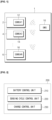
- FIG. 1 is a configuration diagram of a battery pack including a battery management system according to an embodiment of the present invention.
- a plurality of battery cells 2, 4, and 6 are connected either in series or in parallel.
- slave battery management systems 12, 14, and 16 are respectively disposed.
- Each slave battery management system 12, 14, and 16 performs monitoring by measuring the temperature, voltage, or current of the plurality of battery cells 2, 4, and 6, transmits information obtained by the monitoring to a higher-level system, and receives a battery cell control command from the higher-level to control connected battery cells.
- the plurality of battery cells 2, 4, and 6 are connected either in series or in parallel to form the battery module 1.
- a master battery management system 10 is disposed.
- the master battery management system 10 performs monitoring by measuring the temperature, voltage, or current of the battery module 1.
- the master battery management system 10 receives monitoring information of each battery cell from the slave battery management systems 12, 14, and 16 disposed in each battery cell and transmits the same to a higher-level system, and receives a specific task performance command from the higher-level system and transmits the same to corresponding slave battery management systems 12, 14, and 16.
- battery cell and transmits the same to a higher-level system, and receives a specific task performance command from the higher-level system and transmits the same to corresponding slave battery management systems 12, 14, and 16.
- a battery management apparatus 200 may include a battery control unit 210, a sensing cycle control unit 220, and a charge control unit 230. At this time, the battery management apparatus 200 may correspond to both the master battery management system and the slave battery management system of FIG. 1 .
- a condition control unit of the battery management apparatus 200 according to an embodiment of the present invention may be represented by the sensing cycle control unit 220.
- esent invention may be represented by the sensing cycle control unit 220.
- the battery control unit 210 may receive the operation state of a motor detected, and may detect the state of charge of a battery. In this case, the battery control unit 210 may receive the operation state of the motor directly from a motor sensing unit (not shown) which detects the operation of a motor of a vehicle, or may receive the operation state of the motor from a higher-level controller.
- the battery control unit 210 may perform monitoring of the battery, and may adjust the sensing cycle of the battery or the transmission power of a signal according to the state of the battery or the motor.
- the sensing cycle control unit 220 may adjust a preset sensing cycle of a battery by applying a weight to at least one of the operation state of the motor received from the battery control unit 210 and the state of charge of the battery detected therefrom. At this time, the weight may be determined for each preset range of the operation state of the motor and the state of charge of the battery. This will be described later in detail with reference to FIG. 3 . will be described later in detail with reference to FIG. 3 .
- the sensing cycle control unit 220 may allow the battery control unit 210 to perform monitoring a battery according to the adjusted sensing cycle.
- the sensing cycle control unit 220 may use a fuzzy function to adjust the sensing cycle of the battery as to be described later.
- ge control unit 230 may transmit the state of charge of the battery to a higher-level controller, and then allow the same to be transmitted from the higher-level controller to the battery control unit 210.
- the sensing cycle and transmission power of a battery management system is actively controlled according to the state of the use of a battery, so that the amount of battery consumption is minimized in a wireless battery management system, making it possible to use power efficiently.
- FIG. 3 is a diagram showing a method for calculating a sensing cycle in a battery management apparatus according to an embodiment of the present invention.
- a weight graph (a) for the load (speed) of a motor a weight graph (b) for the SOC of a battery, and a final sensing cycle (c) obtained by combining (1) and (b) are shown.
- the graphs of FIG. 3 are only exemplary.
- a weight may be calculated in various manners for each case.
- the speed of a motor may be classified according to a fuzzy rule into ranges of very high (120 km/h or greater), high (80 km/h to 120 km/h), normal (40 km/h to 80 km/h), low (20 km/h to 40 km/h), very low or stop (20km/h or less).
- ight for the sensing cycle may be increased to confirm the state of the battery quickly.
- FIG. 3 means that the weight for the load (speed) of a motor and the weight for the SOC of a battery are summed.
- FIG. 3 is not limited to a logical operation AND only.
- a logical operation OR may also be applied according to an algorithm, and various operations such as +, x, Min, and Max may be applied.
- FIG. 4 is a flowchart showing a battery management method according to an embodiment of the present invention.
- battery control unit 210 detects the state of charge of a battery S420.
- the state of charge of the battery may be detected by a separate charge control unit 230.
- the state of charge of the battery may be transmitted directly to the battery control unit 210 from the charge control unit 230, or may be transmitted to the battery control unit 210 through a higher-level controller.
- a preset sensing cycle of the battery may be adjusted by applying a weight to at least one of the detected operation state of the motor and the detected state of charge of the battery S430.
- the sensing cycle of the battery may be adjusted using a fuzzy function.
- the weight for adjusting a sensing cycle may be applied to each range after dividing the operation state of the motor and the state of charge of the battery into a predetermined range.
- the sensing cycle of the battery may be adjusted using a fuzzy function.
- the weight for adjusting a sensing cycle may be applied to each range after dividing the operation state of the motor and the state of charge of the battery into a predetermined range.
- the battery control unit 210 performs monitoring of the battery according to the adjusted sensing cycle S440.
- the sensing cycle of a battery may be actively changed according to the state of the use of the battery, so that power may be efficiently used.
- the sensing cycle of a battery may be actively changed according to the state of the use of the battery, so that power may be efficiently used.
- FIG. 5 is a block diagram showing a configuration of a battery management apparatus according another an embodiment of the present invention.
- a battery management apparatus 500 may include a battery control unit 510, a transmission power control unit 520, and a charge control unit 530.
- a condition control unit of the battery management apparatus 200 according to an embodiment of the present invention may be represented by the transmission power control unit 520.
- the battery control unit 510 may receive the operation state of a motor detected, and may detect the state of charge of a battery. In this case, the battery control unit 510 may receive the operation state of the motor directly from a motor sensing unit (not shown) which detects the operation of a motor of a vehicle, or may receive the operation state of the motor from a higher-level controller.
- the battery control unit 510 may perform monitoring of the battery, and may adjust the sensing cycle of the battery or the transmission power of a signal according to the state of the battery or the motor.
- the transmission power control unit 520 may adjust a preset transmission power of the battery control unit 510 by applying a weight to at least one of the operation state of the motor received from the battery control unit 510 and the state of charge of the battery detected therefrom. At this time, the weight may be determined for each preset range of the operation state of the motor and the state of charge of the battery. This will be described later in detail with reference to FIG. 6 .
- the transmission power control unit 520 may allow the battery control unit 510 to transmit a signal with transmission power.
- the transmission power control unit 520 may use a fuzzy function to adjust the transmission power of the battery control unit 510 as to be described later.
- the charge control unit 530 may control the charging of a battery.
- the charge control unit 530 may transmit the state of charge of the battery directly to the battery control unit 510.
- the charge control unit 530 may transmit the state of charge of the battery to a higher-level controller, and then allow the same to be transmitted from the higher-level controller to the battery control unit 510.
- charge control unit 530 may transmit the state of charge of the battery to a higher-level controller, and then allow the same to be transmitted from the higher-level controller to the battery control unit 510.
- the sensing cycle and transmission power of a battery management system is actively controlled according to the state of the use of a battery, so that the amount of battery consumption is minimized in a wireless battery management system, making it possible to use power efficiently.
- FIG. 6 is a diagram showing a method for calculating transmission power in a battery management apparatus according another an embodiment of the present invention.
- a weight graph (a) for the load (speed) of a motor a weight graph (b) for the SOC of a battery, and a final transmission power (c) obtained by combining (1) and (b) are shown.
- the graphs of FIG. 6 are only exemplary.
- a weight may be calculated in various manners for each case.
- the speed of a motor may be classified according to a fuzzy rule into ranges of very high (120 km/h or greater), high (80 km/h to 120 km/h), normal (40 km/h to 80 km/h), low (20 km/h to 40 km/h), very low or stop (20km/h or less).
- the SOC of a battery nay be classified into ranges of very high (90% or greater), high (70% to 90%), normal (50% to 70%), low (30% to 50%), very low or stop (30% or less).
- the weight for the transmission power may be reduced. If the remaining battery capacity is low, the weight for the transmission power may be increased to confirm the state of the battery quickly. the weight for the transmission power may be increased to confirm the state of the battery quickly.
- FIG. 6 means that the weight for the load (speed) of a motor and the weight for the SOC of a battery are summed.
- FIG. 6 is not limited to a logical operation AND only.
- a logical operation OR may also be applied according to an algorithm, and various operations such as +, x, Min, and Max may be applied.
- final transmission power may be calculated as follows according to the speed of the motor and the SOC of the battery.
- only one of the load of a motor and the SOC of a battery may be selected to adjust transmission power.
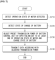
- FIG. 7 is a flowchart showing a battery management method according another an embodiment of the present invention.
- the battery control unit 510 receives the operation state of a motor detected S710.
- the operation state of the motor may be detected by a motor sensing unit provided in a vehicle.
- the motor sensing unit may transmit the detected operation state of the motor directly to the battery control unit 510, or may transmit the same to the battery control unit though a higher-level controller. control unit though a higher-level controller.
- battery control unit 510 detects the state of charge of a battery S720.
- the state of charge of the battery may be detected by a separate charge control unit 530.
- the state of charge of the battery may be transmitted directly to the battery control unit 510 from the charge control unit 530, or may be transmitted to the battery control unit 510 through a higher-level controller.
- FIG. 8B is a diagram showing the sensing cycle and transmission power of a battery when a vehicle is driven at a high speed and then at a constant speed.
- Example 1 is a battery management apparatus comprising:
- Example 3 is a battery management apparatus with the same features as example 1, wherein the operation conditions comprise the transmission power of the battery control unit, and the condition control unit adjusts preset transmission power of the battery control unit and allows the battery control unit to transmit a signal according to the adjusted transmission power.
- Example 4 is a battery management apparatus with the same features as example 1, wherein the condition control unit controls the operations condition of the battery control unit using a fuzzy function.
- Example 6 is a battery management apparatus with the same features as example 1, wherein the battery control unit receives the operation state of the motor from a motor sensing unit or a higher-level controller of a vehicle.
- Example 7 is a battery management apparatus with the same features as example 1, further comprising a charge control unit for controlling the charging of the battery, wherein the state of charge of the battery is either directly transmitted from the charge control unit to the battery control unit, or transmitted from the higher-level controller, and then transmitted from the higher-level controller to the battery control unit.
Landscapes
- Engineering & Computer Science (AREA)
- Power Engineering (AREA)
- Manufacturing & Machinery (AREA)
- Chemical & Material Sciences (AREA)
- Chemical Kinetics & Catalysis (AREA)
- Electrochemistry (AREA)
- General Chemical & Material Sciences (AREA)
- Transportation (AREA)
- Life Sciences & Earth Sciences (AREA)
- Sustainable Development (AREA)
- Sustainable Energy (AREA)
- Mechanical Engineering (AREA)
- General Physics & Mathematics (AREA)
- Physics & Mathematics (AREA)
- Microelectronics & Electronic Packaging (AREA)
- Secondary Cells (AREA)
- Electric Propulsion And Braking For Vehicles (AREA)
- Charge And Discharge Circuits For Batteries Or The Like (AREA)
Abstract
Description
- This application claims the benefit of
Korean Patent Application No. 10-2019-0111784, filed on September 9, 2019 - The present invention relates to a power-saving type apparatus and method for managing a battery, which control the sensing cycle and transmission power of a battery management system based on the state of a motor and a battery of a vehicle.
- In general, when a battery of an electric vehicle is low, but a driver cannot use a charging station, the battery may just be discharged. In the case of an energy storage system (ESS) used in such a vehicle, as the amount of current consumed by a battery management system (BMS) becomes less, the power consumption of a battery may be reduced, and as the replacement cycle of a module becomes long, the cost for replacing the module may be saved.
- In addition, an application specific integrated circuit (ASIC) inside the battery management system reads battery cell state information according to a predetermined sensing cycle, and has a problem of consuming current to receive battery cell information switched from a sleep mode even when battery consumption is not large.
- nside the battery management system reads battery cell state information according to a predetermined sensing cycle, and has a problem of consuming current to receive battery cell information switched from a sleep mode even when battery consumption is not large.
- Also, in a wireless battery management system, it is common that the wireless transmission power of a master device and a slave device, which perform wireless communication, are set to a maximum value in order to minimize data loss.
- Therefore, the efficient use of power in the wireless battery management system using the voltage of a battery cell as a power source is very important.
- Further background art is described in
JP 2019-504450 A US 2019/176642 A1 . - An aspect of the present invention is to provide a power-saving type apparatus and method for managing a battery, which actively control the sensing cycle and transmission power of a battery management system according to the state of the use of a battery, thereby minimizing the amount of battery consumption in a wireless battery management system to use power efficiently.
- According to an aspect of the present invention, there is provided a battery management apparatus including a battery control unit for receiving the operation state of a motor detected and detecting the state of charge of a battery, and a condition control unit for applying a weight to at least one of the operation state of the motor and the state of charge of the battery to adjust operation conditions of the battery control unit and allowing the battery control unit to operate on the basis of the adjusted operation conditions.
operation conditions. - The operation conditions of the battery management apparatus according to an embodiment of the present invention may include the sensing cycle of the battery, and the condition control unit may adjust a preset sensing cycle of the battery and allow the battery control unit to monitor the battery according to the adjusted sensing cycle.
- The operation conditions of the battery management apparatus according to an embodiment of the present invention may include the transmission power of the battery control unit, and the condition control unit may adjust preset transmission power of the battery control unit and allow the battery control unit to transmit a signal according to the adjusted transmission power.
- t, and the condition control unit may adjust preset transmission power of the battery control unit and allow the battery control unit to transmit a signal according to the adjusted transmission power.
- The condition control unit of the battery management apparatus according to an embodiment of the present invention may control the operations condition of the battery control unit using a fuzzy function.
- The weight of the battery management apparatus according to an embodiment of the present invention may be determined for each preset range of the operation state of the motor and the state of charge of the battery.
- The battery control unit of the battery management apparatus according to an embodiment of the present invention may receive the operation state of the motor from a motor sensing unit or a higher-level controller of a vehicle.
- The battery management apparatus according to an embodiment of the present invention may further include a charge control unit for controlling the charging of the battery, wherein the state of charge of the battery may be either directly transmitted from the charge control unit to the battery control unit, or transmitted from the higher-level controller, and then transmitted from the higher-level controller to the battery control unit.
- According to another aspect of the present invention, there is provided a battery management method including receiving the operation state of a motor detected, detecting the state of charge of a battery, and applying a weight to at least one of the operation state of the motor and the state of charge of the battery to adjust operation conditions of a battery control unit.
- The operation conditions of the battery management method according to an embodiment of the present invention may include the sensing cycle of the battery, and the adjusting of the operation conditions of the battery control unit may adjust a preset sensing cycle of the battery and allow the battery control unit to perform monitoring the battery according to the adjusted sensing cycle.
- cle of the battery, and the adjusting of the operation conditions of the battery control unit may adjust a preset sensing cycle of the battery and allow the battery control unit to perform monitoring the battery according to the adjusted sensing cycle.
- The operation conditions of the battery management method according to an embodiment of the present invention may include the transmission power of the battery control unit, and the adjusting of the operation conditions of the battery control unit may adjust preset transmission power of the battery control unit and allow the battery control unit to transmit a signal according to the adjusted transmission power.
- According to a power-saving type apparatus and method for managing a battery of the present invention, the sensing cycle and transmission power of a battery management system is actively controlled according to the state of the use of a battery, so that the amount of battery consumption is minimized in a wireless battery management system, making it possible to use power efficiently.
-
-
FIG. 1 is a configuration diagram of a battery pack including a battery management system according to an embodiment of the present invention; -
FIG. 2 is a block diagram showing a configuration of a battery management apparatus according to an embodiment of the present invention; -
FIG. 3 is a diagram showing a method for calculating a sensing cycle in a battery management apparatus according to an embodiment of the present invention; -
FIG. 4 is a flowchart showing a battery management method according to an embodiment of the present invention; -
FIG. 5 is a block diagram showing a configuration of a battery management apparatus according another an embodiment of the present invention; -
FIG. 6 is a diagram showing a method for calculating transmission power in a battery management apparatus according another an embodiment of the present invention; -
FIG. 7 is a flowchart showing a battery management method according another an embodiment of the present invention; -
FIG. 8A is a diagram showing the sensing cycle and transmission power of a battery when a vehicle is driven at a constant speed and then at a high speed; -
FIG. 8B is a diagram showing the sensing cycle and transmission power of a battery when a vehicle is driven at a high speed and then at a constant speed; and -
FIG. 9 is a block diagram showing a hardware configuration of a battery management apparatus according to an embodiment of the present invention. - Hereinafter, various embodiments of the present invention will be described in detail with reference to the accompanying drawings. In the present document, like reference numerals are used for like elements throughout the drawings, and redundant descriptors of the like elements are omitted.
- For the various embodiments of the present invention disclosed in the present document, specific structural to functional descriptions are merely illustrative of the present invention. The various embodiments of the present invention may be embodied in various forms and should not be construed as limited to the embodiments set forth herein.
- esent invention may be embodied in various forms and should not be construed as limited to the embodiments set forth herein.
- Terms such as "a first," "a second," "first," and "second" used in various embodiments may modify various components regardless of the order and/or importance thereof, and do not limited the corresponding components. For example, a first component may be referred to as a second component without departing from the scope of the present invention, and similarly, a second component may also be referred to as a first component.
also be referred to as a first component. - The terms used in this document are only used to describe specific embodiments, and may not be intended to limit the scope of other embodiments. Singular expressions may include plural expressions unless the context clearly indicates otherwise.
- All the terms used herein, including technical or scientific terms, may have the same meanings as those commonly understood by those skilled in the art of the present invention. Terms that are defined in a dictionary commonly used should be interpreted as having the same or similar meaning to the meaning in the context of the related art, and should not be interpreted as having an ideal or overly formal meaning unless explicitly defined in the present document. In some cases, even the terms defined in this document should not be interpreted as excluding embodiments of the present invention.
- s document should not be interpreted as excluding embodiments of the present invention.
-
FIG. 1 is a configuration diagram of a battery pack including a battery management system according to an embodiment of the present invention. - In a
battery module 1, a plurality ofbattery cells battery cells battery management systems battery management system battery cells - mmand from the higher-level to control connected battery cells.
- The plurality of
battery cells battery module 1. In thebattery module 1, a masterbattery management system 10 is disposed. The masterbattery management system 10 performs monitoring by measuring the temperature, voltage, or current of thebattery module 1. In addition, the masterbattery management system 10 receives monitoring information of each battery cell from the slavebattery management systems battery management systems
battery cell and transmits the same to a higher-level system, and receives a specific task performance command from the higher-level system and transmits the same to corresponding slavebattery management systems -
FIG. 2 is a block diagram showing a configuration of a battery management apparatus according to an embodiment of the present invention. - Referring to
FIG. 2 , abattery management apparatus 200 according to an embodiment of the present invention may include abattery control unit 210, a sensingcycle control unit 220, and acharge control unit 230. At this time, thebattery management apparatus 200 may correspond to both the master battery management system and the slave battery management system ofFIG. 1 . In addition, according toFIG. 2 , a condition control unit of thebattery management apparatus 200 according to an embodiment of the present invention may be represented by the sensingcycle control unit 220. - esent invention may be represented by the sensing
cycle control unit 220. - The
battery control unit 210 may receive the operation state of a motor detected, and may detect the state of charge of a battery. In this case, thebattery control unit 210 may receive the operation state of the motor directly from a motor sensing unit (not shown) which detects the operation of a motor of a vehicle, or may receive the operation state of the motor from a higher-level controller. - In addition, the
battery control unit 210 may perform monitoring of the battery, and may adjust the sensing cycle of the battery or the transmission power of a signal according to the state of the battery or the motor. - e of the battery or the transmission power of a signal according to the state of the battery or the motor.
- The sensing
cycle control unit 220 may adjust a preset sensing cycle of a battery by applying a weight to at least one of the operation state of the motor received from thebattery control unit 210 and the state of charge of the battery detected therefrom. At this time, the weight may be determined for each preset range of the operation state of the motor and the state of charge of the battery. This will be described later in detail with reference toFIG. 3 .
will be described later in detail with reference toFIG. 3 . - In addition, the sensing
cycle control unit 220 may allow thebattery control unit 210 to perform monitoring a battery according to the adjusted sensing cycle. In this case, the sensingcycle control unit 220 may use a fuzzy function to adjust the sensing cycle of the battery as to be described later. - The
charge control unit 230 may control the charging of a battery. Thecharge control unit 230 may transmit the state of charge of the battery directly to thebattery control unit 210. In addition, thecharge control unit 230 may transmit the state of charge of the battery to a higher-level controller, and then allow the same to be transmitted from the higher-level controller to thebattery control unit 210. -
ge control unit 230 may transmit the state of charge of the battery to a higher-level controller, and then allow the same to be transmitted from the higher-level controller to thebattery control unit 210. - As described above, according the battery management apparatus according to an embodiment of the present invention, the sensing cycle and transmission power of a battery management system is actively controlled according to the state of the use of a battery, so that the amount of battery consumption is minimized in a wireless battery management system, making it possible to use power efficiently.
- nimized in a wireless battery management system, making it possible to use power efficiently.
-
FIG. 3 is a diagram showing a method for calculating a sensing cycle in a battery management apparatus according to an embodiment of the present invention. - Referring to
FIG. 3 , a weight graph (a) for the load (speed) of a motor, a weight graph (b) for the SOC of a battery, and a final sensing cycle (c) obtained by combining (1) and (b) are shown. However, the graphs ofFIG. 3 are only exemplary. A weight may be calculated in various manners for each case. - For example, as shown in Graph (a) of
FIG. 3 , the speed of a motor may be classified according to a fuzzy rule into ranges of very high (120 km/h or greater), high (80 km/h to 120 km/h), normal (40 km/h to 80 km/h), low (20 km/h to 40 km/h), very low or stop (20km/h or less). - 80 km/h), low (20 km/h to 40 km/h), very low or stop (20km/h or less).
- In addition, as shown in Graph (b) of
FIG. 3 , the SOC of a battery nay be classified into ranges of very high (90% or greater), high (70% to 90%), normal (50% to 70%), low (30% to 50%), very low or stop (30% or less). Referring to (b) ofFIG. 3 , as for the SOC, if the remaining battery capacity is high, an existing sensing cycle is maintained, and if the remaining battery capacity is at an intermediate level, the weight for the sensing cycle may be reduced. If the remaining battery capacity is low, the weight for the sensing cycle may be increased to confirm the state of the battery quickly. - ight for the sensing cycle may be increased to confirm the state of the battery quickly.
- The AND of
FIG. 3 means that the weight for the load (speed) of a motor and the weight for the SOC of a battery are summed. At this time,FIG. 3 is not limited to a logical operation AND only. A logical operation OR may also be applied according to an algorithm, and various operations such as +, x, Min, and Max may be applied. - For example, when referring to
FIG. 3 , when a basic sensing cycle is 100 msec, the speed of a motor is 140 km/h, and the SOC is 90%, a final sensing cycle may be calculated as follows according to the speed of the motor and the SOC of the battery.100msec × z(140km, 90%) = 100msec × (1.0 AND 1.0) = 100msec × 1.0 = 100msec - In addition, according to the battery management apparatus according to an embodiment of the present invention, only one of the load of a motor and the SOC of a battery may be selected to adjust a sensing cycle.
-
FIG. 4 is a flowchart showing a battery management method according to an embodiment of the present invention. - Referring to
FIG. 4 , first, thebattery control unit 210 receives the operation state of a motor detected S410. At this time, the operation state of the motor may be detected by a motor sensing unit provided in a vehicle. In addition, the motor sensing unit may transmit the detected operation state of the motor directly to thebattery control unit 210, or may transmit the same to thebattery control unit 210 though a higher-level controller.
rol unit 210 though a higher-level controller. - Then,
battery control unit 210 detects the state of charge of a battery S420. In this case, the state of charge of the battery may be detected by a separatecharge control unit 230. At this time, the state of charge of the battery may be transmitted directly to thebattery control unit 210 from thecharge control unit 230, or may be transmitted to thebattery control unit 210 through a higher-level controller. - Next, a preset sensing cycle of the battery may be adjusted by applying a weight to at least one of the detected operation state of the motor and the detected state of charge of the battery S430. At this time, the sensing cycle of the battery may be adjusted using a fuzzy function. In addition, the weight for adjusting a sensing cycle may be applied to each range after dividing the operation state of the motor and the state of charge of the battery into a predetermined range.
- of the detected operation state of the motor and the detected state of charge of the battery S430. At this time, the sensing cycle of the battery may be adjusted using a fuzzy function. In addition, the weight for adjusting a sensing cycle may be applied to each range after dividing the operation state of the motor and the state of charge of the battery into a predetermined range.
- Then, the
battery control unit 210 performs monitoring of the battery according to the adjusted sensing cycle S440. As described above, according to the battery management method according to an embodiment of the present invention, the sensing cycle of a battery may be actively changed according to the state of the use of the battery, so that power may be efficiently used. - ibed above, according to the battery management method according to an embodiment of the present invention, the sensing cycle of a battery may be actively changed according to the state of the use of the battery, so that power may be efficiently used.
-
FIG. 5 is a block diagram showing a configuration of a battery management apparatus according another an embodiment of the present invention. - Referring to
FIG. 5 , abattery management apparatus 500 according to an embodiment of the present invention may include abattery control unit 510, a transmissionpower control unit 520, and acharge control unit 530. According toFIG. 5 , a condition control unit of thebattery management apparatus 200 according to an embodiment of the present invention may be represented by the transmissionpower control unit 520. - ented by the transmission
power control unit 520. - The
battery control unit 510 may receive the operation state of a motor detected, and may detect the state of charge of a battery. In this case, thebattery control unit 510 may receive the operation state of the motor directly from a motor sensing unit (not shown) which detects the operation of a motor of a vehicle, or may receive the operation state of the motor from a higher-level controller. - In addition, the
battery control unit 510 may perform monitoring of the battery, and may adjust the sensing cycle of the battery or the transmission power of a signal according to the state of the battery or the motor. - e of the battery or the transmission power of a signal according to the state of the battery or the motor.
- The transmission
power control unit 520 may adjust a preset transmission power of thebattery control unit 510 by applying a weight to at least one of the operation state of the motor received from thebattery control unit 510 and the state of charge of the battery detected therefrom. At this time, the weight may be determined for each preset range of the operation state of the motor and the state of charge of the battery. This will be described later in detail with reference toFIG. 6 . - charge of the battery. This will be described later in detail with reference to
FIG. 6 . - In addition, the transmission
power control unit 520 may allow thebattery control unit 510 to transmit a signal with transmission power. In this case, the transmissionpower control unit 520 may use a fuzzy function to adjust the transmission power of thebattery control unit 510 as to be described later. - The
charge control unit 530 may control the charging of a battery. Thecharge control unit 530 may transmit the state of charge of the battery directly to thebattery control unit 510. In addition, thecharge control unit 530 may transmit the state of charge of the battery to a higher-level controller, and then allow the same to be transmitted from the higher-level controller to thebattery control unit 510. -
charge control unit 530 may transmit the state of charge of the battery to a higher-level controller, and then allow the same to be transmitted from the higher-level controller to thebattery control unit 510. - As described above, according the battery management apparatus according to an embodiment of the present invention, the sensing cycle and transmission power of a battery management system is actively controlled according to the state of the use of a battery, so that the amount of battery consumption is minimized in a wireless battery management system, making it possible to use power efficiently.
- is minimized in a wireless battery management system, making it possible to use power efficiently.
-
FIG. 6 is a diagram showing a method for calculating transmission power in a battery management apparatus according another an embodiment of the present invention. - Referring to
FIG. 6 , a weight graph (a) for the load (speed) of a motor, a weight graph (b) for the SOC of a battery, and a final transmission power (c) obtained by combining (1) and (b) are shown. However, the graphs ofFIG. 6 are only exemplary. A weight may be calculated in various manners for each case. - For example, as shown in Graph (a) of
FIG. 6 , the speed of a motor may be classified according to a fuzzy rule into ranges of very high (120 km/h or greater), high (80 km/h to 120 km/h), normal (40 km/h to 80 km/h), low (20 km/h to 40 km/h), very low or stop (20km/h or less). - to 80 km/h), low (20 km/h to 40 km/h), very low or stop (20km/h or less).
- In addition, as shown in Graph (b) of
FIG. 6 , the SOC of a battery nay be classified into ranges of very high (90% or greater), high (70% to 90%), normal (50% to 70%), low (30% to 50%), very low or stop (30% or less). - Referring to (b) of
FIG. 6 , as for the SOC, if the remaining battery capacity is high, existing transmission power is maintained, and if the remaining battery capacity is at an intermediate level, the weight for the transmission power may be reduced. If the remaining battery capacity is low, the weight for the transmission power may be increased to confirm the state of the battery quickly.
the weight for the transmission power may be increased to confirm the state of the battery quickly. - The AND of
FIG. 6 means that the weight for the load (speed) of a motor and the weight for the SOC of a battery are summed. At this time,FIG. 6 is not limited to a logical operation AND only. A logical operation OR may also be applied according to an algorithm, and various operations such as +, x, Min, and Max may be applied. - For example, when referring to
FIG. 6 , when basic transmission power is 20 dBm, the speed of a motor is 140 km/h, and the SOC is 60%, final transmission power may be calculated as follows according to the speed of the motor and the SOC of the battery. In addition, in the following equation, AND was used as an average value (AAND B = (A+B)/2).20dBm x z(140km, 60%) = 20dBm x (1.0 AND 0) = 20dBm x 0.5 = 10dBm - In addition, according to the battery management apparatus according to an embodiment of the present invention, only one of the load of a motor and the SOC of a battery may be selected to adjust transmission power.
-
FIG. 7 is a flowchart showing a battery management method according another an embodiment of the present invention. - Referring to
FIG. 7 , first, thebattery control unit 510 receives the operation state of a motor detected S710. At this time, the operation state of the motor may be detected by a motor sensing unit provided in a vehicle. In addition, the motor sensing unit may transmit the detected operation state of the motor directly to thebattery control unit 510, or may transmit the same to the battery control unit though a higher-level controller.
control unit though a higher-level controller. - Then,
battery control unit 510 detects the state of charge of a battery S720. In this case, the state of charge of the battery may be detected by a separatecharge control unit 530. At this time, the state of charge of the battery may be transmitted directly to thebattery control unit 510 from thecharge control unit 530, or may be transmitted to thebattery control unit 510 through a higher-level controller. - Next, a preset transmission power of the battery may be adjusted by applying a weight to at least one of the detected operation state of the motor and the detected state of charge of the battery S730. At this time, the transmission power of the
battery control unit 510 may be adjusted using a fuzzy function. In addition, the weight for adjusting transmission power may be applied to each range after dividing the operation state of the motor and the state of charge of the battery into a predetermined range. - Then, the
battery control unit 510 performs monitoring of the battery according to the adjusted transmission power S740. As described above, according to the battery management method according to an embodiment of the present invention, the transmission power of thebattery control unit 510 may be actively changed according to the state of the use of the battery, so that power may be efficiently used. -
FIG. 8A is a diagram showing the sensing cycle and transmission power of a battery when a vehicle is driven at a constant speed and then at a high speed; In addition,FIG. 8B is a diagram showing the sensing cycle and transmission power of a battery when a vehicle is driven at a high speed and then at a constant speed. - n at a constant speed and then at a high speed; In addition,
FIG. 8B is a diagram showing the sensing cycle and transmission power of a battery when a vehicle is driven at a high speed and then at a constant speed. - Referring to 8A, when battery consumption increases rapidly, such as when a driver of a vehicle is driving at a constant speed and then gradually speeding up, enters an uphill road, or starts fast charging, the cycle of sensing the state of a battery becomes gradually shorter and communication is achieved with greater transmit power, so that the state of the battery may be monitored as accurately as possible.
achieved with greater transmit power, so that the state of the battery may be monitored as accurately as possible. - Referring to
FIG. 8B , when a driver of a vehicle enters a constant speed driving mode from a driving mode in which the state of a battery rapidly changes as in the above examples, the cycle of sensing the state of the battery becomes gradually longer and communication is achieved with relatively less transmission power, so that battery power may be efficiently managed without unnecessary monitoring.
oring. -
FIG. 9 is a block diagram showing a hardware configuration of a battery management apparatus according to an embodiment of the present invention. - As shown in
FIG. 9 , abattery management apparatus 900 may have a micro-controller (MCU) 910 for controlling various processing and each component, amemory 920 in which an operating system program, various programs (for example, a battery pack abnormality diagnosis program or a battery pack temperature estimation program), and the like are stored, an input/output interface 930 for providing an input interface and an output interface between a battery cell module and/or a switching unit (for example, a semiconductor switching element), and acommunication interface 940 capable of communicating with the outside (for example, a higher-level controller) through a wired/wireless communication network. As described above, a computer program according to the present invention is stored in thememory 920 and processed by themicro-controller 910, and thus, may be implemented as, for example, a module which performs each functional block illustrated inFIG. 2 . - ted as, for example, a module which performs each functional block illustrated in
FIG. 2 . - In the above, even if all the components constituting the embodiments of the present invention have been described as being combined or combined to operate as one, the present invention is not necessarily limited to these embodiments. That is, if within the scope of the present invention, all of the components maybe selectively combined and operated as one or more.
- In addition, the terms "include," "consist," or "have" as described above mean that a corresponding component may be intrinsic, unless specifically stated otherwise, and it should interpreted as including other components rather than excluding other components. All terms including technical or scientific terms have the same meanings as those commonly understood by those skilled in the art to which the present invention pertains, unless defined otherwise. Terms commonly used as those defined in a commonly used dictionary should be construed as being consistent with the context of the relevant art, and are not to be construed in an idealized or overly formal sense unless expressly defined in the present invention.
- erly formal sense unless expressly defined in the present invention.
- The above description is merely illustrative of the technical idea of the present invention, and those skilled in the art to which the present invention pertains may make various modifications and variations without departing from the essential characteristics of the present invention. Therefore, the embodiments disclosed in the present invention are not intended to limit the technical teaching of the present invention, but to explain, and the scope of the technical teaching of the present invention is not limited by these embodiments. The scope of protection of the present invention should be construed by the following claims, and all technical concepts within the scope of the present invention should be construed as being included within the scope of the rights of present invention.
- Example 1 is a battery management apparatus comprising:
- a battery control unit for receiving the operation state of a motor detected and detecting the state of charge of a battery; and
- a condition control unit for applying a weight to at least one of the operation state of the motor and the state of charge of the battery to adjust operation conditions of the battery control unit and allowing the battery control unit to operate on the basis of the adjusted operation conditions.
- Example 2 is a battery management apparatus with the same features as example 1, wherein the operation conditions comprise the sensing cycle of the battery, and the condition control unit adjusts a preset sensing cycle of the battery and allows the battery control unit to monitor the battery according to the adjusted sensing cycle.
- Example 3 is a battery management apparatus with the same features as example 1, wherein the operation conditions comprise the transmission power of the battery control unit, and the condition control unit adjusts preset transmission power of the battery control unit and allows the battery control unit to transmit a signal according to the adjusted transmission power.
- Example 4 is a battery management apparatus with the same features as example 1, wherein the condition control unit controls the operations condition of the battery control unit using a fuzzy function.
- Example 5 is a battery management apparatus with the same features as example 1, wherein the weight is determined for each preset range of the operation state of the motor and the state of charge of the battery.
- Example 6 is a battery management apparatus with the same features as example 1, wherein the battery control unit receives the operation state of the motor from a motor sensing unit or a higher-level controller of a vehicle.
- Example 7 is a battery management apparatus with the same features as example 1, further comprising a charge control unit for controlling the charging of the battery, wherein the state of charge of the battery is either directly transmitted from the charge control unit to the battery control unit, or transmitted from the higher-level controller, and then transmitted from the higher-level controller to the battery control unit.
- Example 8 is a battery management method comprising:
- receiving the operation state of a motor detected;
- detecting the state of charge of a battery; and
- applying a weight to at least one of the operation state of the motor and the state of charge of the battery to adjust operation conditions of a battery control unit.
- Example 9 is a method with the same features as example 8, wherein the operation conditions comprise the sensing cycle of the battery, and the adjusting of the operation conditions of the battery control unit is to adjust a preset sensing cycle of the battery and allow the battery control unit to monitor the battery according to the adjusted sensing cycle.
- Example 10 is a method with the same features as example 8, wherein
- the operation conditions comprise the transmission power of the battery control unit, and
- the adjusting of the operation conditions of the battery control unit is to adjust preset transmission power of the battery control unit and allow the battery control unit to transmit a signal according to the adjusted transmission power.
Claims (4)
- A wireless battery management apparatus (200, 500) comprising:a battery control unit (210, 510) configured to receive the operation state of a motor of a vehicle detected by a higher-level controller of the vehicle and detect the state of charge of a battery or receive the state of charge of the battery from a charge control unit (530); anda condition control unit (220, 520) configured to apply a weight to the operation state of the motor and the state of charge of the battery to adjust operation conditions of the battery control unit, thereby the battery control unit operates on the basis of the adjusted operation conditions,wherein the operation state of the motor is divided into preset speed ranges and the state of charge of the battery is divided into preset ranges and a weight is predetermined for each preset range;wherein:a) the operation conditions comprise the sensing cycle of the battery, and the condition control unit (220) is configured to adjust a preset sensing cycle of the battery thereby when the battery control unit monitors the battery, it monitors the battery according to the adjusted sensing cycle; orb) the operation conditions comprise the transmission power of the battery control unit, and the condition control unit (520) is configured to adjust preset transmission power of the battery control unit thereby when the battery control unit transmits a signal, it transmits the signal according to the adjusted transmission power.
- The battery management apparatus of claim 1, wherein the condition control unit controls the operation conditions of the battery control unit using a fuzzy function.
- The battery management apparatus of claim 1, further comprising the charge control unit (230, 530) configured to control the charging of the battery, wherein the state of charge of the battery is either directly transmitted from the charge control unit to the battery control unit, or transmitted to the higher-level controller, and then transmitted from the higher-level controller to the battery control unit.
- A battery management method comprising:receiving (S410, S710) the operation state of a motor detected through a higher-level controller of the vehicle;detecting (S420, S720) the state of charge of a battery; andapplying (S430, S440, S730, S740) a weight to the operation state of the motor and the state of charge of the battery and adjusting operation conditions of a battery control unit based on the applied weight;wherein:a) the operation conditions comprise the sensing cycle of the battery, and adjusting the operation conditions comprises adjusting (S430) a preset sensing cycle of the battery, and monitoring (S440) the battery according to the adjusted sensing cycle; orb) the operation conditions comprise the transmission power of the battery control unit, and adjusting the operation conditions comprises adjusting (S730) preset transmission power of the battery control unit, and transmitting (S740) a signal according to the adjusted transmission power.
Applications Claiming Priority (3)
| Application Number | Priority Date | Filing Date | Title |
|---|---|---|---|
| KR1020190111784A KR102640095B1 (en) | 2019-09-09 | 2019-09-09 | Power saving battery management apparatus and method |
| EP20864169.6A EP3950416B1 (en) | 2019-09-09 | 2020-07-23 | POWER-SAVING TYPE APPARATUS AND METHOD FOR\nMANAGING BATTERY |
| PCT/KR2020/009700 WO2021049752A1 (en) | 2019-09-09 | 2020-07-23 | Power-saving battery management apparatus and method |
Related Parent Applications (2)
| Application Number | Title | Priority Date | Filing Date |
|---|---|---|---|
| EP20864169.6A Division-Into EP3950416B1 (en) | 2019-09-09 | 2020-07-23 | POWER-SAVING TYPE APPARATUS AND METHOD FOR\nMANAGING BATTERY |
| EP20864169.6A Division EP3950416B1 (en) | 2019-09-09 | 2020-07-23 | POWER-SAVING TYPE APPARATUS AND METHOD FOR\nMANAGING BATTERY |
Publications (2)
| Publication Number | Publication Date |
|---|---|
| EP4525265A2 true EP4525265A2 (en) | 2025-03-19 |
| EP4525265A3 EP4525265A3 (en) | 2025-06-25 |
Family
ID=74865891
Family Applications (2)
| Application Number | Title | Priority Date | Filing Date |
|---|---|---|---|
| EP24221583.8A Pending EP4525265A3 (en) | 2019-09-09 | 2020-07-23 | Power-saving type apparatus and method for managing battery |
| EP20864169.6A Active EP3950416B1 (en) | 2019-09-09 | 2020-07-23 | POWER-SAVING TYPE APPARATUS AND METHOD FOR\nMANAGING BATTERY |
Family Applications After (1)
| Application Number | Title | Priority Date | Filing Date |
|---|---|---|---|
| EP20864169.6A Active EP3950416B1 (en) | 2019-09-09 | 2020-07-23 | POWER-SAVING TYPE APPARATUS AND METHOD FOR\nMANAGING BATTERY |
Country Status (9)
| Country | Link |
|---|---|
| US (1) | US12467978B2 (en) |
| EP (2) | EP4525265A3 (en) |
| JP (1) | JP7293562B2 (en) |
| KR (1) | KR102640095B1 (en) |
| CN (2) | CN118971227A (en) |
| ES (1) | ES3019557T3 (en) |
| HU (1) | HUE070579T2 (en) |
| PL (1) | PL3950416T3 (en) |
| WO (1) | WO2021049752A1 (en) |
Families Citing this family (3)
| Publication number | Priority date | Publication date | Assignee | Title |
|---|---|---|---|---|
| KR20210016795A (en) * | 2019-08-05 | 2021-02-17 | 주식회사 엘지화학 | Energy hub apparatus and energy managemnet method |
| KR20220057368A (en) * | 2020-10-29 | 2022-05-09 | 주식회사 엘지에너지솔루션 | Apparatus and method for managing battery, battery managing system |
| KR20220167117A (en) * | 2021-06-11 | 2022-12-20 | 주식회사 엘지에너지솔루션 | Apparatus and method for preventing over discharge |
Citations (2)
| Publication number | Priority date | Publication date | Assignee | Title |
|---|---|---|---|---|
| JP2019504450A (en) | 2016-08-12 | 2019-02-14 | エルジー・ケム・リミテッド | Temperature monitoring apparatus and method for battery pack |
| US20190176642A1 (en) | 2017-12-11 | 2019-06-13 | Moustapha Diab | Techniques for adjusting wakeup time of an electrified vehicle for low voltage battery conditioning |
Family Cites Families (40)
| Publication number | Priority date | Publication date | Assignee | Title |
|---|---|---|---|---|
| US5781013A (en) * | 1994-10-26 | 1998-07-14 | Fuji Jukogyo Kabushiki Kaisha | Battery management system for electric vehicle |
| US5869951A (en) * | 1994-10-26 | 1999-02-09 | Fuji Jukogyo Kabushiki Kaisha | Battery management system for electric vehicle |
| JPH0956184A (en) * | 1995-08-10 | 1997-02-25 | Denso Corp | Motor control device for electric vehicle driving |
| US5917305A (en) * | 1997-12-11 | 1999-06-29 | Compaq Computer Corporation | Battery control architecture with standardized language |
| JP2000134705A (en) | 1998-10-23 | 2000-05-12 | Honda Motor Co Ltd | Battery level detection method |
| JP4023030B2 (en) | 1999-05-14 | 2007-12-19 | トヨタ自動車株式会社 | POWER OUTPUT DEVICE, HYBRID VEHICLE HAVING SAME, AND METHOD FOR CONTROLLING POWER OUTPUT DEVICE |
| JP3334753B2 (en) | 1999-06-15 | 2002-10-15 | 日本電気株式会社 | Mobile terminal, mobile communication system, and method for suppressing power consumption of mobile terminal |
| JP2007230398A (en) | 2006-03-01 | 2007-09-13 | Fujitsu Ten Ltd | Device and method of monitoring battery |
| EP1892536B1 (en) | 2006-08-22 | 2012-04-11 | Delphi Technologies, Inc. | Battery monitoring system |
| KR100906907B1 (en) | 2006-10-10 | 2009-07-08 | 현대자동차주식회사 | Car battery management system |
| KR100839381B1 (en) | 2006-11-01 | 2008-06-20 | 삼성에스디아이 주식회사 | Battery management system and its driving method |
| US20080156553A1 (en) * | 2006-12-20 | 2008-07-03 | Reinier Hoogenraad | Advanced hybrid golf car |
| JP5288720B2 (en) | 2007-04-06 | 2013-09-11 | 中国電力株式会社 | Tree diameter measuring instrument |
| JP4596185B2 (en) | 2007-08-29 | 2010-12-08 | 株式会社デンソー | Voltage control device for vehicle |
| US20100056325A1 (en) * | 2008-08-29 | 2010-03-04 | Paccar Inc | Automatic throttle response for a hybrid vehicle |
| JP5442729B2 (en) | 2009-06-12 | 2014-03-12 | コンビ株式会社 | stroller |
| WO2012086061A1 (en) * | 2010-12-24 | 2012-06-28 | トヨタ自動車株式会社 | Vehicle and vehicle control method |
| US20130311028A1 (en) | 2011-02-09 | 2013-11-21 | Suzuki Motor Corporation | Driving source control device for hybrid motor vehicle and driving source control method for hybrid motor vehicle and hybrid motor vehicle |
| KR20140036039A (en) | 2011-09-07 | 2014-03-24 | 혼다 기켄 고교 가부시키가이샤 | Vehicle battery control device |
| JP2013140055A (en) | 2011-12-29 | 2013-07-18 | Toyota Central R&D Labs Inc | Battery monitoring system |
| JP2014033604A (en) | 2012-07-13 | 2014-02-20 | Sanyo Electric Co Ltd | Charge/discharge state equalization method for battery system, charge/discharge state change method for battery system, and battery system |
| KR101564365B1 (en) | 2012-11-12 | 2015-10-29 | 주식회사 엘지화학 | System and method for balancing of battery using wireless communications |
| GB2510821B (en) * | 2013-02-13 | 2015-08-19 | Jaguar Land Rover Ltd | Charging Method |
| KR101535627B1 (en) * | 2013-11-11 | 2015-07-09 | 현대오트론 주식회사 | Car battery monitoring system |
| FR3013514B1 (en) | 2013-11-19 | 2016-09-09 | Commissariat Energie Atomique | DEVICE AND METHOD FOR RECHARGING ELECTRIC OR HYBRID VEHICLES |
| JP6429166B2 (en) * | 2014-09-25 | 2018-11-28 | 株式会社国際電気通信基礎技術研究所 | Wireless power transmission system |
| KR101775964B1 (en) * | 2015-12-01 | 2017-09-07 | 현대오트론 주식회사 | Apparatus and method for preventing over-discharge of battery |
| KR20170081933A (en) | 2016-01-05 | 2017-07-13 | 현대자동차주식회사 | Vehicle And Control Method Thereof |
| KR101936995B1 (en) | 2016-11-25 | 2019-01-10 | 현대자동차주식회사 | Method and system for controlling motors |
| KR102015168B1 (en) | 2017-01-26 | 2019-08-27 | 한국과학기술원 | Method and apparatus for estimating remaining range of electric vehicle |
| JP6790931B2 (en) * | 2017-03-14 | 2020-11-25 | 株式会社デンソー | Battery state estimator |
| KR102420198B1 (en) | 2017-04-03 | 2022-07-13 | 삼성전자주식회사 | Electronic device and method for controlling transmit power in device-to-device communication |
| CN107139762A (en) | 2017-06-05 | 2017-09-08 | 吉林大学 | A kind of electric automobile optimization charge control method and its system |
| KR102137759B1 (en) * | 2017-07-06 | 2020-07-24 | 주식회사 엘지화학 | Apparatus for managing battery pack |
| KR102157882B1 (en) | 2017-07-19 | 2020-09-18 | 주식회사 엘지화학 | Wireless battery manamement system and a battery pack including the same |
| KR102044276B1 (en) * | 2017-12-29 | 2019-11-12 | 주식회사 경신 | Apparatus and method for controlling charging of a dual battery system |
| JP2019129542A (en) * | 2018-01-19 | 2019-08-01 | 三菱自動車工業株式会社 | Electric vehicle charging control device |
| KR101967464B1 (en) | 2018-04-12 | 2019-04-09 | 현대오트론 주식회사 | Method for preventing battery discharge and electronic control unit using the same |
| CN108710084A (en) * | 2018-06-01 | 2018-10-26 | 王泽霖 | A kind of monitoring of electric car power supply and energy management system |
| CN108899975A (en) * | 2018-08-10 | 2018-11-27 | 肇庆市高新区甜慕新能源技术有限公司 | A kind of battery system |
-
2019
- 2019-09-09 KR KR1020190111784A patent/KR102640095B1/en active Active
-
2020
- 2020-07-23 WO PCT/KR2020/009700 patent/WO2021049752A1/en not_active Ceased
- 2020-07-23 HU HUE20864169A patent/HUE070579T2/en unknown
- 2020-07-23 US US17/603,129 patent/US12467978B2/en active Active
- 2020-07-23 EP EP24221583.8A patent/EP4525265A3/en active Pending
- 2020-07-23 ES ES20864169T patent/ES3019557T3/en active Active
- 2020-07-23 CN CN202410969361.0A patent/CN118971227A/en active Pending
- 2020-07-23 EP EP20864169.6A patent/EP3950416B1/en active Active
- 2020-07-23 PL PL20864169.6T patent/PL3950416T3/en unknown
- 2020-07-23 CN CN202080031151.7A patent/CN113767542B/en active Active
- 2020-07-23 JP JP2021549546A patent/JP7293562B2/en active Active
Patent Citations (2)
| Publication number | Priority date | Publication date | Assignee | Title |
|---|---|---|---|---|
| JP2019504450A (en) | 2016-08-12 | 2019-02-14 | エルジー・ケム・リミテッド | Temperature monitoring apparatus and method for battery pack |
| US20190176642A1 (en) | 2017-12-11 | 2019-06-13 | Moustapha Diab | Techniques for adjusting wakeup time of an electrified vehicle for low voltage battery conditioning |
Also Published As
| Publication number | Publication date |
|---|---|
| US20220187379A1 (en) | 2022-06-16 |
| WO2021049752A1 (en) | 2021-03-18 |
| EP3950416B1 (en) | 2025-03-05 |
| CN118971227A (en) | 2024-11-15 |
| KR20210030563A (en) | 2021-03-18 |
| EP3950416A4 (en) | 2022-12-07 |
| KR102640095B1 (en) | 2024-02-26 |
| US12467978B2 (en) | 2025-11-11 |
| CN113767542A (en) | 2021-12-07 |
| ES3019557T3 (en) | 2025-05-20 |
| PL3950416T3 (en) | 2025-04-28 |
| JP2022522139A (en) | 2022-04-14 |
| HUE070579T2 (en) | 2025-06-28 |
| CN113767542B (en) | 2024-08-13 |
| EP4525265A3 (en) | 2025-06-25 |
| EP3950416A1 (en) | 2022-02-09 |
| JP7293562B2 (en) | 2023-06-20 |
Similar Documents
| Publication | Publication Date | Title |
|---|---|---|
| US10991994B2 (en) | Temperature monitoring apparatus and method for battery pack | |
| CN109906168B (en) | Management device for battery pack | |
| EP3444921B1 (en) | Charging control apparatus and method capable of energy saving and quick cell balancing | |
| EP3950416B1 (en) | POWER-SAVING TYPE APPARATUS AND METHOD FOR\nMANAGING BATTERY | |
| EP4236236B1 (en) | System and method for managing battery | |
| US7917276B2 (en) | Vehicle-use power supply apparatus | |
| EP3544144A1 (en) | Solar battery system and conrol method thereof | |
| US20080024007A1 (en) | Multiple load hybrid power supply | |
| EP2530776A2 (en) | Voltage monitoring system and voltage monitoring module | |
| US8878491B2 (en) | Battery voltage monitoring apparatus | |
| US20140079963A1 (en) | Battery System Control Method | |
| US9362760B2 (en) | Battery having a plurality of battery cells and method for regulating a battery voltage of a battery using switch-on probabilities of the battery cells | |
| US20140097787A1 (en) | Active battery management system for a battery pack | |
| KR20140116783A (en) | Energy storage system controller | |
| TW201443794A (en) | Large electric vehicle power supply structure and battery box rotation control method thereof | |
| JP7107487B2 (en) | Battery management device and method | |
| US12555841B2 (en) | System and method for cooling battery modules included in energy storage system (ESS) | |
| US20150295424A1 (en) | Equalization Device | |
| EP3675312B1 (en) | Battery balancing system, vehicle, battery balancing method, and storage medium | |
| KR102899571B1 (en) | Appratus and method for monitoring battery | |
| KR20230174322A (en) | Battery cell controller providing function of blocking internal leakage current | |
| KR20200032415A (en) | Ic id auto increment communication method with daisy chain connection structure and ic communication device performing the same | |
| CN119590284A (en) | Electric vehicle battery system control strategy combined with active cell temperature balancing | |
| CN119590285A (en) | Electric vehicle battery system control strategy combined with thermal management |
Legal Events
| Date | Code | Title | Description |
|---|---|---|---|
| PUAI | Public reference made under article 153(3) epc to a published international application that has entered the european phase |
Free format text: ORIGINAL CODE: 0009012 |
|
| STAA | Information on the status of an ep patent application or granted ep patent |
Free format text: STATUS: REQUEST FOR EXAMINATION WAS MADE |
|
| 17P | Request for examination filed |
Effective date: 20241219 |
|
| AC | Divisional application: reference to earlier application |
Ref document number: 3950416 Country of ref document: EP Kind code of ref document: P |
|
| AK | Designated contracting states |
Kind code of ref document: A2 Designated state(s): AL AT BE BG CH CY CZ DE DK EE ES FI FR GB GR HR HU IE IS IT LI LT LU LV MC MK MT NL NO PL PT RO RS SE SI SK SM TR |
|
| REG | Reference to a national code |
Ref country code: DE Ref legal event code: R079 Free format text: PREVIOUS MAIN CLASS: H02J0007140000 Ipc: B60L0058120000 |
|
| PUAL | Search report despatched |
Free format text: ORIGINAL CODE: 0009013 |
|
| AK | Designated contracting states |
Kind code of ref document: A3 Designated state(s): AL AT BE BG CH CY CZ DE DK EE ES FI FR GB GR HR HU IE IS IT LI LT LU LV MC MK MT NL NO PL PT RO RS SE SI SK SM TR |
|
| RIC1 | Information provided on ipc code assigned before grant |
Ipc: H02J 7/14 20060101ALI20250519BHEP Ipc: H02J 7/00 20060101ALI20250519BHEP Ipc: G01R 31/34 20200101ALI20250519BHEP Ipc: G01R 31/382 20190101ALI20250519BHEP Ipc: H01M 10/48 20060101ALI20250519BHEP Ipc: H01M 10/42 20060101ALI20250519BHEP Ipc: B60L 3/12 20060101ALI20250519BHEP Ipc: B60L 58/12 20190101AFI20250519BHEP |