EP4525229A1 - Solid insulated busbar - Google Patents
Solid insulated busbar Download PDFInfo
- Publication number
- EP4525229A1 EP4525229A1 EP23803187.6A EP23803187A EP4525229A1 EP 4525229 A1 EP4525229 A1 EP 4525229A1 EP 23803187 A EP23803187 A EP 23803187A EP 4525229 A1 EP4525229 A1 EP 4525229A1
- Authority
- EP
- European Patent Office
- Prior art keywords
- insulation
- busbar
- adapter
- solid insulated
- lid portion
- Prior art date
- Legal status (The legal status is an assumption and is not a legal conclusion. Google has not performed a legal analysis and makes no representation as to the accuracy of the status listed.)
- Pending
Links
Images





Classifications
-
- H—ELECTRICITY
- H02—GENERATION; CONVERSION OR DISTRIBUTION OF ELECTRIC POWER
- H02B—BOARDS, SUBSTATIONS OR SWITCHING ARRANGEMENTS FOR THE SUPPLY OR DISTRIBUTION OF ELECTRIC POWER
- H02B13/00—Arrangement of switchgear in which switches are enclosed in, or structurally associated with, a casing, e.g. cubicle
- H02B13/005—Electrical connection between switchgear cells
-
- H—ELECTRICITY
- H01—ELECTRIC ELEMENTS
- H01R—ELECTRICALLY-CONDUCTIVE CONNECTIONS; STRUCTURAL ASSOCIATIONS OF A PLURALITY OF MUTUALLY-INSULATED ELECTRICAL CONNECTING ELEMENTS; COUPLING DEVICES; CURRENT COLLECTORS
- H01R13/00—Details of coupling devices of the kinds covered by groups H01R12/70 or H01R24/00 - H01R33/00
- H01R13/46—Bases; Cases
- H01R13/53—Bases or cases for heavy duty; Bases or cases for high voltage with means for preventing corona or arcing
-
- H—ELECTRICITY
- H02—GENERATION; CONVERSION OR DISTRIBUTION OF ELECTRIC POWER
- H02B—BOARDS, SUBSTATIONS OR SWITCHING ARRANGEMENTS FOR THE SUPPLY OR DISTRIBUTION OF ELECTRIC POWER
- H02B1/00—Frameworks, boards, panels, desks, casings; Details of substations or switching arrangements
- H02B1/16—Earthing arrangements
Definitions
- the present disclosure relates to a solid insulated busbar.
- Such a gas-insulated switchgear is configured such that one or a plurality of devices are stored in one compartment (counted as one panel) and a plurality of such compartments are arranged and connected by a busbar.
- the solid insulated busbar is composed of a busbar connecting main circuits of adjacent boards, and an insulation adapter provided so as to cover a connection part between each board and the busbar.
- the insulation adapter has, around the entire outer periphery, a grounded shield layer formed by a conductive paint or the like.
- a conductive rubber cap is attached at an upper part of a conical insulation plug after attachment work, in order to block an electric field, ground leakage current, and prevent entry of a foreign material.
- the present disclosure has been made to solve the above problem, and an object of the present disclosure is to prevent deterioration through a long period from influencing an electric field blocking function, an electric charge grounding function, and a foreign material entry preventing function.
- a solid insulated busbar includes: a busbar having a busbar conductor and an insulation layer coating a periphery of the busbar conductor; an insulation adapter supporting the busbar; an insulation plug provided on a vertically upper side of the insulation adapter and connected to the insulation adapter; and a bushing provided on a vertically lower side of the insulation adapter in order to connect the insulation adapter and outside.
- the insulation plug includes an upper metal insert and a conductive lid portion, and the lid portion is in contact with a grounded shield layer at a surface of the insulation adapter.
- the solid insulated busbar according to the present disclosure can prevent deterioration of an electric field blocking function, an electric charge grounding function, and a foreign material entry preventing function through a long period.
- the insulation plug 4A is formed of the insulation layer 4a, the upper metal insert 4b, the lower metal insert 4c, and a conductive cap 10.
- the conductive cap 10 is made of conductive rubber or conductive plastic in view of ease of attachment to the insulation adapter 1.
- the fixation conductors 6 are made of metal having high conductivity, such as copper and aluminum, in order to ensure conduction between the central conductor 3a of the bushing 3 and the busbar conductors 2a of the two busbars 2.
- the upper metal insert 4b and the lid portion 4d of the insulation plug 4 have an integrated structure and are made of a conductive metal material such as copper or aluminum.
- the upper metal insert 4b and the lid portion 4d may be separated from each other and the lid portion 4d may be made of a non-metal conductive material, whereby the same effects can be provided.
- a solid insulated busbar of embodiment 2 has a bolt portion added at an upper part of the insulation plug so as to enable management of a tightening force to the insulation adapter, for the purpose of improving assemblability.
- the insulation plug 4B is formed of the insulation layer 4a, the upper metal insert 4b, the lower metal insert 4c, the lid portion 4d, and a bolt portion 4e.
- the bolt portion 4e is added at an upper part of the insulation plug 4, that is, an upper part of the lid portion 4d, and may be a hexagonal bolt, for example.
- the insulation layer 4a has a conical shape tapered toward the distal end.
- the lower metal insert 4c has an internal thread and is screwed with the stud bolt 5, whereby the insulation plug 4B is fixed while having a certain surface pressure.
- the bolt portion 4e is added at an upper part of the insulation plug 4B, as compared to the solid insulated busbar 100 of embodiment 1.
- a force of tightening the insulation plug 4B to the insulation adapter 1 can be managed.
- the solid insulated busbar 200 of embodiment 2 enables improvement in assemblability as compared to the solid insulated busbar 100 of embodiment 1.
- the solid insulated busbar of embodiment 2 has a bolt portion added at an upper part of the insulation plug so as to enable management of a tightening force to the insulation adapter, for the purpose of improving assemblability.
- the solid insulated busbar of embodiment 2 can prevent the electric field blocking function, the electric charge grounding function, and the foreign material entry preventing function from being deteriorated through a long period. Further, the solid insulated busbar of embodiment 2 enables management of a tightening force to the insulation adapter, whereby assemblability can be improved.
- a solid insulated busbar of embodiment 3 has such a structure that the lid portion is attached by a fixation bolt after the insulation layer, the upper metal insert, and the lower metal insert of the insulation plug are inserted into the insulation adapter.
- FIG. 5A is a sectional view showing a structure of the solid insulated busbar
- FIG. 5B is a sectional view showing a part of FIG. 5A .
- the insulation plug 4C is formed of the insulation layer 4a, an upper metal insert 4f, the lower metal insert 4c, a lid portion 4g, and a fixation bolt 4h.
- FIG. 5B shows a manner for fixing the lid portion 4g to the upper metal insert 4f using the fixation bolt 4h.
- the upper metal insert 4f has an internal thread to be fitted with a screw part of the fixation bolt 4h.
- the bushing 3 and the insulation plug 4C are screwed into the vertical-direction conical portions of the insulation adapter 1 with grease therebetween and are connected to the insulation adapter 1 while having certain surface pressures.
- the grounded shield layer 1b is formed by applying a conductive paint on a surface of the insulation adapter 1 after the insulation adapter 1 is molded.
- a conductive paint on a surface of the insulation layer 1a of the insulation adapter 1 and a surface of the insulation plug 4 using a spray or the like after the insulation plug 4 is inserted into the insulation adapter 1 can be formed over the entire surfaces of the insulation adapter 1 and the insulation plug 4.
- the solid insulated busbar of embodiment 4 has such a structure that the lid portion is formed after the insulation layer, the upper metal insert, and the lower metal insert of the insulation plug are inserted into the insulation adapter.
Landscapes
- Engineering & Computer Science (AREA)
- Power Engineering (AREA)
- Installation Of Bus-Bars (AREA)
- Gas-Insulated Switchgears (AREA)
- Patch Boards (AREA)
Abstract
Description
- The present disclosure relates to a solid insulated busbar.
- In a gas-insulated switchgear, owing to a high insulation property of SF6 gas, devices can be made compact, contributing to space saving in an electrical room. In the gas-insulated switchgear, a main circuit part to which high voltage is applied is stored in a closed container, and SF6 gas having a high insulation property is sealed in the closed container, whereby main circuit devices are arranged in a compact form. In recent years, there have been cases where environmentally friendly gas, for example, dry air, is sealed as alternative gas, instead of SF6 gas.
- Such a gas-insulated switchgear is configured such that one or a plurality of devices are stored in one compartment (counted as one panel) and a plurality of such compartments are arranged and connected by a busbar.
- Regarding a busbar part, a gas busbar style is generally used in installation of the gas-insulated switchgear, adjacent busbar tanks are connected to each other, to connect busbar conductors in the busbar tanks. In recent years, in some gas-insulated switchgears, a solid insulated busbar is used, thereby eliminating gas processing work on site in installment of a gas-insulated switchgear (for example, Patent Document 1).
- The solid insulated busbar is composed of a busbar connecting main circuits of adjacent boards, and an insulation adapter provided so as to cover a connection part between each board and the busbar. The insulation adapter has, around the entire outer periphery, a grounded shield layer formed by a conductive paint or the like. To the insulation adapter, a conductive rubber cap is attached at an upper part of a conical insulation plug after attachment work, in order to block an electric field, ground leakage current, and prevent entry of a foreign material.
- Patent Document 1:
Japanese Laid-Open Patent Publication No. 2016-92883 - In the solid insulated busbar of
Patent Document 1, since the conductive rubber cap is used, a crack occurs due to deterioration through long-term usage and thus a surface pressure is reduced, so that leakage current might fail to be grounded. - The present disclosure has been made to solve the above problem, and an object of the present disclosure is to prevent deterioration through a long period from influencing an electric field blocking function, an electric charge grounding function, and a foreign material entry preventing function.
- A solid insulated busbar according to the present disclosure includes: a busbar having a busbar conductor and an insulation layer coating a periphery of the busbar conductor; an insulation adapter supporting the busbar; an insulation plug provided on a vertically upper side of the insulation adapter and connected to the insulation adapter; and a bushing provided on a vertically lower side of the insulation adapter in order to connect the insulation adapter and outside. The insulation plug includes an upper metal insert and a conductive lid portion, and the lid portion is in contact with a grounded shield layer at a surface of the insulation adapter.
- The solid insulated busbar according to the present disclosure can prevent deterioration of an electric field blocking function, an electric charge grounding function, and a foreign material entry preventing function through a long period.
-
- [
FIG. 1] FIG. 1 is a sectional view showing a structure of a solid insulated busbar according toembodiment 1. - [
FIG. 2] FIG. 2 is a sectional view showing a structure of a solid insulated busbar in a comparative example. - [
FIG. 3] FIG. 3 is a sectional view showing another structure of the solid insulated busbar according toembodiment 1. - [
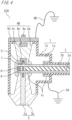
FIG. 4] FIG. 4 is a sectional view showing a structure of a solid insulated busbar according toembodiment 2. - [
FIG. 5] FIG. 5A is a sectional view showing a structure of a solid insulated busbar according toembodiment 3.FIG. 5B is a detailed view showing a part ofFIG. 5A . - [
FIG. 6] FIG. 6 is a sectional view showing a structure of a solid insulated busbar according toembodiment 4. -
Embodiment 1 relates to a solid insulated busbar including a busbar having a busbar conductor and an insulation layer coating a periphery of the busbar conductor; an insulation adapter supporting the busbar; an insulation plug provided on a vertically upper side of the insulation adapter and connected to the insulation adapter; and a bushing provided on a vertically lower side of the insulation adapter in order to connect the insulation adapter and outside, wherein the insulation plug includes a lid portion integrated with an upper metal insert buried in the insulation plug, and the lid portion is in contact with a grounded shield layer at a surface of the insulation adapter. - Hereinafter, the solid insulated busbar according to
embodiment 1 will be described with reference toFIG. 1 which is a sectional view showing a structure of the solid insulated busbar,FIG. 2 which is a sectional view showing a structure in a comparative example, andFIG. 3 which is a sectional view showing another structure. - In the drawings, the same or corresponding parts are denoted by the same reference characters and the same description will not repeatedly be given for such parts.
- The entire configuration of a solid insulated
busbar 100 ofembodiment 1 will be described with reference toFIG. 1 . - The solid insulated
busbar 100 ofembodiment 1 includes aninsulation adapter 1, abusbar 2, abushing 3, and aninsulation plug 4, as main components. - First, the overall function of the solid insulated
busbar 100 and relationships between the main components will be described. In the description of the overall function, reference characters of components other than the main components are omitted for simplification. - The solid insulated
busbar 100 includes thebusbar 2 connecting main circuits of adjacent boards present outside, and theinsulation adapter 1 detachably provided so as to cover a connection part between thebusbar 2 and each board. Theinsulation adapter 1 has, around the entire outer periphery, a grounded shield layer formed by a conductive paint or the like. - The
insulation adapter 1 has, on the vertically upper side, a conical portion for facilitating connection between the board main circuit and thebusbar 2, and after the board main circuit and thebusbar 2 are connected, theinsulation plug 4 is inserted to close the cone hole. - The
insulation plug 4 is a conical insulating body to be inserted into theinsulation adapter 1, and is formed of an insulation layer such as epoxy resin and a metal insert such as copper or aluminum buried in the insulation layer. - For the
insulation adapter 1, a lid portion of theinsulation plug 4 serves to block an electric field, ground circulation current, and prevent entry of a foreign material, after connection work for the board main circuit and thebusbar 2. - In the solid insulated
busbar 100, since high voltage is applied to theinsulation adapter 1 and a conductor coated with an insulating material and connecting theinsulation adapter 1, an electric charge is induced from the high-voltage conductor to each insulating material surface. Therefore, it is necessary to ground theinsulation adapter 1 and each insulating material surface. - Next, the function, the detailed configuration, and the material of each main component of the solid insulated
busbar 100 will be described. - The
insulation adapter 1 includes aninsulation layer 1a, agrounded shield layer 1b, and aconductive layer 1c. - The
insulation layer 1a is formed of an insulating material that is elastic and comparatively soft, such as silicone rubber or ethylene propylene rubber, and insulates charged parts (busbar conductor 2a andcentral conductor 3a) from outside. - The
grounded shield layer 1b blocks an electric field generated from the charged parts, and theconductive layer 1c relaxes the electric field of the charged parts. - The
insulation adapter 1 has a T-shaped structure having conical portions in the vertical direction and a cylindrical portion in a horizontal direction crossing the conical portions. - The
busbar 2 is formed of abusbar conductor 2a and aninsulation layer 2b. - In the
busbar 2, a periphery of thebusbar conductor 2a connecting the board main circuits is coated with theinsulation layer 2b such as silicone rubber or epoxy resin. - The
bushing 3 provided on a vertically lower side of theinsulation adapter 1 is formed of acentral conductor 3a and aninsulation layer 3b. - The
bushing 3 is, for example, a busbar connection bushing of a gas-insulated switchgear and has therein thecentral conductor 3a connected to the board main circuit, and a periphery thereof is coated with theinsulation layer 3b such as epoxy resin. Theinsulation layer 3b has a conical shape tapered toward the distal end. Thebushing 3 is fixed to a tank (not shown) of the gas-insulated switchgear by a bolt. - Here, connection of the
insulation adapter 1, thebusbar conductor 2a of thebusbar 2, and thecentral conductor 3a of thebushing 3 will be described. - The
central conductor 3a of thebushing 3 has an internal thread to be fitted with astud bolt 5, and thestud bolt 5 is screwed into thecentral conductor 3a of thebushing 3, whereby thestud bolt 5 is fixed. In a state in whichfixation conductors 6 are put in theconductive layer 1c inside theinsulation adapter 1, theinsulation adapter 1 is fitted to thestud bolt 5 and thebushing 3 from above in the vertical direction. An end of thebusbar 2 is inserted into the horizontal-direction cylindrical portion of theinsulation adapter 1, and thebusbar conductor 2a is clamped between thefixation conductors 6 and then tightened by thestud bolt 5 and anut 7, whereby theinsulation adapter 1 and thebusbar 2 are fixed. - The
fixation conductors 6 are made of metal having high conductivity, such as copper or aluminum, in order to ensure conduction between thebusbar conductor 2a of thebusbar 2 and thecentral conductor 3a of thebushing 3. In addition, asupport conductor 8 is used so that thefixation conductors 6 and thebusbar conductor 2a surface-to-surface contact with each other when tightened. - The
insulation plug 4 is formed of aninsulation layer 4a, anupper metal insert 4b, alower metal insert 4c, and alid portion 4d. A part on the upper side of theupper metal insert 4b is thelid portion 4d, and theupper metal insert 4b and thelid portion 4d have an integrated structure. - The
insulation plug 4 is formed such that theupper metal insert 4b and thelower metal insert 4c such as copper or aluminum are buried in theinsulation layer 4a such as epoxy resin. - The
insulation layer 4a has a conical shape tapered toward the distal end. Thelower metal insert 4c has an internal thread and is screwed with thestud bolt 5, whereby theinsulation plug 4 is fixed while having a certain surface pressure. - The
bushing 3 and theinsulation plug 4 are screwed into the vertical-direction conical portions of theinsulation adapter 1 with grease therebetween and are connected to theinsulation adapter 1 while having certain surface pressures. - In the solid
insulated busbar 100 ofembodiment 1, a part on the upper side of theupper metal insert 4b buried in theinsulation plug 4 is formed in such a shape that covers theinsulation layer 4a and contacts with the groundedshield layer 1b at a surface of theinsulation adapter 1 while ensuring a sufficient conduction area therewith, for example, a disk shape. The disk-shaped part is thelid portion 4d. - That is, the
conductive lid portion 4d closing the upper opening of theinsulation adapter 1 is integrated with theupper metal insert 4b. - In the solid
insulated busbar 100 ofembodiment 1, thelid portion 4d and the groundedshield layer 1b contact with each other while ensuring conduction therebetween. Therefore, an electric charge at the surface of the solidinsulated busbar 100 can flow to the ground if only one of aground wire 9A (connected to the groundedshield layer 1b) or aground wire 9B (connected to thelid portion 4d) is provided. - Next, for clarifying the feature of the solid
insulated busbar 100 ofembodiment 1, a solidinsulated busbar 100A in a comparative example will be described with reference toFIG. 2 . The solid insulated busbar and the insulation plug are respectively denoted by 100A and 4A, for the purpose of discriminating from the solidinsulated busbar 100. - The solid
insulated busbar 100A inFIG. 2 and the solidinsulated busbar 100 ofembodiment 1 are different in the structure of theinsulation plug 4A. - The
insulation plug 4A is formed of theinsulation layer 4a, theupper metal insert 4b, thelower metal insert 4c, and aconductive cap 10. - The
conductive cap 10 is attached to theinsulation adapter 1, for the purpose of blocking an electric field, grounding circulation current, and preventing entry of a foreign material, after connection work for a board main circuit and thebusbar 2. - The
conductive cap 10 and theinsulation adapter 1 are structured such that the inner diameter of theconductive cap 10 is smaller than the outer diameter of theinsulation adapter 1 and theconductive cap 10 is put over theinsulation adapter 1 so as to produce a surface pressure between theinsulation adapter 1 and theconductive cap 10, thus ensuring contact therebetween. - In many cases, the
conductive cap 10 is made of conductive rubber or conductive plastic in view of ease of attachment to theinsulation adapter 1. - However, using a rubber or plastic material as described above has a problem that the material is deteriorated due to temperature/humidity variation in the environment and undergoes creep deformation due to continuous application of the surface pressure through a long period, so that the surface pressure is reduced. If the surface pressure is reduced, contact between the
conductive cap 10 and theinsulation adapter 1 becomes unstable and theconductive cap 10 of theinsulation plug 4 comes into an electrically floating state, so that an electric charge at the surface of theconductive cap 10 might not be able to flow to the ground. - In the solid
insulated busbar 100 ofembodiment 1, thelid portion 4d of theinsulation plug 4 is made of a conductive metal material such as copper or aluminum, and closely contacts with the groundedshield layer 1b at a surface of theinsulation adapter 1. Since thelid portion 4d is made of a conductive metal material, the electric charge grounding function for the surface of an insulating material and the foreign material entry preventing function can be ensured. Thus, the electric field blocking function, the electric charge grounding function for an insulating material surface, and the foreign material entry preventing function can be prevented from being deteriorated through a long period. - Next, a structure of a solid insulated busbar in a case where the
busbars 2 are connected to theinsulation adapter 1 from both of the left and right sides, will be described with reference toFIG. 3 . The solid insulated busbar is denoted by 101, for the purpose of discriminating from the solidinsulated busbar 100. - As shown in
FIG. 3 , in a case where thebusbar 2 is connected from both of the left and right sides of theinsulation adapter 1, insertion parts for thebusbars 2 are provided on both of the left and right sides, so that the entire shape becomes a cross shape. - The
central conductor 3a of thebushing 3 has an internal thread to be fitted with thestud bolt 5, and thestud bolt 5 is screwed into thecentral conductor 3a of thebushing 3, whereby thestud bolt 5 is fixed. In a state in which thefixation conductors 6 are put in theconductive layer 1c inside theinsulation adapter 1, theinsulation adapter 1 is fitted to thestud bolt 5 and thebushing 3 from above in the vertical direction. Ends of thebusbars 2 are inserted into the horizontal-direction cylindrical portions on both of the left and right sides of theinsulation adapter 1, and thebusbar conductors 2a are clamped between thefixation conductors 6 and tightened by thestud bolt 5 and thenut 7, whereby theinsulation adapter 1 and thebusbars 2 are fixed. - The
fixation conductors 6 are made of metal having high conductivity, such as copper and aluminum, in order to ensure conduction between thecentral conductor 3a of thebushing 3 and thebusbar conductors 2a of the twobusbars 2. - In the solid
insulated busbar 100 ofembodiment 1, theupper metal insert 4b and thelid portion 4d of theinsulation plug 4 have an integrated structure and are made of a conductive metal material such as copper or aluminum. However, theupper metal insert 4b and thelid portion 4d may be separated from each other and thelid portion 4d may be made of a non-metal conductive material, whereby the same effects can be provided. - That is, the
insulation plug 4 may include theupper metal insert 4b buried in theinsulation plug 4, and theconductive lid portion 4d, and thelid portion 4d may be in contact with the groundedshield layer 1b at a surface of theinsulation adapter 1. - As described above, the solid insulated busbar of
embodiment 1 includes a busbar having a busbar conductor and an insulation layer coating a periphery of the busbar conductor; an insulation adapter supporting the busbar; an insulation plug provided on a vertically upper side of the insulation adapter and connected to the insulation adapter; and a bushing provided on a vertically lower side of the insulation adapter in order to connect the insulation adapter and outside, wherein the insulation plug includes a lid portion integrated with the upper metal insert buried in the insulation plug, and the lid portion is in contact with a grounded shield layer at a surface of the insulation adapter. - Thus, the solid insulated busbar of
embodiment 1 can prevent the electric field blocking function, the electric charge grounding function, and the foreign material entry preventing function from being deteriorated through a long period. - A solid insulated busbar of
embodiment 2 has a bolt portion added at an upper part of the insulation plug so as to enable management of a tightening force to the insulation adapter, for the purpose of improving assemblability. - The solid insulated busbar of
embodiment 2 will be described focusing on a difference fromembodiment 1, with reference toFIG. 4 which is a sectional view showing a structure of the solid insulated busbar. - In the structure view in
embodiment 2, parts that are the same as or correspond to those inembodiment 1 are denoted by the same reference characters. The solid insulated busbar and the insulation plug are respectively denoted by 200 and 4B, for the purpose of discriminating from the solidinsulated busbar 100 ofembodiment 1. - The
insulation plug 4B is formed of theinsulation layer 4a, theupper metal insert 4b, thelower metal insert 4c, thelid portion 4d, and abolt portion 4e. Thebolt portion 4e is added at an upper part of theinsulation plug 4, that is, an upper part of thelid portion 4d, and may be a hexagonal bolt, for example. - The
insulation plug 4B is formed such that theupper metal insert 4b and thelower metal insert 4c such as copper or aluminum are buried in theinsulation layer 4a such as epoxy resin. - The
insulation layer 4a has a conical shape tapered toward the distal end. Thelower metal insert 4c has an internal thread and is screwed with thestud bolt 5, whereby theinsulation plug 4B is fixed while having a certain surface pressure. - The
bushing 3 and theinsulation plug 4B are screwed into the vertical-direction conical portions of theinsulation adapter 1 with grease therebetween and are connected to theinsulation adapter 1 while having certain surface pressures. - In the solid
insulated busbar 200 ofembodiment 2, thebolt portion 4e is added at an upper part of theinsulation plug 4B, as compared to the solidinsulated busbar 100 ofembodiment 1. By tightening thebolt portion 4e with a torque wrench, a force of tightening theinsulation plug 4B to theinsulation adapter 1 can be managed. Thus, the solidinsulated busbar 200 ofembodiment 2 enables improvement in assemblability as compared to the solidinsulated busbar 100 ofembodiment 1. - The other configurations are the same as those of the solid
insulated busbar 100 ofembodiment 1 and therefore the description thereof is omitted. - As described above, the solid insulated busbar of
embodiment 2 has a bolt portion added at an upper part of the insulation plug so as to enable management of a tightening force to the insulation adapter, for the purpose of improving assemblability. - Thus, the solid insulated busbar of
embodiment 2 can prevent the electric field blocking function, the electric charge grounding function, and the foreign material entry preventing function from being deteriorated through a long period. Further, the solid insulated busbar ofembodiment 2 enables management of a tightening force to the insulation adapter, whereby assemblability can be improved. - A solid insulated busbar of
embodiment 3 has such a structure that the lid portion is attached by a fixation bolt after the insulation layer, the upper metal insert, and the lower metal insert of the insulation plug are inserted into the insulation adapter. - The solid insulated busbar of
embodiment 3 will be described focusing on a difference fromembodiment 1, with reference toFIG. 5A which is a sectional view showing a structure of the solid insulated busbar andFIG. 5B which is a sectional view showing a part ofFIG. 5A . - In the structure views in
embodiment 3, parts that are the same as or correspond to those inembodiment 1 are denoted by the same reference characters. The solid insulated busbar and the insulation plug are respectively denoted by 300 and 4C, for the purpose of discriminating from the solidinsulated busbar 100 ofembodiment 1. - The
insulation plug 4C is formed of theinsulation layer 4a, anupper metal insert 4f, thelower metal insert 4c, alid portion 4g, and afixation bolt 4h. -
FIG. 5B shows a manner for fixing thelid portion 4g to theupper metal insert 4f using thefixation bolt 4h. Theupper metal insert 4f has an internal thread to be fitted with a screw part of thefixation bolt 4h. - After the
insulation layer 4a, theupper metal insert 4f, and thelower metal insert 4c of theinsulation plug 4C except thelid portion 4g and thefixation bolt 4h are inserted into theinsulation adapter 1, thelid portion 4g is fixed to theupper metal insert 4f by thefixation bolt 4h. As a result, thelid portion 4g of theinsulation plug 4C closely contacts with the groundedshield layer 1b of theinsulation adapter 1. - The
insulation layer 4a has a conical shape tapered toward the distal end. Thelower metal insert 4c has an internal thread and is screwed with thestud bolt 5, whereby theinsulation plug 4C is fixed while having a certain surface pressure. - The
bushing 3 and the insulation plug 4C are screwed into the vertical-direction conical portions of theinsulation adapter 1 with grease therebetween and are connected to theinsulation adapter 1 while having certain surface pressures. - Next, the feature of the structure of the solid
insulated busbar 300 ofembodiment 3 will be described. - In
embodiment 1, since theinsulation plug 4 is inserted into theinsulation adapter 1 while rotating, torsion occurs between theinsulation layer 4a of theinsulation plug 4C, and theinsulation layer 1a and the groundedshield layer 1b of theinsulation adapter 1, so that theinsulation layer 1a and the groundedshield layer 1b might be worn. - In
embodiment 3, theupper metal insert 4f has an internal thread, whereby thelid portion 4g can be fixed to theupper metal insert 4f by thefixation bolt 4h after theinsulation layer 4a, theupper metal insert 4f, and thelower metal insert 4c of the insulation plug 4C are inserted into theinsulation adapter 1. - The other configurations are the same as those in
embodiment 1 and therefore the description thereof is omitted. - As described above, the solid insulated busbar of
embodiment 3 has such a structure that the lid portion is attached by the fixation bolt after the insulation layer, the upper metal insert, and the lower metal insert of the insulation plug are inserted into the insulation adapter. - Thus, the solid insulated busbar of
embodiment 3 can prevent the electric field blocking function, the electric charge grounding function, and the foreign material entry preventing function from being deteriorated through a long period. Further, the solid insulated busbar ofembodiment 3 can eliminate torsion and wear between the insulation plug and the insulation layer of the insulation adapter. - A solid insulated busbar of
embodiment 4 has such a structure that the lid portion is formed after the insulation layer, the upper metal insert, and the lower metal insert of the insulation plug are inserted into the insulation adapter. - The solid insulated busbar of
embodiment 4 will be described focusing on a difference fromembodiment 1, with reference toFIG. 6 which is a sectional view showing a structure of the solid insulated busbar. - In the structure view in
embodiment 4, parts that are the same as or correspond to those inembodiment 1 are denoted by the same reference characters. The solid insulated busbar and the insulation plug are respectively denoted by 400 and 4D, for the purpose of discriminating from the solidinsulated busbar 100 ofembodiment 1. - The
insulation plug 4D is formed of theinsulation layer 4a, theupper metal insert 4b, thelower metal insert 4c, and alid portion 4j. - The
insulation plug 4D (except thelid portion 4j) is formed such that theupper metal insert 4b and thelower metal insert 4c such as copper or aluminum are buried in theinsulation layer 4a such as epoxy resin. - The
insulation layer 4a has a conical shape tapered toward the distal end. Thelower metal insert 4c has an internal thread and is screwed with thestud bolt 5, whereby theinsulation plug 4D is fixed while having a certain surface pressure. - The
bushing 3 and theinsulation plug 4D (except thelid portion 4j) are screwed into the vertical-direction conical portions of theinsulation adapter 1 with grease therebetween and are connected to theinsulation adapter 1 while having certain surface pressures. - After the
insulation layer 4a, theupper metal insert 4b, and thelower metal insert 4c of theinsulation plug 4D (except thelid portion 4j) are inserted into theinsulation adapter 1, thelid portion 4j of theinsulation plug 4D is formed by applying a conductive paint using a spray or the like. That is, thelid portion 4j is provided at the vertically uppermost surface of theinsulation plug 4D. - In the solid
insulated busbar 400 ofembodiment 4, theinsulation adapter 1 has the groundedshield layer 1b as inembodiment 1. That is, after theinsulation layer 4a, theupper metal insert 4b, and thelower metal insert 4c of theinsulation plug 4D except thelid portion 4j are inserted into theinsulation adapter 1, thelid portion 4j of theinsulation plug 4D is formed by applying a conductive paint using a spray or the like. - Thus, the solid
insulated busbar 400 ofembodiment 4 has such a structure that the entire area including the groundedshield layer 1b of theinsulation adapter 1 and thelid portion 4j of theinsulation plug 4D is coated with the conductive paint, and does not have a connection structure using a surface pressure. Therefore, contact failure due to reduction of the surface pressure does not occur. - Normally, the grounded
shield layer 1b is formed by applying a conductive paint on a surface of theinsulation adapter 1 after theinsulation adapter 1 is molded. However, by applying a conductive paint on a surface of theinsulation layer 1a of theinsulation adapter 1 and a surface of theinsulation plug 4 using a spray or the like after theinsulation plug 4 is inserted into theinsulation adapter 1, the groundedshield layer 1b of theinsulation adapter 1 and thelid portion 4j of theinsulation plug 4D can be formed over the entire surfaces of theinsulation adapter 1 and theinsulation plug 4. - The other configurations are the same as those of the solid
insulated busbar 100 ofembodiment 1 and therefore the description thereof is omitted. - As described above, the solid insulated busbar of
embodiment 4 has such a structure that the lid portion is formed after the insulation layer, the upper metal insert, and the lower metal insert of the insulation plug are inserted into the insulation adapter. - Thus, the solid insulated busbar of
embodiment 4 can prevent the electric field blocking function, the electric charge grounding function, and the foreign material entry preventing function from being deteriorated through a long period. Further, the solid insulated busbar ofembodiment 4 provides an effect that contact failure due to reduction of the surface pressure of the lid portion does not occur. - Although the disclosure is described above in terms of various exemplary embodiments and implementations, it should be understood that the various features, aspects, and functionality described in one or more of the individual embodiments are not limited in their applicability to the particular embodiment with which they are described, but instead can be applied, alone or in various combinations to one or more of the embodiments of the disclosure.
- It is therefore understood that numerous modifications which have not been exemplified can be devised without departing from the scope of the present disclosure. For example, at least one of the constituent components may be modified, added, or eliminated. At least one of the constituent components mentioned in at least one of the preferred embodiments may be selected and combined with the constituent components mentioned in another preferred embodiment.
-
- 1
- insulation adapter
- 1a
- insulation layer
- 1b
- grounded shield layer
- 1c
- conductive layer
- 2
- busbar
- 2a
- busbar conductor
- 2b
- insulation layer
- 3
- bushing
- 3a
- central conductor
- 3b
- insulation layer
- 4, 4A, 4B, 4C, 4D
- insulation plug
- 4a
- insulation layer
- 4b, 4f
- upper metal insert
- 4c
- lower metal insert
- 4d, 4g, 4j
- lid portion
- 4e
- bolt portion
- 4h
- fixation bolt
- 5
- stud bolt
- 6
- fixation conductor
- 7
- nut
- 8
- support conductor
- 9A, 9B
- ground wire
- 10
- conductive cap
- 100, 100A, 101, 200, 300, 400
- solid insulated busbar
Claims (6)
- A solid insulated busbar comprising:a busbar having a busbar conductor and an insulation layer coating a periphery of the busbar conductor;an insulation adapter supporting the busbar;an insulation plug provided on a vertically upper side of the insulation adapter and connected to the insulation adapter; anda bushing provided on a vertically lower side of the insulation adapter in order to connect the insulation adapter and outside, whereinthe insulation plug includes an upper metal insert and a conductive lid portion, and the lid portion is in contact with a grounded shield layer at a surface of the insulation adapter.
- The solid insulated busbar according to claim 1, wherein
the upper metal insert and the lid portion have an integrated structure. - The solid insulated busbar according to claim 2, wherein
a bolt portion tightening the insulation plug to the insulation adapter is provided at an upper part of the lid portion. - The solid insulated busbar according to claim 1, wherein
the upper metal insert and the lid portion are structured to be separable from each other, and a fixation bolt tightening the lid portion and the upper metal insert is provided. - The solid insulated busbar according to claim 1, wherein
the lid portion is provided at a vertically uppermost surface of the insulation plug. - The solid insulated busbar according to claim 5, wherein
the lid portion is formed by spray application.
Applications Claiming Priority (2)
| Application Number | Priority Date | Filing Date | Title |
|---|---|---|---|
| JP2022077478 | 2022-05-10 | ||
| PCT/JP2023/000531 WO2023218695A1 (en) | 2022-05-10 | 2023-01-12 | Solid insulated busbar |
Publications (2)
| Publication Number | Publication Date |
|---|---|
| EP4525229A1 true EP4525229A1 (en) | 2025-03-19 |
| EP4525229A4 EP4525229A4 (en) | 2025-10-29 |
Family
ID=88729957
Family Applications (1)
| Application Number | Title | Priority Date | Filing Date |
|---|---|---|---|
| EP23803187.6A Pending EP4525229A4 (en) | 2022-05-10 | 2023-01-12 | FIXED INSULATED BUSBAR |
Country Status (4)
| Country | Link |
|---|---|
| EP (1) | EP4525229A4 (en) |
| JP (1) | JP7395068B1 (en) |
| CN (1) | CN119234364A (en) |
| WO (1) | WO2023218695A1 (en) |
Families Citing this family (1)
| Publication number | Priority date | Publication date | Assignee | Title |
|---|---|---|---|---|
| WO2025253493A1 (en) * | 2024-06-04 | 2025-12-11 | 三菱電機株式会社 | Insulating film-coated conductor, method for manufacturing insulating film-coated conductor, and gas opening/closing device |
Family Cites Families (13)
| Publication number | Priority date | Publication date | Assignee | Title |
|---|---|---|---|---|
| DE8606215U1 (en) * | 1986-03-04 | 1986-08-21 | Siemens AG, 1000 Berlin und 8000 München | Plug-in termination in T-shape for a shielded power cable |
| JPH0556541A (en) * | 1991-06-28 | 1993-03-05 | Fuji Electric Co Ltd | Insulation busbar connection device |
| DE19502048A1 (en) * | 1995-01-13 | 1996-07-18 | Siemens Ag | Collector rail terminal for gas-encapsulated MV switch appts. |
| DE29501824U1 (en) * | 1995-02-04 | 1996-03-07 | Felten & Guilleaume Energietechnik AG, 51063 Köln | Busbar connector |
| KR100295902B1 (en) * | 1998-05-11 | 2001-08-07 | 이종수 | Busbar connection apparatus for hightension instruments |
| JP3845534B2 (en) * | 1999-12-01 | 2006-11-15 | 株式会社東芝 | Switchgear |
| JP4062847B2 (en) * | 2000-02-22 | 2008-03-19 | 富士電機システムズ株式会社 | Solid insulated bus |
| US7915530B2 (en) * | 2008-04-01 | 2011-03-29 | Thomas & Betts Corporation | Torque limiting device for insulated plug |
| JP5202188B2 (en) * | 2008-08-27 | 2013-06-05 | 株式会社東芝 | Resin casting with ground layer |
| JP5761108B2 (en) * | 2012-04-06 | 2015-08-12 | 日立金属株式会社 | Solid insulation bus termination connection |
| JP5905779B2 (en) * | 2012-06-13 | 2016-04-20 | 株式会社日立製作所 | Resistor and switchgear having the same |
| JP5883736B2 (en) * | 2012-07-13 | 2016-03-15 | 川崎重工業株式会社 | Main transformer and high-voltage equipment box connection structure and railcar equipped with the connection structure |
| JP6350219B2 (en) * | 2014-10-30 | 2018-07-04 | 三菱電機株式会社 | Gas insulated switchgear |
-
2023
- 2023-01-12 CN CN202380037249.7A patent/CN119234364A/en active Pending
- 2023-01-12 EP EP23803187.6A patent/EP4525229A4/en active Pending
- 2023-01-12 WO PCT/JP2023/000531 patent/WO2023218695A1/en not_active Ceased
- 2023-01-12 JP JP2023533599A patent/JP7395068B1/en active Active
Also Published As
| Publication number | Publication date |
|---|---|
| JP7395068B1 (en) | 2023-12-08 |
| JPWO2023218695A1 (en) | 2023-11-16 |
| CN119234364A (en) | 2024-12-31 |
| WO2023218695A1 (en) | 2023-11-16 |
| EP4525229A4 (en) | 2025-10-29 |
Similar Documents
| Publication | Publication Date | Title |
|---|---|---|
| KR20050094823A (en) | Switchgear using modular push-on deadfront bus bar system | |
| JP5414754B2 (en) | Plug-in bushing and withstand voltage test method | |
| US6074229A (en) | Cable termination | |
| EP0087267B1 (en) | An electrical high-voltage connector and connection assembly | |
| EP4525229A1 (en) | Solid insulated busbar | |
| EP3905460A1 (en) | Busbar connecting device | |
| US3314030A (en) | Transformers with leak- and coronafree direct electrical connections | |
| JP5555365B2 (en) | Plug-in bushing and withstand voltage test method | |
| EP3211435B1 (en) | Voltage measuring device for the use in medium or high voltage application | |
| RU2430442C2 (en) | Connector to be mounted on casing with fuses | |
| JP6987324B1 (en) | Solid insulation bus and gas insulation switchgear equipped with it | |
| RU2609669C2 (en) | Gas-removing device for functional unit of medium voltage and distribution substation with such unit | |
| JP6071209B2 (en) | Gas insulated switchgear and gas insulated bus | |
| US20150380865A1 (en) | Securing device for gis | |
| RU2616967C2 (en) | Connector for connecting via interface and average direction substation containing it | |
| HK40116127A (en) | Solid insulated busbar | |
| WO2016008518A1 (en) | Valve unit for hvdc power converter insulated by solid material and gas | |
| KR200447586Y1 (en) | Endwall Connectors for High Voltage Cable Connections | |
| JP7367593B2 (en) | Cable connection device closure | |
| KR100345806B1 (en) | Insulation cap for load breaking bush | |
| EP2117014B1 (en) | High voltage bushing contact, high voltage bushing comprising such contact and high voltage device comprising bushing with such contact | |
| JP2022018181A (en) | Distribution board | |
| JP2025016005A (en) | Switchgear | |
| JP2024037099A (en) | Power cable connection parts, power cable connection structure, and power cable connection method | |
| WO2025120788A1 (en) | Gas-insulated switchgear |
Legal Events
| Date | Code | Title | Description |
|---|---|---|---|
| STAA | Information on the status of an ep patent application or granted ep patent |
Free format text: STATUS: THE INTERNATIONAL PUBLICATION HAS BEEN MADE |
|
| PUAI | Public reference made under article 153(3) epc to a published international application that has entered the european phase |
Free format text: ORIGINAL CODE: 0009012 |
|
| STAA | Information on the status of an ep patent application or granted ep patent |
Free format text: STATUS: REQUEST FOR EXAMINATION WAS MADE |
|
| 17P | Request for examination filed |
Effective date: 20240712 |
|
| AK | Designated contracting states |
Kind code of ref document: A1 Designated state(s): AL AT BE BG CH CY CZ DE DK EE ES FI FR GB GR HR HU IE IS IT LI LT LU LV MC ME MK MT NL NO PL PT RO RS SE SI SK SM TR |
|
| DAV | Request for validation of the european patent (deleted) | ||
| DAX | Request for extension of the european patent (deleted) | ||
| A4 | Supplementary search report drawn up and despatched |
Effective date: 20250930 |
|
| RIC1 | Information provided on ipc code assigned before grant |
Ipc: H02B 13/00 20060101AFI20250924BHEP Ipc: H02B 13/035 20060101ALI20250924BHEP Ipc: H01R 13/53 20060101ALI20250924BHEP |