EP4525220A1 - Connector and method for manufacturing connector - Google Patents
Connector and method for manufacturing connector Download PDFInfo
- Publication number
- EP4525220A1 EP4525220A1 EP24191768.1A EP24191768A EP4525220A1 EP 4525220 A1 EP4525220 A1 EP 4525220A1 EP 24191768 A EP24191768 A EP 24191768A EP 4525220 A1 EP4525220 A1 EP 4525220A1
- Authority
- EP
- European Patent Office
- Prior art keywords
- shell
- ringlike
- insert
- terminal
- shell body
- Prior art date
- Legal status (The legal status is an assumption and is not a legal conclusion. Google has not performed a legal analysis and makes no representation as to the accuracy of the status listed.)
- Pending
Links
Images







Classifications
-
- H—ELECTRICITY
- H01—ELECTRIC ELEMENTS
- H01R—ELECTRICALLY-CONDUCTIVE CONNECTIONS; STRUCTURAL ASSOCIATIONS OF A PLURALITY OF MUTUALLY-INSULATED ELECTRICAL CONNECTING ELEMENTS; COUPLING DEVICES; CURRENT COLLECTORS
- H01R13/00—Details of coupling devices of the kinds covered by groups H01R12/70 or H01R24/00 - H01R33/00
- H01R13/40—Securing contact members in or to a base or case; Insulating of contact members
- H01R13/405—Securing in non-demountable manner, e.g. moulding, riveting
-
- H—ELECTRICITY
- H01—ELECTRIC ELEMENTS
- H01R—ELECTRICALLY-CONDUCTIVE CONNECTIONS; STRUCTURAL ASSOCIATIONS OF A PLURALITY OF MUTUALLY-INSULATED ELECTRICAL CONNECTING ELEMENTS; COUPLING DEVICES; CURRENT COLLECTORS
- H01R13/00—Details of coupling devices of the kinds covered by groups H01R12/70 or H01R24/00 - H01R33/00
- H01R13/46—Bases; Cases
- H01R13/502—Bases; Cases composed of different pieces
- H01R13/504—Bases; Cases composed of different pieces different pieces being moulded, cemented, welded, e.g. ultrasonic welding, or swaged together
-
- H—ELECTRICITY
- H01—ELECTRIC ELEMENTS
- H01R—ELECTRICALLY-CONDUCTIVE CONNECTIONS; STRUCTURAL ASSOCIATIONS OF A PLURALITY OF MUTUALLY-INSULATED ELECTRICAL CONNECTING ELEMENTS; COUPLING DEVICES; CURRENT COLLECTORS
- H01R13/00—Details of coupling devices of the kinds covered by groups H01R12/70 or H01R24/00 - H01R33/00
- H01R13/648—Protective earth or shield arrangements on coupling devices, e.g. anti-static shielding
- H01R13/658—High frequency shielding arrangements, e.g. against EMI [Electro-Magnetic Interference] or EMP [Electro-Magnetic Pulse]
-
- H—ELECTRICITY
- H01—ELECTRIC ELEMENTS
- H01R—ELECTRICALLY-CONDUCTIVE CONNECTIONS; STRUCTURAL ASSOCIATIONS OF A PLURALITY OF MUTUALLY-INSULATED ELECTRICAL CONNECTING ELEMENTS; COUPLING DEVICES; CURRENT COLLECTORS
- H01R13/00—Details of coupling devices of the kinds covered by groups H01R12/70 or H01R24/00 - H01R33/00
- H01R13/46—Bases; Cases
-
- H—ELECTRICITY
- H01—ELECTRIC ELEMENTS
- H01R—ELECTRICALLY-CONDUCTIVE CONNECTIONS; STRUCTURAL ASSOCIATIONS OF A PLURALITY OF MUTUALLY-INSULATED ELECTRICAL CONNECTING ELEMENTS; COUPLING DEVICES; CURRENT COLLECTORS
- H01R13/00—Details of coupling devices of the kinds covered by groups H01R12/70 or H01R24/00 - H01R33/00
- H01R13/646—Details of coupling devices of the kinds covered by groups H01R12/70 or H01R24/00 - H01R33/00 specially adapted for high-frequency, e.g. structures providing an impedance match or phase match
- H01R13/6473—Impedance matching
- H01R13/6474—Impedance matching by variation of conductive properties, e.g. by dimension variations
-
- H—ELECTRICITY
- H01—ELECTRIC ELEMENTS
- H01R—ELECTRICALLY-CONDUCTIVE CONNECTIONS; STRUCTURAL ASSOCIATIONS OF A PLURALITY OF MUTUALLY-INSULATED ELECTRICAL CONNECTING ELEMENTS; COUPLING DEVICES; CURRENT COLLECTORS
- H01R24/00—Two-part coupling devices, or either of their cooperating parts, characterised by their overall structure
- H01R24/38—Two-part coupling devices, or either of their cooperating parts, characterised by their overall structure having concentrically or coaxially arranged contacts
- H01R24/40—Two-part coupling devices, or either of their cooperating parts, characterised by their overall structure having concentrically or coaxially arranged contacts specially adapted for high frequency
-
- H—ELECTRICITY
- H01—ELECTRIC ELEMENTS
- H01R—ELECTRICALLY-CONDUCTIVE CONNECTIONS; STRUCTURAL ASSOCIATIONS OF A PLURALITY OF MUTUALLY-INSULATED ELECTRICAL CONNECTING ELEMENTS; COUPLING DEVICES; CURRENT COLLECTORS
- H01R24/00—Two-part coupling devices, or either of their cooperating parts, characterised by their overall structure
- H01R24/38—Two-part coupling devices, or either of their cooperating parts, characterised by their overall structure having concentrically or coaxially arranged contacts
- H01R24/40—Two-part coupling devices, or either of their cooperating parts, characterised by their overall structure having concentrically or coaxially arranged contacts specially adapted for high frequency
- H01R24/42—Two-part coupling devices, or either of their cooperating parts, characterised by their overall structure having concentrically or coaxially arranged contacts specially adapted for high frequency comprising impedance matching means or electrical components, e.g. filters or switches
- H01R24/44—Two-part coupling devices, or either of their cooperating parts, characterised by their overall structure having concentrically or coaxially arranged contacts specially adapted for high frequency comprising impedance matching means or electrical components, e.g. filters or switches comprising impedance matching means
-
- H—ELECTRICITY
- H01—ELECTRIC ELEMENTS
- H01R—ELECTRICALLY-CONDUCTIVE CONNECTIONS; STRUCTURAL ASSOCIATIONS OF A PLURALITY OF MUTUALLY-INSULATED ELECTRICAL CONNECTING ELEMENTS; COUPLING DEVICES; CURRENT COLLECTORS
- H01R43/00—Apparatus or processes specially adapted for manufacturing, assembling, maintaining, or repairing of line connectors or current collectors or for joining electric conductors
- H01R43/18—Apparatus or processes specially adapted for manufacturing, assembling, maintaining, or repairing of line connectors or current collectors or for joining electric conductors for manufacturing bases or cases for contact members
-
- H—ELECTRICITY
- H01—ELECTRIC ELEMENTS
- H01R—ELECTRICALLY-CONDUCTIVE CONNECTIONS; STRUCTURAL ASSOCIATIONS OF A PLURALITY OF MUTUALLY-INSULATED ELECTRICAL CONNECTING ELEMENTS; COUPLING DEVICES; CURRENT COLLECTORS
- H01R43/00—Apparatus or processes specially adapted for manufacturing, assembling, maintaining, or repairing of line connectors or current collectors or for joining electric conductors
- H01R43/20—Apparatus or processes specially adapted for manufacturing, assembling, maintaining, or repairing of line connectors or current collectors or for joining electric conductors for assembling or disassembling contact members with insulating base, case or sleeve
- H01R43/24—Assembling by moulding on contact members
-
- B—PERFORMING OPERATIONS; TRANSPORTING
- B29—WORKING OF PLASTICS; WORKING OF SUBSTANCES IN A PLASTIC STATE IN GENERAL
- B29C—SHAPING OR JOINING OF PLASTICS; SHAPING OF MATERIAL IN A PLASTIC STATE, NOT OTHERWISE PROVIDED FOR; AFTER-TREATMENT OF THE SHAPED PRODUCTS, e.g. REPAIRING
- B29C45/00—Injection moulding, i.e. forcing the required volume of moulding material through a nozzle into a closed mould; Apparatus therefor
- B29C45/14—Injection moulding, i.e. forcing the required volume of moulding material through a nozzle into a closed mould; Apparatus therefor incorporating preformed parts or layers, e.g. injection moulding around inserts or for coating articles
- B29C45/14549—Coating rod-like, wire-like or belt-like articles
- B29C2045/14557—Coating rod-like, wire-like or belt-like articles coating spliced fibres or cables, e.g. optical fiber splices or junctions
-
- B—PERFORMING OPERATIONS; TRANSPORTING
- B29—WORKING OF PLASTICS; WORKING OF SUBSTANCES IN A PLASTIC STATE IN GENERAL
- B29K—INDEXING SCHEME ASSOCIATED WITH SUBCLASSES B29B, B29C OR B29D, RELATING TO MOULDING MATERIALS OR TO MATERIALS FOR MOULDS, REINFORCEMENTS, FILLERS OR PREFORMED PARTS, e.g. INSERTS
- B29K2995/00—Properties of moulding materials, reinforcements, fillers, preformed parts or moulds
- B29K2995/0003—Properties of moulding materials, reinforcements, fillers, preformed parts or moulds having particular electrical or magnetic properties, e.g. piezoelectric
- B29K2995/0005—Conductive
-
- B—PERFORMING OPERATIONS; TRANSPORTING
- B29—WORKING OF PLASTICS; WORKING OF SUBSTANCES IN A PLASTIC STATE IN GENERAL
- B29K—INDEXING SCHEME ASSOCIATED WITH SUBCLASSES B29B, B29C OR B29D, RELATING TO MOULDING MATERIALS OR TO MATERIALS FOR MOULDS, REINFORCEMENTS, FILLERS OR PREFORMED PARTS, e.g. INSERTS
- B29K2995/00—Properties of moulding materials, reinforcements, fillers, preformed parts or moulds
- B29K2995/0003—Properties of moulding materials, reinforcements, fillers, preformed parts or moulds having particular electrical or magnetic properties, e.g. piezoelectric
- B29K2995/0011—Electromagnetic wave shielding material
-
- B—PERFORMING OPERATIONS; TRANSPORTING
- B29—WORKING OF PLASTICS; WORKING OF SUBSTANCES IN A PLASTIC STATE IN GENERAL
- B29L—INDEXING SCHEME ASSOCIATED WITH SUBCLASS B29C, RELATING TO PARTICULAR ARTICLES
- B29L2031/00—Other particular articles
- B29L2031/34—Electrical apparatus, e.g. sparking plugs or parts thereof
- B29L2031/3462—Cables
-
- H—ELECTRICITY
- H01—ELECTRIC ELEMENTS
- H01R—ELECTRICALLY-CONDUCTIVE CONNECTIONS; STRUCTURAL ASSOCIATIONS OF A PLURALITY OF MUTUALLY-INSULATED ELECTRICAL CONNECTING ELEMENTS; COUPLING DEVICES; CURRENT COLLECTORS
- H01R13/00—Details of coupling devices of the kinds covered by groups H01R12/70 or H01R24/00 - H01R33/00
- H01R13/40—Securing contact members in or to a base or case; Insulating of contact members
- H01R13/42—Securing in a demountable manner
- H01R13/428—Securing in a demountable manner by resilient locking means on the contact members; by locking means on resilient contact members
-
- H—ELECTRICITY
- H01—ELECTRIC ELEMENTS
- H01R—ELECTRICALLY-CONDUCTIVE CONNECTIONS; STRUCTURAL ASSOCIATIONS OF A PLURALITY OF MUTUALLY-INSULATED ELECTRICAL CONNECTING ELEMENTS; COUPLING DEVICES; CURRENT COLLECTORS
- H01R13/00—Details of coupling devices of the kinds covered by groups H01R12/70 or H01R24/00 - H01R33/00
- H01R13/648—Protective earth or shield arrangements on coupling devices, e.g. anti-static shielding
- H01R13/658—High frequency shielding arrangements, e.g. against EMI [Electro-Magnetic Interference] or EMP [Electro-Magnetic Pulse]
- H01R13/6591—Specific features or arrangements of connection of shield to conductive members
- H01R13/6592—Specific features or arrangements of connection of shield to conductive members the conductive member being a shielded cable
-
- H—ELECTRICITY
- H01—ELECTRIC ELEMENTS
- H01R—ELECTRICALLY-CONDUCTIVE CONNECTIONS; STRUCTURAL ASSOCIATIONS OF A PLURALITY OF MUTUALLY-INSULATED ELECTRICAL CONNECTING ELEMENTS; COUPLING DEVICES; CURRENT COLLECTORS
- H01R9/00—Structural associations of a plurality of mutually-insulated electrical connecting elements, e.g. terminal strips or terminal blocks; Terminals or binding posts mounted upon a base or in a case; Bases therefor
- H01R9/03—Connectors arranged to contact a plurality of the conductors of a multiconductor cable, e.g. tapping connections
- H01R9/05—Connectors arranged to contact a plurality of the conductors of a multiconductor cable, e.g. tapping connections for coaxial cables
- H01R9/0518—Connection to outer conductor by crimping or by crimping ferrule
Definitions
- the invention relates to connectors and methods for manufacturing the connectors.
- the first connector includes an outer conductor, a central conductor, and a body.
- the outer conductor includes a shell of circular tubular shape and a pair of first connecting portions.
- the first connecting portions which are pieces extending from a rear end of the shell, are disposed behind the shell and spaced from each other in a direction orthogonal to an axial direction of the shell.
- the central conductor includes a terminal portion and a second connecting portion.
- the terminal portion has a generally circular tubular shape and includes a distal portion and a rear portion. The distal portion of the terminal portion is concentric with the shell.
- the rear portion of the terminal portion is disposed behind the shell and between the first connecting portions.
- the second connecting portion which is a plate extending substantially at right angles to the rear portion of the terminal portion, is disposed behind the shell and between the first connecting portions.
- the body is constituted by an insulating material.
- the rear portion of the shell, portions of the first connecting portions, the rear portion of the terminal portion, and a portion of the second connecting portion are insert-molded inside the body. That is, the body covers the rear portion of the shell, the portions of the first connecting portions, the rear portion of the terminal portion, and the portion of the second connecting portion.
- the second connector includes an outer conductor, a central conductor, and a body.
- the outer conductor includes a shell of a circular tubular shape and a first connecting portion.
- the first connecting portion which is a plate extending from a rear end of the shell, is disposed behind the shell.
- the central conductor includes a terminal portion and a second connecting portion.
- the terminal portion is concentric with the shell.
- the second connecting portion extends rearward from a rear end of the terminal portion and is disposed behind the shell.
- the body is constituted by an insulating material, is insert-molded in the shell, and holds the terminal portion inside the shell.
- the distal portion of the terminal portion is disposed inside the shell, but the rear portion of the terminal portion and the second connecting portion are disposed outside the shell. Also in the second connector, the second connecting portion of the central conductor is disposed outside the shell. Therefore, the first and second connectors have low electromagnetic interference (EMI) characteristics.
- EMI electromagnetic interference
- a connector includes a shell having electrical conductivity, a body, a terminal, and a cable.
- the shell includes a shell body having a generally tubular shape and extending in a first direction.
- the body is constituted by a molded insulating resin insert-molded inside the shell body.
- the body is entirely housed inside the shell body and exposed from inside the shell body to one side in the first direction.
- the body includes a housing hole extending through the body in the first direction.
- the terminal is entirely disposed inside the shell body.
- the terminal includes a distal portion, an intermediate portion, and a rear portion. The intermediate portion of the terminal is at least partly retained in the housing hole of the body.
- the distal portion of the terminal protrudes from the housing hole of the body to the one side in the first direction and is disposed inside the shell body.
- the distal portion of the terminal is disposed in the housing hole of the body and exposed from the housing hole to the one side in the first direction.
- the rear portion of the terminal is disposed in the housing hole of the body, or alternatively protrudes from the housing hole of the body to the other side in the first direction.
- the cable is partly received inside the shell body from the other side in the first direction and connected to the rear portion of the terminal inside the shell body.
- the first direction is an axial direction of the shell body.
- a method for manufacturing a connector includes: (1) closing together a first mold including a first insert and a second mold including a second insert and housing a shell into a cavity of the first and second molds, the shell including a shell body, the shell body having a generally tubular shape and extending in a first direction, blocking the shell body of the shell with the first insert from one side in the first direction, and inserting the second insert into the shell body from the other side in the first direction to bring the second insert into abutment with the first insert and to block the shell body with the second insert from the other side in the first direction, so that the shell body, the first insert, and the second insert define an injection space and a gate G in the first insert is brought into communication with the injection space; (2) injecting a molten resin through the gate into the injection space in the shell body, charging the molten resin into the injection space, and solidifying the charged molten resin to insert-mold the body entirely inside the shell body; (3) opening the first mold and the second mold apart from each other
- the connector and the method for manufacturing the connector according to the above aspects provides improved EMI characteristics of the connector for the following reasons.
- the body is insert-molded, and entirely housed, inside the shell body; the intermediate portion of the terminal is at least partly retained in the housing hole of the body; the terminal is entirely disposed inside the shell body; and the cable is connected to the rear portion of the terminal inside the shell body.
- the entire terminal and the part where the terminal and the cable are connected together are disposed inside, and shielded by, the shell body, resulting in improved EMI characteristics of the connector.
- the connector is easy to manufacture for the following reasons. Since the body is insert-molded in the shell body, it is advantageously possible to omit the step of assembling the body into the shell body.
- the body is provided with the housing hole, and simply by inserting the terminal into the housing hole, the intermediate portion of the terminal is at least partly retained by the body. It is therefore easy to assemble the terminal into the body.
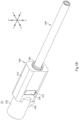
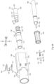
- FIG. 1A to 3B illustrate the connector C1 of the first embodiment.
- Figs. 1A to 3B show a Y-Y' direction (first direction).
- the Y-Y' direction includes a Y direction (one side in the first direction) and a Y' direction (the other side in the first direction).
- Figs. 1A to 1B and 2B to 3B show an X-X' direction (second direction).
- the X-X' direction is substantially orthogonal to the Y-Y' direction and includes an X direction (one side in the second direction) and an X' direction (the other side in the second direction).
- Figs. 1A to 2A and 3A to 3B show a Z-Z' direction (third direction).
- the Z-Z' direction is substantially orthogonal to the Y-Y' and X-X' directions and includes a Z direction (one side in the third direction) and a Z' direction (the other side in the third direction).
- the connector C1 is a coaxial connector.
- the connector C1 includes a shell 100 having electrical conductivity.
- the shell 100 may be constituted by an electrically conductive material (e.g., a metal or a carbon material such as a carbon nanotube).
- the shell 100 may include a tubular body, which is constituted by an insulating material, and a metal film, which is plated or vapor-deposited on an outer face of the tubular body.
- the shell 100 may, but is not required to, be fabricated by subjecting an electrically conductive bar to a machining process.
- the shell 100 includes a shell body 110 having a generally tubular shape, such as a generally circular or polygonal tubular shape (a generally tubular shape with a generally circular or polygonal cross section along the Z-Z' and the X-X' directions), and extending in the Y-Y' direction.
- the shell body 110 may be provided with neither a joint between two ends of a metal plate generated when the metal plate is formed into a tubular shape, a notch, nor a through hole.
- the shell 100 in its entirety may be provided with neither a joint, a notch, nor a through hole.
- the through holes if provided, extend through the shell body 110 or the shell 100 in a direction orthogonal to the Y-Y' direction.
- the shell body 110 includes a distal portion on a Y-direction side, a rear portion 112 on a Y'-direction side, an inner peripheral face 113 of generally tubular shape, such as a generally circular or polygonal tubular shape (a generally tubular shape with a generally circular or polygonal cross section along the Z-Z' and the X-X' directions), and an outer peripheral face.
- the distal portion of the shell body 110 includes a distal end 111, which is also a distal end on the Y-direction side of the shell 100. Note that the Y-Y' direction is an axial direction of the shell body 110.
- the shell 100 may further include at least one ringlike groove 120 and/or at least one ringlike protrusion 130.
- the at least one ringlike groove 120 will be hereinafter described as a single ringlike groove 120, but where a plurality of ringlike grooves 120 is provided, each of them is configured similarly to the single ringlike groove 120.
- the at least one ringlike protrusion 130 will be hereinafter described as a single protrusion 130, but where a plurality of protrusions 130 is provided, each of them is configured similarly to the single ringlike protrusion 130.
- the ringlike groove 120 is a recess of generally ringlike shape (generally circular or polygonal ringlike shape) provided in the inner peripheral face 113 of the shell body 110.
- the ringlike groove 120 is disposed such that a central axis of the ringlike groove 120 substantially coincides with a central axis of the shell body 110, and the ringlike groove 120 is recessed away from the central axis of the shell body 110 (see Figs. 2A and 2B ).
- the ringlike groove 120 communicates with the inside of the shell body 110.
- the ringlike groove 120 includes a bottom face having a generally ringlike shape (e.g., a generally circular or polygonal ringlike shape), a first wall face on the Y-direction side having a generally ringlike shape, and a second wall face on the Y'-direction side having a generally ringlike shape.
- a generally ringlike shape e.g., a generally circular or polygonal ringlike shape
- first wall face on the Y-direction side having a generally ringlike shape
- a second wall face on the Y'-direction side having a generally ringlike shape.
- the ringlike protrusion 130 is a ridge of generally ringlike shape (generally circular or polygonal ringlike shape) provided on the inner peripheral face 113 of the shell body 110.
- the ringlike protrusion 130 is disposed such that a central axis of the ringlike protrusion 130 substantially coincides with the central axis of the shell body 110, and the ringlike protrusion 130 protrudes toward the central axis of the shell body 110 (see Figs. 2A and 2B ).
- the ringlike protrusion 130 includes a top face having a generally ringlike shape (e.g., a generally circular or polygonal ringlike shape), a first wall face on the Y-direction side having a generally ringlike shape, and a second wall face on the Y'-direction side having a generally ringlike shape.
- a generally ringlike shape e.g., a generally circular or polygonal ringlike shape
- first wall face on the Y-direction side having a generally ringlike shape
- a second wall face on the Y'-direction side having a generally ringlike shape.
- the shell 100 may further include a bottom 140, a hole 150, and a cable holder 160.
- the bottom 140 is provided integrally with the rear portion 112 of the shell body 110 and forms a bottom on the Y'-direction side of the shell body 110 (see Figs. 2A to 3B ). As such, the shell body 110 and the bottom 140 constitute a generally close-bottomed tube.
- the bottom 140 includes a first face 141 on the Y-direction side. The first face 141 of the bottom 140 faces the inside of the shell body 110.
- the cable holder 160 is generally shaped like a column (e.g., a generally circular- or polygonal-section column) and extends from the bottom 140 in the Y' direction (see Figs. 2A to 3B ).
- the cable holder 160 may, but is not required to, have outer dimensions in a cross section along the X-X' and Z-Z' directions that are smaller than those of the shell body 110.
- the cable holder 160 includes an outer peripheral face of a generally tubular shape, such as a generally circular or polygonal tubular shape (a generally tubular shape with a generally circular or polygonal cross section along the Z-Z' and the X-X' directions), and a rear face on the Y'-direction side.
- the cable holder 160 can be omitted.
- the hole 150 extends in the Y-Y' direction through the bottom 140 and the cable holder 160 (see Figs. 2A and 2B ). Where the cable holder 160 is not provided, the hole 150 extends in the Y-Y' direction through the bottom 140. In either case, the hole 150 is a hole generally shaped like a column (e.g., a generally circular- or polygonal-section column), extends in the Y-Y' direction, and has dimensions in a cross section along the X-X' and Z-Z' directions that are smaller than inner dimensions in a cross section along the X-X' and Z-Z' directions of the shell body 110.
- a column e.g., a generally circular- or polygonal-section column
- the rear end of the cable holder 160 is a rear end of the shell 100.
- an end on the Y'-direction side of the bottom 140 is the rear end of the shell 100.
- the bottom 140, the hole 150, and the cable holder 160 can be omitted, in which case a rear end on the Y'-direction side of the shell body 110 is the rear end of the shell 100.
- the shell 100 may further include an engagement groove 170 of a generally ringlike shape (see Figs. 3A to 3B ).
- the engagement groove 170 is a recess of generally ringlike shape (generally circular or polygonal ringlike shape) provided in the outer peripheral face of the shell body 110.
- the engagement groove 170 is disposed such that a central axis of the engagement groove 170 substantially coincides with the central axis of the shell body 110, and the engagement groove 170 is recessed toward the central axis side of the shell body 110.
- the engagement groove 170 can be omitted.
- the connector C1 further includes a body 200.
- the body 200 is constituted by a molded insulating resin insert-molded inside the shell body 110 of the shell 100.
- the body 200 is entirely housed in the shell body 110 and exposed from the shell body 110 in the Y direction.
- the body 200 includes a main body 210.
- the main body 210 includes a distal portion 211, an intermediate portion 212, and a rear portion 213 (see Figs. 2Ato 2B ).
- the distal portion 211 of the main body 210 is generally shaped like a column (e.g., a generally circular- or polygonal-section column), extends in the Y direction from the intermediate portion 212, and is disposed inside the shell body 110.
- the intermediate portion 212 of the main body 210 is a portion between the distal portion 211 and the rear portion 213, is generally shaped like a column (e.g., a generally circular- or polygonal-section column), and is disposed inside the shell body 110.
- the rear portion 213 of the main body 210 is generally shaped like a column (e.g., a generally circular- or polygonal-section column), extends from the intermediate portion 212 in the Y' direction, and is disposed inside the shell body 110.
- the body 200 may further include a tube 220 (see Figs. 2A to 3B ).
- the tube 220 extends from the intermediate portion 212 in the Y direction and surrounds the distal portion 211 of the main body 210 with a generally ringlike clearance therebetween.
- the tube 220 have inner dimensions in a cross section along the X-X' and Z-Z' directions that are larger than outer dimensions in a cross section along the X-X' and Z-Z' directions of the distal portion 211 of the main body 210.
- the tube 220 can be omitted.
- an outer peripheral face of the intermediate portion 212 of the main body 210, an outer peripheral face of the rear portion 213 of the main body 210, and an outer peripheral face of the tube 220 together form an outer peripheral face of the body 200, and may be in intimate contact with the inner peripheral face 113 of the shell body 110.
- the intermediate portion 212 of the main body 210, the rear portion 213 of the main body 210, and the tube 220 each have outer dimensions in a cross section along the X-X' and Z-Z' directions that are equal to inner dimensions in a cross section along the X-X' and Z-Z' directions of the shell body 110.
- the tube 220 there may be a generally ringlike clearance between the distal portion 211 of the main body 210 and the shell body 110, or alternatively an outer peripheral face of the distal portion 211 of the main body 210 may be in intimate contact with the inner peripheral face 113 of the shell body 110.
- the outer dimensions in a cross section along the X-X' and Z-Z' directions of the distal portion 211 of the main body 210 are smaller than the inner dimensions in a cross section along the X-X' and Z-Z' directions of the shell body 110, and the outer peripheral face of the intermediate portion 212 and the outer peripheral face of the rear portion 213 of the main body 210 together form the outer peripheral face of the body 200 and are in intimate contact with the inner peripheral face 113 of the shell body 110.
- the outer dimensions in a cross section along the X-X' and Z-Z' directions of the distal portion 211 of the main body 210 are equal to the inner dimensions in a cross section along the X-X' and Z-Z' directions of the shell body 110, and the outer peripheral face of the distal portion 211, the outer peripheral face of the intermediate portion 212, and the outer peripheral face of the rear portion 213 of the main body 210 together form the outer peripheral face of the body 200 and are in intimate contact with the inner peripheral face 113 of the shell body 110.
- the body 200 has a first outermost end 201 and a second outermost end 202.
- the first outermost end 201 is an outermost end on the Y-direction side of the body 200.
- the first outermost end 201 may be a distal end on the Y-direction side of the tube 220 (see Figs. 2A and 2B ), or alternatively may be a distal end (not illustrated) on the Y-direction side of the distal portion 211 of the main body 210.
- the first outermost end 201 may be the distal end on the Y-direction side of the distal portion 211 of the main body 210.
- the second outermost end 202 is an outermost end on the Y'-direction side of the body 200.
- the second outermost end 202 may be a rear end on the Y'-direction side of the rear portion 213 of the main body 210.
- the shell 100 and the body 200 may further have either configuration (1) or (2) as follows:
- the shell 100 and the body 200 may further have one of the configurations (3) to (6) as follows:
- the body 200 further includes at least one ringlike protrusion 230 (see Figs. 2A to 3B ).
- the at least one ringlike protrusion 230 may be a single protrusion or a plurality of protrusions in accordance with the number of the at least one ringlike groove 120.
- the at least one ringlike protrusion 230 will be hereinafter described as a single protrusion 230, but where a plurality of ringlike protrusions 230 is provided, each of them is configured similarly to the single ringlike protrusion 230.
- the ringlike protrusion 230 is a ridge of generally ringlike shape (generally circular or polygonal ringlike shape) provided on the outer peripheral face of the body 200.
- the ringlike protrusion 230 is disposed such that a central axis of the ringlike protrusion 230 substantially coincides with the central axis of the shell body 110 of the shell 100.
- the ringlike protrusion 230 protrudes away from the central axis of the shell body 110 of the shell 100. In the other words, the ringlike protrusion 230 protrudes toward the ringlike groove 120 of the shell 100.
- the ringlike protrusion 230 fits in, and is in intimate contact with, the ringlike groove 120 of the shell 100.
- the ringlike protrusion 230 have an outer shape and outer dimensions that correspond to an inner shape and inner dimensions, respectively, of the ringlike groove 120.
- the ringlike protrusion 230 has a top face having a generally ringlike shape (e.g., a generally circular or polygonal ringlike shape), a first wall face on the Y-direction side having a generally ringlike shape, and a second wall face on the Y'-direction side having a generally ringlike shape.
- the top face of the ringlike protrusion 230 is in intimate contact with the bottom face of the ringlike groove 120
- the first wall face of the ringlike protrusion 230 is in intimate contact with the first wall face of the ringlike groove 120
- the second wall face of the ringlike protrusion 230 is in intimate contact with the second wall face of the ringlike groove 120.
- the body 200 further includes at least one ringlike groove 240 (see Figs. 2A to 3B ).
- the at least one ringlike groove 240 may be a single groove or a plurality of grooves in accordance with the number of the at least one ringlike protrusion 130.
- the at least one ringlike groove 240 will be hereinafter described as a single ringlike groove 240, but where a plurality of ringlike grooves 240 is provided, each of them is configured similarly to the single ringlike groove 240.
- the ringlike groove 240 is a recess of generally ringlike shape (generally circular or polygonal ringlike shape) provided in the outer peripheral face of the body 200.
- the ringlike groove 240 is disposed such that a central axis of the ringlike groove 240 substantially coincides with the central axis of the shell body 110 of the shell 100, and the ringlike groove 240 is recessed toward the central axis of the shell body 110 of the shell 100.
- the ringlike groove 240 is recessed relative to the ringlike protrusion 130 of the shell 100.
- the ringlike protrusion 130 of the shell 100 fits in, and is in intimate contact with, the ringlike groove 240.
- the ringlike groove 240 an inner shape and inner dimensions that correspond to an outer shape and outer dimensions, respectively, of the ringlike protrusion 130.
- the ringlike groove 240 includes a bottom face having a generally ringlike shape (e.g., a generally circular or polygonal ringlike shape), a first wall face on the Y-direction side having a generally ringlike shape, and a second wall face on the Y'-direction side having a generally ringlike shape.
- the top face of the ringlike protrusion 130 is in intimate contact with the bottom face of the ringlike groove 240
- the first wall face of the ringlike protrusion 130 is in intimate contact with the first wall face of the ringlike groove 240
- the second wall face of the ringlike protrusion 130 is in intimate contact with the second wall face of the ringlike groove 240.
- the body 200 further includes a housing hole 250 (see Figs. 2A to 3B ).
- the housing hole 250 is only required to extend through the body 200 in the Y-Y' direction.
- the housing hole 250 may extend through the main body 210 in the Y-Y' direction.
- a central axis of the housing hole 250 may coincide with the central axis of the shell body 110.
- the housing hole 250 may include a first hole 251 and a second hole 252.
- the first hole 251 is a hole generally shaped like a column (e.g., a generally circular- or polygonal-section column), extends in the Y-Y' direction, and opens in the Y direction.
- the second hole 252 is a hole extending from the first hole 251 in the Y' direction, communicates with the first hole 251, and opens in the Y' direction.
- the first hole 251 has dimensions in a cross section along the X-X' and Z-Z' directions that are smaller than those of the second hole 252.
- the first hole 251 and the second hole 252 can be omitted.
- the housing hole 250 may be a hole generally shaped like a column (e.g., a generally circular- or polygonal-section column) and extend in the Y-Y' direction.
- the housing hole 250 (specifically, if provided, the second hole 252 thereof) communicates with the hole 150 of the shell 100 (see Figs. 2A and 2B ).
- the housing hole 250 (specifically, if provided, the second hole 252 thereof) opens in the Y' direction (not illustrated).
- the connector C1 further includes a terminal 300.
- the terminal 300 is constituted by an electrically conductive material (e.g., a metal or a carbon material such as a carbon nanotube).
- the first terminal 300a may be disposed such that an imaginary line (not illustrated) extending in the Y-Y' direction through the center of the first terminal 300a substantially coincides with the central axis of the shell body 110. Accordingly, the terminal 300 and the shell body 110 form a coaxial structure.
- the terminal 300 includes a distal portion 310, an intermediate portion 320, and a rear portion 330.
- the intermediate portion 320 of the terminal 300 is a portion between the distal portion 310 and the rear portion 330.
- the intermediate portion 320 is constituted by, for example, a member having a generally tubular shape, such as a generally circular or polygonal tubular shape (a generally tubular shape with a generally circular or polygonal cross section along the Z-Z' and the X-X' directions), and extending in the Y-Y' direction (see Figs. 2A to 3B ), a rod extending in the Y-Y' direction (not illustrated), a plate extending in the Y-Y' direction (not illustrated), or the like.
- the intermediate portion 320 is at least partly housed and retained in the housing hole 250 of the body 200.
- the intermediate portion 320 is at least partly housed securely in the first hole 251 of the body 200.
- the intermediate portion 320 has an outer shape in a cross section along the X-X' and Z-Z' directions that is substantially the same as a shape in a cross section along the X-X' and Z-Z' directions of the housing hole 250 (specifically, if provided, the first hole 251 thereof) of the body 200, and the intermediate portion 320 has outer dimensions in a cross section along the X-X' and Z-Z' directions that are substantially equal to, or slightly smaller than, dimensions in a cross section along the X-X' and Z-Z' directions of the housing hole 250 (specifically, if provided, the first hole 251 thereof) of the body 200.
- the distal portion 310 of the terminal 300 is constituted by a member having a generally tubular shape, such as a generally circular or polygonal tubular shape (a generally tubular shape with a generally circular or polygonal cross section along the Z-Z' and the X-X' directions), and extending from the intermediate portion 320 in the Y direction (see Figs. 2A to 3B ), a pair of beams extending from the intermediate portion 320 in the Y direction (see Figs. 7A and 7B to be described), a rod (not illustrated) extending from the intermediate portion 320 in the Y direction, a plate (not illustrated) extending from the intermediate portion 320 in the Y direction, or the like.
- a generally tubular shape such as a generally circular or polygonal tubular shape (a generally tubular shape with a generally circular or polygonal cross section along the Z-Z' and the X-X' directions)
- a pair of beams extending from the intermediate portion 320 in the Y direction
- the distal portion 310 may protrude in the Y direction from the housing hole 250 of the body 200 and be disposed inside the shell body 110 (see Figs. 2A to 2B ), or alternatively may be disposed in the housing hole 250 of the body 200 and exposed in the Y direction from the housing hole 250 (see Figs. 6A and 6B to be described).
- the rear portion 330 of the terminal 300 is constituted by a member having a generally tubular shape, such as a generally circular or polygonal tubular shape (a generally tubular shape with a generally circular or polygonal cross section along the Z-Z' and the X-X' directions), and extending from the intermediate portion 320 in the Y' direction(see Figs. 2A to 3B ), a rod (not illustrated) from the intermediate portion 320 extending in the Y' direction, a plate (not illustrated) extending from the intermediate portion 320 in the Y' direction, or the like.
- a generally tubular shape such as a generally circular or polygonal tubular shape (a generally tubular shape with a generally circular or polygonal cross section along the Z-Z' and the X-X' directions), and extending from the intermediate portion 320 in the Y' direction(see Figs. 2A to 3B ), a rod (not illustrated) from the intermediate portion 320 extending in the Y' direction, a plate (not illustrated
- the rear portion 330 is disposed in the housing hole 250 (specifically, if provided, the second hole 252 thereof) of the body 200 (see Figs. 2A and 2B ).
- the rear portion 330 may be disposed in the housing hole 250 (specifically, if provided, the second hole 252 thereof) of the body 200 (not illustrated), or alternatively may protrude in the Y' direction from the housing hole 250 (specifically, if provided, the second hole 252 thereof) of the body 200 and be disposed inside the shell body 110 (not illustrated).
- the terminal 300 may further include a first portion 301.
- the first portion 301 is a portion in the Y-Y' direction of the terminal 300.
- the first portion 301 is provided in the distal portion 310, the intermediate portion 320, or the rear portion 330 of the terminal 300.
- the terminal 300 may further include at least one second portion 302 and/or at least one third portion 303.
- the at least one second portion 302 will be hereinafter described as a single second portion 302, but where a plurality of second portions 302 is provided, each of them is configured similarly to the single second portion 302.
- the at least one third portion 303 will be hereinafter described as a single third portion 303, but where a plurality of third portions 303 is provided, each of them is configured similarly to the single third portion 303.
- the second portion 302 is another portion in the Y-Y' direction of the terminal 300 that does not include the first portion 301, and is higher in impedance than the first portion 301.
- the second portion 302 is provided in the distal portion 310, the intermediate portion 320, or the rear portion 330 of the terminal 300.
- a main factor is that the second portion 302 has outer dimensions in a cross section along the X-X' and Z-Z' directions that are larger than those of the first portion 301. The larger the outer dimensions in a cross section along the X-X' and Z-Z' directions of the second portion 302 are, the higher the impedance of the second portion 302 is.
- the third portion 303 is another portion in the Y-Y' direction of the terminal 300 that does not include the first portion 301, and is lower in impedance than the first portion 301. Where the second portion 302 and the third portion 303 are provided, the second portion 302 and the third portion 303 are different portions in the Y-Y' direction of the terminal 300.
- the third portion 303 is provided in the distal portion 310, the intermediate portion 320, or the rear portion 330 of the terminal 300.
- a main factor is that the third portion 303 has outer dimensions in a cross section along the X-X' and Z-Z' directions that are smaller than those of the first portion 301. The smaller the outer dimensions in a cross section along the X-X' and Z-Z' directions of the second portion 302 are, the lower the impedance of the second portion 302 is.
- a possible way to find out a portion with a higher impedance (the second portion 302) and/or a portion with a lower impedance (the third portion 303) in the Y-Y' direction of the terminal 300 is to input CAD data of the connector C1 to a high frequency simulator in order to build a model, and then to conduct a simulation based on the information of the model or other information.
- the high frequency simulators include Femtet (registered trademark), which is an application program made by Murata Software Co., Ltd., and Ansys HFSS ("Ansys" is a registered trademark), which is an application program made by ANSYS, Inc.
- the ringlike groove 120 of the shell 100 surrounds, and is recessed away from, the second portion 302 of the terminal 300 (see Figs. 2A and 2B ).
- a depth dimension of the ringlike groove 120 a linear distance in a direction orthogonal to the Y-Y' direction (hereinafter referred to as an "orthogonal direction") from the inner peripheral face 113 of the shell body 110 of the shell 100 to the bottom face of the ringlike groove 120
- an orthogonal direction a linear distance in the orthogonal direction from the bottom face of the ringlike groove 120 to the second portion 302 of the terminal 300 increases so as to lower the impedance of the second portion 302 of the terminal 300.
- the depth dimension of the ringlike groove 120 may be determined in accordance with the impedance of the second portion 302 of the terminal 300.
- CAD data of the connector C1 with different depth dimensions of the ringlike groove 120 may be input to the high frequency simulator to build models, and a plurality of sets of simulation may be conducted based on the information of the models and other information to determine the depth dimension of the ringlike groove 120 such that the impedance of the second portion 302 of the terminal 300 is substantially the same as, or close to, the impedance of the first portion 301 of the terminal 300.
- the ringlike protrusion 130 of the shell 100 surrounds, and protrude toward, the third portion 303 of the terminal 300 (see Figs. 2A and 2B ).
- a height dimension of the ringlike protrusion 130 a linear distance in a direction orthogonal to the Y-Y' direction from the inner peripheral face 113 of the shell body 110 of the shell 100 to the top face of the ringlike protrusion 130
- a linear distance in the orthogonal direction from the top face of the ringlike protrusion 130 to the third portion 303 of the terminal 300 decreases so as to raise the impedance of the third portion 303 of the terminal 300.
- the height dimension of the ringlike protrusion 130 may be determined in accordance with the impedance of the third portion 303 of the terminal 300.
- CAD data of the connector C1 with different height dimensions of the ringlike protrusion 130 may be input to the high frequency simulator to build models, and a plurality of sets of simulation may be conducted based on the information of the models and other information to determine the height dimension of the ringlike protrusion 130 such that the impedance of the third portion 303 of the terminal 300 is substantially the same as, or close to, the impedance of the first portion 301 of the terminal 300.
- the ringlike groove 120 of the shell 100 can be omitted. Where the ringlike groove 120 of the shell 100 is omitted, the ringlike protrusion 230 of the body 200 is also omitted. Even where the third portion 303 of the terminal 300 is provided, the ringlike protrusion 130 of the shell 100 can be omitted. Where the ringlike protrusion 130 of the shell 100 is omitted, the ringlike groove 240 of the body 200 is also omitted.
- the second portion 302 of the terminal 300 can be omitted. In this case, the ringlike groove 120 of the shell 100 and the ringlike protrusion 230 of the body 200 can, but is not required to, be omitted.
- the third portion 303 of the terminal 300 can be omitted. In this case, the ringlike protrusion 130 of the shell 100 and the ringlike groove 240 of the body 200 can, but is not required to, be omitted.
- the connector C1 further includes a cable 400.
- the cable 400 is partly received inside the shell body 110 from the Y'-direction side and connected to the rear portion 330 of the terminal 300 inside the shell body 110.
- the cable 400 is a coaxial cable.
- the cable 400 includes an outer insulator 410, an outer conductor 420, an inner insulator 430, and an inner conductor 440.
- the outer insulator 410 is a generally tubular jacket constituted by an insulating material.
- the outer conductor 420 is a generally tubular member constituted by a conductor, such as a copper wire mesh, and is disposed inside the outer insulator 410. In other words, the outer conductor 420 is covered by the outer insulator 410.
- the outer conductor 420 includes a distal portion on the Y-direction side. The distal portion of the outer conductor 420 protrudes from the outer insulator 410 in the Y direction.
- the inner insulator 430 is a tube constituted by an insulating material and is disposed inside the outer conductor 420.
- the inner insulator 430 includes a distal portion on the Y-direction side. The distal portion of the inner insulator 430 protrudes from the outer conductor 420 in the Y direction.
- the inner conductor 440 is a metal wire, such as a copper wire, and is disposed inside the inner insulator 430.
- the inner conductor 440 includes a distal portion on the Y-direction side. The distal portion of the inner conductor 440 protrudes from the inner insulator 430 in the Y direction.
- the distal portion of the inner insulator 430 of the cable 400 has an outer shape in a cross section along the X-X' and Z-Z' directions that is substantially the same as a shape in a cross section along the X-X' and Z-Z' directions of the hole 150 of the shell 100, and the distal portion of the inner insulator 430 of the cable 400 has outer dimensions in a cross section along the X-X' and Z-Z' directions that are substantially equal to, or slightly smaller than, the dimensions in a cross section along the X-X' and Z-Z' directions of the hole 150 of the shell 100 (see Figs. 2A and 2B ).
- the distal portion of the inner insulator 430 of the cable 400 fits in the hole 150 of the shell 100.
- the distal portion of the inner conductor 440 of the cable 400 is received in the housing hole 250 (specifically, if provided, the second hole 252 thereof) of the body 200 and is connected to the rear portion 330 of the terminal 300 in the housing hole 250 (specifically, if provided, the second hole 252 thereof).
- the distal portion of the outer conductor 420 of the cable 400 fits over, and is connected to, the cable holder 160 (see figs. 2A and 2B ).
- the distal portion of the outer conductor 420 of the cable 400 is in contact with, and connected to, the shell 100 (not illustrated).
- the distal portion of the inner insulator 430 of the cable 400 and the distal portion of the inner conductor 440 of the cable 400 are received inside the shell body 110 of the shell 100 from the Y'-direction side, and the distal portion of the inner conductor 440 of the cable 400 is connected to the rear portion 330 of the terminal 300 in the housing hole 250 (specifically, if provided, the second hole 252 thereof) of the body 200.
- the distal portion of the outer conductor 420 of the cable 400 may be in contact with, and connected to, the shell body 110.
- the shell 100 and the body 200 have one of configurations (3) to (6) described above and the rear portion 330 of the terminal 300 protrudes from the housing hole 250 (specifically, if provided, the second hole 252 thereof) of the body 200 in the Y' direction (not illustrated), the distal portion of the inner insulator 430 of the cable 400 and the distal portion of the inner conductor 440 of the cable 400 are received inside the shell body 110 of the shell 100 from the Y'-direction side, and the distal portion of the inner conductor 440 of the cable 400 is connected to the rear portion 330 of the terminal 300 inside the shell body 110.
- the distal portion of the outer conductor 420 of the cable 400 may be in contact with, and connected to, the shell body 110.
- the connector C1 may further include a conductive ring 500 (see Figs. 1A to 3B ).
- the conductive ring 500 is constituted by a conductor (e.g., a metal or the like material) shaped into a ring shape.
- the conductive ring 500 fits over the distal portion of the outer conductor 420 of the cable 400, which fits over the cable holder 160, and a distal portion on the Y-direction side of the outer insulator 410 of the cable 400.
- the thus arranged conductive ring 500 is fixed to the cable holder 160 via the distal portion of the outer conductor 420, and also fixed to the distal portion of the outer insulator 410 of the cable 400.
- the conductive ring 500 may be, but is not required to, be at least partly swaged so as to be fixed to the cable holder 160 via the outer conductor 420 and to be fixed to the distal portion of the outer insulator 410 of the cable 400.
- the conductive ring 500 can be omitted.
- the connector C1 may further include a housing 600 (see Figs. 1A to 3B ).
- the housing 600 is constituted by an insulating material (e.g., an insulating resin or the like).
- the housing 600 includes a housing body 610 and a connecting portion 620.
- the housing body 610 has a generally rectangular tube (a generally tubular shape with a generally rectangular cross section along the Z-Z' and the X-X' directions) extending in the Y-Y' direction.
- the housing body 610 includes a housing space 611 therein.
- the housing space 611 extends in the Y-Y' direction through the housing body 610.
- the connecting portion 620 is a generally tubular member extending from the housing body 610 in the Y direction. The inside of the connecting portion 620 communicates with the housing space 611 of the housing body 610.
- a portion on the Y'-direction side of the shell 100 is securely housed in the housing space 611 of the housing body 610.
- a portion on the Y-direction side of the shell 100 is disposed in the connecting portion 620.
- the conductive ring 500 is provided, the conductive ring 500 is disposed in the housing space 611, and the cable 400 is led out of the housing space 611 in the Y' direction.
- the conductive ring 500 is not provided, the cable 400 is led out of the housing space 611 in the Y' direction.
- An engagement hole 612 may be provided in a wall on the X'-direction side of the housing body 610.
- the engagement hole 612 includes a first hole on the Z-direction side, a second hole on the Z'-direction side, a coupling groove, a first engaging portion on the Z-direction side, and a second engaging portion on the Z'-direction side.
- the first hole and the second hole are provided in the wall on the X'-direction side of the housing body 610, extend in the X direction, are located on the Z-direction side and the Z'-direction side, respectively, relative to the housing space 611, communicate with the housing space 611, and open in the X direction.
- the coupling groove is provided in the wall on the X'-direction side of the housing body 610 and extends from the first hole to the second hole.
- the first engaging portion is an edge on the Z'-direction side of an opening on the X-direction side of the first hole, a protrusion on the edge, or the like.
- the second engaging portion is an edge on the Z-direction side of an opening on the X-direction side of the second hole, a protrusion on the edge, or the like.
- the housing 600 may further include a locking portion 630.
- the locking portion 630 extends from the housing body 610 and along the connecting portion 620 in the Y direction.
- the locking portion 630 is provided with a protrusion 631 protruding in the Z direction.
- the connector C1 may further include a retainer 700 (see Figs. 1Ato 3B ).
- the retainer 700 is a substantially C-shaped member and includes first and second engagement arms 710 and a coupling portion 720.
- a distance in the Z-Z' direction between the first and second engagement arms 710 is slightly smaller than that from a portion on the Z-direction side to a portion on the Z'-direction side of a bottom of the engagement groove 170.
- the first engagement arm 710 extends in the X direction from an end on the Z-direction side of the coupling portion 720, and includes a free end portion with a claw protruding to the Z'-direction side.
- the second engagement arm 710 extends in the X direction from an end on the Z'-direction side of the coupling portion 720, and includes a free end portion with a claw protruding to the Z-direction side.
- the coupling portion 720 is received in the coupling groove of the engagement hole 612 of the housing 600.
- the first engagement arm 710 is received in the first hole of the engagement hole 612 of the housing 600, and the claw of the first engagement arm 710 is hooked on the first engaging portion of the engagement hole 612.
- the second engagement arm 710 is received in the second hole of the engagement hole 612 of the housing 600, and the claw of the second engagement arm 710 is hooked on the second engaging portion of the engagement hole 612.
- the first and second engagement arms 710 thus elastically retain the shell body 110 therebetween and are fixed to the housing 600.
- the engagement groove 170 of the shell 100 can be omitted.
- the retainer 700 is only required to elastically retain the shell body 110. Further, it is possible to omit the engagement groove 170 of the shell 100, the engagement hole 612 of the housing 600, and the retainer 700. It is also possible to omit the entire housing 600 along with the omission of the engagement groove 170 of the shell 100 and the retainer 700.
- FIG. 4A illustrates a molding device for insert-molding the body 200 inside the shell body 110 of the shell 100
- Fig. 4B is an enlarged view of a portion ⁇ of the molding device.
- the shell 100 is prepared including the shell body 110, the bottom 140, the hole 150, and the cable holder 160. Also prepare is a shell retainer H having a generally tubular shape and extending in the Y-Y' direction. The shell 100 is fitted into the shell retainer H. In other words, the shell retainer H is fitted over the shell 100.
- a first mold 10 and a second mold 20 of the molding device are closed together, and the shell retainer H and the shell 100 are housed in a cavity of the first mold 10 and the second mold 20 (see Figs. 4A and 4B ).
- the first mold 10 includes a first insert 11, and the second mold 20 includes a second insert 21.
- first outermost end 201 of the body 200 is located on the Y'-direction side relative to the distal end 111 of the shell body 110
- first insert 11 is inserted into the shell body 110 from the Y-direction side to block the shell body 110 with the first insert 11 from the Y-direction side
- second insert 21 is inserted into the hole 150 and the shell body 110 of the shell 100 from the Y'-direction side to bring the second insert 21 into abutment with the first insert 11 and to block the shell body 110 with the second insert 21 from the Y'-direction side.
- the shell body 110, the first insert 11, and the second insert 21 define an injection space, and a gate G in the first insert 11 is brought into communication with the injection space.
- the injection space corresponds to a shape and size of the body 200 according to one of the above aspects.
- a portion of the second insert 21 that is inserted into the shell body 110 corresponds to a shape and size of the housing hole 250 of the body 200.
- a portion of the second insert 21 that is inserted into in the hole 150 fits in the hole 150, so that the shell body 110 is blocked with the second insert 21 from the Y'-direction side.
- the gate G is a pin gate and includes an injection port to be disposed inside the shell body 110 and communicate with the injection space.
- the injection port of the gate G may communicate with a portion of the injection space that corresponds to a distal face of the distal portion 211 of the main body 210 of the body 200 according to one of the above aspects.
- the injection port may communicate with a portion of the injection space that corresponds to the first outermost end 201, which is not the distal face of the distal portion 211 of the main body 210, of the body 200.
- the first insert 11 may not be inserted into the shell body 110 of the shell 100 but block the shell body 110 of the shell 100 from the Y-direction side.
- the second insert 21 may be inserted into the shell body 110 of the shell 100 from the Y'-direction side to abut on the first insert 11 and to block the shell body 110 from the Y'-direction side.
- the second insert 21 includes a portion to be inserted into the shell body 110 and a portion to block the shell body 110 from the Y'-direction side.
- the shell retainer H can be omitted.
- the cavity may house only the shell 100 according to one of the above aspects.
- a molten resin is injected through the gate G and charged into the injection space.
- the charged molten resin thus adheres to the inner peripheral face 113 of the shell body 110.
- the charged molten resin also adheres to the first face 141 of the bottom 140.
- the ringlike groove 120 is provided, the molten resin is charged also into the ringlike groove 120 and adheres also to the bottom face, the first wall face, and the second wall face of the ringlike groove 120.
- the filled molten resin adheres also to the top face, the first wall face, and the second wall face of the ringlike protrusion 130.
- the first mold 10 and the second mold 20 are opened apart from each other, and the first insert 11 and the second insert 21 are removed from the shell 100 and the body 200.
- the portion of the second insert 21 that has been inserted in the shell body 110 is removed from the body 200, so that the housing hole 250 is formed in the body 200.
- the housing hole 250 in the body 200 communicates with the hole 150.
- the housing hole 250 in the body 200 opens in the Y' direction through the shell body 110.
- the terminal 300 and the cable 400 are prepared.
- the distal portion of the inner conductor 440 of the cable 400 is connected to the rear portion 330 of the terminal 300.
- the distal portion of the outer conductor 420 of the cable 400 is inserted into the conductive ring 500.
- this insertion step is omitted.
- the terminal 300 connected to the cable 400 is inserted from the hole 150 of the shell 100 into the housing hole 250 of the body 200.
- the distal portion 310 of the terminal 300 is disposed in the housing hole 250 of the body 200 and exposed to the Y-direction side, or alternatively the distal portion 310 of the terminal 300 protrudes in the Y direction out of the housing hole 250 of the body 200 and is disposed inside the shell body 110 of the shell 100.
- the intermediate portion 320 of the terminal 300 is disposed, and at least partly retained, in the housing hole 250 of the body 200.
- the rear portion 330 of the terminal 300 is disposed in the housing hole 250 of the body 200.
- the distal portion of the inner conductor 440 of the cable 400 is inserted from the hole 150 of the shell 100 into the housing hole 250 of the body 200 and disposed in the housing hole 250.
- the terminal 300 is provided with the second portion 302
- the second portion 302 is disposed inside the ringlike groove 120 of the shell 100.
- the terminal 300 is provided with the third portion 303, when the terminal 300 is retained in the housing hole 250 of the body 200, the third portion 303 is disposed inside the ringlike protrusion 130 of the shell 100.
- the distal portion of the inner insulator 430 of the cable 400 is fitted in the hole 150 of the shell 100 to block the hole 150.
- the distal portion of the outer conductor 420 of the cable 400 is fitted over the cable holder 160.
- the conductive ring 500 is provided, the conductive ring 500 is placed to surround the cable holder 160 by fitting the distal portion of the outer conductor 420 of the cable 400 over the cable holder 160.
- the conductive ring 500 is partly swaged and thereby brought into pressure contact with the cable holder 160 via the distal portion of the outer conductor 420 of the cable 400.
- the conductive ring 500 is thus fixed to the cable holder 160 via the distal portion of the outer conductor 420 of the cable 400, and the distal portion of the outer conductor 420 of the cable 400 is electrically connected to the cable holder 160.
- the distal portion of the outer conductor 420 of the cable 400 is electrically connected to the cable holder 160 by fitting the distal portion of the outer conductor 420 of the cable 400 over the cable holder 160.
- the terminal 300 is inserted from the hole 150 of the shell 100 into the housing hole 250 of the body 200, the distal portion of the inner conductor 440 of the cable 400 is inserted from the hole 150 of the shell 100 into the housing hole 250 of the body 200, and the distal portion of the inner insulator 430 of the cable 400 is fitted in the hole 150 of the shell 100 to block the hole 150.
- the distal portion of the outer conductor 420 of the cable 400 may or may not be brought into contact and electrical connection with the shell 100.
- the terminal 300 connected to the cable 400 is inserted from the shell body 110 of the shell 100 into the housing hole 250 of the body 200.
- the distal portion 310 of the terminal 300 is disposed in the housing hole 250 of the body 200 and exposed to the Y-direction side, or alternatively the distal portion 310 of the terminal 300 protrudes in the Y direction out of the housing hole 250 of the body 200 and is disposed inside the shell body 110 of the shell 100.
- the intermediate portion 320 of the terminal 300 is disposed, and at least partly retained, in the housing hole 250 of the body 200.
- the rear portion 330 of the terminal 300 is disposed in the housing hole 250 of the body 200.
- the distal portion of the inner conductor 440 of the cable 400 is inserted from the shell body 110 of the shell 100 into the housing hole 250 of the body 200 and disposed in the housing hole 250.
- the distal portion of the outer conductor 420 of the cable 400 may or may not be brought into contact and electrical connection with the shell 100.
- the housing 600 is prepared after the terminal 300 and the cable 400 are assembled into the shell 100.
- the shell 100 is then inserted from the Y'-direction side into the housing space 611 of the housing 600.
- the portion on the Y-direction side of the shell 100 is inserted from the housing space 611 into the connecting portion 620, and the portion on the Y'-direction side of the shell 100 is securely housed in the housing space 611 of the housing body 610.
- the retainer 700 is prepared.
- the first and second engagement arms 710 of the retainer 700 are inserted from the X'-direction side into the first and second holes, respectively, of the engagement hole 612 of the housing 600.
- the first and second engagement arms 710 are inserted into the portion on the Z-direction side and the portion on the Z'-direction side, respectively, of the engagement groove 170 of the shell body 110 of the shell 100 and elastically retain the shell body 110 therebetween, and the claws of the first and second engagement arms 710 are hooked onto the first and second engaging portions, respectively, of the engagement hole 612.
- the first and second engagement arms 710 of the retainer 700 are fixed to the housing 600, and the shell body 110 is fixed to the housing 600. This is how the connector C1 is manufactured.
- the step of attaching the retainer 700 to the housing 600 can simply be omitted.
- the step of assembling the shell 100 and other components into the housing 600 and the step of attaching the retainer 700 to the housing 600 can simply be omitted.
- the connector C1 and the method for manufacturing the connector C1 provides technical features and effects (1) to (7) as follows.
- the connector C1 has improved EMI characteristics for the following reasons.
- the body 200 is insert-molded, and entirely housed, inside the shell body 110.
- the intermediate portion 320 of the terminal 300 is at least partly retained in the housing hole 250 of the body 200, and the terminal 300 is entirely disposed inside the shell body 110.
- the cable 400 is connected to the rear portion 330 of the terminal 300 inside the shell body 110.
- the entire terminal 300 and the part where the terminal 300 and the cable 400 are connected together are disposed inside the shell body 110 and shielded by the shell body 110, resulting in improved EMI characteristics of the connector C1.
- the shell body 110 is provided with neither a joint, a notch, nor a through hole,
- the connector C1 has further improved EMI characteristics.
- the connector C1 is easy to manufacture for the following reasons.
- the body 200 can be insert-molded in the shell body 110 because the body 200 is disposed inside the shell body 110 and exposed to the Y-direction side. Since the body 200 is insert-molded in the shell body 110, it is advantageously possible to omit the step of assembling the body 200 into the shell body 110.
- the body 200 is provided with the housing hole 250, and simply by inserting the terminal 300 into the housing hole 250, the intermediate portion 320 of the terminal 300 is at least partly retained by the body 200. It is therefore easy to assemble the terminal 300 into the body 200.
- the connector C1 is easy to manufacture.
- a fine air layer or layers may be generated in an interface between the body 200 and the shell body 110.
- the presence of the air layer or layers on the periphery of a part of the terminal 300 may cause an increase in impedance of the part of the terminal 300.
- the presence of the air layer or layers may cause an enlarged clearance between the body 200 and the shell body 110 of the shell 100, which may result in wobbling, positional displacement, or the like of the body 200 inside the shell body 110.
- the connector C1 is configured such that the body 200 is insert-molded inside the shell body 110, with the outer peripheral face of the body 200 in intimate contact with the shell body 110.
- This configuration reduces the possibility of the above-described generation of air layer or layers, facilitating the impedance adjustment of the terminal 300.
- this configuration also results in a reduced clearance between the body 200 and the shell body 110 of the shell 100, advantageously suppressing wobbling, positional displacement, or the like of the body 200 inside the shell body 110.
- the shell 100 is provided with the at least one ringlike groove 120 and the terminal 300 is provided with the first portion 301 and the at least one second portion 302 having an impedance higher than that of the first portion 301, it is easy to adjust the impedance of the terminal 300. Since the or each ringlike groove 120 surrounds, and is recessed away from, the or a corresponding second portion 302 of the terminal 300, the impedance of the or each second portion 302 can be lowered such as to be substantially the same or close to the impedance of the first portion 301 of the terminal 300. Moreover, where the shell 100 is fabricated by a machining process, the at least one ringlike groove 120 can be fabricated with high precision in terms of dimensions, positions, etc. This allows the at least one second portion 302 to be adjusted in impedance adjustment with high precision.
- the shell 100 is provided with the at least one ringlike protrusion 130 and the terminal 300 is provided with the first portion 301 and the at least one third portion 303 having an impedance lower than that of the first portion 301, it is easy to adjust the impedance of the terminal 300. Since the or each ringlike protrusion 130 surrounds, and protrudes toward, the or a corresponding third portion 303 of the terminal 300, the impedance of the or each third portion 303 can be increased such as to be substantially the same or close to the impedance of the first portion 301 of the terminal 300.
- the at least one ringlike protrusion 130 can be fabricated with high precision in terms of dimensions, positions, etc. This allows the at least one third portion 303 to be adjusted in impedance adjustment with high precision.
- the body 200 is restricted in position in the Y-Y' direction relative to the shell body 110 of the shell 100. This is because the or each ringlike protrusion 230 of the body 200 fits in the or a corresponding ringlike groove 120 of the shell body 110 and/or the or each ringlike protrusion 130 of the shell body 110 fits in the or a corresponding ringlike groove 240 of the body 200.
- the connector C1 provides a larger allowable range for the connection of the mating connector in an inclined orientation, or in an offset position in the X-X' and/or Z-Z' direction, relative to the connector C1.
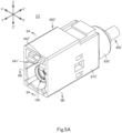
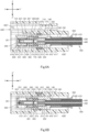
- FIG. 5A to 7B show the connector C2 according to a plurality of embodiments of the invention, including the second embodiment and its variants, and will now be described with reference to Figs. 5A to 7B .
- the connector C2 has configuration similar to those of the connector C1, except that the connector C2 is a mating connector connectable to the connector C1.
- the connector C2 will be described focusing on the differences from the connector C1 and omitting overlapping descriptions.
- Figs. 5A to 7B also show the Y-Y' direction (first direction) similarly to Figs. 1A to 3B .
- Figs. 5A to 5B and 6B to 7B also show the X-X' direction (second direction) similarly to Figs. 1A , 1B , and 2B to 3B .
- Figs. 5A to 6A and 7A to 7B also show the Z-Z' direction (third direction) similarly to Figs. 1A to 2A and 3A to 3B .
- a terminal 300 of the connector C2 has the same configuration as the terminal 300 of the connector C1, except that a distal portion 310 thereof is connectable to the distal portion 310 of the terminal 300 of the connector C1.
- one of the distal portion 310 of the terminal 300 of the connector C1 and the distal portion 310 of the terminal 300 of the connector C2 may have a female shape (e.g., shaped like a pair of arms, have a generally tubular shape or the like shape), and the other distal portion 310 may have a male shape (e.g., shaped like a rod, a plate, or the like).
- the distal portion 310 of the terminal 300 of the connector C1 protrudes in the Y direction from the housing hole 250 of the body 200 of the connector C1
- the distal portion 310 of the terminal 300 of the connector C2 may be disposed in an housing hole 250 of a body 200 of the connector C2 and exposed in the Y direction from the housing hole 250 (see Figs. 6A and 6B ).
- the distal portion 310 of the terminal 300 of the connector C1 is disposed in the housing hole 250 of the body 200 of the connector C1 and exposed in the Y direction from the housing hole 250, the distal portion 310 of the terminal 300 of the connector C2 may protrude in the Y direction from the housing hole 250 of the body 200 of the connector C2 (not illustrated).
- the distal portion 310 of the terminal 300 of the connector C1 is disposed in the housing hole 250 of the body 200 of the connector C1 and exposed in the Y direction from the housing hole 250
- the distal portion 310 of the terminal 300 of the connector C2 may be disposed in the housing hole 250 of the body 200 of the connector C2 and exposed in the Y direction from the housing hole 250 (not illustrated).
- the distal portion 310 of the terminal 300 of the connector C2 is connected to the distal portion 310 of the terminal 300 of the connector C1
- the distal portion 211 of the body 200 of the connector C1 may be received in the ringlike gap in the housing hole 250 around the distal portion 310 of the terminal 300 of the connector C2, but reversed arrangements may be adopted.
- the terminal 300 of the connector C2 may or may not include a first portion 301 and at least one second portion 302 and/or at least one third portion 303.
- a distal portion of a shell body 110 of the connector C2 may removably receive the distal portion of the shell body 110 of the connector C1.
- the distal portion of the shell body 110 of the connector C2 has an inner shape in a cross section along the X-X' and Z-Z' directions that is substantially the same as an outer shape in a cross section along the X-X' and Z-Z' directions of the distal portion of the shell body 110 of the connector C1.
- the distal portion of the shell body 110 of the connector C2 has inner dimensions in a cross section along the X-X' and Z-Z' directions that are larger than outer dimensions in a cross section along the X-X' and Z-Z' directions of the distal portion of the shell body 110 of the connector C1.
- the shell body 110 of the shell 100 of the connector C2 may or may not include at least one ringlike groove 120 and/or at least one ringlike protrusion 130.
- the body 200 of the connector C2 includes a tube 220, there is a generally ringlike gap between the distal portion 211 of a main body 210 of the body 200 and the shell body 110.
- the tube 220 of the body 200 of the connector C2 if provided, surrounds a basal portion on the Y'-direction side of the distal portion 211 of the main body 210 with a generally ringlike gap therebetween.
- the body 200 of the connector C2 may or may not include at least one ringlike protrusion 230 and/or at least one ringlike groove 240.
- the body 200 of the connector C2 may further include at least one abutment 260 in place of the at least one ringlike groove 240.
- the at least one abutment 260 may be a single abutment or a plurality of abutments in accordance with the number of the at least one ringlike protrusion 130.
- the at least one abutment 260 will be hereinafter described as a single abutment 260, but where a plurality of abutments 260 is provided, each of them is configured similarly to the single abutment 260.
- the abutment 260 may be constituted by a distal portion on the Y-direction side of the tube 220, or alternatively by a part of the main body 210.
- the abutment 260 is constituted by a part of the main body 210. In either case, the abutment 260 abuts the ringlike protrusion 130 from the Y'-direction side.
- the body 200 may include the at least one abutment 260 in addition to the at least one ringlike groove 240.
- the at least one abutment 260 can be omitted.
- the connector C2 may further include a ground terminal 800.
- the ground terminal 800 includes a first ring 810, a second ring 820, and a plurality of contact springs 830.
- the first ring 810 and the second ring 820 are C-shaped or circular-ring shaped metal plates configured to be reduced in diameter when elastically deformed, and are arranged in spaced relation to each other in the Y-Y' direction.
- the contact springs 830 are provided between the first ring 810 and the second ring 820 and arranged in spaced relation to each other along the circumferential direction of the first ring 810.
- Each of the contact springs 43 is curved in an arc shape such that an intermediate portion thereof protrudes toward an imaginary line extending in the Y-Y' direction through the centers of the first ring 810 and the second ring 820.
- the ground terminal 800 is housed inside the shell body 110 of the shell 100 and surrounds the distal portion 211 of the main body 210.
- the first ring 810 and the second ring 820 of the ground terminal 800 is in elastic contact and electrical connection with an inner peripheral face 113 of the shell body 110, and the contact springs 830 of the ground terminal 800 surround the distal portion 310 of the terminal 300 disposed in the housing hole 250 of the body 200.
- the ground terminal 800 can be omitted.
- the distal portion of the shell body 110 of the connector C1 received inside the distal portion of the shell body 110 of the connector C2
- the distal portion of the shell body 110 of the connector C2 and the distal portion of the shell body 110 of the connector C1 may be in contact with each other.
- the connector C2 may include a housing 600'.
- the housing 600' of the connector C2 is different in configuration from the housing 600 of the connector C1 as described below.
- the housing 600' includes a housing body 610' and a tube 630'.
- the housing body 610' has a generally rectangular tube (a generally tubular shape with a generally rectangular cross section along the Z-Z' and the X-X' directions) extending in the Y-Y' direction.
- the housing body 610 includes a housing space 611' therein.
- the housing space 611' extends in the Y-Y' direction through the housing body 610' and is configured to removably receive the connecting portion 620 of the housing 600 of the connector C1.
- the tube 630' is a generally tubular member extending in the Y' direction from the housing body 610'. The inside of the tube 630' communicates with the housing space 611' of the housing body 610'.
- the shell 100 is securely housed in the housing space 611' of the housing body 610'.
- the conductive ring 500 is disposed in the housing space 611' and inside the tube 630', and the cable 400 is led out of the tube 630' in the Y' direction.
- the cable 400 is led out of the tube 630' in the Y' direction.
- the housing body 610' of the connector C2 may further include an engagement hole 612, which is provided in a wall face on the X'-direction side of the housing body 610'.
- the connector C2 is configured such that the first and second engagement arms 710 of the retainer 700 are fixed to the engagement hole 612 of the housing 600' and that the shell body 110 is fixed to the housing 600'.
- the housing 600' may further include a locking portion 640'.
- the locking portion 640' is a box protruding from a wall on the Z-direction side of the housing body 610' to the Z-direction side and extending in the Y-Y' direction.
- the locking portion 640' is provided with a guide hole 641' extending in the Y-Y' direction and opening in the Y direction.
- the guide hole 641' extends in the Y-Y' direction and communicates with the housing space 611'.
- the guide hole 641' is configured to removably receive the locking portion 630 of the housing 600 of the connector C1.
- a lock hole 642' is provided in a wall of the locking portion 640' that is located on the Z-direction side relative to the guide hole 641'.
- the lock hole 642' extends in the Z direction from the guide hole 641' and communicates with the guide hole 641'.
- an engagement groove 170 of the shell 100 can be omitted.
- the retainer 700 is only required to elastically retain the shell body 110. It is also possible to omit the engagement groove 170 of the shell 100, the engagement hole 612 of the housing 600', and the retainer 700. It is also possible to omit the housing 600' itself along with the omission of the engagement groove 170 of the shell 100 and the retainer 700.
- the connector C2 as described above may be manufactured in a similar manner to the connector C1, except for the following steps.
- the body 200 of the connector C2 is provided with the abutment 260, when the molds are closed together, when a second insert 21 is inserted into the shell body 110 and brought into abutment with a first insert 11, the second insert 21 is brought into abutment with the top face of the ringlike protrusion 130 of the shell 100.
- the second wall face of the ringlike protrusion 130 of the shell 100 is disposed such as to face an injection space.
- the molten resin also adheres to the second wall face of the ringlike protrusion 130.
- the molten resin is solidified, the solidified resin becomes the body 200, and a portion of the solidified molten resin that has adhered to the second wall face of the ringlike protrusion 130 becomes the abutment 260 of the body 200.
- the housing 600' is prepared after the terminal 300 and the cable 400 are assembled into the shell 100.
- the shell 100 is then inserted through the tube 630' of the housing 600' into the housing space 611' of the housing body 610'.
- the shell 100 is thus inserted and retained in the housing space 611'.
- the retainer 700 is fixed to the housing 600' and the shell body 110 is fixed to the housing 600' in a manner similar to the step of attaching the retainer 700 to the housing 600 in the method for manufacturing the connector C1.
- the step of attaching the retainer 700 to the housing 600' can simply be omitted.
- the step of assembling the shell 100 and other components into the housing 600' and the step of attaching the retainer 700 to the housing 600' can simply be omitted.
- the connector C2 and the method for manufacturing the connector C2 provides similar technical features and effects as the technical features and effects (1) to (7) of the connector C1 and the method for manufacturing the connector C1.
- the connector C2 further provide the following technical features and effects.
- the connector C2 is provided with the at least one ringlike protrusion 130 of the shell 100 and the at least one abutment 260 of the body 200, the at least one abutment 260 abuts the at least one ringlike protrusion 130 from the Y'-direction side, so that the body 200 is restricted in position in the Y-Y' direction relative to the shell body 110 of the shell 100.
- the connectors according to the invention are not limited to coaxial connectors.
- the terminal 300 of one of the above aspects may be disposed inside the shell body 110 of the shell 100 of one of the above aspects, but the terminal 300 and the shell body 110 may not form a coaxial structure.
- the cable 400 is not limited to a coaxial cable.
- the cable can be modified in any manner as long as it is partly received in the shell body 110 from the Y'-direction side and connected to the rear portion 330 of the terminal 300 of one of the above aspects inside the shell body 110.
- the terminal 300 of one of the above aspects may be provided as a plurality of terminals 300.
- the housing hole 250 of the body 200 of one of the above aspects may be provided as a plurality of housing holes 250 in accordance with the number of the terminals 300, and the terminals 300 are only required to be securely housed in the corresponding housing hole 250 in one of the above manners.
- the cable 400 may also be provided as a plurality of cables 400.
- a single cable 400 may be provided including the outer insulator 410, the outer conductor 420, a plurality of the inner insulators 430, and a plurality of the inner conductors 440.
- the plurality of inner insulators 430 is disposed inside the outer conductor 420. Distal portions on the Y-direction side of the plurality of inner insulators 430 protrude from the outer conductor 420 in the Y direction. Where the hole 150 of the shell 100 is provided, the plurality of inner insulators 430 of the plurality of cables 400 or the plurality of inner insulators 430 of the single cable 400 is received in the hole 150, and the distal portions of the plurality of inner conductors 440 of the plurality of cables 400 or the single cable 400 are connected to the respective rear portions 330 of the plurality of terminals 300 in respective housing holes 250 of the body 200.
- the plurality of inner insulators 430 of the plurality of cables 400 or the plurality of inner insulators 430 of the single cable 400 is received in the shell body 110, and the distal portions of the plurality of inner conductors 440 of the plurality of cables 400 or the single cable 400 are connected to the respective rear portions 330 of the plurality of terminals 300 in respective housing holes 250 of the body 200 or inside the shell body 110.
- the or each cable 400 may not include neither the outer insulator 410 nor the outer conductor 420.
- the step of inserting the cable 400 in the methods for manufacturing the connectors of the invention may be modified in any manner as long as the cable or cables of one of the above aspects are partly inserted into the shell body 110 from the Y'-direction side.
- the step of inserting the cable 400 may be modified in any manner as long as the cable or cables of one of the above aspects are partly inserted from the hole 150 into the housing hole or holes 250 of the body 200.
Landscapes
- Engineering & Computer Science (AREA)
- Manufacturing & Machinery (AREA)
- Details Of Connecting Devices For Male And Female Coupling (AREA)
- Manufacturing Of Electrical Connectors (AREA)
- Coupling Device And Connection With Printed Circuit (AREA)
- Connector Housings Or Holding Contact Members (AREA)
Abstract
Description
- The invention relates to connectors and methods for manufacturing the connectors.
- A first conventional connector is described in publication Nos.
JP 2013-229334 A WO 2018/230251 A1 . The first connector includes an outer conductor, a central conductor, and a body. The outer conductor includes a shell of circular tubular shape and a pair of first connecting portions. The first connecting portions, which are pieces extending from a rear end of the shell, are disposed behind the shell and spaced from each other in a direction orthogonal to an axial direction of the shell. The central conductor includes a terminal portion and a second connecting portion. The terminal portion has a generally circular tubular shape and includes a distal portion and a rear portion. The distal portion of the terminal portion is concentric with the shell. The rear portion of the terminal portion is disposed behind the shell and between the first connecting portions. The second connecting portion, which is a plate extending substantially at right angles to the rear portion of the terminal portion, is disposed behind the shell and between the first connecting portions. The body is constituted by an insulating material. The rear portion of the shell, portions of the first connecting portions, the rear portion of the terminal portion, and a portion of the second connecting portion are insert-molded inside the body. That is, the body covers the rear portion of the shell, the portions of the first connecting portions, the rear portion of the terminal portion, and the portion of the second connecting portion. - Another conventional connector or a second connector is described in patent publication No.
JP 2015-162375 A - In the first connector, the distal portion of the terminal portion is disposed inside the shell, but the rear portion of the terminal portion and the second connecting portion are disposed outside the shell. Also in the second connector, the second connecting portion of the central conductor is disposed outside the shell. Therefore, the first and second connectors have low electromagnetic interference (EMI) characteristics.
- The invention provides a connector with improved EMI characteristics and with ease of manufacture. The invention provides a method for manufacturing the connector.
- A connector according to an aspect of the invention includes a shell having electrical conductivity, a body, a terminal, and a cable. The shell includes a shell body having a generally tubular shape and extending in a first direction. The body is constituted by a molded insulating resin insert-molded inside the shell body. The body is entirely housed inside the shell body and exposed from inside the shell body to one side in the first direction. The body includes a housing hole extending through the body in the first direction. The terminal is entirely disposed inside the shell body. The terminal includes a distal portion, an intermediate portion, and a rear portion. The intermediate portion of the terminal is at least partly retained in the housing hole of the body. The distal portion of the terminal protrudes from the housing hole of the body to the one side in the first direction and is disposed inside the shell body. Alternatively, the distal portion of the terminal is disposed in the housing hole of the body and exposed from the housing hole to the one side in the first direction. The rear portion of the terminal is disposed in the housing hole of the body, or alternatively protrudes from the housing hole of the body to the other side in the first direction. The cable is partly received inside the shell body from the other side in the first direction and connected to the rear portion of the terminal inside the shell body. The first direction is an axial direction of the shell body.
- A method for manufacturing a connector according to an aspect of the invention includes: (1) closing together a first mold including a first insert and a second mold including a second insert and housing a shell into a cavity of the first and second molds, the shell including a shell body, the shell body having a generally tubular shape and extending in a first direction, blocking the shell body of the shell with the first insert from one side in the first direction, and inserting the second insert into the shell body from the other side in the first direction to bring the second insert into abutment with the first insert and to block the shell body with the second insert from the other side in the first direction, so that the shell body, the first insert, and the second insert define an injection space and a gate G in the first insert is brought into communication with the injection space; (2) injecting a molten resin through the gate into the injection space in the shell body, charging the molten resin into the injection space, and solidifying the charged molten resin to insert-mold the body entirely inside the shell body; (3) opening the first mold and the second mold apart from each other, removing the first insert and the second insert from the shell and the body, and thereby forming a housing hole in a portion of the body from which the second insert has been removed; (4) preparing a terminal and a cable connected to the terminal; and (5) inserting the terminal into the shell body from the other side in the first direction to hold the terminal in the housing hole of the body such that the terminal is entirely disposed inside the shell body, and to insert the cable partly into the shell body from the other side in the first direction.
- The connector and the method for manufacturing the connector according to the above aspects provides improved EMI characteristics of the connector for the following reasons. The body is insert-molded, and entirely housed, inside the shell body; the intermediate portion of the terminal is at least partly retained in the housing hole of the body; the terminal is entirely disposed inside the shell body; and the cable is connected to the rear portion of the terminal inside the shell body. As such, the entire terminal and the part where the terminal and the cable are connected together are disposed inside, and shielded by, the shell body, resulting in improved EMI characteristics of the connector.
- Moreover, the connector is easy to manufacture for the following reasons. Since the body is insert-molded in the shell body, it is advantageously possible to omit the step of assembling the body into the shell body. The body is provided with the housing hole, and simply by inserting the terminal into the housing hole, the intermediate portion of the terminal is at least partly retained by the body. It is therefore easy to assemble the terminal into the body.
-
-
Fig. 1A is a front, top, right side perspective view of a connector according to a first embodiment of the invention. -
Fig. 1B is a rear, bottom, left side perspective view of the connector of the first embodiment. -
Fig. 2A is a cross-sectional view of the connector of the first embodiment taken alongline 2A-2A inFig. 1A . -
Fig. 2B is a cross-sectional view of the connector of the first embodiment taken alongline 2B-2B inFig. 1A . -
Fig. 3A is a front, top, right side perspective, exploded view of the connector of the first embodiment. -
Fig. 3B is a rear, bottom, left side perspective, exploded view of the connector of the first embodiment. -
Fig. 4A is a schematic cross-sectional view of a molding device for insert-molding a body in a shell of the connector according to the first embodiment of the invention. -
Fig. 4B is an enlarged view of a part α inFig. 4A of the molding device. -
Fig. 5A is a front, top, right side perspective view of a connector according to a second embodiment of the invention. -
Fig. 5B is a rear, bottom, left side perspective view of the connector of the second embodiment. -
Fig. 6A is a cross-sectional view of the connector of the second embodiment taken alongline 6A-6A inFig. 5A . -
Fig. 6B is a cross-sectional view of the connector of the second embodiment taken alongline 6B-6B inFig. 5A . -
Fig. 7A is a front, top, right side perspective, exploded view of the connector of the second embodiment. -
Fig. 7B is a rear, bottom, left side perspective, exploded view of the connector of the second embodiment. - In the brief description of the drawings above and the description of embodiments which follows, relative spatial terms such as "upper", "lower", "top", "bottom", "left", "right", "front", "rear", etc., are used for the convenience of the skilled reader and refer to the orientations of the connectors and their constituent parts as depicted in the drawings. No limitation is intended by use of these terms, either in use of the invention, during its manufacture, shipment, custody, or sale, or during assembly of its constituent parts or when incorporated into or combined with other apparatus.
- A plurality of embodiments of the invention, including first and second embodiments and variants thereof, will now be described. It should be noted that constituents of the embodiments and their variants to be described can be combined in any possible manner. It should also be noted that the materials, the shapes, the dimensions, the numbers, the arrangements, etc. of the constituents of the embodiments and their variants to be described are presented by way of example only and can be modified in any manner as long as the same functions can be fulfilled.
- A connector C1 according to a plurality of embodiments of the invention, including the first embodiment and its variants, will now be described with reference to
Figs. 1A to 3B. Figs. 1A to 3B illustrate the connector C1 of the first embodiment.Figs. 1A to 3B show a Y-Y' direction (first direction). The Y-Y' direction includes a Y direction (one side in the first direction) and a Y' direction (the other side in the first direction).Figs. 1A to 1B and2B to 3B show an X-X' direction (second direction). The X-X' direction is substantially orthogonal to the Y-Y' direction and includes an X direction (one side in the second direction) and an X' direction (the other side in the second direction).Figs. 1A to 2A and3A to 3B show a Z-Z' direction (third direction). The Z-Z' direction is substantially orthogonal to the Y-Y' and X-X' directions and includes a Z direction (one side in the third direction) and a Z' direction (the other side in the third direction). - The connector C1 is a coaxial connector. The connector C1 includes a
shell 100 having electrical conductivity. - The
shell 100 may be constituted by an electrically conductive material (e.g., a metal or a carbon material such as a carbon nanotube). Alternatively, theshell 100 may include a tubular body, which is constituted by an insulating material, and a metal film, which is plated or vapor-deposited on an outer face of the tubular body. Theshell 100 may, but is not required to, be fabricated by subjecting an electrically conductive bar to a machining process. - The
shell 100 includes ashell body 110 having a generally tubular shape, such as a generally circular or polygonal tubular shape (a generally tubular shape with a generally circular or polygonal cross section along the Z-Z' and the X-X' directions), and extending in the Y-Y' direction. Theshell body 110 may be provided with neither a joint between two ends of a metal plate generated when the metal plate is formed into a tubular shape, a notch, nor a through hole. Theshell 100 in its entirety may be provided with neither a joint, a notch, nor a through hole. The through holes, if provided, extend through theshell body 110 or theshell 100 in a direction orthogonal to the Y-Y' direction. Theshell body 110 includes a distal portion on a Y-direction side, a rear portion 112 on a Y'-direction side, an innerperipheral face 113 of generally tubular shape, such as a generally circular or polygonal tubular shape (a generally tubular shape with a generally circular or polygonal cross section along the Z-Z' and the X-X' directions), and an outer peripheral face. The distal portion of theshell body 110 includes adistal end 111, which is also a distal end on the Y-direction side of theshell 100. Note that the Y-Y' direction is an axial direction of theshell body 110. - The
shell 100 may further include at least oneringlike groove 120 and/or at least oneringlike protrusion 130. For convenience of description, the at least oneringlike groove 120 will be hereinafter described as a singleringlike groove 120, but where a plurality ofringlike grooves 120 is provided, each of them is configured similarly to the singleringlike groove 120. Also, the at least oneringlike protrusion 130 will be hereinafter described as asingle protrusion 130, but where a plurality ofprotrusions 130 is provided, each of them is configured similarly to the singleringlike protrusion 130. - The
ringlike groove 120 is a recess of generally ringlike shape (generally circular or polygonal ringlike shape) provided in the innerperipheral face 113 of theshell body 110. Theringlike groove 120 is disposed such that a central axis of theringlike groove 120 substantially coincides with a central axis of theshell body 110, and theringlike groove 120 is recessed away from the central axis of the shell body 110 (seeFigs. 2A and 2B ). Theringlike groove 120 communicates with the inside of theshell body 110. Theringlike groove 120 includes a bottom face having a generally ringlike shape (e.g., a generally circular or polygonal ringlike shape), a first wall face on the Y-direction side having a generally ringlike shape, and a second wall face on the Y'-direction side having a generally ringlike shape. - The
ringlike protrusion 130 is a ridge of generally ringlike shape (generally circular or polygonal ringlike shape) provided on the innerperipheral face 113 of theshell body 110. Theringlike protrusion 130 is disposed such that a central axis of theringlike protrusion 130 substantially coincides with the central axis of theshell body 110, and theringlike protrusion 130 protrudes toward the central axis of the shell body 110 (seeFigs. 2A and 2B ). Theringlike protrusion 130 includes a top face having a generally ringlike shape (e.g., a generally circular or polygonal ringlike shape), a first wall face on the Y-direction side having a generally ringlike shape, and a second wall face on the Y'-direction side having a generally ringlike shape. - The
shell 100 may further include a bottom 140, ahole 150, and acable holder 160. - The bottom 140 is provided integrally with the rear portion 112 of the
shell body 110 and forms a bottom on the Y'-direction side of the shell body 110 (seeFigs. 2A to 3B ). As such, theshell body 110 and the bottom 140 constitute a generally close-bottomed tube. The bottom 140 includes afirst face 141 on the Y-direction side. Thefirst face 141 of the bottom 140 faces the inside of theshell body 110. - The
cable holder 160 is generally shaped like a column (e.g., a generally circular- or polygonal-section column) and extends from the bottom 140 in the Y' direction (seeFigs. 2A to 3B ). Thecable holder 160 may, but is not required to, have outer dimensions in a cross section along the X-X' and Z-Z' directions that are smaller than those of theshell body 110. Thecable holder 160 includes an outer peripheral face of a generally tubular shape, such as a generally circular or polygonal tubular shape (a generally tubular shape with a generally circular or polygonal cross section along the Z-Z' and the X-X' directions), and a rear face on the Y'-direction side. Thecable holder 160 can be omitted. - Where the
cable holder 160 is provided, thehole 150 extends in the Y-Y' direction through the bottom 140 and the cable holder 160 (seeFigs. 2A and 2B ). Where thecable holder 160 is not provided, thehole 150 extends in the Y-Y' direction through the bottom 140. In either case, thehole 150 is a hole generally shaped like a column (e.g., a generally circular- or polygonal-section column), extends in the Y-Y' direction, and has dimensions in a cross section along the X-X' and Z-Z' directions that are smaller than inner dimensions in a cross section along the X-X' and Z-Z' directions of theshell body 110. - Where the
cable holder 160 is provided, the rear end of thecable holder 160 is a rear end of theshell 100. Where thecable holder 160 is not provided, an end on the Y'-direction side of the bottom 140 is the rear end of theshell 100. The bottom 140, thehole 150, and thecable holder 160 can be omitted, in which case a rear end on the Y'-direction side of theshell body 110 is the rear end of theshell 100. - The
shell 100 may further include anengagement groove 170 of a generally ringlike shape (seeFigs. 3A to 3B ). Theengagement groove 170 is a recess of generally ringlike shape (generally circular or polygonal ringlike shape) provided in the outer peripheral face of theshell body 110. Theengagement groove 170 is disposed such that a central axis of theengagement groove 170 substantially coincides with the central axis of theshell body 110, and theengagement groove 170 is recessed toward the central axis side of theshell body 110. Theengagement groove 170 can be omitted. - The connector C1 further includes a
body 200. Thebody 200 is constituted by a molded insulating resin insert-molded inside theshell body 110 of theshell 100. Thebody 200 is entirely housed in theshell body 110 and exposed from theshell body 110 in the Y direction. - The
body 200 includes amain body 210. Themain body 210 includes adistal portion 211, anintermediate portion 212, and a rear portion 213 (seeFigs. ). The2Ato 2Bdistal portion 211 of themain body 210 is generally shaped like a column (e.g., a generally circular- or polygonal-section column), extends in the Y direction from theintermediate portion 212, and is disposed inside theshell body 110. Theintermediate portion 212 of themain body 210 is a portion between thedistal portion 211 and therear portion 213, is generally shaped like a column (e.g., a generally circular- or polygonal-section column), and is disposed inside theshell body 110. Therear portion 213 of themain body 210 is generally shaped like a column (e.g., a generally circular- or polygonal-section column), extends from theintermediate portion 212 in the Y' direction, and is disposed inside theshell body 110. - The
body 200 may further include a tube 220 (seeFigs. 2A to 3B ). Thetube 220 extends from theintermediate portion 212 in the Y direction and surrounds thedistal portion 211 of themain body 210 with a generally ringlike clearance therebetween. As such, thetube 220 have inner dimensions in a cross section along the X-X' and Z-Z' directions that are larger than outer dimensions in a cross section along the X-X' and Z-Z' directions of thedistal portion 211 of themain body 210. Thetube 220 can be omitted. - Where the
tube 220 is provided, an outer peripheral face of theintermediate portion 212 of themain body 210, an outer peripheral face of therear portion 213 of themain body 210, and an outer peripheral face of thetube 220 together form an outer peripheral face of thebody 200, and may be in intimate contact with the innerperipheral face 113 of theshell body 110. In this case, theintermediate portion 212 of themain body 210, therear portion 213 of themain body 210, and thetube 220 each have outer dimensions in a cross section along the X-X' and Z-Z' directions that are equal to inner dimensions in a cross section along the X-X' and Z-Z' directions of theshell body 110. - Where the
tube 220 is not provided, there may be a generally ringlike clearance between thedistal portion 211 of themain body 210 and theshell body 110, or alternatively an outer peripheral face of thedistal portion 211 of themain body 210 may be in intimate contact with the innerperipheral face 113 of theshell body 110. In the former case, the outer dimensions in a cross section along the X-X' and Z-Z' directions of thedistal portion 211 of themain body 210 are smaller than the inner dimensions in a cross section along the X-X' and Z-Z' directions of theshell body 110, and the outer peripheral face of theintermediate portion 212 and the outer peripheral face of therear portion 213 of themain body 210 together form the outer peripheral face of thebody 200 and are in intimate contact with the innerperipheral face 113 of theshell body 110. In the latter case, the outer dimensions in a cross section along the X-X' and Z-Z' directions of thedistal portion 211 of themain body 210 are equal to the inner dimensions in a cross section along the X-X' and Z-Z' directions of theshell body 110, and the outer peripheral face of thedistal portion 211, the outer peripheral face of theintermediate portion 212, and the outer peripheral face of therear portion 213 of themain body 210 together form the outer peripheral face of thebody 200 and are in intimate contact with the innerperipheral face 113 of theshell body 110. - The
body 200 has a firstoutermost end 201 and a secondoutermost end 202. The firstoutermost end 201 is an outermost end on the Y-direction side of thebody 200. For example, where thetube 220 is provided, the firstoutermost end 201 may be a distal end on the Y-direction side of the tube 220 (seeFigs. 2A and 2B ), or alternatively may be a distal end (not illustrated) on the Y-direction side of thedistal portion 211 of themain body 210. Where thetube 220 is not provided, the firstoutermost end 201 may be the distal end on the Y-direction side of thedistal portion 211 of themain body 210. The secondoutermost end 202 is an outermost end on the Y'-direction side of thebody 200. For example, the secondoutermost end 202 may be a rear end on the Y'-direction side of therear portion 213 of themain body 210. - Where the bottom 140 and the
cable holder 160 of theshell 100 are provided, or alternatively where thebottom 140 of theshell 100 is provided but thecable holder 160 thereof is not provided, theshell 100 and thebody 200 may further have either configuration (1) or (2) as follows: - (1) The
body 200 has a dimension in the Y-Y' direction that is smaller than that of the shell body 110 (seeFigs. 1A to 3B ). The firstoutermost end 201 of thebody 200 is located on the Y'-direction side relative to thedistal end 111 of theshell body 110, and the secondoutermost end 202 of thebody 200 is in intimate contact with thefirst face 141 of the bottom 140 from the Y-direction side and is located on the Y-direction side relative to the rear end of theshell 100. - (2) The dimension in the Y-Y' direction of the
body 200 is substantially equal to that of the shell body 110 (not illustrated). The firstoutermost end 201 of thebody 200 is located at substantially the same position in the Y-Y' direction as thedistal end 111 of theshell body 110, and the secondoutermost end 202 of thebody 200 is in intimate contact with thefirst face 141 of the bottom 140 from the Y-direction side and is located on the Y-direction side relative to the rear end of theshell 100. - Where neither the bottom 140 nor the
cable holder 160 of theshell 100 is provided, theshell 100 and thebody 200 may further have one of the configurations (3) to (6) as follows: - (3) The dimension in the Y-Y' direction of the
body 200 is smaller than that of the shell body 110 (not illustrated). The firstoutermost end 201 of thebody 200 is located on the Y'-direction side relative to thedistal end 111 of theshell body 110, and the secondoutermost end 202 of thebody 200 is located on the Y'-direction side relative to the rear end of theshell body 110. - (4) The dimension in the Y-Y' direction of the
body 200 is smaller than that of the shell body 110 (not illustrated). The firstoutermost end 201 of thebody 200 is located on the Y'-direction side relative to thedistal end 111 of theshell body 110, and the secondoutermost end 202 of thebody 200 is located at substantially the same position in the Y-Y' direction as the rear end of theshell body 110. - (5) The dimension in the Y-Y' direction of the
body 200 is smaller than that of the shell body 110 (not illustrated). The firstoutermost end 201 of thebody 200 is located at substantially the same position in the Y-Y' direction as thedistal end 111 of theshell body 110, and the secondoutermost end 202 of thebody 200 is located on the Y-direction side relative to the rear end of theshell body 110. - (6) The dimension in the Y-Y' direction of the
body 200 is substantially equal to that of the shell body 110 (not illustrated). The firstoutermost end 201 of thebody 200 is located at substantially the same position in the Y-Y' direction as thedistal end 111 of theshell body 110, and the secondoutermost end 202 of thebody 200 is located at substantially the same position in the Y-Y' direction as the rear end of theshell body 110. - Where the
shell 100 has the at least oneringlike groove 120, thebody 200 further includes at least one ringlike protrusion 230 (seeFigs. 2A to 3B ). The at least oneringlike protrusion 230 may be a single protrusion or a plurality of protrusions in accordance with the number of the at least oneringlike groove 120. - For convenience of description, the at least one
ringlike protrusion 230 will be hereinafter described as asingle protrusion 230, but where a plurality ofringlike protrusions 230 is provided, each of them is configured similarly to the singleringlike protrusion 230. - The
ringlike protrusion 230 is a ridge of generally ringlike shape (generally circular or polygonal ringlike shape) provided on the outer peripheral face of thebody 200. Theringlike protrusion 230 is disposed such that a central axis of theringlike protrusion 230 substantially coincides with the central axis of theshell body 110 of theshell 100. Theringlike protrusion 230 protrudes away from the central axis of theshell body 110 of theshell 100. In the other words, theringlike protrusion 230 protrudes toward theringlike groove 120 of theshell 100. Theringlike protrusion 230 fits in, and is in intimate contact with, theringlike groove 120 of theshell 100. As such, theringlike protrusion 230 have an outer shape and outer dimensions that correspond to an inner shape and inner dimensions, respectively, of theringlike groove 120. - The
ringlike protrusion 230 has a top face having a generally ringlike shape (e.g., a generally circular or polygonal ringlike shape), a first wall face on the Y-direction side having a generally ringlike shape, and a second wall face on the Y'-direction side having a generally ringlike shape. The top face of theringlike protrusion 230 is in intimate contact with the bottom face of theringlike groove 120, the first wall face of theringlike protrusion 230 is in intimate contact with the first wall face of theringlike groove 120, and the second wall face of theringlike protrusion 230 is in intimate contact with the second wall face of theringlike groove 120. - Where the
shell 100 includes the at least oneringlike protrusion 130, thebody 200 further includes at least one ringlike groove 240 (seeFigs. 2A to 3B ). The at least oneringlike groove 240 may be a single groove or a plurality of grooves in accordance with the number of the at least oneringlike protrusion 130. - For convenience of description, the at least one
ringlike groove 240 will be hereinafter described as a singleringlike groove 240, but where a plurality ofringlike grooves 240 is provided, each of them is configured similarly to the singleringlike groove 240. - The
ringlike groove 240 is a recess of generally ringlike shape (generally circular or polygonal ringlike shape) provided in the outer peripheral face of thebody 200. Theringlike groove 240 is disposed such that a central axis of theringlike groove 240 substantially coincides with the central axis of theshell body 110 of theshell 100, and theringlike groove 240 is recessed toward the central axis of theshell body 110 of theshell 100. In the other words, theringlike groove 240 is recessed relative to theringlike protrusion 130 of theshell 100. Theringlike protrusion 130 of theshell 100 fits in, and is in intimate contact with, theringlike groove 240. Theringlike groove 240 an inner shape and inner dimensions that correspond to an outer shape and outer dimensions, respectively, of theringlike protrusion 130. - The
ringlike groove 240 includes a bottom face having a generally ringlike shape (e.g., a generally circular or polygonal ringlike shape), a first wall face on the Y-direction side having a generally ringlike shape, and a second wall face on the Y'-direction side having a generally ringlike shape. The top face of theringlike protrusion 130 is in intimate contact with the bottom face of theringlike groove 240, the first wall face of theringlike protrusion 130 is in intimate contact with the first wall face of theringlike groove 240, and the second wall face of theringlike protrusion 130 is in intimate contact with the second wall face of theringlike groove 240. - The
body 200 further includes a housing hole 250 (seeFigs. 2A to 3B ). The housing hole 250 is only required to extend through thebody 200 in the Y-Y' direction. For example, the housing hole 250 may extend through themain body 210 in the Y-Y' direction. A central axis of the housing hole 250 may coincide with the central axis of theshell body 110. - The housing hole 250 may include a
first hole 251 and asecond hole 252. Thefirst hole 251 is a hole generally shaped like a column (e.g., a generally circular- or polygonal-section column), extends in the Y-Y' direction, and opens in the Y direction. Thesecond hole 252 is a hole extending from thefirst hole 251 in the Y' direction, communicates with thefirst hole 251, and opens in the Y' direction. Thefirst hole 251 has dimensions in a cross section along the X-X' and Z-Z' directions that are smaller than those of thesecond hole 252. - The
first hole 251 and thesecond hole 252 can be omitted. In this case, the housing hole 250 may be a hole generally shaped like a column (e.g., a generally circular- or polygonal-section column) and extend in the Y-Y' direction. - Where the
shell 100 and thebody 200 have configuration (1) or (2) described above, the housing hole 250 (specifically, if provided, thesecond hole 252 thereof) communicates with thehole 150 of the shell 100 (seeFigs. 2A and 2B ). - Where the
shell 100 and thebody 200 have one of configurations (3) to (6) described above, the housing hole 250 (specifically, if provided, thesecond hole 252 thereof) opens in the Y' direction (not illustrated). - The connector C1 further includes a terminal 300. The terminal 300 is constituted by an electrically conductive material (e.g., a metal or a carbon material such as a carbon nanotube). The first terminal 300a may be disposed such that an imaginary line (not illustrated) extending in the Y-Y' direction through the center of the first terminal 300a substantially coincides with the central axis of the
shell body 110. Accordingly, the terminal 300 and theshell body 110 form a coaxial structure. The terminal 300 includes adistal portion 310, anintermediate portion 320, and arear portion 330. - The
intermediate portion 320 of the terminal 300 is a portion between thedistal portion 310 and therear portion 330. Theintermediate portion 320 is constituted by, for example, a member having a generally tubular shape, such as a generally circular or polygonal tubular shape (a generally tubular shape with a generally circular or polygonal cross section along the Z-Z' and the X-X' directions), and extending in the Y-Y' direction (seeFigs. 2A to 3B ), a rod extending in the Y-Y' direction (not illustrated), a plate extending in the Y-Y' direction (not illustrated), or the like. Theintermediate portion 320 is at least partly housed and retained in the housing hole 250 of thebody 200. Where the housing hole 250 of thebody 200 includes thefirst hole 251 and thesecond hole 252, theintermediate portion 320 is at least partly housed securely in thefirst hole 251 of thebody 200. Theintermediate portion 320 has an outer shape in a cross section along the X-X' and Z-Z' directions that is substantially the same as a shape in a cross section along the X-X' and Z-Z' directions of the housing hole 250 (specifically, if provided, thefirst hole 251 thereof) of thebody 200, and theintermediate portion 320 has outer dimensions in a cross section along the X-X' and Z-Z' directions that are substantially equal to, or slightly smaller than, dimensions in a cross section along the X-X' and Z-Z' directions of the housing hole 250 (specifically, if provided, thefirst hole 251 thereof) of thebody 200. - The
distal portion 310 of the terminal 300 is constituted by a member having a generally tubular shape, such as a generally circular or polygonal tubular shape (a generally tubular shape with a generally circular or polygonal cross section along the Z-Z' and the X-X' directions), and extending from theintermediate portion 320 in the Y direction (seeFigs. 2A to 3B ), a pair of beams extending from theintermediate portion 320 in the Y direction (seeFigs. 7A and7B to be described), a rod (not illustrated) extending from theintermediate portion 320 in the Y direction, a plate (not illustrated) extending from theintermediate portion 320 in the Y direction, or the like. Thedistal portion 310 may protrude in the Y direction from the housing hole 250 of thebody 200 and be disposed inside the shell body 110 (seeFigs. 2A to 2B ), or alternatively may be disposed in the housing hole 250 of thebody 200 and exposed in the Y direction from the housing hole 250 (seeFigs. 6A and 6B to be described). - The
rear portion 330 of the terminal 300 is constituted by a member having a generally tubular shape, such as a generally circular or polygonal tubular shape (a generally tubular shape with a generally circular or polygonal cross section along the Z-Z' and the X-X' directions), and extending from theintermediate portion 320 in the Y' direction(seeFigs. 2A to 3B ), a rod (not illustrated) from theintermediate portion 320 extending in the Y' direction, a plate (not illustrated) extending from theintermediate portion 320 in the Y' direction, or the like. - Where the
shell 100 and thebody 200 have configuration (1) or (2) described above, therear portion 330 is disposed in the housing hole 250 (specifically, if provided, thesecond hole 252 thereof) of the body 200 (seeFigs. 2A and 2B ). - Where the
shell 100 and thebody 200 have one of configurations (3) to (6) described above, therear portion 330 may be disposed in the housing hole 250 (specifically, if provided, thesecond hole 252 thereof) of the body 200 (not illustrated), or alternatively may protrude in the Y' direction from the housing hole 250 (specifically, if provided, thesecond hole 252 thereof) of thebody 200 and be disposed inside the shell body 110 (not illustrated). - The terminal 300 may further include a
first portion 301. Thefirst portion 301 is a portion in the Y-Y' direction of the terminal 300. Thefirst portion 301 is provided in thedistal portion 310, theintermediate portion 320, or therear portion 330 of the terminal 300. - The terminal 300 may further include at least one
second portion 302 and/or at least onethird portion 303. For convenience of description, the at least onesecond portion 302 will be hereinafter described as a singlesecond portion 302, but where a plurality ofsecond portions 302 is provided, each of them is configured similarly to the singlesecond portion 302. Also, the at least onethird portion 303 will be hereinafter described as a singlethird portion 303, but where a plurality ofthird portions 303 is provided, each of them is configured similarly to the singlethird portion 303. - The
second portion 302 is another portion in the Y-Y' direction of the terminal 300 that does not include thefirst portion 301, and is higher in impedance than thefirst portion 301. Thesecond portion 302 is provided in thedistal portion 310, theintermediate portion 320, or therear portion 330 of the terminal 300. Among various factors causing the higher impedance of thesecond portion 302 than thefirst portion 301, a main factor is that thesecond portion 302 has outer dimensions in a cross section along the X-X' and Z-Z' directions that are larger than those of thefirst portion 301. The larger the outer dimensions in a cross section along the X-X' and Z-Z' directions of thesecond portion 302 are, the higher the impedance of thesecond portion 302 is. - The
third portion 303 is another portion in the Y-Y' direction of the terminal 300 that does not include thefirst portion 301, and is lower in impedance than thefirst portion 301. Where thesecond portion 302 and thethird portion 303 are provided, thesecond portion 302 and thethird portion 303 are different portions in the Y-Y' direction of the terminal 300. Thethird portion 303 is provided in thedistal portion 310, theintermediate portion 320, or therear portion 330 of the terminal 300. Among various factors causing the lower impedance of thethird portion 303 than thefirst portion 301, a main factor is that thethird portion 303 has outer dimensions in a cross section along the X-X' and Z-Z' directions that are smaller than those of thefirst portion 301. The smaller the outer dimensions in a cross section along the X-X' and Z-Z' directions of thesecond portion 302 are, the lower the impedance of thesecond portion 302 is. - A possible way to find out a portion with a higher impedance (the second portion 302) and/or a portion with a lower impedance (the third portion 303) in the Y-Y' direction of the terminal 300 is to input CAD data of the connector C1 to a high frequency simulator in order to build a model, and then to conduct a simulation based on the information of the model or other information. Examples of the high frequency simulators include Femtet (registered trademark), which is an application program made by Murata Software Co., Ltd., and Ansys HFSS ("Ansys" is a registered trademark), which is an application program made by ANSYS, Inc.
- Where the
ringlike groove 120 of theshell 100 is provided, theringlike groove 120 surrounds, and is recessed away from, thesecond portion 302 of the terminal 300 (seeFigs. 2A and 2B ). With increasing a depth dimension of the ringlike groove 120 (a linear distance in a direction orthogonal to the Y-Y' direction (hereinafter referred to as an "orthogonal direction") from the innerperipheral face 113 of theshell body 110 of theshell 100 to the bottom face of the ringlike groove 120), a linear distance in the orthogonal direction from the bottom face of theringlike groove 120 to thesecond portion 302 of the terminal 300 increases so as to lower the impedance of thesecond portion 302 of the terminal 300. Accordingly, the depth dimension of theringlike groove 120 may be determined in accordance with the impedance of thesecond portion 302 of the terminal 300. For example, CAD data of the connector C1 with different depth dimensions of theringlike groove 120 may be input to the high frequency simulator to build models, and a plurality of sets of simulation may be conducted based on the information of the models and other information to determine the depth dimension of theringlike groove 120 such that the impedance of thesecond portion 302 of the terminal 300 is substantially the same as, or close to, the impedance of thefirst portion 301 of the terminal 300. In addition to the setting of the depth dimension of theringlike groove 120, it is possible to alter a shape of a portion of thebody 200 that is located around thesecond portion 302 of the terminal 300 so that the impedance of thesecond portion 302 of the terminal 300 is substantially the same as, or close to, the impedance of thefirst portion 301 of the terminal 300. - Where the
ringlike protrusion 130 of theshell 100 is provided, theringlike protrusion 130 surrounds, and protrude toward, thethird portion 303 of the terminal 300 (seeFigs. 2A and 2B ). With increasing a height dimension of the ringlike protrusion 130 (a linear distance in a direction orthogonal to the Y-Y' direction from the innerperipheral face 113 of theshell body 110 of theshell 100 to the top face of the ringlike protrusion 130), a linear distance in the orthogonal direction from the top face of theringlike protrusion 130 to thethird portion 303 of the terminal 300 decreases so as to raise the impedance of thethird portion 303 of the terminal 300. Accordingly, the height dimension of theringlike protrusion 130 may be determined in accordance with the impedance of thethird portion 303 of the terminal 300. For example, CAD data of the connector C1 with different height dimensions of theringlike protrusion 130 may be input to the high frequency simulator to build models, and a plurality of sets of simulation may be conducted based on the information of the models and other information to determine the height dimension of theringlike protrusion 130 such that the impedance of thethird portion 303 of the terminal 300 is substantially the same as, or close to, the impedance of thefirst portion 301 of the terminal 300. In addition to the setting of the height dimension of theringlike protrusion 130, it is possible to alter a shape of a portion of thebody 200 that is located around thethird portion 303 of the terminal 300 so that the impedance of thethird portion 303 of the terminal 300 is substantially the same as, or close to, the impedance of thefirst portion 301 of the terminal 300. - Even where the
second portion 302 of the terminal 300 is provided, theringlike groove 120 of theshell 100 can be omitted. Where theringlike groove 120 of theshell 100 is omitted, theringlike protrusion 230 of thebody 200 is also omitted. Even where thethird portion 303 of the terminal 300 is provided, theringlike protrusion 130 of theshell 100 can be omitted. Where theringlike protrusion 130 of theshell 100 is omitted, theringlike groove 240 of thebody 200 is also omitted. Thesecond portion 302 of the terminal 300 can be omitted. In this case, theringlike groove 120 of theshell 100 and theringlike protrusion 230 of thebody 200 can, but is not required to, be omitted. Thethird portion 303 of the terminal 300 can be omitted. In this case, theringlike protrusion 130 of theshell 100 and theringlike groove 240 of thebody 200 can, but is not required to, be omitted. - The connector C1 further includes a
cable 400. Thecable 400 is partly received inside theshell body 110 from the Y'-direction side and connected to therear portion 330 of the terminal 300 inside theshell body 110. - The
cable 400 is a coaxial cable. Thecable 400 includes anouter insulator 410, anouter conductor 420, aninner insulator 430, and aninner conductor 440. - The
outer insulator 410 is a generally tubular jacket constituted by an insulating material. Theouter conductor 420 is a generally tubular member constituted by a conductor, such as a copper wire mesh, and is disposed inside theouter insulator 410. In other words, theouter conductor 420 is covered by theouter insulator 410. Theouter conductor 420 includes a distal portion on the Y-direction side. The distal portion of theouter conductor 420 protrudes from theouter insulator 410 in the Y direction. - The
inner insulator 430 is a tube constituted by an insulating material and is disposed inside theouter conductor 420. Theinner insulator 430 includes a distal portion on the Y-direction side. The distal portion of theinner insulator 430 protrudes from theouter conductor 420 in the Y direction. Theinner conductor 440 is a metal wire, such as a copper wire, and is disposed inside theinner insulator 430. Theinner conductor 440 includes a distal portion on the Y-direction side. The distal portion of theinner conductor 440 protrudes from theinner insulator 430 in the Y direction. - Where the
shell 100 and thebody 200 have configuration (1) or (2) described above, the distal portion of theinner insulator 430 of thecable 400 has an outer shape in a cross section along the X-X' and Z-Z' directions that is substantially the same as a shape in a cross section along the X-X' and Z-Z' directions of thehole 150 of theshell 100, and the distal portion of theinner insulator 430 of thecable 400 has outer dimensions in a cross section along the X-X' and Z-Z' directions that are substantially equal to, or slightly smaller than, the dimensions in a cross section along the X-X' and Z-Z' directions of thehole 150 of the shell 100 (seeFigs. 2A and 2B ). The distal portion of theinner insulator 430 of thecable 400 fits in thehole 150 of theshell 100. The distal portion of theinner conductor 440 of thecable 400 is received in the housing hole 250 (specifically, if provided, thesecond hole 252 thereof) of thebody 200 and is connected to therear portion 330 of the terminal 300 in the housing hole 250 (specifically, if provided, thesecond hole 252 thereof). Where thecable holder 160 of theshell 100 is provided, the distal portion of theouter conductor 420 of thecable 400 fits over, and is connected to, the cable holder 160 (seefigs. 2A and 2B ). Where thecable holder 160 of theshell 100 is not provided, the distal portion of theouter conductor 420 of thecable 400 is in contact with, and connected to, the shell 100 (not illustrated). - Where the
shell 100 and thebody 200 have one of configurations (3) to (6) described above and therear portion 330 of the terminal 300 is disposed in the housing hole 250 (specifically, if provided, thesecond hole 252 thereof) of the body 200 (not illustrated), the distal portion of theinner insulator 430 of thecable 400 and the distal portion of theinner conductor 440 of thecable 400 are received inside theshell body 110 of theshell 100 from the Y'-direction side, and the distal portion of theinner conductor 440 of thecable 400 is connected to therear portion 330 of the terminal 300 in the housing hole 250 (specifically, if provided, thesecond hole 252 thereof) of thebody 200. The distal portion of theouter conductor 420 of thecable 400 may be in contact with, and connected to, theshell body 110. - Where the
shell 100 and thebody 200 have one of configurations (3) to (6) described above and therear portion 330 of the terminal 300 protrudes from the housing hole 250 (specifically, if provided, thesecond hole 252 thereof) of thebody 200 in the Y' direction (not illustrated), the distal portion of theinner insulator 430 of thecable 400 and the distal portion of theinner conductor 440 of thecable 400 are received inside theshell body 110 of theshell 100 from the Y'-direction side, and the distal portion of theinner conductor 440 of thecable 400 is connected to therear portion 330 of the terminal 300 inside theshell body 110. The distal portion of theouter conductor 420 of thecable 400 may be in contact with, and connected to, theshell body 110. - Where the
cable holder 160 of theshell 100 is provided, the connector C1 may further include a conductive ring 500 (seeFigs. 1A to 3B ). Theconductive ring 500 is constituted by a conductor (e.g., a metal or the like material) shaped into a ring shape. Theconductive ring 500 fits over the distal portion of theouter conductor 420 of thecable 400, which fits over thecable holder 160, and a distal portion on the Y-direction side of theouter insulator 410 of thecable 400. The thus arrangedconductive ring 500 is fixed to thecable holder 160 via the distal portion of theouter conductor 420, and also fixed to the distal portion of theouter insulator 410 of thecable 400. Theconductive ring 500 may be, but is not required to, be at least partly swaged so as to be fixed to thecable holder 160 via theouter conductor 420 and to be fixed to the distal portion of theouter insulator 410 of thecable 400. Theconductive ring 500 can be omitted. - The connector C1 may further include a housing 600 (see
Figs. 1A to 3B ). Thehousing 600 is constituted by an insulating material (e.g., an insulating resin or the like). Thehousing 600 includes ahousing body 610 and a connectingportion 620. Thehousing body 610 has a generally rectangular tube (a generally tubular shape with a generally rectangular cross section along the Z-Z' and the X-X' directions) extending in the Y-Y' direction. Thehousing body 610 includes ahousing space 611 therein. Thehousing space 611 extends in the Y-Y' direction through thehousing body 610. The connectingportion 620 is a generally tubular member extending from thehousing body 610 in the Y direction. The inside of the connectingportion 620 communicates with thehousing space 611 of thehousing body 610. - A portion on the Y'-direction side of the
shell 100 is securely housed in thehousing space 611 of thehousing body 610. A portion on the Y-direction side of theshell 100 is disposed in the connectingportion 620. Where theconductive ring 500 is provided, theconductive ring 500 is disposed in thehousing space 611, and thecable 400 is led out of thehousing space 611 in the Y' direction. Where theconductive ring 500 is not provided, thecable 400 is led out of thehousing space 611 in the Y' direction. - An
engagement hole 612 may be provided in a wall on the X'-direction side of thehousing body 610. Theengagement hole 612 includes a first hole on the Z-direction side, a second hole on the Z'-direction side, a coupling groove, a first engaging portion on the Z-direction side, and a second engaging portion on the Z'-direction side. The first hole and the second hole are provided in the wall on the X'-direction side of thehousing body 610, extend in the X direction, are located on the Z-direction side and the Z'-direction side, respectively, relative to thehousing space 611, communicate with thehousing space 611, and open in the X direction. The coupling groove is provided in the wall on the X'-direction side of thehousing body 610 and extends from the first hole to the second hole. The first engaging portion is an edge on the Z'-direction side of an opening on the X-direction side of the first hole, a protrusion on the edge, or the like. The second engaging portion is an edge on the Z-direction side of an opening on the X-direction side of the second hole, a protrusion on the edge, or the like. - The
housing 600 may further include a lockingportion 630. The lockingportion 630 extends from thehousing body 610 and along the connectingportion 620 in the Y direction. The lockingportion 630 is provided with aprotrusion 631 protruding in the Z direction. - Where the
engagement groove 170 of theshell body 110 of theshell 100 and theengagement hole 612 of thehousing 600 are provided, the connector C1 may further include a retainer 700 (seeFigs. 1Ato 3B ). Theretainer 700 is a substantially C-shaped member and includes first andsecond engagement arms 710 and acoupling portion 720. A distance in the Z-Z' direction between the first andsecond engagement arms 710 is slightly smaller than that from a portion on the Z-direction side to a portion on the Z'-direction side of a bottom of theengagement groove 170. Thefirst engagement arm 710 extends in the X direction from an end on the Z-direction side of thecoupling portion 720, and includes a free end portion with a claw protruding to the Z'-direction side. Thesecond engagement arm 710 extends in the X direction from an end on the Z'-direction side of thecoupling portion 720, and includes a free end portion with a claw protruding to the Z-direction side. Thecoupling portion 720 is received in the coupling groove of theengagement hole 612 of thehousing 600. Thefirst engagement arm 710 is received in the first hole of theengagement hole 612 of thehousing 600, and the claw of thefirst engagement arm 710 is hooked on the first engaging portion of theengagement hole 612. Thesecond engagement arm 710 is received in the second hole of theengagement hole 612 of thehousing 600, and the claw of thesecond engagement arm 710 is hooked on the second engaging portion of theengagement hole 612. The first andsecond engagement arms 710 thus elastically retain theshell body 110 therebetween and are fixed to thehousing 600. - Even where the
engagement hole 612 of thehousing 600 and theretainer 700 are provided, theengagement groove 170 of theshell 100 can be omitted. In this case, theretainer 700 is only required to elastically retain theshell body 110. Further, it is possible to omit theengagement groove 170 of theshell 100, theengagement hole 612 of thehousing 600, and theretainer 700. It is also possible to omit theentire housing 600 along with the omission of theengagement groove 170 of theshell 100 and theretainer 700. - A non-limiting manufacturing method of the connector C1 will be hereinafter described in detail.
Fig. 4A illustrates a molding device for insert-molding thebody 200 inside theshell body 110 of theshell 100, andFig. 4B is an enlarged view of a portion α of the molding device. - First, the
shell 100 is prepared including theshell body 110, the bottom 140, thehole 150, and thecable holder 160. Also prepare is a shell retainer H having a generally tubular shape and extending in the Y-Y' direction. Theshell 100 is fitted into the shell retainer H. In other words, the shell retainer H is fitted over theshell 100. - A
first mold 10 and asecond mold 20 of the molding device are closed together, and the shell retainer H and theshell 100 are housed in a cavity of thefirst mold 10 and the second mold 20 (seeFigs. 4A and4B ). Thefirst mold 10 includes afirst insert 11, and thesecond mold 20 includes asecond insert 21. - Where the first
outermost end 201 of thebody 200 is located on the Y'-direction side relative to thedistal end 111 of theshell body 110, when thefirst mold 10 and thesecond mold 20 are closed together, thefirst insert 11 is inserted into theshell body 110 from the Y-direction side to block theshell body 110 with thefirst insert 11 from the Y-direction side, and thesecond insert 21 is inserted into thehole 150 and theshell body 110 of theshell 100 from the Y'-direction side to bring thesecond insert 21 into abutment with thefirst insert 11 and to block theshell body 110 with thesecond insert 21 from the Y'-direction side. As a result, theshell body 110, thefirst insert 11, and thesecond insert 21 define an injection space, and a gate G in thefirst insert 11 is brought into communication with the injection space. The injection space corresponds to a shape and size of thebody 200 according to one of the above aspects. A portion of thesecond insert 21 that is inserted into theshell body 110 corresponds to a shape and size of the housing hole 250 of thebody 200. A portion of thesecond insert 21 that is inserted into in thehole 150 fits in thehole 150, so that theshell body 110 is blocked with thesecond insert 21 from the Y'-direction side. The gate G is a pin gate and includes an injection port to be disposed inside theshell body 110 and communicate with the injection space. The injection port of the gate G may communicate with a portion of the injection space that corresponds to a distal face of thedistal portion 211 of themain body 210 of thebody 200 according to one of the above aspects. Alternatively, the injection port may communicate with a portion of the injection space that corresponds to the firstoutermost end 201, which is not the distal face of thedistal portion 211 of themain body 210, of thebody 200. - Where the first
outermost end 201 of thebody 200 is located at substantially the same position in the Y-Y' direction as thedistal end 111 of theshell body 110, when the molds are closed together, thefirst insert 11 may not be inserted into theshell body 110 of theshell 100 but block theshell body 110 of theshell 100 from the Y-direction side. - Where the inner
peripheral face 113 of theshell body 110 is provided with theringlike groove 120, theringlike groove 120 forms part of the injection space. Where the innerperipheral face 113 of theshell body 110 is provided with theringlike protrusion 130, theringlike protrusion 130 is disposed in the injection space. - Where the
cable holder 160 is omitted, when the molds are closed together, thesecond insert 21 may be inserted into thehole 150 of the bottom 140 and theshell body 110 of theshell 100 from the Y'-direction side to abut on thefirst insert 11 and to block theshell body 110 from the Y'-direction side. Also in this case, the portion of thesecond insert 21 that is inserted into in thehole 150 fits in thehole 150. - Where the bottom 140, the
hole 150, and thecable holder 160 are omitted, when the molds are closed together, thesecond insert 21 may be inserted into theshell body 110 of theshell 100 from the Y'-direction side to abut on thefirst insert 11 and to block theshell body 110 from the Y'-direction side. In this case, thesecond insert 21 includes a portion to be inserted into theshell body 110 and a portion to block theshell body 110 from the Y'-direction side. - The shell retainer H can be omitted. In this case, when the molds are closed together, the cavity may house only the
shell 100 according to one of the above aspects. - After the molds are closed together, a molten resin is injected through the gate G and charged into the injection space. The charged molten resin thus adheres to the inner
peripheral face 113 of theshell body 110. Where the bottom 140 is provided, the charged molten resin also adheres to thefirst face 141 of the bottom 140. Where theringlike groove 120 is provided, the molten resin is charged also into theringlike groove 120 and adheres also to the bottom face, the first wall face, and the second wall face of theringlike groove 120. Where theringlike protrusion 130 is provided, the filled molten resin adheres also to the top face, the first wall face, and the second wall face of theringlike protrusion 130. - After the molten resin is charged, the molten resin is solidified by cooling or other means. As a result, the solidified molten resin becomes the
body 200 insert-molded inside theshell body 110. Where theringlike groove 120 is provided, a portion of the solidified molten resin that is located in theringlike groove 120 becomes theringlike protrusion 230 of thebody 200 fitting into theringlike groove 120. Where theringlike protrusion 130 is provided, the solidified molten resin is formed with a recess having a shape corresponding to theringlike protrusion 130 and becoming theringlike groove 240 of thebody 200. - After the molten resin is solidified, the
first mold 10 and thesecond mold 20 are opened apart from each other, and thefirst insert 11 and thesecond insert 21 are removed from theshell 100 and thebody 200. At this time, the portion of thesecond insert 21 that has been inserted in theshell body 110 is removed from thebody 200, so that the housing hole 250 is formed in thebody 200. Where theshell 100 is provided with the bottom 140, thehole 150, and thecable holder 160, or alternatively where theshell 100 is provided with the bottom 140 and thehole 150 but not thecable holder 160, the housing hole 250 in thebody 200 communicates with thehole 150. Where neither the bottom 140, thehole 150, nor the cable holder is provided, the housing hole 250 in thebody 200 opens in the Y' direction through theshell body 110. - Before or after the
body 200 is insert-molded, the terminal 300 and thecable 400 are prepared. The distal portion of theinner conductor 440 of thecable 400 is connected to therear portion 330 of the terminal 300. Where theconductive ring 500 is provided, the distal portion of theouter conductor 420 of thecable 400 is inserted into theconductive ring 500. Where theconductive ring 500 is not provided, this insertion step is omitted. - Where the
shell 100 is provided with the bottom 140, thehole 150, and thecable holder 160, the terminal 300 connected to thecable 400 is inserted from thehole 150 of theshell 100 into the housing hole 250 of thebody 200. Thus thedistal portion 310 of the terminal 300 is disposed in the housing hole 250 of thebody 200 and exposed to the Y-direction side, or alternatively thedistal portion 310 of the terminal 300 protrudes in the Y direction out of the housing hole 250 of thebody 200 and is disposed inside theshell body 110 of theshell 100. Theintermediate portion 320 of the terminal 300 is disposed, and at least partly retained, in the housing hole 250 of thebody 200. Therear portion 330 of the terminal 300 is disposed in the housing hole 250 of thebody 200. Following the terminal 300, the distal portion of theinner conductor 440 of thecable 400 is inserted from thehole 150 of theshell 100 into the housing hole 250 of thebody 200 and disposed in the housing hole 250. Where the terminal 300 is provided with thesecond portion 302, when the terminal 300 is retained in the housing hole 250 of thebody 200, thesecond portion 302 is disposed inside theringlike groove 120 of theshell 100. Where the terminal 300 is provided with thethird portion 303, when the terminal 300 is retained in the housing hole 250 of thebody 200, thethird portion 303 is disposed inside theringlike protrusion 130 of theshell 100. The distal portion of theinner insulator 430 of thecable 400 is fitted in thehole 150 of theshell 100 to block thehole 150. The distal portion of theouter conductor 420 of thecable 400 is fitted over thecable holder 160. Where theconductive ring 500 is provided, theconductive ring 500 is placed to surround thecable holder 160 by fitting the distal portion of theouter conductor 420 of thecable 400 over thecable holder 160. Theconductive ring 500 is partly swaged and thereby brought into pressure contact with thecable holder 160 via the distal portion of theouter conductor 420 of thecable 400. Theconductive ring 500 is thus fixed to thecable holder 160 via the distal portion of theouter conductor 420 of thecable 400, and the distal portion of theouter conductor 420 of thecable 400 is electrically connected to thecable holder 160. Where theconductive ring 500 is not provided, the distal portion of theouter conductor 420 of thecable 400 is electrically connected to thecable holder 160 by fitting the distal portion of theouter conductor 420 of thecable 400 over thecable holder 160. - Where the
shell 100 is provided with the bottom 140 and thehole 150 but not thecable holder 160, as described above, the terminal 300 is inserted from thehole 150 of theshell 100 into the housing hole 250 of thebody 200, the distal portion of theinner conductor 440 of thecable 400 is inserted from thehole 150 of theshell 100 into the housing hole 250 of thebody 200, and the distal portion of theinner insulator 430 of thecable 400 is fitted in thehole 150 of theshell 100 to block thehole 150. The distal portion of theouter conductor 420 of thecable 400 may or may not be brought into contact and electrical connection with theshell 100. - Where the
shell 100 is provided with neither the bottom 140, thehole 150, nor thecable holder 160, the terminal 300 connected to thecable 400 is inserted from theshell body 110 of theshell 100 into the housing hole 250 of thebody 200. Thus thedistal portion 310 of the terminal 300 is disposed in the housing hole 250 of thebody 200 and exposed to the Y-direction side, or alternatively thedistal portion 310 of the terminal 300 protrudes in the Y direction out of the housing hole 250 of thebody 200 and is disposed inside theshell body 110 of theshell 100. Theintermediate portion 320 of the terminal 300 is disposed, and at least partly retained, in the housing hole 250 of thebody 200. Therear portion 330 of the terminal 300 is disposed in the housing hole 250 of thebody 200. Following the terminal 300, the distal portion of theinner conductor 440 of thecable 400 is inserted from theshell body 110 of theshell 100 into the housing hole 250 of thebody 200 and disposed in the housing hole 250. The distal portion of theouter conductor 420 of thecable 400 may or may not be brought into contact and electrical connection with theshell 100. - Where the
housing 600 is provided, thehousing 600 is prepared after the terminal 300 and thecable 400 are assembled into theshell 100. Theshell 100 is then inserted from the Y'-direction side into thehousing space 611 of thehousing 600. As a result, the portion on the Y-direction side of theshell 100 is inserted from thehousing space 611 into the connectingportion 620, and the portion on the Y'-direction side of theshell 100 is securely housed in thehousing space 611 of thehousing body 610. - Thereafter, the
retainer 700 is prepared. The first andsecond engagement arms 710 of theretainer 700 are inserted from the X'-direction side into the first and second holes, respectively, of theengagement hole 612 of thehousing 600. Then, the first andsecond engagement arms 710 are inserted into the portion on the Z-direction side and the portion on the Z'-direction side, respectively, of theengagement groove 170 of theshell body 110 of theshell 100 and elastically retain theshell body 110 therebetween, and the claws of the first andsecond engagement arms 710 are hooked onto the first and second engaging portions, respectively, of theengagement hole 612. In this way, the first andsecond engagement arms 710 of theretainer 700 are fixed to thehousing 600, and theshell body 110 is fixed to thehousing 600. This is how the connector C1 is manufactured. - Where the
housing 600 is provided but theretainer 700 is not provided, the step of attaching theretainer 700 to thehousing 600 can simply be omitted. Where neither thehousing 600 nor theretainer 700 are provided, the step of assembling theshell 100 and other components into thehousing 600 and the step of attaching theretainer 700 to thehousing 600 can simply be omitted. - The connector C1 and the method for manufacturing the connector C1 provides technical features and effects (1) to (7) as follows.
- Technical features and effects (1): The connector C1 has improved EMI characteristics for the following reasons. The
body 200 is insert-molded, and entirely housed, inside theshell body 110. Theintermediate portion 320 of the terminal 300 is at least partly retained in the housing hole 250 of thebody 200, and the terminal 300 is entirely disposed inside theshell body 110. Thecable 400 is connected to therear portion 330 of the terminal 300 inside theshell body 110. As such, theentire terminal 300 and the part where the terminal 300 and thecable 400 are connected together are disposed inside theshell body 110 and shielded by theshell body 110, resulting in improved EMI characteristics of the connector C1. Moreover, where theshell body 110 is provided with neither a joint, a notch, nor a through hole, The connector C1 has further improved EMI characteristics. - Technical features and effects (2): The connector C1 is easy to manufacture for the following reasons. The
body 200 can be insert-molded in theshell body 110 because thebody 200 is disposed inside theshell body 110 and exposed to the Y-direction side. Since thebody 200 is insert-molded in theshell body 110, it is advantageously possible to omit the step of assembling thebody 200 into theshell body 110. Thebody 200 is provided with the housing hole 250, and simply by inserting the terminal 300 into the housing hole 250, theintermediate portion 320 of the terminal 300 is at least partly retained by thebody 200. It is therefore easy to assemble the terminal 300 into thebody 200. Hence the connector C1 is easy to manufacture. - Technical features and effects (3): If the
body 200 was configured to be received in, and retained by, theshell body 110 of theshell 100, a fine air layer or layers may be generated in an interface between thebody 200 and theshell body 110. The presence of the air layer or layers on the periphery of a part of the terminal 300 may cause an increase in impedance of the part of the terminal 300. The presence of the air layer or layers may cause an enlarged clearance between thebody 200 and theshell body 110 of theshell 100, which may result in wobbling, positional displacement, or the like of thebody 200 inside theshell body 110. In contrast, the connector C1 is configured such that thebody 200 is insert-molded inside theshell body 110, with the outer peripheral face of thebody 200 in intimate contact with theshell body 110. This configuration reduces the possibility of the above-described generation of air layer or layers, facilitating the impedance adjustment of the terminal 300. In addition, this configuration also results in a reduced clearance between thebody 200 and theshell body 110 of theshell 100, advantageously suppressing wobbling, positional displacement, or the like of thebody 200 inside theshell body 110. - Technical features and effects (4): Where the
shell 100 is provided with the at least oneringlike groove 120 and the terminal 300 is provided with thefirst portion 301 and the at least onesecond portion 302 having an impedance higher than that of thefirst portion 301, it is easy to adjust the impedance of the terminal 300. Since the or eachringlike groove 120 surrounds, and is recessed away from, the or a correspondingsecond portion 302 of the terminal 300, the impedance of the or eachsecond portion 302 can be lowered such as to be substantially the same or close to the impedance of thefirst portion 301 of the terminal 300. Moreover, where theshell 100 is fabricated by a machining process, the at least oneringlike groove 120 can be fabricated with high precision in terms of dimensions, positions, etc. This allows the at least onesecond portion 302 to be adjusted in impedance adjustment with high precision. - Technical features and effects (5): Where the
shell 100 is provided with the at least oneringlike protrusion 130 and the terminal 300 is provided with thefirst portion 301 and the at least onethird portion 303 having an impedance lower than that of thefirst portion 301, it is easy to adjust the impedance of the terminal 300. Since the or eachringlike protrusion 130 surrounds, and protrudes toward, the or a correspondingthird portion 303 of the terminal 300, the impedance of the or eachthird portion 303 can be increased such as to be substantially the same or close to the impedance of thefirst portion 301 of the terminal 300. Moreover, where theshell 100 is fabricated by a machining process, the at least oneringlike protrusion 130 can be fabricated with high precision in terms of dimensions, positions, etc. This allows the at least onethird portion 303 to be adjusted in impedance adjustment with high precision. - Technical features and effects (6):Where the
shell 100 is provided with the at least oneringlike groove 120 and thebody 200 is provided with the at least oneringlike protrusion 230, and/or where theshell 100 is provided with the at least oneringlike protrusion 130 and thebody 200 is provided with the at least oneringlike groove 240, thebody 200 is restricted in position in the Y-Y' direction relative to theshell body 110 of theshell 100. This is because the or eachringlike protrusion 230 of thebody 200 fits in the or a correspondingringlike groove 120 of theshell body 110 and/or the or eachringlike protrusion 130 of theshell body 110 fits in the or a correspondingringlike groove 240 of thebody 200. - Technical features and effects (7): Where the first
outermost end 201 of thebody 200 is located on the Y'-direction side relative to thedistal end 111 of theshell body 110, when a mating connector is inserted into the connector C1 from the Y-direction side, the connector C1 provides a larger allowable range for the connection of the mating connector in an inclined orientation, or in an offset position in the X-X' and/or Z-Z' direction, relative to the connector C1. - A connector C2 according to a plurality of embodiments of the invention, including the second embodiment and its variants, will now be described with reference to
Figs. 5A to 7B . The connector C2 has configuration similar to those of the connector C1, except that the connector C2 is a mating connector connectable to the connector C1. The connector C2 will be described focusing on the differences from the connector C1 and omitting overlapping descriptions.Figs. 5A to 7B also show the Y-Y' direction (first direction) similarly toFigs. 1A to 3B .Figs. 5A to 5B and 6B to 7B also show the X-X' direction (second direction) similarly toFigs. 1A ,1B , and2B to 3B .Figs. 5A to 6A and7A to 7B also show the Z-Z' direction (third direction) similarly toFigs. 1A to 2A and3A to 3B . - A
terminal 300 of the connector C2 has the same configuration as theterminal 300 of the connector C1, except that adistal portion 310 thereof is connectable to thedistal portion 310 of theterminal 300 of the connector C1. For example, one of thedistal portion 310 of theterminal 300 of the connector C1 and thedistal portion 310 of theterminal 300 of the connector C2 may have a female shape (e.g., shaped like a pair of arms, have a generally tubular shape or the like shape), and the otherdistal portion 310 may have a male shape (e.g., shaped like a rod, a plate, or the like). - Where the
distal portion 310 of theterminal 300 of the connector C1 protrudes in the Y direction from the housing hole 250 of thebody 200 of the connector C1, thedistal portion 310 of theterminal 300 of the connector C2 may be disposed in an housing hole 250 of abody 200 of the connector C2 and exposed in the Y direction from the housing hole 250 (seeFigs. 6A and 6B ). - Where the
distal portion 310 of theterminal 300 of the connector C1 is disposed in the housing hole 250 of thebody 200 of the connector C1 and exposed in the Y direction from the housing hole 250, thedistal portion 310 of theterminal 300 of the connector C2 may protrude in the Y direction from the housing hole 250 of thebody 200 of the connector C2 (not illustrated). - Where the
distal portion 310 of theterminal 300 of the connector C1 is disposed in the housing hole 250 of thebody 200 of the connector C1 and exposed in the Y direction from the housing hole 250, thedistal portion 310 of theterminal 300 of the connector C2 may be disposed in the housing hole 250 of thebody 200 of the connector C2 and exposed in the Y direction from the housing hole 250 (not illustrated). In this case, there is a ringlike gap between thedistal portion 310 of theterminal 300 of the connector C2 and adistal portion 211 of thebody 200 of the connector C2. Where thedistal portion 310 of theterminal 300 of the connector C2 is connected to thedistal portion 310 of theterminal 300 of the connector C1, thedistal portion 211 of thebody 200 of the connector C1 may be received in the ringlike gap in the housing hole 250 around thedistal portion 310 of theterminal 300 of the connector C2, but reversed arrangements may be adopted. - The
terminal 300 of the connector C2 may or may not include afirst portion 301 and at least onesecond portion 302 and/or at least onethird portion 303. - A distal portion of a
shell body 110 of the connector C2 may removably receive the distal portion of theshell body 110 of the connector C1. The distal portion of theshell body 110 of the connector C2 has an inner shape in a cross section along the X-X' and Z-Z' directions that is substantially the same as an outer shape in a cross section along the X-X' and Z-Z' directions of the distal portion of theshell body 110 of the connector C1. The distal portion of theshell body 110 of the connector C2 has inner dimensions in a cross section along the X-X' and Z-Z' directions that are larger than outer dimensions in a cross section along the X-X' and Z-Z' directions of the distal portion of theshell body 110 of the connector C1. Theshell body 110 of theshell 100 of the connector C2 may or may not include at least oneringlike groove 120 and/or at least oneringlike protrusion 130. - Regardless of whether the
body 200 of the connector C2 includes atube 220, there is a generally ringlike gap between thedistal portion 211 of amain body 210 of thebody 200 and theshell body 110. Thetube 220 of thebody 200 of the connector C2, if provided, surrounds a basal portion on the Y'-direction side of thedistal portion 211 of themain body 210 with a generally ringlike gap therebetween. Thebody 200 of the connector C2 may or may not include at least oneringlike protrusion 230 and/or at least oneringlike groove 240. - The
body 200 of the connector C2 may further include at least oneabutment 260 in place of the at least oneringlike groove 240. The at least oneabutment 260 may be a single abutment or a plurality of abutments in accordance with the number of the at least oneringlike protrusion 130. - For convenience of description, the at least one
abutment 260 will be hereinafter described as asingle abutment 260, but where a plurality ofabutments 260 is provided, each of them is configured similarly to thesingle abutment 260. Where thetube 220 of thebody 200 is provided, theabutment 260 may be constituted by a distal portion on the Y-direction side of thetube 220, or alternatively by a part of themain body 210. Where thetube 220 of thebody 200 is not provided, theabutment 260 is constituted by a part of themain body 210. In either case, theabutment 260 abuts theringlike protrusion 130 from the Y'-direction side. - Where the at least one
ringlike protrusion 130 is a plurality of protrusions, thebody 200 may include the at least oneabutment 260 in addition to the at least oneringlike groove 240. The at least oneabutment 260 can be omitted. - The connector C2 may further include a
ground terminal 800. Theground terminal 800 includes afirst ring 810, asecond ring 820, and a plurality of contact springs 830. Thefirst ring 810 and thesecond ring 820 are C-shaped or circular-ring shaped metal plates configured to be reduced in diameter when elastically deformed, and are arranged in spaced relation to each other in the Y-Y' direction. The contact springs 830 are provided between thefirst ring 810 and thesecond ring 820 and arranged in spaced relation to each other along the circumferential direction of thefirst ring 810. Each of the contact springs 43 is curved in an arc shape such that an intermediate portion thereof protrudes toward an imaginary line extending in the Y-Y' direction through the centers of thefirst ring 810 and thesecond ring 820. Theground terminal 800 is housed inside theshell body 110 of theshell 100 and surrounds thedistal portion 211 of themain body 210. Thefirst ring 810 and thesecond ring 820 of theground terminal 800 is in elastic contact and electrical connection with an innerperipheral face 113 of theshell body 110, and the contact springs 830 of theground terminal 800 surround thedistal portion 310 of the terminal 300 disposed in the housing hole 250 of thebody 200. With the distal portion of theshell body 110 of the connector C1 received inside the distal portion of theshell body 110 of the connector C2, the contact springs 830 of theground terminal 800 are in elastic contact with the distal portion of theshell body 110 of the connector C1. - The
ground terminal 800 can be omitted. In this case, with the distal portion of theshell body 110 of the connector C1 received inside the distal portion of theshell body 110 of the connector C2, the distal portion of theshell body 110 of the connector C2 and the distal portion of theshell body 110 of the connector C1 may be in contact with each other. - The connector C2 may include a housing 600'. The housing 600' of the connector C2 is different in configuration from the
housing 600 of the connector C1 as described below. - The housing 600' includes a housing body 610' and a tube 630'. The housing body 610' has a generally rectangular tube (a generally tubular shape with a generally rectangular cross section along the Z-Z' and the X-X' directions) extending in the Y-Y' direction. The
housing body 610 includes a housing space 611' therein. The housing space 611' extends in the Y-Y' direction through the housing body 610' and is configured to removably receive the connectingportion 620 of thehousing 600 of the connector C1. The tube 630' is a generally tubular member extending in the Y' direction from the housing body 610'. The inside of the tube 630' communicates with the housing space 611' of the housing body 610'. - The
shell 100 is securely housed in the housing space 611' of the housing body 610'. Where theconductive ring 500 is provided, theconductive ring 500 is disposed in the housing space 611' and inside the tube 630', and thecable 400 is led out of the tube 630' in the Y' direction. Where theconductive ring 500 is not provided, thecable 400 is led out of the tube 630' in the Y' direction. - Where the connector C2 is provided with a
retainer 700, the housing body 610' of the connector C2 may further include anengagement hole 612, which is provided in a wall face on the X'-direction side of the housing body 610'. Similarly to the connector C1, the connector C2 is configured such that the first andsecond engagement arms 710 of theretainer 700 are fixed to theengagement hole 612 of the housing 600' and that theshell body 110 is fixed to the housing 600'. - The housing 600' may further include a locking portion 640'. The locking portion 640' is a box protruding from a wall on the Z-direction side of the housing body 610' to the Z-direction side and extending in the Y-Y' direction. The locking portion 640' is provided with a guide hole 641' extending in the Y-Y' direction and opening in the Y direction. The guide hole 641' extends in the Y-Y' direction and communicates with the housing space 611'. The guide hole 641' is configured to removably receive the locking
portion 630 of thehousing 600 of the connector C1. Alock hole 642' is provided in a wall of the locking portion 640' that is located on the Z-direction side relative to the guide hole 641'. Thelock hole 642' extends in the Z direction from the guide hole 641' and communicates with the guide hole 641'. By inserting the lockingportion 630 of the connector C1 into the guide hole 641' so that theprotrusion 631 gets caught on an edge of thelock hole 642', theprotrusion 631 is locked into thelock hole 642'. Where the lockingportion 630 of the connector C1 is not provided, the locking portion 640' is also omitted. - Even where the
engagement hole 612 of the housing 600' and theretainer 700 are provided, anengagement groove 170 of theshell 100 can be omitted. In this case, theretainer 700 is only required to elastically retain theshell body 110. It is also possible to omit theengagement groove 170 of theshell 100, theengagement hole 612 of the housing 600', and theretainer 700. It is also possible to omit the housing 600' itself along with the omission of theengagement groove 170 of theshell 100 and theretainer 700. - The connector C2 as described above may be manufactured in a similar manner to the connector C1, except for the following steps. Where the
body 200 of the connector C2 is provided with theabutment 260, when the molds are closed together, when asecond insert 21 is inserted into theshell body 110 and brought into abutment with afirst insert 11, thesecond insert 21 is brought into abutment with the top face of theringlike protrusion 130 of theshell 100. As a result, the second wall face of theringlike protrusion 130 of theshell 100 is disposed such as to face an injection space. When a molten resin is charged, the molten resin also adheres to the second wall face of theringlike protrusion 130. When the molten resin is solidified, the solidified resin becomes thebody 200, and a portion of the solidified molten resin that has adhered to the second wall face of theringlike protrusion 130 becomes theabutment 260 of thebody 200. - Where the housing 600' is provided, the housing 600' is prepared after the terminal 300 and the
cable 400 are assembled into theshell 100. Theshell 100 is then inserted through the tube 630' of the housing 600' into the housing space 611' of the housing body 610'. Theshell 100 is thus inserted and retained in the housing space 611'. Thereafter, theretainer 700 is fixed to the housing 600' and theshell body 110 is fixed to the housing 600' in a manner similar to the step of attaching theretainer 700 to thehousing 600 in the method for manufacturing the connector C1. - Where the
retainer 700 is not provided, the step of attaching theretainer 700 to the housing 600' can simply be omitted. Where neither the housing 600' nor theretainer 700 are provided, the step of assembling theshell 100 and other components into the housing 600' and the step of attaching theretainer 700 to the housing 600' can simply be omitted. - The connector C2 and the method for manufacturing the connector C2 provides similar technical features and effects as the technical features and effects (1) to (7) of the connector C1 and the method for manufacturing the connector C1. The connector C2 further provide the following technical features and effects.
- Where the connector C2 is provided with the at least one
ringlike protrusion 130 of theshell 100 and the at least oneabutment 260 of thebody 200, the at least oneabutment 260 abuts the at least oneringlike protrusion 130 from the Y'-direction side, so that thebody 200 is restricted in position in the Y-Y' direction relative to theshell body 110 of theshell 100. - The connectors and the manufacturing methods of the invention are not limited to the embodiments described above but may be modified as appropriate within the scope of the claims. Some examples of modification will now be described.
- The connectors according to the invention are not limited to coaxial connectors. The
terminal 300 of one of the above aspects may be disposed inside theshell body 110 of theshell 100 of one of the above aspects, but the terminal 300 and theshell body 110 may not form a coaxial structure. - The
cable 400 is not limited to a coaxial cable. The cable can be modified in any manner as long as it is partly received in theshell body 110 from the Y'-direction side and connected to therear portion 330 of theterminal 300 of one of the above aspects inside theshell body 110. - The
terminal 300 of one of the above aspects may be provided as a plurality ofterminals 300. In this case, the housing hole 250 of thebody 200 of one of the above aspects may be provided as a plurality of housing holes 250 in accordance with the number of theterminals 300, and theterminals 300 are only required to be securely housed in the corresponding housing hole 250 in one of the above manners. Where the plurality ofterminals 300 is provided, thecable 400 may also be provided as a plurality ofcables 400. Alternatively, asingle cable 400 may be provided including theouter insulator 410, theouter conductor 420, a plurality of theinner insulators 430, and a plurality of theinner conductors 440. The plurality ofinner insulators 430 is disposed inside theouter conductor 420. Distal portions on the Y-direction side of the plurality ofinner insulators 430 protrude from theouter conductor 420 in the Y direction. Where thehole 150 of theshell 100 is provided, the plurality ofinner insulators 430 of the plurality ofcables 400 or the plurality ofinner insulators 430 of thesingle cable 400 is received in thehole 150, and the distal portions of the plurality ofinner conductors 440 of the plurality ofcables 400 or thesingle cable 400 are connected to the respectiverear portions 330 of the plurality ofterminals 300 in respective housing holes 250 of thebody 200. Where thehole 150 of theshell 100 is not provided, the plurality ofinner insulators 430 of the plurality ofcables 400 or the plurality ofinner insulators 430 of thesingle cable 400 is received in theshell body 110, and the distal portions of the plurality ofinner conductors 440 of the plurality ofcables 400 or thesingle cable 400 are connected to the respectiverear portions 330 of the plurality ofterminals 300 in respective housing holes 250 of thebody 200 or inside theshell body 110. The or eachcable 400 may not include neither theouter insulator 410 nor theouter conductor 420. - The step of inserting the
cable 400 in the methods for manufacturing the connectors of the invention may be modified in any manner as long as the cable or cables of one of the above aspects are partly inserted into theshell body 110 from the Y'-direction side. Where thehole 150 of theshell 100 is provided, the step of inserting thecable 400 may be modified in any manner as long as the cable or cables of one of the above aspects are partly inserted from thehole 150 into the housing hole or holes 250 of thebody 200. -
- C1, C2: connector
- 100: shell
- 110: shell body; 111: distal portion; 112: rear portion; 113: inner peripheral face
- 120: ringlike groove
- 130: ringlike protrusion
- 140: bottom; 141: first face
- 150: hole
- 160: cable holder
- 170: engagement groove
- 200: body
- 201: first outermost end; 202: second outermost end
- 210: main body; 211: distal portion; 212: intermediate portion; 213: rear portion
- 220: tube
- 230: ringlike protrusion
- 240: ringlike groove
- 250: housing hole
- 260: abutment
- 300: terminal
- 301: first portion; 302: second portion; 303: third portion
- 310: distal portion; 320: intermediate portion; 330: rear portion
- 400: cable
- 410: outer insulator; 420: outer conductor; 430: inner insulator; 440: inner conductor
- 500: conductive ring
- 600, 600': housing
- 700: retainer
- 800: ground terminal
- 100: shell
- 10: first mold; 11: first insert
- 20: second mold; 21: second insert
- G: gate
- H: shell retainer
Claims (16)
- A connector (C1, C2) comprising:a shell (100) having electrical conductivity and including a shell body (110), the shell body (110) having a generally tubular shape and extending in a first direction (Y-Y'), the first direction (Y-Y') being an axial direction of the shell body (110);a body (200) constituted by a molded insulating resin insert-molded inside the shell body (110), entirely housed inside the shell body (110), and exposed from inside the shell body (110) to one side (Y) in the first direction (Y-Y'), the body (200) including a housing hole (250) extending through the body (200) in the first direction (Y-Y');a terminal (300) being entirely disposed inside the shell body (110) and including:a distal portion (310) protruding from the housing hole (250) of the body (200) to the one side (Y) in the first direction (Y-Y') and being disposed inside the shell body (110), or alternatively being disposed in the housing hole (250) of the body (200) and exposed from the housing hole (250) to the one side (Y) in the first direction (Y-Y'),an intermediate portion (320) at least partly retained in the housing hole (250) of the body (200), anda rear portion (330) being disposed in the housing hole (250) of the body (200), or alternatively protruding from the housing hole (250) of the body (200) to the other side (Y') in the first direction (Y-Y'); anda cable (400) partly received inside the shell body (110) from the other side (Y') in the first direction (Y-Y') and connected to the rear portion (330) of the terminal (300) inside the shell body (110).
- The connector (C1, C2) according to claim 1, whereinthe terminal (300) includes:a first portion (301) being a portion in the first direction (Y-Y') of the terminal (300), anda second portion (302) being another portion in the first direction (Y-Y') of the terminal (300) that does not include the first portion (301), the second portion (302) being higher in impedance than the first portion (301),the shell (100) further includes a ringlike groove (120) in an inner peripheral face (113) of the shell body (110),the ringlike groove (120) surrounds, and is recessed away from, the second portion (302) of the terminal (300) such that a central axis of the ringlike groove (120) substantially coincides with a central axis of the shell body (110).
- The connector (C1, C2) according to claim 2, whereinthe body (200) further includes a ringlike protrusion (230) being provided on an outer peripheral face of the body (200) and protruding toward the ringlike groove (120) of the shell (100), andthe ringlike protrusion (230) of the body (200) fits in the ringlike groove (120) of the shell (100).
- The connector (C1, C2) according to claim 1, whereinthe terminal (300) includes:a first portion (301) being a portion in the first direction (Y-Y') of the terminal (300), anda third portion (303) being another portion in the first direction (Y-Y') of the terminal (300) that does not include the first portion (301), the third portion (303) being lower in impedance than the first portion (301),the shell (100) further includes a ringlike protrusion (130) on an inner peripheral face (113) of the shell body (110),the ringlike protrusion (130) surrounds, and protrudes toward, the third portion (303) of the terminal (300) such that a central axis of the ringlike protrusion (130) substantially coincides with a central axis of the shell body (110).
- The connector (C1, C2) according to claim 4, whereinthe body (200) further includes a ringlike groove (240) provided in an outer peripheral face of the body (200) and recessed relative to the ringlike protrusion (130) of the shell (100), andthe ringlike protrusion (130) of the shell (100) fits in the ringlike groove (240) of the body (200).
- The connector (C2) according to claim 4, wherein the body (200) further includes an abutment (260) to abut the ringlike protrusion (130) from the other side (Y') in the first direction (Y-Y').
- The connector (C1, C2) according to claim 1, whereinthe shell (100) includes:a bottom (140) on the other side (Y') in the first direction (Y-Y') of the shell body (110), anda hole (150) extending through the bottom (140) in the first direction (Y-Y') and having dimensions in a cross section along second (X-X') and third (Z-Z') directions that are smaller than inner dimensions in a cross section along the second (X-X') and third (Z-Z') directions of the shell body (110),the second direction (X-X') is substantially orthogonal to the first direction (Y-Y'), and the third direction (Z-Z') is substantially orthogonal to the first (Y-Y') and second (X-X') directions,the body (200) abuts the bottom (140) from the one side (Y) in the first direction (Y-Y'), and the housing hole (250) of the body (200) communicates with the hole (150) of the shell (100), andthe cable (400) is partly received in the housing hole (250) of the body (200) from the hole (150) of the shell (100) and connected to the rear portion (330) of the terminal (300) in the housing hole (250) of the body (200).
- The connector (C1, C2) according to claim 7, wherein the cable (400) includes:an outer insulator (410) being a generally tubular member constituted by an insulating material and located on the other side (Y') in the first direction (Y-Y') relative to the shell (100),an outer conductor (420) being a generally tubular member constituted by an electrically conductive material, being disposed inside the outer insulator (410), and including a distal portion, the distal portion of the outer conductor (420) protruding from the outer insulator (410) to the one side (Y) in the first direction (Y-Y') and being electrically connected to the shell (100),an inner insulator (430) being a generally tubular member constituted by an insulating material, being disposed inside the outer conductor (420), and including a distal portion, the distal portion of the inner insulator (430) protruding from the outer conductor (420) to the one side (Y) in the first direction (Y-Y') and fitting in the hole (150) of the shell (100), andan inner conductor (440) being disposed inside the inner insulator (430) and including a distal portion, the distal portion of the inner conductor (440) protruding from the inner insulator (430) to the one side (Y) in the first direction (Y-Y'), being received in the housing hole (250) of the body (200), and being connected to the rear portion (330) of the terminal (300) in the housing hole (250) of the body (200).
- The connector (C1, C2) according to claim 8, whereinthe shell (100) further includes a cable holder (160) extending from the bottom (140) to the other side (Y') in the first direction (Y-Y'),the hole (150) of the shell (100) extends in the first direction (Y-Y') through the bottom (140) and the cable holder (160), andthe distal portion of the outer conductor (420) of the cable (400) fits over the cable holder (160).
- A method for manufacturing a connector (C1, C2), the method comprising:closing together a first mold (10) including a first insert (11) and a second mold (20) including a second insert (21) and housing a shell (100) into a cavity of the first (10) and second (20) molds, the shell (100) including a shell body (110), the shell body (110) having a generally tubular shape and extending in a first direction (Y-Y'), blocking the shell body (110) of the shell (100) with the first insert (11) from one side (Y) in the first direction (Y-Y'), and inserting the second insert (21) into the shell body (110) from the other side (Y') in the first direction (Y-Y') to bring the second insert (21) into abutment with the first insert (11) and to block the shell body (110) with the second insert (21) from the other side (Y') in the first direction (Y-Y'), so that the shell body (110), the first insert (11), and the second insert (21) define an injection space and a gate (G) in the first insert (11) is brought into communication with the injection space;injecting a molten resin through the gate (G) into the injection space in the shell body (110), charging the molten resin into the injection space, and solidifying the charged molten resin to insert-mold the body (200) entirely inside the shell body (110);opening the first mold (10) and the second mold (20) apart from each other, removing the first insert (11) and the second insert (21) from the shell (100) and the body (200), and thereby forming a housing hole (250) in a portion of the body (200) from which the second insert (21) has been removed;preparing a terminal (300) and a cable (400) connected to the terminal (300); andinserting the terminal (300) into the shell body (110) from the other side (Y') in the first direction (Y-Y') to hold the terminal (300) in the housing hole (250) of the body (200) such that the terminal (300) is entirely disposed inside the shell body (110), and to insert the cable (400) partly into the shell body (110) from the other side (Y') in the first direction (Y-Y').
- The method according to claim 10,
wherein the closing of the first (10) and second (20) molds further includes inserting the first insert (11) into the shell body (110) from the one side (Y) in the first direction (Y-Y') to block the shell body (110) with the first insert (11) from the one side (Y) in the first direction (Y-Y'), and bringing an injection port of the gate (G) of the first insert (11) into communication with the injection space inside the shell body (110). - The method according to claim 10 or 11, whereinthe shell (100) includes a ringlike groove (120) in an inner peripheral face (113) of the shell body (110),the ringlike groove (120) is disposed such that a central axis of the ringlike groove (120) substantially coincides with a central axis of the shell body (110), and is recessed away from the central axis of the shell body (110), andthe closing of the first (10) and second (20) molds further includes allowing the ringlike groove (120) to form part of the injection space, andthe insert-molding of the body (200) further includes allowing the molten resin injected into the injection space to be charged into the ringlike groove (120).
- The method according to claim 10 or 11, whereinthe shell (100) includes a ringlike protrusion (130) on an inner peripheral face (113) of the shell body (110),the ringlike protrusion (130) is disposed such that a central axis of the ringlike protrusion (130) substantially coincides with a central axis of the shell body (110), and protrudes toward the central axis of the shell body (110),the closing of the first (10) and second (20) molds further includes disposing the ringlike protrusion (130) in the injection space, andthe insert-molding of the body (200) further includes allowing the molten resin injected into the injection space to adhere to the ringlike protrusion (130).
- The method according to claim 10 or 11, whereinthe shell (100) includes a ringlike protrusion (130) on an inner peripheral face (113) of the shell body (110),the ringlike protrusion (130) is disposed such that a central axis of the ringlike protrusion (130) substantially coincides with a central axis of the shell body (110), and protrudes toward the central axis of the shell body (110),the closing of the first (10) and second (20) molds further includes bringing the second insert (21) into abutment with a top face of the ringlike protrusion (130) and exposing a wall face on the other side (Y') in the first direction (Y-Y') of the ringlike protrusion (130)into the injection space, andthe insert-molding of the body (200) further includes allowing the molten resin injected into the injection space to adhere to the wall face of the ringlike protrusion (130).
- The method according to claim 10 or 11, whereinthe shell (100) includes:a bottom (140) on the other side (Y') in the first direction (Y-Y') of the shell body (110), anda hole (150) extending through the bottom (140) in the first direction (Y-Y') and having dimensions in a cross section along second (X-X') and third (Z-Z') directions that are smaller than inner dimensions in a cross section along the second (X-X') and third (Z-Z') directions of the shell body (110),the second direction (X-X') is substantially orthogonal to the first direction (Y-Y'), and the third direction (Z-Z') is substantially orthogonal to the first (Y-Y') and second (X-X') directions,the closing of the first (10) and second (20) molds further includes inserting the second insert (21) into the hole (150) of the shell (100) from the other side (Y') in the first direction (Y-Y') to bring the second insert (21) into abutment with the first insert (11) and to block the hole (150) of the shell (100) with the second insert (21) from the other side (Y') in the first direction (Y-Y'), so that the second insert (21) blocks the shell body (110) from the other side (Y') in the first direction (Y-Y') and so that the shell body (110), the bottom (140), the first insert (11), and the second insert (21) define the injection space,the insert-molding of the body (200) further includes allowing the molten resin injected into the injection space to adhere to the bottom (140) of the shell (100),the opening of the first (10) and second (20) molds further includes forming the housing hole (250) in a portion of the body (200) from which the second insert (21) has been removed such that the housing hole (250) communicates with the hole (150) of the shell (100), andthe inserting of the terminal (300) and the cable (400) further includes inserting the terminal (300) from the hole (150) of the shell (100) into the housing hole (250) of the body (200) to hold the terminal (300) in the housing hole (250) of the body (200), and to insert the cable (400) partly into the housing hole (250) of the body (200) from the hole (150) of the shell (100).
- The method according to claim 10, wherein the closing of the first (10) and second (20) molds further includes housing a shell retainer (H) in the cavity, the shell retainer (H) having a generally tubular shape, extending in the first direction (Y-Y'), and fitting over the shell (100).
Applications Claiming Priority (1)
| Application Number | Priority Date | Filing Date | Title |
|---|---|---|---|
| JP2023149093A JP2025042217A (en) | 2023-09-14 | 2023-09-14 | Connector and method for manufacturing the same |
Publications (1)
| Publication Number | Publication Date |
|---|---|
| EP4525220A1 true EP4525220A1 (en) | 2025-03-19 |
Family
ID=92142018
Family Applications (1)
| Application Number | Title | Priority Date | Filing Date |
|---|---|---|---|
| EP24191768.1A Pending EP4525220A1 (en) | 2023-09-14 | 2024-07-30 | Connector and method for manufacturing connector |
Country Status (4)
| Country | Link |
|---|---|
| US (1) | US20250096497A1 (en) |
| EP (1) | EP4525220A1 (en) |
| JP (1) | JP2025042217A (en) |
| CN (1) | CN119627559A (en) |
Citations (7)
| Publication number | Priority date | Publication date | Assignee | Title |
|---|---|---|---|---|
| JP2013229334A (en) | 2012-04-25 | 2013-11-07 | Kunshan Jiahua Electronics Co Ltd | Coaxial connector device |
| JP2015162375A (en) | 2014-02-27 | 2015-09-07 | 矢崎総業株式会社 | coaxial connector |
| US20160134032A1 (en) * | 2014-11-12 | 2016-05-12 | Tyco Electronics Corporation | Connector assembly |
| US9991650B2 (en) * | 2016-01-22 | 2018-06-05 | Te Connectivity Corporation | Connector assembly |
| US20180241151A1 (en) * | 2017-02-23 | 2018-08-23 | Te Connectivity Corporation | Sealed connector system |
| WO2018230251A1 (en) | 2017-06-12 | 2018-12-20 | 株式会社村田製作所 | Substrate-mounted coaxial connector and method for manufacturing same |
| US20210376543A1 (en) * | 2020-05-27 | 2021-12-02 | Yazaki Corporation | Connector |
-
2023
- 2023-09-14 JP JP2023149093A patent/JP2025042217A/en active Pending
-
2024
- 2024-07-30 EP EP24191768.1A patent/EP4525220A1/en active Pending
- 2024-07-30 US US18/788,613 patent/US20250096497A1/en active Pending
- 2024-09-09 CN CN202411255251.4A patent/CN119627559A/en active Pending
Patent Citations (7)
| Publication number | Priority date | Publication date | Assignee | Title |
|---|---|---|---|---|
| JP2013229334A (en) | 2012-04-25 | 2013-11-07 | Kunshan Jiahua Electronics Co Ltd | Coaxial connector device |
| JP2015162375A (en) | 2014-02-27 | 2015-09-07 | 矢崎総業株式会社 | coaxial connector |
| US20160134032A1 (en) * | 2014-11-12 | 2016-05-12 | Tyco Electronics Corporation | Connector assembly |
| US9991650B2 (en) * | 2016-01-22 | 2018-06-05 | Te Connectivity Corporation | Connector assembly |
| US20180241151A1 (en) * | 2017-02-23 | 2018-08-23 | Te Connectivity Corporation | Sealed connector system |
| WO2018230251A1 (en) | 2017-06-12 | 2018-12-20 | 株式会社村田製作所 | Substrate-mounted coaxial connector and method for manufacturing same |
| US20210376543A1 (en) * | 2020-05-27 | 2021-12-02 | Yazaki Corporation | Connector |
Also Published As
| Publication number | Publication date |
|---|---|
| JP2025042217A (en) | 2025-03-27 |
| US20250096497A1 (en) | 2025-03-20 |
| CN119627559A (en) | 2025-03-14 |
Similar Documents
| Publication | Publication Date | Title |
|---|---|---|
| US12316055B2 (en) | Couplers for single pair connectors | |
| EP3621158B1 (en) | Connector and wire harness | |
| US5322453A (en) | RF connector jack and plug assembly | |
| EP1413011B1 (en) | Electrical connector assembly having insert molded terminal modules | |
| CN109845047B (en) | connector structure | |
| KR102073370B1 (en) | Connector assembly | |
| US20200036140A1 (en) | Connector | |
| EP2761700B1 (en) | Shield connector and method of assembling shield connector | |
| JP7623582B2 (en) | Electrical Connectors | |
| CN214849171U (en) | A hybrid electrical connector and electrical connector assembly | |
| CN111048952B (en) | Relay connector and camera module | |
| KR100543487B1 (en) | How to assemble electrical connectors and connectors with detachable shells and retaining clips | |
| US20250233348A1 (en) | Couplers for single pair connectors | |
| CN116169504B (en) | Shielded terminals and connectors | |
| US12300957B2 (en) | Contact assembly for a cable card assembly of an electrical connector | |
| US20250096497A1 (en) | Connector and method for manufacturing connector | |
| EP1693932B1 (en) | A shielded connector, use of mating shielded connector and shielded connector assembly | |
| US20250079767A1 (en) | Hybrid connector and connection structure of hybrid connectors including the same | |
| CN119182027A (en) | Electric connector | |
| EP0910877B1 (en) | Precision molded cylinders | |
| CN116169513A (en) | Shield terminals and connectors | |
| EP4262028A1 (en) | Electric connector assembly for a high-voltage terminal and method for assembling | |
| CN113036499A (en) | Overmolded contact assembly | |
| CN223297160U (en) | Backplane Connector Assembly | |
| CN223194066U (en) | A socket connector |
Legal Events
| Date | Code | Title | Description |
|---|---|---|---|
| PUAI | Public reference made under article 153(3) epc to a published international application that has entered the european phase |
Free format text: ORIGINAL CODE: 0009012 |
|
| STAA | Information on the status of an ep patent application or granted ep patent |
Free format text: STATUS: THE APPLICATION HAS BEEN PUBLISHED |
|
| AK | Designated contracting states |
Kind code of ref document: A1 Designated state(s): AL AT BE BG CH CY CZ DE DK EE ES FI FR GB GR HR HU IE IS IT LI LT LU LV MC ME MK MT NL NO PL PT RO RS SE SI SK SM TR |
|
| STAA | Information on the status of an ep patent application or granted ep patent |
Free format text: STATUS: REQUEST FOR EXAMINATION WAS MADE |
|
| 17P | Request for examination filed |
Effective date: 20250724 |
|
| GRAP | Despatch of communication of intention to grant a patent |
Free format text: ORIGINAL CODE: EPIDOSNIGR1 |
|
| STAA | Information on the status of an ep patent application or granted ep patent |
Free format text: STATUS: GRANT OF PATENT IS INTENDED |
|
| RIC1 | Information provided on ipc code assigned before grant |
Ipc: H01R 24/44 20110101AFI20260408BHEP Ipc: B29C 45/14 20060101ALI20260408BHEP Ipc: H01R 13/6474 20110101ALI20260408BHEP Ipc: H01R 13/504 20060101ALI20260408BHEP Ipc: H01R 9/05 20060101ALN20260408BHEP Ipc: H01R 13/6592 20110101ALN20260408BHEP |