EP4525219A1 - Quick-change connector and vehicle having same - Google Patents
Quick-change connector and vehicle having same Download PDFInfo
- Publication number
- EP4525219A1 EP4525219A1 EP23802869.0A EP23802869A EP4525219A1 EP 4525219 A1 EP4525219 A1 EP 4525219A1 EP 23802869 A EP23802869 A EP 23802869A EP 4525219 A1 EP4525219 A1 EP 4525219A1
- Authority
- EP
- European Patent Office
- Prior art keywords
- grounding
- positioning pin
- swapping
- quick
- positioning hole
- Prior art date
- Legal status (The legal status is an assumption and is not a legal conclusion. Google has not performed a legal analysis and makes no representation as to the accuracy of the status listed.)
- Withdrawn
Links
Images


Classifications
-
- H—ELECTRICITY
- H01—ELECTRIC ELEMENTS
- H01R—ELECTRICALLY-CONDUCTIVE CONNECTIONS; STRUCTURAL ASSOCIATIONS OF A PLURALITY OF MUTUALLY-INSULATED ELECTRICAL CONNECTING ELEMENTS; COUPLING DEVICES; CURRENT COLLECTORS
- H01R13/00—Details of coupling devices of the kinds covered by groups H01R12/70 or H01R24/00 - H01R33/00
- H01R13/62—Means for facilitating engagement or disengagement of coupling parts or for holding them in engagement
- H01R13/629—Additional means for facilitating engagement or disengagement of coupling parts, e.g. aligning or guiding means, levers, gas pressure electrical locking indicators, manufacturing tolerances
- H01R13/631—Additional means for facilitating engagement or disengagement of coupling parts, e.g. aligning or guiding means, levers, gas pressure electrical locking indicators, manufacturing tolerances for engagement only
-
- B—PERFORMING OPERATIONS; TRANSPORTING
- B60—VEHICLES IN GENERAL
- B60L—PROPULSION OF ELECTRICALLY-PROPELLED VEHICLES; SUPPLYING ELECTRIC POWER FOR AUXILIARY EQUIPMENT OF ELECTRICALLY-PROPELLED VEHICLES; ELECTRODYNAMIC BRAKE SYSTEMS FOR VEHICLES IN GENERAL; MAGNETIC SUSPENSION OR LEVITATION FOR VEHICLES; MONITORING OPERATING VARIABLES OF ELECTRICALLY-PROPELLED VEHICLES; ELECTRIC SAFETY DEVICES FOR ELECTRICALLY-PROPELLED VEHICLES
- B60L53/00—Methods of charging batteries, specially adapted for electric vehicles; Charging stations or on-board charging equipment therefor; Exchange of energy storage elements in electric vehicles
- B60L53/10—Methods of charging batteries, specially adapted for electric vehicles; Charging stations or on-board charging equipment therefor; Exchange of energy storage elements in electric vehicles characterised by the energy transfer between the charging station and the vehicle
- B60L53/14—Conductive energy transfer
- B60L53/16—Connectors, e.g. plugs or sockets, specially adapted for charging electric vehicles
-
- B—PERFORMING OPERATIONS; TRANSPORTING
- B60—VEHICLES IN GENERAL
- B60L—PROPULSION OF ELECTRICALLY-PROPELLED VEHICLES; SUPPLYING ELECTRIC POWER FOR AUXILIARY EQUIPMENT OF ELECTRICALLY-PROPELLED VEHICLES; ELECTRODYNAMIC BRAKE SYSTEMS FOR VEHICLES IN GENERAL; MAGNETIC SUSPENSION OR LEVITATION FOR VEHICLES; MONITORING OPERATING VARIABLES OF ELECTRICALLY-PROPELLED VEHICLES; ELECTRIC SAFETY DEVICES FOR ELECTRICALLY-PROPELLED VEHICLES
- B60L53/00—Methods of charging batteries, specially adapted for electric vehicles; Charging stations or on-board charging equipment therefor; Exchange of energy storage elements in electric vehicles
- B60L53/80—Exchanging energy storage elements, e.g. removable batteries
-
- H—ELECTRICITY
- H01—ELECTRIC ELEMENTS
- H01R—ELECTRICALLY-CONDUCTIVE CONNECTIONS; STRUCTURAL ASSOCIATIONS OF A PLURALITY OF MUTUALLY-INSULATED ELECTRICAL CONNECTING ELEMENTS; COUPLING DEVICES; CURRENT COLLECTORS
- H01R13/00—Details of coupling devices of the kinds covered by groups H01R12/70 or H01R24/00 - H01R33/00
- H01R13/02—Contact members
- H01R13/15—Pins, blades or sockets having separate spring member for producing or increasing contact pressure
- H01R13/187—Pins, blades or sockets having separate spring member for producing or increasing contact pressure with spring member in the socket
-
- H—ELECTRICITY
- H01—ELECTRIC ELEMENTS
- H01R—ELECTRICALLY-CONDUCTIVE CONNECTIONS; STRUCTURAL ASSOCIATIONS OF A PLURALITY OF MUTUALLY-INSULATED ELECTRICAL CONNECTING ELEMENTS; COUPLING DEVICES; CURRENT COLLECTORS
- H01R2201/00—Connectors or connections adapted for particular applications
- H01R2201/26—Connectors or connections adapted for particular applications for vehicles
-
- Y—GENERAL TAGGING OF NEW TECHNOLOGICAL DEVELOPMENTS; GENERAL TAGGING OF CROSS-SECTIONAL TECHNOLOGIES SPANNING OVER SEVERAL SECTIONS OF THE IPC; TECHNICAL SUBJECTS COVERED BY FORMER USPC CROSS-REFERENCE ART COLLECTIONS [XRACs] AND DIGESTS
- Y02—TECHNOLOGIES OR APPLICATIONS FOR MITIGATION OR ADAPTATION AGAINST CLIMATE CHANGE
- Y02T—CLIMATE CHANGE MITIGATION TECHNOLOGIES RELATED TO TRANSPORTATION
- Y02T10/00—Road transport of goods or passengers
- Y02T10/60—Other road transportation technologies with climate change mitigation effect
- Y02T10/70—Energy storage systems for electromobility, e.g. batteries
Definitions
- the disclosure relates to the technical field of vehicles, and particularly provides a quick-swapping connector and a vehicle having same.
- a battery swapping mode for electric vehicles has numerous advantages and has developed into an important energy supply mode for the electric vehicles.
- a battery is connected to a vehicle body by means of a quick-swapping connector, a socket end of the connector is mounted on the battery, and a plug end of the connector is mounted on the vehicle body, and quick battery swapping is realized by disconnecting the physical contact between the socket end and the plug end during battery swapping.
- two positioning pins and a grounding terminal are provided on the socket end of the quick-swapping connector, wherein an equipotential connection between a socket and a plug of the quick-swapping connector is realized by means of the grounding terminal, and the positioning pins only function to position and fix.
- This structural design occupies interface space, causing the connector to have a large size and heavy weight.
- the disclosure aims to solve the above technical problems at least to a certain extent, that is, to solve the problems of the large size and heavy weight of an existing quick-swapping connector having an equipotential connection function.
- the disclosure provides a quick-swapping connector, comprising: a socket, a grounding positioning pin being provided on the socket, and a first annular grounding structure being sleeved on the periphery of the grounding positioning pin; and a plug, a grounding positioning hole being provided in the plug, a second grounding structure being connected in the grounding positioning hole, the grounding positioning pin being insertable into the grounding positioning hole for positioning, and after the grounding positioning pin is inserted into the grounding positioning hole, the first grounding structure coming into contact with the second grounding structure.
- the second grounding structure is a contact spring.
- the contact spring is connected to the grounding positioning hole in an interference fit manner.
- annular protrusion is formed on an inner wall of the grounding positioning hole, an annular groove is formed on an outer wall of the contact spring, and the annular protrusion is adaptively mounted into the annular groove; and/or a first annular boss is formed on the inner wall of the grounding positioning hole, and a bottom end of the contact spring is carried on the first annular boss.
- the quick-swapping connector further comprises an annular stopper, the annular stopper being detachably sleeved on the periphery of the grounding positioning pin, a second annular boss being formed on an outer wall of the grounding positioning pin, and the first grounding structure being engaged between the second annular boss and the annular stopper.
- the first grounding structure and the second grounding structure are made of the same material.
- a positioning pin is also provided on the socket, a positioning hole is also provided in the plug, and the positioning pin is insertable into the positioning hole for positioning.
- an annular bin wall is provided on the socket, the positioning pin and the grounding positioning pin are arranged inside of the annular bin wall, and after the positioning pin is inserted into the positioning hole and the grounding positioning pin is inserted into the grounding positioning hole, the socket, the annular bin wall and the plug enclose an electrical connection cavity.
- the disclosure further provides a vehicle, comprising a quick-swapping connector of any one of the above-described implementations, the vehicle further comprising a battery and a vehicle body, wherein the socket is connected to the battery, and the plug is connected to the vehicle body.
- the quick-swapping connector of the disclosure comprises the socket and the plug, wherein the grounding positioning pin is provided on the socket, the first annular grounding structure is sleeved on the periphery of the grounding positioning pin, the grounding positioning hole is provided in the plug, the second grounding structure is connected in the grounding positioning hole, the grounding positioning pin is insertable into the grounding positioning hole for positioning, and after the grounding positioning pin is inserted into the grounding positioning hole, the first grounding structure comes into contact with the second grounding structure.
- the grounding positioning pin When the socket of the quick-swapping connector is in fit connection with the plug, the grounding positioning pin is inserted into the grounding positioning hole, so that the contact spring and a contact ring come into contact with each other.
- the connection and positioning between the socket and the plug of the quick-swapping connector are realized by means of the fit between the grounding positioning pin and the grounding positioning hole.
- an equipotential connection between the socket and the plug is realized by means of the contact between the contact ring and the contact spring.
- the second grounding structure is built in the grounding positioning hole and the first grounding structure is sleeved on the periphery of the grounding positioning pin, so that such a grounding structure is built in the grounding positioning hole after the grounding positioning pin is inserted into the grounding positioning hole, thereby improving the overall interface layout of an existing quick-swapping connector, saving on interface space of the quick-swapping connector, further miniaturizing the quick-swapping connector, reducing the number of components and parts, reducing the weight of the quick-swapping connector, improving material utilization, and reducing costs.
- the technical solution of the disclosure in which the first grounding structure is integrated on the grounding positioning pin and the second grounding structure is internally connected to the grounding positioning hole can ensure that the grounding structure has a higher strength while ensuring reliable contact between the socket and the plug.
- the terms “mount”, “connection” and “connected” should be interpreted in a broad sense unless explicitly defined and limited otherwise, which, for example, may mean a fixed connection, a detachable connection or an integral connection; may be a mechanical connection or an electrical connection; or may be a direct connection, an indirect connection by means of an intermediary, or internal communication between two elements.
- the specific meanings of the foregoing terms in the disclosure can be interpreted according to a specific situation.
- the quick-swapping connector comprises a socket 1 and a plug 2, wherein a grounding positioning pin 11 is provided on the socket 1, a first annular grounding structure is sleeved on the periphery of the grounding positioning pin 11, a grounding positioning hole 21 is provided in the plug 2, a second grounding structure is connected in the grounding positioning hole 21, the grounding positioning pin 11 is insertable into the grounding positioning hole 21 for positioning, and after the grounding positioning pin 11 is inserted into the grounding positioning hole 21, the first grounding structure comes into contact with the second grounding structure.
- grounding positioning pin 11 is in fit connection with the grounding positioning hole 21, and the grounding positioning pin 11 can not only be inserted into the grounding positioning hole 21, but can also be pulled out of the grounding positioning hole 21.
- the grounding positioning pin 11 is suitable for connection to a battery, and the grounding positioning hole 21 is suitable for connection to a vehicle body, thereby realizing grounding.
- the second grounding structure is a contact spring 23, for example, one of a crown spring, a torsion spring, a spring contact finger and a wire spring.
- the contact spring 23 is of an annular structure.
- the first grounding structure it is only necessary for the first grounding structure to be annular and enable equipotential connection to the contact spring 23, for example, a contact ring 13. After the grounding positioning pin 11 is inserted into the grounding positioning hole 21, an outer ring of the contact ring 13 comes into contact with an inner ring of the contact spring 23, so that the contact reliability is improved.
- a positioning pin 12 is also provided on the socket 1, a positioning hole 22 is also provided in the plug 2, and the positioning pin 12 is insertable into the positioning hole 22 for positioning, so that the positioning pin 12 can also be in fit connection with the positioning hole 22 on the basis of the grounding positioning pin 11 being in fit connection with the grounding positioning hole 21, thereby realizing two-point positioning and improving the reliability of connection between the socket 1 and the plug 2. It will be understood that the positioning pin 12 can not only be inserted into the positioning hole 22, but can also be pulled out of the positioning hole 22.
- the second grounding structure of the disclosure will be described by taking the contact spring 23 as an example, and the first annular grounding structure will be described in the form of the contact ring 13.
- the positioning pin 12 is inserted into the positioning hole 22 and the grounding positioning pin 11 is inserted into the grounding positioning hole 21, so that the contact spring 23 and the contact ring 13 come into contact with each other.
- the connection and positioning between the socket 1 and the plug 2 of the quick-swapping connector are realized by means of the fit between the positioning pin 12 and the positioning hole 22 and between the grounding positioning pin 11 and the grounding positioning hole 21.
- an equipotential connection between the socket 1 and the plug 2 is realized by means of the contact between the contact ring 13 and the contact spring 23.
- the contact spring 23 is built in the grounding positioning hole 21 and the contact ring 13 is sleeved on the periphery of the grounding positioning pin 11, so that such a grounding structure is built in the grounding positioning hole 21 after the grounding positioning pin 11 is inserted into the grounding positioning hole 21, thereby improving the overall interface layout of an existing quick-swapping connector, saving on interface space of the quick-swapping connector, further miniaturizing the quick-swapping connector, reducing the number of components and parts, reducing the weight of the quick-swapping connector, improving material utilization, and reducing costs.
- the contact ring 13 it is possible to provide a stable contact relationship with the contact spring 23, avoiding the occurrence of poor contact caused by a gap when the grounding positioning pin 11 is in direct fit with the contact spring 23.
- the technical solution of the present disclosure in which the contact ring 13 is integrated on the grounding positioning pin 11 and the contact spring 23 is internally connected to the grounding positioning hole 21 can ensure that the grounding structure has a higher strength while ensuring reliable contact between the socket 1 and the plug 2.
- the contact spring 23 is connected to the grounding positioning hole 21 in an interference fit manner.
- an annular protrusion 211 is formed on an inner wall of the grounding positioning hole 21
- an annular groove 231 is formed on an outer wall of the contact spring 23
- the annular protrusion 211 is adaptively mounted into the annular groove 231 to form limiting, thereby ensuring the stability of the contact spring 23 in the grounding positioning hole 21.
- a first annular boss 212 is formed on the inner wall of the grounding positioning hole 21, for example, the first annular boss 212 is located at a lower portion of the inner wall of the grounding positioning hole 21, and a bottom end of the contact spring 23 is carried on the first annular boss 212, that is, the bottom end of the contact spring 23 is carried on a contact surface of the first annular boss 212 in an axial direction of the grounding positioning hole 21, so as to prevent the contact spring 23 from falling out of the grounding positioning hole 21.
- the lower portion of the inner wall of the grounding positioning hole 21 refers to a side of the grounding positioning hole 21 close to the ground after the plug 2 is in fit connection with the socket 1.
- the position of the first annular boss 212 may also be appropriately adjusted according to the specific form and size of the contact spring 23.
- the first annular boss 212 is located in the middle of the inner wall of the grounding positioning hole 21, etc.
- the above-described three implementations may be three independent implementations, or may be arbitrarily combined.
- the quick-swapping connector of the disclosure has all the above-described three implementations.
- the quick-swapping connector further comprises an annular stopper 3, the annular stopper 3 is detachably sleeved on the periphery of the grounding positioning pin 11, a second annular boss 111 is formed on an outer wall of the grounding positioning pin 11, for example, the second annular boss 111 is located at an upper portion of the outer wall of the grounding positioning pin 11, and the contact ring 13 is engaged between the second annular boss 111 and the annular stopper 3.
- the upper portion of the outer wall of the grounding positioning pin 11 refers to a side of the grounding positioning pin 11 away from the ground after the plug 2 is in fit connection with the socket 1.
- annular stopper 3 there are various specific implementations for detachably sleeving the annular stopper 3 on the periphery of the grounding positioning pin 11.
- an annular groove is formed on the grounding positioning pin 11
- a sealing ring is provided in the annular groove
- the annular stopper 3 is fastened to the grounding positioning pin 11 by means of the sealing ring, that is, the sealing ring is arranged between the annular stopper 3 and the grounding positioning pin 11.
- the annular stopper 3 is connected to the grounding positioning pin 11 by a means of a screw, etc.
- the contact ring 13 is first mounted from a lower portion of the grounding positioning pin 11, the annular stopper 3 is then mounted, and the annular stopper 3 is fixed such that the contact ring 13 is engaged between the second annular boss 111 and the annular stopper 3, thereby forming fixation and limiting.
- the second annular boss 111 may also be located at the lower portion of the outer wall of the grounding positioning pin 11, and in this case, the annular stopper 3 is located at the upper portion of the outer wall of the grounding positioning pin 11.
- the contact spring 23 and the contact ring 13 are made of the same material. This can prevent chemical corrosion caused by contact between metals of different materials.
- the contact spring 23 and the contact ring 13 are made of one of copper, nickel and zinc.
- an annular bin wall 14 is provided on the socket 1, the positioning pin 12 and the grounding positioning pin 11 are arranged inside of the annular bin wall 14, and after the positioning pin 12 is inserted into the positioning hole 22 and the grounding positioning pin 11 is inserted into the grounding positioning hole 21, the socket 1, the annular bin wall 14 and the plug 2 enclose an electrical connection cavity (not shown), so that the grounding positioning pin 11 and the positioning pin 12 are located in the electrical connection cavity.
- the annular bin wall 14 protrudes from the socket 1, the annular bin wall 14 and the socket 1 jointly enclose an electrical connection bin, and the grounding positioning pin 11 and the positioning pin 12 are arranged inside of the annular bin wall 14, that is, the grounding positioning pin 11 and the positioning pin 12 are arranged in the electrical connection bin.
- the plug 2 is in fit connection with the socket 1, the electrical connection bin and the plug 2 jointly form the electrical connection cavity, and in this case, the grounding positioning pin 11 and the positioning pin 12 are located in the electrical connection cavity.
- a groove structure may be formed on the plug 2, the positioning hole 22, and the grounding positioning hole 21, etc. are arranged in the groove. After the positioning pin 12 is inserted into the positioning hole 22 and the grounding positioning pin 11 is inserted into the grounding positioning hole 21, the annular bin wall 14 is connected to an inner peripheral wall of the groove, so as to enclose the electrical connection cavity. Alternatively, after the positioning pin 12 is inserted into the positioning hole 22 and the grounding positioning pin 11 is inserted into the grounding positioning hole 21, the annular bin wall 14 exactly abuts against the plug 2, so as to enclose the electrical connection cavity, etc.
- the positioning pin 12 and the grounding positioning pin 11 are arranged inside of the annular bin wall 14, so that the grounding positioning pin 11 and the positioning pin 12 are located in the electrical connection cavity after the positioning pin 12 is inserted into the positioning hole 22 and the grounding positioning pin 11 is inserted into the grounding positioning hole 21.
- the electrical connection cavity is a relatively closed environment, the problem of dust accumulation between the positioning pin 12 and the annular bin wall 14 can be effectively solved, thereby improving the success rate of battery swapping, and improving the overall interface layout of the existing quick-swapping connector, while saving on interface space of the quick-swapping connector, further miniaturizing the quick-swapping connector, and improving material utilization.
- a positive terminal 15 and a negative terminal 16 on the socket 1 are arranged inside of the annular bin wall 14, so that the positive terminal 15 and the negative terminal 16 are located in the electrical connection cavity after the positioning pin 12 is inserted into the positioning hole 22 and the grounding positioning pin 11 is inserted into the grounding positioning hole 21, thereby preventing the positive terminal 15 and the negative terminal 16 from being dirty and failing.
- the second grounding structure of the disclosure is described in the form of the contact spring 23, this is not intended to limit the scope of protection of the disclosure.
- the configuration thereof can be adjusted, for example, the second grounding structure may be an annular metal sheet, or an elastic piece, etc. These all do not deviate from the principle of the disclosure and fall within the scope of protection of the disclosure.
- the disclosure is described in such a manner that after the grounding positioning pin 11 is inserted into the grounding positioning hole 21, the outer ring of the first grounding structure comes into contact with the inner ring of the second grounding structure, this arrangement is not unique, for example, the first grounding structure abuts against the second grounding structure, etc. These all do not deviate from the principle of the disclosure and fall within the scope of protection of the disclosure.
- the positioning pin 12 and the positioning hole 22 may be omitted.
- the specific arrangement of the contact ring 13 sleeved on the periphery of the grounding positioning pin 11 can be adjusted, for example, the contact ring 13 is directly welded to the grounding positioning pin 11, etc.
- the disclosure further provides a vehicle, comprising a battery, a vehicle body and a quick-swapping connector of any one of the above-described implementations, wherein the socket is connected to the battery, and the plug is connected to the vehicle body.
- the vehicle has the quick-swapping connector, it is possible to ensure reliable contact between the socket 1 and the plug 2, reduce the number of components and parts, improve material utilization, reduce costs, and improve the success rate of battery swapping while realizing the equipotential connection between the quick-swapping plug 2 and the quick-swapping socket 1 of the vehicle.
Landscapes
- Engineering & Computer Science (AREA)
- Power Engineering (AREA)
- Transportation (AREA)
- Mechanical Engineering (AREA)
- Details Of Connecting Devices For Male And Female Coupling (AREA)
Abstract
Description
- The disclosure claims the priority to Chinese Patent Application No.
CN 202221095652.4, filed on May 09, 2022 - The disclosure relates to the technical field of vehicles, and particularly provides a quick-swapping connector and a vehicle having same.
- Currently, a battery swapping mode for electric vehicles has numerous advantages and has developed into an important energy supply mode for the electric vehicles. In the battery swapping mode, a battery is connected to a vehicle body by means of a quick-swapping connector, a socket end of the connector is mounted on the battery, and a plug end of the connector is mounted on the vehicle body, and quick battery swapping is realized by disconnecting the physical contact between the socket end and the plug end during battery swapping.
- In the prior art, two positioning pins and a grounding terminal are provided on the socket end of the quick-swapping connector, wherein an equipotential connection between a socket and a plug of the quick-swapping connector is realized by means of the grounding terminal, and the positioning pins only function to position and fix. This structural design occupies interface space, causing the connector to have a large size and heavy weight.
- Accordingly, there is a need in the art for a new quick-swapping connector and a vehicle having same in order to solve the problems of the large size and heavy weight of an existing quick-swapping connector having an equipotential connection function.
- The disclosure aims to solve the above technical problems at least to a certain extent, that is, to solve the problems of the large size and heavy weight of an existing quick-swapping connector having an equipotential connection function.
- In a first aspect, the disclosure provides a quick-swapping connector, comprising: a socket, a grounding positioning pin being provided on the socket, and a first annular grounding structure being sleeved on the periphery of the grounding positioning pin; and a plug, a grounding positioning hole being provided in the plug, a second grounding structure being connected in the grounding positioning hole, the grounding positioning pin being insertable into the grounding positioning hole for positioning, and after the grounding positioning pin is inserted into the grounding positioning hole, the first grounding structure coming into contact with the second grounding structure.
- In a preferred technical solution of the quick-swapping connector described above, the second grounding structure is a contact spring.
- In a preferred technical solution of the quick-swapping connector described above, the contact spring is connected to the grounding positioning hole in an interference fit manner.
- In a preferred technical solution of the quick-swapping connector described above, an annular protrusion is formed on an inner wall of the grounding positioning hole, an annular groove is formed on an outer wall of the contact spring, and the annular protrusion is adaptively mounted into the annular groove; and/or a first annular boss is formed on the inner wall of the grounding positioning hole, and a bottom end of the contact spring is carried on the first annular boss.
- In a preferred technical solution of the quick-swapping connector described above, the quick-swapping connector further comprises an annular stopper, the annular stopper being detachably sleeved on the periphery of the grounding positioning pin, a second annular boss being formed on an outer wall of the grounding positioning pin, and the first grounding structure being engaged between the second annular boss and the annular stopper.
- In a preferred technical solution of the quick-swapping connector described above, after the grounding positioning pin is inserted into the grounding positioning hole, an outer ring of the first grounding structure comes into contact with an inner ring of the second grounding structure.
- In a preferred technical solution of the quick-swapping connector described above, the first grounding structure and the second grounding structure are made of the same material.
- In a preferred technical solution of the quick-swapping connector described above, a positioning pin is also provided on the socket, a positioning hole is also provided in the plug, and the positioning pin is insertable into the positioning hole for positioning.
- In a preferred technical solution of the quick-swapping connector described above, an annular bin wall is provided on the socket, the positioning pin and the grounding positioning pin are arranged inside of the annular bin wall, and after the positioning pin is inserted into the positioning hole and the grounding positioning pin is inserted into the grounding positioning hole, the socket, the annular bin wall and the plug enclose an electrical connection cavity.
- In another aspect, the disclosure further provides a vehicle, comprising a quick-swapping connector of any one of the above-described implementations, the vehicle further comprising a battery and a vehicle body, wherein the socket is connected to the battery, and the plug is connected to the vehicle body.
- It will be understood by those skilled in the art that the quick-swapping connector of the disclosure comprises the socket and the plug, wherein the grounding positioning pin is provided on the socket, the first annular grounding structure is sleeved on the periphery of the grounding positioning pin, the grounding positioning hole is provided in the plug, the second grounding structure is connected in the grounding positioning hole, the grounding positioning pin is insertable into the grounding positioning hole for positioning, and after the grounding positioning pin is inserted into the grounding positioning hole, the first grounding structure comes into contact with the second grounding structure.
- When the socket of the quick-swapping connector is in fit connection with the plug, the grounding positioning pin is inserted into the grounding positioning hole, so that the contact spring and a contact ring come into contact with each other. The connection and positioning between the socket and the plug of the quick-swapping connector are realized by means of the fit between the grounding positioning pin and the grounding positioning hole. In addition, an equipotential connection between the socket and the plug is realized by means of the contact between the contact ring and the contact spring.
- Compared with the prior art, according to the disclosure, the second grounding structure is built in the grounding positioning hole and the first grounding structure is sleeved on the periphery of the grounding positioning pin, so that such a grounding structure is built in the grounding positioning hole after the grounding positioning pin is inserted into the grounding positioning hole, thereby improving the overall interface layout of an existing quick-swapping connector, saving on interface space of the quick-swapping connector, further miniaturizing the quick-swapping connector, reducing the number of components and parts, reducing the weight of the quick-swapping connector, improving material utilization, and reducing costs. In addition, it is possible to ensure a stable contact relationship between the grounding structures, avoiding the occurrence of poor contact caused by a gap.
- Also, since the structural strength of the grounding positioning pin is higher than the structural strength of a conventional grounding terminal, the technical solution of the disclosure in which the first grounding structure is integrated on the grounding positioning pin and the second grounding structure is internally connected to the grounding positioning hole can ensure that the grounding structure has a higher strength while ensuring reliable contact between the socket and the plug.
- Preferred implementations of the disclosure are described below with reference to the accompanying drawings, in which:
-
FIG. 1 is a schematic diagram (I) showing a structure of a socket of a quick-swapping connector of the disclosure; -
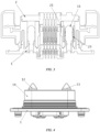
FIG. 2 is a schematic diagram showing a structure of the quick-swapping connector of the disclosure before the socket is in fit connection with a plug; -
FIG. 3 is a schematic diagram showing a structure of the quick-swapping connector of the disclosure after the socket is in fit connection with the plug; -
FIG. 4 is a schematic diagram (II) showing a structure of the socket of the quick-swapping connector of the disclosure; -
FIG. 5 is a schematic diagram showing a connection relationship and structure of a grounding positioning hole and a contact spring of the quick-swapping connector of the disclosure; and -
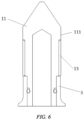
FIG. 6 is a schematic diagram showing a connection relationship and structure of a grounding positioning pin and a contact ring of the quick-swapping connector of the disclosure. - 1: socket; 11: grounding positioning pin; 111: second annular boss; 12: positioning pin; 13: contact ring; 14: annular bin wall; 15: positive terminal; 16: negative terminal; 2: plug; 21: grounding positioning hole; 211: annular protrusion; 212: first annular boss; 22: positioning hole; 23: contact spring; 231: annular groove; 3: annular stopper.
- Preferred implementations of the disclosure will be described below with reference to the accompanying drawings. Those skilled in the art should understand that these implementations are merely used to explain the technical principles of the disclosure, and are not intended to limit the scope of protection of the disclosure. Those skilled in the art can make adjustments to the implementations according to requirements, so as to adapt to specific application scenarios.
- It should be noted that in the description of the disclosure, the terms "first" and "second" are merely used for descriptive purposes and cannot be understood as indicating or implying relative importance.
- In addition, it should also be noted that, in the description of the disclosure, the terms "mount", "connection" and "connected" should be interpreted in a broad sense unless explicitly defined and limited otherwise, which, for example, may mean a fixed connection, a detachable connection or an integral connection; may be a mechanical connection or an electrical connection; or may be a direct connection, an indirect connection by means of an intermediary, or internal communication between two elements. For those skilled in the art, the specific meanings of the foregoing terms in the disclosure can be interpreted according to a specific situation.
- As shown in
FIGS. 1 to 3 , in order to solve the problems of the large size and heavy weight of an existing quick-swapping connector having an equipotential connection function, the disclosure provides a quick-swapping connector. The quick-swapping connector comprises asocket 1 and aplug 2, wherein agrounding positioning pin 11 is provided on thesocket 1, a first annular grounding structure is sleeved on the periphery of thegrounding positioning pin 11, agrounding positioning hole 21 is provided in theplug 2, a second grounding structure is connected in thegrounding positioning hole 21, thegrounding positioning pin 11 is insertable into thegrounding positioning hole 21 for positioning, and after the grounding positioningpin 11 is inserted into thegrounding positioning hole 21, the first grounding structure comes into contact with the second grounding structure. It will be understood that the grounding positioningpin 11 is in fit connection with thegrounding positioning hole 21, and the grounding positioningpin 11 can not only be inserted into thegrounding positioning hole 21, but can also be pulled out of thegrounding positioning hole 21. Thegrounding positioning pin 11 is suitable for connection to a battery, and thegrounding positioning hole 21 is suitable for connection to a vehicle body, thereby realizing grounding. - Preferably, the second grounding structure is a
contact spring 23, for example, one of a crown spring, a torsion spring, a spring contact finger and a wire spring. It will be understood that thecontact spring 23 is of an annular structure. In addition, it is only necessary for the first grounding structure to be annular and enable equipotential connection to thecontact spring 23, for example, acontact ring 13. After thegrounding positioning pin 11 is inserted into thegrounding positioning hole 21, an outer ring of thecontact ring 13 comes into contact with an inner ring of thecontact spring 23, so that the contact reliability is improved. - In addition, a
positioning pin 12 is also provided on thesocket 1, apositioning hole 22 is also provided in theplug 2, and thepositioning pin 12 is insertable into thepositioning hole 22 for positioning, so that thepositioning pin 12 can also be in fit connection with thepositioning hole 22 on the basis of thegrounding positioning pin 11 being in fit connection with thegrounding positioning hole 21, thereby realizing two-point positioning and improving the reliability of connection between thesocket 1 and theplug 2. It will be understood that thepositioning pin 12 can not only be inserted into thepositioning hole 22, but can also be pulled out of thepositioning hole 22. - For ease of description, in the following, the second grounding structure of the disclosure will be described by taking the
contact spring 23 as an example, and the first annular grounding structure will be described in the form of thecontact ring 13. - When the
socket 1 of the quick-swapping connector is in fit connection with theplug 2 thereof, thepositioning pin 12 is inserted into thepositioning hole 22 and thegrounding positioning pin 11 is inserted into thegrounding positioning hole 21, so that thecontact spring 23 and thecontact ring 13 come into contact with each other. The connection and positioning between thesocket 1 and theplug 2 of the quick-swapping connector are realized by means of the fit between thepositioning pin 12 and thepositioning hole 22 and between thegrounding positioning pin 11 and thegrounding positioning hole 21. In addition, an equipotential connection between thesocket 1 and theplug 2 is realized by means of the contact between thecontact ring 13 and thecontact spring 23. - Compared with the prior art, according to the disclosure, the
contact spring 23 is built in thegrounding positioning hole 21 and thecontact ring 13 is sleeved on the periphery of thegrounding positioning pin 11, so that such a grounding structure is built in thegrounding positioning hole 21 after thegrounding positioning pin 11 is inserted into thegrounding positioning hole 21, thereby improving the overall interface layout of an existing quick-swapping connector, saving on interface space of the quick-swapping connector, further miniaturizing the quick-swapping connector, reducing the number of components and parts, reducing the weight of the quick-swapping connector, improving material utilization, and reducing costs. In addition, by providing thecontact ring 13, it is possible to provide a stable contact relationship with thecontact spring 23, avoiding the occurrence of poor contact caused by a gap when thegrounding positioning pin 11 is in direct fit with thecontact spring 23. - Also, since the structural strength of the
grounding positioning pin 11 is higher than the structural strength of a conventional grounding terminal, the technical solution of the present disclosure in which thecontact ring 13 is integrated on thegrounding positioning pin 11 and thecontact spring 23 is internally connected to thegrounding positioning hole 21 can ensure that the grounding structure has a higher strength while ensuring reliable contact between thesocket 1 and theplug 2. - In addition, compared with a conventional solution, since the grounding structure of the quick-swapping connector of the disclosure is not external, when the
plug 2 is in fit connection with thesocket 1, contact points can be reduced, thereby effectively preventing mechanical collision between thecontact ring 13 and thecontact spring 23 during battery swapping. - There are various specific implementations for assembling the
contact spring 23 in thegrounding positioning hole 21. As shown inFIG. 5 , the disclosure will be described by taking the following possible implementations as examples. - First, the
contact spring 23 is connected to thegrounding positioning hole 21 in an interference fit manner. Second, anannular protrusion 211 is formed on an inner wall of thegrounding positioning hole 21, anannular groove 231 is formed on an outer wall of thecontact spring 23, and theannular protrusion 211 is adaptively mounted into theannular groove 231 to form limiting, thereby ensuring the stability of thecontact spring 23 in thegrounding positioning hole 21. Third, a firstannular boss 212 is formed on the inner wall of thegrounding positioning hole 21, for example, the firstannular boss 212 is located at a lower portion of the inner wall of thegrounding positioning hole 21, and a bottom end of thecontact spring 23 is carried on the firstannular boss 212, that is, the bottom end of thecontact spring 23 is carried on a contact surface of the firstannular boss 212 in an axial direction of thegrounding positioning hole 21, so as to prevent thecontact spring 23 from falling out of thegrounding positioning hole 21. It will be understood that the lower portion of the inner wall of thegrounding positioning hole 21 refers to a side of thegrounding positioning hole 21 close to the ground after theplug 2 is in fit connection with thesocket 1. Of course, the position of the firstannular boss 212 may also be appropriately adjusted according to the specific form and size of thecontact spring 23. For example, the firstannular boss 212 is located in the middle of the inner wall of thegrounding positioning hole 21, etc. - The above-described three implementations may be three independent implementations, or may be arbitrarily combined. For example, the quick-swapping connector of the disclosure has all the above-described three implementations.
- In addition, as a possible implementation, as shown in
FIG. 6 , the quick-swapping connector further comprises anannular stopper 3, theannular stopper 3 is detachably sleeved on the periphery of thegrounding positioning pin 11, a secondannular boss 111 is formed on an outer wall of thegrounding positioning pin 11, for example, the secondannular boss 111 is located at an upper portion of the outer wall of thegrounding positioning pin 11, and thecontact ring 13 is engaged between the secondannular boss 111 and theannular stopper 3. It will be understood that the upper portion of the outer wall of thegrounding positioning pin 11 refers to a side of thegrounding positioning pin 11 away from the ground after theplug 2 is in fit connection with thesocket 1. - There are various specific implementations for detachably sleeving the
annular stopper 3 on the periphery of thegrounding positioning pin 11. For example, an annular groove is formed on thegrounding positioning pin 11, a sealing ring is provided in the annular groove, theannular stopper 3 is fastened to thegrounding positioning pin 11 by means of the sealing ring, that is, the sealing ring is arranged between theannular stopper 3 and thegrounding positioning pin 11. Alternatively, theannular stopper 3 is connected to thegrounding positioning pin 11 by a means of a screw, etc. - When the second
annular boss 111 is located at the upper portion of the outer wall of thegrounding positioning pin 11, during assembly, thecontact ring 13 is first mounted from a lower portion of thegrounding positioning pin 11, theannular stopper 3 is then mounted, and theannular stopper 3 is fixed such that thecontact ring 13 is engaged between the secondannular boss 111 and theannular stopper 3, thereby forming fixation and limiting. Such an arrangement can facilitate the maintenance and replacement of thecontact ring 13 while ensuring the stability of thecontact ring 13. Of course, alternatively, the secondannular boss 111 may also be located at the lower portion of the outer wall of thegrounding positioning pin 11, and in this case, theannular stopper 3 is located at the upper portion of the outer wall of thegrounding positioning pin 11. These simple changes fall within the scope of protection of the disclosure. - As a preferred implementation, the
contact spring 23 and thecontact ring 13 are made of the same material. This can prevent chemical corrosion caused by contact between metals of different materials. For example, thecontact spring 23 and thecontact ring 13 are made of one of copper, nickel and zinc. - As a preferred implementation, as shown in
FIG. 4 and with reference toFIG. 1 , anannular bin wall 14 is provided on thesocket 1, thepositioning pin 12 and thegrounding positioning pin 11 are arranged inside of theannular bin wall 14, and after thepositioning pin 12 is inserted into thepositioning hole 22 and thegrounding positioning pin 11 is inserted into thegrounding positioning hole 21, thesocket 1, theannular bin wall 14 and theplug 2 enclose an electrical connection cavity (not shown), so that thegrounding positioning pin 11 and thepositioning pin 12 are located in the electrical connection cavity. In other words, theannular bin wall 14 protrudes from thesocket 1, theannular bin wall 14 and thesocket 1 jointly enclose an electrical connection bin, and thegrounding positioning pin 11 and thepositioning pin 12 are arranged inside of theannular bin wall 14, that is, thegrounding positioning pin 11 and thepositioning pin 12 are arranged in the electrical connection bin. After thepositioning pin 12 is inserted into thepositioning hole 22 and thegrounding positioning pin 11 is inserted into thegrounding positioning hole 21, theplug 2 is in fit connection with thesocket 1, the electrical connection bin and theplug 2 jointly form the electrical connection cavity, and in this case, thegrounding positioning pin 11 and thepositioning pin 12 are located in the electrical connection cavity. - There are various ways for the electrical connection bin and the
plug 2 to jointly form the electrical connection cavity. For example, a groove structure may be formed on theplug 2, thepositioning hole 22, and thegrounding positioning hole 21, etc. are arranged in the groove. After thepositioning pin 12 is inserted into thepositioning hole 22 and thegrounding positioning pin 11 is inserted into thegrounding positioning hole 21, theannular bin wall 14 is connected to an inner peripheral wall of the groove, so as to enclose the electrical connection cavity. Alternatively, after thepositioning pin 12 is inserted into thepositioning hole 22 and thegrounding positioning pin 11 is inserted into thegrounding positioning hole 21, theannular bin wall 14 exactly abuts against theplug 2, so as to enclose the electrical connection cavity, etc. - If the positioning pin and the grounding positioning pin are arranged outside of the annular bin wall, over the long-term use of the vehicle, a large amount of dust will accumulate between the annular bin wall and the positioning pin over time, the accumulated dust is difficult to clean and thus result in failure of battery swapping, and the entire interface structure is loose. Therefore, according to the disclosure, the
positioning pin 12 and thegrounding positioning pin 11 are arranged inside of theannular bin wall 14, so that thegrounding positioning pin 11 and thepositioning pin 12 are located in the electrical connection cavity after thepositioning pin 12 is inserted into thepositioning hole 22 and thegrounding positioning pin 11 is inserted into thegrounding positioning hole 21. Since the electrical connection cavity is a relatively closed environment, the problem of dust accumulation between thepositioning pin 12 and theannular bin wall 14 can be effectively solved, thereby improving the success rate of battery swapping, and improving the overall interface layout of the existing quick-swapping connector, while saving on interface space of the quick-swapping connector, further miniaturizing the quick-swapping connector, and improving material utilization. - Preferably, with reference to
FIG. 1 , apositive terminal 15 and anegative terminal 16 on thesocket 1 are arranged inside of theannular bin wall 14, so that thepositive terminal 15 and thenegative terminal 16 are located in the electrical connection cavity after thepositioning pin 12 is inserted into thepositioning hole 22 and thegrounding positioning pin 11 is inserted into thegrounding positioning hole 21, thereby preventing thepositive terminal 15 and the negative terminal 16 from being dirty and failing. - It should be noted that the foregoing implementations are merely used to explain the principles of the disclosure, and are not intended to limit the scope of protection of the disclosure. Those skilled in the art can adjust the foregoing implementations without departing from the principle of the disclosure, so that the disclosure is applicable to more specific application scenarios.
- For example, as an alternative implementation, although the second grounding structure of the disclosure is described in the form of the
contact spring 23, this is not intended to limit the scope of protection of the disclosure. As long as the equipotential connection between theplug 2 and thesocket 1 can be realized, the configuration thereof can be adjusted, for example, the second grounding structure may be an annular metal sheet, or an elastic piece, etc. These all do not deviate from the principle of the disclosure and fall within the scope of protection of the disclosure. - For example, as an alternative implementation, although the disclosure is described in such a manner that after the
grounding positioning pin 11 is inserted into thegrounding positioning hole 21, the outer ring of the first grounding structure comes into contact with the inner ring of the second grounding structure, this arrangement is not unique, for example, the first grounding structure abuts against the second grounding structure, etc. These all do not deviate from the principle of the disclosure and fall within the scope of protection of the disclosure. - For example, the
positioning pin 12 and thepositioning hole 22 may be omitted. - For example, as an alternative implementation, the specific arrangement of the
contact ring 13 sleeved on the periphery of thegrounding positioning pin 11 can be adjusted, for example, thecontact ring 13 is directly welded to thegrounding positioning pin 11, etc. These all do not deviate from the principle of the disclosure and fall within the scope of protection of the disclosure. - In another aspect, the disclosure further provides a vehicle, comprising a battery, a vehicle body and a quick-swapping connector of any one of the above-described implementations, wherein the socket is connected to the battery, and the plug is connected to the vehicle body.
- After the vehicle has the quick-swapping connector, it is possible to ensure reliable contact between the
socket 1 and theplug 2, reduce the number of components and parts, improve material utilization, reduce costs, and improve the success rate of battery swapping while realizing the equipotential connection between the quick-swappingplug 2 and the quick-swappingsocket 1 of the vehicle. - Heretofore, the technical solutions of the disclosure have been described with reference to the preferred implementations shown in the accompanying drawings. However, those skilled in the art can readily understand that the scope of protection of the disclosure is apparently not limited to these specific implementations. Without departing from the principles of the disclosure, those skilled in the art may make equivalent changes or replacements to related technical features. The technical solutions obtained after these changes or replacements fall within the scope of protection of the disclosure.
Claims (10)
- A quick-swapping connector, comprising:a socket, a grounding positioning pin being provided on the socket, and a first annular grounding structure being sleeved on the periphery of the grounding positioning pin; anda plug, a grounding positioning hole being provided in the plug, a second grounding structure being connected in the grounding positioning hole, the grounding positioning pin being insertable into the grounding positioning hole for positioning, and after the grounding positioning pin is inserted into the grounding positioning hole, the first grounding structure coming into contact with the second grounding structure.
- The quick-swapping connector according to claim 1, wherein the second grounding structure is a contact spring.
- The quick-swapping connector according to claim 2, wherein
the contact spring is connected to the grounding positioning hole in an interference fit manner. - The quick-swapping connector according to claim 2, whereinan annular protrusion is formed on an inner wall of the grounding positioning hole, an annular groove is formed on an outer wall of the contact spring, and the annular protrusion is adaptively mounted into the annular groove; and/ora first annular boss is formed on the inner wall of the grounding positioning hole, and a bottom end of the contact spring is carried on the first annular boss.
- The quick-swapping connector according to claim 1, further comprising:
an annular stopper, the annular stopper being detachably sleeved on the periphery of the grounding positioning pin, a second annular boss being formed on an outer wall of the grounding positioning pin, and the first grounding structure being engaged between the second annular boss and the annular stopper. - The quick-swapping connector according to claim 2, wherein
after the grounding positioning pin is inserted into the grounding positioning hole, an outer ring of the first grounding structure comes into contact with an inner ring of the second grounding structure. - The quick-swapping connector according to claim 1, wherein
the first grounding structure and the second grounding structure are made of the same material. - The quick-swapping connector according to claim 1, wherein
a positioning pin is also provided on the socket, a positioning hole is also provided in the plug, and the positioning pin is insertable into the positioning hole for positioning. - The quick-swapping connector according to claim 7, wherein
an annular bin wall is provided on the socket, the positioning pin and the grounding positioning pin are arranged inside of the annular bin wall, and after the positioning pin is inserted into the positioning hole and the grounding positioning pin is inserted into the grounding positioning hole, the socket, the annular bin wall and the plug enclose an electrical connection cavity. - A vehicle, comprising a quick-swapping connector of any one of claims 1 to 9, the vehicle further comprising a battery and a vehicle body, wherein the socket is connected to the battery, and the plug is connected to the vehicle body.
Applications Claiming Priority (2)
| Application Number | Priority Date | Filing Date | Title |
|---|---|---|---|
| CN202221095652.4U CN217444773U (en) | 2022-05-09 | 2022-05-09 | Quick-change connector and vehicle with same |
| PCT/CN2023/092860 WO2023217099A1 (en) | 2022-05-09 | 2023-05-09 | Quick-change connector and vehicle having same |
Publications (1)
| Publication Number | Publication Date |
|---|---|
| EP4525219A1 true EP4525219A1 (en) | 2025-03-19 |
Family
ID=83219210
Family Applications (1)
| Application Number | Title | Priority Date | Filing Date |
|---|---|---|---|
| EP23802869.0A Withdrawn EP4525219A1 (en) | 2022-05-09 | 2023-05-09 | Quick-change connector and vehicle having same |
Country Status (4)
| Country | Link |
|---|---|
| US (1) | US20250296456A1 (en) |
| EP (1) | EP4525219A1 (en) |
| CN (1) | CN217444773U (en) |
| WO (1) | WO2023217099A1 (en) |
Families Citing this family (2)
| Publication number | Priority date | Publication date | Assignee | Title |
|---|---|---|---|---|
| CN217444773U (en) * | 2022-05-09 | 2022-09-16 | 蔚来汽车科技(安徽)有限公司 | Quick-change connector and vehicle with same |
| CN221900262U (en) * | 2024-01-29 | 2024-10-25 | 蔚来电池科技(安徽)有限公司 | Plugs, electrical connectors, battery packs and electrical devices |
Family Cites Families (6)
| Publication number | Priority date | Publication date | Assignee | Title |
|---|---|---|---|---|
| TWM327118U (en) * | 2007-05-22 | 2008-02-11 | Insert Entpr Co Ltd | Super-miniature coaxial micro switch connector |
| CN201985360U (en) * | 2011-03-16 | 2011-09-21 | 南京普斯迪尔电子科技有限公司 | Device for guiding and positioning switching interface of battery pack |
| CN108767588A (en) * | 2018-07-02 | 2018-11-06 | 江苏亨通新能源电气技术有限公司 | Can fast quick change electricity change electric connector and the electric vehicle including it |
| CN211017587U (en) * | 2019-12-24 | 2020-07-14 | 华霆(合肥)动力技术有限公司 | Quick-change connector and battery replacement system |
| CN112909629A (en) * | 2021-03-08 | 2021-06-04 | 中航光电科技股份有限公司 | Shielding connector, plug and socket |
| CN217444773U (en) * | 2022-05-09 | 2022-09-16 | 蔚来汽车科技(安徽)有限公司 | Quick-change connector and vehicle with same |
-
2022
- 2022-05-09 CN CN202221095652.4U patent/CN217444773U/en active Active
-
2023
- 2023-05-09 EP EP23802869.0A patent/EP4525219A1/en not_active Withdrawn
- 2023-05-09 US US18/864,452 patent/US20250296456A1/en active Pending
- 2023-05-09 WO PCT/CN2023/092860 patent/WO2023217099A1/en not_active Ceased
Also Published As
| Publication number | Publication date |
|---|---|
| WO2023217099A1 (en) | 2023-11-16 |
| US20250296456A1 (en) | 2025-09-25 |
| CN217444773U (en) | 2022-09-16 |
Similar Documents
| Publication | Publication Date | Title |
|---|---|---|
| EP4525219A1 (en) | Quick-change connector and vehicle having same | |
| EP4535577A1 (en) | Positioning device and truck | |
| CN213340795U (en) | Female terminal, male terminal and connector | |
| CN110829100A (en) | Replacement connector | |
| CN218070150U (en) | Insulating part, end cover assembly, battery pack and electric equipment of battery | |
| CN210518026U (en) | Electronic water pump | |
| CN217334578U (en) | Connector socket and vehicle-mounted charger | |
| CN213073051U (en) | Anti-static discharge earphone | |
| CN214754075U (en) | Top cover structure of power battery and power battery | |
| CN213483905U (en) | Prevent apron structure under lithium cell that rocks | |
| CN218769984U (en) | Battery and electronic device | |
| CN111029868A (en) | An audio switching connector assembly | |
| CN214506617U (en) | Vehicle-mounted charger with display function | |
| CN214505835U (en) | A low-voltage communication connector and battery system | |
| WO2024212489A1 (en) | Pole core assembly, battery cell, battery pack and electric device | |
| CN211743515U (en) | Charging socket with protection mechanism | |
| CN211789840U (en) | An integrated plug-in structure | |
| CN210041912U (en) | Universal shaft wire guide type mobile phone support | |
| CN211184575U (en) | BMS shell | |
| CN210015995U (en) | Side-connected spring plate | |
| CN217215918U (en) | Elastic sheet type electromagnetic shielding joint | |
| CN219392474U (en) | Selenium drum structure and printer | |
| CN220456696U (en) | Vehicle charging assembly and energy storage power supply | |
| CN223260919U (en) | A replaceable power terminal charging gun with a safety anti-touch PIN | |
| CN223079495U (en) | Stable plug-in structure of connector |
Legal Events
| Date | Code | Title | Description |
|---|---|---|---|
| STAA | Information on the status of an ep patent application or granted ep patent |
Free format text: STATUS: THE INTERNATIONAL PUBLICATION HAS BEEN MADE |
|
| PUAI | Public reference made under article 153(3) epc to a published international application that has entered the european phase |
Free format text: ORIGINAL CODE: 0009012 |
|
| STAA | Information on the status of an ep patent application or granted ep patent |
Free format text: STATUS: REQUEST FOR EXAMINATION WAS MADE |
|
| 17P | Request for examination filed |
Effective date: 20241206 |
|
| AK | Designated contracting states |
Kind code of ref document: A1 Designated state(s): AL AT BE BG CH CY CZ DE DK EE ES FI FR GB GR HR HU IE IS IT LI LT LU LV MC ME MK MT NL NO PL PT RO RS SE SI SK SM TR |
|
| STAA | Information on the status of an ep patent application or granted ep patent |
Free format text: STATUS: THE APPLICATION HAS BEEN WITHDRAWN |
|
| DAV | Request for validation of the european patent (deleted) | ||
| DAX | Request for extension of the european patent (deleted) | ||
| 18W | Application withdrawn |
Effective date: 20250731 |