EP4525199A2 - Battery assembly and battery pack having the same - Google Patents
Battery assembly and battery pack having the same Download PDFInfo
- Publication number
- EP4525199A2 EP4525199A2 EP25154420.1A EP25154420A EP4525199A2 EP 4525199 A2 EP4525199 A2 EP 4525199A2 EP 25154420 A EP25154420 A EP 25154420A EP 4525199 A2 EP4525199 A2 EP 4525199A2
- Authority
- EP
- European Patent Office
- Prior art keywords
- battery
- cell
- cell stack
- plate
- assembly
- Prior art date
- Legal status (The legal status is an assumption and is not a legal conclusion. Google has not performed a legal analysis and makes no representation as to the accuracy of the status listed.)
- Pending
Links
Images




Classifications
-
- H—ELECTRICITY
- H01—ELECTRIC ELEMENTS
- H01M—PROCESSES OR MEANS, e.g. BATTERIES, FOR THE DIRECT CONVERSION OF CHEMICAL ENERGY INTO ELECTRICAL ENERGY
- H01M10/00—Secondary cells; Manufacture thereof
- H01M10/42—Methods or arrangements for servicing or maintenance of secondary cells or secondary half-cells
- H01M10/425—Structural combination with electronic components, e.g. electronic circuits integrated to the outside of the casing
-
- H—ELECTRICITY
- H01—ELECTRIC ELEMENTS
- H01M—PROCESSES OR MEANS, e.g. BATTERIES, FOR THE DIRECT CONVERSION OF CHEMICAL ENERGY INTO ELECTRICAL ENERGY
- H01M10/00—Secondary cells; Manufacture thereof
- H01M10/42—Methods or arrangements for servicing or maintenance of secondary cells or secondary half-cells
- H01M10/48—Accumulators combined with arrangements for measuring, testing or indicating the condition of cells, e.g. the level or density of the electrolyte
- H01M10/482—Accumulators combined with arrangements for measuring, testing or indicating the condition of cells, e.g. the level or density of the electrolyte for several batteries or cells simultaneously or sequentially
-
- H—ELECTRICITY
- H01—ELECTRIC ELEMENTS
- H01M—PROCESSES OR MEANS, e.g. BATTERIES, FOR THE DIRECT CONVERSION OF CHEMICAL ENERGY INTO ELECTRICAL ENERGY
- H01M50/00—Constructional details or processes of manufacture of the non-active parts of electrochemical cells other than fuel cells, e.g. hybrid cells
- H01M50/20—Mountings; Secondary casings or frames; Racks, modules or packs; Suspension devices; Shock absorbers; Transport or carrying devices; Holders
- H01M50/204—Racks, modules or packs for multiple batteries or multiple cells
- H01M50/207—Racks, modules or packs for multiple batteries or multiple cells characterised by their shape
- H01M50/211—Racks, modules or packs for multiple batteries or multiple cells characterised by their shape adapted for pouch cells
-
- H—ELECTRICITY
- H01—ELECTRIC ELEMENTS
- H01M—PROCESSES OR MEANS, e.g. BATTERIES, FOR THE DIRECT CONVERSION OF CHEMICAL ENERGY INTO ELECTRICAL ENERGY
- H01M50/00—Constructional details or processes of manufacture of the non-active parts of electrochemical cells other than fuel cells, e.g. hybrid cells
- H01M50/20—Mountings; Secondary casings or frames; Racks, modules or packs; Suspension devices; Shock absorbers; Transport or carrying devices; Holders
- H01M50/218—Mountings; Secondary casings or frames; Racks, modules or packs; Suspension devices; Shock absorbers; Transport or carrying devices; Holders characterised by the material
- H01M50/22—Mountings; Secondary casings or frames; Racks, modules or packs; Suspension devices; Shock absorbers; Transport or carrying devices; Holders characterised by the material of the casings or racks
- H01M50/222—Inorganic material
-
- H—ELECTRICITY
- H01—ELECTRIC ELEMENTS
- H01M—PROCESSES OR MEANS, e.g. BATTERIES, FOR THE DIRECT CONVERSION OF CHEMICAL ENERGY INTO ELECTRICAL ENERGY
- H01M50/00—Constructional details or processes of manufacture of the non-active parts of electrochemical cells other than fuel cells, e.g. hybrid cells
- H01M50/20—Mountings; Secondary casings or frames; Racks, modules or packs; Suspension devices; Shock absorbers; Transport or carrying devices; Holders
- H01M50/218—Mountings; Secondary casings or frames; Racks, modules or packs; Suspension devices; Shock absorbers; Transport or carrying devices; Holders characterised by the material
- H01M50/22—Mountings; Secondary casings or frames; Racks, modules or packs; Suspension devices; Shock absorbers; Transport or carrying devices; Holders characterised by the material of the casings or racks
- H01M50/227—Organic material
-
- H—ELECTRICITY
- H01—ELECTRIC ELEMENTS
- H01M—PROCESSES OR MEANS, e.g. BATTERIES, FOR THE DIRECT CONVERSION OF CHEMICAL ENERGY INTO ELECTRICAL ENERGY
- H01M50/00—Constructional details or processes of manufacture of the non-active parts of electrochemical cells other than fuel cells, e.g. hybrid cells
- H01M50/20—Mountings; Secondary casings or frames; Racks, modules or packs; Suspension devices; Shock absorbers; Transport or carrying devices; Holders
- H01M50/218—Mountings; Secondary casings or frames; Racks, modules or packs; Suspension devices; Shock absorbers; Transport or carrying devices; Holders characterised by the material
- H01M50/22—Mountings; Secondary casings or frames; Racks, modules or packs; Suspension devices; Shock absorbers; Transport or carrying devices; Holders characterised by the material of the casings or racks
- H01M50/229—Composite material consisting of a mixture of organic and inorganic materials
-
- H—ELECTRICITY
- H01—ELECTRIC ELEMENTS
- H01M—PROCESSES OR MEANS, e.g. BATTERIES, FOR THE DIRECT CONVERSION OF CHEMICAL ENERGY INTO ELECTRICAL ENERGY
- H01M50/00—Constructional details or processes of manufacture of the non-active parts of electrochemical cells other than fuel cells, e.g. hybrid cells
- H01M50/20—Mountings; Secondary casings or frames; Racks, modules or packs; Suspension devices; Shock absorbers; Transport or carrying devices; Holders
- H01M50/249—Mountings; Secondary casings or frames; Racks, modules or packs; Suspension devices; Shock absorbers; Transport or carrying devices; Holders specially adapted for aircraft or vehicles, e.g. cars or trains
-
- H—ELECTRICITY
- H01—ELECTRIC ELEMENTS
- H01M—PROCESSES OR MEANS, e.g. BATTERIES, FOR THE DIRECT CONVERSION OF CHEMICAL ENERGY INTO ELECTRICAL ENERGY
- H01M50/00—Constructional details or processes of manufacture of the non-active parts of electrochemical cells other than fuel cells, e.g. hybrid cells
- H01M50/20—Mountings; Secondary casings or frames; Racks, modules or packs; Suspension devices; Shock absorbers; Transport or carrying devices; Holders
- H01M50/258—Modular batteries; Casings provided with means for assembling
-
- H—ELECTRICITY
- H01—ELECTRIC ELEMENTS
- H01M—PROCESSES OR MEANS, e.g. BATTERIES, FOR THE DIRECT CONVERSION OF CHEMICAL ENERGY INTO ELECTRICAL ENERGY
- H01M50/00—Constructional details or processes of manufacture of the non-active parts of electrochemical cells other than fuel cells, e.g. hybrid cells
- H01M50/20—Mountings; Secondary casings or frames; Racks, modules or packs; Suspension devices; Shock absorbers; Transport or carrying devices; Holders
- H01M50/262—Mountings; Secondary casings or frames; Racks, modules or packs; Suspension devices; Shock absorbers; Transport or carrying devices; Holders with fastening means, e.g. locks
- H01M50/264—Mountings; Secondary casings or frames; Racks, modules or packs; Suspension devices; Shock absorbers; Transport or carrying devices; Holders with fastening means, e.g. locks for cells or batteries, e.g. straps, tie rods or peripheral frames
-
- H—ELECTRICITY
- H01—ELECTRIC ELEMENTS
- H01M—PROCESSES OR MEANS, e.g. BATTERIES, FOR THE DIRECT CONVERSION OF CHEMICAL ENERGY INTO ELECTRICAL ENERGY
- H01M50/00—Constructional details or processes of manufacture of the non-active parts of electrochemical cells other than fuel cells, e.g. hybrid cells
- H01M50/20—Mountings; Secondary casings or frames; Racks, modules or packs; Suspension devices; Shock absorbers; Transport or carrying devices; Holders
- H01M50/284—Mountings; Secondary casings or frames; Racks, modules or packs; Suspension devices; Shock absorbers; Transport or carrying devices; Holders with incorporated circuit boards, e.g. printed circuit boards [PCB]
-
- H—ELECTRICITY
- H01—ELECTRIC ELEMENTS
- H01M—PROCESSES OR MEANS, e.g. BATTERIES, FOR THE DIRECT CONVERSION OF CHEMICAL ENERGY INTO ELECTRICAL ENERGY
- H01M50/00—Constructional details or processes of manufacture of the non-active parts of electrochemical cells other than fuel cells, e.g. hybrid cells
- H01M50/50—Current conducting connections for cells or batteries
- H01M50/502—Interconnectors for connecting terminals of adjacent batteries; Interconnectors for connecting cells outside a battery casing
- H01M50/507—Interconnectors for connecting terminals of adjacent batteries; Interconnectors for connecting cells outside a battery casing comprising an arrangement of two or more busbars within a container structure, e.g. busbar modules
-
- H—ELECTRICITY
- H01—ELECTRIC ELEMENTS
- H01M—PROCESSES OR MEANS, e.g. BATTERIES, FOR THE DIRECT CONVERSION OF CHEMICAL ENERGY INTO ELECTRICAL ENERGY
- H01M50/00—Constructional details or processes of manufacture of the non-active parts of electrochemical cells other than fuel cells, e.g. hybrid cells
- H01M50/50—Current conducting connections for cells or batteries
- H01M50/502—Interconnectors for connecting terminals of adjacent batteries; Interconnectors for connecting cells outside a battery casing
- H01M50/519—Interconnectors for connecting terminals of adjacent batteries; Interconnectors for connecting cells outside a battery casing comprising printed circuit boards [PCB]
-
- H—ELECTRICITY
- H01—ELECTRIC ELEMENTS
- H01M—PROCESSES OR MEANS, e.g. BATTERIES, FOR THE DIRECT CONVERSION OF CHEMICAL ENERGY INTO ELECTRICAL ENERGY
- H01M50/00—Constructional details or processes of manufacture of the non-active parts of electrochemical cells other than fuel cells, e.g. hybrid cells
- H01M50/50—Current conducting connections for cells or batteries
- H01M50/543—Terminals
- H01M50/547—Terminals characterised by the disposition of the terminals on the cells
- H01M50/548—Terminals characterised by the disposition of the terminals on the cells on opposite sides of the cell
-
- H—ELECTRICITY
- H01—ELECTRIC ELEMENTS
- H01M—PROCESSES OR MEANS, e.g. BATTERIES, FOR THE DIRECT CONVERSION OF CHEMICAL ENERGY INTO ELECTRICAL ENERGY
- H01M50/00—Constructional details or processes of manufacture of the non-active parts of electrochemical cells other than fuel cells, e.g. hybrid cells
- H01M50/50—Current conducting connections for cells or batteries
- H01M50/543—Terminals
- H01M50/552—Terminals characterised by their shape
- H01M50/553—Terminals adapted for prismatic, pouch or rectangular cells
- H01M50/557—Plate-shaped terminals
-
- H—ELECTRICITY
- H01—ELECTRIC ELEMENTS
- H01M—PROCESSES OR MEANS, e.g. BATTERIES, FOR THE DIRECT CONVERSION OF CHEMICAL ENERGY INTO ELECTRICAL ENERGY
- H01M50/00—Constructional details or processes of manufacture of the non-active parts of electrochemical cells other than fuel cells, e.g. hybrid cells
- H01M50/50—Current conducting connections for cells or batteries
- H01M50/569—Constructional details of current conducting connections for detecting conditions inside cells or batteries, e.g. details of voltage sensing terminals
-
- H—ELECTRICITY
- H01—ELECTRIC ELEMENTS
- H01M—PROCESSES OR MEANS, e.g. BATTERIES, FOR THE DIRECT CONVERSION OF CHEMICAL ENERGY INTO ELECTRICAL ENERGY
- H01M10/00—Secondary cells; Manufacture thereof
- H01M10/42—Methods or arrangements for servicing or maintenance of secondary cells or secondary half-cells
- H01M10/425—Structural combination with electronic components, e.g. electronic circuits integrated to the outside of the casing
- H01M2010/4271—Battery management systems including electronic circuits, e.g. control of current or voltage to keep battery in healthy state, cell balancing
-
- H—ELECTRICITY
- H01—ELECTRIC ELEMENTS
- H01M—PROCESSES OR MEANS, e.g. BATTERIES, FOR THE DIRECT CONVERSION OF CHEMICAL ENERGY INTO ELECTRICAL ENERGY
- H01M2220/00—Batteries for particular applications
- H01M2220/20—Batteries in motive systems, e.g. vehicle, ship, plane
-
- Y—GENERAL TAGGING OF NEW TECHNOLOGICAL DEVELOPMENTS; GENERAL TAGGING OF CROSS-SECTIONAL TECHNOLOGIES SPANNING OVER SEVERAL SECTIONS OF THE IPC; TECHNICAL SUBJECTS COVERED BY FORMER USPC CROSS-REFERENCE ART COLLECTIONS [XRACs] AND DIGESTS
- Y02—TECHNOLOGIES OR APPLICATIONS FOR MITIGATION OR ADAPTATION AGAINST CLIMATE CHANGE
- Y02E—REDUCTION OF GREENHOUSE GAS [GHG] EMISSIONS, RELATED TO ENERGY GENERATION, TRANSMISSION OR DISTRIBUTION
- Y02E60/00—Enabling technologies; Technologies with a potential or indirect contribution to GHG emissions mitigation
- Y02E60/10—Energy storage using batteries
Definitions
- the present disclosure relates to a battery assembly including a cell stack in which a plurality of battery cells are stacked, and a battery pack having the same.
- secondary batteries may be charged and discharged, and therefore, may be applied to devices within various fields such as digital cameras, mobile phones, notebook computers, hybrid vehicles, and electric vehicles.
- secondary batteries many studies are being conducted on lithium secondary batteries having high energy density and discharge voltage.
- the lithium secondary battery is manufactured as a pouch-type battery cell having flexibility, a prismatic or a cylindrical type battery cell having rigidity.
- a plurality of battery cells are electrically connected to form a stacked cell stack, and a battery module is formed by accommodating the cell stack in the module housing.
- the plurality of battery modules are accommodated in the pack housing to form a battery pack.
- the battery pack is installed and used in electric vehicles and the like.
- Each battery module accommodated in the battery pack includes a sensing unit to measure the voltage or temperature of the battery cells accommodated therein.
- the sensing unit includes a voltage sensing terminal, a temperature sensor, and a circuit member such as a wire for connecting the voltage sensing terminal or the temperature sensor.
- the battery module according to the related art is provided with a separate insulating plate formed of a plastic injection molding to support and install the wire, and the insulation between the wire and the battery cell is implemented through the insulating plate. For this reason, the battery module according to the related art has a problem in that the installation structure of the sensing unit is complicated and the overall volume is increased.
- the sensing unit provided in the battery module is coupled to a cell monitoring unit (CMU), and the cell monitoring unit measures the temperature, voltage, and chemical state of the battery module and transmits the measured results to the Battery Management System (BMS).
- CMU cell monitoring unit
- BMS Battery Management System
- the cell monitoring unit is spaced apart from the battery module and installed in a separate space provided inside the pack housing, and therefore, there may be a problem in which the space utilization inside the pack housing is lowered and the energy density of the battery pack is lowered.
- the battery pack according to the related art accommodates a plurality of battery modules. Since each battery module has a shape covering the entire exterior surface including the upper and lower surfaces of the cell stack and the space occupied by the battery module inside the pack housing thus increases, there is a disadvantage in that energy density is lowered.
- An aspect of the present disclosure is to provide a battery assembly in which space utilization may be increased and energy density may be improved when assembled as a battery pack, and a battery pack having the same.
- An aspect of the present disclosure is to provide a battery assembly in which installation of a sensing member may be facilitated and insulation between the sensing member and a battery cell may be secured, and a battery pack having the same.
- a battery assembly includes a cell stack in which a plurality of battery cells are stacked; a busbar assembly provided with a busbar electrically connected to an electrode lead of the battery cell, and coupled to the cell stack; a plate unit configured to cover at least a portion of a side surface of the cell stack; a sensing unit coupled to the busbar assembly and disposed outside of the cell stack; and a cell monitoring unit coupled to the sensing unit.
- the cell monitoring unit is installed on the plate unit.
- the sensing unit may include a circuit member disposed on one surface of the cell stack, and an insulating member coupled to the circuit member to insulate between the circuit member and the cell stack.
- the circuit member may include a flexible printed circuit board (FPCB), and the insulating member may include an insulating film or an insulating pad on which the flexible printed circuit board is installed.
- FPCB flexible printed circuit board
- the sensing unit may further include a sensor installed on an extension portion extending from the circuit member toward the busbar.
- the busbar assembly may further include an insulating support plate on which the busbar is installed, and an installation groove through which the extension portion passes may be disposed in the support plate.
- At least a portion of the cell stack and the sensing unit may be exposed to an outside of the plate unit.
- the plate unit may include a first plate covering the cell stack in a longitudinal direction of the battery cell, and a second plate covering the cell stack in a stacking direction of the battery cell.
- the plate unit may have a shape, surrounding four side surfaces of the cell stack and in which at least a portion of an upper surface and at least a portion of a lower surface of the cell stack are exposed externally.
- the busbar assembly may be disposed between the first plate and the cell stack.
- the battery cell may be formed of a pouch-type secondary battery provided with the electrode lead on both ends of the battery cell in the longitudinal direction, and the busbar assembly may be disposed on both ends of the battery cell in the longitudinal direction.
- the battery assembly may further include a bracket member coupled to an exterior surface of the plate unit.
- a battery pack includes a pack housing; and a plurality of battery assemblies accommodated in the pack housing.
- the battery assembly includes a cell stack in which a plurality of battery cells are stacked, a busbar assembly having a busbar electrically connected to the battery cell and coupled to the cell stack, a plate unit configured to cover at least a portion of a side surface of the cell stack, a sensing unit coupled to the busbar assembly and disposed outside of the cell stack, a cell monitoring unit coupled to the sensing unit and installed on the plate unit, and a bracket member coupled to an exterior surface of the plate unit, and the battery assembly is fixed to the pack housing by the bracket member.
- the plate unit may include a first plate covering the cell stack in a longitudinal direction of the battery cell, and the bracket member may be coupled to an exterior surface of the first plate.
- the pack housing may include a bottom portion, a sidewall portion extending upwardly from the bottom portion, and a cover portion covering a space formed by the bottom portion and the sidewall portion
- the bracket member may include a support plate facing the first plate, and an upper flange portion provided on an upper end of the support plate. The upper flange portion may be fastened to the side wall portion.
- the bracket member may be provided with a lower flange portion provided on a lower end of the support plate, and the lower flange portion may be fixed to the bottom portion.
- the bracket member may be provided with a lower flange portion provided on a lower end of the support plate, and the lower flange portion may extend in a direction of the cell stack to support a portion of a lower surface of the cell stack.
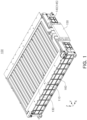
- FIG. 1 is a perspective view of the battery assembly 100 according to an embodiment
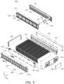
- FIG. 2 is an exploded perspective view of the battery assembly 100 illustrated in FIG. 1
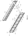
- FIG. 3 is a perspective view illustrating a state in which a busbar assembly 120 and a sensing unit 130 illustrated in FIG. 2 are combined.
- the battery assembly 100 may include a cell stack 110 in which a plurality of battery cells 111 are stacked, the busbar assembly 120 coupled to the cell stack 110, a plate unit 140 configured to cover at least a portion of a side surface of the cell stack 110, the sensing unit 130 connected to the busbar assembly 120, and a cell monitoring unit 150.
- the battery assembly 100 may include a bracket member 160 coupled to the exterior surface of the plate unit 140.
- the cell stack 110 forms a state in which the plurality of battery cells 111 are stacked.
- the battery cells 111 are stacked in such a manner that relatively wide surfaces are in contact with each other, and the neighboring battery cells 111 may be fixed through double-sided tape.
- the cell stacks 110 may be stacked in the horizontal direction (X) while the wide surfaces of the battery cells 111 are in contact, but the stacking direction is not limited thereto.
- the battery cells 111 provided in the cell stack 110 may be formed of a pouch-type secondary battery.
- the battery cell 111 formed of a pouch-type secondary battery may be configured in a form in which an electrode assembly and an electrolyte are accommodated in a casing (pouch).
- the electrode assembly may be configured in a form in which the positive and negative electrode plates are stacked with a separator interposed therebetween while the wide surfaces of the positive and negative plates face each other.
- An electrode tab is connected to the positive electrode plate and the negative electrode plate, respectively, and the electrode tabs having the same polarity are connected to electrode leads 112 to be exposed to the outside of the casing.
- the electrode leads 112 may be respectively disposed one both ends of the battery cell 111 in the longitudinal direction (Y), or a plurality of electrode leads 112 may also be located with different heights from each other on one end of the battery cell 111.
- the battery cell 111 may be formed of a lithium ion (Li-ion) battery or nickel metal hydride (Ni-MH) battery capable of charging and discharging.
- Li-ion lithium ion
- Ni-MH nickel metal hydride
- the battery cell 111 provided in the battery assembly 100 in an embodiment is not limited to the aforementioned pouch-type secondary battery, and for example, may also be configured as a can-type secondary battery.
- the can-type secondary battery may have a rectangular cross-section to be stacked to form the cell stack 110.
- the busbar assembly 120 may include a busbar 125 electrically connected to the electrode lead 112 of the battery cell 111, and may be coupled to the cell stack 110.
- the busbar 125 is formed of an electrically conductive material to implement a series and parallel electrical connection structure of the battery cells 111.
- the electrode lead 112 may be exposed to the outside of the busbar 125 through a coupling hole 126 formed by penetrating through the busbar 125.
- the electrode lead 112 may be welded to the busbar 125 while passing through the coupling hole 126.
- the busbar assembly 120 may include an insulating support plate 121 on which the busbar 125 is supported and installed, for insulation between busbars 125.
- the support plate 121 may be positioned between the busbar 125 and the battery cell 111 for insulation between the busbar 125 and the battery cell 111.
- the support plate 121 may have a through-hole 122 through which the electrode lead 112 may pass.
- the electrode lead 112 may be coupled to the coupling hole 126 of the busbar 125 while passing through the through-hole 122 of the support plate 121, and the busbar assembly 120 may have a state coupled to the cell stack 110.
- the plate unit 140 is configured to cover at least a portion of the side surface of the cell stack 110 to protect the side surface of the cell stack 110 from the outside.
- the plate unit 140 surrounds four side surfaces of the cell stack 110, and may have a shape such that at least a portion of an upper surface and at least a portion of a lower surface of the cell stack 110 are exposed externally. Also, as will be described later, at least a portion of the sensing unit 130 may have a structure exposed to the outside of the plate unit 140.
- the plate unit 140 may be provided with a first plate 141 covering the cell stack 110 in the longitudinal direction Y of the battery cell 111, and a second plate 145 covering the cell stack 110 in the stacking direction X of the battery cells 111.
- the busbar assembly 120 may be positioned between the first plate 141 and the cell stack 110.
- the first plate 141 may serve to protect the busbar assembly 120.
- at least portions of the first plate 141 and the second plate 145, the first plate 141 and the busbar assembly 120, and the second plate 145 and the busbar assembly 120 may be fastened to each other by known fastening means such as bolts.
- the second plate 145 may be configured to be coupled to the busbar assembly 120 to maintain a gap (e.g., a gap in the Y direction) between the cell stack 110 and the busbar assembly 120, and accordingly, a stable coupling between the electrode lead 112 of the battery cell 111 and the busbar 125 may be maintained.
- a gap e.g., a gap in the Y direction
- the first plate 141, the second plate 145, and the busbar assembly 120 may have assembly holes (reference numerals not provided) for fastening or penetrating the fastening means. In this manner, by the coupling between the cell stack 110 and the busbar assembly 120 and mutual coupling of the first plate 141, the second plate 145 and/or the busbar assembly 120, the battery assembly 100 may maintain an overall coupled state.
- the plate unit 140 is configured to cover side surfaces (both side surfaces of the cell stack 110 in the X direction in FIG. 2 ) of the cell stack 110, on which the busbar assembly 120 is not provided, and may not be installed on side surfaces (both side surfaces of the cell stack 110 in the Y direction in FIG. 2 ) on which the busbar assembly 120 is provided.
- two side surfaces of the battery cells 111 in the stacking direction X have a structure covered by the plate unit 140
- two side surfaces of the battery cell 111 in the longitudinal direction Y may have a structure covered by the busbar assembly 120.
- it may be modified to have a structure in which the four side surfaces of the cell stack 110 are protected by being surrounded by the plate unit 140 and the busbar assembly 120.
- a vent hole 142 may be formed in the first plate 141 to discharge gas, flames, combustion material, or the like discharged from the battery cell 111 outwardly of the cell stack 110.
- the battery cell 111 has a structure in which a sealing portion (not illustrated) is formed by sealing at least a portion of the periphery of the casing for accommodating the electrode assembly, and the sealing portion is folded to maintain sealing force.
- the sealing portion provided with the electrode lead 112 cannot be folded and may thus have the sealing force weaker than that of the folded portion.
- gas, flame, combustion materials, or the like may be discharged through the provided sealing portion on which the electrode lead 112 is disposed.
- gas, flame, combustion materials, or the like discharged from the cell stack 110 may be quickly discharged outwardly of the cell stack 110.
- the first plate 141 may be provided with a terminal connection portion 143 in which a connection terminal (127 in FIG. 3 ) electrically connected to the busbar 125 is installed.
- the terminal connection portion 143 may be installed on both ends of the battery assembly 100 in the long side direction. Accordingly, by configuring the connection path of the external busbar (not illustrated) interconnecting the battery assemblies 100 to be relatively short, the weight of the external busbar and/or reduce the installation costs thereof may be reduced.
- the sensing unit 130 is provided to measure the voltage or temperature of the battery cell 111.
- the sensing unit 130 may include a voltage sensing terminal 132 connected to the busbar 125 to measure the voltage of the battery cell 111, and a temperature sensor (not illustrated) installed on the exterior surface (e.g., upper surface) of the battery cell 111 to measure the temperature of the battery cell 111.
- the sensing unit 130 may include a circuit member 131 to provide a signal received from the voltage sensing terminal 132, the temperature sensor, and the like.
- the circuit member 131 may be formed of a printed circuit board (PCB), but may include a flexible printed circuit board (FPCB) for ease of handling and installation, and reduction in thickness.
- PCB printed circuit board
- FPCB flexible printed circuit board
- the circuit member 131 may be disposed on one surface of the cell stack 110, for example, an upper surface of the cell stack 110.
- the sensing unit 130 may further include an insulating member 135 coupled to the circuit member 131 to insulate between the circuit member 131 and the cell stack 110.
- the insulating member 135 may include an insulating film or an insulating pad on which a flexible printed circuit board is installed.
- the circuit member 131 formed of a flexible printed circuit board or a printed circuit board has a structure in which a circuit is formed on an insulating part. Since the circuit member 131 has a structure exposed to the outside of the plate unit 140, insulation may be insufficient during installation and use thereof. However, in an embodiment, after separately coupling the insulating member 135 to the circuit member 131, the insulating member 135 is positioned between the circuit member 131 and the cell stack 110, thereby improving the insulation performance of the sensing unit 130.
- the voltage sensing terminal 132 is attached to the busbar 125 through welding or the like.
- the sensing unit 130 may include an extension portion 131a extending from the circuit member 131 toward the busbar 125.
- the extension portion 131a may extend toward the busbar 125 through an installation groove formed in the support plate 121, and the voltage sensing terminal 132 may be installed on an end of the extension portion 131a.
- the extension portion 131a may extend from the circuit member 131 toward the upper surface of the cell stack 110, and a temperature sensor (not illustrated) may be installed on the extension portion 131a extending toward the upper surface of the cell stack 110.
- the sensing unit 130 since the sensing unit 130 has a structure connected to the busbar assembly 120, handling and installation may be easy, and the insulating performance between the cell stack 110 and the circuit member 131 may be improved through the insulating member 135 formed of an insulating film or an insulating pad.
- the installation structure of the sensing unit 130 is relatively simple and the volume is reduced.
- the cell monitoring unit 150 is connected to the sensing unit 130, and transmit the temperature and voltage measured in the battery module to a Battery Management System (BMS), based on information received from the voltage sensing terminal 132 and/or the temperature sensor, or the like.
- BMS Battery Management System
- the cell monitoring unit 150 may be installed on the plate unit 140.
- a mounting groove 146 for installation of the cell monitoring unit 150 may be formed in the second plate 145, and the cell monitoring unit 150 may be installed in the mounting groove 146 of the second plate 145 while being connected to a connector 133 of the sensing unit 130.
- the cell monitoring unit 150 is installed directly on the plate unit 140 configured to protect the cell stack 110. Therefore, according to an embodiment of the present disclosure, the advantage that the space utilization of a battery pack (200 in FIG. 4 ) may increase and energy density may be improved may be obtained, compared to the related art in which the cell monitoring unit is spaced apart from the battery module and installed in a separate space provided inside the battery pack.
- the battery assembly 100 may further include a bracket member 160 coupled to an exterior surface of the plate unit 140.
- the battery assembly 100 may be fixedly installed inside a pack housing (210 in FIG. 4 ) through the bracket member 160.
- the bracket member 160 may be installed to correspond to all side surfaces of the cell stack 110, but may be installed in a portion of the plate unit 140 to significantly reduce the volume of the battery assembly 100 and improve assembly.
- the bracket member 160 may have a structure coupled to the exterior surface of the first plate 141 corresponding to the long side of the cell stack 110.
- the first plate 141 is positioned between the bracket member 160 and the busbar assembly 120, and the bracket member 160 may be fastened to the busbar assembly 120.
- a through-hole through which a fastening member such as a bolt passes may be formed in the first plate 141.
- the bracket member 160 may also be provided with a support plate 161 formed as a wide surface facing the first plate 141, and an upper flange portion 162 provided on the upper end of the support plate 161.
- the bracket member 160 may be provided with a lower flange portion 163 provided on the lower end of the support plate 161.
- An opening 161a may be formed in the bracket member 160 to correspond to the vent hole 142 and/or the terminal connection portion 143 provided in the first plate 141. Accordingly, the gas, flame, and/or combustion material discharged through the vent hole 142 may be discharged to the outside of the battery assembly 100 through the opening 161a. Also, the terminal connection portion 143 may be exposed to the outside of the bracket member 160 through the opening 161a. The shape or number of the openings 161a may be variously changed.
- the battery pack 200 illustrated in FIGS. 4 to 9 may include the battery assembly 100 described with reference to FIGS. 1 to 3 . Therefore, to avoid unnecessary duplication, the description of the battery assembly 100 is replaced with the contents described with reference to FIGS. 1 to 3 , and a part related to the battery pack 200 will be mainly described.
- FIG. 4 is a perspective view of the battery pack 200 having the battery assembly 100 illustrated in FIG. 1 , and illustrates a state in which a cover portion (213 in FIGS. 7 and 8 ) of the pack housing 210 is omitted to check the internal structure.
- the battery pack 200 may include the pack housing 210 and a plurality of battery assemblies 100 accommodated in the pack housing 210.
- the pack housing 210 may include a side wall portion 212.
- the side wall portion 212 may include first sidewalls 212a positioned on both ends of the pack housing 210 in the first direction, and second sidewalls 212b positioned on both ends of the pack housing 210 in the second direction perpendicular to the first direction.
- the first sidewalls 212a and the second sidewalls 212b form four exterior surfaces of the pack housing 210.
- a partition member 220 may be provided inside the pack housing 210.
- the partition member 220 divides the space of the pack housing 210 into a plurality of spaces in which the battery assembly 100 is accommodated, respectively.
- the battery assembly 100 is installed in a space partitioned by the side wall portion 212 and the partition member 220, and the sensing unit 130 may have a state in which at least a portion is exposed to the outside of the battery assembly 100.
- the plurality of battery assemblies 100 may be electrically connected through an external busbar (not illustrated), and the external busbar may be connected to the terminal connection portion 143 of the battery assembly 100.
- the terminal connection portions 143 of the adjacent battery assemblies 100 may be disposed on positions corresponding to each other. Accordingly, the weight of the external busbar may be reduced and/or the installation costs may be reduced.
- the terminal connection portion 143 may be installed on both ends of the battery assembly 100 in the long side direction.
- a vent member 230 may be installed to discharge gas, flame, and/or combustion materials generated from the battery cells 111 constituting the cell stack 110 to the outside of the battery pack 200.
- the vent member 230 may have a structure that is normally closed and may be opened when gas is discharged. However, the vent member 230 may be configured as an open hole formed in the pack housing 210.
- a gas discharge path BP may be formed inside the pack housing 210 such that gas, flame, and/or combustion materials may move toward the vent member 230 and be discharged externally. The installation position and number of the vent member 230 may be variously changed.
- FIG. 5 is a perspective view illustrating a state in which the battery assembly 100 illustrated in FIG. 1 is mounted in the pack housing 210 illustrated in FIG. 4 , and illustrates a state in which the side wall portion 212 has been removed in order to check the internal structure.
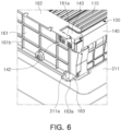
- FIG. 6 is an enlarged perspective view of the battery assembly 100 mounted in the pack housing 210 in FIG. 5 .
- the battery assembly 100 is installed in the space partitioned by the partition member 220 in the vertical direction, and may be fixed to a bottom portion 211 of the pack housing 210 through the bracket member 160. At least a portion of the partition member 220 may be provided with a guide member 225 having a narrow upper side and a wide lower side to guide the movement of the battery assembly 100 in the downward direction.
- the bracket member 160 may include a support plate 161 formed of a wide surface facing the plate unit 140, an upper flange portion 162 provided on the upper end of the support plate 161, and a lower flange portion 163 provided on the lower end of the support plate 161.
- An opening 161a corresponding to the vent hole 142 and/or the terminal connection portion 143 provided in the first plate 141 of FIG. 2 may be formed in the support plate 161.
- the support plate 161 may include a reinforcing portion 161b having a bead structure to supplement rigidity, and the reinforcing portion 161b may have a lattice shape.
- the battery assembly 100 may be installed on the bottom portion 211 of the pack housing 210 through the bracket member 160.
- a protruding pin 211a protruding upwardly may be formed on the bottom portion 211, and an insertion hole 163a into which the protruding pin 211a is inserted may be formed in the lower flange portion 163 of the bracket member 160. Since the protruding pin 211a of the bottom portion 211 is inserted into the insertion hole 163 of the lower flange portion 163, adjustment of the installation position of the battery assembly 100 may be facilitated.
- FIG. 7 is another cross-sectional view taken along line II-II' of FIG. 4 , and illustrates a state in which the second sidewall 212b has been removed from the portion corresponding to the battery assembly 100
- FIG. 8 is an enlarged view of part "A" of FIG. 7 .
- FIGS. 7 and 8 illustrate a cross-sectional view of the opening 161a of the bracket member 160, corresponding to the vent hole 142.
- the pack housing 210 may include a bottom portion 211, a side wall portion 212 extending upwardly from the bottom portion 211, a cover portion 213 covering the space formed by the bottom portion 211 and the side wall portion 212.
- a plurality of partition members 220 may be installed between the side wall portions 212.
- the battery assembly 100 may be installed in the pack housing 210 through the bracket member 160.
- the upper flange portion 162 of the bracket member 160 may be fastened to a flange extension portion 212c formed on the side wall portion 212.
- the upper flange portion 162 may be fixed together with the side wall portion 212 and the cover portion 213.
- the upper flange portion 162 of the bracket member 160 may be fastened to the partition member 220.
- the lower flange portion 163 of the bracket member 160 is fixed by a protruding pin 211a protruding from the bottom portion 211 of the pack housing 210, and the upper flange portion 162 is fixed to the side wall portion 212. Therefore, the battery assembly 100 may be stably fixed to the pack housing 210 through the bracket member 160.
- gas, flame, and/or a combustion material discharged from the cell stack 110 is discharged outwardly of the cell stack 110 through the vent hole 142.
- a venting space (B) serving as a passage for gas or the like may be formed between the pack housing 210 and the bracket member 160.
- a venting space (B) serving as a path for movement of gas or the like may be formed between the partition member 220 and the bracket member 160. Since the gas discharged to the venting space B may be discharged externally through the vent member 230 after moving through the gas discharge path BP as illustrated in FIG. 4 , the rapid propagation of flame/heat may be significantly reduced.
- the battery assembly 100 be easily installed in the pack housing 210 through the bracket member 160, and but also the venting space (B) may be formed between the bracket member 160 and the pack housing 210 as a passage for gas and the like.
- the bracket member 160 may not only perform a function of mounting the battery assembly 100 in the pack housing 210, but may also simultaneously perform a function of forming a venting space. Accordingly, according to an embodiment, since the configuration for forming the venting space B and the configuration for fixing the battery assembly 100 do not need to be separately installed, space utilization may be increased and energy density of the battery pack 200 may be improved.
- the bracket member 160 may be formed of a material, such as metal, resin, composite, and fiber-reinforced composite, or the like, having heat resistance and fire resistance performance and having stiffness of about 0.5 GPa or more, to secure the rigidity capable of fixing the battery assembly 100 to the pack housing 210 while forming a venting space.
- the bracket member 160 may be manufactured through post-processing such as coating, heat treatment, or the like to reinforce heat-resistance and fire-resistance, strength and rigidity.
- a lower surface of the cell stack 110 may contact the bottom portion 211 of the pack housing 210. Accordingly, the heat generated in the battery cell (111 in FIG. 2 ) may be transferred to the bottom portion 211 of the pack housing 210, and the heat transferred to the bottom portion 211 may be discharged to the outside of the pack housing 210 through a cooling unit (not illustrated) through which coolant flows.
- a thermally conductive material such as a thermally conductive adhesive or the like may be interposed between the lower surface of the battery cell 111 and the bottom portion 211.
- the space utilization inside the battery pack 200 may increase and the energy density of the battery pack 200 may be increased.
- FIGS. 9A to 9D are cross-sectional views illustrating various modifications of the bracket member 160 taken along line I-I' of FIG. 2 .
- FIG. 9A illustrates an embodiment of the bracket member 160 having a support plate 161, an upper flange portion 162, and a lower flange portion 163, and the bracket member 160 may have an approximately flattened "U" shape.
- FIG. 9A may correspond to the cross section of the bracket member 160 illustrated in FIGS. 7 and 8 .
- FIG. 9B illustrates an embodiment of the bracket member 160 having the support plate 161 and the upper flange portion 162.
- the bracket member 160 may have a shape similar to that of an approximately "L" shape rotated. In this case, compared to the case including the lower flange portion 163, the bracket member 160 may be configured to be relatively lighter.
- FIG. 9C illustrates an embodiment of the bracket member 160 having a support plate 161 and an upper flange portion 162, and illustrates the upper flange portion 162 extending in the direction of the cell stack 110 to form an approximately "T" shape, compared to the embodiment illustrated in FIG. 9B .
- the upper flange portion 162 may have a structure that covers at least a portion of the sensing unit 130. Accordingly, the upper flange portion 162 may perform a function of protecting the sensing unit 130 and preventing the cell stack 110 from being separated in the upper direction.
- FIG. 9D illustrates an embodiment of the bracket member 160 having a support plate 161, an upper flange portion 162, and a lower flange portion 163.
- the bracket member 160 has a shape similar to a substantially "Z" shape.
- the lower flange portion 163 extends in the direction of the cell stack 110 to support a portion of the lower surface of the cell stack 110. Accordingly, the cell stack 110 may function so as not to be separated in the downward direction, and thus, transport and movement of the battery assembly 100 may be facilitated.
- the space utilization of the battery pack may increase and the energy density may be improved.
- the effect that the sensing member may be easily installed through a simple configuration and insulation between the sensing member and the battery cell may be secured may be obtained.
- the battery assembly comprises a cell stack in which a plurality of battery cells are stacked; a busbar assembly provided with a busbar electrically connected to an electrode lead of the battery cell, and coupled to the cell stack; a plate unit configured to cover at least a portion of a side surface of the cell stack; a sensing unit coupled to the busbar assembly and disposed outside of the cell stack; and a cell monitoring unit coupled to the sensing unit, wherein the cell monitoring unit is installed on the plate unit.
- the sensing unit in the battery assembly of the first aspect, includes a circuit member disposed on one surface of the cell stack, and an insulating member coupled to the circuit member to insulate between the circuit member and the cell stack.
- the circuit member includes a flexible printed circuit board (FPCB), and the insulating member includes an insulating film or an insulating pad on which the flexible printed circuit board is installed.
- FPCB flexible printed circuit board
- the sensing unit further includes a sensor installed on an extension portion extending from the circuit member toward the busbar.
- the busbar assembly further includes an insulating support plate on which the busbar is installed, wherein an installation groove through which the extension portion passes is disposed in the support plate.
- the battery assembly of anyone of the first example embodiment to the fifths example embodiment at least a portion of the cell stack and the sensing unit is exposed to an outside of the plate unit.
- the plate unit in the battery assembly of anyone of the first example embodiment to the sixths example embodiment, includes a first plate covering the cell stack in a longitudinal direction of the battery cell, and a second plate covering the cell stack in a stacking direction of the battery cell.
- the plate unit has a shape, surrounding four side surfaces of the cell stack and in which at least a portion of an upper surface and at least a portion of a lower surface of the cell stack are exposed externally.
- the busbar assembly is disposed between the first plate and the cell stack.
- the battery cell is formed of a pouch-type secondary battery provided with the electrode lead on both ends of the battery cell in the longitudinal direction, and the busbar assembly is disposed on both ends of the battery cell in the longitudinal direction.
- the battery assembly further comprises a bracket member coupled to an exterior surface of the plate unit.
- the battery pack comprises a pack housing and a plurality of battery assemblies accommodated in the pack housing, wherein the battery assembly includes a cell stack in which a plurality of battery cells are stacked, a busbar assembly having a busbar electrically connected to the battery cell and coupled to the cell stack, a plate unit configured to cover at least a portion of a side surface of the cell stack, a sensing unit coupled to the busbar assembly and disposed outside of the cell stack, a cell monitoring unit coupled to the sensing unit and installed on the plate unit, and a bracket member coupled to an exterior surface of the plate unit, and the battery assembly is fixed to the pack housing by the bracket member.
- the battery assembly includes a cell stack in which a plurality of battery cells are stacked, a busbar assembly having a busbar electrically connected to the battery cell and coupled to the cell stack, a plate unit configured to cover at least a portion of a side surface of the cell stack, a sensing unit coupled to the busbar assembly and disposed outside of the cell stack, a cell monitoring unit
- the plate unit in the battery pack of the twelfth example embodiment, includes a first plate covering the cell stack in a longitudinal direction of the battery cell, wherein the bracket member is coupled to an exterior surface of the first plate.
- the pack housing includes a bottom portion, a sidewall portion extending upwardly from the bottom portion, and a cover portion covering a space formed by the bottom portion and the sidewall portion
- the bracket member includes a support plate facing the first plate, and an upper flange portion provided on an upper end of the support plate, wherein the upper flange portion is fastened to the side wall portion.
- the bracket member is provided with a lower flange portion provided on a lower end of the support plate, wherein the lower flange portion is fixed to the bottom portion.
Landscapes
- Chemical & Material Sciences (AREA)
- Chemical Kinetics & Catalysis (AREA)
- Electrochemistry (AREA)
- General Chemical & Material Sciences (AREA)
- Engineering & Computer Science (AREA)
- Manufacturing & Machinery (AREA)
- Microelectronics & Electronic Packaging (AREA)
- Inorganic Chemistry (AREA)
- Aviation & Aerospace Engineering (AREA)
- Composite Materials (AREA)
- Materials Engineering (AREA)
- Battery Mounting, Suspending (AREA)
- Secondary Cells (AREA)
Abstract
Description
- The present disclosure relates to a battery assembly including a cell stack in which a plurality of battery cells are stacked, and a battery pack having the same.
- Unlike primary batteries, secondary batteries may be charged and discharged, and therefore, may be applied to devices within various fields such as digital cameras, mobile phones, notebook computers, hybrid vehicles, and electric vehicles. Among secondary batteries, many studies are being conducted on lithium secondary batteries having high energy density and discharge voltage. The lithium secondary battery is manufactured as a pouch-type battery cell having flexibility, a prismatic or a cylindrical type battery cell having rigidity.
- A plurality of battery cells are electrically connected to form a stacked cell stack, and a battery module is formed by accommodating the cell stack in the module housing. In addition, the plurality of battery modules are accommodated in the pack housing to form a battery pack. The battery pack is installed and used in electric vehicles and the like.
- Each battery module accommodated in the battery pack includes a sensing unit to measure the voltage or temperature of the battery cells accommodated therein. The sensing unit includes a voltage sensing terminal, a temperature sensor, and a circuit member such as a wire for connecting the voltage sensing terminal or the temperature sensor. The battery module according to the related art is provided with a separate insulating plate formed of a plastic injection molding to support and install the wire, and the insulation between the wire and the battery cell is implemented through the insulating plate. For this reason, the battery module according to the related art has a problem in that the installation structure of the sensing unit is complicated and the overall volume is increased.
- In addition, the sensing unit provided in the battery module is coupled to a cell monitoring unit (CMU), and the cell monitoring unit measures the temperature, voltage, and chemical state of the battery module and transmits the measured results to the Battery Management System (BMS). In the battery pack according to the related art, the cell monitoring unit is spaced apart from the battery module and installed in a separate space provided inside the pack housing, and therefore, there may be a problem in which the space utilization inside the pack housing is lowered and the energy density of the battery pack is lowered.
- The battery pack according to the related art accommodates a plurality of battery modules. Since each battery module has a shape covering the entire exterior surface including the upper and lower surfaces of the cell stack and the space occupied by the battery module inside the pack housing thus increases, there is a disadvantage in that energy density is lowered.
- This Summary is provided to introduce a selection of concepts in simplified form that are further described below in the Detailed Description. This Summary is not intended to identify key features or essential features of the claimed subject matter, nor is it intended to be used as an aid in determining the scope of the claimed subject matter.
- An aspect of the present disclosure is to provide a battery assembly in which space utilization may be increased and energy density may be improved when assembled as a battery pack, and a battery pack having the same.
- An aspect of the present disclosure is to provide a battery assembly in which installation of a sensing member may be facilitated and insulation between the sensing member and a battery cell may be secured, and a battery pack having the same.
- According to an aspect of the present disclosure, a battery assembly includes a cell stack in which a plurality of battery cells are stacked; a busbar assembly provided with a busbar electrically connected to an electrode lead of the battery cell, and coupled to the cell stack; a plate unit configured to cover at least a portion of a side surface of the cell stack; a sensing unit coupled to the busbar assembly and disposed outside of the cell stack; and a cell monitoring unit coupled to the sensing unit. The cell monitoring unit is installed on the plate unit.
- The sensing unit may include a circuit member disposed on one surface of the cell stack, and an insulating member coupled to the circuit member to insulate between the circuit member and the cell stack. The circuit member may include a flexible printed circuit board (FPCB), and the insulating member may include an insulating film or an insulating pad on which the flexible printed circuit board is installed.
- The sensing unit may further include a sensor installed on an extension portion extending from the circuit member toward the busbar. In this case, the busbar assembly may further include an insulating support plate on which the busbar is installed, and an installation groove through which the extension portion passes may be disposed in the support plate.
- At least a portion of the cell stack and the sensing unit may be exposed to an outside of the plate unit.
- The plate unit may include a first plate covering the cell stack in a longitudinal direction of the battery cell, and a second plate covering the cell stack in a stacking direction of the battery cell. The plate unit may have a shape, surrounding four side surfaces of the cell stack and in which at least a portion of an upper surface and at least a portion of a lower surface of the cell stack are exposed externally.
- The busbar assembly may be disposed between the first plate and the cell stack.
- The battery cell may be formed of a pouch-type secondary battery provided with the electrode lead on both ends of the battery cell in the longitudinal direction, and the busbar assembly may be disposed on both ends of the battery cell in the longitudinal direction.
- The battery assembly may further include a bracket member coupled to an exterior surface of the plate unit.
- According to an aspect of the present disclosure, a battery pack includes a pack housing; and a plurality of battery assemblies accommodated in the pack housing. The battery assembly includes a cell stack in which a plurality of battery cells are stacked, a busbar assembly having a busbar electrically connected to the battery cell and coupled to the cell stack, a plate unit configured to cover at least a portion of a side surface of the cell stack, a sensing unit coupled to the busbar assembly and disposed outside of the cell stack, a cell monitoring unit coupled to the sensing unit and installed on the plate unit, and a bracket member coupled to an exterior surface of the plate unit, and the battery assembly is fixed to the pack housing by the bracket member.
- The plate unit may include a first plate covering the cell stack in a longitudinal direction of the battery cell, and the bracket member may be coupled to an exterior surface of the first plate.
- The pack housing may include a bottom portion, a sidewall portion extending upwardly from the bottom portion, and a cover portion covering a space formed by the bottom portion and the sidewall portion, and the bracket member may include a support plate facing the first plate, and an upper flange portion provided on an upper end of the support plate. The upper flange portion may be fastened to the side wall portion.
- The bracket member may be provided with a lower flange portion provided on a lower end of the support plate, and the lower flange portion may be fixed to the bottom portion.
- The bracket member may be provided with a lower flange portion provided on a lower end of the support plate, and the lower flange portion may extend in a direction of the cell stack to support a portion of a lower surface of the cell stack.
- The above and other aspects, features, and advantages of the present inventive concept will be more clearly understood from the following detailed description, taken in conjunction with the accompanying drawings, in which:
-
FIG. 1 is a perspective view of a battery assembly according to an embodiment; -
FIG. 2 is an exploded perspective view of the battery assembly illustrated inFIG. 1 ; -
FIG. 3 is a perspective view illustrating a state in which a busbar assembly and a sensing unit illustrated inFIG. 2 are coupled; -
FIG. 4 is a perspective view of a battery pack having the battery assembly illustrated inFIG. 1 ; -
FIG. 5 is a perspective view illustrating a state in which the battery assembly illustrated inFIG. 1 is mounted on a pack housing illustrated inFIG. 4 ; -
FIG. 6 is an enlarged perspective view illustrating a state in which the battery assembly is mounted on the pack housing inFIG. 5 ; -
FIG. 7 is a cross-sectional view taken along line II-II' ofFIG. 4 , illustrating a state in which a second sidewall has been removed from a portion corresponding to the battery assembly; -
FIG. 8 is an enlarged view of portion "A" ofFIG. 7 ; and -
FIGS. 9A to 9D are cross-sectional views illustrating various modifications of a bracket member taken along line I-I' ofFIG. 2 . - The following detailed description is provided to assist the reader in gaining a comprehensive understanding of the methods, apparatuses, and/or systems described herein. However, various changes, modifications, and equivalents of the methods, apparatuses, and/or systems described herein will be apparent to one of ordinary skill in the art.
- The features described herein may be embodied in different forms, and are not to be construed as being limited to the examples described herein. Rather, the examples described herein have been provided and thus, this disclosure will be thorough and complete, and will fully convey the scope of the disclosure to one of ordinary skill in the art.
- The terminology used herein is for describing various examples only, and is not to be used to limit the disclosure. The articles "a," "an," and "the" are intended to include the plural forms as well, unless the context clearly indicates otherwise. The terms "comprises," "includes," and "has" specify the presence of stated features, numbers, operations, members, elements, and/or combinations thereof, but do not preclude the presence or addition of one or more other features, numbers, operations, members, elements, and/or combinations thereof.
- The features of the examples described herein may be combined in various manners as will be apparent after gaining an understanding of the disclosure of this application. Further, although the examples described herein have a variety of configurations, other configurations are possible as will be apparent after gaining an understanding of the disclosure of this application.
- The drawings may not be to scale, and the relative sizes, proportions, and depiction of elements in the drawings may be exaggerated for clarity, illustration, and convenience.
- First, a
battery assembly 100 according to an embodiment will be described with reference toFIGS. 1 to 3 . -
FIG. 1 is a perspective view of thebattery assembly 100 according to an embodiment,FIG. 2 is an exploded perspective view of thebattery assembly 100 illustrated inFIG. 1 , andFIG. 3 is a perspective view illustrating a state in which abusbar assembly 120 and asensing unit 130 illustrated inFIG. 2 are combined. - Referring to
FIGS. 1 to 3 , thebattery assembly 100 according to an embodiment may include acell stack 110 in which a plurality ofbattery cells 111 are stacked, thebusbar assembly 120 coupled to thecell stack 110, aplate unit 140 configured to cover at least a portion of a side surface of thecell stack 110, thesensing unit 130 connected to thebusbar assembly 120, and acell monitoring unit 150. In addition, thebattery assembly 100 according to an embodiment may include abracket member 160 coupled to the exterior surface of theplate unit 140. - The
cell stack 110 forms a state in which the plurality ofbattery cells 111 are stacked. Thebattery cells 111 are stacked in such a manner that relatively wide surfaces are in contact with each other, and the neighboringbattery cells 111 may be fixed through double-sided tape. The cell stacks 110 may be stacked in the horizontal direction (X) while the wide surfaces of thebattery cells 111 are in contact, but the stacking direction is not limited thereto. - The
battery cells 111 provided in thecell stack 110 may be formed of a pouch-type secondary battery. Thebattery cell 111 formed of a pouch-type secondary battery may be configured in a form in which an electrode assembly and an electrolyte are accommodated in a casing (pouch). The electrode assembly may be configured in a form in which the positive and negative electrode plates are stacked with a separator interposed therebetween while the wide surfaces of the positive and negative plates face each other. An electrode tab is connected to the positive electrode plate and the negative electrode plate, respectively, and the electrode tabs having the same polarity are connected to electrode leads 112 to be exposed to the outside of the casing. The electrode leads 112 may be respectively disposed one both ends of thebattery cell 111 in the longitudinal direction (Y), or a plurality of electrode leads 112 may also be located with different heights from each other on one end of thebattery cell 111. - The
battery cell 111 may be formed of a lithium ion (Li-ion) battery or nickel metal hydride (Ni-MH) battery capable of charging and discharging. In the above description, although a case in which a pouch-type secondary battery is used as thebattery cell 111 is described as an example, thebattery cell 111 provided in thebattery assembly 100 in an embodiment is not limited to the aforementioned pouch-type secondary battery, and for example, may also be configured as a can-type secondary battery. The can-type secondary battery may have a rectangular cross-section to be stacked to form thecell stack 110. - The
busbar assembly 120 may include abusbar 125 electrically connected to theelectrode lead 112 of thebattery cell 111, and may be coupled to thecell stack 110. Thebusbar 125 is formed of an electrically conductive material to implement a series and parallel electrical connection structure of thebattery cells 111. Theelectrode lead 112 may be exposed to the outside of thebusbar 125 through acoupling hole 126 formed by penetrating through thebusbar 125. Theelectrode lead 112 may be welded to thebusbar 125 while passing through thecoupling hole 126. When the electrode leads 112 of thebattery cell 111 are disposed on both ends of thebattery cell 111 in the longitudinal direction (Y), thebusbar assembly 120 may be disposed on both ends of thebattery cell 111 in the longitudinal direction (Y). - The
busbar assembly 120 may include an insulatingsupport plate 121 on which thebusbar 125 is supported and installed, for insulation betweenbusbars 125. Thesupport plate 121 may be positioned between thebusbar 125 and thebattery cell 111 for insulation between thebusbar 125 and thebattery cell 111. Thesupport plate 121 may have a through-hole 122 through which theelectrode lead 112 may pass. Theelectrode lead 112 may be coupled to thecoupling hole 126 of thebusbar 125 while passing through the through-hole 122 of thesupport plate 121, and thebusbar assembly 120 may have a state coupled to thecell stack 110. - The
plate unit 140 is configured to cover at least a portion of the side surface of thecell stack 110 to protect the side surface of thecell stack 110 from the outside. Theplate unit 140 surrounds four side surfaces of thecell stack 110, and may have a shape such that at least a portion of an upper surface and at least a portion of a lower surface of thecell stack 110 are exposed externally. Also, as will be described later, at least a portion of thesensing unit 130 may have a structure exposed to the outside of theplate unit 140. - As an example, the
plate unit 140 may be provided with afirst plate 141 covering thecell stack 110 in the longitudinal direction Y of thebattery cell 111, and asecond plate 145 covering thecell stack 110 in the stacking direction X of thebattery cells 111. In this case, thebusbar assembly 120 may be positioned between thefirst plate 141 and thecell stack 110. Accordingly, thefirst plate 141 may serve to protect thebusbar assembly 120. Although not illustrated in detail, at least portions of thefirst plate 141 and thesecond plate 145, thefirst plate 141 and thebusbar assembly 120, and thesecond plate 145 and thebusbar assembly 120, may be fastened to each other by known fastening means such as bolts. Thesecond plate 145 may be configured to be coupled to thebusbar assembly 120 to maintain a gap (e.g., a gap in the Y direction) between thecell stack 110 and thebusbar assembly 120, and accordingly, a stable coupling between theelectrode lead 112 of thebattery cell 111 and thebusbar 125 may be maintained. For fastening between thefirst plate 141, thesecond plate 145 and thebusbar assembly 120, thefirst plate 141, thesecond plate 145, and thebusbar assembly 120 may have assembly holes (reference numerals not provided) for fastening or penetrating the fastening means. In this manner, by the coupling between thecell stack 110 and thebusbar assembly 120 and mutual coupling of thefirst plate 141, thesecond plate 145 and/or thebusbar assembly 120, thebattery assembly 100 may maintain an overall coupled state. - However, the
plate unit 140 is configured to cover side surfaces (both side surfaces of thecell stack 110 in the X direction inFIG. 2 ) of thecell stack 110, on which thebusbar assembly 120 is not provided, and may not be installed on side surfaces (both side surfaces of thecell stack 110 in the Y direction inFIG. 2 ) on which thebusbar assembly 120 is provided. In this case, among the four side surfaces of thecell stack 110, two side surfaces of thebattery cells 111 in the stacking direction X have a structure covered by theplate unit 140, and two side surfaces of thebattery cell 111 in the longitudinal direction Y may have a structure covered by thebusbar assembly 120. For example, in an embodiment, it may be modified to have a structure in which the four side surfaces of thecell stack 110 are protected by being surrounded by theplate unit 140 and thebusbar assembly 120. - On the hand other, a
vent hole 142 may be formed in thefirst plate 141 to discharge gas, flames, combustion material, or the like discharged from thebattery cell 111 outwardly of thecell stack 110. In the pouch-type secondary battery, thebattery cell 111 has a structure in which a sealing portion (not illustrated) is formed by sealing at least a portion of the periphery of the casing for accommodating the electrode assembly, and the sealing portion is folded to maintain sealing force. In this case, the sealing portion provided with theelectrode lead 112 cannot be folded and may thus have the sealing force weaker than that of the folded portion. When an event such as temperature rise, fire, or explosion occurs in thebattery cell 111, gas, flame, combustion materials, or the like may be discharged through the provided sealing portion on which theelectrode lead 112 is disposed. In an embodiment, since thevent hole 142 formed in thefirst plate 141 is formed to face the portion to which theelectrode lead 112 is connected, gas, flame, combustion materials, or the like discharged from thecell stack 110 may be quickly discharged outwardly of thecell stack 110. - In addition, the
first plate 141 may be provided with aterminal connection portion 143 in which a connection terminal (127 inFIG. 3 ) electrically connected to thebusbar 125 is installed. Theterminal connection portion 143 may be installed on both ends of thebattery assembly 100 in the long side direction. Accordingly, by configuring the connection path of the external busbar (not illustrated) interconnecting thebattery assemblies 100 to be relatively short, the weight of the external busbar and/or reduce the installation costs thereof may be reduced. - The
sensing unit 130 is provided to measure the voltage or temperature of thebattery cell 111. Thesensing unit 130 may include avoltage sensing terminal 132 connected to thebusbar 125 to measure the voltage of thebattery cell 111, and a temperature sensor (not illustrated) installed on the exterior surface (e.g., upper surface) of thebattery cell 111 to measure the temperature of thebattery cell 111. In addition, thesensing unit 130 may include acircuit member 131 to provide a signal received from thevoltage sensing terminal 132, the temperature sensor, and the like. Thecircuit member 131 may be formed of a printed circuit board (PCB), but may include a flexible printed circuit board (FPCB) for ease of handling and installation, and reduction in thickness. - The
circuit member 131 may be disposed on one surface of thecell stack 110, for example, an upper surface of thecell stack 110. In an embodiment, thesensing unit 130 may further include an insulatingmember 135 coupled to thecircuit member 131 to insulate between thecircuit member 131 and thecell stack 110. The insulatingmember 135 may include an insulating film or an insulating pad on which a flexible printed circuit board is installed. - The
circuit member 131 formed of a flexible printed circuit board or a printed circuit board has a structure in which a circuit is formed on an insulating part. Since thecircuit member 131 has a structure exposed to the outside of theplate unit 140, insulation may be insufficient during installation and use thereof. However, in an embodiment, after separately coupling the insulatingmember 135 to thecircuit member 131, the insulatingmember 135 is positioned between thecircuit member 131 and thecell stack 110, thereby improving the insulation performance of thesensing unit 130. - The
voltage sensing terminal 132 is attached to thebusbar 125 through welding or the like. For installation of thevoltage sensing terminal 132, thesensing unit 130 may include anextension portion 131a extending from thecircuit member 131 toward thebusbar 125. Theextension portion 131a may extend toward thebusbar 125 through an installation groove formed in thesupport plate 121, and thevoltage sensing terminal 132 may be installed on an end of theextension portion 131a. On the other hand, theextension portion 131a may extend from thecircuit member 131 toward the upper surface of thecell stack 110, and a temperature sensor (not illustrated) may be installed on theextension portion 131a extending toward the upper surface of thecell stack 110. As such, since thesensing unit 130 has a structure connected to thebusbar assembly 120, handling and installation may be easy, and the insulating performance between thecell stack 110 and thecircuit member 131 may be improved through the insulatingmember 135 formed of an insulating film or an insulating pad. In addition, compared to the related art in which an installation groove is formed in a separate insulating plate to support and install the wire, there is an advantage that the installation structure of thesensing unit 130 is relatively simple and the volume is reduced. - The
cell monitoring unit 150 is connected to thesensing unit 130, and transmit the temperature and voltage measured in the battery module to a Battery Management System (BMS), based on information received from thevoltage sensing terminal 132 and/or the temperature sensor, or the like. Thecell monitoring unit 150 may be installed on theplate unit 140. For example, a mountinggroove 146 for installation of thecell monitoring unit 150 may be formed in thesecond plate 145, and thecell monitoring unit 150 may be installed in the mountinggroove 146 of thesecond plate 145 while being connected to aconnector 133 of thesensing unit 130. - As such, in an embodiment, the
cell monitoring unit 150 is installed directly on theplate unit 140 configured to protect thecell stack 110. Therefore, according to an embodiment of the present disclosure, the advantage that the space utilization of a battery pack (200 inFIG. 4 ) may increase and energy density may be improved may be obtained, compared to the related art in which the cell monitoring unit is spaced apart from the battery module and installed in a separate space provided inside the battery pack. - On the other hand, in an embodiment of the present disclosure, the
battery assembly 100 may further include abracket member 160 coupled to an exterior surface of theplate unit 140. In this case, thebattery assembly 100 may be fixedly installed inside a pack housing (210 inFIG. 4 ) through thebracket member 160. - The
bracket member 160 may be installed to correspond to all side surfaces of thecell stack 110, but may be installed in a portion of theplate unit 140 to significantly reduce the volume of thebattery assembly 100 and improve assembly. As an example, thebracket member 160 may have a structure coupled to the exterior surface of thefirst plate 141 corresponding to the long side of thecell stack 110. - In addition, the
first plate 141 is positioned between thebracket member 160 and thebusbar assembly 120, and thebracket member 160 may be fastened to thebusbar assembly 120. In this case, a through-hole (reference numeral not assigned) through which a fastening member such as a bolt passes may be formed in thefirst plate 141. For example, by the fastening of thebracket member 160 and thebusbar assembly 120, thebracket member 160, thefirst plate 141, and thebusbar assembly 120 may be integrally coupled. - The
bracket member 160 may also be provided with asupport plate 161 formed as a wide surface facing thefirst plate 141, and anupper flange portion 162 provided on the upper end of thesupport plate 161. Alternatively, thebracket member 160 may be provided with alower flange portion 163 provided on the lower end of thesupport plate 161. - An
opening 161a may be formed in thebracket member 160 to correspond to thevent hole 142 and/or theterminal connection portion 143 provided in thefirst plate 141. Accordingly, the gas, flame, and/or combustion material discharged through thevent hole 142 may be discharged to the outside of thebattery assembly 100 through theopening 161a. Also, theterminal connection portion 143 may be exposed to the outside of thebracket member 160 through theopening 161a. The shape or number of theopenings 161a may be variously changed. - Next, the
battery pack 200 according to an embodiment will be described with reference toFIGS. 4 to 9 . Thebattery pack 200 illustrated inFIGS. 4 to 9 may include thebattery assembly 100 described with reference toFIGS. 1 to 3 . Therefore, to avoid unnecessary duplication, the description of thebattery assembly 100 is replaced with the contents described with reference toFIGS. 1 to 3 , and a part related to thebattery pack 200 will be mainly described. -
FIG. 4 is a perspective view of thebattery pack 200 having thebattery assembly 100 illustrated inFIG. 1 , and illustrates a state in which a cover portion (213 inFIGS. 7 and8 ) of thepack housing 210 is omitted to check the internal structure. - Referring to
FIG. 4 , thebattery pack 200 may include thepack housing 210 and a plurality ofbattery assemblies 100 accommodated in thepack housing 210. - The
pack housing 210 may include aside wall portion 212. Theside wall portion 212 may includefirst sidewalls 212a positioned on both ends of thepack housing 210 in the first direction, andsecond sidewalls 212b positioned on both ends of thepack housing 210 in the second direction perpendicular to the first direction. Thefirst sidewalls 212a and thesecond sidewalls 212b form four exterior surfaces of thepack housing 210. - A
partition member 220 may be provided inside thepack housing 210. Thepartition member 220 divides the space of thepack housing 210 into a plurality of spaces in which thebattery assembly 100 is accommodated, respectively. - The
battery assembly 100 is installed in a space partitioned by theside wall portion 212 and thepartition member 220, and thesensing unit 130 may have a state in which at least a portion is exposed to the outside of thebattery assembly 100. The plurality ofbattery assemblies 100 may be electrically connected through an external busbar (not illustrated), and the external busbar may be connected to theterminal connection portion 143 of thebattery assembly 100. To shorten the connection path of the external busbar, theterminal connection portions 143 of theadjacent battery assemblies 100 may be disposed on positions corresponding to each other. Accordingly, the weight of the external busbar may be reduced and/or the installation costs may be reduced. As an example, theterminal connection portion 143 may be installed on both ends of thebattery assembly 100 in the long side direction. - In the
pack housing 210, avent member 230 may be installed to discharge gas, flame, and/or combustion materials generated from thebattery cells 111 constituting thecell stack 110 to the outside of thebattery pack 200. Thevent member 230 may have a structure that is normally closed and may be opened when gas is discharged. However, thevent member 230 may be configured as an open hole formed in thepack housing 210. A gas discharge path BP may be formed inside thepack housing 210 such that gas, flame, and/or combustion materials may move toward thevent member 230 and be discharged externally. The installation position and number of thevent member 230 may be variously changed. -
FIG. 5 is a perspective view illustrating a state in which thebattery assembly 100 illustrated inFIG. 1 is mounted in thepack housing 210 illustrated inFIG. 4 , and illustrates a state in which theside wall portion 212 has been removed in order to check the internal structure.FIG. 6 is an enlarged perspective view of thebattery assembly 100 mounted in thepack housing 210 inFIG. 5 . - Referring to
FIGS. 5 and6 , thebattery assembly 100 is installed in the space partitioned by thepartition member 220 in the vertical direction, and may be fixed to abottom portion 211 of thepack housing 210 through thebracket member 160. At least a portion of thepartition member 220 may be provided with aguide member 225 having a narrow upper side and a wide lower side to guide the movement of thebattery assembly 100 in the downward direction. - The
bracket member 160 may include asupport plate 161 formed of a wide surface facing theplate unit 140, anupper flange portion 162 provided on the upper end of thesupport plate 161, and alower flange portion 163 provided on the lower end of thesupport plate 161. Anopening 161a corresponding to thevent hole 142 and/or theterminal connection portion 143 provided in thefirst plate 141 ofFIG. 2 may be formed in thesupport plate 161. Thesupport plate 161 may include a reinforcingportion 161b having a bead structure to supplement rigidity, and the reinforcingportion 161b may have a lattice shape. - The
battery assembly 100 may be installed on thebottom portion 211 of thepack housing 210 through thebracket member 160. In an embodiment, a protrudingpin 211a protruding upwardly may be formed on thebottom portion 211, and aninsertion hole 163a into which the protrudingpin 211a is inserted may be formed in thelower flange portion 163 of thebracket member 160. Since the protrudingpin 211a of thebottom portion 211 is inserted into theinsertion hole 163 of thelower flange portion 163, adjustment of the installation position of thebattery assembly 100 may be facilitated. -
FIG. 7 is another cross-sectional view taken along line II-II' ofFIG. 4 , and illustrates a state in which thesecond sidewall 212b has been removed from the portion corresponding to thebattery assembly 100, andFIG. 8 is an enlarged view of part "A" ofFIG. 7 . For convenience of description,FIGS. 7 and8 illustrate a cross-sectional view of theopening 161a of thebracket member 160, corresponding to thevent hole 142. - Referring to
FIGS. 7 and8 , thepack housing 210 may include abottom portion 211, aside wall portion 212 extending upwardly from thebottom portion 211, acover portion 213 covering the space formed by thebottom portion 211 and theside wall portion 212. A plurality ofpartition members 220 may be installed between theside wall portions 212. - The
battery assembly 100 may be installed in thepack housing 210 through thebracket member 160. In an embodiment, theupper flange portion 162 of thebracket member 160 may be fastened to aflange extension portion 212c formed on theside wall portion 212. In this case, to improve the fixing strength of thebattery assembly 100 and to improve the overall assembly characteristics of thebattery pack 200, theupper flange portion 162 may be fixed together with theside wall portion 212 and thecover portion 213. In a similar manner, theupper flange portion 162 of thebracket member 160 may be fastened to thepartition member 220. - As described with reference to
FIGS. 5 and6 , thelower flange portion 163 of thebracket member 160 is fixed by a protrudingpin 211a protruding from thebottom portion 211 of thepack housing 210, and theupper flange portion 162 is fixed to theside wall portion 212. Therefore, thebattery assembly 100 may be stably fixed to thepack housing 210 through thebracket member 160. - On the other hand, gas, flame, and/or a combustion material discharged from the
cell stack 110 is discharged outwardly of thecell stack 110 through thevent hole 142. In this case, between thepack housing 210 and thebracket member 160, a venting space (B) serving as a passage for gas or the like may be formed. In addition, a venting space (B) serving as a path for movement of gas or the like may be formed between thepartition member 220 and thebracket member 160. Since the gas discharged to the venting space B may be discharged externally through thevent member 230 after moving through the gas discharge path BP as illustrated inFIG. 4 , the rapid propagation of flame/heat may be significantly reduced. - As such, in an embodiment, not only may the
battery assembly 100 be easily installed in thepack housing 210 through thebracket member 160, and but also the venting space (B) may be formed between thebracket member 160 and thepack housing 210 as a passage for gas and the like. For example, thebracket member 160 may not only perform a function of mounting thebattery assembly 100 in thepack housing 210, but may also simultaneously perform a function of forming a venting space. Accordingly, according to an embodiment, since the configuration for forming the venting space B and the configuration for fixing thebattery assembly 100 do not need to be separately installed, space utilization may be increased and energy density of thebattery pack 200 may be improved. - As an example, the
bracket member 160 may be formed of a material, such as metal, resin, composite, and fiber-reinforced composite, or the like, having heat resistance and fire resistance performance and having stiffness of about 0.5 GPa or more, to secure the rigidity capable of fixing thebattery assembly 100 to thepack housing 210 while forming a venting space. In addition, thebracket member 160 may be manufactured through post-processing such as coating, heat treatment, or the like to reinforce heat-resistance and fire-resistance, strength and rigidity. - In the case of this embodiment, since the
plate unit 140 has a structure that does not completely cover the lower surface of the cell stack (110 inFIG. 2 ), a lower surface of thecell stack 110 may contact thebottom portion 211 of thepack housing 210. Accordingly, the heat generated in the battery cell (111 inFIG. 2 ) may be transferred to thebottom portion 211 of thepack housing 210, and the heat transferred to thebottom portion 211 may be discharged to the outside of thepack housing 210 through a cooling unit (not illustrated) through which coolant flows. In this case, to improve the heat dissipation performance of thebattery cell 111, a thermally conductive material such as a thermally conductive adhesive or the like may be interposed between the lower surface of thebattery cell 111 and thebottom portion 211. - In addition, in the case of the embodiment, since the plurality of
battery cells 111 constituting thecell stack 110 are installed in thepack housing 210 through theplate unit 140 and thebracket member 160, compared to the related art using a battery module, the space utilization inside thebattery pack 200 may increase and the energy density of thebattery pack 200 may be increased. -
FIGS. 9A to 9D are cross-sectional views illustrating various modifications of thebracket member 160 taken along line I-I' ofFIG. 2 . - In this case,
FIG. 9A illustrates an embodiment of thebracket member 160 having asupport plate 161, anupper flange portion 162, and alower flange portion 163, and thebracket member 160 may have an approximately flattened "U" shape.FIG. 9A may correspond to the cross section of thebracket member 160 illustrated inFIGS. 7 and8 . -
FIG. 9B illustrates an embodiment of thebracket member 160 having thesupport plate 161 and theupper flange portion 162. Thebracket member 160 may have a shape similar to that of an approximately "L" shape rotated. In this case, compared to the case including thelower flange portion 163, thebracket member 160 may be configured to be relatively lighter. -
FIG. 9C illustrates an embodiment of thebracket member 160 having asupport plate 161 and anupper flange portion 162, and illustrates theupper flange portion 162 extending in the direction of thecell stack 110 to form an approximately "T" shape, compared to the embodiment illustrated inFIG. 9B . In this case, since a portion of the upper surface of thecell stack 110 is supported through theupper flange portion 162, theupper flange portion 162 may have a structure that covers at least a portion of thesensing unit 130. Accordingly, theupper flange portion 162 may perform a function of protecting thesensing unit 130 and preventing thecell stack 110 from being separated in the upper direction. -
FIG. 9D illustrates an embodiment of thebracket member 160 having asupport plate 161, anupper flange portion 162, and alower flange portion 163. Thebracket member 160 has a shape similar to a substantially "Z" shape. Compared to the embodiment illustrated inFIG. 9A , thelower flange portion 163 extends in the direction of thecell stack 110 to support a portion of the lower surface of thecell stack 110. Accordingly, thecell stack 110 may function so as not to be separated in the downward direction, and thus, transport and movement of thebattery assembly 100 may be facilitated. - As set forth above, according to an embodiment of the present disclosure with the configuration as described above, the space utilization of the battery pack may increase and the energy density may be improved.
- In addition, according to an embodiment, the effect that the sensing member may be easily installed through a simple configuration and insulation between the sensing member and the battery cell may be secured may be obtained.
- While this disclosure includes detailed examples, it will be apparent to one of ordinary skill in the art that various changes in form and details may be made in these examples without departing from the scope of the claims and their equivalents. The examples described herein are to be considered in a descriptive sense only, and not for purposes of limitation. Descriptions of features or aspects in each example are to be considered as being applicable to similar features or aspects in other examples. Therefore, the scope of the disclosure is defined not by the detailed description, but by the claims and their equivalents, and all variations within the scope of the claims and their equivalents are to be construed as being included in the disclosure.
- The present disclosure further provides the following aspects and exemplary embodiments:
- According to a first aspect, the battery assembly comprises a cell stack in which a plurality of battery cells are stacked; a busbar assembly provided with a busbar electrically connected to an electrode lead of the battery cell, and coupled to the cell stack; a plate unit configured to cover at least a portion of a side surface of the cell stack; a sensing unit coupled to the busbar assembly and disposed outside of the cell stack; and a cell monitoring unit coupled to the sensing unit, wherein the cell monitoring unit is installed on the plate unit.
- According to a second example embodiment, in the battery assembly of the first aspect, the sensing unit includes a circuit member disposed on one surface of the cell stack, and an insulating member coupled to the circuit member to insulate between the circuit member and the cell stack.
- According to a third example embodiment, in the battery assembly of the second example embodiment, the circuit member includes a flexible printed circuit board (FPCB), and the insulating member includes an insulating film or an insulating pad on which the flexible printed circuit board is installed.
- According to a fourth example embodiment, in the battery assembly of the second example embodiment, the sensing unit further includes a sensor installed on an extension portion extending from the circuit member toward the busbar.
- According to a fifth example embodiment, in the battery assembly of anyone of the first example embodiment to the fourth example embodiment, the busbar assembly further includes an insulating support plate on which the busbar is installed, wherein an installation groove through which the extension portion passes is disposed in the support plate.
- According to a sixth example embodiment, in the battery assembly of anyone of the first example embodiment to the fifths example embodiment, at least a portion of the cell stack and the sensing unit is exposed to an outside of the plate unit.
- According to a seventh example embodiment, in the battery assembly of anyone of the first example embodiment to the sixths example embodiment, the plate unit includes a first plate covering the cell stack in a longitudinal direction of the battery cell, and a second plate covering the cell stack in a stacking direction of the battery cell.
- According to an eighth example embodiment, in the battery assembly of anyone of the first example embodiment to the sevenths example embodiment, the plate unit has a shape, surrounding four side surfaces of the cell stack and in which at least a portion of an upper surface and at least a portion of a lower surface of the cell stack are exposed externally.
- According to a ninth example embodiment, in the battery assembly of the sevenths example embodiment or the eights example embodiment, the busbar assembly is disposed between the first plate and the cell stack.
- According to a tenth example embodiment, in the battery assembly of anyone of the first example embodiment to the ninths example embodiment, the battery cell is formed of a pouch-type secondary battery provided with the electrode lead on both ends of the battery cell in the longitudinal direction, and the busbar assembly is disposed on both ends of the battery cell in the longitudinal direction.
- According to an eleventh example embodiment, in the battery assembly of anyone of the first example embodiment to the tenth example embodiment, the battery assembly further comprises a bracket member coupled to an exterior surface of the plate unit.
- According to a twelfth example embodiment, the battery pack comprises a pack housing and a plurality of battery assemblies accommodated in the pack housing, wherein the battery assembly includes a cell stack in which a plurality of battery cells are stacked, a busbar assembly having a busbar electrically connected to the battery cell and coupled to the cell stack, a plate unit configured to cover at least a portion of a side surface of the cell stack, a sensing unit coupled to the busbar assembly and disposed outside of the cell stack, a cell monitoring unit coupled to the sensing unit and installed on the plate unit, and a bracket member coupled to an exterior surface of the plate unit, and the battery assembly is fixed to the pack housing by the bracket member.
- According to a thirteenth example embodiment, in the battery pack of the twelfth example embodiment, the plate unit includes a first plate covering the cell stack in a longitudinal direction of the battery cell, wherein the bracket member is coupled to an exterior surface of the first plate.
- According to a fourteenth example embodiment, in the battery pack of the thirteenth example embodiment, the pack housing includes a bottom portion, a sidewall portion extending upwardly from the bottom portion, and a cover portion covering a space formed by the bottom portion and the sidewall portion, and the bracket member includes a support plate facing the first plate, and an upper flange portion provided on an upper end of the support plate, wherein the upper flange portion is fastened to the side wall portion.
- According to a fifteenth example embodiment, in the battery pack of the fourteenth example embodiment, the bracket member is provided with a lower flange portion provided on a lower end of the support plate, wherein the lower flange portion is fixed to the bottom portion.
Claims (15)
- A battery assembly comprising:a cell stack (110) in which a plurality of battery cells (111) are stacked;a busbar assembly (120) provided with a busbar (125) electrically connected to an electrode lead (112) of the battery cell (111), and coupled to the cell stack (110);a plate unit (140) configured to cover at least a portion of a side surface of the cell stack (110);a sensing unit (130) coupled to the busbar assembly (120) and disposed outside of the cell stack (110); anda cell monitoring unit (150) coupled to the sensing unit (130),characterized in that the cell monitoring unit (150) is configured to transmit information received from the sensing unit (130) to a battery management system,that the plate unit (140) comprises a mounting groove (146) for installation of the cell monitoring unit (150), andthat the cell monitoring unit (150) is installed in the mounting groove (146) of the plate unit (140).
- The battery assembly of claim 1, wherein the sensing unit (130) includes a circuit member (131) disposed on one surface of the cell stack (110), and an insulating member (135) coupled to the circuit member (131) to insulate between the circuit member (131) and the cell stack (110).
- The battery assembly of claim 2, wherein the circuit member (131) includes a flexible printed circuit board (FPCB), and
the insulating member (135) includes an insulating film or an insulating pad on which the flexible printed circuit board is installed. - The battery assembly of claim 2, wherein the sensing unit (130) further includes a sensor installed on an extension portion (131a) extending from the circuit member (131) toward the busbar (125).
- The battery assembly of anyone of claims 1 to 4, wherein the busbar assembly (120) further includes an insulating support plate (121) on which the busbar (125) is installed,
wherein an installation groove through which the extension portion (131a) passes is disposed in the support plate (131). - The battery assembly of anyone of the preceding claims, wherein at least a portion of the cell stack (110) and the sensing unit (130) is exposed to an outside of the plate unit (140).
- The battery assembly of anyone of the preceding claims, wherein the plate unit (140) includes a first plate (141) covering the cell stack (110) in a longitudinal direction of the battery cell (111), and a second plate (145) covering the cell stack (110) in a stacking direction of the battery cell (111).
- The battery assembly of anyone of the preceding claims, wherein the plate unit (140) has a shape, surrounding four side surfaces of the cell stack (110) and in which at least a portion of an upper surface and at least a portion of a lower surface of the cell stack (110) are exposed externally.
- The battery assembly of claim 7 or claim 8, wherein the busbar assembly (120) is disposed between the first plate (141) and the cell stack (110),preferably, wherein the battery cell (111) is formed of a pouch-type secondary battery provided with the electrode lead (112) on both ends of the battery cell (111) in the longitudinal direction, andthe busbar assembly (120) is disposed on both ends of the battery cell (111) in the longitudinal direction.
- The battery assembly of any one of the preceding claims, wherein the cell monitoring unit (150) is installed in the mounting groove (146) of the plate unit (145) while being connected to a connector (133) of the sensing unit (130).
- The battery assembly of anyone of the preceding claims, further comprising a bracket member (160) coupled to an exterior surface of the plate unit (140).
- A battery pack comprising:a pack housing (210); anda plurality of battery assemblies (100) accommodated in the pack housing (210),wherein the battery assembly (100) includes a cell stack (110) in which a plurality of battery cells (111) are stacked, a busbar assembly (120) having a busbar (125) electrically connected to the battery cell (111) and coupled to the cell stack (110), a plate unit (140) configured to cover at least a portion of a side surface of the cell stack (110), a sensing unit (130) coupled to the busbar assembly (120) and disposed outside of the cell stack (110), a cell monitoring unit (150) coupled to the sensing unit (130), and a bracket member (160) coupled to an exterior surface of the plate unit (140),characterized inthat the cell monitoring unit (150) is configured to transmit information received for the sensing unit (130) to a battery management system,that the plate unit (140) comprises a mounting groove (146) for installation of the cell monitoring unit (150), andthat the cell monitoring unit (1540) is installed in the mounting groove (146) of the plate unit (140).
- The battery pack of claim 12, wherein the plate unit (140) includes a first plate (141) covering the cell stack (110) in a longitudinal direction of the battery cell (111),
wherein the bracket member (160) is coupled to an exterior surface of the first plate (141). - The battery pack of claim 13, wherein the pack housing (210) includes a bottom portion (211), a sidewall portion (212) extending upwardly from the bottom portion (211), and a cover portion (213) covering a space formed by the bottom portion (211) and the sidewall portion (212), andthe bracket member (160) includes a support plate (161) facing the first plate (141), and an upper flange portion (162) provided on an upper end of the support plate (161),wherein the upper flange portion (162) is fastened to the side wall portion (212).
- The battery pack of claim 14, wherein the battery assembly (100) is fixed to the pack housing (210) by the bracket member (160), preferably, wherein the bracket member (160) is provided with a lower flange portion (163) provided on a lower end of the support plate (161),
more preferably, wherein the lower flange portion (163) is fixed to the bottom portion (211).
Applications Claiming Priority (2)
| Application Number | Priority Date | Filing Date | Title |
|---|---|---|---|
| KR1020210121187A KR102897841B1 (en) | 2021-09-10 | 2021-09-10 | Battery Assembly and Battery Pack Having the same |
| EP22194367.3A EP4148861B1 (en) | 2021-09-10 | 2022-09-07 | Battery assembly and battery pack having the same |
Related Parent Applications (2)
| Application Number | Title | Priority Date | Filing Date |
|---|---|---|---|
| EP22194367.3A Division-Into EP4148861B1 (en) | 2021-09-10 | 2022-09-07 | Battery assembly and battery pack having the same |
| EP22194367.3A Division EP4148861B1 (en) | 2021-09-10 | 2022-09-07 | Battery assembly and battery pack having the same |
Publications (2)
| Publication Number | Publication Date |
|---|---|
| EP4525199A2 true EP4525199A2 (en) | 2025-03-19 |
| EP4525199A3 EP4525199A3 (en) | 2025-05-21 |
Family
ID=83232748
Family Applications (2)
| Application Number | Title | Priority Date | Filing Date |
|---|---|---|---|
| EP25154420.1A Pending EP4525199A3 (en) | 2021-09-10 | 2022-09-07 | Battery assembly and battery pack having the same |
| EP22194367.3A Active EP4148861B1 (en) | 2021-09-10 | 2022-09-07 | Battery assembly and battery pack having the same |
Family Applications After (1)
| Application Number | Title | Priority Date | Filing Date |
|---|---|---|---|
| EP22194367.3A Active EP4148861B1 (en) | 2021-09-10 | 2022-09-07 | Battery assembly and battery pack having the same |
Country Status (4)
| Country | Link |
|---|---|
| US (1) | US20230082883A1 (en) |
| EP (2) | EP4525199A3 (en) |
| KR (1) | KR102897841B1 (en) |
| CN (1) | CN115799687A (en) |
Families Citing this family (9)
| Publication number | Priority date | Publication date | Assignee | Title |
|---|---|---|---|---|
| DE102022124320A1 (en) | 2022-09-22 | 2024-03-28 | Audi Aktiengesellschaft | Printed circuit board assembly, battery assembly and method for producing a printed circuit board assembly |
| KR102855330B1 (en) * | 2023-06-15 | 2025-09-03 | 주식회사 엘지에너지솔루션 | Battery cell assembly |
| KR20250050260A (en) * | 2023-10-06 | 2025-04-15 | 삼성에스디아이 주식회사 | Battery module |
| USD1116748S1 (en) * | 2023-10-13 | 2026-03-10 | Avery Dennison Retail Information Services Llc | Adjustable bracket assembly |
| KR20250067647A (en) * | 2023-11-08 | 2025-05-15 | 주식회사 엘지에너지솔루션 | Battery assembly |
| KR20250083773A (en) * | 2023-12-01 | 2025-06-10 | 삼성에스디아이 주식회사 | Battery module and battery pack including the same |
| EP4614696A1 (en) * | 2024-03-07 | 2025-09-10 | Samsung SDI Co., Ltd. | Battery module and battery pack with structurally integrated arrangement for side terminal cells |
| KR20250164460A (en) * | 2024-05-16 | 2025-11-25 | 에스케이온 주식회사 | Battery Module, Battery Pack Including The Same And The Assembling Method Of The Battery Pack |
| GB2642080A (en) * | 2024-06-24 | 2025-12-31 | Jaguar Land Rover Ltd | End plate |
Family Cites Families (7)
| Publication number | Priority date | Publication date | Assignee | Title |
|---|---|---|---|---|
| KR100857018B1 (en) * | 2006-01-16 | 2008-09-05 | 주식회사 엘지화학 | Small battery pack with improved safety |
| KR20150024724A (en) | 2013-08-27 | 2015-03-09 | 삼성에스디아이 주식회사 | Battery pack |
| CN106663758B (en) * | 2014-08-22 | 2019-08-20 | 日立汽车系统株式会社 | Vehicle battery pack |
| KR102367381B1 (en) * | 2018-12-26 | 2022-02-23 | 주식회사 엘지에너지솔루션 | A battery module having a structure capable of preventing foreign matter from entering, a battery pack and a vehicle comprising the same |
| KR102372383B1 (en) * | 2018-12-26 | 2022-03-07 | 주식회사 엘지에너지솔루션 | A battery module having a structure with an improved energy density, a battery pack and a vehicle comprising the same |
| CN110739422B (en) * | 2019-09-29 | 2024-09-06 | 厦门新能达科技有限公司 | Battery cell support group and energy storage device package including the battery cell support group |
| KR102744712B1 (en) | 2019-10-08 | 2024-12-18 | 주식회사 엘지에너지솔루션 | Battery pack and vehicle comprising the same |
-
2021
- 2021-09-10 KR KR1020210121187A patent/KR102897841B1/en active Active
-
2022
- 2022-09-07 EP EP25154420.1A patent/EP4525199A3/en active Pending
- 2022-09-07 EP EP22194367.3A patent/EP4148861B1/en active Active
- 2022-09-08 CN CN202211093168.2A patent/CN115799687A/en active Pending
- 2022-09-09 US US17/931,060 patent/US20230082883A1/en active Pending
Also Published As
| Publication number | Publication date |
|---|---|
| CN115799687A (en) | 2023-03-14 |
| EP4148861B1 (en) | 2025-03-12 |
| EP4525199A3 (en) | 2025-05-21 |
| US20230082883A1 (en) | 2023-03-16 |
| KR20230037996A (en) | 2023-03-17 |
| KR102897841B1 (en) | 2025-12-10 |
| EP4148861A1 (en) | 2023-03-15 |
Similar Documents
| Publication | Publication Date | Title |
|---|---|---|
| EP4148861B1 (en) | Battery assembly and battery pack having the same | |
| US11804626B2 (en) | Battery modules with improved heat dissipation | |
| EP4050718B1 (en) | Battery pack having improved fixing structure and gas discharge structure, and electronic device and vehicle including same | |
| EP4075572A2 (en) | Battery pack and method of manufacturing the same | |
| US8143847B2 (en) | Battery pack and manufacturing method thereof | |
| US20230344027A1 (en) | Battery module having sensing module assembly | |
| KR20190122474A (en) | Battery Pack with degassing flow path | |
| US20240063484A1 (en) | Battery module and battery pack including the same | |
| EP4002570A1 (en) | Battery module and battery pack comprising same | |
| EP4148882A1 (en) | Battery pack | |
| JP2024501535A (en) | Battery module and battery pack containing it | |
| US20240030531A1 (en) | Battery module and battery pack including the same | |
| KR102844982B1 (en) | Battery module | |
| EP4648212A2 (en) | Battery module, battery pack including same, and manufacturing method thereof | |
| KR20230049504A (en) | Battery module and battery pack including the same | |
| US20230231277A1 (en) | Battery pack | |
| CN119009241A (en) | Battery Pack | |
| US20230335857A1 (en) | Battery module and battery pack including the same | |
| EP4683082A1 (en) | Battery pack and device including same | |
| EP4614669A1 (en) | Battery module and battery pack including same | |
| EP4611168A1 (en) | Battery module and battery pack comprising same | |
| CN119278537A (en) | Battery pack with excellent impact resistance | |
| KR20250080102A (en) | Integrated inter busbar assembly and battery pack including the same | |
| KR20260043853A (en) | Battery module and battery pack comprising the same | |
| KR20250022427A (en) | Battery module and battery pack including the same |
Legal Events
| Date | Code | Title | Description |
|---|---|---|---|
| PUAI | Public reference made under article 153(3) epc to a published international application that has entered the european phase |
Free format text: ORIGINAL CODE: 0009012 |
|
| STAA | Information on the status of an ep patent application or granted ep patent |
Free format text: STATUS: THE APPLICATION HAS BEEN PUBLISHED |
|
| AC | Divisional application: reference to earlier application |
Ref document number: 4148861 Country of ref document: EP Kind code of ref document: P |
|
| AK | Designated contracting states |
Kind code of ref document: A2 Designated state(s): AL AT BE BG CH CY CZ DE DK EE ES FI FR GB GR HR HU IE IS IT LI LT LU LV MC MK MT NL NO PL PT RO RS SE SI SK SM TR |
|
| REG | Reference to a national code |
Ref country code: DE Ref legal event code: R079 Free format text: PREVIOUS MAIN CLASS: H01M0050569000 Ipc: H01M0010420000 |
|
| PUAL | Search report despatched |
Free format text: ORIGINAL CODE: 0009013 |
|
| AK | Designated contracting states |
Kind code of ref document: A3 Designated state(s): AL AT BE BG CH CY CZ DE DK EE ES FI FR GB GR HR HU IE IS IT LI LT LU LV MC MK MT NL NO PL PT RO RS SE SI SK SM TR |
|
| RIC1 | Information provided on ipc code assigned before grant |
Ipc: H01M 50/569 20210101ALI20250417BHEP Ipc: H01M 50/557 20210101ALI20250417BHEP Ipc: H01M 50/548 20210101ALI20250417BHEP Ipc: H01M 50/507 20210101ALI20250417BHEP Ipc: H01M 50/284 20210101ALI20250417BHEP Ipc: H01M 50/264 20210101ALI20250417BHEP Ipc: H01M 50/249 20210101ALI20250417BHEP Ipc: H01M 50/229 20210101ALI20250417BHEP Ipc: H01M 50/227 20210101ALI20250417BHEP Ipc: H01M 50/222 20210101ALI20250417BHEP Ipc: H01M 50/211 20210101ALI20250417BHEP Ipc: H01M 10/48 20060101ALI20250417BHEP Ipc: H01M 10/42 20060101AFI20250417BHEP |
|
| STAA | Information on the status of an ep patent application or granted ep patent |
Free format text: STATUS: REQUEST FOR EXAMINATION WAS MADE |
|
| 17P | Request for examination filed |
Effective date: 20251118 |