EP4525168A1 - Battery cell, battery pack and vehicle - Google Patents
Battery cell, battery pack and vehicle Download PDFInfo
- Publication number
- EP4525168A1 EP4525168A1 EP23802981.3A EP23802981A EP4525168A1 EP 4525168 A1 EP4525168 A1 EP 4525168A1 EP 23802981 A EP23802981 A EP 23802981A EP 4525168 A1 EP4525168 A1 EP 4525168A1
- Authority
- EP
- European Patent Office
- Prior art keywords
- side wall
- bottom support
- explosion
- battery cell
- housing
- Prior art date
- Legal status (The legal status is an assumption and is not a legal conclusion. Google has not performed a legal analysis and makes no representation as to the accuracy of the status listed.)
- Pending
Links
Images




Classifications
-
- H—ELECTRICITY
- H01—ELECTRIC ELEMENTS
- H01M—PROCESSES OR MEANS, e.g. BATTERIES, FOR THE DIRECT CONVERSION OF CHEMICAL ENERGY INTO ELECTRICAL ENERGY
- H01M50/00—Constructional details or processes of manufacture of the non-active parts of electrochemical cells other than fuel cells, e.g. hybrid cells
- H01M50/50—Current conducting connections for cells or batteries
- H01M50/531—Electrode connections inside a battery casing
- H01M50/533—Electrode connections inside a battery casing characterised by the shape of the leads or tabs
-
- H—ELECTRICITY
- H01—ELECTRIC ELEMENTS
- H01M—PROCESSES OR MEANS, e.g. BATTERIES, FOR THE DIRECT CONVERSION OF CHEMICAL ENERGY INTO ELECTRICAL ENERGY
- H01M50/00—Constructional details or processes of manufacture of the non-active parts of electrochemical cells other than fuel cells, e.g. hybrid cells
- H01M50/30—Arrangements for facilitating escape of gases
- H01M50/342—Non-re-sealable arrangements
-
- H—ELECTRICITY
- H01—ELECTRIC ELEMENTS
- H01M—PROCESSES OR MEANS, e.g. BATTERIES, FOR THE DIRECT CONVERSION OF CHEMICAL ENERGY INTO ELECTRICAL ENERGY
- H01M50/00—Constructional details or processes of manufacture of the non-active parts of electrochemical cells other than fuel cells, e.g. hybrid cells
- H01M50/10—Primary casings; Jackets or wrappings
- H01M50/102—Primary casings; Jackets or wrappings characterised by their shape or physical structure
- H01M50/103—Primary casings; Jackets or wrappings characterised by their shape or physical structure prismatic or rectangular
-
- H—ELECTRICITY
- H01—ELECTRIC ELEMENTS
- H01M—PROCESSES OR MEANS, e.g. BATTERIES, FOR THE DIRECT CONVERSION OF CHEMICAL ENERGY INTO ELECTRICAL ENERGY
- H01M50/00—Constructional details or processes of manufacture of the non-active parts of electrochemical cells other than fuel cells, e.g. hybrid cells
- H01M50/10—Primary casings; Jackets or wrappings
- H01M50/116—Primary casings; Jackets or wrappings characterised by the material
- H01M50/117—Inorganic material
- H01M50/119—Metals
-
- H—ELECTRICITY
- H01—ELECTRIC ELEMENTS
- H01M—PROCESSES OR MEANS, e.g. BATTERIES, FOR THE DIRECT CONVERSION OF CHEMICAL ENERGY INTO ELECTRICAL ENERGY
- H01M50/00—Constructional details or processes of manufacture of the non-active parts of electrochemical cells other than fuel cells, e.g. hybrid cells
- H01M50/10—Primary casings; Jackets or wrappings
- H01M50/147—Lids or covers
- H01M50/148—Lids or covers characterised by their shape
- H01M50/15—Lids or covers characterised by their shape for prismatic or rectangular cells
-
- H—ELECTRICITY
- H01—ELECTRIC ELEMENTS
- H01M—PROCESSES OR MEANS, e.g. BATTERIES, FOR THE DIRECT CONVERSION OF CHEMICAL ENERGY INTO ELECTRICAL ENERGY
- H01M50/00—Constructional details or processes of manufacture of the non-active parts of electrochemical cells other than fuel cells, e.g. hybrid cells
- H01M50/20—Mountings; Secondary casings or frames; Racks, modules or packs; Suspension devices; Shock absorbers; Transport or carrying devices; Holders
- H01M50/249—Mountings; Secondary casings or frames; Racks, modules or packs; Suspension devices; Shock absorbers; Transport or carrying devices; Holders specially adapted for aircraft or vehicles, e.g. cars or trains
-
- H—ELECTRICITY
- H01—ELECTRIC ELEMENTS
- H01M—PROCESSES OR MEANS, e.g. BATTERIES, FOR THE DIRECT CONVERSION OF CHEMICAL ENERGY INTO ELECTRICAL ENERGY
- H01M50/00—Constructional details or processes of manufacture of the non-active parts of electrochemical cells other than fuel cells, e.g. hybrid cells
- H01M50/30—Arrangements for facilitating escape of gases
- H01M50/342—Non-re-sealable arrangements
- H01M50/3425—Non-re-sealable arrangements in the form of rupturable membranes or weakened parts, e.g. pierced with the aid of a sharp member
-
- H—ELECTRICITY
- H01—ELECTRIC ELEMENTS
- H01M—PROCESSES OR MEANS, e.g. BATTERIES, FOR THE DIRECT CONVERSION OF CHEMICAL ENERGY INTO ELECTRICAL ENERGY
- H01M50/00—Constructional details or processes of manufacture of the non-active parts of electrochemical cells other than fuel cells, e.g. hybrid cells
- H01M50/30—Arrangements for facilitating escape of gases
- H01M50/35—Gas exhaust passages comprising elongated, tortuous or labyrinth-shaped exhaust passages
- H01M50/367—Internal gas exhaust passages forming part of the battery cover or case; Double cover vent systems
-
- H—ELECTRICITY
- H01—ELECTRIC ELEMENTS
- H01M—PROCESSES OR MEANS, e.g. BATTERIES, FOR THE DIRECT CONVERSION OF CHEMICAL ENERGY INTO ELECTRICAL ENERGY
- H01M50/00—Constructional details or processes of manufacture of the non-active parts of electrochemical cells other than fuel cells, e.g. hybrid cells
- H01M50/30—Arrangements for facilitating escape of gases
- H01M50/394—Gas-pervious parts or elements
-
- H—ELECTRICITY
- H01—ELECTRIC ELEMENTS
- H01M—PROCESSES OR MEANS, e.g. BATTERIES, FOR THE DIRECT CONVERSION OF CHEMICAL ENERGY INTO ELECTRICAL ENERGY
- H01M50/00—Constructional details or processes of manufacture of the non-active parts of electrochemical cells other than fuel cells, e.g. hybrid cells
- H01M50/40—Separators; Membranes; Diaphragms; Spacing elements inside cells
- H01M50/471—Spacing elements inside cells other than separators, membranes or diaphragms; Manufacturing processes thereof
- H01M50/474—Spacing elements inside cells other than separators, membranes or diaphragms; Manufacturing processes thereof characterised by their position inside the cells
-
- H—ELECTRICITY
- H01—ELECTRIC ELEMENTS
- H01M—PROCESSES OR MEANS, e.g. BATTERIES, FOR THE DIRECT CONVERSION OF CHEMICAL ENERGY INTO ELECTRICAL ENERGY
- H01M50/00—Constructional details or processes of manufacture of the non-active parts of electrochemical cells other than fuel cells, e.g. hybrid cells
- H01M50/40—Separators; Membranes; Diaphragms; Spacing elements inside cells
- H01M50/471—Spacing elements inside cells other than separators, membranes or diaphragms; Manufacturing processes thereof
- H01M50/477—Spacing elements inside cells other than separators, membranes or diaphragms; Manufacturing processes thereof characterised by their shape
-
- H—ELECTRICITY
- H01—ELECTRIC ELEMENTS
- H01M—PROCESSES OR MEANS, e.g. BATTERIES, FOR THE DIRECT CONVERSION OF CHEMICAL ENERGY INTO ELECTRICAL ENERGY
- H01M50/00—Constructional details or processes of manufacture of the non-active parts of electrochemical cells other than fuel cells, e.g. hybrid cells
- H01M50/50—Current conducting connections for cells or batteries
- H01M50/543—Terminals
- H01M50/547—Terminals characterised by the disposition of the terminals on the cells
- H01M50/55—Terminals characterised by the disposition of the terminals on the cells on the same side of the cell
-
- H—ELECTRICITY
- H01—ELECTRIC ELEMENTS
- H01M—PROCESSES OR MEANS, e.g. BATTERIES, FOR THE DIRECT CONVERSION OF CHEMICAL ENERGY INTO ELECTRICAL ENERGY
- H01M50/00—Constructional details or processes of manufacture of the non-active parts of electrochemical cells other than fuel cells, e.g. hybrid cells
- H01M50/50—Current conducting connections for cells or batteries
- H01M50/572—Means for preventing undesired use or discharge
- H01M50/584—Means for preventing undesired use or discharge for preventing incorrect connections inside or outside the batteries
- H01M50/588—Means for preventing undesired use or discharge for preventing incorrect connections inside or outside the batteries outside the batteries, e.g. incorrect connections of terminals or busbars
-
- H—ELECTRICITY
- H01—ELECTRIC ELEMENTS
- H01M—PROCESSES OR MEANS, e.g. BATTERIES, FOR THE DIRECT CONVERSION OF CHEMICAL ENERGY INTO ELECTRICAL ENERGY
- H01M50/00—Constructional details or processes of manufacture of the non-active parts of electrochemical cells other than fuel cells, e.g. hybrid cells
- H01M50/50—Current conducting connections for cells or batteries
- H01M50/572—Means for preventing undesired use or discharge
- H01M50/584—Means for preventing undesired use or discharge for preventing incorrect connections inside or outside the batteries
- H01M50/59—Means for preventing undesired use or discharge for preventing incorrect connections inside or outside the batteries characterised by the protection means
- H01M50/593—Spacers; Insulating plates
-
- B—PERFORMING OPERATIONS; TRANSPORTING
- B60—VEHICLES IN GENERAL
- B60R—VEHICLES, VEHICLE FITTINGS, OR VEHICLE PARTS, NOT OTHERWISE PROVIDED FOR
- B60R16/00—Electric or fluid circuits specially adapted for vehicles and not otherwise provided for; Arrangement of elements of electric or fluid circuits specially adapted for vehicles and not otherwise provided for
- B60R16/02—Electric or fluid circuits specially adapted for vehicles and not otherwise provided for; Arrangement of elements of electric or fluid circuits specially adapted for vehicles and not otherwise provided for electric constitutive elements
- B60R16/04—Arrangement of batteries
-
- H—ELECTRICITY
- H01—ELECTRIC ELEMENTS
- H01M—PROCESSES OR MEANS, e.g. BATTERIES, FOR THE DIRECT CONVERSION OF CHEMICAL ENERGY INTO ELECTRICAL ENERGY
- H01M2220/00—Batteries for particular applications
- H01M2220/20—Batteries in motive systems, e.g. vehicle, ship, plane
-
- Y—GENERAL TAGGING OF NEW TECHNOLOGICAL DEVELOPMENTS; GENERAL TAGGING OF CROSS-SECTIONAL TECHNOLOGIES SPANNING OVER SEVERAL SECTIONS OF THE IPC; TECHNICAL SUBJECTS COVERED BY FORMER USPC CROSS-REFERENCE ART COLLECTIONS [XRACs] AND DIGESTS
- Y02—TECHNOLOGIES OR APPLICATIONS FOR MITIGATION OR ADAPTATION AGAINST CLIMATE CHANGE
- Y02E—REDUCTION OF GREENHOUSE GAS [GHG] EMISSIONS, RELATED TO ENERGY GENERATION, TRANSMISSION OR DISTRIBUTION
- Y02E60/00—Enabling technologies; Technologies with a potential or indirect contribution to GHG emissions mitigation
- Y02E60/10—Energy storage using batteries
Definitions
- the present disclosure relates to the technical filed of vehicles, and specifically, to a battery cell, a battery pack and a vehicle.
- a terminal post and an explosion-proof valve of a battery cell are generally arranged at the same end.
- the battery cell experiences thermal runaway the ejected high-temperature gas or flame will easily burn the terminal post of the battery cell, and devices connected to the battery cell, causing high-voltage arc discharge or secondary harm.
- a supporting plate is arranged inside a housing of the battery cell to support the terminal post of the battery cell.
- a through hole is often provided on the supporting plate.
- the through hole on the supporting plate has a small cross-sectional area, so that the gas flow between the through hole and the explosion-proof valve is not smooth enough, the through hole is easy to be blocked, and the gas inside the battery cell can't be flowed to the outside normally, resulting in a poor explosion-proof and exhaust effect.
- an object of the present disclosure is to provide a battery cell.
- the battery cell has the advantages of high safety, smooth gas flow and good explosion-proof effect.
- the present disclosure further provides a battery pack having the battery cell.
- the present disclosure further provides a vehicle having the battery pack.
- a battery cell includes: a housing, having an inner cavity, and a first side wall and a second side wall opposite to each other, where the second side wall is provided with an explosion-proof hole; a first bottom support and a second bottom support, where the first bottom support and the second bottom support are arranged in the inner cavity, the second side wall supports the first bottom support and the second bottom support, the first bottom support is spaced apart from the second bottom support, the first bottom support and the second bottom support define a first gas channel, and the explosion-proof hole is in communication with the inner cavity through the first gas channel; a terminal post, where the terminal post is arranged on a side wall of the housing other than the second side wall; an explosion-proof valve, where the explosion-proof valve is mounted on the second side wall, and the explosion-proof valve is configured to cover the explosion-proof hole; and an electrode core, where the electrode core is arranged in the inner cavity and connected to the terminal post, the first bottom support and the second bottom support jointly support the electrode core,
- the battery cell according to the embodiment of the present disclosure has the advantages of high safety, smooth gas flow and good explosion-proof effect.
- a side of at least one of the first bottom support and the second bottom support facing the second side wall is configured with a second gas channel, where the second gas channel is in communication with the first gas channel, at least one of the first bottom support and the second bottom support is provided with multiple exhaust holes, and the second gas channel is in communication with the inner cavity through the multiple exhaust holes.
- the side of at least one of the first bottom support and the second bottom support facing the second side wall is configured with multiple supporting ribs, and the second gas channel is defined between two adjacent supporting ribs.
- each of the supporting rib has a height ranging from 0.5 mm to 3 mm.
- the first gas channel extends along a direction perpendicular to the second side wall
- the second gas channel extends along a length direction of the second side wall
- the dimension of the electrode core in the length direction of the second side wall is L 1
- the length of each of the first bottom support and the second bottom support is L 2
- the L 1 and L 2 meet: 0.04 ⁇ L 2 /L 1 ⁇ 0.45.
- Li and L 2 further meet: L 1 ⁇ 500mm, and L 2 ⁇ 20mm.
- the first bottom support includes a first side plate and a first bottom plate connected to each other.
- the first bottom plate is connected to the second side wall, and the first bottom plate extends along the length direction of the second side wall.
- One end of the first side plate is connected to the first bottom plate, and the other end of the first side plate is connected to one end of the first side wall.
- the second bottom support includes a second side plate and a second bottom plate connected to each other.
- the second bottom plate is connected to the second side wall, and the second bottom plate extends along the length direction of the second side wall.
- One end of the second side plate is connected to the second bottom plate, and the other end of the second side plate is connected to the other end of the first side wall.
- the first bottom plate is spaced apart from the second bottom plate, and the first bottom plate and the second bottom plate define the first gas channel.
- a side of the first side plate facing the electrode core is arranged with a first reinforcing rib, and the first reinforcing rib extends along a length direction of the first side plate.
- a side of the second side plate facing the electrode core is arranged with a second reinforcing rib, and the second reinforcing rib extends along the length direction of the second side plate.
- the first side plate is parallel to the second side plate and perpendicular to the second side wall.
- the first side plate is connected, through an insulating spacer ring, to the end of the first side wall
- the second side plate is connected, through the insulating spacer ring, to the other end of the first side wall.
- a side of the insulating spacer ring facing the inner cavity is arranged with a first limiting protrusion and a second limiting protrusion.
- the first side plate abuts against a side of the first limiting protrusion facing away from the second limiting protrusion.
- the second side plate abuts against a side of the second limiting protrusion facing away from the first limiting protrusion.
- the explosion-proof hole is located at a center of the electrode core in a thickness direction; and/or the explosion-proof hole is located at a center of the electrode core in the length direction of the second side wall.
- the battery cell further includes: an insulating film, where the insulating film is arranged at a side of the explosion-proof valve facing the inner cavity.
- the terminal post is arranged on the first side wall.
- the terminal post includes a positive electrode terminal post and a negative electrode terminal post.
- the housing is an aluminum housing, the positive electrode terminal post is electrically connected to the housing, and a difference between the voltage of the positive electrode terminal post and the voltage of the housing is not less than 0 V and not greater than 2.5 V.
- the terminal post includes a positive electrode terminal post and a negative electrode terminal post.
- the housing is a steel housing, the negative electrode terminal post is electrically connected to the housing, and a difference between the voltage of the housing and the voltage of the negative electrode terminal post is not less than 0 V and not greater than 2.5 V.
- the housing includes: a housing body, where the second side wall and the inner cavity are formed on the housing body, the housing body is provided with an opening facing the second side wall, and the opening is in communication with the inner cavity; a housing cover, where the housing cover is mounted to the housing body and covers the inner cavity, the first side wall is formed on the housing cover, and the terminal post is connected to the housing cover.
- a battery pack includes: a box; and the battery cell according to the embodiment in the first aspect of the present disclosure, where the battery cell is mounted in the box, with the explosion-proof valve facing a bottom wall of the box.
- the battery pack according to the embodiment in the second aspect of the present disclosure has the advantages of high safety, smooth gas flow and good explosion-proof effect, by using the battery cell according to the embodiment in the first aspect of the present disclosure.
- a vehicle includes: the battery cell according to the embodiment in the first aspect of the present disclosure or the battery pack according to the embodiment in the second aspect of the present disclosure, where the first side wall is located above the second side wall.
- the vehicle according to the embodiment in the third aspect of the present disclosure has the advantages of high safety, smooth gas flow and good explosion-proof effect, by using the battery cell according to the embodiment in the first aspect of the present disclosure or the battery pack according to the embodiment in the second aspect of the present disclosure.
- first and second are used merely for the purpose of description, and shall not be construed as indicating or implying relative importance or implying a quantity of indicated technical features. Therefore, a feature limited by “first” or “second” may explicitly or implicitly include one or more of the features. Further, in the descriptions of the present disclosure, unless otherwise indicated, “multiple” means two or more.
- a battery cell 1 according to an embodiment of the present disclosure will be described below with reference to the accompanying drawings.
- the battery cell 1 includes a housing 100, a first bottom support 500, a second bottom support 600, a terminal post 200, an explosion-proof valve 300 and an electrode core 400.
- the housing 100 has an inner cavity 110, and a first side wall 120 and a second side wall 130 opposite to each other.
- the second side wall 130 is provided with an explosion-proof hole 131.
- the first bottom support 500 and the second bottom support 600 are arranged in the inner cavity 110.
- the second side wall 130 supports the first bottom support 500 and the second bottom support 600.
- the first bottom support 500 is spaced apart from the second bottom support 600, and the first bottom support 500 and the second bottom support 600 define a first gas channel 510.
- the explosion-proof hole 131 is in communication with the inner cavity 110 through the first gas channel 510.
- the terminal post 200 is arranged on a side wall of the housing 100 other than the second side wall 130.
- the explosion-proof valve 300 is mounted on the second side wall 130, and the explosion-proof valve 300 is configured to cover the explosion-proof hole 131.
- the electrode core 400 is arranged in the inner cavity 110 and connected to the terminal post 200.
- the first bottom support 500 and the second bottom support 600 jointly support the electrode core 400, such that the electrode core 400 is spaced apart from the explosion-proof hole 131.
- the explosion-proof valve 300 has an explosion value.
- the pressure in the inner cavity 110 of the battery cell 1 is less than the explosion value of the explosion-proof valve 300, the battery is in a normal working state.
- the explosion-proof valve 300 is opened and the gas is rapidly discharged, to rapidly reduce the pressure in the inner cavity 110, and prevent the explosion of the battery cell 1.
- the explosion-proof valve 300 serves for explosion protection.
- the housing 100 is provided with the inner cavity 110, and the first side wall 120 and the second side wall 130 opposite to each other, the terminal post 200 is arranged on a side wall of the housing 100 other than the second side wall 130, the second side wall 130 is provided with the explosion-proof hole 131, the explosion-proof valve 300 is mounted on the second side wall 130 and configured to cover the explosion-proof hole 131, and the electrode core 400 is arranged in the inner cavity 110 and connected to the terminal post 200. Since the terminal post 200 and the explosion-proof hole 131 are arranged on different walls of the housing 100 respectively, the terminal post 200 is spaced apart from the explosion-proof hole 131.
- the high-temperature gas or flame ejected from the explosion-proof hole 131 will not burn the terminal post 200, to avoid the secondary harm and provide a high safety performance.
- the electrode core 400 is arranged in the housing 100 and spaced apart from the explosion-proof hole 131. Therefore, the electrode core 400 will not block the explosion-proof hole 131, and the gas in the first gas channel 510 is in communication with the outside through the explosion-proof hole 131.
- first bottom support 500 and the second bottom support 600 are arranged in the inner cavity 110, and the second side wall 130 supports the first bottom support 500 and the second bottom support 600.
- the previous structure of the housing 100 of the battery cell 1 does not need to be changed in the embodiment of the present disclosure, and the first bottom support 500 and the second bottom support 600 are mounted in the inner cavity 110 of the housing 100 as additional components. Therefore, the structure of the housing 100 remains unchanged, so the processing difficulty of the housing 100 is reduced.
- first bottom support 500 and the second bottom support 600 can support the electrode core 400, such that the electrode core 400 is spaced apart from the second side wall 130, and the electrode core 400 is spaced apart from the explosion-proof hole 131.
- the electrode core 400 will not block the explosion-proof hole 131 of the second side wall 130, and the gas flow through the explosion-proof hole 131 becomes much smooth when the explosion-proof valve 300 is opened.
- first bottom support 500 and the second bottom support 600 are spaced apart and define the first gas channel 510, and the explosion-proof hole 131 is in communication with the inner cavity 110 through the first gas channel 510.
- the explosion-proof valve 300 Since the explosion-proof valve 300 is arranged on the second side wall 130 at a different side from the terminal post 200, the space between the electrode core 400 and the second side wall 130 is small, and the gas generated by the electrode core 400 cannot be stored. If the first bottom support 500 and the second bottom support 600 are not arranged to form the first gas channel 510, the gas generated by the electrode core 400 will move to the space between the electrode core 400 and the first side wall 120. Consequently, when the pressure in the inner cavity 110 reaches the explosion value of the explosion-proof valve 300, the gas in the inner cavity 110 cannot be quickly exhausted through the explosion-proof hole 131, causing a high hazard.
- the explosion-proof valve 300 is opened, and the first gas channel 510 is in communication with the outside through the explosion-proof hole 160.
- the gas in the battery cell 1 can be quickly discharged from the explosion-proof hole 131, the gas flows smoothly, the gas is exhausted freely, and the explosion-proof effect is better.
- the battery cell 1 according to the embodiment of the present disclosure has the advantages of high safety, smooth gas flow and good explosion-proof effect.
- the terminal post 200 is arranged on the first side wall 120, and the explosion-proof hole 131 is arranged on the second side wall 130.
- the terminal post 200 and the explosion-proof hole 131 are arranged at two opposite sides of the housing 100. In this way, the terminal post 200 and the explosion-proof hole 131 are well spaced apart, and the distance between the terminal post 200 and the explosion-proof hole 131 is large.
- the high-temperature gas or flame ejected from the explosion-proof hole 131 will not burn the terminal post 200, to effectively avoid the secondary harm and provide a high safety performance.
- the electrode core 400 will not block the explosion-proof hole 131, and the gas in the first gas channel 510 is in communication with the outside through the explosion-proof hole 131.
- a side of at least one of the first bottom support 500 and the second bottom support 600 facing the second side wall 130 is configured with a second gas channel 520, and the second gas channel 520 is in communication with the first gas channel 510.
- At least one of the first bottom support 500 and the second bottom support 600 is provided with multiple exhaust holes 530, and the second gas channel 520 is in communication with the inner cavity 110 through the multiple exhaust holes 530.
- the second gas channel 520 can also be configured to store the gas generated by the electrode core 400, to reduce the volume of the first gas channel 510. In this way, the inner cavity 110 can have more space to arrange the electrode core 400, to ensure the energy density of the battery cell 1.
- the first bottom support 500 may be configured with the second gas channel 520 and the exhaust hole 530, and the second bottom support 600 may be not configured with the second gas channel 520 and the exhaust hole 530.
- the first bottom support 500 may be not configured with the second gas channel 520 and the exhaust hole 530
- the second bottom support 600 may be configured with the second gas channel 520 and the exhaust hole 530.
- the first bottom support 500 and the second bottom support 600 are both configured with the second gas channel 520 and the exhaust hole 530.
- the electrode core 400 of the battery cell 1 generates gas.
- the gas generated by a portion of the electrode core 400 corresponding to the first gas channel 510 in the length direction of the second side wall 130 can directly flow through the first gas channel 510 to the explosion-proof hole 131, the gas generated by a portion of the electrode core 400 abutting against the first bottom support 500 can flow through the multiple exhaust holes 530 on the first bottom support 500 and the second gas channel 520 to the first gas channel 510 and the explosion-proof hole 131, and the gas generated by a portion of the electrode core 400 abutting against the second bottom support 600 can flow through the multiple exhaust holes 530 on the second bottom support 600 and the second gas channel 520 to the first gas channel 510 and the explosion-proof hole 131. Therefore, various portions of the electrode core 400 are maintained to be in communication with the explosion-proof hole 131, so the gas flows more smoothly, the exhaust effect of the battery cell 1 is further improved, and the explosion-proof effect is better.
- the side of at least one of the first bottom support 500 and the second bottom support 600 facing the second side wall 130 is configured with multiple supporting ribs 540, and the second gas channel 520 is defined between two adjacent supporting ribs 540.
- the multiple supporting ribs 540 can increase the thickness of the first bottom support 500 and the thickness of the second bottom support 600, so that the structural strength of the first bottom support 500 and the second bottom support 600 is much higher, and the first bottom support 500 and the second bottom support 600 can support the electrode core 400 more stably.
- the electrode core 400 can be stably spaced apart from the explosion-proof hole 131 by the first bottom support 500 and the second bottom support 600, the space of the first gas channel 510 is larger, and the ventilation effect is better.
- the structure of the second gas channel 520 is simpler, which simplifies the structure of the first bottom support 500 and the second bottom support 600.
- a side of the supporting ribs 540 facing away from the electrode core 400 may abut against the second side wall 130, so that the second gas channel 520 will not be blocked, and the gas flows more smoothly.
- each supporting rib 540 has a height ranging from 0.5 mm to 3 mm.
- the height of each supporting rib 540 may be 0.5 mm, 1 mm, 1.5 mm, 2 mm, 2.5 mm or 3 mm.
- the supporting rib 540 can have a larger height, so that the second gas channel 520 has more space, the second gas channel 520 is unlikely to be blocked and can hold more gas, the gas generated by the electrode core 400 can be quickly exhausted for explosion protection, the gas flows more smoothly, and the explosion-proof effect is better.
- the height of the supporting rib 540 cannot be too large, so the space occupied by the first bottom support 500 and the second bottom support 600 in the battery cell 1 will not be too large, to avoid large loss of the capacity of the electrode core 400, and ensure the energy density of the battery cell 1.
- the first gas channel 510 extends along a direction perpendicular to the second side wall 130
- the second gas channel 520 extends along the length direction of the second side wall 130.
- the explosion-proof hole 131 may penetrate the second side wall 130 along the thickness direction of the second side wall 130.
- the extending direction of the first gas channel 510 is parallel to that of the explosion-proof hole 131.
- the extending length of the first gas channel 510 may be short, whereby the gas flow can quickly flow through the first gas channel 510 and be discharged to the outside of the battery cell 1 through the explosion-proof hole 131.
- the second gas channel 520 occupies less space in the inner cavity 110 in a direction from the first side wall 120 to the second side wall 130. Therefore, while ensuring the fast flow of the gas, the space occupied by the first bottom support 500 and the second bottom support 600 is reduced, thus further avoiding the loss of the capacity of the electrode core 400, and ensuring the energy density of the battery cell 1.
- the dimension of the electrode core 400 in the length direction of the second side wall 130 is L 1
- the length of each of the first bottom support 500 and the second bottom support 600 is L 2
- L 1 and L 2 meet: 0.04 ⁇ L 2 /L 1 ⁇ 0.45.
- L 2 /L 1 may be 0.04, 0.1, 0.15, 0.2, 0.25, 0.3, 0.35, 0.4 or 0.45.
- the dimension of the first bottom support 500 and the second bottom support 600 in the length direction of the second side wall 130 is avoided to be too small, and the first bottom support 500 and the second bottom support 600 can stably support the electrode core 400, whereby the electrode core 400 can be avoided to sink to directly contact with the explosion-proof hole 131, normal flow through the explosion-proof hole 131 is ensured, and the explosion-proof effect is good.
- the dimension of the first bottom support 500 and the second bottom support 600 in the length direction of the second side wall 130 is avoided to be too large, the dimension of the first gas channel 510 in the length direction of the second side wall 130 can be large, the first gas channel 510 has more space, the first bottom support 500 and the second bottom support 600 will not cover the explosion-proof hole 131, the gas is exhausted freely, the material for processing the first bottom support 500 and the second bottom support 600 is reduced, and the weight of the first bottom support 500 and the second bottom support 600 is reduced, thus saving the cost.
- the dimension L 1 of the electrode core 400 in the length direction of the second side wall 130 is ⁇ 500 mm
- the length L 2 of each of the first bottom support 500 and the second bottom support 600 is ⁇ 20 mm.
- the length of the electrode core 400 will not be too large, such that the whole length of the battery cell 1 will not be too large, thus improving the overall structural strength of the battery cell 1.
- the length of the first bottom support 500 and the length of the second bottom support 600 are not too short. Accordingly, the length of the first gas channel 510 is kept long enough, so that the first gas channel 510 has large space, the first gas channel 510 is uneasy to be blocked, and the gas is exhausted more smoothly.
- the explosion-proof valve 300 is arranged at a side of the second side wall 130 facing the inner cavity 110 or at a side of the second side wall 130 facing away from the inner cavity 110.
- the explosion-proof valve 300 can be welded to the second side wall 130.
- the explosion-proof valve 300 is arranged at the side of the second side wall 130 facing the inner cavity 110.
- the explosion-proof valve 300 will not protrude from the housing 100, and the housing 100 can protect the explosion-proof valve 300.
- the explosion-proof valve 300 is arranged at the side of the second side wall 130 facing away from the inner cavity 110. Namely, the explosion-proof valve 300 is arranged outside the housing 100. In this case, the assembly space outside the housing 100 is larger, and the assembly of the explosion-proof valve 300 to the housing 100 is more convenient.
- the battery cell 1 further includes a protective sheet (not shown).
- the protective sheet is connected to the housing 100 and located at a side of the explosion-proof valve 300 facing away from the inner cavity 110.
- the protective sheet can shield the explosion-proof valve 300. Whether the explosion-proof valve 300 is mounted at the side of the second side wall 130 facing the inner cavity 110 or the explosion-proof valve 300 is arranged at the side of the second side wall 130 facing away from the inner cavity 110, the protective sheet can prevent other parts of the vehicle 4 from direct contact with the explosion-proof valve 300. Moreover, the protective sheet can also protect the explosion-proof valve 300 during the transportation of the battery cell 1, to avoid the damage to the explosion-proof valve 300 due to bumps during transportation, and extend the service life of the battery cell 1.
- the first bottom support 500 includes a first side plate 550 and a first bottom plate 560 connected to each other
- the second bottom support 600 includes a second side plate 610 and a second bottom plate 620 connected to each other.
- the first bottom plate 560 is connected to the second side wall 130, and the first bottom plate 560 extends along the length direction of the second side wall 130.
- One end of the first side plate 550 is connected to the first bottom plate 560, and the other end of the first side plate 550 is connected to one end of the first side wall 120.
- the second bottom plate 620 is connected to the second side wall 130, and the second bottom plate 620 extends along the length direction of the second side wall 130.
- One end of the second side plate 610 is connected to the second bottom plate 620, and the other end of the second side plate 610 is connected to the other end of the first side wall 120.
- the first bottom plate 560 and the second bottom plate 620 are spaced apart, and the first bottom plate 560 and the second bottom plate 620 define the first gas channel 510.
- the contact area of the first bottom support 500 and the second bottom support 600 with the side walls of the inner cavity 110 is larger, the connected structure is more stable and reliable, so as to prevent the change of relative positions of the first bottom support 500 and the second bottom support 600 to the housing 100.
- the first side plate 550 and the second side plate 610 two force transmission paths are added between the first side wall 120 and the second side wall 130, making the structural strength of the housing 100 higher.
- the other end of the first side plate 550 may be directly or indirectly connected to the first side wall 120.
- the other end of the first side plate 550 can be directly connected to one end of the first side wall 120; or the first side plate 550 can be connected, through an insulating spacer ring 800, to one end of the first side wall 120.
- the other end of the second side plate 610 may be directly or indirectly connected to the first side wall 120.
- the other end of the second side plate 610 can be directly connected to the other end of the first side wall 120; or the second side plate 610 can be connected, through the insulating spacer ring 800, to the other end of the first side wall 120.
- a side of the first side plate 550 facing the electrode core 400 is arranged with a first reinforcing rib 551, and the first reinforcing rib 551 extends along a length direction of the first side plate 550.
- a side of the second side plate 610 facing the electrode core 400 is arranged with a second reinforcing rib 611, and the second reinforcing rib 611 extends along a length direction of the second side plate 610.
- the first reinforcing rib 551 By arranging the first reinforcing rib 551, the structural strength of the first side plate 550 is improved, the overall structural strength of the first bottom support 500 is higher, and the connection between the first side plate 550 and the first side wall 120 is more reliable.
- the second reinforcing rib 611 By arranging the second reinforcing rib 611, the structural strength of the second side plate 610 is improved, the overall structural strength of the second bottom support 600 is higher, and the connection between the second side plate 610 and the first side wall 120 is more reliable. Accordingly, the first bottom support 500 and the second bottom support 600 can enhance the structural strength of the housing 100.
- the first side plate 550 is parallel to the second side plate 610 and perpendicular to the second side wall 130.
- both the first side plate 550 and the second side plate 610 are parallel to the side walls connected to two ends of the second side wall 130 in the length direction.
- the first side plate 550 and the second side plate 610 can be attached to the side walls of the inner cavity 110.
- the first side plate 550 and the second side plate 610 occupy less space in the inner cavity 110, and the first side plate 550 and the second side plate 610 cause less loss of the capacity of the electrode core 400, thereby ensuring the energy density of the battery cell 1.
- a side of the insulating spacer ring 800 facing the inner cavity 110 may be defined with a first limiting protrusion 121 and a second limiting protrusion 122.
- the first side plate 550 abuts against a side of the first limiting protrusion 121 facing away from the second limiting protrusion 122
- the second side plate 610 abuts against a side of the second limiting protrusion 122 facing away from the first limiting protrusion 121.
- first side plate 550 facing away from the second side wall 130 may be connected to the first limiting protrusion 121 by, without limitation, hot melt connection, snap-fit connection or pin-hole connection.
- first limiting protrusion 121 may be connected to the first limiting protrusion 121 by, without limitation, hot melt connection, snap-fit connection or pin-hole connection.
- second side plate 610 facing away from the second side wall 130 may be connected to the second limiting protrusion 122 by, without limitation, hot melt connection, snap-fit connection or pin-hole connection.
- the first limiting protrusion 121 and the second limiting protrusion 122 can limit the first bottom support 500 and the second bottom support 600 in the length direction of the first side wall 120, to avoid the change of the relative position of the first side wall 120, the first bottom support 500 and the second bottom support 600, and allow the first bottom support 500 and the second bottom support 600 to support the electrode core 400 more stably.
- the explosion-proof hole 131 is located at a center of the electrode core 400 in a thickness direction; and/or, the explosion-proof hole 131 is located at a center of the electrode core 400 in the length direction of the second side wall 130.
- the explosion-proof hole 131 can be located at the center of the electrode core 400 in the thickness direction, and at the center of the electrode core 400 in the length direction of the second side wall 130.
- the gas is mostly generated at the center of the electrode core 400.
- the explosion-proof valve 300 can more effectively sense the gas pressure in the battery cell 1.
- the explosion-proof valve 300 can be immediately opened to exhaust the gas in the battery cell 1, thereby further improving the explosion-proof effect of the battery cell 1.
- such an arrangement makes the structure of the housing 100 symmetrical in the length direction of the second side wall 130 and the housing 100 have the same structural strength at two ends of the second side wall 130 in the length direction. This is beneficial to maintaining the consistency in structural strength of the housing 100.
- the battery cell 1 further includes an insulating film 700, where the insulating film 700 is arranged at a side of the explosion-proof valve 300 facing the inner cavity 110.
- the insulating film 700 may be polypropylene (PP), polyethylene (PE) or other polyester compounds.
- the insulating film 700 is arranged in the inner cavity 110 and between the explosion-proof valve 300 and the electrode core 400.
- the explosion-proof valve 300 can be isolated from the electrolyte solution, to prevent the corrosion of the explosion-proof valve 300 due to long time of soaking in the electrolyte solution, prevent the battery from leakage, avoid the increase or decrease of the opening pressure of the explosion-proof valve 300 due to the influence of the electrolyte solution, and enable the explosion-proof valve 300 to be in a stable and reliable working state.
- the terminal post 200 includes a positive electrode terminal post 210 and a negative electrode terminal post 220.
- the housing 100 is an aluminum housing.
- the explosion-proof valve 300 is made of aluminum
- the positive electrode terminal post 210 is electrically connected to the housing 100
- a difference between the voltage of the positive electrode terminal post 210 and the voltage of the housing 100 ranges from 0 V to 2.5V.
- the difference between the voltage of the positive electrode terminal post 210 and the voltage of the housing 100 refers to a value obtained by the voltage of the positive electrode terminal post 210 minus the voltage of the housing 100.
- the housing 100 and the explosion-proof valve 300 can be made of metal aluminum or an aluminum alloy, and the electrolyte solution in the battery cell 1 is usually a lithium ion electrolyte solution.
- Aluminum will react with lithium ions at a low potential to form a metal compound. Therefore, if the voltage difference between the positive electrode terminal post 210 and the housing 100 is small, the voltage of the housing 100 will approximate the voltage of the positive electrode terminal post 210, that is, the potential of the housing 100 is increased.
- the housing 100 and the explosion-proof valve 300 are prevented from being corroded by the lithium ion electrolyte solution, and the housing 100 and the explosion-proof valve 300 mounted on the housing 100 are protected, thus further preventing the housing 100 and the explosion-proof valve 300 from being corroded, and prolonging the service life of the battery cell 1.
- a resistor is connected between the positive electrode terminal post 210 and the housing 100. Therefore, even if the positive electrode terminal post 210 and the housing 100 of the battery cell 1 form a loop, for example, when the positive electrode terminal post 210 of the battery cell 1 is connected to a negative electrode of a battery without a resistor and the housing 100 is connected to a positive electrode of the battery, the resistor between the positive electrode terminal post 210 and the housing 100 of the battery cell 1 can protect the battery cell 1, to avoid the short circuit of the battery cell 1, and enable the battery cell 1 to have a high safety performance during use.
- the terminal post 200 includes a positive electrode terminal post 210 and a negative electrode terminal post 220.
- the housing 100 is a steel housing.
- the explosion-proof valve 300 may be made of steel.
- the negative electrode terminal post 220 is electrically connected to the housing 100, and a difference between the voltage of the housing 100 and the voltage of the negative electrode terminal post 220 ranges from 0V to 2.5V.
- the difference between the voltage of the housing 100 and the voltage of the negative electrode terminal post 220 refers to a value obtained by the voltage of the housing 100 minus the voltage of the negative electrode terminal post 220.
- a resistor is connected between the negative electrode terminal post 220 and the housing 100. Therefore, even if the negative electrode terminal post 220 and the housing 100 of the battery cell 1 form a loop, for example, when the negative electrode terminal post 220 of the battery cell 1 is connected to a positive electrode of a battery without a resistor and the housing 100 is connected to a negative electrode of the battery, the resistor between the negative electrode terminal post 220 and the housing 100 of the battery cell 1 can protect the battery cell 1, to avoid the short circuit of the battery cell 1, and enable the battery cell 1 to have a high safety performance during use.
- the housing 100 includes a housing body 140 and a housing cover 150.
- the housing 100 may be made of an aluminum alloy.
- the second side wall 130 and the inner cavity 110 are formed on the housing body 140, the housing body 140 is provided with an opening facing second side wall 130, and the opening is in communication with the inner cavity 110.
- the housing cover 150 is mounted to the housing body 140 and covers the inner cavity 110, the first side wall 120 is formed on the housing cover 150, and the terminal post 200 is connected to the housing cover 150.
- a battery pack 2 according to an embodiment in the second aspect of the present disclosure includes a box 3 and the battery cell 1 according to the embodiment in the first aspect of the present disclosure.
- the battery cell 1 is mounted in the box 3, with the explosion-proof valve 300 facing a bottom wall of the box 3. Therefore, in the case of thermal runaway of the battery cell, high-temperature gas or flame can be ejected through the explosion-proof valve 300 to the bottom of the box 3.
- the battery pack 2 according to the embodiment of the present disclosure has the advantages of high safety, smooth gas flow and good explosion-proof effect, by using the battery cell 1 according to the embodiment the present disclosure.
- a vehicle 4 according to an embodiment in the third aspect of the present disclosure includes the battery cell 1 according to the embodiment in the first aspect of the present disclosure or the battery pack 2 according to the embodiment in the second aspect of the present disclosure.
- the battery pack 2 is mounted to a vehicle body of the vehicle 4 or a chassis of the vehicle 4 by means of the box 3.
- the vehicle 4 includes the battery cell 1 according to the embodiment of the present disclosure, where the battery cell 1 is mounted to the vehicle body of the vehicle 4 or the chassis of the vehicle 4. That is, the battery cell 1 can be directly mounted to the vehicle body of the vehicle 4 or the chassis of the vehicle 4.
- the battery cell 1 is mounted in the box 3 and assembled into the battery pack 2, and the battery pack 2 is mounted to the vehicle body of the vehicle 4 or the chassis of the vehicle 4 by means of the box 3.
- the vehicle 4 according to the embodiment of the present disclosure has the advantages of high safety, smooth gas flow and good explosion-proof effect, by using the battery cell 1 according to the embodiment the present disclosure and the battery pack 2 according to the embodiment the present disclosure.
- the battery cell 1 or the battery pack 2 is mounted to the vehicle body of the vehicle 4 or the chassis of the vehicle 4, with the first side wall 120 located above the second side wall 130.
- the first side wall 120 may face the interior of the vehicle 4, and the second side wall 130 may face the exterior of the vehicle 4.
- the explosion-proof valve 300 may face away from the passenger compartment of the vehicle 4.
- high-temperature gas or flame can be ejected through the explosion-proof valve 300 in a direction away from the passenger compartment of the vehicle 4, thereby preventing the flame from being directly ejected into the car, reducing the probability of injury of passengers in the vehicle, and further protecting the safety of the passengers in the vehicle.
Landscapes
- Chemical & Material Sciences (AREA)
- Chemical Kinetics & Catalysis (AREA)
- Electrochemistry (AREA)
- General Chemical & Material Sciences (AREA)
- Inorganic Chemistry (AREA)
- Aviation & Aerospace Engineering (AREA)
- Engineering & Computer Science (AREA)
- Gas Exhaust Devices For Batteries (AREA)
- Battery Mounting, Suspending (AREA)
- Secondary Cells (AREA)
- Connection Of Batteries Or Terminals (AREA)
- Sealing Battery Cases Or Jackets (AREA)
- Cell Separators (AREA)
Abstract
Description
- The present disclosure claims priority to
Chinese Patent Application No. "202221130465.5" filed by BYD Company Limited on May 12, 2022 - The present disclosure relates to the technical filed of vehicles, and specifically, to a battery cell, a battery pack and a vehicle.
- In related art, a terminal post and an explosion-proof valve of a battery cell are generally arranged at the same end. When the battery cell experiences thermal runaway, the ejected high-temperature gas or flame will easily burn the terminal post of the battery cell, and devices connected to the battery cell, causing high-voltage arc discharge or secondary harm.
- Furthermore, a supporting plate is arranged inside a housing of the battery cell to support the terminal post of the battery cell. To enable the communication between an inner cavity of the battery cell and the explosion-proof valve, a through hole is often provided on the supporting plate. However, the through hole on the supporting plate has a small cross-sectional area, so that the gas flow between the through hole and the explosion-proof valve is not smooth enough, the through hole is easy to be blocked, and the gas inside the battery cell can't be flowed to the outside normally, resulting in a poor explosion-proof and exhaust effect.
- The present disclosure aims to solve at least one of the technical problems in the related art. To this end, an object of the present disclosure is to provide a battery cell. The battery cell has the advantages of high safety, smooth gas flow and good explosion-proof effect.
- The present disclosure further provides a battery pack having the battery cell.
- The present disclosure further provides a vehicle having the battery pack.
- According to an embodiment in a first aspect of the present disclosure, a battery cell includes: a housing, having an inner cavity, and a first side wall and a second side wall opposite to each other, where the second side wall is provided with an explosion-proof hole; a first bottom support and a second bottom support, where the first bottom support and the second bottom support are arranged in the inner cavity, the second side wall supports the first bottom support and the second bottom support, the first bottom support is spaced apart from the second bottom support, the first bottom support and the second bottom support define a first gas channel, and the explosion-proof hole is in communication with the inner cavity through the first gas channel; a terminal post, where the terminal post is arranged on a side wall of the housing other than the second side wall; an explosion-proof valve, where the explosion-proof valve is mounted on the second side wall, and the explosion-proof valve is configured to cover the explosion-proof hole; and an electrode core, where the electrode core is arranged in the inner cavity and connected to the terminal post, the first bottom support and the second bottom support jointly support the electrode core, such that the electrode core is spaced apart from the explosion-proof hole.
- The battery cell according to the embodiment of the present disclosure has the advantages of high safety, smooth gas flow and good explosion-proof effect.
- According to some exemplary embodiments of the present disclosure, a side of at least one of the first bottom support and the second bottom support facing the second side wall is configured with a second gas channel, where the second gas channel is in communication with the first gas channel, at least one of the first bottom support and the second bottom support is provided with multiple exhaust holes, and the second gas channel is in communication with the inner cavity through the multiple exhaust holes.
- According to some exemplary embodiments of the present disclosure, the side of at least one of the first bottom support and the second bottom support facing the second side wall is configured with multiple supporting ribs, and the second gas channel is defined between two adjacent supporting ribs.
- According to some exemplary embodiments of the present disclosure, each of the supporting rib has a height ranging from 0.5 mm to 3 mm.
- According to some exemplary embodiments of the present disclosure, the first gas channel extends along a direction perpendicular to the second side wall, and the second gas channel extends along a length direction of the second side wall.
- According to some exemplary embodiments of the present disclosure, the dimension of the electrode core in the length direction of the second side wall is L1, and the length of each of the first bottom support and the second bottom support is L2, where the L1 and L2 meet: 0.04≤L2/L1≤0.45.
- According to some exemplary embodiments of the present disclosure, Li and L2 further meet: L1≤500mm, and L2≥20mm.
- According to some exemplary embodiments of the present disclosure, the first bottom support includes a first side plate and a first bottom plate connected to each other. The first bottom plate is connected to the second side wall, and the first bottom plate extends along the length direction of the second side wall. One end of the first side plate is connected to the first bottom plate, and the other end of the first side plate is connected to one end of the first side wall. The second bottom support includes a second side plate and a second bottom plate connected to each other. The second bottom plate is connected to the second side wall, and the second bottom plate extends along the length direction of the second side wall. One end of the second side plate is connected to the second bottom plate, and the other end of the second side plate is connected to the other end of the first side wall. The first bottom plate is spaced apart from the second bottom plate, and the first bottom plate and the second bottom plate define the first gas channel.
- According to some exemplary embodiments of the present disclosure, a side of the first side plate facing the electrode core is arranged with a first reinforcing rib, and the first reinforcing rib extends along a length direction of the first side plate. A side of the second side plate facing the electrode core is arranged with a second reinforcing rib, and the second reinforcing rib extends along the length direction of the second side plate.
- According to some exemplary embodiments of the present disclosure, the first side plate is parallel to the second side plate and perpendicular to the second side wall.
- According to some exemplary embodiments of the present disclosure, the first side plate is connected, through an insulating spacer ring, to the end of the first side wall, and the second side plate is connected, through the insulating spacer ring, to the other end of the first side wall. A side of the insulating spacer ring facing the inner cavity is arranged with a first limiting protrusion and a second limiting protrusion. The first side plate abuts against a side of the first limiting protrusion facing away from the second limiting protrusion. The second side plate abuts against a side of the second limiting protrusion facing away from the first limiting protrusion.
- According to some exemplary embodiments of the present disclosure, the explosion-proof hole is located at a center of the electrode core in a thickness direction; and/or the explosion-proof hole is located at a center of the electrode core in the length direction of the second side wall.
- According to some exemplary embodiments of the present disclosure, the battery cell further includes: an insulating film, where the insulating film is arranged at a side of the explosion-proof valve facing the inner cavity.
- According to some exemplary embodiments of the present disclosure, the terminal post is arranged on the first side wall.
- According to some exemplary embodiments of the present disclosure, the terminal post includes a positive electrode terminal post and a negative electrode terminal post. The housing is an aluminum housing, the positive electrode terminal post is electrically connected to the housing, and a difference between the voltage of the positive electrode terminal post and the voltage of the housing is not less than 0 V and not greater than 2.5 V.
- According to some exemplary embodiments of the present disclosure, the terminal post includes a positive electrode terminal post and a negative electrode terminal post. The housing is a steel housing, the negative electrode terminal post is electrically connected to the housing, and a difference between the voltage of the housing and the voltage of the negative electrode terminal post is not less than 0 V and not greater than 2.5 V.
- According to some exemplary embodiments of the present disclosure, the housing includes: a housing body, where the second side wall and the inner cavity are formed on the housing body, the housing body is provided with an opening facing the second side wall, and the opening is in communication with the inner cavity; a housing cover, where the housing cover is mounted to the housing body and covers the inner cavity, the first side wall is formed on the housing cover, and the terminal post is connected to the housing cover.
- According to an embodiment in a second aspect of the present disclosure, a battery pack includes: a box; and the battery cell according to the embodiment in the first aspect of the present disclosure, where the battery cell is mounted in the box, with the explosion-proof valve facing a bottom wall of the box.
- The battery pack according to the embodiment in the second aspect of the present disclosure has the advantages of high safety, smooth gas flow and good explosion-proof effect, by using the battery cell according to the embodiment in the first aspect of the present disclosure.
- According to an embodiment in a third aspect of the present disclosure, a vehicle includes: the battery cell according to the embodiment in the first aspect of the present disclosure or the battery pack according to the embodiment in the second aspect of the present disclosure, where the first side wall is located above the second side wall.
- The vehicle according to the embodiment in the third aspect of the present disclosure has the advantages of high safety, smooth gas flow and good explosion-proof effect, by using the battery cell according to the embodiment in the first aspect of the present disclosure or the battery pack according to the embodiment in the second aspect of the present disclosure.
- Additional aspects and advantages of the present disclosure will be partly given in the following description, some of which will become apparent from the following description, or may be learned from practices of the present disclosure.
- The above and/or other additional aspects and advantages of the present disclosure will become apparent and comprehensible from the description of embodiments in connection with accompanying drawings, in which:
-
FIG. 1 is a schematic structural view of a battery cell according to an embodiment of the present disclosure. -
FIG. 2 is a cross-sectional view of a battery cell according to an embodiment of the present disclosure. -
FIG. 3 is an enlarged view of part A inFIG. 2 . -
FIG. 4 is a schematic structural view of a first bottom support, a second bottom support and a housing cover according to an embodiment of the present disclosure. -
FIG. 5 is a schematic structural view of a first bottom support, a second bottom support and a housing cover according to an embodiment of the present disclosure viewed from another perspective. -
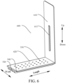
FIG. 6 is a schematic structural view of a second bottom support of a battery cell according to an embodiment of the present disclosure. -
FIG. 7 is a schematic structural view of a second bottom support of a battery cell according to an embodiment of the present disclosure viewed from another perspective. -
FIG. 8 is a schematic view of a battery pack according to an embodiment of the present disclosure. -
FIG 9 is a schematic view of a vehicle according to an embodiment of the present disclosure. -
FIG. 10 is a schematic view of a vehicle according to another embodiment of the present disclosure. - List of reference numerals:
- 1 battery cell,
- 100 housing, 110 inner cavity, 120 first side wall, 121 first limiting protrusion, 122 second limiting protrusion, 130 second side wall, 131 explosion-proof hole, 140 housing body, 150 housing cover,
- 200 terminal post, 210 positive electrode terminal post, 220 negative electrode terminal post, 300 explosion-proof valve, 400 electrode core,
- 500 first bottom support, 510 first gas channel, 520 second gas channel, 530 exhaust hole, 540 supporting rib, 550 first side plate, 551 first reinforcing rib, 560 first bottom plate,
- 600 second bottom support, 610 second side plate, 611 second reinforcing rib, 620 second bottom plate, 700 insulating film, 800 insulating spacer ring,
- 2 battery pack, 3 box, 4 vehicle.
- Embodiments of the present disclosure will be described in detail below, and examples thereof are illustrated in the drawings, where the same or similar elements or the elements having the same or similar functions are denoted by the same or similar reference numerals throughout the description. The embodiments described below with reference to the accompanying drawings are exemplary and merely intended to explain the present disclosure, and cannot be construed as a limitation on the present disclosure.
- In the descriptions of the present disclosure, it should be understood that the terms "center", "upper", "lower", "front", "rear", "left", "right", "vertical", "horizontal", "top" , "bottom", inner", "outer", and others indicate directional or position relations based on the directional or position relations shown in the drawings, and are merely provided for ease or brevity of description of the present disclosure, but do not necessarily mean or imply that the indicated device or component is provided in the specified direction or constructed or operated in the specified direction. Therefore, such terms should not be construed as limiting of the present disclosure.
- It is to be understood that the terms "first" and "second" are used merely for the purpose of description, and shall not be construed as indicating or implying relative importance or implying a quantity of indicated technical features. Therefore, a feature limited by "first" or "second" may explicitly or implicitly include one or more of the features. Further, in the descriptions of the present disclosure, unless otherwise indicated, "multiple" means two or more.
- A
battery cell 1 according to an embodiment of the present disclosure will be described below with reference to the accompanying drawings. - As shown in
FIGs. 1 to 7 , thebattery cell 1 according to the embodiment of the present disclosure includes ahousing 100, a firstbottom support 500, a secondbottom support 600, aterminal post 200, an explosion-proof valve 300 and anelectrode core 400. - The
housing 100 has aninner cavity 110, and afirst side wall 120 and asecond side wall 130 opposite to each other. Thesecond side wall 130 is provided with an explosion-proof hole 131. The firstbottom support 500 and the secondbottom support 600 are arranged in theinner cavity 110. Thesecond side wall 130 supports the firstbottom support 500 and the secondbottom support 600. The firstbottom support 500 is spaced apart from the secondbottom support 600, and the firstbottom support 500 and the secondbottom support 600 define afirst gas channel 510. The explosion-proof hole 131 is in communication with theinner cavity 110 through thefirst gas channel 510. Theterminal post 200 is arranged on a side wall of thehousing 100 other than thesecond side wall 130. The explosion-proof valve 300 is mounted on thesecond side wall 130, and the explosion-proof valve 300 is configured to cover the explosion-proof hole 131. Theelectrode core 400 is arranged in theinner cavity 110 and connected to theterminal post 200. The firstbottom support 500 and the secondbottom support 600 jointly support theelectrode core 400, such that theelectrode core 400 is spaced apart from the explosion-proof hole 131. - The explosion-
proof valve 300 has an explosion value. When the pressure in theinner cavity 110 of thebattery cell 1 is less than the explosion value of the explosion-proof valve 300, the battery is in a normal working state. When the pressure in theinner cavity 110 is greater than or equal to the explosion value of the explosion-proof valve 300, the explosion-proof valve 300 is opened and the gas is rapidly discharged, to rapidly reduce the pressure in theinner cavity 110, and prevent the explosion of thebattery cell 1. At this time, the explosion-proof valve 300 serves for explosion protection. - In the
battery cell 1 according to the embodiment of the present disclosure, thehousing 100 is provided with theinner cavity 110, and thefirst side wall 120 and thesecond side wall 130 opposite to each other, theterminal post 200 is arranged on a side wall of thehousing 100 other than thesecond side wall 130, thesecond side wall 130 is provided with the explosion-proof hole 131, the explosion-proof valve 300 is mounted on thesecond side wall 130 and configured to cover the explosion-proof hole 131, and theelectrode core 400 is arranged in theinner cavity 110 and connected to theterminal post 200. Since theterminal post 200 and the explosion-proof hole 131 are arranged on different walls of thehousing 100 respectively, theterminal post 200 is spaced apart from the explosion-proof hole 131. In the case of thermal runaway of thebattery cell 1, the high-temperature gas or flame ejected from the explosion-proof hole 131 will not burn theterminal post 200, to avoid the secondary harm and provide a high safety performance. Furthermore, theelectrode core 400 is arranged in thehousing 100 and spaced apart from the explosion-proof hole 131. Therefore, theelectrode core 400 will not block the explosion-proof hole 131, and the gas in thefirst gas channel 510 is in communication with the outside through the explosion-proof hole 131. - In addition, the first
bottom support 500 and the secondbottom support 600 are arranged in theinner cavity 110, and thesecond side wall 130 supports the firstbottom support 500 and the secondbottom support 600. Namely, the previous structure of thehousing 100 of thebattery cell 1 does not need to be changed in the embodiment of the present disclosure, and the firstbottom support 500 and the secondbottom support 600 are mounted in theinner cavity 110 of thehousing 100 as additional components. Therefore, the structure of thehousing 100 remains unchanged, so the processing difficulty of thehousing 100 is reduced. - Furthermore, the first
bottom support 500 and the secondbottom support 600 can support theelectrode core 400, such that theelectrode core 400 is spaced apart from thesecond side wall 130, and theelectrode core 400 is spaced apart from the explosion-proof hole 131. As a result, theelectrode core 400 will not block the explosion-proof hole 131 of thesecond side wall 130, and the gas flow through the explosion-proof hole 131 becomes much smooth when the explosion-proof valve 300 is opened. - Additionally, the first
bottom support 500 and the secondbottom support 600 are spaced apart and define thefirst gas channel 510, and the explosion-proof hole 131 is in communication with theinner cavity 110 through thefirst gas channel 510. - Since the explosion-
proof valve 300 is arranged on thesecond side wall 130 at a different side from theterminal post 200, the space between theelectrode core 400 and thesecond side wall 130 is small, and the gas generated by theelectrode core 400 cannot be stored. If the firstbottom support 500 and the secondbottom support 600 are not arranged to form thefirst gas channel 510, the gas generated by theelectrode core 400 will move to the space between theelectrode core 400 and thefirst side wall 120. Consequently, when the pressure in theinner cavity 110 reaches the explosion value of the explosion-proof valve 300, the gas in theinner cavity 110 cannot be quickly exhausted through the explosion-proof hole 131, causing a high hazard. - In the present disclosure, by arranging the first
bottom support 500 and the secondbottom support 600 to form thefirst gas channel 510 storing the gas generated by theelectrode core 400, when the pressure in theinner cavity 110 reaches the explosion value of the explosion-proof valve 300, the explosion-proof valve 300 is opened, and thefirst gas channel 510 is in communication with the outside through the explosion-proof hole 160. In this way, the gas in thebattery cell 1 can be quickly discharged from the explosion-proof hole 131, the gas flows smoothly, the gas is exhausted freely, and the explosion-proof effect is better. - Therefore, the
battery cell 1 according to the embodiment of the present disclosure has the advantages of high safety, smooth gas flow and good explosion-proof effect. - In some specific embodiments of the present disclosure, the
terminal post 200 is arranged on thefirst side wall 120, and the explosion-proof hole 131 is arranged on thesecond side wall 130. Namely, theterminal post 200 and the explosion-proof hole 131 are arranged at two opposite sides of thehousing 100. In this way, theterminal post 200 and the explosion-proof hole 131 are well spaced apart, and the distance between theterminal post 200 and the explosion-proof hole 131 is large. In the case of thermal runaway of thebattery cell 1, the high-temperature gas or flame ejected from the explosion-proof hole 131 will not burn theterminal post 200, to effectively avoid the secondary harm and provide a high safety performance. Furthermore, theelectrode core 400 will not block the explosion-proof hole 131, and the gas in thefirst gas channel 510 is in communication with the outside through the explosion-proof hole 131. - In some specific embodiments of the present disclosure, as shown in
FIGs. 2 to 7 , a side of at least one of the firstbottom support 500 and the secondbottom support 600 facing thesecond side wall 130 is configured with asecond gas channel 520, and thesecond gas channel 520 is in communication with thefirst gas channel 510. At least one of the firstbottom support 500 and the secondbottom support 600 is provided withmultiple exhaust holes 530, and thesecond gas channel 520 is in communication with theinner cavity 110 through the multiple exhaust holes 530. - The
second gas channel 520 can also be configured to store the gas generated by theelectrode core 400, to reduce the volume of thefirst gas channel 510. In this way, theinner cavity 110 can have more space to arrange theelectrode core 400, to ensure the energy density of thebattery cell 1. The firstbottom support 500 may be configured with thesecond gas channel 520 and theexhaust hole 530, and the secondbottom support 600 may be not configured with thesecond gas channel 520 and theexhaust hole 530. Alternatively, the firstbottom support 500 may be not configured with thesecond gas channel 520 and theexhaust hole 530, and the secondbottom support 600 may be configured with thesecond gas channel 520 and theexhaust hole 530. Alternatively the firstbottom support 500 and the secondbottom support 600 are both configured with thesecond gas channel 520 and theexhaust hole 530. - It can be understood that the
electrode core 400 of thebattery cell 1 generates gas. The gas generated by a portion of theelectrode core 400 corresponding to thefirst gas channel 510 in the length direction of thesecond side wall 130 can directly flow through thefirst gas channel 510 to the explosion-proof hole 131, the gas generated by a portion of theelectrode core 400 abutting against the firstbottom support 500 can flow through themultiple exhaust holes 530 on the firstbottom support 500 and thesecond gas channel 520 to thefirst gas channel 510 and the explosion-proof hole 131, and the gas generated by a portion of theelectrode core 400 abutting against the secondbottom support 600 can flow through themultiple exhaust holes 530 on the secondbottom support 600 and thesecond gas channel 520 to thefirst gas channel 510 and the explosion-proof hole 131. Therefore, various portions of theelectrode core 400 are maintained to be in communication with the explosion-proof hole 131, so the gas flows more smoothly, the exhaust effect of thebattery cell 1 is further improved, and the explosion-proof effect is better. - In some specific embodiments of the present disclosure, as shown in
FIGs. 6 and7 , the side of at least one of the firstbottom support 500 and the secondbottom support 600 facing thesecond side wall 130 is configured with multiple supportingribs 540, and thesecond gas channel 520 is defined between two adjacent supportingribs 540. - The multiple supporting
ribs 540 can increase the thickness of the firstbottom support 500 and the thickness of the secondbottom support 600, so that the structural strength of the firstbottom support 500 and the secondbottom support 600 is much higher, and the firstbottom support 500 and the secondbottom support 600 can support theelectrode core 400 more stably. Theelectrode core 400 can be stably spaced apart from the explosion-proof hole 131 by the firstbottom support 500 and the secondbottom support 600, the space of thefirst gas channel 510 is larger, and the ventilation effect is better. - Furthermore, by directly defining the
second gas channel 520 by adjacent supportingribs 540, the structure of thesecond gas channel 520 is simpler, which simplifies the structure of the firstbottom support 500 and the secondbottom support 600. A side of the supportingribs 540 facing away from theelectrode core 400 may abut against thesecond side wall 130, so that thesecond gas channel 520 will not be blocked, and the gas flows more smoothly. - In some specific embodiments of the present disclosure, as shown in
FIG. 2 , each supportingrib 540 has a height ranging from 0.5 mm to 3 mm. For example, the height of each supportingrib 540 may be 0.5 mm, 1 mm, 1.5 mm, 2 mm, 2.5 mm or 3 mm. - Therefore, on one hand, the supporting
rib 540 can have a larger height, so that thesecond gas channel 520 has more space, thesecond gas channel 520 is unlikely to be blocked and can hold more gas, the gas generated by theelectrode core 400 can be quickly exhausted for explosion protection, the gas flows more smoothly, and the explosion-proof effect is better. On the other hand, the height of the supportingrib 540 cannot be too large, so the space occupied by the firstbottom support 500 and the secondbottom support 600 in thebattery cell 1 will not be too large, to avoid large loss of the capacity of theelectrode core 400, and ensure the energy density of thebattery cell 1. - In some specific embodiments of the present disclosure, as shown in
FIGs. 2 and4 , thefirst gas channel 510 extends along a direction perpendicular to thesecond side wall 130, and thesecond gas channel 520 extends along the length direction of thesecond side wall 130. - It is to be understood that the explosion-
proof hole 131 may penetrate thesecond side wall 130 along the thickness direction of thesecond side wall 130. The extending direction of thefirst gas channel 510 is parallel to that of the explosion-proof hole 131. The extending length of thefirst gas channel 510 may be short, whereby the gas flow can quickly flow through thefirst gas channel 510 and be discharged to the outside of thebattery cell 1 through the explosion-proof hole 131. Furthermore, thesecond gas channel 520 occupies less space in theinner cavity 110 in a direction from thefirst side wall 120 to thesecond side wall 130. Therefore, while ensuring the fast flow of the gas, the space occupied by the firstbottom support 500 and the secondbottom support 600 is reduced, thus further avoiding the loss of the capacity of theelectrode core 400, and ensuring the energy density of thebattery cell 1. - In some specific embodiments of the present disclosure, as shown in
FIG. 2 , the dimension of theelectrode core 400 in the length direction of thesecond side wall 130 is L1, and the length of each of the firstbottom support 500 and the secondbottom support 600 is L2, where L1 and L2 meet: 0.04≤L2/L1≤0.45. For example, L2/L1 may be 0.04, 0.1, 0.15, 0.2, 0.25, 0.3, 0.35, 0.4 or 0.45. - In this way, on one hand, the dimension of the first
bottom support 500 and the secondbottom support 600 in the length direction of thesecond side wall 130 is avoided to be too small, and the firstbottom support 500 and the secondbottom support 600 can stably support theelectrode core 400, whereby theelectrode core 400 can be avoided to sink to directly contact with the explosion-proof hole 131, normal flow through the explosion-proof hole 131 is ensured, and the explosion-proof effect is good. On the other hand, the dimension of the firstbottom support 500 and the secondbottom support 600 in the length direction of thesecond side wall 130 is avoided to be too large, the dimension of thefirst gas channel 510 in the length direction of thesecond side wall 130 can be large, thefirst gas channel 510 has more space, the firstbottom support 500 and the secondbottom support 600 will not cover the explosion-proof hole 131, the gas is exhausted freely, the material for processing the firstbottom support 500 and the secondbottom support 600 is reduced, and the weight of the firstbottom support 500 and the secondbottom support 600 is reduced, thus saving the cost. - Further, the dimension L1 of the
electrode core 400 in the length direction of thesecond side wall 130 is ≤500 mm, and the length L2 of each of the firstbottom support 500 and the secondbottom support 600 is ≥ 20 mm. - Therefore, the length of the
electrode core 400 will not be too large, such that the whole length of thebattery cell 1 will not be too large, thus improving the overall structural strength of thebattery cell 1. In addition, the length of the firstbottom support 500 and the length of the secondbottom support 600 are not too short. Accordingly, the length of thefirst gas channel 510 is kept long enough, so that thefirst gas channel 510 has large space, thefirst gas channel 510 is uneasy to be blocked, and the gas is exhausted more smoothly. - In some specific embodiments of the present disclosure, as shown in
FIG. 3 , the explosion-proof valve 300 is arranged at a side of thesecond side wall 130 facing theinner cavity 110 or at a side of thesecond side wall 130 facing away from theinner cavity 110. The explosion-proof valve 300 can be welded to thesecond side wall 130. - For example, the explosion-
proof valve 300 is arranged at the side of thesecond side wall 130 facing theinner cavity 110. As a result, the explosion-proof valve 300 will not protrude from thehousing 100, and thehousing 100 can protect the explosion-proof valve 300. Alternatively, the explosion-proof valve 300 is arranged at the side of thesecond side wall 130 facing away from theinner cavity 110. Namely, the explosion-proof valve 300 is arranged outside thehousing 100. In this case, the assembly space outside thehousing 100 is larger, and the assembly of the explosion-proof valve 300 to thehousing 100 is more convenient. - In some specific embodiments of the present disclosure, the
battery cell 1 further includes a protective sheet (not shown). The protective sheet is connected to thehousing 100 and located at a side of the explosion-proof valve 300 facing away from theinner cavity 110. - The protective sheet can shield the explosion-
proof valve 300. Whether the explosion-proof valve 300 is mounted at the side of thesecond side wall 130 facing theinner cavity 110 or the explosion-proof valve 300 is arranged at the side of thesecond side wall 130 facing away from theinner cavity 110, the protective sheet can prevent other parts of thevehicle 4 from direct contact with the explosion-proof valve 300. Moreover, the protective sheet can also protect the explosion-proof valve 300 during the transportation of thebattery cell 1, to avoid the damage to the explosion-proof valve 300 due to bumps during transportation, and extend the service life of thebattery cell 1. - In some specific embodiments of the present disclosure, as shown in
FIGs. 6 and7 , the firstbottom support 500 includes afirst side plate 550 and afirst bottom plate 560 connected to each other, and the secondbottom support 600 includes asecond side plate 610 and asecond bottom plate 620 connected to each other. - The
first bottom plate 560 is connected to thesecond side wall 130, and thefirst bottom plate 560 extends along the length direction of thesecond side wall 130. One end of thefirst side plate 550 is connected to thefirst bottom plate 560, and the other end of thefirst side plate 550 is connected to one end of thefirst side wall 120. Thesecond bottom plate 620 is connected to thesecond side wall 130, and thesecond bottom plate 620 extends along the length direction of thesecond side wall 130. One end of thesecond side plate 610 is connected to thesecond bottom plate 620, and the other end of thesecond side plate 610 is connected to the other end of thefirst side wall 120. Thefirst bottom plate 560 and thesecond bottom plate 620 are spaced apart, and thefirst bottom plate 560 and thesecond bottom plate 620 define thefirst gas channel 510. - In this way, the contact area of the first
bottom support 500 and the secondbottom support 600 with the side walls of theinner cavity 110 is larger, the connected structure is more stable and reliable, so as to prevent the change of relative positions of the firstbottom support 500 and the secondbottom support 600 to thehousing 100. By arranging thefirst side plate 550 and thesecond side plate 610, two force transmission paths are added between thefirst side wall 120 and thesecond side wall 130, making the structural strength of thehousing 100 higher. - It is to be understood that the other end of the
first side plate 550 may be directly or indirectly connected to thefirst side wall 120. Namely, the other end of thefirst side plate 550 can be directly connected to one end of thefirst side wall 120; or thefirst side plate 550 can be connected, through an insulatingspacer ring 800, to one end of thefirst side wall 120. Similarly, the other end of thesecond side plate 610 may be directly or indirectly connected to thefirst side wall 120. Namely, the other end of thesecond side plate 610 can be directly connected to the other end of thefirst side wall 120; or thesecond side plate 610 can be connected, through the insulatingspacer ring 800, to the other end of thefirst side wall 120. - In some specific embodiments of the present disclosure, as shown in
FIGs. 4 to 6 , a side of thefirst side plate 550 facing theelectrode core 400 is arranged with a first reinforcingrib 551, and the first reinforcingrib 551 extends along a length direction of thefirst side plate 550. A side of thesecond side plate 610 facing theelectrode core 400 is arranged with a second reinforcingrib 611, and the second reinforcingrib 611 extends along a length direction of thesecond side plate 610. - By arranging the first reinforcing
rib 551, the structural strength of thefirst side plate 550 is improved, the overall structural strength of the firstbottom support 500 is higher, and the connection between thefirst side plate 550 and thefirst side wall 120 is more reliable. By arranging the second reinforcingrib 611, the structural strength of thesecond side plate 610 is improved, the overall structural strength of the secondbottom support 600 is higher, and the connection between thesecond side plate 610 and thefirst side wall 120 is more reliable. Accordingly, the firstbottom support 500 and the secondbottom support 600 can enhance the structural strength of thehousing 100. - In some specific embodiments of the present disclosure, as shown in
FIGs. 2 and4 , thefirst side plate 550 is parallel to thesecond side plate 610 and perpendicular to thesecond side wall 130. - It can be understood that side walls of the
housing 100 connected to two ends of thesecond side wall 130 in the length direction are perpendicular to thesecond side wall 130. Namely, both thefirst side plate 550 and thesecond side plate 610 are parallel to the side walls connected to two ends of thesecond side wall 130 in the length direction. Thus, thefirst side plate 550 and thesecond side plate 610 can be attached to the side walls of theinner cavity 110. As a result, thefirst side plate 550 and thesecond side plate 610 occupy less space in theinner cavity 110, and thefirst side plate 550 and thesecond side plate 610 cause less loss of the capacity of theelectrode core 400, thereby ensuring the energy density of thebattery cell 1. - In some specific embodiments of the present disclosure, a side of the insulating
spacer ring 800 facing theinner cavity 110 may be defined with a first limitingprotrusion 121 and a second limitingprotrusion 122. Thefirst side plate 550 abuts against a side of the first limitingprotrusion 121 facing away from the second limitingprotrusion 122, and thesecond side plate 610 abuts against a side of the second limitingprotrusion 122 facing away from the first limitingprotrusion 121. - For example, one end of the
first side plate 550 facing away from thesecond side wall 130 may be connected to the first limitingprotrusion 121 by, without limitation, hot melt connection, snap-fit connection or pin-hole connection. One end of thesecond side plate 610 facing away from thesecond side wall 130 may be connected to the second limitingprotrusion 122 by, without limitation, hot melt connection, snap-fit connection or pin-hole connection. - In this manner, the first limiting
protrusion 121 and the second limitingprotrusion 122 can limit the firstbottom support 500 and the secondbottom support 600 in the length direction of thefirst side wall 120, to avoid the change of the relative position of thefirst side wall 120, the firstbottom support 500 and the secondbottom support 600, and allow the firstbottom support 500 and the secondbottom support 600 to support theelectrode core 400 more stably. - In some specific embodiments of the present disclosure, as shown in
FIG. 1 , the explosion-proof hole 131 is located at a center of theelectrode core 400 in a thickness direction; and/or, the explosion-proof hole 131 is located at a center of theelectrode core 400 in the length direction of thesecond side wall 130. - For example, the explosion-
proof hole 131 can be located at the center of theelectrode core 400 in the thickness direction, and at the center of theelectrode core 400 in the length direction of thesecond side wall 130. Generally, the gas is mostly generated at the center of theelectrode core 400. By arranging the explosion-proof hole 131 at the center of theelectrode core 400, the explosion-proof valve 300 can more effectively sense the gas pressure in thebattery cell 1. When the gas pressure in thebattery cell 1 is too high, the explosion-proof valve 300 can be immediately opened to exhaust the gas in thebattery cell 1, thereby further improving the explosion-proof effect of thebattery cell 1. - In addition, such an arrangement makes the structure of the
housing 100 symmetrical in the length direction of thesecond side wall 130 and thehousing 100 have the same structural strength at two ends of thesecond side wall 130 in the length direction. This is beneficial to maintaining the consistency in structural strength of thehousing 100. - In some specific embodiments of the present disclosure, the
battery cell 1 further includes an insulatingfilm 700, where the insulatingfilm 700 is arranged at a side of the explosion-proof valve 300 facing theinner cavity 110. For example, the insulatingfilm 700 may be polypropylene (PP), polyethylene (PE) or other polyester compounds. - Particularly, the insulating
film 700 is arranged in theinner cavity 110 and between the explosion-proof valve 300 and theelectrode core 400. By arranging the insulatingfilm 700, the explosion-proof valve 300 can be isolated from the electrolyte solution, to prevent the corrosion of the explosion-proof valve 300 due to long time of soaking in the electrolyte solution, prevent the battery from leakage, avoid the increase or decrease of the opening pressure of the explosion-proof valve 300 due to the influence of the electrolyte solution, and enable the explosion-proof valve 300 to be in a stable and reliable working state. - In some specific embodiments of the present disclosure, as shown in
FIGs. 4 and 5 , theterminal post 200 includes a positiveelectrode terminal post 210 and a negativeelectrode terminal post 220. Thehousing 100 is an aluminum housing. In this case, the explosion-proof valve 300 is made of aluminum, the positiveelectrode terminal post 210 is electrically connected to thehousing 100, and a difference between the voltage of the positiveelectrode terminal post 210 and the voltage of thehousing 100 ranges from 0 V to 2.5V. The difference between the voltage of the positiveelectrode terminal post 210 and the voltage of thehousing 100 refers to a value obtained by the voltage of the positiveelectrode terminal post 210 minus the voltage of thehousing 100. - It is to be understood that the
housing 100 and the explosion-proof valve 300 can be made of metal aluminum or an aluminum alloy, and the electrolyte solution in thebattery cell 1 is usually a lithium ion electrolyte solution. Aluminum will react with lithium ions at a low potential to form a metal compound. Therefore, if the voltage difference between the positiveelectrode terminal post 210 and thehousing 100 is small, the voltage of thehousing 100 will approximate the voltage of the positiveelectrode terminal post 210, that is, the potential of thehousing 100 is increased. By means of this, thehousing 100 and the explosion-proof valve 300 are prevented from being corroded by the lithium ion electrolyte solution, and thehousing 100 and the explosion-proof valve 300 mounted on thehousing 100 are protected, thus further preventing thehousing 100 and the explosion-proof valve 300 from being corroded, and prolonging the service life of thebattery cell 1. - Further, a resistor is connected between the positive
electrode terminal post 210 and thehousing 100. Therefore, even if the positiveelectrode terminal post 210 and thehousing 100 of thebattery cell 1 form a loop, for example, when the positiveelectrode terminal post 210 of thebattery cell 1 is connected to a negative electrode of a battery without a resistor and thehousing 100 is connected to a positive electrode of the battery, the resistor between the positiveelectrode terminal post 210 and thehousing 100 of thebattery cell 1 can protect thebattery cell 1, to avoid the short circuit of thebattery cell 1, and enable thebattery cell 1 to have a high safety performance during use. - In some specific embodiments of the present disclosure, as shown in
FIGs. 4 and 5 , theterminal post 200 includes a positiveelectrode terminal post 210 and a negativeelectrode terminal post 220. Thehousing 100 is a steel housing. In this case, the explosion-proof valve 300 may be made of steel. The negativeelectrode terminal post 220 is electrically connected to thehousing 100, and a difference between the voltage of thehousing 100 and the voltage of the negativeelectrode terminal post 220 ranges from 0V to 2.5V. The difference between the voltage of thehousing 100 and the voltage of the negativeelectrode terminal post 220 refers to a value obtained by the voltage of thehousing 100 minus the voltage of the negativeelectrode terminal post 220. - It is to be understood that steel will react with lithium ions at a high potential to form a metal compound. If the voltage difference between the negative
electrode terminal post 220 and thehousing 100 is small, the voltage of thehousing 100 will approximate the voltage of the negativeelectrode terminal post 220, that is, the potential of thehousing 100 is reduced. By means of this, thehousing 100 and the explosion-proof valve 300 are prevented from being corroded by the lithium ion electrolyte solution, and thehousing 100 and the explosion-proof valve 300 mounted on thehousing 100 are protected, thus further preventing thehousing 100 and the explosion-proof valve 300 from being corroded, and prolonging the service life of thebattery cell 1. - Further, a resistor is connected between the negative
electrode terminal post 220 and thehousing 100. Therefore, even if the negativeelectrode terminal post 220 and thehousing 100 of thebattery cell 1 form a loop, for example, when the negativeelectrode terminal post 220 of thebattery cell 1 is connected to a positive electrode of a battery without a resistor and thehousing 100 is connected to a negative electrode of the battery, the resistor between the negativeelectrode terminal post 220 and thehousing 100 of thebattery cell 1 can protect thebattery cell 1, to avoid the short circuit of thebattery cell 1, and enable thebattery cell 1 to have a high safety performance during use. - In some specific embodiments of the present disclosure, as shown in
FIGs. 1, 2 and5 , thehousing 100 includes ahousing body 140 and ahousing cover 150. Thehousing 100 may be made of an aluminum alloy. - The
second side wall 130 and theinner cavity 110 are formed on thehousing body 140, thehousing body 140 is provided with an opening facingsecond side wall 130, and the opening is in communication with theinner cavity 110. Thehousing cover 150 is mounted to thehousing body 140 and covers theinner cavity 110, thefirst side wall 120 is formed on thehousing cover 150, and theterminal post 200 is connected to thehousing cover 150. By configuring thehousing 100 to include separate components, the processing difficulty of thehousing 100 is reduced, to simplify the processing steps of thehousing body 140 and thehousing cover 150, and make the processing more convenient; and also, it is convenient to put theelectrode core 400 and the electrolyte solution into theinner cavity 110. - As shown in
FIG. 8 , abattery pack 2 according to an embodiment in the second aspect of the present disclosure includes abox 3 and thebattery cell 1 according to the embodiment in the first aspect of the present disclosure. Thebattery cell 1 is mounted in thebox 3, with the explosion-proof valve 300 facing a bottom wall of thebox 3. Therefore, in the case of thermal runaway of the battery cell, high-temperature gas or flame can be ejected through the explosion-proof valve 300 to the bottom of thebox 3. - The
battery pack 2 according to the embodiment of the present disclosure, has the advantages of high safety, smooth gas flow and good explosion-proof effect, by using thebattery cell 1 according to the embodiment the present disclosure. - As shown in
FIGs. 9 and 10 , avehicle 4 according to an embodiment in the third aspect of the present disclosure includes thebattery cell 1 according to the embodiment in the first aspect of the present disclosure or thebattery pack 2 according to the embodiment in the second aspect of the present disclosure. Thebattery pack 2 is mounted to a vehicle body of thevehicle 4 or a chassis of thevehicle 4 by means of thebox 3. Alternatively, thevehicle 4 includes thebattery cell 1 according to the embodiment of the present disclosure, where thebattery cell 1 is mounted to the vehicle body of thevehicle 4 or the chassis of thevehicle 4. That is, thebattery cell 1 can be directly mounted to the vehicle body of thevehicle 4 or the chassis of thevehicle 4. Alternatively, thebattery cell 1 is mounted in thebox 3 and assembled into thebattery pack 2, and thebattery pack 2 is mounted to the vehicle body of thevehicle 4 or the chassis of thevehicle 4 by means of thebox 3. - The
vehicle 4 according to the embodiment of the present disclosure has the advantages of high safety, smooth gas flow and good explosion-proof effect, by using thebattery cell 1 according to the embodiment the present disclosure and thebattery pack 2 according to the embodiment the present disclosure. - In some specific embodiments of the present disclosure, the
battery cell 1 or thebattery pack 2 is mounted to the vehicle body of thevehicle 4 or the chassis of thevehicle 4, with thefirst side wall 120 located above thesecond side wall 130. - Particularly, the
first side wall 120 may face the interior of thevehicle 4, and thesecond side wall 130 may face the exterior of thevehicle 4. Namely, the explosion-proof valve 300 may face away from the passenger compartment of thevehicle 4. When thebattery cell 1 experiences thermal runaway, high-temperature gas or flame can be ejected through the explosion-proof valve 300 in a direction away from the passenger compartment of thevehicle 4, thereby preventing the flame from being directly ejected into the car, reducing the probability of injury of passengers in the vehicle, and further protecting the safety of the passengers in the vehicle. - Other configurations and operations of the
battery cell 1, thebattery pack 2, and thevehicle 4 according to the embodiments of the present disclosure are known to those of ordinary skill in the art and will not be described in detail herein. - In the description of the specification, the description with reference to the terms "an embodiment", "some embodiments", "exemplary embodiments", "example", "specific example", or "some examples" and so on means that specific features, structures, materials or characteristics described in connection with the embodiment or example are embraced in at least one embodiment or example of the present disclosure. In the specification, exemplary descriptions of the foregoing terms do not necessarily refer to the same embodiment or example. In addition, the described specific features, structures, materials or characteristics may be combined in any suitable manner in one or more embodiments.
- Although the embodiments of the present disclosure have been shown and described, a person of ordinary skill in the art should understand that various changes, modifications, replacements and variations may be made to the embodiments without departing from the principles and spirit of the present disclosure, and the scope of the present disclosure is as defined by the appended claims and their equivalents.
Claims (19)
- A battery cell (1), comprising:a housing (100), the housing (100) having an inner cavity (110) and a first side wall (120) and a second side wall (130) opposite to each other, and the second side wall (130) being provided with an explosion-proof hole (131);a first bottom support (500) and a second bottom support (600), the first bottom support (500) and the second bottom support (600) being arranged in the inner cavity (110), the second side wall (130) supporting the first bottom support (500) and the second bottom support (600), the first bottom support (500) being spaced apart from the second bottom support (600), the first bottom support (500) and the second bottom support (600) defining the first gas channel (510), and the explosion-proof hole (131) being in communication with the inner cavity (110) through the first gas channel (510);a terminal post (200), the terminal post (200) being arranged on a side wall of the housing (100) other than the second side wall (130);an explosion-proof valve (300), the explosion-proof valve (300) being mounted on the second side wall (130), and the explosion-proof valve (300) being configured to cover the explosion-proof hole (131); andan electrode core (400), the electrode core (400) being arranged in the inner cavity (110) and connected to the terminal post (200), and the first bottom support (500) and the second bottom support (600) jointly supporting the electrode core (400), and the electrode core (400) is spaced apart from the explosion-proof hole (131).
- The battery cell (1) according to claim 1, wherein a side of at least one of the first bottom support (500) and the second bottom support (600) facing the second side wall (130) is configured with a second gas channel (520), the second gas channel (520) is in communication with the first gas channel, at least one of the first bottom support (500) and the second bottom support (600) is provided with a plurality of exhaust holes (530), and the second gas channel (520) is in communication with the inner cavity (110) through the plurality of exhaust holes (530).
- The battery cell (1) according to claim 2, wherein the side of at least one of the first bottom support (500) and the second bottom support (600) facing the second side wall (130) is configured with a plurality of supporting ribs (540), the second gas channel (520) is defined between two adjacent supporting ribs (540).
- The battery cell (1) according to claim 3, wherein each supporting rib (540) has a height ranging from 0.5 mm to 3 mm.
- The battery cell (1) according to any one of claims 2 to 4, wherein the first gas channel (510) extends along a direction perpendicular to the second side wall (130), and the second gas channel (520) extends along a length direction of the second side wall (130).
- The battery cell (1) according to any one of claims 1 to 5, wherein the dimension of the electrode core (400) in the length direction of the second side wall (130) is L1, and a length of each of the first bottom support (500) and the second bottom support (600) is L2, wherein L1 and L2 meet: 0.04≤L2/L1≤0.45.
- The battery cell (1) according to claim 6, wherein L1 and L2 further meet: L1≤500mm, and L2≥20mm.
- The battery cell (1) according to any one of claims 1 to 7, wherein the first bottom support (500) comprises a first side plate (550) and a first bottom plate (560) connected to each other, the first bottom plate (560) is connected to the second side wall (130), the first bottom plate (560) extends along the length direction of the second side wall (130), one end of the first side plate (550) is connected to the first bottom plate (560), and the other end of the first side plate (550) is connected to one end of the first side wall (120); andthe second bottom support (600) comprises a second side plate (610) and a second bottom plate (620) connected to each other, the second bottom plate (620) is connected to the second side wall (130), the second bottom plate (620) extends along the length direction of the second side wall (130), one end of the second side plate (610) is connected to the second bottom plate (620), and the other end of the second side plate (610) is connected to the other end of the first side wall (120),wherein the first bottom plate (560) is spaced apart from the second bottom plate (620), and the first bottom plate (560) and the second bottom plate (620) define the first gas channel (51).
- The battery cell (1) according to claim 8, wherein a side of the first side plate (550) facing the electrode core (400) is arranged with a first reinforcing rib (551), and the first reinforcing rib (551) extends along a length direction of the first side plate (550); and
a side of the second side plate (610) facing the electrode core (400) is arranged with a second reinforcing rib (611), and the second reinforcing rib (611) extends along a length direction of the second side plate (610). - The battery cell (1) according to claim 8 or 9, wherein the first side plate (550) is parallel to the second side plate (610) and perpendicular to the second side wall (130).
- The battery cell (1) according to any one of claims 8 to 10, wherein the first side plate (550) is connected, through an insulating spacer ring (800), to the one end of the first side wall (120), and the second side plate (610) is connected, through the insulating spacer ring (800), to the other end of the first side wall (120); and
a side of the insulating spacer ring (800) facing the inner cavity (110) is arranged with a first limiting protrusion (121) and a second limiting protrusion (122), the first side plate (550) abuts against a side of the first limiting protrusion (121) facing away from the second limiting protrusion (122), and the second side plate (610) abuts against a side of the second limiting protrusion (122) facing away from the first limiting protrusion (121). - The battery cell (1) according to any one of claims 1 to 11, wherein the explosion-proof hole (131) is located at a center of the electrode core (400) in a thickness direction; and/or
the explosion-proof hole (131) is located at a center of the electrode core (400) in the length direction of the second side wall (130). - The battery cell (1) according to any one of claims 1 to 12, further comprising:
an insulating film (700), the insulating film (700) being arranged at a side of the explosion-proof valve (300) facing the inner cavity (110). - The battery cell (1) according to any one of claims 1 to 13, wherein the terminal post (200) is arranged on the first side wall (120).
- The battery cell (1) according to any one of claims 1 to 14, wherein the terminal post (200) comprises a positive electrode terminal post (210) and a negative electrode terminal post (220), the housing (100) is an aluminum housing, the positive electrode terminal post (210) is electrically connected to the housing (100), and a difference between the voltage of the positive electrode terminal post (210) and the voltage of the housing (100) is not less than 0 V and not greater than 2.5 V
- The battery cell (1) according to any one of claims 1 to 14, wherein the terminal post (200) comprises a positive electrode terminal post (210) and a negative electrode terminal post (220), the housing (100) is a steel housing, the negative electrode terminal post (220) is electrically connected to the housing (100), and a difference between the voltage of the housing (100) and the voltage of the negative electrode terminal post (220) is not less than 0 V and not greater than 2.5 V
- The battery cell (1) according to any one of claims 1 to 16, wherein the housing (100) comprises:a housing body (140), wherein the second side wall (130) and the inner cavity (110) are formed on the housing body (140), the housing body (140) is provided with an opening facing the second side wall (130), and the opening is in communication with the inner cavity (110); anda housing cover (150), wherein the housing cover (150) is mounted to the housing body (140) and covers the inner cavity (110), the first side wall (120) is formed on the housing cover (150), and the terminal post (200) is connected to the housing cover (150).
- A battery pack (2), comprising:a box (3); anda battery cell according to any one of claims 1 to 17, the battery cell (1) being mounted in the box (3), with the explosion-proof valve (300) facing a bottom wall of the box (3).
- Avehicle (4), comprising: a battery cell (1) according to any one of claims 1 to 17 or a battery pack (2) according to claim 18, with the first side wall (120) being located above the second side wall (130).
Applications Claiming Priority (2)
| Application Number | Priority Date | Filing Date | Title |
|---|---|---|---|
| CN202221130465.5U CN217788703U (en) | 2022-05-12 | 2022-05-12 | Single battery, battery pack and vehicle |
| PCT/CN2023/093419 WO2023217212A1 (en) | 2022-05-12 | 2023-05-11 | Battery cell, battery pack and vehicle |
Publications (2)
| Publication Number | Publication Date |
|---|---|
| EP4525168A1 true EP4525168A1 (en) | 2025-03-19 |
| EP4525168A4 EP4525168A4 (en) | 2026-04-22 |
Family
ID=83909638
Family Applications (1)
| Application Number | Title | Priority Date | Filing Date |
|---|---|---|---|
| EP23802981.3A Pending EP4525168A4 (en) | 2022-05-12 | 2023-05-11 | BATTERY CELL, BATTERY PACK AND VEHICLE |
Country Status (6)
| Country | Link |
|---|---|
| US (1) | US20250070411A1 (en) |
| EP (1) | EP4525168A4 (en) |
| JP (1) | JP2025515219A (en) |
| KR (1) | KR20250005218A (en) |
| CN (1) | CN217788703U (en) |
| WO (1) | WO2023217212A1 (en) |
Families Citing this family (9)
| Publication number | Priority date | Publication date | Assignee | Title |
|---|---|---|---|---|
| CN217788703U (en) * | 2022-05-12 | 2022-11-11 | 比亚迪股份有限公司 | Single battery, battery pack and vehicle |
| CN219067123U (en) * | 2022-12-21 | 2023-05-23 | 蜂巢能源科技股份有限公司 | battery cell |
| CN115842212A (en) * | 2022-12-29 | 2023-03-24 | 蜂巢能源科技股份有限公司 | Battery and power equipment |
| CN118679640A (en) * | 2023-01-19 | 2024-09-20 | 宁德时代新能源科技股份有限公司 | Battery monomer, battery and power consumption device |
| CN219498080U (en) * | 2023-02-20 | 2023-08-08 | 蜂巢能源科技股份有限公司 | Plastic plate, cover plate assembly and battery |
| CN119864585A (en) * | 2023-10-20 | 2025-04-22 | 宁德时代新能源科技股份有限公司 | Battery monomer and battery and electric equipment with same |
| CN117613401A (en) * | 2023-11-30 | 2024-02-27 | 蜂巢能源科技股份有限公司 | Single battery and battery pack |
| CN117766939B (en) * | 2023-12-22 | 2024-09-17 | 蜂巢能源科技股份有限公司 | Battery and battery pack |
| CN222927620U (en) * | 2024-07-01 | 2025-05-30 | 惠州亿纬锂能股份有限公司 | Battery monomer and battery pack |
Family Cites Families (11)
| Publication number | Priority date | Publication date | Assignee | Title |
|---|---|---|---|---|
| JP2001257004A (en) * | 2000-03-13 | 2001-09-21 | Japan Storage Battery Co Ltd | Battery |
| JP2009021133A (en) * | 2007-07-12 | 2009-01-29 | Toshiba Corp | Nonaqueous electrolyte secondary battery |
| JP5446081B2 (en) * | 2007-10-05 | 2014-03-19 | 株式会社Gsユアサ | battery |
| JP5227752B2 (en) * | 2007-11-26 | 2013-07-03 | 日立マクセル株式会社 | Sealed battery, battery pack using the sealed battery, and electronic device equipped with the battery pack |
| JP2012009317A (en) * | 2010-06-25 | 2012-01-12 | Hitachi Vehicle Energy Ltd | Lithium-ion secondary battery and battery pack |
| US9472802B2 (en) * | 2011-07-25 | 2016-10-18 | Samsung Sdi Co., Ltd. | Secondary battery |
| JP6064389B2 (en) * | 2012-06-28 | 2017-01-25 | 株式会社Gsユアサ | Storage element assembly |
| CN107394063B (en) * | 2016-05-16 | 2023-06-06 | 宁德时代新能源科技股份有限公司 | Secondary battery |
| KR102245620B1 (en) * | 2016-08-18 | 2021-04-27 | 삼성에스디아이 주식회사 | Rechargeable battery |
| CN207938693U (en) * | 2018-03-07 | 2018-10-02 | 深圳市领域通科技有限公司 | A kind of Novel compressive lithium battery |
| CN217788703U (en) * | 2022-05-12 | 2022-11-11 | 比亚迪股份有限公司 | Single battery, battery pack and vehicle |
-
2022
- 2022-05-12 CN CN202221130465.5U patent/CN217788703U/en active Active
-
2023
- 2023-05-11 JP JP2024566713A patent/JP2025515219A/en active Pending
- 2023-05-11 EP EP23802981.3A patent/EP4525168A4/en active Pending
- 2023-05-11 WO PCT/CN2023/093419 patent/WO2023217212A1/en not_active Ceased
- 2023-05-11 KR KR1020247036788A patent/KR20250005218A/en active Pending
-
2024
- 2024-11-08 US US18/941,380 patent/US20250070411A1/en active Pending
Also Published As
| Publication number | Publication date |
|---|---|
| WO2023217212A1 (en) | 2023-11-16 |
| US20250070411A1 (en) | 2025-02-27 |
| JP2025515219A (en) | 2025-05-13 |
| CN217788703U (en) | 2022-11-11 |
| KR20250005218A (en) | 2025-01-09 |
| EP4525168A4 (en) | 2026-04-22 |
Similar Documents
| Publication | Publication Date | Title |
|---|---|---|
| US20250070411A1 (en) | Battery cell, battery pack and vehicle | |
| EP4525174A1 (en) | Battery cell, battery pack and vehicle | |
| EP4525165A1 (en) | Battery cell, battery pack and vehicle | |
| KR102952415B1 (en) | Battery pack with improved fixing structure and gas exhausting structure, and Electronic device and Vehicle comprising the Same | |
| EP3965213B1 (en) | Battery and related apparatus thereof, preparation method and preparation device | |
| US11949119B2 (en) | Cover assembly of secondary battery and secondary battery | |
| KR20240154609A (en) | Explosion-proof valves, batteries, battery modules, battery packs and vehicles | |
| US11916249B2 (en) | Cover assembly of secondary battery and secondary battery | |
| KR102918645B1 (en) | Battery pack and Vehicle comprising the same | |
| JP7553574B2 (en) | Battery packs and automobiles containing the same | |
| KR102798704B1 (en) | Battery module, battery pack and vehicle including the same | |
| US20240347822A1 (en) | End cover assembly, battery cell, battery, and electrical apparatus | |
| WO2023130924A1 (en) | Gas discharge device, battery cell, battery, and electric device | |
| JP2024512999A (en) | Battery module with improved safety | |
| CN223321409U (en) | Battery housing and single battery | |
| JP7447279B2 (en) | Battery packs, electronic devices containing them, and automobiles | |
| JP2024519793A (en) | VENTING DEVICE AND PLANETARY SECONDARY BATTERY EQUIPPED WITH SAME | |
| CN223123995U (en) | Battery cell and battery pack | |
| JP7773632B2 (en) | Battery housing, battery, electrical device, method and apparatus for manufacturing battery | |
| CN222883810U (en) | Battery cells, batteries and electrical devices | |
| US20260135206A1 (en) | Battery cell, battery, and electric device | |
| CN223038980U (en) | Gemini cells, battery packs and vehicles | |
| CN122026032A (en) | battery cell | |
| CN121153160A (en) | Battery cells, batteries and electrical devices | |
| CN121529105A (en) | A battery cell, a top bracket, and an electrical device. |
Legal Events
| Date | Code | Title | Description |
|---|---|---|---|
| STAA | Information on the status of an ep patent application or granted ep patent |
Free format text: STATUS: THE INTERNATIONAL PUBLICATION HAS BEEN MADE |
|
| PUAI | Public reference made under article 153(3) epc to a published international application that has entered the european phase |
Free format text: ORIGINAL CODE: 0009012 |
|
| STAA | Information on the status of an ep patent application or granted ep patent |
Free format text: STATUS: REQUEST FOR EXAMINATION WAS MADE |
|
| 17P | Request for examination filed |
Effective date: 20241031 |
|
| AK | Designated contracting states |
Kind code of ref document: A1 Designated state(s): AL AT BE BG CH CY CZ DE DK EE ES FI FR GB GR HR HU IE IS IT LI LT LU LV MC ME MK MT NL NO PL PT RO RS SE SI SK SM TR |
|
| DAV | Request for validation of the european patent (deleted) | ||
| DAX | Request for extension of the european patent (deleted) | ||
| A4 | Supplementary search report drawn up and despatched |
Effective date: 20260325 |
|
| RIC1 | Information provided on ipc code assigned before grant |
Ipc: H01M 50/342 20210101AFI20260319BHEP Ipc: H01M 50/367 20210101ALI20260319BHEP Ipc: H01M 50/249 20210101ALI20260319BHEP Ipc: H01M 50/588 20210101ALI20260319BHEP Ipc: H01M 50/593 20210101ALI20260319BHEP Ipc: H01M 50/103 20210101ALI20260319BHEP Ipc: B60R 16/04 20060101ALI20260319BHEP Ipc: H01M 50/15 20210101ALI20260319BHEP |