EP4525157A1 - Housing, housing assembly, battery, and electrical device - Google Patents
Housing, housing assembly, battery, and electrical device Download PDFInfo
- Publication number
- EP4525157A1 EP4525157A1 EP22969835.2A EP22969835A EP4525157A1 EP 4525157 A1 EP4525157 A1 EP 4525157A1 EP 22969835 A EP22969835 A EP 22969835A EP 4525157 A1 EP4525157 A1 EP 4525157A1
- Authority
- EP
- European Patent Office
- Prior art keywords
- end wall
- box
- mounting member
- hoisting
- box body
- Prior art date
- Legal status (The legal status is an assumption and is not a legal conclusion. Google has not performed a legal analysis and makes no representation as to the accuracy of the status listed.)
- Pending
Links
Images






Classifications
-
- H—ELECTRICITY
- H01—ELECTRIC ELEMENTS
- H01M—PROCESSES OR MEANS, e.g. BATTERIES, FOR THE DIRECT CONVERSION OF CHEMICAL ENERGY INTO ELECTRICAL ENERGY
- H01M50/00—Constructional details or processes of manufacture of the non-active parts of electrochemical cells other than fuel cells, e.g. hybrid cells
- H01M50/20—Mountings; Secondary casings or frames; Racks, modules or packs; Suspension devices; Shock absorbers; Transport or carrying devices; Holders
- H01M50/249—Mountings; Secondary casings or frames; Racks, modules or packs; Suspension devices; Shock absorbers; Transport or carrying devices; Holders specially adapted for aircraft or vehicles, e.g. cars or trains
-
- B—PERFORMING OPERATIONS; TRANSPORTING
- B60—VEHICLES IN GENERAL
- B60K—ARRANGEMENT OR MOUNTING OF PROPULSION UNITS OR OF TRANSMISSIONS IN VEHICLES; ARRANGEMENT OR MOUNTING OF PLURAL DIVERSE PRIME-MOVERS IN VEHICLES; AUXILIARY DRIVES FOR VEHICLES; INSTRUMENTATION OR DASHBOARDS FOR VEHICLES; ARRANGEMENTS IN CONNECTION WITH COOLING, AIR INTAKE, GAS EXHAUST OR FUEL SUPPLY OF PROPULSION UNITS IN VEHICLES
- B60K1/00—Arrangement or mounting of electrical propulsion units
- B60K1/04—Arrangement or mounting of electrical propulsion units of the electric storage means for propulsion
-
- H—ELECTRICITY
- H01—ELECTRIC ELEMENTS
- H01M—PROCESSES OR MEANS, e.g. BATTERIES, FOR THE DIRECT CONVERSION OF CHEMICAL ENERGY INTO ELECTRICAL ENERGY
- H01M10/00—Secondary cells; Manufacture thereof
- H01M10/60—Heating or cooling; Temperature control
- H01M10/61—Types of temperature control
- H01M10/613—Cooling or keeping cold
-
- H—ELECTRICITY
- H01—ELECTRIC ELEMENTS
- H01M—PROCESSES OR MEANS, e.g. BATTERIES, FOR THE DIRECT CONVERSION OF CHEMICAL ENERGY INTO ELECTRICAL ENERGY
- H01M10/00—Secondary cells; Manufacture thereof
- H01M10/60—Heating or cooling; Temperature control
- H01M10/62—Heating or cooling; Temperature control specially adapted for specific applications
- H01M10/625—Vehicles
-
- H—ELECTRICITY
- H01—ELECTRIC ELEMENTS
- H01M—PROCESSES OR MEANS, e.g. BATTERIES, FOR THE DIRECT CONVERSION OF CHEMICAL ENERGY INTO ELECTRICAL ENERGY
- H01M10/00—Secondary cells; Manufacture thereof
- H01M10/60—Heating or cooling; Temperature control
- H01M10/65—Means for temperature control structurally associated with the cells
- H01M10/656—Means for temperature control structurally associated with the cells characterised by the type of heat-exchange fluid
- H01M10/6567—Liquids
-
- H—ELECTRICITY
- H01—ELECTRIC ELEMENTS
- H01M—PROCESSES OR MEANS, e.g. BATTERIES, FOR THE DIRECT CONVERSION OF CHEMICAL ENERGY INTO ELECTRICAL ENERGY
- H01M50/00—Constructional details or processes of manufacture of the non-active parts of electrochemical cells other than fuel cells, e.g. hybrid cells
- H01M50/20—Mountings; Secondary casings or frames; Racks, modules or packs; Suspension devices; Shock absorbers; Transport or carrying devices; Holders
- H01M50/204—Racks, modules or packs for multiple batteries or multiple cells
-
- H—ELECTRICITY
- H01—ELECTRIC ELEMENTS
- H01M—PROCESSES OR MEANS, e.g. BATTERIES, FOR THE DIRECT CONVERSION OF CHEMICAL ENERGY INTO ELECTRICAL ENERGY
- H01M50/00—Constructional details or processes of manufacture of the non-active parts of electrochemical cells other than fuel cells, e.g. hybrid cells
- H01M50/20—Mountings; Secondary casings or frames; Racks, modules or packs; Suspension devices; Shock absorbers; Transport or carrying devices; Holders
- H01M50/233—Mountings; Secondary casings or frames; Racks, modules or packs; Suspension devices; Shock absorbers; Transport or carrying devices; Holders characterised by physical properties of casings or racks, e.g. dimensions
-
- H—ELECTRICITY
- H01—ELECTRIC ELEMENTS
- H01M—PROCESSES OR MEANS, e.g. BATTERIES, FOR THE DIRECT CONVERSION OF CHEMICAL ENERGY INTO ELECTRICAL ENERGY
- H01M50/00—Constructional details or processes of manufacture of the non-active parts of electrochemical cells other than fuel cells, e.g. hybrid cells
- H01M50/20—Mountings; Secondary casings or frames; Racks, modules or packs; Suspension devices; Shock absorbers; Transport or carrying devices; Holders
- H01M50/233—Mountings; Secondary casings or frames; Racks, modules or packs; Suspension devices; Shock absorbers; Transport or carrying devices; Holders characterised by physical properties of casings or racks, e.g. dimensions
- H01M50/242—Mountings; Secondary casings or frames; Racks, modules or packs; Suspension devices; Shock absorbers; Transport or carrying devices; Holders characterised by physical properties of casings or racks, e.g. dimensions adapted for protecting batteries against vibrations, collision impact or swelling
-
- H—ELECTRICITY
- H01—ELECTRIC ELEMENTS
- H01M—PROCESSES OR MEANS, e.g. BATTERIES, FOR THE DIRECT CONVERSION OF CHEMICAL ENERGY INTO ELECTRICAL ENERGY
- H01M50/00—Constructional details or processes of manufacture of the non-active parts of electrochemical cells other than fuel cells, e.g. hybrid cells
- H01M50/20—Mountings; Secondary casings or frames; Racks, modules or packs; Suspension devices; Shock absorbers; Transport or carrying devices; Holders
- H01M50/244—Secondary casings; Racks; Suspension devices; Carrying devices; Holders characterised by their mounting method
-
- H—ELECTRICITY
- H01—ELECTRIC ELEMENTS
- H01M—PROCESSES OR MEANS, e.g. BATTERIES, FOR THE DIRECT CONVERSION OF CHEMICAL ENERGY INTO ELECTRICAL ENERGY
- H01M50/00—Constructional details or processes of manufacture of the non-active parts of electrochemical cells other than fuel cells, e.g. hybrid cells
- H01M50/20—Mountings; Secondary casings or frames; Racks, modules or packs; Suspension devices; Shock absorbers; Transport or carrying devices; Holders
- H01M50/262—Mountings; Secondary casings or frames; Racks, modules or packs; Suspension devices; Shock absorbers; Transport or carrying devices; Holders with fastening means, e.g. locks
-
- H—ELECTRICITY
- H01—ELECTRIC ELEMENTS
- H01M—PROCESSES OR MEANS, e.g. BATTERIES, FOR THE DIRECT CONVERSION OF CHEMICAL ENERGY INTO ELECTRICAL ENERGY
- H01M50/00—Constructional details or processes of manufacture of the non-active parts of electrochemical cells other than fuel cells, e.g. hybrid cells
- H01M50/20—Mountings; Secondary casings or frames; Racks, modules or packs; Suspension devices; Shock absorbers; Transport or carrying devices; Holders
- H01M50/289—Mountings; Secondary casings or frames; Racks, modules or packs; Suspension devices; Shock absorbers; Transport or carrying devices; Holders characterised by spacing elements or positioning means within frames, racks or packs
-
- B—PERFORMING OPERATIONS; TRANSPORTING
- B60—VEHICLES IN GENERAL
- B60L—PROPULSION OF ELECTRICALLY-PROPELLED VEHICLES; SUPPLYING ELECTRIC POWER FOR AUXILIARY EQUIPMENT OF ELECTRICALLY-PROPELLED VEHICLES; ELECTRODYNAMIC BRAKE SYSTEMS FOR VEHICLES IN GENERAL; MAGNETIC SUSPENSION OR LEVITATION FOR VEHICLES; MONITORING OPERATING VARIABLES OF ELECTRICALLY-PROPELLED VEHICLES; ELECTRIC SAFETY DEVICES FOR ELECTRICALLY-PROPELLED VEHICLES
- B60L50/00—Electric propulsion with power supplied within the vehicle
- B60L50/50—Electric propulsion with power supplied within the vehicle using propulsion power supplied by batteries or fuel cells
- B60L50/60—Electric propulsion with power supplied within the vehicle using propulsion power supplied by batteries or fuel cells using power supplied by batteries
- B60L50/64—Constructional details of batteries specially adapted for electric vehicles
-
- H—ELECTRICITY
- H01—ELECTRIC ELEMENTS
- H01M—PROCESSES OR MEANS, e.g. BATTERIES, FOR THE DIRECT CONVERSION OF CHEMICAL ENERGY INTO ELECTRICAL ENERGY
- H01M10/00—Secondary cells; Manufacture thereof
- H01M10/05—Accumulators with non-aqueous electrolyte
- H01M10/052—Li-accumulators
-
- H—ELECTRICITY
- H01—ELECTRIC ELEMENTS
- H01M—PROCESSES OR MEANS, e.g. BATTERIES, FOR THE DIRECT CONVERSION OF CHEMICAL ENERGY INTO ELECTRICAL ENERGY
- H01M10/00—Secondary cells; Manufacture thereof
- H01M10/60—Heating or cooling; Temperature control
- H01M10/65—Means for temperature control structurally associated with the cells
- H01M10/655—Solid structures for heat exchange or heat conduction
- H01M10/6554—Rods or plates
-
- H—ELECTRICITY
- H01—ELECTRIC ELEMENTS
- H01M—PROCESSES OR MEANS, e.g. BATTERIES, FOR THE DIRECT CONVERSION OF CHEMICAL ENERGY INTO ELECTRICAL ENERGY
- H01M10/00—Secondary cells; Manufacture thereof
- H01M10/60—Heating or cooling; Temperature control
- H01M10/65—Means for temperature control structurally associated with the cells
- H01M10/655—Solid structures for heat exchange or heat conduction
- H01M10/6556—Solid parts with flow channel passages or pipes for heat exchange
-
- H—ELECTRICITY
- H01—ELECTRIC ELEMENTS
- H01M—PROCESSES OR MEANS, e.g. BATTERIES, FOR THE DIRECT CONVERSION OF CHEMICAL ENERGY INTO ELECTRICAL ENERGY
- H01M2220/00—Batteries for particular applications
- H01M2220/20—Batteries in motive systems, e.g. vehicle, ship, plane
-
- H—ELECTRICITY
- H01—ELECTRIC ELEMENTS
- H01M—PROCESSES OR MEANS, e.g. BATTERIES, FOR THE DIRECT CONVERSION OF CHEMICAL ENERGY INTO ELECTRICAL ENERGY
- H01M2220/00—Batteries for particular applications
- H01M2220/30—Batteries in portable systems, e.g. mobile phone, laptop
-
- H—ELECTRICITY
- H01—ELECTRIC ELEMENTS
- H01M—PROCESSES OR MEANS, e.g. BATTERIES, FOR THE DIRECT CONVERSION OF CHEMICAL ENERGY INTO ELECTRICAL ENERGY
- H01M50/00—Constructional details or processes of manufacture of the non-active parts of electrochemical cells other than fuel cells, e.g. hybrid cells
- H01M50/20—Mountings; Secondary casings or frames; Racks, modules or packs; Suspension devices; Shock absorbers; Transport or carrying devices; Holders
- H01M50/256—Carrying devices, e.g. belts
-
- H—ELECTRICITY
- H01—ELECTRIC ELEMENTS
- H01M—PROCESSES OR MEANS, e.g. BATTERIES, FOR THE DIRECT CONVERSION OF CHEMICAL ENERGY INTO ELECTRICAL ENERGY
- H01M50/00—Constructional details or processes of manufacture of the non-active parts of electrochemical cells other than fuel cells, e.g. hybrid cells
- H01M50/20—Mountings; Secondary casings or frames; Racks, modules or packs; Suspension devices; Shock absorbers; Transport or carrying devices; Holders
- H01M50/262—Mountings; Secondary casings or frames; Racks, modules or packs; Suspension devices; Shock absorbers; Transport or carrying devices; Holders with fastening means, e.g. locks
- H01M50/264—Mountings; Secondary casings or frames; Racks, modules or packs; Suspension devices; Shock absorbers; Transport or carrying devices; Holders with fastening means, e.g. locks for cells or batteries, e.g. straps, tie rods or peripheral frames
-
- Y—GENERAL TAGGING OF NEW TECHNOLOGICAL DEVELOPMENTS; GENERAL TAGGING OF CROSS-SECTIONAL TECHNOLOGIES SPANNING OVER SEVERAL SECTIONS OF THE IPC; TECHNICAL SUBJECTS COVERED BY FORMER USPC CROSS-REFERENCE ART COLLECTIONS [XRACs] AND DIGESTS
- Y02—TECHNOLOGIES OR APPLICATIONS FOR MITIGATION OR ADAPTATION AGAINST CLIMATE CHANGE
- Y02E—REDUCTION OF GREENHOUSE GAS [GHG] EMISSIONS, RELATED TO ENERGY GENERATION, TRANSMISSION OR DISTRIBUTION
- Y02E60/00—Enabling technologies; Technologies with a potential or indirect contribution to GHG emissions mitigation
- Y02E60/10—Energy storage using batteries
Definitions
- This application relates to the field of battery technologies, and in particular to a box, a box assembly, a battery, and an electric device.
- lithium-ion batteries At present, batteries most commonly used in vehicles are lithium-ion batteries. As rechargeable batteries, lithium-ion batteries have the advantages of high energy density, high power density, long cycle life, long storage time, and so on.
- a battery typically includes a box and a battery cell, where the battery cell is accommodated in the box. Boxes with a larger volume are more conducive to increasing the energy density of batteries. However, boxes with a too large volume seriously restrict the pack assembly efficiency of batteries. Therefore, how the pack assembly efficiency of batteries is improved has become an urgent problem in the field of battery technologies.
- Embodiments of this application provide a box, a box assembly, a battery, and an electric device to improve the pack assembly efficiency of batteries.
- an embodiment of this application provides a box including a box body and a mounting structure; where the box body is provided with an opening and an end wall oppositely arranged; and the mounting structure is arranged on the end wall, and when viewed in a thickness direction of the end wall, the mounting structure overlaps with the end wall, and the mounting structure is configured to connect the box body and a device.
- the mounting structure is arranged on the end wall of the box, which can reduce the size of the part of the mounting structure extending to a side direction of the box body or prevent the mounting structure from extending to the side direction of the box body, thereby reducing the external space occupied by the mounting structure along the side direction of the box body or avoiding the mounting structure occupying the external space along the side direction of the box body.
- the size of the internal space of the box body along the side direction of the box body can be increased so that the space originally occupied by the mounting structure along the side direction of the box body can be used for accommodating battery cells, which is conducive to increasing the energy density and pack assembly efficiency of batteries equipped with such box.
- the mounting structure includes a mounting hole.
- the mounting member is a mounting hole arranged in the end wall, which is conducive to simplifying the structure and reducing the weight of the box.
- the mounting hole is provided with internal threads.
- the mounting hole is provided with internal threads, so that the device can threadedly engage with the mounting hole, thereby realizing the connection between the box body and the device.
- This connection method is simple and convenient and provides good stability.
- the mounting hole is a blind hole.
- the partition beam is arranged in the box body and on the end wall, and when viewed in the thickness direction of the end wall, the mounting structure overlaps with the partition beam, so that the partition beam can enhance the structural strength of a region of the end wall corresponding to the mounting structure, which reduces the risk of damage of the end wall due to overload.
- the end wall is provided with a plurality of such outlets.
- the box includes a plurality of such mounting structures, the plurality of mounting structures being spaced apart from each other.
- the box includes a plurality of mounting structures spaced apart from each other, where the plurality of mounting positions can be formed between the box body and the device, which not only makes the connection between the box body and the electric device more stable, but also can reduce the load borne by each mounting position.
- the structure of the mounting member does not exceed beyond the outer side face of the first side wall, and therefore along the first direction, the mounting member does not extend to the side direction of the box body, and the mounting member does not occupy the space of the box body outside the first side wall.
- the size of the internal space of the box body along the first direction can be increased so that the space of the box body originally occupied by the mounting member on the first direction can be used for accommodating battery cells, which is conducive to increasing the energy density and pack assembly efficiency of batteries equipped with such box.
- the box includes a first flange portion, where the first flange portion is arranged at one end of the first side wall away from the end wall, and the first flange portion at least partially protrudes from an inner side face of the side wall.
- the first flange portion compared with the situation that the first flange portion wholly protrudes from an outer side face of the side wall, the first flange portion at least partially protrudes from an inner side face of the side wall, so that the box body and the first flange portion share part of space, which can reduce the external space occupied by the first flange portion along a side direction of the box body.
- the size of the internal space of the box body along the side direction of the box body can be increased so that the space of the box body originally occupied by the mounting member on the side direction of the box body can be used for accommodating battery cells, which is conducive to increasing the energy density and pack assembly efficiency of batteries equipped with such box.
- the box body further includes a side wall, where the side wall surrounds an outer periphery of the end wall, the side wall is provided with a hoisting structure, and the hoisting structure is configured to engage with hoisting gear to move the box.
- the arrangement of the hoisting structure facilitates the assembly and transport of the box.
- the hoisting structure includes the first hoisting hole, and the first hoisting hole engages with the hoisting gear to lock the hoisting gear to the box body, which is conducive to move the box through engagement of the box and the hoisting gear.
- arranging the first hoisting hole on the side wall can avoid occupying the external space of the box body in the side direction.
- the first hoisting hole is a threaded hole; and/or the second hoisting hole is a waist-shaped hole.
- the box body and the hoisting gear can be locked by the threaded engagement of the hoisting gear and the first hoisting hole.
- Such locking method is simple and convenient, and can improve the hoisting operation efficiency.
- the second hoisting hole is a waist-shaped hole, after the hoisting gear comes into positional engagement with the second hoisting hole, the risk that the hoisting gear rotates in the second hoisting hole is relatively small, which can enhance the positioning stability.
- the side wall is provided with a plurality of hoisting structures spaced apart from each other, and the hoisting gear can engage with the plurality of hoisting structures, or a plurality of hoisting gears can engage with the plurality of hoisting structures to move the box, which can enhance the stability of hoisting operations.
- an embodiment of this application provides a box assembly, where the box assembly includes a cover and the box according to any one of the embodiments of the first aspect, and the cover is configured to cover the opening.
- the internal space of the box assembly according to the embodiments of the second aspect can accommodate more battery cells, and batteries equipped with such box assembly can have relatively high energy density and pack assembly efficiency.
- an embodiment of this application provides an electric device including the battery according to any one of the embodiments of the third aspect.
- orientations or positional relationships as indicated are orientations or positional relationships based on the accompanying drawings, or conventional orientations or positional relationships of products of this application, or orientations or positional relationships as conventionally understood by persons skilled in the art, and the orientations or positional relationships as indicated are merely for ease and brevity of description of this application rather than indicating or implying that the apparatuses or elements mentioned must have specific orientations or must be constructed or manipulated according to specific orientations, and therefore cannot be understood as limitations on this application.
- the terms “first”, “second”, “third”, and the like are merely intended for distinguishing purposes and shall not be understood as any indication or implication of relative importance.
- Traction batteries have been not only used in energy storage power supply systems such as hydroelectric power plants, thermal power plants, wind power plants, and solar power plants, but also widely used in many other fields including electric transportation tools such as electric bicycles, electric motorcycles, and electric vehicles, military equipment, and aerospace. With the continuous expansion of application fields of traction batteries, market demands for traction batteries are also increasing.
- a battery includes a box assembly and a battery cell
- the box assembly includes a box body and a mounting structure
- an electric device and the box body are engaged in a side direction of the box body through the mounting structure, which makes the mounting structure occupy a large space in the side direction of the box body, and consequently the box body cannot have its internal space size increased in its side direction, seriously restricting the pack assembly efficiency of batteries.
- a box body of the box has an opening and an end wall arranged oppositely, a mounting structure of the box body is installed on the end wall of the box body, and when viewed in a thickness direction of the end wall, the mounting structure overlaps with the end wall.
- the mounting structure is arranged on the end wall of the box, which can reduce the size of the part of the mounting structure extending to a side direction of the box body or prevent the mounting structure from extending to the side direction of the box body, thereby reducing the external space occupied by the mounting structure along the side direction of the box body or avoiding the mounting structure occupying the external space along the side direction of the box body.
- the size of the internal space of the box body along the side direction of the box body can be increased so that the space originally occupied by the mounting structure along the side direction of the box body can be used for accommodating battery cells, which is conducive to increasing the energy density and pack assembly efficiency of batteries equipped with such box.
- An embodiment of this application provides an electric device that uses a battery as its power source.
- the electric device may be, but is not limited to, a mobile phone, a tablet, a laptop computer, an electric toy, an electric bicycle, an electric vehicle, a ship, or a spacecraft.
- the electric toy may be a fixed or mobile electric toy, for example, a game console, an electric toy car, an electric toy ship, and an electric toy airplane.
- the spacecraft may include an airplane, a rocket, a space shuttle, a spaceship, and the like.
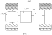
- the electric apparatus of an embodiment of this application being a vehicle 1000 is used as an example for description of the following embodiments.
- FIG. 1 is a schematic structural diagram of a vehicle 1000 according to some embodiments of this application.
- the vehicle 1000 may be a fossil fuel vehicle, a natural-gas vehicle, or a new energy vehicle, where the new energy vehicle may be a battery electric vehicle, a hybrid electric vehicle, a range-extended vehicle, or the like.
- the vehicle 1000 is provided with a battery 100 inside, where the battery 100 may be arranged at the bottom, front, or rear of the vehicle 1000.
- the battery 100 may be configured to supply power to the vehicle 1000.
- the battery 100 may be used as an operational power supply for the vehicle 1000.
- the vehicle 1000 may further include a controller 200 and a motor 300, where the controller 200 is configured to control the battery 100 to supply power to the motor 300, for example, to satisfy power needs of start, navigation, and driving of the vehicle 1000.
- the battery 100 can be used as not only the operational power source for the vehicle 1000 but also a driving power source for the vehicle 1000, replacing or partially replacing fossil fuel or natural gas to provide driving traction for the vehicle 1000.
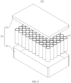
- FIG. 2 is an exploded view of a battery 100 according to some embodiments of this application.
- the battery 100 includes a battery cell 10 and a box assembly 20.
- the box assembly 20 is configured to provide an accommodating space for the battery cell 10.
- the box assembly 20 may be a variety of structures.
- the box assembly 20 may include a box 21 and a cover 22, where the box 21 and the cover 22 fit together to jointly define a space for accommodating the battery cell 10.
- the box 21 may be a hollow structure with an opening 2111 at one end to form an accommodating cavity for accommodating the battery cell 10
- the cover 22 may be a plate-like structure, and the cover 22 covers the opening side of the box 21, so that the box 21 and the cover 22 jointly define an accommodating space; or the box 21 and the cover 22 may be a hollow structure with an opening 2111 at one side to form an accommodating cavity for accommodating the battery cell 10, and the opening side of the box 21 covers the opening side of the cover 22.
- the box assembly 20 formed by the box 21 and the cover 22 may be a variety of shapes, for example, a cylinder or a cuboid. FIG. 2 , FIG. 3, and FIG.
- the battery cell 10 may be provided in plurality, and the plurality of battery cells 10 may be connected in series, parallel, or series-parallel, where being connected in series-parallel means a combination of series and parallel connections of the plurality of battery cells 10.
- the plurality of battery cells 10 may be directly connected in series, parallel, or series-parallel, and then an entirety of the plurality of battery cells 10 is accommodated in the box assembly 20; or certainly, the battery 100 may be formed by a plurality of battery cells 10 connected in series, parallel, or series-parallel first to form a battery module and then a plurality of battery modules being connected in series, parallel, or series-parallel to form an entirety which is accommodated in the box assembly 20.
- the battery 100 may further include other structures.
- the battery 100 may further include a busbar configured to implement electrical connection between the plurality of battery cells 10.
- Each battery cell 10 may be a secondary battery 100 or a primary battery 100, and may be a lithium-sulfur battery 100, a sodium-ion battery 100, or a magnesium-ion battery 100, but is not limited thereto.
- the battery cell 10 may be cylindrical, flat, cuboid, or of other shapes.
- the mounting hole 2121 may alternatively be a through hole penetrating the end wall 2112.
- the box 21 further includes a mounting member 213 installed on the end wall 2112, where the mounting structure 212 is placed on the mounting member 213.
- One mounting member 213 may be provided with one mounting structure 212 or may be provided with a plurality of mounting structures 212.
- the mounting member 213 is welded to the end wall 2112.
- the mounting member 213 and the end wall 2112 are welded, which not only makes the connection easy, but also enables the connection between the mounting member 213 and the end wall 2112 to be stronger and provide greater load-bearing capacity.
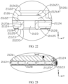
- a first weld seam 2124 is formed between the mounting member 213 and the end wall 2112, and the first weld seam 2124 is located on an outer side face 21121 of the end wall.
- the outer side face 21121 of the end wall with the first weld seam 2124 formed refers to a surface of a region of the end wall 2112 that overlaps with the mounting member 213 and that is farthest away from the battery cell 10 along the thickness direction X of the end wall.
- the first weld seam 2124 is a welding mark formed by welding the mounting member 213 and the end wall 2112.
- the first weld seam 2124 may be in various forms.
- the first weld seam 2124 may include a plurality of first welding marks, the plurality of first welding marks being spaced apart from each other around the periphery of the mounting member 213.
- the mounting member 213 is welded to the end wall 2112 at a plurality of positions in the circumferential direction, which enhances the connection stability.
- the first weld seam 2124 is a closed-loop structure that extends in the circumferential direction of the mounting member 213 and is closed in the circumferential direction of the mounting member 213.
- the first weld seam 2124 is located on the outer side face 21121 of the end wall, and the end wall 2112 and the mounting member 213 can be welded on the outer side of the end wall 2112, which makes the welding between the end wall 2112 and the mounting member 213 more convenient.
- the mounting member 213 may be directly connected to the outer side face 21121 of the end wall.
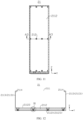
- the end wall 2112 may be further provided with a first installing hole 2123, where along the thickness direction X of the end wall, the first installing hole 2123 is recessed from the outer side face 21121 of the end wall to a direction close to the battery cell 10 (not shown in FIG. 13 ), and the first installing hole 2123 is recessed from the outer side face 21121 of the end wall to the interior of the box body 211.
- the mounting member 213 is at least partially inserted into the first installing hole 2123, so that the mounting member 213 and the end wall 2112 share at least part of the space along the thickness direction X of the end wall, which can reduce the size of the overall structure formed by the box body 211 and the mounting member 213 in the thickness direction X of the end wall.
- the first installing hole 2123 may be a circular hole, a square hole, a hexagonal hole, or the like, which is not limited in this application.
- the first installing hole 2123 may be a blind hole that does not penetrate through the two sides of the end wall 2112 along the thickness direction of the end wall 2112.
- the first installing hole 2123 may alternatively be a through hole penetrating the two sides of the end wall 2112 in the thickness direction X of the end wall.
- the first installing hole 2123 may alternatively be a stepped hole.
- FIG. 13, FIG. 14 , and FIG. 15 show the first installing hole 2123 being a stepped hole.
- the first installing hole 2123 includes a first hole segment 21231 and a second hole segment 21232 that communicate along the thickness direction X of the end wall.
- a projection of the first hole segment 21231 falls in the second hole segment 21232, and under the condition that both the first hole segment 21231 and the second hole segment 21232 are circular holes, a diameter of the second hole segment 21232 is larger than that of the first hole segment 21231.
- the second hole segment 21232 is closer to the interior of the box body 211 than the first hole segment 21231, or the second hole segment 21232 is closer to the battery cells 10 in the box 21 than the first hole segment 21231 (not shown in FIG. 13 to FIG. 15 ).
- the mounting member 213 may have a stepped structure matching the stepped hole. As shown in FIG. 13 , the mounting member 213 includes a first connecting segment 21221 and a second connecting segment 21222 connected along the thickness direction X of the end wall, where the outer profile of a projection of the second connecting segment 21222 in a plane perpendicular to the thickness direction X of the end wall surrounds the outer profile of a projection of the first connecting segment 21221 in a plane perpendicular to the thickness direction X of the end wall. In the embodiment where both the first connecting segment 21221 and the second connecting segment 21222 are cylindrical structures, the outer diameter of the second connecting segment 21222 is larger than that of the first connecting segment 21221.
- the first connecting segment 21221 is at least partially inserted into the first hole segment 21231
- the second connecting segment 21222 is at least partially inserted into the second hole segment 21232.
- An end surface of the second connecting segment 21222 connected to the first connecting end abuts against a surface where the first hole segment 21231 is connected to the second hole segment 21232.
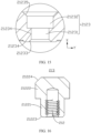
- the first tapered surface 21233 is opposite part of the outer peripheral surface of the mounting member 213, and a first welding space is formed between the first tapered surface 21233 and the outer peripheral surface of the mounting member 213, and along the thickness direction X of the end wall, the first weld seam 2124 is at least partially located in the first welding space, which can reduce the size of the first weld seam 2124 protruding from the outer side face 21121 of the end wall along the thickness direction X of the end wall or can prevent the first weld seam 2124 from protruding from the outer side face 21121 of the end wall along the thickness direction X of the end wall.
- the part of the outer peripheral surface of the mounting member 213 opposite the first tapered surface 21233 may alternatively be a first tapered surface 21223 for welding, and a large end of the first tapered surface 21223 for welding is arranged far away from the battery cell 10, so that a V-shaped first welding space is formed between the first tapered surface 21233 and the outer peripheral surface (first tapered surface 21223 for welding) of the mounting member 213.
- the first tapered surface 21233 is part of the wall surface of the first hole segment 21231, and the first tapered surface 21223 for welding is at least part of the outer peripheral surface of the first connecting segment 21221 of the mounting member 213.
- the first tapered surface 21233 may be a conical surface or a pyramid surface, and the first tapered surface 21223 for welding may be a conical surface or a pyramid surface.
- a second weld seam 2125 is formed between the mounting member 213 and the end wall 2112, and the second weld seam 2125 is located on an inner side face 21122 of the end wall.
- the inner side face 21122 of the end wall with the second weld seam 2125 is a surface of the end wall 2112 closest to the battery cell 10 in a region of the end wall 2112 overlapping the mounting member 213 in the thickness direction X of the end wall.
- the second weld seam 2125 is a welding mark formed by welding the mounting member 213 and the end wall 2112.
- the second weld seam 2125 may be in various forms.
- the second weld seam 2125 may include a plurality of second welding marks, the plurality of second welding marks being spaced apart from each other around the periphery of the mounting member 213.
- the mounting member 213 is welded to the end wall 2112 at a plurality of positions in the circumferential direction, which enhances the connection stability.
- the second weld seam 2125 is a closed-loop structure that extends in the circumferential direction of the mounting member 213 and is closed in the circumferential direction of the mounting member 213.
- the mounting member 213 is welded to the end wall 2112 at any position in the circumferential direction of the mounting member 213, which not only connects the end wall 2112 and the mounting member 213, but also acts as a seal, reducing the risk of foreign substances entering the gap between the end wall 2112 and the mounting member 213 and leakage of the box 21.
- the wall surface of the first installing hole 2123 includes a second tapered surface 21235, where a large end of the second tapered surface 21235 is connected to the inner side face 21122 of the end wall, and a small end of the second tapered surface 21235 is arranged close to an end of the first cylindrical surface 21234.
- the second tapered surface 21235 is opposite part of the outer peripheral surface of the mounting member 213, and a second welding space is formed between the second tapered surface 21235 and the outer peripheral surface of the mounting member 213, and along the thickness direction X of the end wall, the second weld seam 2125 is at least partially located in the second welding space, which can reduce the size of the second weld seam 2125 protruding from the inner side face 21122 of the end wall along the thickness direction X of the end wall or can prevent the second weld seam 2125 from protruding from the inner side face 21122 of the end wall along the thickness direction X of the end wall.
- the part of the outer peripheral surface of the mounting member 213 opposite the second tapered surface 21235 may alternatively be a second tapered surface 21224 for welding, and a large end of the second tapered surface 21224 for welding is arranged close to the battery cell 10, so that a V-shaped second welding space is formed between the second tapered surface 21235 and the outer peripheral surface (second tapered surface 21224 for welding) of the mounting member 213.
- the second tapered surface 21235 is part of the wall surface of the second hole segment 21232, and the second tapered surface 21224 for welding is at least part of the outer peripheral surface of the second connecting segment 21222 of the mounting member 213.
- the second tapered surface 21235 may be a conical surface or a pyramid surface, and the second tapered surface 21224 for welding may be a conical surface or a pyramid surface.
- the mounting member 213 and the end wall 2112 are welded to form the second weld seam 2125 on the inner side of the end wall 2112, and the mounting member 213 and the end wall 2112 are welded to form the second weld seam 2125 on the outer side of the end wall 2112, so there are two welding positions between the end wall 2112 and the mounting member 213, which further enhances the connection strength between the end wall 2112 and the mounting member 213.
- first weld seam 2124 and the second weld seam 2125 are both closed-loop structures along the circumferential direction of the mounting member 213, a two-layer welding seal is formed between the end wall 2112 and the mounting member 213, which improves the sealing performance between the end wall 2112 and the mounting member 213.
- the outer surface 21123 of the end wall is a surface of the end wall 2112 farthest away from the interior of the box body 211 along the thickness direction X of the end wall.
- the outer side face 21121 of the end wall and the outer surface 21123 of the end wall may be the same surface. In some other embodiments, the outer side face 21121 of the end wall and the outer surface 21123 of the end wall may alternatively be different surfaces.
- An end of the mounting member 213 facing away from the interior of the box body 211 may be flush with the outer surface 21123 of the end wall or may protrude from the outer surface 21123 of the end wall.
- the mounting structure 212 includes a plurality of mounting members 213, one end of all the mounting members 213 facing the exterior of the box body 211 in the thickness direction X of the end wall may be coplanar, which is conducive to the cooperation of all the mounting members 213 with the device.
- One end of the mounting member 213 is flush with the outer surface 21123 of the end wall, which can avoid the mounting member 213 exceeding the outer surface 21123 of the end wall to occupy the external space of the end wall 2112, thereby further reducing the volume of the box 21.
- One end of the mounting member 213 protrudes from the outer surface 21123 of the end wall, making it convenient for the mounting member 213 to engage with the device to connect the box body 211 and the device.
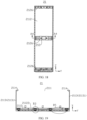
- the box 21 further includes a partition beam 2126, where the partition beam 2126 is located in the box body 211 and arranged on the end wall 2112, and when viewed in the thickness direction X of the end wall, the mounting structure 212 overlaps with the partition beam 2126.
- the partition beam 2126 may be fixed to the end wall 2112, for example, the partition beam 2126 is welded to the inner surface of the end wall 2112.
- the partition beam 2126 may alternatively be detachably connected to the end wall 2112, for example, the partition beam 2126 is connected to the end wall 2112 through bolts and screws.
- the mounting member 213 may be connected to the partition beam 2126, or may not be connected to the partition beam 2126.
- the partition beam 2126 is arranged in the box body 211, the partition beam 2126 is arranged on the end wall 2112, and when viewed in the thickness direction X of the end wall, the mounting structure 212 overlaps with the partition beam 2126, so that the partition beam 2126 can enhance the structural strength of a region of the end wall 2112 corresponding to the mounting structure 212, which reduces the risk of damage of the end wall 2112 due to overload.
- the mounting structure 212 includes a mounting member 213 installed on the end wall 2112, where one part of the mounting member 213 is embedded in the end wall 2112, and another part of the mounting member 213 is connected to the partition beam 2126.
- the first installing hole 2123 on the end wall 2112 is a through hole penetrating the two sides of the end wall in the thickness direction X, and the mounting member 213 penetrates through the first installing hole 2123, so that the mounting member 213 penetrates through the end wall 2112 and is connected to the partition beam 2126.
- the mounting member 213 and the partition beam 2126 can be fixedly connected through, for example, bonding and welding.
- the mounting member 213 and the partition beam 2126 may alternatively be detachably connected through, for example, bolts and screws.
- the mounting member 213 is embedded in the end wall 2112, and another part of the mounting member 213 is connected to the partition beam 2126, so that the end wall 2112 and the mounting member 213 share space, which reduces the external space of the box body 211 occupied by the mounting member 213 or avoids the mounting member 213 occupying the external space of the box body 211, thereby reducing the overall structural size of the box 21.
- the mounting member 213 is connected to the end wall 2112 and the partition beam 2126, and when the mounting member 213 connects the box body 211 to the device, the end wall 2112 and the partition beam 2126 can jointly bear the weight of the box body 211 and its internal structure, which reduces the risk of fatigue damage of the end wall 2112.
- the mounting member 213 is welded to the partition beam 2126.
- the mounting member 213 and the partition beam 2126 may be welded through laser welding, ultrasonic welding, resistance welding, and gas welding.
- the mounting member 213 and the partition beam 2126 are welded, which not only makes the connection easy, but also enables the connection between the mounting member 213 and the partition beam 2126 to be stronger and provide greater load-bearing capacity.
- a third weld seam 2134 is formed between the mounting member 213 and the partition beam 2126, and the third weld seam 2134 is located on the side of the partition beam 2126 facing away from the end wall 2112.
- the third weld seam 2134 is a welding mark formed by welding the mounting member 213 and the partition beam 2126.
- the third weld seam 2134 may be in various forms.
- the third weld seam 2134 may include a plurality of third welding marks, the plurality of third welding marks being spaced apart from each other around the periphery of the mounting member 213.
- the mounting member 213 is welded to the partition beam 2126 at a plurality of positions in the circumferential direction, which enhances the connection stability.
- the third weld seam 2134 is a closed-loop structure that extends in the circumferential direction of the mounting member 213 and is closed in the circumferential direction of the mounting member 213.
- the mounting member 213 is welded to the partition beam 2126 at any position in the circumferential direction of the mounting member 213, which not only connects the partition beam 2126 and the mounting member 213, but also acts as a seal, reducing the risk of impurities entering the gap between the partition beam 2126 and the mounting member 213.
- the partition beam 2126 is provided with a second installing hole 21261, and one part of the partition beam 2126 is inserted into the second installing hole 21261.
- the second installing hole 21261 may alternatively be a through hole penetrating the two sides of the partition beam 2126 in the thickness direction X of the end wall.
- the mounting member 213 is inserted into the second installing hole 21261.
- the wall surface of the second installing hole 21261 includes a third tapered surface 21262 and a third cylindrical surface 21263.
- a large end of the third tapered surface 21262 is connected to the surface of the partition beam 2126 facing away from the end wall 2112 in the thickness direction X of the end wall, and a small end of the third tapered surface 21262 is connected to an end of the third cylindrical surface 21263.
- the third tapered surface 21262 is opposite part of the outer peripheral surface of the mounting member 213, and a third welding space is formed between the third tapered surface 21262 and the outer peripheral surface of the mounting member 213, and along the thickness direction X of the end wall, the third weld seam 2134 is at least partially located in the third welding space, which can reduce the size of the third weld seam 2134 protruding from the surface of the partition beam 2126 facing away from the end wall 2112 along the thickness direction X of the end wall or can prevent the third weld seam 2134 from protruding from the surface of the partition beam 2126 along the thickness direction X of the end wall.
- the second installing hole 21261 may be a blind hole that does not penetrate through a side of the partition beam 2126 facing away from the end wall 2112 in the thickness direction X of the end wall.
- the structure of the end wall 2112 can not only be a solid plate-like structure.
- the flow channel 21124 formed inside the end wall 2112 can accommodate the heat exchange medium, so that the end wall 2112 can play a role in adjusting the temperature of the internal structure of the box body 211, and there is no need to arrange a thermal management component in the box body 211, which improves the utilization of space inside the battery 100 equipped with such box 21 and is conducive to increasing the energy density of the battery 100 equipped with such box 21.
- the mounting structure 212 includes the mounting member 213, when viewed in the thickness direction X of the end wall, the mounting member 213 does not overlap with the flow channel 21124.
- the mounting member 213 is arranged to avoid the flow channel 21124, and the heat transfer medium in the flow channel 21124 does not come into contact with the mounting member 213.
- the mounting member 213 does not overlap with the flow channel 21124, and the mounting member 213 and the flow channel 21124 portion do not interfere with each other, which can avoid the heat exchange medium in the flow channel 21124 reducing the service life of the mounting member 213, and can also prevent the mounting member 213 from affecting the flow of the heat exchange medium in the flow channel 21124 and reducing the heat exchange efficiency.
- the box 21 further includes a first pipe 2131 and a second pipe 2132, where the first pipe 2131 and the second pipe 2132 both communicate with the flow channel 21124. Both the first pipe 2131 and the second pipe 2132 are both located in the box body 211.
- the inlet 2129 is arranged in the first pipe 2131 and the outlet 2130 is arranged in the second pipe 2132.
- the box 21 includes a partition beam 2126
- the first pipe 2131 and the second pipe 2132 both pass through the partition beam 2126 in a direction facing away from the end wall 2112.
- the first pipe 2131 and the second pipe 2132 may pass through the same partition beam 2126, or may pass through different partition beams 2126 respectively.
- the end wall 2112 may be provided with one flow channel 21124 or may be provided with a plurality of flow channels 21124. In the embodiment where the end wall 2112 is provided with one flow channel 21124, the end wall 2112 may be provided with only one inlet 2129 and one outlet 2130. In the embodiment where the end wall 2112 is provided with a plurality of flow channels 21124, the extending directions of the flow channels 21124 may be the same or different, and the flow channels 21124 may be independent of each other or connected in parallel.
- one flow channel 21124 may be correspondingly provided with one inlet 2129 and one outlet 2130, or all the flow channels 21124 may share one inlet 2129 and one outlet 2130.
- the end wall 2112 is provided with a plurality of outlets 2130.
- the plurality of outlets 2130 are spaced apart from each other on the end wall 2112.
- the box body 211 may include a plurality of second pipes 2132, where the plurality of second pipes 2132 are spaced apart from each other, and each second pipe 2132 is provided with one outlet 2130. As shown in FIG. 24 , the plurality of second pipes 2132 pass through the same partition beam 2126. The plurality of second pipes 2132 are spaced apart from each other along the extending direction of the partition beam 2126.
- All of the heat exchange medium in the flow channel 21124 can flow from the plurality of outlets 2130.
- the end wall 2112 may be provided with one inlet 2129 or may be provided with a plurality of inlets 2129.
- the number of inlets 2129 may be in a one-to-one correspondence with the number of outlets 2130.
- the end wall 2112 is provided with a plurality of outlets 2130, which is conducive to quickly discharging the heat exchange medium from the flow channel 21124, and when the heat exchange medium is a cooling medium, the heat inside the box 21 can be quickly taken away, thereby rapidly reducing the temperature inside the box 21.
- the box 21 includes a plurality of mounting structures 212, the plurality of mounting structures 212 being spaced apart from each other.
- each mounting structure 212 in the plurality of mounting structures 212 may be the same or may be different.
- each mounting structure 212 may include only a mounting hole 2121 provided on the end wall 2112, or each mounting structure 212 may be provided on a mounting hole 2121 on one mounting member 213, so that all of the mounting structures 212 are the same.
- some mounting structures 212 in the plurality of mounting structures 212 may be mounting holes 2121 arranged on the end wall 2112, and other mounting structures 212 may be mounting holes 2121 arranged on the mounting member 213, so that the mounting structures 212 are different.
- the box 21 includes a plurality of mounting structures 212 spaced apart from each other, where the plurality of mounting positions can be formed between the box body 211 and the device, which not only makes the connection between the box body 211 and the electric device more stable, but also can reduce the load borne by each mounting position.
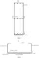
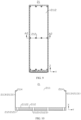
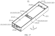
- the box body 211 further includes a side wall 2113, where the side wall 2113 surrounds an outer periphery of the end wall 2112, along a first direction Y, the side wall 2113 includes two oppositely arranged first side walls 21131, and the mounting member 213 does not extend beyond the outer side face of the first side wall 21131.
- the side wall 2113 surrounds the outer side of the end wall 2112, and can form a frame structure matching the outer contour of the end wall 2112. Along the thickness direction X of the end wall, one end of the side wall 2113 is connected to the end wall 2112, and another end forms an opening 2111 of the box body 211.
- the side wall 2113 may be an integrally formed structure surrounding the periphery of the end wall 2112, or may be a frame structure formed by connecting a plurality of plate-like structures in sequence along an edge of the end wall 2112.
- One end of the side wall 2113 may be directly or indirectly connected to an outer edge of the end wall 2112, for example, the side wall 2113 and the end wall 2112 are indirectly connected through glue.
- the side wall 2113 and the end wall 2112 may alternatively be integrally formed.
- the end wall 2112 and the side wall 2113 have different structural shapes, and the resulting box body 211 also has different structural shapes.
- the box body 211 is a rectangular structure; and if the end wall 2112 is a rectangular plate, the side wall 2113 includes only two first walls oppositely arranged along the first direction Y, and the two first walls are respectively connected to the two ends of the end wall 2112 along the first direction Y, the box body 211 has a U-shaped structure.
- the first direction y is any direction perpendicular to the thickness direction X of the end wall.
- the outer side face of the first side wall 21131 refers to a surface where the two first side walls 21131 face away from each other in the first direction Y.
- the side direction of the box body 211 in the embodiments of this application is any direction perpendicular to the thickness direction X of the end wall, and the first direction Y is one of side directions of the box body 211.
- the first direction Y may be parallel to a width direction of the vehicle 1000.
- the mounting member 213 does not exceed beyond the outer side face of the first side wall 21131, and therefore along the first direction Y, the mounting member 213 does not extend to the side direction of the box body 211, and the mounting member 213 does not occupy the space of the box body 211 outside the first side wall 21131.
- the size of the internal space of the box body 211 along the first direction Y can be increased so that the space of the box body 211 originally occupied by the mounting member 213 on the first direction Y can be used for accommodating battery cells 10, which is conducive to increasing the energy density and pack assembly efficiency of batteries 100 equipped with such box 21.
- the box 21 includes a first flange portion 2114, where the first flange portion 2114 is arranged at an end of the first side wall 21131 far away from the end wall 2112, and the first flange portion 2114 at least partially protrudes from the inner side face of the side wall 2113.
- the first flange portion 2114 is connected to an end of the side wall 2113 facing away from the end wall 2112.
- the surface of the first flange portion 2114 facing away from the end wall 2112 is formed with a connecting surface and a sealing surface that engage with the cover 22.
- the inner side face of the side wall 2113 refers to a surface of the side wall 2113 facing the interior of the box body 211.
- the inner side face of the first side wall 21131 refers to a surface of the first side wall 21131 facing another first side wall 21131, and the inner side face of the first side wall 21131 is at least part of the inner side face of the side wall 2113.
- the first flange portion 2114 may all protrude from the inner side face of the side wall 2113, that is, the first flange portion 2114 protrudes from the inner side face of the side wall 2113 to the interior of the box body 211 along the first direction Y. As shown in FIG. 21 , the first flange portion 2114 wholly protrudes from the inner side face of the side wall 2113.
- the two first side walls 21131 each are provided with the first flange portion 2114, and the first flange portion 2114 wholly protrudes from the inner side face of the corresponding first side wall 21131.
- only one part of the first flange portion 2114 may protrude from the inner surface of the side wall 2113, and another part of the first flange portion 2114 may protrude from an outer side face of the side wall 2113.
- the first flange portion 2114 Compared with the situation that the first flange portion 2114 wholly protrudes from the outer side face of the side wall 2113, the first flange portion 2114 at least partially protrudes from the inner side face of the side wall 2113, so that the box body 211 and the first flange portion 2114 share part of space, which can reduce the external space occupied by the first flange portion 2114 along the side direction of the box body 211.
- the size of the internal space of the box body 211 along the side direction of the box body 211 can be increased so that the space of the box body 211 originally occupied by the mounting member 213 on the side direction of the box body 211 can be used for accommodating battery cells 10, which is conducive to increasing the energy density and pack assembly efficiency of batteries 100 equipped with such box 21.
- the side wall 2113 further includes a second side wall 21132 and a third side wall 21133 oppositely arranged along the second direction Z.
- the box 21 includes a second flange portion 2115 and a third flange portion 2116.
- the second flange portion 2115 is arranged at an end of the second side wall 21132 far away from the end wall 2112 and at least partially protrudes from an inner side face of the second side wall 21132.
- the third flange portion 2116 is arranged at an end of the third side wall 21133 far away from the end wall 2112 and at least partially protrudes from an outer side face of the second side wall 21132.
- the first direction Y, the second direction Z, and the thickness direction X of the end wall are perpendicular to each other.
- the second direction Z is one of the side directions of the box body 211.
- the second flange portion 2115 is connected to an end of the second side wall 21132 facing away from the end wall 2112.
- the surface of the second flange portion 2115 facing away from the end wall 2112 is formed with a connecting surface and a sealing surface that engage with the cover 22.
- the inner side face of the second side wall 21132 refers to a surface of the second side wall 21132 facing the interior of the box body 211.
- the inner side face of the second side wall 2113 is part of the inner side face of the side wall 2113.
- the second flange portion 2115 may all protrude from the inner side face of the second side wall 21132, that is, the second flange portion 2115 protrudes from the inner side face of the second side wall 21132 to the interior of the box body 211 along the second direction Z. As shown in FIG. 25 , the second flange portion 2115 wholly protrudes from the inner side face of the second side wall 21132.
- only one part of the second flange portion 2115 may protrude from the inner surface of the second side wall 21132, and another part of the second flange portion 2115 may protrude from the outer side face of the second side wall 21132.
- the outer side face of the third side wall 21133 refers to a surface of the third side wall 21133 facing away from the interior of the box body 211.
- the third flange portion 2116 may all protrude from an outer side face of the third side wall 21133, that is, the third flange portion 2116 protrudes from the outer side face of the third side wall 21133 to the exterior of the box body 211 along the second direction Z.
- the third flange portion 2116 wholly protrudes from the outer side face of the third side wall 21133.
- only one part of the third flange portion 2116 may protrude from the outer side face of the third side wall 21133, and another part of the third flange portion 2116 may protrude from an inner side face of the third side wall 21133.
- the third flange portion 2116 protrudes toward the outside of the box body 211 along the second direction Z, and can share a certain space with other structures arranged on the outer side of the box body 211 along the second direction Z, which not greatly affects the overall size of the box 21, also makes the opening 2111 of the box body 211 larger, and is convenient for the battery cells 10 to be put into the box.
- the box body 211 further includes a side wall 2113, where the side wall 2113 surrounds an outer periphery of the end wall 2112, the side wall 2113 is provided with a hoisting structure 2133, and the hoisting structure 2133 is configured to engage with hoisting gear to move the box 21.
- the hoisting structure 2133 may be arranged at any part of the side wall 2113.
- the hoisting structure 2133 is arranged on the first side wall 21131, one of the two first side walls 21131 is provided with the hoisting structure 2133, or the two first side walls 21131 each are provided with the hoisting structure 2133.
- the hoisting structure 2133 includes the first hoisting hole 21331, and the first hoisting hole 21331 engages with the hoisting gear to lock the hoisting gear to the box body 211, which is conducive to moving the box 21 through engagement of the box 21 and the hoisting gear.
- arranging the first hoisting hole 21331 on the side wall 2113 can avoid occupying the external space of the box 21 in the side direction.
- the two second hoisting holes 21332 are located on the two sides of the first hoisting hole 21331 along the second direction Z, where the thickness direction X, the first direction Y, and the second direction Z of the end wall are perpendicular to each other.
- the second direction Z is parallel to a running direction of the vehicle 1000.
- the second hoisting holes 21332 are respectively arranged on the two sides of the first hoisting hole 21331, which can further accurately position the hoisting gear and the first hoisting hole 21331, so that the hoisting gear can be accurately locked to the box body 211 at the first hoisting hole 21331.
- the hoisting structure 2133 may alternatively include one second hoisting hole 21332 or may include three or more than three second hoisting holes 21332.
- first hoisting hole 21331 and the second hoisting hole 21332 may alternatively be in other structural forms.
- the side wall 2113 is provided with a plurality of hoisting structures 2133, the plurality of hoisting structures 2133 being spaced apart from each other.
- each first side wall 21131 may be provided with a plurality of hoisting structures 2133, the plurality of hoisting structures 2133 being spaced apart from each other along the second direction Z.
- the side wall 2113 is provided with a plurality of hoisting structures 2133 spaced apart from each other, and the hoisting gear can engage with the plurality of hoisting structures 2133, or the plurality of hoisting gears can engage with the plurality of hoisting structures 2133 to move the box 21, which can enhance the stability of hoisting operations.
- An embodiment of this application further provides a box assembly 20, where the box assembly 20 includes a cover 22 and the box 21 according to any one of the foregoing embodiments, and the cover 22 is configured to cover the opening 2111.
- the mounting member 213 of the box 21 occupies little or no external space in the side direction of the box body 211, so the box assembly 20 equipped with such box 21 can provide, by increasing the size of the internal space of the box body 211 along the side direction of the box body 211, the space of the box body 211 originally occupied by the mounting member 213 on the side direction of the box body 211 for accommodating battery cells 10, which is conducive to increasing the energy density and pack assembly efficiency of batteries 100 equipped with such box assembly 20.
- the box body 211 may not be provided with a side wall 2113, and the box body 211 includes only the end wall 2112.
- a battery cell 10 (not shown in FIG. 27 ) may be arranged on a side of the end wall 2112, and the end wall 2112 may bear the weight of the battery cell 10.
- the opening 2111 of the box body 211 may allow the battery cell 10 to be placed on any side of the end wall 2112, for example, in a space on the opposite side of the end wall 2112 along the thickness direction X of the end wall.
- the partition beam 2126 is arranged on a side of the end wall 2112 where the battery cell 10 is arranged, and the mounting structure 212 can penetrate through the partition beam 2126 along the thickness direction X of the end wall.
- each of the two opposite side faces of the end wall 2112 along the first direction Y may be provided with the hoisting structure 2133, or either of the two side faces of the end wall 2112 along the first direction Y may be provided with a plurality of hoisting structures 2133 spaced apart from each other along the second direction.
- two blocking portions 2135 may also be respectively arranged on the two sides of the end wall 2112.
- the blocking portions 2135 extend in the second direction Z and protrude from a surface of the end wall 2112 provided with the partition beam 2126 along the thickness direction X of the end wall.
- the blocking portions 2135 protrude from a surface of the end wall 2112 facing the battery cell 10 along the thickness direction X of the end wall.
- the blocking portion 2135 is configured to block the glue on the surface of the end wall 2112 from overflowing, where the glue includes but is not limited to a glue that bonds the battery cell 10 and the end wall 2112, a glue that bonds the partition beam 2126 and the end wall 2112, and the like.
- An embodiment of this application further provides a battery 100, where the battery 100 includes a battery cell 10 and the box assembly 20 according to the foregoing embodiments, and the battery cell 10 is accommodated in the box body 211.
- the internal space of the box assembly 20 can accommodate more battery cells 10, and batteries 100 equipped with such box assembly 20 can have relatively high energy density and pack assembly efficiency.
- An embodiment of this application further provides an electric device including the battery 100 according to the foregoing embodiments.
- An embodiment of this application provides a box 21, where the box 21 includes a box body 211 and a mounting member 213, the box body 211 includes an end wall 2112 and a side wall 2113, and the side wall 2113 surrounds an outer periphery of the end wall 2112.
- the mounting member 213 is a sleeve provided on the end wall 2112, and the sleeve has internal threads.
- the side wall 2113 includes two first side walls 21131 oppositely arranged along a first direction Y, and a second side wall 21132 and a third side wall 21133 oppositely arranged along a second direction Z.
- the mounting member 213 does not extend beyond an outer side face of the first side wall 21131 of the side wall 2113 in the first direction Y.
- An end of the first side wall 21131 facing away from the end wall 2112 is connected to a first flange portion 2114, and the first flange portion 2114 wholly protrudes from an inner side face of the first side wall 21131.
- An end of the second side wall 21132 facing away from the end wall 2112 is connected to a second flange portion 2115, and the second flange portion 2115 wholly protrudes from an inner side face of the second side wall 21132.
- An end of the third side wall 21133 facing away from the end wall 2112 is connected to a third flange portion 2116, and the third flange portion 2116 wholly protrudes from an outer side face of the third side wall 21133.
- An outer surface 21123 of the end wall is provided with an installation groove 21125, a protective structure 2128 is arranged in the installation groove 21125, and the protective structure 2128 does not extend beyond the groove.
- the first side wall 21131 is provided with a hoisting structure 2133, where the hoisting structure 2133 includes a first hoisting hole 21331 and two second hoisting holes 21332 located at two sides of the first hoisting hole 21331.
- the first hoisting hole 21331 is a threaded hole, and the second hoisting holes 21332 are waist-shaped holes.
Landscapes
- Chemical & Material Sciences (AREA)
- Chemical Kinetics & Catalysis (AREA)
- Electrochemistry (AREA)
- General Chemical & Material Sciences (AREA)
- Engineering & Computer Science (AREA)
- Manufacturing & Machinery (AREA)
- Aviation & Aerospace Engineering (AREA)
- Combustion & Propulsion (AREA)
- Transportation (AREA)
- Mechanical Engineering (AREA)
- Battery Mounting, Suspending (AREA)
Abstract
Description
- This application relates to the field of battery technologies, and in particular to a box, a box assembly, a battery, and an electric device.
- At present, batteries most commonly used in vehicles are lithium-ion batteries. As rechargeable batteries, lithium-ion batteries have the advantages of high energy density, high power density, long cycle life, long storage time, and so on.
- A battery typically includes a box and a battery cell, where the battery cell is accommodated in the box. Boxes with a larger volume are more conducive to increasing the energy density of batteries. However, boxes with a too large volume seriously restrict the pack assembly efficiency of batteries. Therefore, how the pack assembly efficiency of batteries is improved has become an urgent problem in the field of battery technologies.
- Embodiments of this application provide a box, a box assembly, a battery, and an electric device to improve the pack assembly efficiency of batteries.
- According to a first aspect, an embodiment of this application provides a box including a box body and a mounting structure; where the box body is provided with an opening and an end wall oppositely arranged; and the mounting structure is arranged on the end wall, and when viewed in a thickness direction of the end wall, the mounting structure overlaps with the end wall, and the mounting structure is configured to connect the box body and a device.
- In the above technical solution, the mounting structure is arranged on the end wall of the box, which can reduce the size of the part of the mounting structure extending to a side direction of the box body or prevent the mounting structure from extending to the side direction of the box body, thereby reducing the external space occupied by the mounting structure along the side direction of the box body or avoiding the mounting structure occupying the external space along the side direction of the box body. Thus, the size of the internal space of the box body along the side direction of the box body can be increased so that the space originally occupied by the mounting structure along the side direction of the box body can be used for accommodating battery cells, which is conducive to increasing the energy density and pack assembly efficiency of batteries equipped with such box.
- In some embodiments of the first aspect of this application, the mounting structure includes a mounting hole.
- In the above technical solution, the mounting member is a mounting hole arranged in the end wall, which is conducive to simplifying the structure and reducing the weight of the box.
- In some embodiments of the first aspect of this application, the mounting hole is provided with internal threads.
- In the above technical solution, the mounting hole is provided with internal threads, so that the device can threadedly engage with the mounting hole, thereby realizing the connection between the box body and the device. This connection method is simple and convenient and provides good stability.
- In some embodiments of the first aspect of this application, the mounting hole is a blind hole.
- In the above technical solution, the mounting hole is a blind hole, which means that the mounting hole does not penetrate through the end wall, thereby reducing the impact of arrangement of the mounting hole on the structural strength of the end wall. In addition, there is no need to seal the mounting hole, which reduces the manufacturing difficulty of the box.
- In some embodiments of the first aspect of this application, the box includes a mounting member installed on the end wall, where the mounting structure is arranged on the mounting member.
- In the above technical solution, the mounting structure is arranged on the mounting member installed on the end wall, and the box body and the device can be connected through the mounting member, which makes the connection between the box body and the device easier.
- In some embodiments of the first aspect of this application, the mounting member is welded to the end wall.
- In the technical solution, the mounting member and the end wall are welded, which not only makes the connection easy, but also enables the connection between the mounting member and the end wall to be stronger and provide greater load-bearing capacity.
- In some embodiments of the first aspect of this application, a first weld seam is formed between the mounting member and the end wall, and the first weld seam is located on an outer side face of the end wall.
- In the above technical solution, the first weld seam is located on the outer side face of the end wall, and the end wall and the mounting member can be welded on the outer side of the end wall, which makes the welding between the end wall and the mounting member more convenient.
- In some embodiments of the first aspect of this application, a second weld seam is formed between the mounting member and the end wall, and the second weld seam is located on an inner side face of the end wall.
- In the technical solution, the mounting member and the end wall are welded to form the second weld seam on the inner side of the end wall, and the mounting member and the end wall are welded to form the second weld seam on the outer side of the end wall, so there are two welding positions between the end wall and the mounting member, which further enhances the connection strength between the end wall and the mounting member.
- In some embodiments of the first aspect of this application, the mounting member is at least partially embedded in the end wall.
- In the technical solution, the mounting member is at least partially embedded in the end wall, so that the mounting member and the end wall share space in the thickness direction of the end wall, which reduces or avoids the external space of the box body occupied by the mounting member, thereby reducing the overall structural size of the box; and the mounting member is at least partially embedded in the end wall, which can increase the combined area between the mounting member and the end wall, thereby enhancing the connection stability between the end wall and the mounting member.
- In some embodiments of the first aspect of this application, one end of the mounting member is flush with the outer surface of the end wall; and/or one end of the mounting member protrudes from the outer surface of the end wall.
- In the technical solution, one end of the mounting member is flush with the outer surface of the end wall, which can avoid the mounting member exceeding the outer surface of the end wall to occupy the external space of the end wall, thereby further reducing the volume of the box. One end of the mounting member protrudes from the outer surface of the end wall, making it convenient for the mounting member to engage with the device to connect the box body and the device.
- In some embodiments of the first aspect of this application, the box further includes a partition beam, where the partition beam is located in the box body and arranged on the end wall, and when viewed in the thickness direction of the end wall, the mounting structure overlaps with the partition beam.
- In the above technical solution, the partition beam is arranged in the box body and on the end wall, and when viewed in the thickness direction of the end wall, the mounting structure overlaps with the partition beam, so that the partition beam can enhance the structural strength of a region of the end wall corresponding to the mounting structure, which reduces the risk of damage of the end wall due to overload.
- In some embodiments of the first aspect of this application, the mounting structure includes a mounting member installed on the end wall, where one part of the mounting member is embedded in the end wall, and another part of the mounting member is connected to the partition beam.
- In the above technical solution, one part of the mounting member is embedded in the end wall, and another part of the mounting member is connected to the partition beam, so that the end wall and the mounting member share space, which reduces the external space of the box body occupied by the mounting member or avoids the mounting member occupying the external space of the box body, thereby reducing the overall structural size of the box. The mounting member is connected to the end wall and the partition beam, and when the mounting member connects the box body to the device, the end wall and the partition beam can jointly bear the weight of the box body and its internal structure, which reduces the risk of fatigue damage of the end wall.
- In some embodiments of the first aspect of this application, the mounting member is welded to the partition beam.
- In the technical solution, the mounting member and the partition beam are welded, which not only makes the connection easy, but also enables the connection between the mounting member and the partition beam to be stronger and provide greater load-bearing capacity.
- In some embodiments of the first aspect of this application, a third weld seam is formed between the mounting member and the partition beam, and the third weld seam is located on a side of the partition beam facing away from the end wall.
- In the above technical solution, the third weld seam formed by welding the mounting member and the partition beam is located on the side of the partition beam facing away from the end wall, so that the welding of the mounting member and the partition beam can be carried out on the side of the partition beam facing away from the end wall, which makes the welding of the mounting member and the partition beam more convenient.
- In some embodiments of the first aspect of this application, the mounting member is a sleeve, and the sleeve is provided with internal threads.
- In the above technical solution, the mounting member is a sleeve, and the sleeve is provided with internal threads, so that the mounting member threadedly engages with the device to mount the box on the electric device. Such mounting method is simple and convenient, and provides good stability.
- In some embodiments of the first aspect of this application, a protective structure is provided on the outer side of the end wall, and the protective structure is configured to provide cushioning and/or insulation for the end wall.
- In the above technical solution, the arrangement of the protective structure can improve the impact resistance of the end wall and/or help to maintain a substantially constant ambient temperature inside the box.
- In some embodiments of the first aspect of this application, the mounting structure protrudes from the protective structure.
- In the technical solution, the mounting structure protrudes from the protective structure, which facilitates the engagement between the mounting structure and the device and reduces the risk of interference between the connecting position of the mounting structure and the device and the protective structure.
- In some embodiments of the first aspect of this application, a flow channel for accommodating a heat exchange medium is formed inside the end wall.
- In the above technical solution, the flow channel formed inside the end wall can accommodate the heat exchange medium, so that the end wall can play a role in adjusting the temperature of the internal structure of the box body, and there is no need to arrange a thermal management component in the box body, which improves the utilization of space inside the battery equipped with such box and is conducive to increasing the energy density of the battery equipped with such box.
- In some embodiments of the first aspect of this application, when viewed in the thickness direction of the end wall, the mounting member does not overlap with the flow channel.
- In the above technical solution, the mounting member does not overlap with the flow channel, and the mounting member and the flow channel do not interfere with each other, which can avoid the heat exchange medium in the flow channel reducing the service life of the mounting member, and can also prevent the mounting member from affecting the flow of the heat exchange medium in the flow channel and reducing the heat exchange efficiency.
- In some embodiments of the first aspect of this application, the end wall is provided with an inlet for the heat exchange medium to flow into the flow channel and an outlet for the heat exchange medium in the flow channel to flow out.
- In the above technical solution, the end wall is provided with the inlet and the outlet of the heat exchange medium, so that the heat exchange medium can flow in the flow channel, which can make heat exchange faster, thereby improving the heat exchange efficiency.
- In some embodiments of the first aspect of this application, the end wall is provided with a plurality of such outlets.
- In the above technical solution, the end wall is provided with a plurality of outlets, which is conducive to quickly discharging the heat exchange medium from the flow channel, and when the heat exchange medium is a cooling medium, the heat inside the box can be quickly taken away, thereby rapidly reducing the temperature inside the box.
- In some embodiments of the first aspect of this application, the box includes a plurality of such mounting structures, the plurality of mounting structures being spaced apart from each other.
- In the above technical solution, the box includes a plurality of mounting structures spaced apart from each other, where the plurality of mounting positions can be formed between the box body and the device, which not only makes the connection between the box body and the electric device more stable, but also can reduce the load borne by each mounting position.
- In some embodiments of the first aspect of this application, the box body further includes a side wall, where the side wall surrounds an outer periphery of the end wall, and in a first direction, the side wall includes two opposite first side walls, and the mounting member does not exceed beyond an outer side face of the first side wall.
- In the above technical solution, the structure of the mounting member does not exceed beyond the outer side face of the first side wall, and therefore along the first direction, the mounting member does not extend to the side direction of the box body, and the mounting member does not occupy the space of the box body outside the first side wall. Thus, the size of the internal space of the box body along the first direction can be increased so that the space of the box body originally occupied by the mounting member on the first direction can be used for accommodating battery cells, which is conducive to increasing the energy density and pack assembly efficiency of batteries equipped with such box.
- In some embodiments of the first aspect of this application, the box includes a first flange portion, where the first flange portion is arranged at one end of the first side wall away from the end wall, and the first flange portion at least partially protrudes from an inner side face of the side wall.
- In the above technical solution, compared with the situation that the first flange portion wholly protrudes from an outer side face of the side wall, the first flange portion at least partially protrudes from an inner side face of the side wall, so that the box body and the first flange portion share part of space, which can reduce the external space occupied by the first flange portion along a side direction of the box body. Thus, the size of the internal space of the box body along the side direction of the box body can be increased so that the space of the box body originally occupied by the mounting member on the side direction of the box body can be used for accommodating battery cells, which is conducive to increasing the energy density and pack assembly efficiency of batteries equipped with such box.
- In some embodiments of the first aspect of this application, the box body further includes a side wall, where the side wall surrounds an outer periphery of the end wall, the side wall is provided with a hoisting structure, and the hoisting structure is configured to engage with hoisting gear to move the box.
- In the technical solution, the arrangement of the hoisting structure facilitates the assembly and transport of the box.
- In some embodiments of the first aspect of this application, the hoisting structure includes a first hoisting hole, the first hoisting hole being configured to engage with the hoisting gear to lock the hoisting gear to the box body.
- In the above technical solution, the hoisting structure includes the first hoisting hole, and the first hoisting hole engages with the hoisting gear to lock the hoisting gear to the box body, which is conducive to move the box through engagement of the box and the hoisting gear. Compared with the situation that a hoisting member protruding from the outer side face of the side wall is installed on the side wall, arranging the first hoisting hole on the side wall can avoid occupying the external space of the box body in the side direction. Thus, the size of the internal space of the box body along the side direction of the box body can be increased so that the space of the box body originally occupied by the mounting member on the side direction of the box body can be used for accommodating battery cells, which is conducive to increasing the energy density and pack assembly efficiency of batteries equipped with such box.
- In some embodiments of the first aspect of this application, the hoisting structure includes a second hoisting hole, the second hoisting hole being configured for positional engagement with the hoisting gear.
- In the technical solution, the arrangement of the second hoisting hole can keep the hoisting gear and the box in relatively accurate positions before the hoisting gear is engaged with the first hoisting hole, so that the hoisting gear can accurately engage with the first hoisting hole to lock the hoisting gear to the box body.
- In some embodiments of the first aspect of this application, the hoisting structure includes two second hoisting holes, the two second hoisting holes being respectively located at two sides of the first hoisting hole.
- In the above technical solution, the second hoisting holes are respectively arranged on the two sides of the first hoisting hole, which can further accurately position the hoisting gear and the first hoisting hole, so that the hoisting gear can be accurately locked to the box body at the first hoisting hole.
- In some embodiments of the first aspect of this application, the first hoisting hole is a threaded hole; and/or the second hoisting hole is a waist-shaped hole.
- In the above technical solution, if the first hoisting hole is a threaded hole, the box body and the hoisting gear can be locked by the threaded engagement of the hoisting gear and the first hoisting hole. Such locking method is simple and convenient, and can improve the hoisting operation efficiency. If the second hoisting hole is a waist-shaped hole, after the hoisting gear comes into positional engagement with the second hoisting hole, the risk that the hoisting gear rotates in the second hoisting hole is relatively small, which can enhance the positioning stability.
- In some embodiments of the first aspect of this application, the side wall is provided with a plurality of such hoisting structures, the plurality of hoisting structures being spaced apart from each other.
- In the above technical solution, the side wall is provided with a plurality of hoisting structures spaced apart from each other, and the hoisting gear can engage with the plurality of hoisting structures, or a plurality of hoisting gears can engage with the plurality of hoisting structures to move the box, which can enhance the stability of hoisting operations.
- According to a second aspect, an embodiment of this application provides a box assembly, where the box assembly includes a cover and the box according to any one of the embodiments of the first aspect, and the cover is configured to cover the opening.
- In the above technical solution, the mounting member of the box according to embodiments of the first aspect occupies little or no external space in the side direction of the box body, so the box assembly equipped with such box can provide, by increasing the size of the internal space of the box body along the side direction of the box body, the space of the box body originally occupied by the mounting member on the side direction of the box body for accommodating battery cells, which is conducive to increasing the energy density and pack assembly efficiency of batteries equipped with such box assembly.
- According to a third aspect, an embodiment of this application further provides a battery including a battery cell and the box assembly according to the embodiments of the second aspect, where the battery cell is accommodated in the box body.
- In the above technical solution, the internal space of the box assembly according to the embodiments of the second aspect can accommodate more battery cells, and batteries equipped with such box assembly can have relatively high energy density and pack assembly efficiency.
- According to a fourth aspect, an embodiment of this application provides an electric device including the battery according to any one of the embodiments of the third aspect.
- To describe the technical solutions of the embodiments of this application more clearly, the following briefly describes the accompanying drawings required for describing the embodiments. It is appreciated that the accompanying drawings below show merely some embodiments of this application and thus should not be considered as limitations on the scope. Persons of ordinary skill in the art may still derive other related drawings from the accompanying drawings without creative efforts.
-
FIG. 1 is a schematic structural diagram of a vehicle according to some embodiments of this application; -
FIG. 2 is an exploded view of a battery according to some embodiments of this application; -
FIG. 3 is a schematic structural diagram of an assembled box assembly according to some embodiments of this application; -
FIG. 4 is an exploded view of a box assembly according to some embodiments of this application; -
FIG. 5 is a schematic structural diagram of a box according to some embodiments of this application; -
FIG. 6 is a schematic diagram of a box according to some embodiments of this application from another perspective; -
FIG. 7 is a view of a box according to some embodiments of this application as viewed from the opening side of the box body; -
FIG. 8 is a cross-sectional view taken along line A1-A1 inFIG. 7 ; -
FIG. 9 is a view of a box according to some other embodiments of this application as viewed from the opening side of the box body; -
FIG. 10 is a cross-sectional view taken along line A2-A2 inFIG. 9 ; -
FIG. 11 is a view of a box according to still some other embodiments of this application as viewed from the opening side of the box body; -
FIG. 12 is a cross-sectional view taken along line A3-A3 inFIG. 11 ; -
FIG. 13 is an enlarged view of a position B1 inFIG. 12 ; -
FIG. 14 is a schematic structural diagram of the box body inFIG. 12 ; -
FIG. 15 is an enlarged view of a position B2 inFIG. 14 ; -
FIG. 16 is a schematic structural diagram of a mounting member according to some embodiments of this application; -
FIG. 17 is a structural view of a box according to some other embodiments of this application; -
FIG. 18 is a view of a box according to yet some other embodiments of this application as viewed from the opening side of the box body; -
FIG. 19 is a cross-sectional view taken along line A4-A4 inFIG. 18 ; -
FIG. 20 is an enlarged view of a position B3 inFIG. 19 ; -
FIG. 21 is a schematic structural diagram of the box body inFIG. 19 ; -
FIG. 22 is an enlarged view of a position B4 inFIG. 21 ; -
FIG. 23 is an enlarged view of a position B5 inFIG. 19 ; -
FIG. 24 is a schematic structural diagram of a box body according to some other embodiments of this application; -
FIG. 25 is a cross-sectional view taken along line A5-A5 inFIG. 24 ; -
FIG. 26 is an enlarged view of a position B6 inFIG. 24 ; and -
FIG. 27 is a schematic structural diagram of a box according to some other embodiments of this application. - Reference signs: 1000: vehicle; 100: battery; 10: battery cell; 20: box assembly; 21: box; 211: box body; 2111: opening; 2112: end wall; 21121: outer side face of end wall; 21122: inner side face of end wall; 21123: outer surface of end wall; 21124: flow channel; 21125: installation groove; 2113: side wall; 21131: first side wall; 21132: second side wall; 21133: third side wall; 2114: first flange portion; 2115: second flange portion; 2116: third flange portion; 212: mounting structure; 2121: mounting hole; 213: mounting member; 21221: first connecting segment; 21222: second connecting segment; 21223: first tapered surface for welding; 21224: second tapered surface for welding; 2123: first installing hole; 21231: first hole segment; 21232: second hole segment; 21233: first tapered surface; 21234: first cylindrical surface; 21235: second tapered surface; 2124: first weld seam; 2125: second weld seam; 2126: partition beam; 21261: second installing hole; 21262: third tapered surface; 21263: third cylindrical surface; 21264: third hole segment; 21265: fourth hole segment; 2128: protective structure; 2129: inlet; 2130: outlet; 2131: first pipe; 2132: second pipe; 2133: hoisting structure; 21331: first hoisting hole; 21332: second hoisting hole; 2134: third weld seam; 2135: blocking portion; 22: cover; 23: sealing member; 200: controller; 300: motor; X: thickness direction of end wall; Y: first direction; and Z: second direction.
- To make the objectives, technical solutions, and advantages of the embodiments of this application clearer, the following clearly and completely describes the technical solutions in the embodiments of this application with reference to the accompanying drawings in the embodiments of this application. Apparently, the described embodiments are some but not all embodiments of this application. Generally, the components of the embodiments of this application as described and illustrated in the accompanying drawings herein can be arranged and designed in a variety of configurations.
- Therefore, the following detailed description of the embodiments of this application as provided in the accompanying drawings is not intended to limit the scope of this application but merely to represent selected embodiments of this application. All other embodiments obtained by persons of ordinary skill in the art based on the embodiments of this application without creative efforts shall fall within the protection scope of this application.
- It should be noted that, without conflict, the embodiments and features in the embodiments in this application may be combined with each other.
- It should be noted that similar reference numerals and letters indicate similar items in the following drawings, and therefore once an item is defined in one drawing, it does not need to be further defined or explained in the subsequent drawings.
- In the description of the embodiments of this application, it should be noted that the orientations or positional relationships as indicated are orientations or positional relationships based on the accompanying drawings, or conventional orientations or positional relationships of products of this application, or orientations or positional relationships as conventionally understood by persons skilled in the art, and the orientations or positional relationships as indicated are merely for ease and brevity of description of this application rather than indicating or implying that the apparatuses or elements mentioned must have specific orientations or must be constructed or manipulated according to specific orientations, and therefore cannot be understood as limitations on this application. In addition, the terms "first", "second", "third", and the like are merely intended for distinguishing purposes and shall not be understood as any indication or implication of relative importance.
- Currently, from a perspective of the market development, application of traction batteries is being more extensive. Traction batteries have been not only used in energy storage power supply systems such as hydroelectric power plants, thermal power plants, wind power plants, and solar power plants, but also widely used in many other fields including electric transportation tools such as electric bicycles, electric motorcycles, and electric vehicles, military equipment, and aerospace. With the continuous expansion of application fields of traction batteries, market demands for traction batteries are also increasing.
- The inventors have found that a battery includes a box assembly and a battery cell, the box assembly includes a box body and a mounting structure, and an electric device and the box body are engaged in a side direction of the box body through the mounting structure, which makes the mounting structure occupy a large space in the side direction of the box body, and consequently the box body cannot have its internal space size increased in its side direction, seriously restricting the pack assembly efficiency of batteries.
- Based on the above considerations, to improve the pack assembly efficiency of batteries, after in-depth research, the inventors have designed a box, where a box body of the box has an opening and an end wall arranged oppositely, a mounting structure of the box body is installed on the end wall of the box body, and when viewed in a thickness direction of the end wall, the mounting structure overlaps with the end wall.
- The mounting structure is arranged on the end wall of the box, which can reduce the size of the part of the mounting structure extending to a side direction of the box body or prevent the mounting structure from extending to the side direction of the box body, thereby reducing the external space occupied by the mounting structure along the side direction of the box body or avoiding the mounting structure occupying the external space along the side direction of the box body. Thus, the size of the internal space of the box body along the side direction of the box body can be increased so that the space originally occupied by the mounting structure along the side direction of the box body can be used for accommodating battery cells, which is conducive to increasing the energy density and pack assembly efficiency of batteries equipped with such box.
- An embodiment of this application provides an electric device that uses a battery as its power source. The electric device may be, but is not limited to, a mobile phone, a tablet, a laptop computer, an electric toy, an electric bicycle, an electric vehicle, a ship, or a spacecraft. The electric toy may be a fixed or mobile electric toy, for example, a game console, an electric toy car, an electric toy ship, and an electric toy airplane. The spacecraft may include an airplane, a rocket, a space shuttle, a spaceship, and the like.
- For ease of description, the electric apparatus of an embodiment of this application being a
vehicle 1000 is used as an example for description of the following embodiments. - Refer to
FIG. 1. FIG. 1 is a schematic structural diagram of avehicle 1000 according to some embodiments of this application. Thevehicle 1000 may be a fossil fuel vehicle, a natural-gas vehicle, or a new energy vehicle, where the new energy vehicle may be a battery electric vehicle, a hybrid electric vehicle, a range-extended vehicle, or the like. Thevehicle 1000 is provided with abattery 100 inside, where thebattery 100 may be arranged at the bottom, front, or rear of thevehicle 1000. Thebattery 100 may be configured to supply power to thevehicle 1000. For example, thebattery 100 may be used as an operational power supply for thevehicle 1000. Thevehicle 1000 may further include acontroller 200 and amotor 300, where thecontroller 200 is configured to control thebattery 100 to supply power to themotor 300, for example, to satisfy power needs of start, navigation, and driving of thevehicle 1000. - In some embodiments of this application, the
battery 100 can be used as not only the operational power source for thevehicle 1000 but also a driving power source for thevehicle 1000, replacing or partially replacing fossil fuel or natural gas to provide driving traction for thevehicle 1000. - Referring to
FIG. 2, FIG. 2 is an exploded view of abattery 100 according to some embodiments of this application. Thebattery 100 includes abattery cell 10 and abox assembly 20. Thebox assembly 20 is configured to provide an accommodating space for thebattery cell 10. Thebox assembly 20 may be a variety of structures. In some embodiments, thebox assembly 20 may include abox 21 and acover 22, where thebox 21 and thecover 22 fit together to jointly define a space for accommodating thebattery cell 10. Thebox 21 may be a hollow structure with anopening 2111 at one end to form an accommodating cavity for accommodating thebattery cell 10, thecover 22 may be a plate-like structure, and thecover 22 covers the opening side of thebox 21, so that thebox 21 and thecover 22 jointly define an accommodating space; or thebox 21 and thecover 22 may be a hollow structure with anopening 2111 at one side to form an accommodating cavity for accommodating thebattery cell 10, and the opening side of thebox 21 covers the opening side of thecover 22. Certainly, thebox assembly 20 formed by thebox 21 and thecover 22 may be a variety of shapes, for example, a cylinder or a cuboid.FIG. 2 ,FIG. 3, and FIG. 4 show thebox 21 being a hollow structure with an opening at one end and thecover 22 being a plate-like structure. A sealing member 23 may further be provided between thebox 21 and thecover 22, and thebox 21, thecover 22, and the sealing member 23 jointly form a closed space for accommodating thebattery cell 10. - In the
battery 100, thebattery cell 10 may be provided in plurality, and the plurality ofbattery cells 10 may be connected in series, parallel, or series-parallel, where being connected in series-parallel means a combination of series and parallel connections of the plurality ofbattery cells 10. The plurality ofbattery cells 10 may be directly connected in series, parallel, or series-parallel, and then an entirety of the plurality ofbattery cells 10 is accommodated in thebox assembly 20; or certainly, thebattery 100 may be formed by a plurality ofbattery cells 10 connected in series, parallel, or series-parallel first to form a battery module and then a plurality of battery modules being connected in series, parallel, or series-parallel to form an entirety which is accommodated in thebox assembly 20. Thebattery 100 may further include other structures. For example, thebattery 100 may further include a busbar configured to implement electrical connection between the plurality ofbattery cells 10. - Each
battery cell 10 may be asecondary battery 100 or aprimary battery 100, and may be a lithium-sulfur battery 100, a sodium-ion battery 100, or a magnesium-ion battery 100, but is not limited thereto. Thebattery cell 10 may be cylindrical, flat, cuboid, or of other shapes. - As shown in
FIG. 5 to FIG. 8 , in some embodiments, thebox 21 includes abox body 211 and a mountingstructure 212. Thebox body 211 has anopening 2111 and anend wall 2112 arranged oppositely. The mountingstructure 212 is arranged on theend wall 2112. when viewed in a thickness direction X of the end wall, the mountingstructure 212 overlaps with theend wall 2112, and the mountingstructure 212 is configured to connect thebox body 211 and a device. - The
end wall 2112 may be a plate-like structure. Theend wall 2112 may be in various shapes, for example, theend wall 2112 is a rectangular plate, a circular plate, or the like, which is not limited in this application. Theopening 2111 and theend wall 2112 of thebox body 211 are oppositely arranged along the thickness direction X of the end wall. Theopening 2111 of thebox body 211 allows thebattery cell 10 to enter the space formed by thebox body 211; or theopening 2111 of thebox body 211 may allow thebattery cell 10 to be placed on theend wall 2112, so that theend wall 2112 can support thebattery cell 10. - When viewed in the thickness direction X of the end wall, the mounting
structure 212 overlaps with theend wall 2112, which can be understood that a projection of the mountingstructure 212 at least partially overlaps in the thickness direction X of the end wall, so that theend wall 2112 and the mountingstructure 212 share at least part of the space when viewed in the thickness direction X of the end wall. - The mounting
structure 212 is configured to connect thebox body 211 and the device, where the device includes, but is not limited to, an electric device, a transportation device, a storage device. The mountingstructure 212 may be a through hole, a blind hole, a threaded hole, a hook, a slide rail, a guide rail, a lock, and other structures. The mountingstructure 212 may be a structure directly formed on theend wall 2112 and integrally formed with theend wall 2112. For example, the mountingstructure 212 is a threaded hole formed in theend wall 2112, or the mountingstructure 212 is a track integrally extruded with theend wall 2112, or the mountingstructure 212 may be formed on another component connected to theend wall 2112. For example, the mountingstructure 212 is a threaded hole on a component such as a sleeve, a nut, or a mounting beam, or the mountingstructure 212 is a track on a guide rail. - After the
battery 100 equipped withsuch box 21 is connected to the electric device, theend wall 2112 may be located in different directions with respect to thebattery cell 10. For example, theend wall 2112 may be located below thebattery cell 10 and support thebattery cell 10. In this case, theend wall 2112 is the bottom wall of thebox body 211 and bears at least part of the weight of thebattery cell 10. For another example, theend wall 2112 may alternatively be located above thebattery cell 10. In this case, theend wall 2112 is the top wall of thebox body 211. - The mounting
structure 212 is arranged on theend wall 2112 of thebox 21, which can reduce the size of the part of the mountingstructure 212 extending to a side of thebox body 211 or prevent the mountingstructure 212 from extending to a side direction of thebox body 211, thereby reducing the external space occupied by the mountingstructure 212 along the side direction of thebox body 211 or avoiding the mountingstructure 212 occupying the external space along the side direction of thebox body 211. Thus, the size of the internal space of thebox body 211 along the side direction of thebox body 211 can be increased so that the space originally occupied by the mountingstructure 212 along the side direction of thebox body 211 can be used for accommodatingbattery cells 10, which is conducive to increasing the energy density and pack assembly efficiency ofbatteries 100 equipped withsuch box 21. The side direction of thebox body 211 in this embodiment of this application is any direction perpendicular to the thickness direction X of the end wall. - The mounting
structure 212 may be in various forms. For example, as shown inFIG. 7 to FIG. 10 , in some embodiments, the mountingstructure 212 includes a mountinghole 2121. The mountinghole 2121 is directly arranged on theend wall 2112. Along the thickness direction X of the end wall, the mountinghole 2121 is recessed from a side of theend wall 2112 facing away from thebattery cell 10 towards a direction close to thebattery cell 10. The mountinghole 2121 may be a circular hole, a square hole, a hexagonal hole, or the like, which is not limited in this application. - The mounting
hole 2121 may be provided in one or in plural, and the plural means two or more than two. In this embodiment where there are a plurality of mountingholes 2121, the plurality of mountingholes 2121 being spaced apart from each other. - The mounting
structure 212 is a mountinghole 2121 arranged in theend wall 2112, which is conducive to simplifying the structure of thebox 21 and reducing the weight of thebox 21. - In some embodiments, the wall of the mounting
hole 2121 is a smooth or curved surface. - In some other embodiments, the mounting
hole 2121 may be provided with internal threads, and the internal threads are provided on the wall surface of the mountinghole 2121, so that the mountinghole 2121 is a threaded hole. - The mounting
hole 2121 is provided with the internal threads, so that the device can threadedly engage with the mountinghole 2121, thereby realizing the connection between thebox body 211 and the device. This connection method is simple and convenient and provides good stability. - As shown in
FIG. 8 , in some embodiments, the mountinghole 2121 is a blind hole. - The blind hole is a through hole connecting a surface layer and the inner layer without penetrating through the whole plate, that is, the mounting
hole 2121 does not penetrate through theend wall 2112, or the mountinghole 2121 does not extend to a side of theend wall 2112 facing thebattery cell 10 along the thickness direction X of the end wall. - Therefore, the mounting
hole 2121 is a blind hole, which means that the mountinghole 2121 does not penetrate through theend wall 2112, thereby reducing the impact of arrangement of the mountinghole 2121 on the structural strength of theend wall 2112. In addition, there is no need to seal the mountinghole 2121, which reduces the manufacturing difficulty of thebox 21. - As shown in
FIG. 9 and FIG. 10 , in some other embodiments, the mountinghole 2121 may alternatively be a through hole penetrating theend wall 2112. - As shown in
FIG. 11 to FIG. 13 , in some other embodiments, thebox 21 further includes a mountingmember 213 installed on theend wall 2112, where the mountingstructure 212 is placed on the mountingmember 213. - The mounting
member 213 and theend wall 2112 can be fixedly connected through, for example, bonding and welding. The mountingmember 213 and theend wall 2112 may alternatively be detachably connected through, for example, bolts and screws. The device is connected to thebox body 211 through the mountingmember 213. The mountingstructure 212 is indirectly arranged on theend wall 2112 through the mountingmember 213. The mountingmember 213 may be a structural member such as a mounting beam, a corner member, or a reinforcing plate. The mountingmember 213 may alternatively be a standard industrial member such as a sleeve, a nut, or a slide rail. A mounting structure such as a through hole, a threaded hole, or a slot can be processed in the mountingmember 213. The mountingmember 213 may alternatively be a connecting structure that comes with an industrial component. For example, when the mountingmember 213 is a nut, the mountingstructure 212 is a threaded hole on the nut. - The
box body 211 may include one mountingmember 213 or may include a plurality of mountingmembers 213. In the embodiment where thebox body 211 includes a plurality of mountingmembers 213, the plurality of mountingmembers 213 being spaced apart from each other on theend wall 2112. - One mounting
member 213 may be provided with one mountingstructure 212 or may be provided with a plurality of mountingstructures 212. - In some embodiments, the mounting
member 213 is welded to theend wall 2112. - The mounting
member 213 and theend wall 2112 may be welded through laser welding, ultrasonic welding, resistance welding, and gas welding. - The mounting
member 213 and theend wall 2112 are welded, which not only makes the connection easy, but also enables the connection between the mountingmember 213 and theend wall 2112 to be stronger and provide greater load-bearing capacity. - As shown in
FIG. 13 , in some embodiments, afirst weld seam 2124 is formed between the mountingmember 213 and theend wall 2112, and thefirst weld seam 2124 is located on anouter side face 21121 of the end wall. - The
outer side face 21121 of the end wall with thefirst weld seam 2124 formed refers to a surface of a region of theend wall 2112 that overlaps with the mountingmember 213 and that is farthest away from thebattery cell 10 along the thickness direction X of the end wall. Thefirst weld seam 2124 is a welding mark formed by welding the mountingmember 213 and theend wall 2112. - The
first weld seam 2124 may be in various forms. For example, thefirst weld seam 2124 may include a plurality of first welding marks, the plurality of first welding marks being spaced apart from each other around the periphery of the mountingmember 213. In this way, the mountingmember 213 is welded to theend wall 2112 at a plurality of positions in the circumferential direction, which enhances the connection stability. For another example, thefirst weld seam 2124 is a closed-loop structure that extends in the circumferential direction of the mountingmember 213 and is closed in the circumferential direction of the mountingmember 213. In this way, the mountingmember 213 is welded to theend wall 2112 at any position in the circumferential direction of the mountingmember 213, which not only connects theend wall 2112 and the mountingmember 213, but also acts as a seal, reducing the risk of foreign substances entering the gap between theend wall 2112 and the mountingmember 213. - The
first weld seam 2124 is located on theouter side face 21121 of the end wall, and theend wall 2112 and the mountingmember 213 can be welded on the outer side of theend wall 2112, which makes the welding between theend wall 2112 and the mountingmember 213 more convenient. - In some embodiments, the mounting
member 213 may be directly connected to theouter side face 21121 of the end wall. - In some other embodiments, the
end wall 2112 may be further provided with afirst installing hole 2123, where along the thickness direction X of the end wall, thefirst installing hole 2123 is recessed from theouter side face 21121 of the end wall to a direction close to the battery cell 10 (not shown inFIG. 13 ), and thefirst installing hole 2123 is recessed from theouter side face 21121 of the end wall to the interior of thebox body 211. The mountingmember 213 is at least partially inserted into thefirst installing hole 2123, so that the mountingmember 213 and theend wall 2112 share at least part of the space along the thickness direction X of the end wall, which can reduce the size of the overall structure formed by thebox body 211 and the mountingmember 213 in the thickness direction X of the end wall. - The
first installing hole 2123 may be a circular hole, a square hole, a hexagonal hole, or the like, which is not limited in this application. Thefirst installing hole 2123 may be a blind hole that does not penetrate through the two sides of theend wall 2112 along the thickness direction of theend wall 2112. Thefirst installing hole 2123 may alternatively be a through hole penetrating the two sides of theend wall 2112 in the thickness direction X of the end wall. In the embodiment where thefirst installing hole 2123 is a through hole penetrating the two sides of theend wall 2112 along the thickness direction X of the end wall, thefirst installing hole 2123 may alternatively be a stepped hole.FIG. 13, FIG. 14 , andFIG. 15 show thefirst installing hole 2123 being a stepped hole. As shown inFIG. 15 , thefirst installing hole 2123 includes afirst hole segment 21231 and asecond hole segment 21232 that communicate along the thickness direction X of the end wall. Along the thickness direction X of the end wall, a projection of thefirst hole segment 21231 falls in thesecond hole segment 21232, and under the condition that both thefirst hole segment 21231 and thesecond hole segment 21232 are circular holes, a diameter of thesecond hole segment 21232 is larger than that of thefirst hole segment 21231. Thesecond hole segment 21232 is closer to the interior of thebox body 211 than thefirst hole segment 21231, or thesecond hole segment 21232 is closer to thebattery cells 10 in thebox 21 than the first hole segment 21231 (not shown inFIG. 13 to FIG. 15 ). The mountingmember 213 may have a stepped structure matching the stepped hole. As shown inFIG. 13 , the mountingmember 213 includes a first connectingsegment 21221 and a second connectingsegment 21222 connected along the thickness direction X of the end wall, where the outer profile of a projection of the second connectingsegment 21222 in a plane perpendicular to the thickness direction X of the end wall surrounds the outer profile of a projection of the first connectingsegment 21221 in a plane perpendicular to the thickness direction X of the end wall. In the embodiment where both the first connectingsegment 21221 and the second connectingsegment 21222 are cylindrical structures, the outer diameter of the second connectingsegment 21222 is larger than that of the first connectingsegment 21221. The first connectingsegment 21221 is at least partially inserted into thefirst hole segment 21231, and the second connectingsegment 21222 is at least partially inserted into thesecond hole segment 21232. An end surface of the second connectingsegment 21222 connected to the first connecting end abuts against a surface where thefirst hole segment 21231 is connected to thesecond hole segment 21232. - As shown in
FIG. 13 ,FIG. 15, and FIG. 16 , in some embodiments, the wall surface of thefirst installing hole 2123 includes a firsttapered surface 21233 and a firstcylindrical surface 21234 connected along the thickness direction X of the end wall, where a large end of the firsttapered surface 21233 is connected to theouter side face 21121 of the end wall, and a small end of the firsttapered surface 21233 is connected to one end of the firstcylindrical surface 21234. The firsttapered surface 21233 is opposite part of the outer peripheral surface of the mountingmember 213, and a first welding space is formed between the firsttapered surface 21233 and the outer peripheral surface of the mountingmember 213, and along the thickness direction X of the end wall, thefirst weld seam 2124 is at least partially located in the first welding space, which can reduce the size of thefirst weld seam 2124 protruding from theouter side face 21121 of the end wall along the thickness direction X of the end wall or can prevent thefirst weld seam 2124 from protruding from theouter side face 21121 of the end wall along the thickness direction X of the end wall. As shown inFIG. 13 ,FIG. 15, and FIG. 16 , the part of the outer peripheral surface of the mountingmember 213 opposite the firsttapered surface 21233 may alternatively be a firsttapered surface 21223 for welding, and a large end of the firsttapered surface 21223 for welding is arranged far away from thebattery cell 10, so that a V-shaped first welding space is formed between the firsttapered surface 21233 and the outer peripheral surface (first taperedsurface 21223 for welding) of the mountingmember 213. The firsttapered surface 21233 is part of the wall surface of thefirst hole segment 21231, and the firsttapered surface 21223 for welding is at least part of the outer peripheral surface of the first connectingsegment 21221 of the mountingmember 213. The firsttapered surface 21233 may be a conical surface or a pyramid surface, and the firsttapered surface 21223 for welding may be a conical surface or a pyramid surface. - In some embodiments, a
second weld seam 2125 is formed between the mountingmember 213 and theend wall 2112, and thesecond weld seam 2125 is located on aninner side face 21122 of the end wall. - The
inner side face 21122 of the end wall with thesecond weld seam 2125 is a surface of theend wall 2112 closest to thebattery cell 10 in a region of theend wall 2112 overlapping the mountingmember 213 in the thickness direction X of the end wall. - The
second weld seam 2125 is a welding mark formed by welding the mountingmember 213 and theend wall 2112. - The
second weld seam 2125 may be in various forms. For example, thesecond weld seam 2125 may include a plurality of second welding marks, the plurality of second welding marks being spaced apart from each other around the periphery of the mountingmember 213. In this way, the mountingmember 213 is welded to theend wall 2112 at a plurality of positions in the circumferential direction, which enhances the connection stability. For another example, thesecond weld seam 2125 is a closed-loop structure that extends in the circumferential direction of the mountingmember 213 and is closed in the circumferential direction of the mountingmember 213. In this way, the mountingmember 213 is welded to theend wall 2112 at any position in the circumferential direction of the mountingmember 213, which not only connects theend wall 2112 and the mountingmember 213, but also acts as a seal, reducing the risk of foreign substances entering the gap between theend wall 2112 and the mountingmember 213 and leakage of thebox 21. - Still referring to
FIG. 13 to FIG. 15 , in the embodiment where thefirst installing hole 2123 is a through hole penetrating the two sides of theend wall 2112 along the thickness direction X of the end wall, the wall surface of thefirst installing hole 2123 includes a secondtapered surface 21235, where a large end of the secondtapered surface 21235 is connected to theinner side face 21122 of the end wall, and a small end of the secondtapered surface 21235 is arranged close to an end of the firstcylindrical surface 21234. The secondtapered surface 21235 is opposite part of the outer peripheral surface of the mountingmember 213, and a second welding space is formed between the secondtapered surface 21235 and the outer peripheral surface of the mountingmember 213, and along the thickness direction X of the end wall, thesecond weld seam 2125 is at least partially located in the second welding space, which can reduce the size of thesecond weld seam 2125 protruding from theinner side face 21122 of the end wall along the thickness direction X of the end wall or can prevent thesecond weld seam 2125 from protruding from theinner side face 21122 of the end wall along the thickness direction X of the end wall. - As shown in
FIG. 13 ,FIG. 15, and FIG. 16 , the part of the outer peripheral surface of the mountingmember 213 opposite the secondtapered surface 21235 may alternatively be a secondtapered surface 21224 for welding, and a large end of the secondtapered surface 21224 for welding is arranged close to thebattery cell 10, so that a V-shaped second welding space is formed between the secondtapered surface 21235 and the outer peripheral surface (second taperedsurface 21224 for welding) of the mountingmember 213. As shown inFIG. 13 ,FIG. 15, and FIG. 16 , the secondtapered surface 21235 is part of the wall surface of thesecond hole segment 21232, and the secondtapered surface 21224 for welding is at least part of the outer peripheral surface of the second connectingsegment 21222 of the mountingmember 213. The secondtapered surface 21235 may be a conical surface or a pyramid surface, and the secondtapered surface 21224 for welding may be a conical surface or a pyramid surface. - The mounting
member 213 and theend wall 2112 are welded to form thesecond weld seam 2125 on the inner side of theend wall 2112, and the mountingmember 213 and theend wall 2112 are welded to form thesecond weld seam 2125 on the outer side of theend wall 2112, so there are two welding positions between theend wall 2112 and the mountingmember 213, which further enhances the connection strength between theend wall 2112 and the mountingmember 213. - In the embodiment where the
first weld seam 2124 and thesecond weld seam 2125 are both closed-loop structures along the circumferential direction of the mountingmember 213, a two-layer welding seal is formed between theend wall 2112 and the mountingmember 213, which improves the sealing performance between theend wall 2112 and the mountingmember 213. - In some embodiments, the mounting
member 213 is at least partially embedded in theend wall 2112. - When the mounting
member 213 is embedded in theend wall 2112, the mountingmember 213 is at least partially located inside theend wall 2112, and when viewed in a direction perpendicular to the thickness direction X of the end wall, theend wall 2112 at least partially overlaps with the mountingmember 213. Specifically, afirst installing hole 2123 can be opened in theend wall 2112, and the mountingmember 213 is inserted into thefirst installing hole 2123, so that the mountingmember 213 is at least partially embedded in theend wall 2112. In the thickness direction X of the end wall, depth of the mountingmember 213 embedded in theend wall 2112 may vary with depth of thefirst installing hole 2123 and thickness of theend wall 2112. - Along the thickness direction X of the end wall, only one part of the mounting
member 213 may be embedded, and another part of the mountingmember 213 extends beyond theouter side face 21121 of the end wall. Alternatively, along the thickness direction X of the end wall, it is possible that only one part of the mountingmember 213 is embedded, and another part of the mountingmember 213 extends beyond theinner side face 21122 of the end wall. Alternatively, along the thickness direction X of the end wall, it is possible that only one part of the mountingmember 213 is embedded, one part of the mountingmember 213 extends beyond theouter side face 21121, and another part of the mountingmember 213 extends beyond theinner side face 21122 of the end wall. Certainly, the mountingmember 213 may be wholly embedded in theend wall 2112. - The mounting
member 213 is at least partially embedded in theend wall 2112, so that the mountingmember 213 and theend wall 2112 share space in the thickness direction X of theend wall 2112, which reduces or avoids the external space of thebox body 211 occupied by the mountingmember 213, thereby reducing the overall structural size of thebox 21; and the mountingmember 213 is at least partially embedded in theend wall 2112, which can increase the combined area between the mountingmember 213 and theend wall 2112, thereby enhancing the connection stability between theend wall 2112 and the mountingmember 213. - In some embodiments, one end of the mounting
member 213 is flush with theouter surface 21123 of the end wall; and/or one end of the mountingmember 213 protrudes from theouter surface 21123 of the end wall. - The
outer surface 21123 of the end wall is a surface of theend wall 2112 farthest away from the interior of thebox body 211 along the thickness direction X of the end wall. In some embodiments, theouter side face 21121 of the end wall and theouter surface 21123 of the end wall may be the same surface. In some other embodiments, theouter side face 21121 of the end wall and theouter surface 21123 of the end wall may alternatively be different surfaces. - An end of the mounting
member 213 facing away from the interior of thebox body 211 may be flush with theouter surface 21123 of the end wall or may protrude from theouter surface 21123 of the end wall. - In the embodiment where the mounting
structure 212 includes a plurality of mountingmembers 213, one end of all the mountingmembers 213 facing the exterior of thebox body 211 in the thickness direction X of the end wall may be coplanar, which is conducive to the cooperation of all the mountingmembers 213 with the device. - One end of the mounting
member 213 is flush with theouter surface 21123 of the end wall, which can avoid the mountingmember 213 exceeding theouter surface 21123 of the end wall to occupy the external space of theend wall 2112, thereby further reducing the volume of thebox 21. One end of the mountingmember 213 protrudes from theouter surface 21123 of the end wall, making it convenient for the mountingmember 213 to engage with the device to connect thebox body 211 and the device. - As shown in
FIG. 17 , in some embodiments, thebox 21 further includes apartition beam 2126, where thepartition beam 2126 is located in thebox body 211 and arranged on theend wall 2112, and when viewed in the thickness direction X of the end wall, the mountingstructure 212 overlaps with thepartition beam 2126. - The
partition beam 2126 is arranged inside thebox body 211, thepartition beam 2126 can divide the internal space of thebox body 211 into a plurality of subspaces, and each subspace can be configured to accommodate at least one battery module. - The
partition beam 2126 may be fixed to theend wall 2112, for example, thepartition beam 2126 is welded to the inner surface of theend wall 2112. Thepartition beam 2126 may alternatively be detachably connected to theend wall 2112, for example, thepartition beam 2126 is connected to theend wall 2112 through bolts and screws. The mountingmember 213 may be connected to thepartition beam 2126, or may not be connected to thepartition beam 2126. - When viewed in the thickness direction X of the end wall, the mounting
structure 212 overlaps with thepartition beam 2126, which can be understood that a projection of the mountingstructure 212 in a plane perpendicular to the thickness direction X of the end wall at least partially overlaps with a projection of thepartition beam 2126 in a plane perpendicular to the thickness direction X of the end wall. - The
partition beam 2126 is arranged in thebox body 211, thepartition beam 2126 is arranged on theend wall 2112, and when viewed in the thickness direction X of the end wall, the mountingstructure 212 overlaps with thepartition beam 2126, so that thepartition beam 2126 can enhance the structural strength of a region of theend wall 2112 corresponding to the mountingstructure 212, which reduces the risk of damage of theend wall 2112 due to overload. - As shown in
FIG. 18 and FIG. 19 , in some embodiments, the mountingstructure 212 includes a mountingmember 213 installed on theend wall 2112, where one part of the mountingmember 213 is embedded in theend wall 2112, and another part of the mountingmember 213 is connected to thepartition beam 2126. - The
first installing hole 2123 on theend wall 2112 is a through hole penetrating the two sides of the end wall in the thickness direction X, and the mountingmember 213 penetrates through thefirst installing hole 2123, so that the mountingmember 213 penetrates through theend wall 2112 and is connected to thepartition beam 2126. The mountingmember 213 and thepartition beam 2126 can be fixedly connected through, for example, bonding and welding. The mountingmember 213 and thepartition beam 2126 may alternatively be detachably connected through, for example, bolts and screws. - One part of the mounting
member 213 is embedded in theend wall 2112, and another part of the mountingmember 213 is connected to thepartition beam 2126, so that theend wall 2112 and the mountingmember 213 share space, which reduces the external space of thebox body 211 occupied by the mountingmember 213 or avoids the mountingmember 213 occupying the external space of thebox body 211, thereby reducing the overall structural size of thebox 21. The mountingmember 213 is connected to theend wall 2112 and thepartition beam 2126, and when the mountingmember 213 connects thebox body 211 to the device, theend wall 2112 and thepartition beam 2126 can jointly bear the weight of thebox body 211 and its internal structure, which reduces the risk of fatigue damage of theend wall 2112. - In some embodiments, the mounting
member 213 is welded to thepartition beam 2126. - For the method of welding the mounting
member 213 and thepartition beam 2126, reference may be made to the method of welding the mountingmember 213 and theend wall 2112. For example, the mountingmember 213 and thepartition beam 2126 may be welded through laser welding, ultrasonic welding, resistance welding, and gas welding. - The mounting
member 213 and thepartition beam 2126 are welded, which not only makes the connection easy, but also enables the connection between the mountingmember 213 and thepartition beam 2126 to be stronger and provide greater load-bearing capacity. - As shown in
FIG. 20 , in some embodiments, athird weld seam 2134 is formed between the mountingmember 213 and thepartition beam 2126, and thethird weld seam 2134 is located on the side of thepartition beam 2126 facing away from theend wall 2112. - The
third weld seam 2134 is a welding mark formed by welding the mountingmember 213 and thepartition beam 2126. - The
third weld seam 2134 may be in various forms. For example, thethird weld seam 2134 may include a plurality of third welding marks, the plurality of third welding marks being spaced apart from each other around the periphery of the mountingmember 213. In this way, the mountingmember 213 is welded to thepartition beam 2126 at a plurality of positions in the circumferential direction, which enhances the connection stability. For another example, thethird weld seam 2134 is a closed-loop structure that extends in the circumferential direction of the mountingmember 213 and is closed in the circumferential direction of the mountingmember 213. In this way, the mountingmember 213 is welded to thepartition beam 2126 at any position in the circumferential direction of the mountingmember 213, which not only connects thepartition beam 2126 and the mountingmember 213, but also acts as a seal, reducing the risk of impurities entering the gap between thepartition beam 2126 and the mountingmember 213. - As shown in
FIG. 21 andFIG. 22 , thepartition beam 2126 is provided with asecond installing hole 21261, and one part of thepartition beam 2126 is inserted into thesecond installing hole 21261. Thesecond installing hole 21261 may alternatively be a through hole penetrating the two sides of thepartition beam 2126 in the thickness direction X of the end wall. The mountingmember 213 is inserted into thesecond installing hole 21261. The wall surface of thesecond installing hole 21261 includes a thirdtapered surface 21262 and a third cylindrical surface 21263. A large end of the thirdtapered surface 21262 is connected to the surface of thepartition beam 2126 facing away from theend wall 2112 in the thickness direction X of the end wall, and a small end of the thirdtapered surface 21262 is connected to an end of the third cylindrical surface 21263. The thirdtapered surface 21262 is opposite part of the outer peripheral surface of the mountingmember 213, and a third welding space is formed between the thirdtapered surface 21262 and the outer peripheral surface of the mountingmember 213, and along the thickness direction X of the end wall, thethird weld seam 2134 is at least partially located in the third welding space, which can reduce the size of thethird weld seam 2134 protruding from the surface of thepartition beam 2126 facing away from theend wall 2112 along the thickness direction X of the end wall or can prevent thethird weld seam 2134 from protruding from the surface of thepartition beam 2126 along the thickness direction X of the end wall. The part of the outer peripheral surface of the mountingmember 213 opposite the thirdtapered surface 21262 may alternatively be a third tapered surface for welding, and a large end of the third tapered surface for welding is arranged close to thebattery cell 10, so that a V-shaped third welding space is formed between the thirdtapered surface 21262 and the third tapered surface for welding. The thirdtapered surface 21262 may be a conical surface or a pyramid surface, and the third tapered surface for welding may be a conical surface or a pyramid surface. - The
third weld seam 2134 formed by welding the mountingmember 213 and thepartition beam 2126 is located on the side of thepartition beam 2126 facing away from theend wall 2112, so that the welding of the mountingmember 213 and thepartition beam 2126 can be carried out on the side of thepartition beam 2126 facing away from theend wall 2112, which makes the welding of the mountingmember 213 and thepartition beam 2126 more convenient. - The
second installing hole 21261 may be a blind hole that does not penetrate through a side of thepartition beam 2126 facing away from theend wall 2112 in the thickness direction X of the end wall. - In the embodiment where the
second weld seam 2125 is formed between theend wall 2112 and the mountingmember 213 through welding, thesecond installing hole 21261 may alternatively be a stepped hole, and thesecond installing hole 21261 includes athird hole segment 21264 and afourth hole segment 21265. Along the thickness direction X of the end wall, a projection of thefourth hole segment 21265 falls in thethird hole segment 21264, and under the condition that both thefourth hole segment 21265 and thethird hole segment 21264 are circular holes, the diameter of thethird hole segment 21264 is larger than the diameter of thefourth hole segment 21265. Thethird hole segment 21264 is closer to theend wall 2112 than thefourth hole segment 21265. After thepartition beam 2126 is installed in thebox body 211, thesecond weld seam 2125 is accommodated in thethird hole segment 21264, which avoids interference between thepartition beam 2126 and thesecond weld seam 2125. - The mounting
member 213 may be in various structures, for example, the mountingmember 213 may be a hook clasp, a hook buckle, and the like. For another example, in some embodiments, the mountingmember 213 is a sleeve with internal threads. - The wall of the mounting
member 213 is welded to theend wall 2112. The mountingmember 213 is a sleeve, and the sleeve is provided with internal threads, so that the mountingmember 213 threadedly engage with the device to mount thebox 21 on the electric device. Such mounting method is simple and convenient and provides good stability. - In some other embodiments, the mounting
structure 212 may alternatively be another structure arranged on the mountingmember 213. For example, the mountingstructure 212 is an external thread arranged on the outer surface of the mountingmember 213, so that the mountingmember 213 is a screw. For another example, the mountingstructure 212 is a hook arranged on the mountingmember 213. - In some embodiments, the outer side of the
end wall 2112 is provided with aprotective structure 2128, where theprotective structure 2128 is configured to buffering and/or insulate theend wall 2112. - The
protective structure 2128 may be a buffer, such as rubber pad or foam. Theprotective structure 2128 may alternatively be an insulation board, such as rock wool board or extruded board. Theprotective structure 2128 may alternatively include both a cushion and an insulation board. Theprotective structure 2128 may be arranged on an outer structure of theend wall 2112 through bonding, welding, screwing, and bolting, or may be a coating formed on the outer side of theend wall 2112 through coating, such as nano thermal insulation coating, radiation thermal insulation coating, or barrier thermal insulation coating. Theprotective structure 2128 may also be made of a material with both thermal insulation function and cushioning function. Theprotective structure 2128 may alternatively be a composite structure including both a cushion and an insulation board. - The arrangement of the
protective structure 2128 can improve the impact resistance of theend wall 2112 and/or help to maintain a substantially constant ambient temperature inside thebox 21. - The
protective structure 2128 may be arranged on theouter surface 21123 of the end wall. As shown inFIG. 23 , aninstallation groove 21125 may be formed on theouter surface 21123 of the end wall, and theinstallation groove 21125 is recessed from theouter surface 21123 of the end wall to the interior of thebox 21 along the thickness direction X of the end wall. Theprotective structure 2128 is arranged in theinstallation groove 21125 and connected to the bottom surface of theinstallation groove 21125, where the bottom surface of theinstallation groove 21125 is a surface of theinstallation groove 21125 perpendicular to the thickness direction X of the end wall. Along the thickness direction X of the end wall, recessed depth of theinstallation groove 21125 may be greater than, less than, or equal to the size of theprotective structure 2128 along the thickness direction X of the end wall.FIG. 23 shows that the recessed depth of theinstallation groove 21125 is greater than the size of theprotective structure 2128 along the thickness direction X of the end wall, so as to avoid theprotective structure 2128 extending beyond theinstallation groove 21125 and in turn affecting the connection between the mountingstructure 212 and the device. - In some embodiments, the mounting
structure 212 protrudes from theprotective structure 2128. - Along the thickness direction X of the end wall, the mounting
structure 212 protrudes from the surface of theprotective structure 2128 facing away from theend wall 2112. In the embodiment where the mountingstructure 212 is directly arranged on theend wall 2112, the mountinghole 2121 is arranged on theouter surface 21123 of the end wall, and theprotective structure 2128 is arranged in theinstallation groove 21125. Along the thickness direction X of the end wall, the size of theprotective structure 2128 is smaller than the depth of theinstallation groove 21125, so that theouter surface 21123 of the end wall provided with the mountinghole 2121 protrudes from theprotective structure 2128, and the mountingstructure 212 protrudes from theprotective structure 2128. - In the embodiment where the mounting
structure 212 is arranged on the mountingmember 213, the mountingmember 213 may be arranged at any position of theend wall 2112, provided that an end of the mountingmember 213 facing away from thebattery cell 10 is farther away from the interior of thebattery cell 10 than a surface of theprotective structure 2128 facing away from theend wall 2112, in other words, the mountingmember 213 protrudes from theprotective structure 2128, so that the mountingstructure 212 protrudes from the protective structure 2128 (shown inFIG. 20 ). - The mounting
structure 212 protrudes from theprotective structure 2128, which facilitates the engagement between the mountingstructure 212 and the device and reduces the risk of interference between the connecting position of the mountingstructure 212 and the device and theprotective structure 2128. - The structure of the
end wall 2112 can not only be a solid plate-like structure. - As shown in
FIG. 23 , in some embodiments, aflow channel 21124 for accommodating a heat exchange medium is formed inside theend wall 2112. Theend wall 2112 may be a plate-like structure with aflow channel 21124 for accommodating a heat exchange medium, where the heat exchange medium may be water, air, mixed liquid of water and ethylene glycol, refrigerant, phase change material, or the like, and the heat exchange medium may flow circularly. The end plate may also be called water cooling plate, liquid cooling plate, heat exchange plate, temperature regulating plate, or the like. - The
flow channel 21124 formed inside theend wall 2112 can accommodate the heat exchange medium, so that theend wall 2112 can play a role in adjusting the temperature of the internal structure of thebox body 211, and there is no need to arrange a thermal management component in thebox body 211, which improves the utilization of space inside thebattery 100 equipped withsuch box 21 and is conducive to increasing the energy density of thebattery 100 equipped withsuch box 21. - In the embodiment where the mounting
structure 212 includes the mountingmember 213, when viewed in the thickness direction X of the end wall, the mountingmember 213 does not overlap with theflow channel 21124. - It can be understood that the mounting
member 213 is arranged to avoid theflow channel 21124, and the heat transfer medium in theflow channel 21124 does not come into contact with the mountingmember 213. - The mounting
member 213 does not overlap with theflow channel 21124, and the mountingmember 213 and theflow channel 21124 portion do not interfere with each other, which can avoid the heat exchange medium in theflow channel 21124 reducing the service life of the mountingmember 213, and can also prevent the mountingmember 213 from affecting the flow of the heat exchange medium in theflow channel 21124 and reducing the heat exchange efficiency. - Certainly, in some other embodiments, along the thickness direction X of the end wall, the mounting
member 213 may alternatively pass through theflow channel 21124, so that part of the mountingmember 213 is located in theflow channel 21124, and the mountingmember 213 comes into contact the heat exchange medium in theflow channel 21124. - In some embodiments, the
end wall 2112 is provided with aninlet 2129 for the heat exchange medium to flow into theflow channel 21124 and anoutlet 2130 for the heat exchange medium in theflow channel 21124 to flow out. - The heat exchange medium enters the
flow channel 21124 from theinlet 2129, and flows toward theoutlet 2130 along the extending direction of theflow channel 21124. During the flow, heat exchange occurs and the heat exchange medium is discharged from theoutlet 2130. This process can adjust the temperature inside thebox body 211, which can be to raise the temperature inside thebox body 211 or to lower the temperature inside thebox body 211. - As shown in
FIG. 24 , in this embodiment, thebox 21 further includes afirst pipe 2131 and asecond pipe 2132, where thefirst pipe 2131 and thesecond pipe 2132 both communicate with theflow channel 21124. Both thefirst pipe 2131 and thesecond pipe 2132 are both located in thebox body 211. Theinlet 2129 is arranged in thefirst pipe 2131 and theoutlet 2130 is arranged in thesecond pipe 2132. In the embodiment where thebox 21 includes apartition beam 2126, thefirst pipe 2131 and thesecond pipe 2132 both pass through thepartition beam 2126 in a direction facing away from theend wall 2112. Thefirst pipe 2131 and thesecond pipe 2132 may pass through thesame partition beam 2126, or may pass throughdifferent partition beams 2126 respectively. - The
end wall 2112 is provided with theinlet 2129 and theoutlet 2130 of the heat exchange medium, so that the heat exchange medium can flow in theflow channel 21124, which can make heat exchange faster, thereby improving the heat exchange efficiency. - The
end wall 2112 may be provided with oneflow channel 21124 or may be provided with a plurality offlow channels 21124. In the embodiment where theend wall 2112 is provided with oneflow channel 21124, theend wall 2112 may be provided with only oneinlet 2129 and oneoutlet 2130. In the embodiment where theend wall 2112 is provided with a plurality offlow channels 21124, the extending directions of theflow channels 21124 may be the same or different, and theflow channels 21124 may be independent of each other or connected in parallel. The parallel connection of the plurality offlow channels 21124 means that the heat exchange medium entering the plurality offlow channels 21124 from oneinlet 2129 can be distributed to eachflow channel 21124, and the heat exchange medium discharged from eachflow channel 21124 can be gathered at thesame outlet 2130 for discharge. - In the embodiment where the
end wall 2112 is provided with a plurality offlow channels 21124, oneflow channel 21124 may be correspondingly provided with oneinlet 2129 and oneoutlet 2130, or all theflow channels 21124 may share oneinlet 2129 and oneoutlet 2130. - In some other embodiments, the
end wall 2112 is provided with a plurality ofoutlets 2130. - The plurality of
outlets 2130 are spaced apart from each other on theend wall 2112. Thebox body 211 may include a plurality ofsecond pipes 2132, where the plurality ofsecond pipes 2132 are spaced apart from each other, and eachsecond pipe 2132 is provided with oneoutlet 2130. As shown inFIG. 24 , the plurality ofsecond pipes 2132 pass through thesame partition beam 2126. The plurality ofsecond pipes 2132 are spaced apart from each other along the extending direction of thepartition beam 2126. - All of the heat exchange medium in the
flow channel 21124 can flow from the plurality ofoutlets 2130. In the embodiment where theend wall 2112 has a plurality ofoutlets 2130, theend wall 2112 may be provided with oneinlet 2129 or may be provided with a plurality ofinlets 2129. In some other embodiments, the number ofinlets 2129 may be in a one-to-one correspondence with the number ofoutlets 2130. - The
end wall 2112 is provided with a plurality ofoutlets 2130, which is conducive to quickly discharging the heat exchange medium from theflow channel 21124, and when the heat exchange medium is a cooling medium, the heat inside thebox 21 can be quickly taken away, thereby rapidly reducing the temperature inside thebox 21. - As shown in
FIG. 24 , in some embodiments, thebox 21 includes a plurality of mountingstructures 212, the plurality of mountingstructures 212 being spaced apart from each other. - All of the mounting
structures 212 in the plurality of mountingstructures 212 may be the same or may be different. For example, each mountingstructure 212 may include only a mountinghole 2121 provided on theend wall 2112, or each mountingstructure 212 may be provided on a mountinghole 2121 on one mountingmember 213, so that all of the mountingstructures 212 are the same. For another example, some mountingstructures 212 in the plurality of mountingstructures 212 may be mountingholes 2121 arranged on theend wall 2112, and other mountingstructures 212 may be mountingholes 2121 arranged on the mountingmember 213, so that the mountingstructures 212 are different. - The
box 21 includes a plurality of mountingstructures 212 spaced apart from each other, where the plurality of mounting positions can be formed between thebox body 211 and the device, which not only makes the connection between thebox body 211 and the electric device more stable, but also can reduce the load borne by each mounting position. - As shown in
FIG. 19 , in some embodiments, thebox body 211 further includes aside wall 2113, where theside wall 2113 surrounds an outer periphery of theend wall 2112, along a first direction Y, theside wall 2113 includes two oppositely arrangedfirst side walls 21131, and the mountingmember 213 does not extend beyond the outer side face of thefirst side wall 21131. - The
side wall 2113 surrounds the outer side of theend wall 2112, and can form a frame structure matching the outer contour of theend wall 2112. Along the thickness direction X of the end wall, one end of theside wall 2113 is connected to theend wall 2112, and another end forms anopening 2111 of thebox body 211. Theside wall 2113 may be an integrally formed structure surrounding the periphery of theend wall 2112, or may be a frame structure formed by connecting a plurality of plate-like structures in sequence along an edge of theend wall 2112. One end of theside wall 2113 may be directly or indirectly connected to an outer edge of theend wall 2112, for example, theside wall 2113 and theend wall 2112 are indirectly connected through glue. Certainly, theside wall 2113 and theend wall 2112 may alternatively be integrally formed. - The
end wall 2112 and theside wall 2113 have different structural shapes, and the resultingbox body 211 also has different structural shapes. For example, if theend wall 2112 is a rectangular plate and theside wall 2113 is a rectangular frame structure, thebox body 211 is a rectangular structure; and if theend wall 2112 is a rectangular plate, theside wall 2113 includes only two first walls oppositely arranged along the first direction Y, and the two first walls are respectively connected to the two ends of theend wall 2112 along the first direction Y, thebox body 211 has a U-shaped structure. - The first direction y is any direction perpendicular to the thickness direction X of the end wall. The outer side face of the
first side wall 21131 refers to a surface where the twofirst side walls 21131 face away from each other in the first direction Y. The side direction of thebox body 211 in the embodiments of this application is any direction perpendicular to the thickness direction X of the end wall, and the first direction Y is one of side directions of thebox body 211. When thebattery 100 equipped with thebox 21 is installed on thevehicle 1000, the first direction Y may be parallel to a width direction of thevehicle 1000. - The mounting
member 213 does not exceed beyond the outer side face of thefirst side wall 21131, and therefore along the first direction Y, the mountingmember 213 does not extend to the side direction of thebox body 211, and the mountingmember 213 does not occupy the space of thebox body 211 outside thefirst side wall 21131. Thus, the size of the internal space of thebox body 211 along the first direction Y can be increased so that the space of thebox body 211 originally occupied by the mountingmember 213 on the first direction Y can be used for accommodatingbattery cells 10, which is conducive to increasing the energy density and pack assembly efficiency ofbatteries 100 equipped withsuch box 21. - In some embodiments, the
box 21 includes afirst flange portion 2114, where thefirst flange portion 2114 is arranged at an end of thefirst side wall 21131 far away from theend wall 2112, and thefirst flange portion 2114 at least partially protrudes from the inner side face of theside wall 2113. - Along the thickness direction X of the end wall, the
first flange portion 2114 is connected to an end of theside wall 2113 facing away from theend wall 2112. Along the thickness direction X of the end wall, the surface of thefirst flange portion 2114 facing away from theend wall 2112 is formed with a connecting surface and a sealing surface that engage with thecover 22. - The inner side face of the
side wall 2113 refers to a surface of theside wall 2113 facing the interior of thebox body 211. The inner side face of thefirst side wall 21131 refers to a surface of thefirst side wall 21131 facing anotherfirst side wall 21131, and the inner side face of thefirst side wall 21131 is at least part of the inner side face of theside wall 2113. - Along the first direction Y, the
first flange portion 2114 may all protrude from the inner side face of theside wall 2113, that is, thefirst flange portion 2114 protrudes from the inner side face of theside wall 2113 to the interior of thebox body 211 along the first direction Y. As shown inFIG. 21 , thefirst flange portion 2114 wholly protrudes from the inner side face of theside wall 2113. Specifically, the twofirst side walls 21131 each are provided with thefirst flange portion 2114, and thefirst flange portion 2114 wholly protrudes from the inner side face of the correspondingfirst side wall 21131. - In some other embodiments, only one part of the
first flange portion 2114 may protrude from the inner surface of theside wall 2113, and another part of thefirst flange portion 2114 may protrude from an outer side face of theside wall 2113. - Compared with the situation that the
first flange portion 2114 wholly protrudes from the outer side face of theside wall 2113, thefirst flange portion 2114 at least partially protrudes from the inner side face of theside wall 2113, so that thebox body 211 and thefirst flange portion 2114 share part of space, which can reduce the external space occupied by thefirst flange portion 2114 along the side direction of thebox body 211. Thus, the size of the internal space of thebox body 211 along the side direction of thebox body 211 can be increased so that the space of thebox body 211 originally occupied by the mountingmember 213 on the side direction of thebox body 211 can be used for accommodatingbattery cells 10, which is conducive to increasing the energy density and pack assembly efficiency ofbatteries 100 equipped withsuch box 21. - As shown in
FIG. 25 , in some embodiments, theside wall 2113 further includes asecond side wall 21132 and athird side wall 21133 oppositely arranged along the second direction Z. Thebox 21 includes asecond flange portion 2115 and athird flange portion 2116. Thesecond flange portion 2115 is arranged at an end of thesecond side wall 21132 far away from theend wall 2112 and at least partially protrudes from an inner side face of thesecond side wall 21132. Thethird flange portion 2116 is arranged at an end of thethird side wall 21133 far away from theend wall 2112 and at least partially protrudes from an outer side face of thesecond side wall 21132. The first direction Y, the second direction Z, and the thickness direction X of the end wall are perpendicular to each other. - The second direction Z is one of the side directions of the
box body 211. - Along the thickness direction X of the end wall, the
second flange portion 2115 is connected to an end of thesecond side wall 21132 facing away from theend wall 2112. Along the thickness direction X of the end wall, the surface of thesecond flange portion 2115 facing away from theend wall 2112 is formed with a connecting surface and a sealing surface that engage with thecover 22. - The inner side face of the
second side wall 21132 refers to a surface of thesecond side wall 21132 facing the interior of thebox body 211. The inner side face of thesecond side wall 2113 is part of the inner side face of theside wall 2113. Along the second direction Z, thesecond flange portion 2115 may all protrude from the inner side face of thesecond side wall 21132, that is, thesecond flange portion 2115 protrudes from the inner side face of thesecond side wall 21132 to the interior of thebox body 211 along the second direction Z. As shown inFIG. 25 , thesecond flange portion 2115 wholly protrudes from the inner side face of thesecond side wall 21132. - In some other embodiments, only one part of the
second flange portion 2115 may protrude from the inner surface of thesecond side wall 21132, and another part of thesecond flange portion 2115 may protrude from the outer side face of thesecond side wall 21132. - The outer side face of the
third side wall 21133 refers to a surface of thethird side wall 21133 facing away from the interior of thebox body 211. Along the second direction Z, thethird flange portion 2116 may all protrude from an outer side face of thethird side wall 21133, that is, thethird flange portion 2116 protrudes from the outer side face of thethird side wall 21133 to the exterior of thebox body 211 along the second direction Z. As shown inFIG. 25 , thethird flange portion 2116 wholly protrudes from the outer side face of thethird side wall 21133. - In some other embodiments, only one part of the
third flange portion 2116 may protrude from the outer side face of thethird side wall 21133, and another part of thethird flange portion 2116 may protrude from an inner side face of thethird side wall 21133. - Other structures such as the total positive electrode and total negative electrode of the
battery 100, a water cooling inlet, awater cooling outlet 2130, and an interface of a circuit board are provided on the outer side of thebattery 100 equipped with thebox 21 along the second direction Z, and occupy the space outside thebox body 211 along the second direction Z. Therefore, thethird flange portion 2116 protrudes toward the outside of thebox body 211 along the second direction Z, and can share a certain space with other structures arranged on the outer side of thebox body 211 along the second direction Z, which not greatly affects the overall size of thebox 21, also makes theopening 2111 of thebox body 211 larger, and is convenient for thebattery cells 10 to be put into the box. - As shown in
FIG. 26 , in some embodiments, thebox body 211 further includes aside wall 2113, where theside wall 2113 surrounds an outer periphery of theend wall 2112, theside wall 2113 is provided with ahoisting structure 2133, and thehoisting structure 2133 is configured to engage with hoisting gear to move thebox 21. - The
hoisting structure 2133 may be arranged at any part of theside wall 2113. In this embodiment, thehoisting structure 2133 is arranged on thefirst side wall 21131, one of the twofirst side walls 21131 is provided with thehoisting structure 2133, or the twofirst side walls 21131 each are provided with thehoisting structure 2133. - The
hoisting structure 2133 is a structure arranged on theside wall 2113 of thebox body 211 that can be configured to engage with the hoisting gear. After the hoisting gear is engaged with thehoisting structure 2133, the hoisting gear can drive thebox 21 to move. Therefore, the arrangement of thehoisting structure 2133 facilitates the assembly and transport of thebox 21. - The
hoisting structure 2133 may be in various structures. For example, thehoisting structure 2133 may be a hook, and thehoisting structure 2133 in the form of a hook engage with hoisting gear in the form of a hook, so that the hoisting gear can move thebox 21. For another example, in some embodiments, thehoisting structure 2133 includes a first hoisting hole 21331, the first hoisting hole 21331 being configured to engage with the hoisting gear to lock the hoisting gear to thebox body 211. - The first hoisting hole 21331 can be a circular hole, a square hole, a rectangular hole, a strip hole, or the like, and this application does not limit it. The first hoisting hole 21331 may be a blind hole or may be a through hole penetrating the
side wall 2113. - The
hoisting structure 2133 includes the first hoisting hole 21331, and the first hoisting hole 21331 engages with the hoisting gear to lock the hoisting gear to thebox body 211, which is conducive to moving thebox 21 through engagement of thebox 21 and the hoisting gear. Compared with the situation that a hoisting member protruding from the outer side face of theside wall 2113 is installed on theside wall 2113, arranging the first hoisting hole 21331 on theside wall 2113 can avoid occupying the external space of thebox 21 in the side direction. Thus, the size of the internal space of thebox body 211 along the side direction of thebox body 211 can be increased so that the space of thebox body 211 originally occupied by the mountingmember 213 on the side direction of thebox body 211 can be used for accommodatingbattery cells 10, which is conducive to increasing the energy density and pack assembly efficiency ofbatteries 100 equipped withsuch box 21. - In some embodiments, the
hoisting structure 2133 includes asecond hoisting hole 21332, thesecond hoisting hole 21332 being configured for positional engagement with the hoisting gear. - The structure of the
second hoisting hole 21332 may be the same as or different from that of the first hoisting hole 21331. Thesecond hoisting hole 21332 is configured to engage with the positioning structure on the hoisting gear. The positioning structure of the hoisting gear varies with the structural shape of thesecond hoisting hole 21332. For example, thesecond hoisting structure 2133 is a circular, square, rectangular, or strip hole, and the positioning structure of the hoisting gear may be a positioning pin. - The arrangement of the
second hoisting hole 21332 can keep the hoisting gear and thebox 21 in relatively accurate positions before the hoisting gear is engaged with the first hoisting hole 21331, so that the hoisting gear can accurately engage with the first hoisting hole 21331 to lock the hoisting gear to thebox body 211. - In some embodiments, the
hoisting structure 2133 includes two second hoisting holes 21332, where the two second hoisting holes 21332 are respectively located at the two sides of the first hoisting hole 21331. - In this embodiment, the two second hoisting holes 21332 are located on the two sides of the first hoisting hole 21331 along the second direction Z, where the thickness direction X, the first direction Y, and the second direction Z of the end wall are perpendicular to each other. When the
battery 100 equipped with thebox 21 is installed on thevehicle 1000, the second direction Z is parallel to a running direction of thevehicle 1000. - The second hoisting holes 21332 are respectively arranged on the two sides of the first hoisting hole 21331, which can further accurately position the hoisting gear and the first hoisting hole 21331, so that the hoisting gear can be accurately locked to the
box body 211 at the first hoisting hole 21331. - Certainly, in other embodiments, the
hoisting structure 2133 may alternatively include onesecond hoisting hole 21332 or may include three or more than three second hoisting holes 21332. - In some embodiments, the first hoisting hole 21331 is a threaded hole; and/or the
second hoisting hole 21332 is a waist-shaped hole. If the first hoisting hole 21331 is a threaded hole, thebox body 211 and the hoisting gear can be locked by the threaded engagement of the hoisting gear and the first hoisting hole 21331. Such locking method is simple and convenient, and can improve the hoisting operation efficiency. If thesecond hoisting hole 21332 is a waist-shaped hole, after the hoisting gear comes into positional engagement with thesecond hoisting hole 21332, the risk that the hoisting gear rotates in thesecond hoisting hole 21332 is relatively small, which can enhance the positioning stability. - Certainly, in other embodiments, the first hoisting hole 21331 and the
second hoisting hole 21332 may alternatively be in other structural forms. - In some embodiments, the
side wall 2113 is provided with a plurality of hoistingstructures 2133, the plurality of hoistingstructures 2133 being spaced apart from each other. - In this embodiment, each
first side wall 21131 may be provided with a plurality of hoistingstructures 2133, the plurality of hoistingstructures 2133 being spaced apart from each other along the second direction Z. - The
side wall 2113 is provided with a plurality of hoistingstructures 2133 spaced apart from each other, and the hoisting gear can engage with the plurality of hoistingstructures 2133, or the plurality of hoisting gears can engage with the plurality of hoistingstructures 2133 to move thebox 21, which can enhance the stability of hoisting operations. - An embodiment of this application further provides a
box assembly 20, where thebox assembly 20 includes acover 22 and thebox 21 according to any one of the foregoing embodiments, and thecover 22 is configured to cover theopening 2111. - The mounting
member 213 of thebox 21 according to any one of the foregoing embodiments occupies little or no external space in the side direction of thebox body 211, so thebox assembly 20 equipped withsuch box 21 can provide, by increasing the size of the internal space of thebox body 211 along the side direction of thebox body 211, the space of thebox body 211 originally occupied by the mountingmember 213 on the side direction of thebox body 211 for accommodatingbattery cells 10, which is conducive to increasing the energy density and pack assembly efficiency ofbatteries 100 equipped withsuch box assembly 20. - As shown in
FIG. 27 , in some embodiments, thebox body 211 may not be provided with aside wall 2113, and thebox body 211 includes only theend wall 2112. Along the thickness direction X of the end wall, a battery cell 10 (not shown inFIG. 27 ) may be arranged on a side of theend wall 2112, and theend wall 2112 may bear the weight of thebattery cell 10. Theopening 2111 of thebox body 211 may allow thebattery cell 10 to be placed on any side of theend wall 2112, for example, in a space on the opposite side of theend wall 2112 along the thickness direction X of the end wall. - In the embodiment where the
box 21 includes apartition beam 2126, thepartition beam 2126 is arranged on a side of theend wall 2112 where thebattery cell 10 is arranged, and the mountingstructure 212 can penetrate through thepartition beam 2126 along the thickness direction X of the end wall. - In the embodiment where the
box 21 includes ahoisting structure 2133, each of the two opposite side faces of theend wall 2112 along the first direction Y may be provided with thehoisting structure 2133, or either of the two side faces of theend wall 2112 along the first direction Y may be provided with a plurality of hoistingstructures 2133 spaced apart from each other along the second direction. - Still referring to
FIG. 27 , along the first direction Y, two blockingportions 2135 may also be respectively arranged on the two sides of theend wall 2112. The blockingportions 2135 extend in the second direction Z and protrude from a surface of theend wall 2112 provided with thepartition beam 2126 along the thickness direction X of the end wall. In other words, the blockingportions 2135 protrude from a surface of theend wall 2112 facing thebattery cell 10 along the thickness direction X of the end wall. The blockingportion 2135 is configured to block the glue on the surface of theend wall 2112 from overflowing, where the glue includes but is not limited to a glue that bonds thebattery cell 10 and theend wall 2112, a glue that bonds thepartition beam 2126 and theend wall 2112, and the like. - An embodiment of this application further provides a
battery 100, where thebattery 100 includes abattery cell 10 and thebox assembly 20 according to the foregoing embodiments, and thebattery cell 10 is accommodated in thebox body 211. - The internal space of the
box assembly 20 according to the foregoing embodiments can accommodatemore battery cells 10, andbatteries 100 equipped withsuch box assembly 20 can have relatively high energy density and pack assembly efficiency. - An embodiment of this application further provides an electric device including the
battery 100 according to the foregoing embodiments. - An embodiment of this application provides a
box 21, where thebox 21 includes abox body 211 and a mountingmember 213, thebox body 211 includes anend wall 2112 and aside wall 2113, and theside wall 2113 surrounds an outer periphery of theend wall 2112. The mountingmember 213 is a sleeve provided on theend wall 2112, and the sleeve has internal threads. Theside wall 2113 includes twofirst side walls 21131 oppositely arranged along a first direction Y, and asecond side wall 21132 and athird side wall 21133 oppositely arranged along a second direction Z. The mountingmember 213 does not extend beyond an outer side face of thefirst side wall 21131 of theside wall 2113 in the first direction Y. An end of thefirst side wall 21131 facing away from theend wall 2112 is connected to afirst flange portion 2114, and thefirst flange portion 2114 wholly protrudes from an inner side face of thefirst side wall 21131. An end of thesecond side wall 21132 facing away from theend wall 2112 is connected to asecond flange portion 2115, and thesecond flange portion 2115 wholly protrudes from an inner side face of thesecond side wall 21132. An end of thethird side wall 21133 facing away from theend wall 2112 is connected to athird flange portion 2116, and thethird flange portion 2116 wholly protrudes from an outer side face of thethird side wall 21133. Anouter surface 21123 of the end wall is provided with aninstallation groove 21125, aprotective structure 2128 is arranged in theinstallation groove 21125, and theprotective structure 2128 does not extend beyond the groove. Thefirst side wall 21131 is provided with ahoisting structure 2133, where thehoisting structure 2133 includes a first hoisting hole 21331 and two second hoisting holes 21332 located at two sides of the first hoisting hole 21331. The first hoisting hole 21331 is a threaded hole, and the second hoisting holes 21332 are waist-shaped holes. - The foregoing descriptions are merely preferred embodiments of this application which are not intended to limit this application. Persons skilled in the art understand that this application may have various modifications and variations. Any modifications, equivalent replacements, and improvements made without departing from the spirit and principle of this application shall fall within the protection scope of this application.
Claims (33)
- A box, comprising:a box body having an opening and an end wall arranged oppositely; anda mounting structure arranged on the end wall, wherein when viewed in a thickness direction of the end wall, the mounting structure overlaps with the end wall, and the mounting structure is configured to connect the box body and a device.
- The box according to claim 1, wherein the mounting structure comprises a mounting hole.
- The box according to claim 2, wherein the mounting hole is provided with internal threads.
- The box according to claim 2 or 3, wherein the mounting hole is a blind hole.
- The box according to any one of claims 1 to 4, wherein the box further comprises a mounting member installed on the end wall, and the mounting structure is placed on the mounting member.
- The box according to claim 5, wherein the mounting member is welded to the end wall.
- The box according to claim 6, wherein a first weld seam is formed between the mounting member and the end wall, and the first weld seam is located on an outer side face of the end wall.
- The box according to claim 7, wherein a second weld seam is formed between the mounting member and the end wall, and the second weld seam is located on an inner side face of the end wall.
- The box according to any one of claims 5 to 8, wherein the mounting member is at least partially embedded in the end wall.
- The box according to claim 9, wherein one end of the mounting member is flush with the outer surface of the end wall; and/or one end of the mounting member protrudes from the outer surface of the end wall.
- The box according to any one of claims 1 to 10, wherein the box further comprises a partition beam, wherein the partition beam is located in the box body and arranged on the end wall, and when viewed in the thickness direction of the end wall, the mounting structure overlaps with the partition beam.
- The box according to claim 11, wherein the mounting structure comprises a mounting member installed on the end wall, wherein one part of the mounting member is embedded in the end wall, and another part of the mounting member is connected to the partition beam.
- The box according to claim 12, wherein the mounting member is welded to the partition beam.
- The box according to claim 13, wherein a third weld seam is formed between the mounting member and the partition beam, and the third weld seam is located on a side of the partition beam facing away from the end wall.
- The box according to any one of claims 5 to 10, wherein the mounting member is a sleeve, and the sleeve is provided with internal threads.
- The box according to any one of claims 1 to 15, wherein a protective structure is provided on the outer side of the end wall, and the protective structure is configured to provide cushioning and/or insulation for the end wall.
- The box according to claim 16, wherein the mounting structure protrudes from the protective structure.
- The box according to any one of claims 1 to 17, wherein a flow channel for accommodating a heat exchange medium is formed inside the end wall.
- The box according to claim 18, wherein when viewed in the thickness direction of the end wall, the mounting structure does not overlap with the flow channel.
- The box according to claim 18 or 19, wherein the end wall is provided with an inlet for the heat exchange medium to flow into the flow channel and an outlet for the heat exchange medium in the flow channel to flow out.
- The box according to claim 20, wherein the end wall is provided with a plurality of such outlets.
- The box according to any one of claims 1 to 21, wherein the box comprises a plurality of such mounting structures, the plurality of mounting structures being spaced apart from each other.
- The box according to any one of claims 1 to 22, wherein the box body further comprises a side wall, the side wall surrounds an outer periphery of the end wall, and in a first direction, the side wall comprises two opposite first side walls, and the mounting member does not exceed beyond an outer side face of the first side wall.
- The box according to claim 23, wherein the box comprises a first flange portion, the first flange portion is arranged at one end of the first side wall away from the end wall, and the first flange portion at least partially protrudes from an inner side face of the first side wall.
- The box according to any one of claims 1 to 24, wherein the box body further comprises a side wall, the side wall surrounds an outer periphery of the end wall, the side wall is provided with a hoisting structure, and the hoisting structure is configured to engage with hoisting gear to move the box.
- The box according to claim 25, wherein the hoisting structure comprises a first hoisting hole, the first hoisting hole being configured to engage with the hoisting gear to lock the hoisting gear to the box body.
- The box according to claim 26, wherein the hoisting structure comprises a second hoisting hole, the second hoisting hole being configured for positional engagement with the hoisting gear.
- The box according to claim 27, wherein the hoisting structure comprises two second hoisting holes, the two second hoisting holes being respectively located at two sides of the first hoisting hole.
- The box according to claim 27 or 28, wherein the first hoisting hole is a threaded hole; and/or the second hoisting hole is a waist-shaped hole.
- The box according to claim 29, wherein the side wall is provided with a plurality of such hoisting structures, the plurality of hoisting structures being spaced apart from each other.
- A box assembly, comprising:the box according to any one of claims 1 to 30; anda cover, wherein the cover is configured to cover the opening.
- A battery, comprising:the box assembly according to claim 31; anda battery cell accommodated in the box body.
- An electric device, comprising the battery according to claim 32.
Applications Claiming Priority (1)
| Application Number | Priority Date | Filing Date | Title |
|---|---|---|---|
| PCT/CN2022/144188 WO2024138693A1 (en) | 2022-12-30 | 2022-12-30 | Housing, housing assembly, battery, and electrical device |
Publications (2)
| Publication Number | Publication Date |
|---|---|
| EP4525157A1 true EP4525157A1 (en) | 2025-03-19 |
| EP4525157A4 EP4525157A4 (en) | 2025-12-03 |
Family
ID=91716219
Family Applications (1)
| Application Number | Title | Priority Date | Filing Date |
|---|---|---|---|
| EP22969835.2A Pending EP4525157A4 (en) | 2022-12-30 | 2022-12-30 | HOUSING, HOUSING ARRANGEMENT, BATTERY AND ELECTRICAL DEVICE |
Country Status (4)
| Country | Link |
|---|---|
| US (1) | US20250210779A1 (en) |
| EP (1) | EP4525157A4 (en) |
| CN (4) | CN118696450B (en) |
| WO (1) | WO2024138693A1 (en) |
Families Citing this family (1)
| Publication number | Priority date | Publication date | Assignee | Title |
|---|---|---|---|---|
| US20260096039A1 (en) * | 2024-10-01 | 2026-04-02 | Digital Closets, LLC | Secure Storage Container for Above Ground Exterior Storage of Electronic Components |
Family Cites Families (25)
| Publication number | Priority date | Publication date | Assignee | Title |
|---|---|---|---|---|
| KR20160071945A (en) * | 2014-12-12 | 2016-06-22 | 주식회사 코캄 | Secondary battery module and secondary battery pack |
| DE102017208056A1 (en) * | 2017-05-12 | 2018-11-15 | Volkswagen Aktiengesellschaft | Method and device for handling at least one battery module, system for handling a plurality of battery modules and motor vehicle |
| DE102017217814B4 (en) * | 2017-10-06 | 2021-02-18 | Thyssenkrupp Ag | Battery case for a vehicle |
| CN208393092U (en) * | 2018-05-17 | 2019-01-18 | 东软集团股份有限公司 | battery pack and its mounting assembly |
| JP7027255B2 (en) * | 2018-05-31 | 2022-03-01 | 本田技研工業株式会社 | Battery pack |
| WO2020027120A1 (en) * | 2018-07-31 | 2020-02-06 | パナソニックIpマネジメント株式会社 | Battery module |
| CN209843761U (en) * | 2019-01-03 | 2019-12-24 | 广州小鹏汽车科技有限公司 | Battery box structure and electric vehicle |
| CN110364653B (en) * | 2019-06-27 | 2024-08-06 | 博众精工科技股份有限公司 | Battery component fixing frame for vehicle body |
| US12531306B2 (en) * | 2019-08-29 | 2026-01-20 | Sanyo Electric Co., Ltd. | Power supply device, electric vehicle using same, and power storage device |
| CN112310541B (en) * | 2019-11-19 | 2022-03-29 | 宁德时代新能源科技股份有限公司 | Battery pack and vehicle |
| US11325453B2 (en) * | 2019-12-18 | 2022-05-10 | Toyota Motor Engineering & Manufacturing North America, Inc. | Battery mounting bracket for heavy duty vehicle |
| CN214280093U (en) * | 2020-12-28 | 2021-09-24 | 湖北亿纬动力有限公司 | A battery pack case and battery pack |
| CN112928363A (en) * | 2021-02-09 | 2021-06-08 | 合肥国轩高科动力能源有限公司 | Communication standby battery |
| CN216450769U (en) * | 2021-11-01 | 2022-05-06 | 宁德时代新能源科技股份有限公司 | A battery case, battery and electrical device |
| CN216488325U (en) * | 2021-11-25 | 2022-05-10 | 红安力神动力电池系统有限公司 | Novel lithium ion power battery box |
| CN217062344U (en) * | 2021-12-21 | 2022-07-26 | 北京车和家汽车科技有限公司 | Mounting mechanism, battery pack assembly and vehicle |
| CN114464946A (en) * | 2022-01-26 | 2022-05-10 | 江苏澳洋顺昌科技材料有限公司 | Galvanized color steel plate battery pack protection cover for new energy automobile and processing method |
| CN217114633U (en) * | 2022-03-07 | 2022-08-02 | 宁德时代新能源科技股份有限公司 | Mounting structure, box, battery package and electric device |
| CN216928723U (en) * | 2022-03-11 | 2022-07-08 | 惠州赣锋锂电科技有限公司 | Shell structure with inner flange and battery |
| CN114763069A (en) * | 2022-03-23 | 2022-07-19 | 浙江零跑科技股份有限公司 | Conveniently connect in battery package structure of lower automobile body |
| CN217589247U (en) * | 2022-05-20 | 2022-10-14 | 湖北亿纬动力有限公司 | Battery box |
| CN217788664U (en) * | 2022-06-17 | 2022-11-11 | 湖北亿纬动力有限公司 | Battery package and vehicle |
| CN218039517U (en) * | 2022-08-04 | 2022-12-13 | 湖北亿纬动力有限公司 | Box body boundary beam hanging point structure and battery pack |
| CN119401039A (en) * | 2022-09-13 | 2025-02-07 | 江苏时代新能源科技有限公司 | Battery box, battery and electrical equipment |
| CN219626790U (en) * | 2022-12-30 | 2023-09-01 | 宁德时代新能源科技股份有限公司 | Box, box assembly, battery and electric equipment |
-
2022
- 2022-12-30 WO PCT/CN2022/144188 patent/WO2024138693A1/en not_active Ceased
- 2022-12-30 EP EP22969835.2A patent/EP4525157A4/en active Pending
- 2022-12-30 CN CN202280078792.7A patent/CN118696450B/en active Active
- 2022-12-30 CN CN202511534434.4A patent/CN121282531A/en active Pending
- 2022-12-30 CN CN202511534433.XA patent/CN121282530A/en active Pending
- 2022-12-30 CN CN202511534457.5A patent/CN121282532A/en active Pending
-
2025
- 2025-03-11 US US19/075,803 patent/US20250210779A1/en active Pending
Also Published As
| Publication number | Publication date |
|---|---|
| CN118696450B (en) | 2026-04-28 |
| CN121282532A (en) | 2026-01-06 |
| EP4525157A4 (en) | 2025-12-03 |
| CN121282530A (en) | 2026-01-06 |
| CN121282531A (en) | 2026-01-06 |
| CN118696450A (en) | 2024-09-24 |
| WO2024138693A1 (en) | 2024-07-04 |
| US20250210779A1 (en) | 2025-06-26 |
Similar Documents
| Publication | Publication Date | Title |
|---|---|---|
| US20250007037A1 (en) | Battery and power consuming device | |
| EP4044329B1 (en) | Battery box body, battery, electric device, and method and device for manufacturing box body | |
| US20240079713A1 (en) | Enclosure, battery and power consuming device | |
| US12062801B2 (en) | Frame body, battery pack, and device | |
| US20220320679A1 (en) | Battery, power consumption device, method and device for producing battery | |
| US12489164B2 (en) | Battery pack and vehicle comprising same | |
| US20250023199A1 (en) | Battery, electrical apparatus and battery forming method | |
| US20240297365A1 (en) | Box, battery, electric apparatus, and apparatus for manufacturing battery | |
| US20250286184A1 (en) | Lower box body of battery, battery, and electric apparatus | |
| US20250210755A1 (en) | Battery pack and electric apparatus | |
| US20250293342A1 (en) | Battery and electric device | |
| US20250210779A1 (en) | Box, box assembly, battery, and electric device | |
| US20260011808A1 (en) | Battery and electric device | |
| US20240413495A1 (en) | Battery cell, battery, electric device, and manufacturing method | |
| CN219626790U (en) | Box, box assembly, battery and electric equipment | |
| US12489167B2 (en) | Battery, electric device, and battery manufacturing method | |
| US20260088477A1 (en) | Battery and electric device | |
| CN223309076U (en) | Battery device and electricity utilization device | |
| US20250279504A1 (en) | Heat exchange assembly, battery and electrical device | |
| US20250210791A1 (en) | Battery and electric device | |
| EP4604292A1 (en) | Battery and electric apparatus | |
| US20260100442A1 (en) | Box body, battery, and electrical device | |
| CN222463180U (en) | Battery box, battery and power utilization device | |
| CN120300374B (en) | Battery device and electricity utilization device | |
| US20240405334A1 (en) | Box of battery, battery, electric device, and method and device for manufacturing box |
Legal Events
| Date | Code | Title | Description |
|---|---|---|---|
| STAA | Information on the status of an ep patent application or granted ep patent |
Free format text: STATUS: THE INTERNATIONAL PUBLICATION HAS BEEN MADE |
|
| PUAI | Public reference made under article 153(3) epc to a published international application that has entered the european phase |
Free format text: ORIGINAL CODE: 0009012 |
|
| STAA | Information on the status of an ep patent application or granted ep patent |
Free format text: STATUS: REQUEST FOR EXAMINATION WAS MADE |
|
| 17P | Request for examination filed |
Effective date: 20241211 |
|
| AK | Designated contracting states |
Kind code of ref document: A1 Designated state(s): AL AT BE BG CH CY CZ DE DK EE ES FI FR GB GR HR HU IE IS IT LI LT LU LV MC ME MK MT NL NO PL PT RO RS SE SI SK SM TR |
|
| RIC1 | Information provided on ipc code assigned before grant |
Ipc: H01M 50/242 20210101AFI20250625BHEP Ipc: H01M 50/249 20210101ALI20250625BHEP Ipc: B60K 1/04 20190101ALI20250625BHEP Ipc: H01M 50/264 20210101ALI20250625BHEP Ipc: H01M 50/204 20210101ALI20250625BHEP Ipc: H01M 50/244 20210101ALI20250625BHEP |
|
| A4 | Supplementary search report drawn up and despatched |
Effective date: 20251031 |
|
| RIC1 | Information provided on ipc code assigned before grant |
Ipc: H01M 50/242 20210101AFI20251027BHEP Ipc: H01M 50/249 20210101ALI20251027BHEP Ipc: B60K 1/04 20190101ALI20251027BHEP Ipc: H01M 50/264 20210101ALI20251027BHEP Ipc: H01M 50/204 20210101ALI20251027BHEP Ipc: H01M 50/244 20210101ALI20251027BHEP |
|
| DAV | Request for validation of the european patent (deleted) | ||
| DAX | Request for extension of the european patent (deleted) |