EP4525154A2 - Ccs assembly and battery module - Google Patents
Ccs assembly and battery module Download PDFInfo
- Publication number
- EP4525154A2 EP4525154A2 EP24199633.9A EP24199633A EP4525154A2 EP 4525154 A2 EP4525154 A2 EP 4525154A2 EP 24199633 A EP24199633 A EP 24199633A EP 4525154 A2 EP4525154 A2 EP 4525154A2
- Authority
- EP
- European Patent Office
- Prior art keywords
- support plate
- insulating support
- insulating film
- insulating
- busbar group
- Prior art date
- Legal status (The legal status is an assumption and is not a legal conclusion. Google has not performed a legal analysis and makes no representation as to the accuracy of the status listed.)
- Pending
Links
Images




Classifications
-
- H—ELECTRICITY
- H01—ELECTRIC ELEMENTS
- H01M—PROCESSES OR MEANS, e.g. BATTERIES, FOR THE DIRECT CONVERSION OF CHEMICAL ENERGY INTO ELECTRICAL ENERGY
- H01M50/00—Constructional details or processes of manufacture of the non-active parts of electrochemical cells other than fuel cells, e.g. hybrid cells
- H01M50/20—Mountings; Secondary casings or frames; Racks, modules or packs; Suspension devices; Shock absorbers; Transport or carrying devices; Holders
- H01M50/204—Racks, modules or packs for multiple batteries or multiple cells
- H01M50/207—Racks, modules or packs for multiple batteries or multiple cells characterised by their shape
- H01M50/213—Racks, modules or packs for multiple batteries or multiple cells characterised by their shape adapted for cells having curved cross-section, e.g. round or elliptic
-
- H—ELECTRICITY
- H01—ELECTRIC ELEMENTS
- H01M—PROCESSES OR MEANS, e.g. BATTERIES, FOR THE DIRECT CONVERSION OF CHEMICAL ENERGY INTO ELECTRICAL ENERGY
- H01M50/00—Constructional details or processes of manufacture of the non-active parts of electrochemical cells other than fuel cells, e.g. hybrid cells
- H01M50/20—Mountings; Secondary casings or frames; Racks, modules or packs; Suspension devices; Shock absorbers; Transport or carrying devices; Holders
- H01M50/204—Racks, modules or packs for multiple batteries or multiple cells
- H01M50/207—Racks, modules or packs for multiple batteries or multiple cells characterised by their shape
- H01M50/209—Racks, modules or packs for multiple batteries or multiple cells characterised by their shape adapted for prismatic or rectangular cells
-
- H—ELECTRICITY
- H01—ELECTRIC ELEMENTS
- H01M—PROCESSES OR MEANS, e.g. BATTERIES, FOR THE DIRECT CONVERSION OF CHEMICAL ENERGY INTO ELECTRICAL ENERGY
- H01M50/00—Constructional details or processes of manufacture of the non-active parts of electrochemical cells other than fuel cells, e.g. hybrid cells
- H01M50/20—Mountings; Secondary casings or frames; Racks, modules or packs; Suspension devices; Shock absorbers; Transport or carrying devices; Holders
- H01M50/284—Mountings; Secondary casings or frames; Racks, modules or packs; Suspension devices; Shock absorbers; Transport or carrying devices; Holders with incorporated circuit boards, e.g. printed circuit boards [PCB]
-
- H—ELECTRICITY
- H01—ELECTRIC ELEMENTS
- H01M—PROCESSES OR MEANS, e.g. BATTERIES, FOR THE DIRECT CONVERSION OF CHEMICAL ENERGY INTO ELECTRICAL ENERGY
- H01M50/00—Constructional details or processes of manufacture of the non-active parts of electrochemical cells other than fuel cells, e.g. hybrid cells
- H01M50/50—Current conducting connections for cells or batteries
- H01M50/502—Interconnectors for connecting terminals of adjacent batteries; Interconnectors for connecting cells outside a battery casing
-
- H—ELECTRICITY
- H01—ELECTRIC ELEMENTS
- H01M—PROCESSES OR MEANS, e.g. BATTERIES, FOR THE DIRECT CONVERSION OF CHEMICAL ENERGY INTO ELECTRICAL ENERGY
- H01M50/00—Constructional details or processes of manufacture of the non-active parts of electrochemical cells other than fuel cells, e.g. hybrid cells
- H01M50/50—Current conducting connections for cells or batteries
- H01M50/502—Interconnectors for connecting terminals of adjacent batteries; Interconnectors for connecting cells outside a battery casing
- H01M50/505—Interconnectors for connecting terminals of adjacent batteries; Interconnectors for connecting cells outside a battery casing comprising a single busbar
-
- H—ELECTRICITY
- H01—ELECTRIC ELEMENTS
- H01M—PROCESSES OR MEANS, e.g. BATTERIES, FOR THE DIRECT CONVERSION OF CHEMICAL ENERGY INTO ELECTRICAL ENERGY
- H01M50/00—Constructional details or processes of manufacture of the non-active parts of electrochemical cells other than fuel cells, e.g. hybrid cells
- H01M50/50—Current conducting connections for cells or batteries
- H01M50/502—Interconnectors for connecting terminals of adjacent batteries; Interconnectors for connecting cells outside a battery casing
- H01M50/507—Interconnectors for connecting terminals of adjacent batteries; Interconnectors for connecting cells outside a battery casing comprising an arrangement of two or more busbars within a container structure, e.g. busbar modules
-
- H—ELECTRICITY
- H01—ELECTRIC ELEMENTS
- H01M—PROCESSES OR MEANS, e.g. BATTERIES, FOR THE DIRECT CONVERSION OF CHEMICAL ENERGY INTO ELECTRICAL ENERGY
- H01M50/00—Constructional details or processes of manufacture of the non-active parts of electrochemical cells other than fuel cells, e.g. hybrid cells
- H01M50/50—Current conducting connections for cells or batteries
- H01M50/502—Interconnectors for connecting terminals of adjacent batteries; Interconnectors for connecting cells outside a battery casing
- H01M50/509—Interconnectors for connecting terminals of adjacent batteries; Interconnectors for connecting cells outside a battery casing characterised by the type of connection, e.g. mixed connections
- H01M50/51—Connection only in series
-
- H—ELECTRICITY
- H01—ELECTRIC ELEMENTS
- H01M—PROCESSES OR MEANS, e.g. BATTERIES, FOR THE DIRECT CONVERSION OF CHEMICAL ENERGY INTO ELECTRICAL ENERGY
- H01M50/00—Constructional details or processes of manufacture of the non-active parts of electrochemical cells other than fuel cells, e.g. hybrid cells
- H01M50/50—Current conducting connections for cells or batteries
- H01M50/502—Interconnectors for connecting terminals of adjacent batteries; Interconnectors for connecting cells outside a battery casing
- H01M50/514—Methods for interconnecting adjacent batteries or cells
- H01M50/516—Methods for interconnecting adjacent batteries or cells by welding, soldering or brazing
-
- H—ELECTRICITY
- H01—ELECTRIC ELEMENTS
- H01M—PROCESSES OR MEANS, e.g. BATTERIES, FOR THE DIRECT CONVERSION OF CHEMICAL ENERGY INTO ELECTRICAL ENERGY
- H01M50/00—Constructional details or processes of manufacture of the non-active parts of electrochemical cells other than fuel cells, e.g. hybrid cells
- H01M50/50—Current conducting connections for cells or batteries
- H01M50/502—Interconnectors for connecting terminals of adjacent batteries; Interconnectors for connecting cells outside a battery casing
- H01M50/519—Interconnectors for connecting terminals of adjacent batteries; Interconnectors for connecting cells outside a battery casing comprising printed circuit boards [PCB]
-
- H—ELECTRICITY
- H01—ELECTRIC ELEMENTS
- H01M—PROCESSES OR MEANS, e.g. BATTERIES, FOR THE DIRECT CONVERSION OF CHEMICAL ENERGY INTO ELECTRICAL ENERGY
- H01M50/00—Constructional details or processes of manufacture of the non-active parts of electrochemical cells other than fuel cells, e.g. hybrid cells
- H01M50/50—Current conducting connections for cells or batteries
- H01M50/502—Interconnectors for connecting terminals of adjacent batteries; Interconnectors for connecting cells outside a battery casing
- H01M50/521—Interconnectors for connecting terminals of adjacent batteries; Interconnectors for connecting cells outside a battery casing characterised by the material
- H01M50/522—Inorganic material
-
- H—ELECTRICITY
- H01—ELECTRIC ELEMENTS
- H01M—PROCESSES OR MEANS, e.g. BATTERIES, FOR THE DIRECT CONVERSION OF CHEMICAL ENERGY INTO ELECTRICAL ENERGY
- H01M50/00—Constructional details or processes of manufacture of the non-active parts of electrochemical cells other than fuel cells, e.g. hybrid cells
- H01M50/50—Current conducting connections for cells or batteries
- H01M50/502—Interconnectors for connecting terminals of adjacent batteries; Interconnectors for connecting cells outside a battery casing
- H01M50/521—Interconnectors for connecting terminals of adjacent batteries; Interconnectors for connecting cells outside a battery casing characterised by the material
- H01M50/526—Interconnectors for connecting terminals of adjacent batteries; Interconnectors for connecting cells outside a battery casing characterised by the material having a layered structure
-
- H—ELECTRICITY
- H01—ELECTRIC ELEMENTS
- H01M—PROCESSES OR MEANS, e.g. BATTERIES, FOR THE DIRECT CONVERSION OF CHEMICAL ENERGY INTO ELECTRICAL ENERGY
- H01M50/00—Constructional details or processes of manufacture of the non-active parts of electrochemical cells other than fuel cells, e.g. hybrid cells
- H01M50/50—Current conducting connections for cells or batteries
- H01M50/569—Constructional details of current conducting connections for detecting conditions inside cells or batteries, e.g. details of voltage sensing terminals
-
- H—ELECTRICITY
- H01—ELECTRIC ELEMENTS
- H01M—PROCESSES OR MEANS, e.g. BATTERIES, FOR THE DIRECT CONVERSION OF CHEMICAL ENERGY INTO ELECTRICAL ENERGY
- H01M50/00—Constructional details or processes of manufacture of the non-active parts of electrochemical cells other than fuel cells, e.g. hybrid cells
- H01M50/50—Current conducting connections for cells or batteries
- H01M50/572—Means for preventing undesired use or discharge
- H01M50/584—Means for preventing undesired use or discharge for preventing incorrect connections inside or outside the batteries
- H01M50/588—Means for preventing undesired use or discharge for preventing incorrect connections inside or outside the batteries outside the batteries, e.g. incorrect connections of terminals or busbars
-
- H—ELECTRICITY
- H01—ELECTRIC ELEMENTS
- H01M—PROCESSES OR MEANS, e.g. BATTERIES, FOR THE DIRECT CONVERSION OF CHEMICAL ENERGY INTO ELECTRICAL ENERGY
- H01M50/00—Constructional details or processes of manufacture of the non-active parts of electrochemical cells other than fuel cells, e.g. hybrid cells
- H01M50/50—Current conducting connections for cells or batteries
- H01M50/572—Means for preventing undesired use or discharge
- H01M50/584—Means for preventing undesired use or discharge for preventing incorrect connections inside or outside the batteries
- H01M50/59—Means for preventing undesired use or discharge for preventing incorrect connections inside or outside the batteries characterised by the protection means
- H01M50/593—Spacers; Insulating plates
-
- H—ELECTRICITY
- H01—ELECTRIC ELEMENTS
- H01M—PROCESSES OR MEANS, e.g. BATTERIES, FOR THE DIRECT CONVERSION OF CHEMICAL ENERGY INTO ELECTRICAL ENERGY
- H01M2220/00—Batteries for particular applications
- H01M2220/20—Batteries in motive systems, e.g. vehicle, ship, plane
-
- Y—GENERAL TAGGING OF NEW TECHNOLOGICAL DEVELOPMENTS; GENERAL TAGGING OF CROSS-SECTIONAL TECHNOLOGIES SPANNING OVER SEVERAL SECTIONS OF THE IPC; TECHNICAL SUBJECTS COVERED BY FORMER USPC CROSS-REFERENCE ART COLLECTIONS [XRACs] AND DIGESTS
- Y02—TECHNOLOGIES OR APPLICATIONS FOR MITIGATION OR ADAPTATION AGAINST CLIMATE CHANGE
- Y02E—REDUCTION OF GREENHOUSE GAS [GHG] EMISSIONS, RELATED TO ENERGY GENERATION, TRANSMISSION OR DISTRIBUTION
- Y02E60/00—Enabling technologies; Technologies with a potential or indirect contribution to GHG emissions mitigation
- Y02E60/10—Energy storage using batteries
Definitions
- the present disclosure relates to the technical field of batteries, and in particular, to a Cells Contact System (CCS) assembly and a battery module.
- CCS Cells Contact System
- a CCS assembly of a battery module tends to be implemented using an integrated busbar for battery (IBB) solution.
- IBB integrated busbar for battery
- two layers of PET films are generally used to wrap busbars as a whole.
- the structural strength of the wrapped structure is low, which is particularly evident in a length direction of the CCS assembly.
- the CCS assembly is prone to deformation and bending during production and assembly, which is not conducive to production and transportation.
- the present disclosure aims to solve the following technical problems: How to improve the structural strength of the CCS assembly.
- the present disclosure provides a CCS assembly applied to a battery module.
- the CCS assembly includes a busbar group, a first insulating film, and an insulating support plate.
- the busbar group includes two output bars and a plurality of connecting bars.
- the two output bars are correspondingly arranged at two ends of the battery module in a length direction, and the plurality of connecting bars are arranged between the two output bars.
- the insulating support plate is arranged parallel to the first insulating film.
- the first insulating film is disposed on one side of the busbar group facing away from battery cells and is attached to the busbar group.
- the insulating support plate is disposed on one side of the busbar group facing the battery cells and is attached to the busbar group.
- the present disclosure provides a battery module.
- the battery module includes battery cells and the above-mentioned CCS assembly.
- the battery cells pass through the insulating support plate to connect with the busbar group.
- the insulating support plate of the present disclosure provides a longitudinal i.e. upward support force for the busbar group, and effectively insulates the busbar group and the battery cells; and the first insulating film integrally connects all output bars and connecting bars to realize an integrated integration of the busbar group.
- the first insulating film cooperates with the insulating support plate to realize the integrated integration of busbar group while ensuring the structural strength, which is conducive to maintaining high structural strength of the CCS assembly and effectively preventing deformation of the CCS assembly during production, assembly, and transportation.
- a CCS assembly 1 applied to a battery module includes a busbar group, a first insulating film 4, and an insulating support plate 3.
- the busbar group includes two output bars and a plurality of connecting bars 10c.
- the two output bars are correspondingly arranged at two ends of the battery module in a length direction.
- the plurality of connecting bars 10c are arranged between the two output bars.
- the insulating support plate 3 is arranged parallel to the first insulating film 4, and the first insulating film 4 is disposed on one side of the busbar group facing away from battery cells 20 of the battery module and is attached to the busbar group.
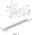
- the insulating support plate 3 is disposed on one side of the busbar group facing the battery cells 20 and is attached to the busbar group. In the embodiments, as illustrated in FIG. 3 , the insulating support plate 3 is located on a lower side of the busbar group, that is, the insulating support plate 3 is located on lower sides of the output bars and the connecting bars 10c.
- the insulating support plate 3 here provides a longitudinal i.e. upward support force for the busbar group and effectively insulates the busbar group and the battery cells 20.
- the first insulating film 4 integrally connects all the output bars and the connecting bars 10c to realize an integrated integration of the busbar group.
- the first insulating film 4 cooperates with the insulating support plate 3 to realize the integrated integration of the busbar group while ensuring the structural strength, which is conducive to maintaining a high structural strength of the CCS assembly 1 arranged using an IBB solution, which is conducive to production, assembly, and transportation of the CCS assembly 1 and effectively preventing deformation of the CCS assembly 1 during the production, assembly, and transportation.
- the first insulating film 4 is adhered to the busbar group.
- the first insulating film 4 includes a base film and an adhesive layer.
- the base film includes but is not limited to a PET film.
- the adhesive layer is configured to integrally bond the busbar group and the insulating support plate 3.
- the base film and the insulating support plate 3 wrap or clamp the busbar group and the adhesive layer to realize an integrated integration of the first insulating film 4, the busbar group, and the insulating support plate 3 of the CCS assembly 1, so that the CCS assembly 1 has high structural strength. That is, when in use, the first insulating film 4 and the insulating support plate 3 are adhered.
- the first insulating film 4 and the insulating support plate 3 may also be connected by heat riveting.
- the insulating support plate 3 is provided with heat riveting posts (not shown in the figures), and the first insulating film 4 only needs to be provided with hole structures matching the hot riveting posts.
- the first insulating film 4 is cold-pressed or hot-pressed together with the busbar group. Specifically, during a cold pressing process, the first insulating film 4 is a cold pressed film, and when in use, components of the busbar group may be directly adhered to the first insulating film 4. During a hot pressing process, the first insulating film 4 is a hot-pressed film, and when in use, after components of the busbar group are adhered to the first insulating film 4, a high-temperature holding process is required to solidify the adhesive layer.
- the insulating support plate 3 includes but is not limited to a fiberglass board or a plastic board.
- the CCS assembly 1 is applied in a cylindrical power battery module.
- a structure of the battery cell 20 is illustrated in FIG. 9 .
- a positive pole terminal 201 and a negative pole terminal 202 of the battery cell 20 are both arranged on one side toward the CCS assembly 1.
- Each connecting bar 10c includes one or more conductive units 13.
- Each conductive unit 13 includes a positive part 131 and a negative part 132 connected with each other.
- the conductive unit 13 is configured to connect two adjacent battery cells 20 in series. Specifically, the positive part 131 of the conductive unit 13 is welded to the positive pole terminal 201 of one battery cell 20, and the negative part 132 of the same conductive unit 13 is welded to the negative pole terminal 202 of the other battery cell 20.
- the plurality of connecting bars 10c are arranged along the length direction of the battery module.
- the output bars include a positive output bar 10b and a negative output bar 10a.
- the positive output bar 10b is disposed at a positive output end of the battery module
- the negative output bar 10a is disposed at a negative output end of the battery module.
- Each output bar is provided with the same number of connecting pieces as the conductive units 13 constituting one single connecting bar 10c.
- the connecting piece of the negative output bar 10a is a negative connecting piece 123a configured to connect with the negative pole terminal 202 of one battery cell 20 which is located at the negative output end of the battery module.
- the connecting piece of the positive output bar 10b is a positive connecting piece 123b configured to connect with the positive pole terminal 201 of one battery cell 20 which is located at the positive output end of the battery module.
- first welding holes 31 are defined on the insulating support plate 3, and each first welding hole 31 passes through the insulating support plate 3.
- the busbar group is exposed toward the battery cells 20 through the first welding holes 31.
- the positive parts 131 of the conductive units 13, the negative parts 132 of the conductive units 13, and the connecting pieces are exposed toward the battery cells 20 through the first welding holes 31.
- the first welding holes 31 here can not only ensure the welding of the conductive units 13 (the connecting bars 10c) and the battery cells 20, but also ensure the insulation between other parts of the connecting bars 10c and the battery cells 20, improving the safety of the CCS assembly 1 during operation.
- the first welding holes 31 here may assist in positioning during the assembly process of the CCS assembly 1 and the battery cells 20, which is beneficial to improving the assembly accuracy of the CCS assembly 1 and the battery cells 20.
- second welding holes 41 are defined on the first insulating film 4, and each second welding hole 41 passes through the first insulating film 4.
- the busbar group is exposed toward one side facing away from the battery cells 20 through the second welding holes 41.
- the positive parts 131 of the conductive units 13, the negative parts 132 of the conductive unit 13, and the connecting pieces are exposed toward the side facing away from the battery cells 20 through the second welding holes 41.
- the first welding holes 31 and the second welding holes 41 are provided correspondingly.
- a welding gun inserts into the first welding holes 31 to weld the busbar group and the battery cells 20.
- the first insulating film 4 is provided with first glue holes 43, and each first glue hole 43 passes through the first insulating film 4.
- the insulating support plate 3 is provided with second glue holes 32 corresponding to the first glue holes 43.
- the first glue hole 43 is communicated with the corresponding second glue hole 32.
- the first glue holes 43 and the second glue holes 32 are configured to inject foam glue into gaps between the battery cells 20 below the CCS assembly 1 in the battery module. After the CCS assembly 1 is assembled with the battery cells 20, the foam glue is injected from the first glue holes 43, and the foam glue enters the positions of the battery cells 20 through the second glue holes 32.
- the second glue hole 32 is communicated with the gap between two adjacent battery cells 20 corresponding to the second glue hole 32.
- Such arrangement is conducive to a smooth injection of the foam glue into the gap between the two adjacent battery cells 20, which may effectively improve the injection efficiency of the foam glue.
- part of the second glue holes 32 can discharge excess foam glue from the first glue holes 43 during a foaming process, thereby preventing the CCS assembly 1 from being excessively lifted when the foam glue is foaming toward the CCS assembly 1, thus avoiding false welding between the busbar group and the battery cells 20.
- the output bar includes an inner connection part 12 and an outer connection part 11.
- the outer connection part 11 is connected to the inner connection part 12, and they are separate parts.
- a thickness of the outer connection part 11 is greater than a thickness of the inner connection part 12.
- the insulating support plate 3 abuts against a side surface of the inner connection part 12 facing the battery cells 20 in its thickness direction.
- the insulating support plate 3 abutting the inner connection part 12 can support the thin inner connection part 12, improve the structural strength of the inner connection part 12, and effectively prevent the inner connection part 12 from being damaged during the transportation of the CCS assembly 1.
- the output bar composed of separately arranged outer connection part 11 and inner connection part 12 has simple processing technology and low production costs.
- the structural design in which the thickness of the outer connection part 11 is greater than the thickness of the inner connection part 12 may effectively improve the structural strength of the output bar, thereby improving the reliability of the connection structure between the modules when they are connected in series.
- the inner connection part 12 is integrally stamped and formed.
- the inner connection part 12 and the outer connection part 11 are welded.
- the connecting pieces are arranged on the inner connection part 12.
- the outer connection part 11 is provided in an area corresponding to the main portion 121.
- the outer connection part 11 may increase the structural strength of the main portion 121, and the insulating support plate 3 abutting the extension portions 122 may increase the structural strength of the extension portions 122.
- the structural strength of the inner connection part 12 may be improved as a whole.
- the structural arrangement of the insulating support plate 3 abutting against the extension portions 122 may balance the structural strength of each area of the inner connection part 12.
- a number of the extension portions 122 is equal to a number of the connecting pieces, and the connecting pieces are arranged in one-to-one correspondence at ends of the extension portions 122 away from the outer connection part 11.
- the CCS assembly 1 also includes second insulating films 5.
- the insulating support plate 3 is disposed between the second insulating film 5 and the output bar.
- the second insulating films 5 wrap the output bars, respectively.
- the second insulating film 5 here is made of the same material as the first insulating film 4 and is configured to wrap the corresponding output bar from bottom to top. Specifically, the second insulating film 5 is configured to wrap the main portion 121 from bottom to top to insulate the main portion 121 and the battery cells 20.
- the second insulating film 5 is adhered to one side of the main portion 121 facing the battery cells 20.
- each second insulating film 5 includes an outer wrapping portion 51 and an inner wrapping portion 52 connected with each other.
- the outer wrapping portion 51 is attached to the corresponding output bar.
- the outer wrapping portion 51 is attached to the main portion 121, and the inner wrapping portion 52 is attached to the insulating support plate 3.
- the insulating support plate 3 is provided with first positioning holes 33, and each first positioning hole 33 passes through the insulating support plate 3.
- the first insulating film 4 is provided with second positioning holes 42, and each second positioning hole 42 passes through the first insulating film 4.
- the extension portions 122 are provided with third positioning holes 125, and each third positioning hole 125 passes through the corresponding extension portion 122.
- the second insulating films 5 are provided with fourth positioning holes 521, and each fourth positioning hole 521 passes through the corresponding second insulating film 5.
- the first positioning holes 33, the second positioning holes 42, the third positioning holes 125, and the fourth positioning holes 521 here are arranged correspondingly.
- the first positioning hole 33 is coaxial with the corresponding second positioning hole 42, the corresponding third positioning hole 125, and the corresponding fourth positioning hole 521, which is configured for the positioning assembly of the first insulating film 4, the output bars, the insulating support plate 3, and the second insulating film 5, thereby improving the assembly accuracy of CCS assembly 1.
- a thickness of the insulating support plate 3 is defined as H1
- a height of a positive pole post 200 of the battery cell 20 is defined as H2
- the positive pole post 200 of the battery cell 20 passes through the insulating support plate 3 and is connected to the busbar group, where 0 ⁇ H1 ⁇ H2.
- the positive pole terminal 201 of the battery cell 20 is located on an end surface of the positive pole post 200 facing away from the negative pole terminal 202 of the battery cell 20.
- the positive pole post 200 passes through the first welding hole 31 and is connected to the busbar group.
- the structural design of 0 ⁇ H1 ⁇ H2 may prevent the insulating support plate 3 from interfering with the connection between the battery cell 20 and busbar group to prevent false welding between them.
- the CCS assembly 1 also includes a flexible printed circuit (FPC) 6 sandwiched between the first insulating film 4 and the busbar group.
- the FPC 6 is provided with collection nickel sheets 61 configured for connecting with the busbar group.
- the first insulating film 4 is provided with third welding holes 44 for exposing the collection nickel sheets 61.
- the FPC6 here collects the voltage information of the battery module by the collection nickel sheets 61 to monitor an operation condition of the battery cells.
- the structural design of the third welding holes 44 exposing the collection nickel sheets 61 facilitates the welding operation of the collection nickel sheets 61 and the corresponding busbar group during the assembly process.
- the embodiments also provide a battery module.
- the battery module includes battery cells 20 and the aforementioned CCS assembly 1.
- the battery cells 20 pass through the insulating support plate 3 and are connected to the busbar group.
- the battery module is easy to assemble and has high safety.
Landscapes
- Chemical & Material Sciences (AREA)
- Chemical Kinetics & Catalysis (AREA)
- Electrochemistry (AREA)
- General Chemical & Material Sciences (AREA)
- Inorganic Chemistry (AREA)
- Connection Of Batteries Or Terminals (AREA)
- Battery Mounting, Suspending (AREA)
Abstract
Description
- The present disclosure relates to the technical field of batteries, and in particular, to a Cells Contact System (CCS) assembly and a battery module.
- A CCS assembly of a battery module tends to be implemented using an integrated busbar for battery (IBB) solution. In the IBB solution, two layers of PET films are generally used to wrap busbars as a whole. However, the structural strength of the wrapped structure is low, which is particularly evident in a length direction of the CCS assembly. Thus, the CCS assembly is prone to deformation and bending during production and assembly, which is not conducive to production and transportation.
- The present disclosure aims to solve the following technical problems: How to improve the structural strength of the CCS assembly.
- In a first aspect, the present disclosure provides a CCS assembly applied to a battery module. The CCS assembly includes a busbar group, a first insulating film, and an insulating support plate. The busbar group includes two output bars and a plurality of connecting bars. The two output bars are correspondingly arranged at two ends of the battery module in a length direction, and the plurality of connecting bars are arranged between the two output bars. The insulating support plate is arranged parallel to the first insulating film. The first insulating film is disposed on one side of the busbar group facing away from battery cells and is attached to the busbar group. The insulating support plate is disposed on one side of the busbar group facing the battery cells and is attached to the busbar group.
- In a second aspect, the present disclosure provides a battery module. The battery module includes battery cells and the above-mentioned CCS assembly. The battery cells pass through the insulating support plate to connect with the busbar group.
- Beneficial effects: The insulating support plate of the present disclosure provides a longitudinal i.e. upward support force for the busbar group, and effectively insulates the busbar group and the battery cells; and the first insulating film integrally connects all output bars and connecting bars to realize an integrated integration of the busbar group. The first insulating film cooperates with the insulating support plate to realize the integrated integration of busbar group while ensuring the structural strength, which is conducive to maintaining high structural strength of the CCS assembly and effectively preventing deformation of the CCS assembly during production, assembly, and transportation.
-
-
FIG. 1 is a top-view structural schematic diagram of a CCS assembly provided by embodiments of the present disclosure. -
FIG. 2 is a three-dimensional structural schematic diagram of a CCS assembly provided by embodiments of the present disclosure. -
FIG. 3 is an exploded structural schematic diagram of a CCS assembly provided by embodiments of the present disclosure. -
FIG. 4 is a three-dimensional structural schematic diagram of an insulating support plate provided by embodiments of the present disclosure. -
FIG. 5 is a three-dimensional structural schematic diagram of a negative output bar provided by embodiments of the present disclosure. -
FIG. 6 is a front-view structural schematic diagram of a negative output bar provided by embodiments of the present disclosure. -
FIG. 7 is a three-dimensional structural schematic diagram of a positive output bar provided by embodiments of the present disclosure. -
FIG. 8 is a front-view structural schematic diagram of a positive output bar provided by embodiments of the present disclosure. -
FIG. 9 is a three-dimensional structural schematic diagram of a battery cell provided by embodiments of the present disclosure. -
FIG. 10 is a three-dimensional structural schematic diagram of a connecting bar provided by embodiments of the present disclosure. -
FIG. 11 is a schematic assembly diagram of a battery cell and an insulating support plate provided by embodiments of the present disclosure. - List of reference numerals: 1, CCS assembly; 10a, negative output bar; 10b, positive output bar; 10c, connecting bar; 11, outer connection part; 12, inner connection part; 121, main portion; 122, extension portion; 123a, negative connecting piece; 123b, positive connecting piece; 124, bending portion; 125, third positioning hole; 13, conductive unit; 131, positive part; 132, negative part; 20, battery cell; 200, positive pole post; 201, positive pole terminal; 202, negative pole terminal; 3, insulating support plate; 31, first welding hole; 32, second glue hole; 33, first positioning hole; 4, first insulating film; 41, second welding hole; 42, second positioning hole; 43, first glue hole; 44, third welding hole, 5, second insulating film; 51, outer wrapping portion; 52, inner wrapping portion; 521, fourth positioning hole; 6, FPC; 61, collection nickel sheet.
- Referring to
FIG. 1 to FIG. 11 , aCCS assembly 1 applied to a battery module includes a busbar group, a firstinsulating film 4, and aninsulating support plate 3. The busbar group includes two output bars and a plurality of connectingbars 10c. The two output bars are correspondingly arranged at two ends of the battery module in a length direction. The plurality of connectingbars 10c are arranged between the two output bars. Theinsulating support plate 3 is arranged parallel to the firstinsulating film 4, and the firstinsulating film 4 is disposed on one side of the busbar group facing away frombattery cells 20 of the battery module and is attached to the busbar group. Theinsulating support plate 3 is disposed on one side of the busbar group facing thebattery cells 20 and is attached to the busbar group. In the embodiments, as illustrated inFIG. 3 , theinsulating support plate 3 is located on a lower side of the busbar group, that is, theinsulating support plate 3 is located on lower sides of the output bars and the connectingbars 10c. Theinsulating support plate 3 here provides a longitudinal i.e. upward support force for the busbar group and effectively insulates the busbar group and thebattery cells 20. The firstinsulating film 4 integrally connects all the output bars and the connectingbars 10c to realize an integrated integration of the busbar group. The firstinsulating film 4 cooperates with theinsulating support plate 3 to realize the integrated integration of the busbar group while ensuring the structural strength, which is conducive to maintaining a high structural strength of theCCS assembly 1 arranged using an IBB solution, which is conducive to production, assembly, and transportation of theCCS assembly 1 and effectively preventing deformation of theCCS assembly 1 during the production, assembly, and transportation. - In the embodiments, the first
insulating film 4 is adhered to the busbar group. Further, optionally, the firstinsulating film 4 includes a base film and an adhesive layer. Optionally, the base film includes but is not limited to a PET film. When in use, the adhesive layer is configured to integrally bond the busbar group and theinsulating support plate 3. The base film and theinsulating support plate 3 wrap or clamp the busbar group and the adhesive layer to realize an integrated integration of the firstinsulating film 4, the busbar group, and theinsulating support plate 3 of theCCS assembly 1, so that theCCS assembly 1 has high structural strength. That is, when in use, the firstinsulating film 4 and theinsulating support plate 3 are adhered. - Of course, in other embodiments, the first
insulating film 4 and theinsulating support plate 3 may also be connected by heat riveting. Specifically, theinsulating support plate 3 is provided with heat riveting posts (not shown in the figures), and the firstinsulating film 4 only needs to be provided with hole structures matching the hot riveting posts. - In the embodiments, the first
insulating film 4 is cold-pressed or hot-pressed together with the busbar group. Specifically, during a cold pressing process, the firstinsulating film 4 is a cold pressed film, and when in use, components of the busbar group may be directly adhered to the firstinsulating film 4. During a hot pressing process, the firstinsulating film 4 is a hot-pressed film, and when in use, after components of the busbar group are adhered to the firstinsulating film 4, a high-temperature holding process is required to solidify the adhesive layer. - Specifically, the
insulating support plate 3 includes but is not limited to a fiberglass board or a plastic board. - In the embodiments, the
CCS assembly 1 is applied in a cylindrical power battery module. A structure of thebattery cell 20 is illustrated inFIG. 9 . Apositive pole terminal 201 and anegative pole terminal 202 of thebattery cell 20 are both arranged on one side toward theCCS assembly 1. As illustrated inFIG. 3 andFIG. 10 . Each connectingbar 10c includes one or moreconductive units 13. Eachconductive unit 13 includes apositive part 131 and anegative part 132 connected with each other. Theconductive unit 13 is configured to connect twoadjacent battery cells 20 in series. Specifically, thepositive part 131 of theconductive unit 13 is welded to thepositive pole terminal 201 of onebattery cell 20, and thenegative part 132 of the sameconductive unit 13 is welded to thenegative pole terminal 202 of theother battery cell 20. The plurality of connectingbars 10c are arranged along the length direction of the battery module. - As illustrated in
FIG. 3 , andFIG. 5 toFIG. 8 , the output bars include apositive output bar 10b and anegative output bar 10a. Thepositive output bar 10b is disposed at a positive output end of the battery module, and thenegative output bar 10a is disposed at a negative output end of the battery module. Each output bar is provided with the same number of connecting pieces as theconductive units 13 constituting onesingle connecting bar 10c. The connecting piece of thenegative output bar 10a is a negative connectingpiece 123a configured to connect with thenegative pole terminal 202 of onebattery cell 20 which is located at the negative output end of the battery module. The connecting piece of thepositive output bar 10b is a positive connectingpiece 123b configured to connect with thepositive pole terminal 201 of onebattery cell 20 which is located at the positive output end of the battery module. - In the embodiments, first welding holes 31 are defined on the insulating
support plate 3, and eachfirst welding hole 31 passes through the insulatingsupport plate 3. The busbar group is exposed toward thebattery cells 20 through the first welding holes 31. Specifically, thepositive parts 131 of theconductive units 13, thenegative parts 132 of theconductive units 13, and the connecting pieces are exposed toward thebattery cells 20 through the first welding holes 31. The first welding holes 31 here can not only ensure the welding of the conductive units 13 (the connectingbars 10c) and thebattery cells 20, but also ensure the insulation between other parts of the connectingbars 10c and thebattery cells 20, improving the safety of theCCS assembly 1 during operation. The first welding holes 31 here may assist in positioning during the assembly process of theCCS assembly 1 and thebattery cells 20, which is beneficial to improving the assembly accuracy of theCCS assembly 1 and thebattery cells 20. - Furthermore, second welding holes 41 are defined on the first insulating
film 4, and eachsecond welding hole 41 passes through the first insulatingfilm 4. The busbar group is exposed toward one side facing away from thebattery cells 20 through the second welding holes 41. Specifically, thepositive parts 131 of theconductive units 13, thenegative parts 132 of theconductive unit 13, and the connecting pieces are exposed toward the side facing away from thebattery cells 20 through the second welding holes 41. - In the embodiments, the first welding holes 31 and the second welding holes 41 are provided correspondingly. When in use, a welding gun inserts into the first welding holes 31 to weld the busbar group and the
battery cells 20. - In the embodiments, the first insulating
film 4 is provided with first glue holes 43, and eachfirst glue hole 43 passes through the first insulatingfilm 4. The insulatingsupport plate 3 is provided with second glue holes 32 corresponding to the first glue holes 43. Thefirst glue hole 43 is communicated with the correspondingsecond glue hole 32. The first glue holes 43 and the second glue holes 32 are configured to inject foam glue into gaps between thebattery cells 20 below theCCS assembly 1 in the battery module. After theCCS assembly 1 is assembled with thebattery cells 20, the foam glue is injected from the first glue holes 43, and the foam glue enters the positions of thebattery cells 20 through the second glue holes 32. - Furthermore, the
second glue hole 32 is communicated with the gap between twoadjacent battery cells 20 corresponding to thesecond glue hole 32. Such arrangement is conducive to a smooth injection of the foam glue into the gap between the twoadjacent battery cells 20, which may effectively improve the injection efficiency of the foam glue. Moreover, part of the second glue holes 32 can discharge excess foam glue from the first glue holes 43 during a foaming process, thereby preventing theCCS assembly 1 from being excessively lifted when the foam glue is foaming toward theCCS assembly 1, thus avoiding false welding between the busbar group and thebattery cells 20. - In the embodiments, as illustrated in
FIG. 3 andFIG. 5 toFIG. 8 , the output bar includes aninner connection part 12 and anouter connection part 11. Theouter connection part 11 is connected to theinner connection part 12, and they are separate parts. A thickness of theouter connection part 11 is greater than a thickness of theinner connection part 12. The insulatingsupport plate 3 abuts against a side surface of theinner connection part 12 facing thebattery cells 20 in its thickness direction. The insulatingsupport plate 3 abutting theinner connection part 12 can support the thininner connection part 12, improve the structural strength of theinner connection part 12, and effectively prevent theinner connection part 12 from being damaged during the transportation of theCCS assembly 1. Moreover, the output bar composed of separately arrangedouter connection part 11 andinner connection part 12 has simple processing technology and low production costs. Moreover, the structural design in which the thickness of theouter connection part 11 is greater than the thickness of theinner connection part 12 may effectively improve the structural strength of the output bar, thereby improving the reliability of the connection structure between the modules when they are connected in series. In the embodiments, theinner connection part 12 is integrally stamped and formed. Theinner connection part 12 and theouter connection part 11 are welded. In the embodiments, the connecting pieces are arranged on theinner connection part 12. - Furthermore, the
inner connection part 12 includes amain portion 121 connected to theouter connection part 11. One ormore extension portions 122 are provided on one side of themain portion 121 away from theouter connection part 11. Theextension portion 122 is configured to connect with thepositive pole terminal 201 or thenegative pole terminal 202 of thebattery cell 20. The insulatingsupport plate 3 abuts against theextension portion 122. An extending direction of theextension portion 122 here is parallel to an extending direction of themain portion 121, and theextension portions 122 are connected to themain portion 121 by a bendingportion 124. Furthermore, themain portion 121, the bendingportion 124, and the one ormore extension portions 122 are integrally formed. In the embodiments, theouter connection part 11 is provided in an area corresponding to themain portion 121. Theouter connection part 11 may increase the structural strength of themain portion 121, and the insulatingsupport plate 3 abutting theextension portions 122 may increase the structural strength of theextension portions 122. Thus, the structural strength of theinner connection part 12 may be improved as a whole. The structural arrangement of the insulatingsupport plate 3 abutting against theextension portions 122 may balance the structural strength of each area of theinner connection part 12. In the embodiments, a number of theextension portions 122 is equal to a number of the connecting pieces, and the connecting pieces are arranged in one-to-one correspondence at ends of theextension portions 122 away from theouter connection part 11. - As illustrated in
FIG. 3 , theCCS assembly 1 also includes second insulatingfilms 5. The insulatingsupport plate 3 is disposed between the secondinsulating film 5 and the output bar. The secondinsulating films 5 wrap the output bars, respectively. The secondinsulating film 5 here is made of the same material as the first insulatingfilm 4 and is configured to wrap the corresponding output bar from bottom to top. Specifically, the secondinsulating film 5 is configured to wrap themain portion 121 from bottom to top to insulate themain portion 121 and thebattery cells 20. - In the embodiments, the second
insulating film 5 is adhered to one side of themain portion 121 facing thebattery cells 20. - In the embodiments, the second insulating
films 5 are provided at ends of the insulatingsupport plate 3 in its length direction. The length direction of the insulatingsupport plate 3 is parallel to the length direction of the battery module. The secondinsulating films 5 here cooperate with the insulatingsupport plate 3 to insulate the busbar group and thebattery cells 20. Specifically, as illustrated inFIG. 3 , each second insulatingfilm 5 includes anouter wrapping portion 51 and aninner wrapping portion 52 connected with each other. Theouter wrapping portion 51 is attached to the corresponding output bar. Specifically, theouter wrapping portion 51 is attached to themain portion 121, and theinner wrapping portion 52 is attached to the insulatingsupport plate 3. - In other embodiments, the two second insulating
films 5 at ends of the insulatingsupport plate 3 may be integrally formed, that is, the second insulatingfilms 5 are designed as a whole body and spread on a side surface of the insulatingsupport plate 3 facing thebattery cells 20, and an end portion of the secondinsulating film 5 extends to the correspondingmain portion 121. It should be noted that in the embodiments, the second insulatingfilms 5 are provided with avoidance gaps corresponding to the first welding holes 31 to ensure that the busbar group can be welded to thebattery cells 20. - In the embodiments, the insulating
support plate 3 is provided with first positioning holes 33, and eachfirst positioning hole 33 passes through the insulatingsupport plate 3. The firstinsulating film 4 is provided with second positioning holes 42, and eachsecond positioning hole 42 passes through the first insulatingfilm 4. Theextension portions 122 are provided with third positioning holes 125, and eachthird positioning hole 125 passes through thecorresponding extension portion 122. The secondinsulating films 5 are provided with fourth positioning holes 521, and eachfourth positioning hole 521 passes through the corresponding second insulatingfilm 5. The first positioning holes 33, the second positioning holes 42, the third positioning holes 125, and the fourth positioning holes 521 here are arranged correspondingly. When in use, after the first insulatingfilm 4, the output bars, the insulatingsupport plate 3, and the secondinsulating film 5 are assembled, thefirst positioning hole 33 is coaxial with the correspondingsecond positioning hole 42, the correspondingthird positioning hole 125, and the correspondingfourth positioning hole 521, which is configured for the positioning assembly of the first insulatingfilm 4, the output bars, the insulatingsupport plate 3, and the secondinsulating film 5, thereby improving the assembly accuracy ofCCS assembly 1. - In the embodiments, as illustrated in
FIG. 11 , a thickness of the insulatingsupport plate 3 is defined as H1, a height of apositive pole post 200 of thebattery cell 20 is defined as H2, and thepositive pole post 200 of thebattery cell 20 passes through the insulatingsupport plate 3 and is connected to the busbar group, where 0 < H1 ≤ H2. Thepositive pole terminal 201 of thebattery cell 20 is located on an end surface of thepositive pole post 200 facing away from thenegative pole terminal 202 of thebattery cell 20. Thepositive pole post 200 passes through thefirst welding hole 31 and is connected to the busbar group. The structural design of 0 < H1 ≤ H2 may prevent the insulatingsupport plate 3 from interfering with the connection between thebattery cell 20 and busbar group to prevent false welding between them. - As illustrated in
FIG. 3 , theCCS assembly 1 also includes a flexible printed circuit (FPC) 6 sandwiched between the first insulatingfilm 4 and the busbar group. TheFPC 6 is provided withcollection nickel sheets 61 configured for connecting with the busbar group. The firstinsulating film 4 is provided with third welding holes 44 for exposing thecollection nickel sheets 61. The FPC6 here collects the voltage information of the battery module by thecollection nickel sheets 61 to monitor an operation condition of the battery cells. The structural design of the third welding holes 44 exposing thecollection nickel sheets 61 facilitates the welding operation of thecollection nickel sheets 61 and the corresponding busbar group during the assembly process. - The embodiments also provide a battery module. The battery module includes
battery cells 20 and theaforementioned CCS assembly 1. Thebattery cells 20 pass through the insulatingsupport plate 3 and are connected to the busbar group. The battery module is easy to assemble and has high safety.
Claims (15)
- A cells contact system (CCS) assembly (1), applied in a battery module and characterized by comprising:a busbar group, comprising two output bars (10a, 10b) and a plurality of connecting bars (10c), wherein the two output bars (10a, 10b) are correspondingly arranged at two ends of the battery module in a length direction, and the plurality of connecting bars (10c) are arranged between the two output bars (10a, 10b);a first insulating film (4); andan insulating support plate (3), arranged parallel to the first insulating film (4),wherein the first insulating film (4) is disposed on one side of the busbar group facing away from battery cells (20) of the battery module and is attached to the busbar group, and the insulating support plate (3) is disposed on one side of the busbar group facing the battery cells (20) and is attached to the busbar group.
- The CCS assembly according to claim 1, characterized in that the first insulating film (4) is adhered to the busbar group.
- The CCS assembly according to claim 1 or claim 2, characterized in that the insulating support plate (3) is provided with first welding holes (31) each passing through the insulating support plate (3), and the busbar group is exposed toward the battery cells (20) through the first welding holes (31).
- The CCS assembly according to claim 1 or claim 2, characterized in that the first insulating film (4) is provided with second welding holes (41) each passing through the first insulating film (4), and the busbar group is exposed toward one side facing away from the battery cells (20) through the second welding holes (41).
- The CCS assembly according to claim 1 or claim 2, characterized in that the first insulating film (4) is provided with first glue holes (43) each passing through the first insulating film (4), the insulating support plate (3) is provided with second glue holes (32) corresponding to the first glue holes (43), and each of the first glue holes (43) is communicated with a corresponding one of the second glue holes (32); and
each of the second glue holes (32) is communicated with a gap between two corresponding and adjacent ones of the battery cells (20). - The CCS assembly according to claim 1, characterized in that each of the output bars (10a, 10b) comprises:an inner connection part (12); andan outer connection part (11), connected to the inner connection part (12),wherein the outer connection part (11) and the inner connection part (12) are separate parts;a thickness of the outer connection part (11) is greater than a thickness of the inner connection part (12); andthe insulating support plate (3) abuts against a side surface of the inner connection part (12) facing the battery cells (20) in its thickness direction;wherein the inner connection part (12) comprises:a main portion (121), connected to the outer connection part (11); andat least one extension portion (122), provided on one side of the main portion (121) facing away from the outer connection part (11), and configured to connect with a positive pole terminal (201) or a negative pole terminal (202) of one of the battery cells (20),wherein the insulating support plate (3) abuts against the extension portion (122).
- The CCS assembly according to any one of claims 1, 2, 5, and 6, characterized by further comprising two second insulating films (5), wherein the insulating support plate (3) is disposed between the second insulating films (5) and the output bars (10a, 10b), and one of the second insulating films (5) wraps one of the output bars (10a, 10b) that is correspondingly arranged.
- The CCS assembly according to claim 7, characterized in that the second insulating films (5) are provided at ends of the insulating support plate (3) in its length direction; and
a length direction of the insulating support plate (3) is parallel to the length direction of the battery module. - The CCS assembly according to claim 7, characterized in that each of the second insulating films (5) comprises an outer wrapping portion (51) and an inner wrapping portion (52) connected with each other, the outer wrapping portion (51) is attached to a corresponding one of the output bars (10a, 10b), and the inner wrapping portion (52) is attached to the insulating support plate (3).
- The CCS assembly according to any one of claims 1, 2, 5, and 6, characterized in that the insulating support plate (3) is a fiberglass board or a plastic board.
- The CCS assembly according to claim 1, characterized in that the first insulating film (4) is cold-pressed or hot-pressed together with the busbar group.
- The CCS assembly according to claim 1, characterized in that a thickness of the insulating support plate (3) is defined as H1, a height of a positive pole post (200) of each of the battery cells (20) is defined as H2;the positive pole post (200) passes through the insulating support plate (3) and is connected to the busbar group; andwhere 0 < H1 ≤ H2.
- The CCS assembly according to claim 1, characterized by further comprising a flexible printed circuit (FPC) (6) sandwiched between the first insulating film (4) and the busbar group,wherein the FPC (6) is provided with collection nickel sheets (61) configured for connecting with the busbar group; andthe first insulating film (4) is provided with third welding holes (44) for exposing the collection nickel sheets (61).
- The CCS assembly according to claim 1, characterized in that the first insulating film (4) is adhered with the insulating support plate (3).
- A battery module, characterized by comprising battery cells (20) and the CCS assembly (1) according to any one of claims 1-14, wherein the battery cells (20) pass through the insulating support plate (3) to connect with the busbar group.
Applications Claiming Priority (2)
| Application Number | Priority Date | Filing Date | Title |
|---|---|---|---|
| CN202322472913.0U CN221126191U (en) | 2023-09-12 | 2023-09-12 | CCS assembly and battery module |
| PCT/CN2024/088259 WO2025055327A1 (en) | 2023-09-12 | 2024-04-17 | Ccs assembly and battery module |
Publications (2)
| Publication Number | Publication Date |
|---|---|
| EP4525154A2 true EP4525154A2 (en) | 2025-03-19 |
| EP4525154A3 EP4525154A3 (en) | 2025-05-07 |
Family
ID=92762074
Family Applications (1)
| Application Number | Title | Priority Date | Filing Date |
|---|---|---|---|
| EP24199633.9A Pending EP4525154A3 (en) | 2023-09-12 | 2024-09-11 | Ccs assembly and battery module |
Country Status (2)
| Country | Link |
|---|---|
| US (1) | US20250087862A1 (en) |
| EP (1) | EP4525154A3 (en) |
Family Cites Families (3)
| Publication number | Priority date | Publication date | Assignee | Title |
|---|---|---|---|---|
| CN109103405A (en) * | 2018-08-19 | 2018-12-28 | 江西赣锋电池科技有限公司 | A kind of battery pack busbar, preparation method and battery pack |
| EP3872891A1 (en) * | 2020-02-27 | 2021-09-01 | Mersen France Angers SAS | Laminated busbar for energy storage device |
| EP4256646A4 (en) * | 2020-12-04 | 2025-05-28 | Telo Trucks Inc. | Manufacturing a battery pack using a welding jig |
-
2024
- 2024-09-11 US US18/882,729 patent/US20250087862A1/en active Pending
- 2024-09-11 EP EP24199633.9A patent/EP4525154A3/en active Pending
Also Published As
| Publication number | Publication date |
|---|---|
| US20250087862A1 (en) | 2025-03-13 |
| EP4525154A3 (en) | 2025-05-07 |
Similar Documents
| Publication | Publication Date | Title |
|---|---|---|
| JP5522748B2 (en) | Battery module | |
| US20230112961A1 (en) | Sampling circuit board for battery module and battery module | |
| JP5544931B2 (en) | Laminated cell battery structure | |
| EP3886205B1 (en) | Battery module | |
| JP2005285625A (en) | Battery frame and battery pack | |
| CN210006811U (en) | Battery packs for cells, battery packs and vehicles | |
| EP2800163A1 (en) | Battery coupling method and battery coupling device | |
| CN115295967A (en) | Integrated collection busbar for battery module | |
| CN113161672A (en) | Battery module and battery pack with same | |
| CN111916643A (en) | Cell assembly and battery pack | |
| WO2024103581A1 (en) | Battery cell adapter, battery cell stack, and module-free battery pack | |
| CN108352469A (en) | group battery | |
| JP5481970B2 (en) | Battery module and manufacturing method thereof | |
| CN117335100A (en) | CCS components and battery modules | |
| EP4525154A2 (en) | Ccs assembly and battery module | |
| CN221126191U (en) | CCS assembly and battery module | |
| CN113054284A (en) | Battery module, corresponding method and battery pack | |
| CN216958280U (en) | Battery module structure | |
| CN212695239U (en) | Lithium battery module structure | |
| CN220856839U (en) | CCS assembly and battery module | |
| CN117956686A (en) | Circuit board, manufacturing method thereof and battery assembly | |
| CN223109049U (en) | Battery module frame components, battery modules and battery packs | |
| US20250087843A1 (en) | Ccs assembly and battery module | |
| CN220066020U (en) | Battery pack | |
| CN220710584U (en) | Soft packet of lithium cell sampling connection integrated configuration |
Legal Events
| Date | Code | Title | Description |
|---|---|---|---|
| PUAI | Public reference made under article 153(3) epc to a published international application that has entered the european phase |
Free format text: ORIGINAL CODE: 0009012 |
|
| STAA | Information on the status of an ep patent application or granted ep patent |
Free format text: STATUS: REQUEST FOR EXAMINATION WAS MADE |
|
| 17P | Request for examination filed |
Effective date: 20240911 |
|
| AK | Designated contracting states |
Kind code of ref document: A2 Designated state(s): AL AT BE BG CH CY CZ DE DK EE ES FI FR GB GR HR HU IE IS IT LI LT LU LV MC ME MK MT NL NO PL PT RO RS SE SI SK SM TR |
|
| PUAL | Search report despatched |
Free format text: ORIGINAL CODE: 0009013 |
|
| AK | Designated contracting states |
Kind code of ref document: A3 Designated state(s): AL AT BE BG CH CY CZ DE DK EE ES FI FR GB GR HR HU IE IS IT LI LT LU LV MC ME MK MT NL NO PL PT RO RS SE SI SK SM TR |
|
| RIC1 | Information provided on ipc code assigned before grant |
Ipc: H01M 50/516 20210101ALI20250401BHEP Ipc: H01M 50/522 20210101ALI20250401BHEP Ipc: H01M 50/51 20210101ALI20250401BHEP Ipc: H01M 50/502 20210101ALI20250401BHEP Ipc: H01M 50/526 20210101ALI20250401BHEP Ipc: H01M 50/524 20210101ALI20250401BHEP Ipc: H01M 50/519 20210101ALI20250401BHEP Ipc: H01M 50/507 20210101ALI20250401BHEP Ipc: H01M 50/284 20210101ALI20250401BHEP Ipc: H01M 50/213 20210101AFI20250401BHEP |