EP4525148A1 - A prismatic battery cell comprising a venting membrane - Google Patents
A prismatic battery cell comprising a venting membrane Download PDFInfo
- Publication number
- EP4525148A1 EP4525148A1 EP23306531.7A EP23306531A EP4525148A1 EP 4525148 A1 EP4525148 A1 EP 4525148A1 EP 23306531 A EP23306531 A EP 23306531A EP 4525148 A1 EP4525148 A1 EP 4525148A1
- Authority
- EP
- European Patent Office
- Prior art keywords
- venting
- cover plate
- weakness line
- membrane
- venting membrane
- Prior art date
- Legal status (The legal status is an assumption and is not a legal conclusion. Google has not performed a legal analysis and makes no representation as to the accuracy of the status listed.)
- Pending
Links
Images

Classifications
-
- H—ELECTRICITY
- H01—ELECTRIC ELEMENTS
- H01M—PROCESSES OR MEANS, e.g. BATTERIES, FOR THE DIRECT CONVERSION OF CHEMICAL ENERGY INTO ELECTRICAL ENERGY
- H01M50/00—Constructional details or processes of manufacture of the non-active parts of electrochemical cells other than fuel cells, e.g. hybrid cells
- H01M50/30—Arrangements for facilitating escape of gases
- H01M50/342—Non-re-sealable arrangements
- H01M50/3425—Non-re-sealable arrangements in the form of rupturable membranes or weakened parts, e.g. pierced with the aid of a sharp member
-
- H—ELECTRICITY
- H01—ELECTRIC ELEMENTS
- H01M—PROCESSES OR MEANS, e.g. BATTERIES, FOR THE DIRECT CONVERSION OF CHEMICAL ENERGY INTO ELECTRICAL ENERGY
- H01M50/00—Constructional details or processes of manufacture of the non-active parts of electrochemical cells other than fuel cells, e.g. hybrid cells
- H01M50/10—Primary casings; Jackets or wrappings
- H01M50/147—Lids or covers
-
- H—ELECTRICITY
- H01—ELECTRIC ELEMENTS
- H01M—PROCESSES OR MEANS, e.g. BATTERIES, FOR THE DIRECT CONVERSION OF CHEMICAL ENERGY INTO ELECTRICAL ENERGY
- H01M50/00—Constructional details or processes of manufacture of the non-active parts of electrochemical cells other than fuel cells, e.g. hybrid cells
- H01M50/10—Primary casings; Jackets or wrappings
- H01M50/147—Lids or covers
- H01M50/148—Lids or covers characterised by their shape
- H01M50/15—Lids or covers characterised by their shape for prismatic or rectangular cells
-
- H—ELECTRICITY
- H01—ELECTRIC ELEMENTS
- H01M—PROCESSES OR MEANS, e.g. BATTERIES, FOR THE DIRECT CONVERSION OF CHEMICAL ENERGY INTO ELECTRICAL ENERGY
- H01M50/00—Constructional details or processes of manufacture of the non-active parts of electrochemical cells other than fuel cells, e.g. hybrid cells
- H01M50/10—Primary casings; Jackets or wrappings
- H01M50/102—Primary casings; Jackets or wrappings characterised by their shape or physical structure
- H01M50/103—Primary casings; Jackets or wrappings characterised by their shape or physical structure prismatic or rectangular
-
- Y—GENERAL TAGGING OF NEW TECHNOLOGICAL DEVELOPMENTS; GENERAL TAGGING OF CROSS-SECTIONAL TECHNOLOGIES SPANNING OVER SEVERAL SECTIONS OF THE IPC; TECHNICAL SUBJECTS COVERED BY FORMER USPC CROSS-REFERENCE ART COLLECTIONS [XRACs] AND DIGESTS
- Y02—TECHNOLOGIES OR APPLICATIONS FOR MITIGATION OR ADAPTATION AGAINST CLIMATE CHANGE
- Y02E—REDUCTION OF GREENHOUSE GAS [GHG] EMISSIONS, RELATED TO ENERGY GENERATION, TRANSMISSION OR DISTRIBUTION
- Y02E60/00—Enabling technologies; Technologies with a potential or indirect contribution to GHG emissions mitigation
- Y02E60/10—Energy storage using batteries
Definitions
- the invention generally relates to the technical field of energy storage devices, and in particular to an electrochemical battery cell comprising a venting membrane.
- Electrochemical battery cells are used in electric or hybrid vehicles, i.e., those which move at least partially by electrical energy, for example.
- Motor vehicles with electric or hybrid traction or propulsion comprise one or more battery modules connected to a power network for powering an electric (traction or propulsion) motor.
- the battery modules are grouped together in a casing and then form a battery pack, this casing generally containing a mounting interface and connection terminals.
- Each battery module comprises at least one electrochemical battery cell generating current by chemical reaction, for example, of the lithium-ion (or Li-ion) type, or of the Ni-MH, or Ni-Cd or lead acid type.
- An electrochemical battery cell comprises, in particular, an electrode stack(s) comprising multiple positive electrodes, multiple separator layers, and multiple anode electrodes.
- the cathodes form (+) electrical pole of the stack combining all the cathodes electrically
- the anodes form (-) electrical pole of the stack combining all the anodes electrically
- all the cathodes and anodes in the stack are electrically separated by the separator layers.
- the combined cathodes connect to the positive terminal of the electrochemical battery cell, and the combined anodes connect to the negative terminal of the electrochemical battery cell.
- the electrode stack(s) is housed in a metal housing.
- the housing is generally made of aluminum. Once the assembly of electrode stack(s) is integrated into the housing, a top cover comprising a plate is laser-welded to the housing to produce the structural connection and the sealing of the electrochemical battery cell.
- the top cover comprises a positive terminal, a negative terminal and (a) venting hole(s), positioned nearby the two terminals, closed by a venting membrane.
- the venting membrane comprises a peripheral border attached to the plate.
- the venting membrane is leak-tightly sealed with an internal edge of the plate delimiting the venting hole.
- the venting membrane is welded to the internal edge around the entire perimeter of the venting hole.
- venting hole and the venting membrane form a venting window having an elongated shape.
- the venting window has an oblong shape including a first end and an opposite second end having both a convex curvature.
- the shape of the venting window comprises two parallel identical straight lines connecting tangentially two identical mirrored arcs. The arcs have the shape of half circles and are opposed to each other. The two parallel identical straight lines are opposed to each other as well.
- a weakness line or pre-cracked notch extends longitudinally along the venting membrane.
- the membrane has a safety function.
- the stack of electrodes can release gases due to chemical reactions leading to an increase of the pressure inside the electrochemical battery cell. If the internal gas pressure of the electrochemical battery cell reaches a critical pressure abnormally, the venting membrane gets the pressure and deforms in such a way as to increase the stress higher at the pre-cracked notch. If the stress passes its strength limit at any point of the notch, the point triggers the membrane breakage, and the internal gas gets released leading to securing the electrochemical battery cell and avoiding an explosion.
- the pre-cracked notch is rather long.
- the breakage can occur at any point of the pre-cracked notch.
- the invention aims to remedy all or some of the drawbacks of the prior art by proposing an electrochemical battery cell improving the safety function of the opening of the venting membrane.
- the invention proposes a cover plate of a top cover of an electrochemical battery cell.
- the electrochemical battery cell comprises a positive terminal and a negative terminal.
- the cover plate comprises a venting hole with an internal edge delimiting the venting hole having an oblong shape extending along a longitudinal reference axis and closed by a venting membrane comprising a weakness line extending longitudinally along the center of the venting membrane.
- the cover plate comprises a stress means configured to concentrate tensile stress in a desired breaking point of the weakness line to initiate a break from the breaking point while an internal gas pressure inside the can increase up to a threshold of pressure deforming the venting membrane.
- the invention thus provides an electrochemical battery cell, improving the safety function of the opening of the venting membrane in a more precise way.
- a target point on the weakness line of the membrane is provided to initiate the breakage of the venting membrane at a desired point. Therefore, the safety function of the opening of the venting membrane is more precisely reproducible at the targeted/designed pressure with a minor variance from cell to cell.
- the internal edge comprises two sectors of arcuate profile, preferably of circular profile, facing each other.
- the weakness line of the venting membrane has a middle positioned at an equal distance from the two sectors of arcuate profile.
- the desired breaking point of the weakness line is positioned in the middle of the weakness line.
- the breakage of the membrane may start at the center with a higher probability.
- the two sectors of arcuate profile are symmetrical about an axis of symmetry.
- the axis of symmetry is preferably transverse to the longitudinal reference axis.
- This configuration provides a tensile stress distribution along the weakness line in a symmetric shape, which is higher than the average stress at the center and lower at the locations away from the center.
- the stress means comprises a shrinkage area formed in the venting hole.
- the two sectors of arcuate profile are separated by two concave portions facing each other so as to delimit the shrinkage area.
- the two concave portions have preferably an arcuate profile, preferably also a circular profile.
- This shape enables the concentration of the tensile stress between the two arcuate profiles.
- the two concave portions are symmetrical about an axis of symmetry.
- the axis of symmetry is preferably coaxial to the longitudinal reference axis.
- the curvature radius ratio between the two sectors of arcuate profile of the concave portions and the two sectors of circular profile is greater than 15, preferably greater than 20, and/or less than 30, preferably less than 25.
- the venting membrane has the same shape as that of the venting hole and comprises a shrinkage area.
- the venting membrane is bordered by a peripheral border having a shape so that a shape of the venting membrane corresponding to an homothety of the shape of the venting hole.
- the stress means comprise a plurality of recesses, preferably an even number of recesses, for example two, formed in the venting membrane.
- the recesses are positioned on either side of the weakness line.
- the recesses help to start the breakage at the desired breaking point with a higher probability.
- the probability that the breakage start at the desired breaking point is very high.
- each recess has a circular section.
- This shape provides is optimal for starting the breakage of the weakness line.
- the recesses are positioned closer to the weakness line than the venting membrane's peripheral border.
- This position is optimal for providing residual tensile stress around the center of the weakness line with high reproducibility for all the electrochemical battery cells.
- the recesses are aligned with the middle of the weakness line and/or are symmetrical about the weakness line.
- the breakage may start at the center with a higher probability.
- the invention also relates to an electrochemical battery cell comprising a cover plate as defined previously.
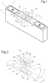
- the invention relates to an electrochemical battery cell 1, as shown in Figure 1 , which can be used, for example, in an electric or hybrid vehicle, i.e., one which moves at least partially by electrical energy, for example.
- An electrochemical battery cell 1 comprises, in particular, an electrode stack(s) comprising multiple positive electrodes, multiple separator layers, and multiple anode electrodes.
- the cathodes form the (+) electrical pole of the stack combining all the cathodes electrically
- the anodes form the (-) electrical pole of the electrode stack combining all the anodes electrically
- all the cathodes and anodes in the stack are electrically separated by the separator layers.
- the combined cathodes connect to the positive terminal 6 of the electrochemical battery cell 1
- the combined anodes connect to the negative terminal 7 of the electrochemical battery cell 1.
- module In order to mechanically assemble the electrically connected electrochemical battery cells 1 , it is known to align them on a flat support or a rail and keep them at the two ends compressed by fixed parallel plates, such an assembly being designated by the term "module”.
- a plurality of modules is grouped together in a casing and then form a battery pack, this casing generally contains a mounting interface and connection terminals.
- Each electrode stack is accommodated in a metallic can 2 which is generally made of aluminum and is hollow.
- a top cover 3 comprising a metallic plate 5 , is laser-welded to the can 2 , for closing an upper opening 4 of the can 2.
- the electrochemical battery cell 1 has a parallelepipedal shape of a rectangular cross-section.
- the top cover 3 comprises the positive terminal 6 and a negative terminal 7.
- a venting hole 8 is formed in the plate 5 and positioned between the two terminals 6, 7.
- the venting hole 8 has an oblong shape extending along a longitudinal reference axis X.
- the venting hole 8 is delimited by an internal edge 9 of the plate 5 and is closed by a venting membrane 10.
- venting hole 8 could be positioned differently on the plate 5 or being positioned on another wall of the can 2.
- the venting membrane 10 comprises a peripheral border 11 attached to the plate 5.
- the venting membrane 10 is leak-tightly sealed with the internal edge 9.
- the venting membrane 10 is welded to the internal edge 9 around the entire perimeter of the venting hole 8.
- the internal edge 9 of the plate 5 comprises a lower shoulder 29 and an upper shoulder 30 positioned above the lower shoulder 29.
- the venting membrane 10 is sealed on the lower shoulder 29.
- the top cover 3 comprises a vent cover 31 positioned in front of and above the venting membrane 10.
- the vent cover 31 is fixed on the upper shoulder 30 of the internal edge 9 of the plate 5.
- the vent cover 31 and the venting membrane 10 are spaced out.
- the vent cover 31 can have the same shape as the venting membrane 10 and the venting hole 8 or have a different shape, as an oblong or elliptical shape for instance.
- venting hole 8 and the venting membrane 10 form a venting window having an elongated shape.
- a weakness line 16 or pre-cracked notch extends longitudinally along the venting membrane 10 as shown in figures 1 to 3 .
- the weakness line 16 extends along a longitudinal reference axis X.
- the venting membrane 10 has a safety function.
- the stack of electrodes can release gases due to chemical reactions leading to increase the pressure inside the electrochemical battery cell 1. If the internal pressure of the electrochemical battery cell 1 reaches a critical pressure, the venting membrane 10 gets the pressure and deforms in such a way as to increase the stress higher at the weakness line 16. If the stress passes its strength limit at any point of the weakness line 1 6 , the point triggers the venting membrane 10 breakage, and the internal pressure gets released leading to secure the electrochemical battery cell 1 and avoiding an explosion.
- the internal edge 9 of the plate 5 comprises two sectors of arcuate profile 12 , 13 , preferably of circular profile, facing each other.
- the two sectors of arcuate profile 12 , 13 have a convex shape and are symmetrical about an axis of symmetry Y.
- the axis of symmetry Y is preferably transverse to the longitudinal reference axis X.
- the venting membrane 10 has the same shape as the venting hole 8 in the example of figures 1 to 4 .
- the venting membrane 10 comprises a first curved end 20 attached to a first arcuate profile 12 of the internal edge 9 and a second curved end 21 attached to a second arcuate profile 13 of the internal edge 9.
- the venting membrane 10 can have a different shape than that of the venting hole 8 as an oblong and elongated shape.
- the first and second curved ends 20 , 21 of the venting membrane 10 can comprise both a convex curvature.
- the venting membrane 10 comprises two parallel identical straight lines connecting tangentially the two identical curved ends 20 , 21 .
- the first and second curved ends 20 , 21 have a shape of half circles and are opposed to each other.
- the two parallel identical straight lines are opposed to each other as well.
- the weakness line 16 of the venting membrane 10 comprises a middle 17 positioned at equal distance from the two sectors of arcuate circular profile 12 , 13 .
- the top cover 3 comprises a stress means 14 , 27 , 28 configured to concentrate a tensile stress in the middle 17 of the weakness line 16 to break it while an internal gas pressure inside the can 2 increases up to a threshold of pressure (or critical pressure) deforming the venting membrane 10.
- the stress means 14 , 27 , 28 provides a target point on the weakness line 16 of the venting membrane 10 to initiate the breakage of the venting membrane 10 at a desired breaking point 32 of the weakness line 16. Therefore, the safety function of the breaking of the venting membrane 10 is more precisely reproducible at the targeted/designed pressure (threshold of pressure) with a minor variance from electrochemical battery cell 1 to electrochemical battery cell 1.
- the desired breaking point 32 of the weakness line 16 is positioned in the middle 17 of the weakness line 16.
- the stress means 14 , 27 , 28 is provided by a particular shape of the venting hole 8.
- the stress means 14 , 27 , 28 comprises a shrinkage area 14 formed in the venting hole 8.
- the internal edge 9 of the plate 5 comprises two concave portions 18 , 19 facing each other so as to delimit the shrinkage area 14.
- the two sectors of arcuate profile 12 , 13 are separated by the two concave portions 18 , 19 .
- the two concave portions 18 , 19 have preferably an arcuate profile.
- the two concave portions 18 , 19 have preferably a circular profile.
- the two concave portions 18 , 19 can have an elliptical profile.
- the two concave portions 18 , 19 have a curvature radius smaller than the two sectors of arcuate profile 12 , 13 .
- the two concave portions 18 , 19 of the internal edge 9 of the plate 5 have each a tangent point 24 , 25 , as shown in figure 3 , that is the point of the two concave portions 18 , 19 which is positioned closest to the weakness line 16 .
- the tangent points 24 , 25 are aligned with the middle 17 of the weakness line 16 .
- the curvature radius ratio between the two concave portions 18 , 19 and the two sectors of circular profile 12 , 13 of the internal edge 9 of the plate 5 is greater than 15, preferably greater than 20, and/or less than 30, preferably less than 25 for a prismatic battery cell design which has, in particular, 34 mm thickness and 200 mm length, but not limited to.
- the curvature radius of the two sectors of circular profile 12 , 13 of the internal edge 9 of the plate 5 is greater than 8 mm, preferably greater than 10 mm, and/or less than 15 mm, preferably less than 13 mm for a prismatic battery cell design which has, in particular, 34 mm thickness and 200 mm length, but not limited to.
- the radius of the two concave portions 18 , 19 of the internal edge 9 of the plate 5 is greater than 220 mm, preferably greater than 230 mm, and/or less than 260 mm, preferably less than 250 mm for a prismatic battery cell design which has, in particular, 34 mm thickness and 200 mm length, but not limited to.
- the venting membrane 10 has a same shape than that of the venting hole 8 and comprises also a shrinkage area 15.
- the venting membrane 10 is bordered by a peripheral border 11 having a shape so that the venting membrane 10 corresponding to an homothety of the shape of the venting hole 8.
- the peripheral border 11 of the venting membrane 10 comprises a third curved end 22 and a fourth curved end 23 having both a concave curvature.
- the third curved end 22 extends along the first concave portion 18 of the internal edge 9 of the plate 5 and the second curved end 23 extends along the second concave portion 19 of the internal edge 9 of the plate 5.
- the third and fourth curved ends 22 , 23 are opposed and separated by the weakness line 16.
- the third and fourth curved ends 22 , 23 have a curvature radius smaller than the curvature radius of the first and second curved ends 20 , 21 .
- the curved ends 20 , 21 , 22 , 23 of the venting membrane 10 have a circular shape.
- venting membrane 10 and the venting hole 8 form a venting window having approximately a bean shape.
- the venting membrane 10 has a different shape than that of the venting hole 8, as said previously, and does not comprise a shrinkage area 15.
- the pressure inside the electrochemical battery cell 1 increases while the stack of electrodes releases gases due to chemical reactions.
- the venting membrane 10 deforms in such a way as to increase the stress higher at the middle 17 of the weakness line 16 due to the two concave portions 18 , 19 that are protruding towards the middle 17 of the weakness line 16 of the venting hole 8.
- the stress means 14 , 27 , 28 comprise a plurality of recesses 26 , 27, preferably an even number of recesses 26 , 27 for example two as illustrated in the example of the figure 5 , formed in the venting membrane 10'.
- the electrochemical battery cell 1 is identical as one of the embodiments illustrated in the figures 1 to 4 except that the venting membrane 10' has a different shape.
- the venting membrane 10' comprises a first curved end 20 attached to a first arcuate profile 12 of the internal edge 9 and a second curved end 21 attached to a second arcuate profile 13 of the internal edge 9.
- the first and second curved ends 20 , 21 of the venting membrane 10' have both a convex curvature.
- the venting membrane 10' comprises two parallel identical straight lines connecting tangentially the two identical curved ends 20 , 21 .
- the first and second curved ends 20 , 21 have a shape of half circles and are opposed to each other.
- the two parallel identical straight lines are opposed to each other as well.
- the recesses 26 , 27 are positioned on either side of the weakness line 16.
- the two recesses 26 , 27 are identical and have a circular section.
- the recesses 26 , 27 are positioned nearest to the weakness line 16 than to the peripheral border 11 of the venting membrane 10'.
- the recesses 26 , 27 are positioned at equal distance from the first and the second curved ends 20 , 21 of the venting membrane 10' and aligned with the middle 17 of the weakness line 16.
- the recesses 26 , 27 are symmetrical with respect to the weakness line 16.
- more than two recesses 26 , 27 can be formed on the venting membrane 10'.
- the recesses 26 , 27 can be positioned asymmetrically with respect to the weakness line 16.
- the recesses 26 , 27 are formed by a stamping operation on the venting membrane 10'.
- venting membrane 10' having 0,3 mm thickness, 24 mm width and 70 mm length
- two recesses 26 , 27 in 3 mm diameter and 1,0 mm depth are preferable for serving their objective of introducing tensile residual stress in the venting membrane 10'.
- the pressure inside the electrochemical battery cell 1 increases while the stack of electrodes releases gases due to chemical reactions.
- the venting membrane 10' deforms in such a way as to increase the stress higher at the middle 17 of the weakness line 16 due to the two recesses 26 , 27 .
- the venting window with the bean shape (shrinkage area 14 formed in the venting hole 8 ) and the two recesses 26 , 27 can be used independently or in combination.
- the stress means 14 , 27 , 28 can comprise a plurality of recesses 26 , 27 and a shrinkage area 14 formed in the venting hole 8 and as described previously.
- the top cover 3 comprises a filling hole cap 33 closes leak-tightly a filling hole 34 after a final filling of an electrolyte inside the electrochemical battery cell 1.
- the filling hole 34 is positioned between the positive terminal 6 and the venting membrane 10 , 10' , for instance.
Landscapes
- Chemical & Material Sciences (AREA)
- Chemical Kinetics & Catalysis (AREA)
- Electrochemistry (AREA)
- General Chemical & Material Sciences (AREA)
- Gas Exhaust Devices For Batteries (AREA)
- Sealing Battery Cases Or Jackets (AREA)
Abstract
The invention relates to a cover plate (3) of a top cover (5) of an electrochemical battery cell (1) comprising a positive terminal (6) and a negative terminal (7), the cover plate (3) comprising an internal edge (9) delimiting a venting hole (8) having an oblong shape extending along a longitudinal reference axis (X) and closed by a venting membrane (10) comprising a weakness line (16) extending longitudinally along the center of the venting membrane (10). The cover plate comprises a stress means (14, 27, 28) configured to concentrate a tensile residual stress in a desired breaking point (32) of the weakness line (16) to break it while an internal gas pressure inside the can (2) increase up to a threshold of pressure deforming the venting membrane (10).
Description
- The invention generally relates to the technical field of energy storage devices, and in particular to an electrochemical battery cell comprising a venting membrane.
- Electrochemical battery cells are used in electric or hybrid vehicles, i.e., those which move at least partially by electrical energy, for example.
- Motor vehicles with electric or hybrid traction or propulsion comprise one or more battery modules connected to a power network for powering an electric (traction or propulsion) motor.
- The battery modules are grouped together in a casing and then form a battery pack, this casing generally containing a mounting interface and connection terminals.
- Each battery module comprises at least one electrochemical battery cell generating current by chemical reaction, for example, of the lithium-ion (or Li-ion) type, or of the Ni-MH, or Ni-Cd or lead acid type.
- An electrochemical battery cell comprises, in particular, an electrode stack(s) comprising multiple positive electrodes, multiple separator layers, and multiple anode electrodes. The cathodes form (+) electrical pole of the stack combining all the cathodes electrically, and the anodes form (-) electrical pole of the stack combining all the anodes electrically, and all the cathodes and anodes in the stack are electrically separated by the separator layers. The combined cathodes connect to the positive terminal of the electrochemical battery cell, and the combined anodes connect to the negative terminal of the electrochemical battery cell.
- It is known to assemble, in series and/or in parallel, a plurality of electrochemical battery cells in order to produce the battery modules using interconnection devices ensuring electrical contact between the terminals of two neighboring electrochemical battery cells.
- The electrode stack(s) is housed in a metal housing. The housing is generally made of aluminum. Once the assembly of electrode stack(s) is integrated into the housing, a top cover comprising a plate is laser-welded to the housing to produce the structural connection and the sealing of the electrochemical battery cell.
- The top cover comprises a positive terminal, a negative terminal and (a) venting hole(s), positioned nearby the two terminals, closed by a venting membrane. The venting membrane comprises a peripheral border attached to the plate. The venting membrane is leak-tightly sealed with an internal edge of the plate delimiting the venting hole. The venting membrane is welded to the internal edge around the entire perimeter of the venting hole.
- The venting hole and the venting membrane form a venting window having an elongated shape. Classically, the venting window has an oblong shape including a first end and an opposite second end having both a convex curvature. The shape of the venting window comprises two parallel identical straight lines connecting tangentially two identical mirrored arcs. The arcs have the shape of half circles and are opposed to each other. The two parallel identical straight lines are opposed to each other as well.
- A weakness line or pre-cracked notch extends longitudinally along the venting membrane.
- The membrane has a safety function. The stack of electrodes can release gases due to chemical reactions leading to an increase of the pressure inside the electrochemical battery cell. If the internal gas pressure of the electrochemical battery cell reaches a critical pressure abnormally, the venting membrane gets the pressure and deforms in such a way as to increase the stress higher at the pre-cracked notch. If the stress passes its strength limit at any point of the notch, the point triggers the membrane breakage, and the internal gas gets released leading to securing the electrochemical battery cell and avoiding an explosion.
- The pre-cracked notch is rather long. The breakage can occur at any point of the pre-cracked notch. There is no targeted point to initiate the opening/breakage of the venting membrane, which may cause a wide variance in the critical pressure which triggers the opening of the venting window for releasing internal high-pressure gases. Therefore, the triggering pressure or critical pressure may vary widely from cell to cell, which means the safety function works in a widely deviated way.
- The invention aims to remedy all or some of the drawbacks of the prior art by proposing an electrochemical battery cell improving the safety function of the opening of the venting membrane.
- To do this, the invention proposes a cover plate of a top cover of an electrochemical battery cell. The electrochemical battery cell comprises a positive terminal and a negative terminal. The cover plate comprises a venting hole with an internal edge delimiting the venting hole having an oblong shape extending along a longitudinal reference axis and closed by a venting membrane comprising a weakness line extending longitudinally along the center of the venting membrane.
- The cover plate comprises a stress means configured to concentrate tensile stress in a desired breaking point of the weakness line to initiate a break from the breaking point while an internal gas pressure inside the can increase up to a threshold of pressure deforming the venting membrane.
- The invention thus provides an electrochemical battery cell, improving the safety function of the opening of the venting membrane in a more precise way.
- A target point on the weakness line of the membrane is provided to initiate the breakage of the venting membrane at a desired point. Therefore, the safety function of the opening of the venting membrane is more precisely reproducible at the targeted/designed pressure with a minor variance from cell to cell.
- It is possible to manufacture cells having a critical pressure of breakage of the venting membrane in a smaller deviation range, which means that the safety function of gas release happens at a more uniform pressure level for each electrochemical battery cell. Said differently, all the venting membranes of the electrochemical battery cells can break at the same critical pressure because the position of the breaking point in the venting membranes is the same due to the stress means.
- According to one embodiment, the internal edge comprises two sectors of arcuate profile, preferably of circular profile, facing each other. The weakness line of the venting membrane has a middle positioned at an equal distance from the two sectors of arcuate profile. The desired breaking point of the weakness line is positioned in the middle of the weakness line.
- It enables to provide a tensile stress higher around the center of the weakness line. The breakage of the membrane may start at the center with a higher probability.
- According to one embodiment, the two sectors of arcuate profile are symmetrical about an axis of symmetry. The axis of symmetry is preferably transverse to the longitudinal reference axis.
- This configuration provides a tensile stress distribution along the weakness line in a symmetric shape, which is higher than the average stress at the center and lower at the locations away from the center.
- According to one embodiment, the stress means comprises a shrinkage area formed in the venting hole.
- This provides a simple solution to generate residual tensile stress higher around the center of the weakness line.
- According to one embodiment, the two sectors of arcuate profile are separated by two concave portions facing each other so as to delimit the shrinkage area. The two concave portions have preferably an arcuate profile, preferably also a circular profile.
- This shape enables the concentration of the tensile stress between the two arcuate profiles.
- According to one embodiment, the two concave portions are symmetrical about an axis of symmetry. The axis of symmetry is preferably coaxial to the longitudinal reference axis.
- This enables concentrate the concentration of the tensile stress at the center of the membrane.
- According to one embodiment, the curvature radius ratio between the two sectors of arcuate profile of the concave portions and the two sectors of circular profile is greater than 15, preferably greater than 20, and/or less than 30, preferably less than 25.
- According to one embodiment, the venting membrane has the same shape as that of the venting hole and comprises a shrinkage area.
- According to one embodiment, the venting membrane is bordered by a peripheral border having a shape so that a shape of the venting membrane corresponding to an homothety of the shape of the venting hole.
- According to one embodiment, the stress means comprise a plurality of recesses, preferably an even number of recesses, for example two, formed in the venting membrane. The recesses are positioned on either side of the weakness line.
- The recesses help to start the breakage at the desired breaking point with a higher probability. When used with the shrinkage area of the venting hole, the probability that the breakage start at the desired breaking point is very high.
- According to one embodiment, each recess has a circular section.
- This shape provides is optimal for starting the breakage of the weakness line.
- According to one embodiment, the recesses are positioned closer to the weakness line than the venting membrane's peripheral border.
- This position is optimal for providing residual tensile stress around the center of the weakness line with high reproducibility for all the electrochemical battery cells.
- According to one embodiment, the recesses are aligned with the middle of the weakness line and/or are symmetrical about the weakness line.
- Due to the residual tensile stress higher around the center of the weakness line, the breakage may start at the center with a higher probability.
- The invention also relates to an electrochemical battery cell comprising a cover plate as defined previously.
- Other features and advantages of the invention will become apparent by reading the following description, with reference to the appended Figures, which show:
-
Figure 1 : A schematic view of an electrochemical battery cell according to one embodiment of the invention; -
Figure 2 : A schematic exploded view of a top cover of the electrochemical battery cell ofFigure 1 ; -
Figure 3 : A schematic view of a plate of the top cover ofFigure 2 ; -
Figure 4 : A schematic view of a transversal section of the top cover; -
Figure 5 : A schematic view of a membrane of an electrochemical battery cell according to another embodiment of the invention. - For greater clarity, identical or similar elements are identified by identical reference signs in all Figures.
- The invention relates to an
electrochemical battery cell 1, as shown inFigure 1 , which can be used, for example, in an electric or hybrid vehicle, i.e., one which moves at least partially by electrical energy, for example. - An
electrochemical battery cell 1 comprises, in particular, an electrode stack(s) comprising multiple positive electrodes, multiple separator layers, and multiple anode electrodes. The cathodes form the (+) electrical pole of the stack combining all the cathodes electrically, and the anodes form the (-) electrical pole of the electrode stack combining all the anodes electrically, and all the cathodes and anodes in the stack are electrically separated by the separator layers. The combined cathodes connect to thepositive terminal 6 of theelectrochemical battery cell 1, and the combined anodes connect to thenegative terminal 7 of theelectrochemical battery cell 1. - It is known to assemble, in series and/or in parallel, a plurality of
electrochemical battery cells 1 in order to produce battery modules using the interconnection devices ensuring electrical contact between the terminals of two neighboringelectrochemical battery cells 1. - In order to mechanically assemble the electrically connected
electrochemical battery cells 1, it is known to align them on a flat support or a rail and keep them at the two ends compressed by fixed parallel plates, such an assembly being designated by the term "module". - A plurality of modules is grouped together in a casing and then form a battery pack, this casing generally contains a mounting interface and connection terminals.
- Each electrode stack is accommodated in a
metallic can 2 which is generally made of aluminum and is hollow. Once the assembly of electrode stack(s) is integrated into thecan 2, atop cover 3, comprising ametallic plate 5, is laser-welded to thecan 2, for closing anupper opening 4 of thecan 2. - The
electrochemical battery cell 1 has a parallelepipedal shape of a rectangular cross-section. Thetop cover 3 comprises thepositive terminal 6 and anegative terminal 7. - A venting
hole 8 is formed in theplate 5 and positioned between the twoterminals hole 8 has an oblong shape extending along a longitudinal reference axis X. The ventinghole 8 is delimited by aninternal edge 9 of theplate 5 and is closed by a ventingmembrane 10. - Alternatively, the venting
hole 8 could be positioned differently on theplate 5 or being positioned on another wall of thecan 2. - The venting
membrane 10 comprises aperipheral border 11 attached to theplate 5. The ventingmembrane 10 is leak-tightly sealed with theinternal edge 9. The ventingmembrane 10 is welded to theinternal edge 9 around the entire perimeter of theventing hole 8. - As shown in
Figure 4 , theinternal edge 9 of theplate 5 comprises alower shoulder 29 and anupper shoulder 30 positioned above thelower shoulder 29. The ventingmembrane 10 is sealed on thelower shoulder 29. - The
top cover 3 comprises avent cover 31 positioned in front of and above the ventingmembrane 10. Thevent cover 31 is fixed on theupper shoulder 30 of theinternal edge 9 of theplate 5. Thevent cover 31 and the ventingmembrane 10 are spaced out. - The vent cover 31 can have the same shape as the venting
membrane 10 and theventing hole 8 or have a different shape, as an oblong or elliptical shape for instance. - The venting
hole 8 and the ventingmembrane 10 form a venting window having an elongated shape. - A
weakness line 16 or pre-cracked notch extends longitudinally along the ventingmembrane 10 as shown infigures 1 to 3 . Theweakness line 16 extends along a longitudinal reference axis X. - The venting
membrane 10 has a safety function. The stack of electrodes can release gases due to chemical reactions leading to increase the pressure inside theelectrochemical battery cell 1. If the internal pressure of theelectrochemical battery cell 1 reaches a critical pressure, the ventingmembrane 10 gets the pressure and deforms in such a way as to increase the stress higher at theweakness line 16. If the stress passes its strength limit at any point of theweakness line 16, the point triggers the ventingmembrane 10 breakage, and the internal pressure gets released leading to secure theelectrochemical battery cell 1 and avoiding an explosion. - The
internal edge 9 of theplate 5 comprises two sectors ofarcuate profile - The two sectors of
arcuate profile - The venting
membrane 10 has the same shape as theventing hole 8 in the example offigures 1 to 4 . The ventingmembrane 10 comprises a firstcurved end 20 attached to a firstarcuate profile 12 of theinternal edge 9 and a secondcurved end 21 attached to a secondarcuate profile 13 of theinternal edge 9. - Alternatively, the venting
membrane 10 can have a different shape than that of theventing hole 8 as an oblong and elongated shape. - For instance, the first and second curved ends 20, 21 of the venting
membrane 10 can comprise both a convex curvature. The ventingmembrane 10 comprises two parallel identical straight lines connecting tangentially the two identical curved ends 20, 21. The first and second curved ends 20, 21 have a shape of half circles and are opposed to each other. The two parallel identical straight lines are opposed to each other as well. - In the example of
Figures 1 to 4 , theweakness line 16 of the ventingmembrane 10 comprises a middle 17 positioned at equal distance from the two sectors of arcuatecircular profile - The
top cover 3 comprises a stress means 14, 27, 28 configured to concentrate a tensile stress in the middle 17 of theweakness line 16 to break it while an internal gas pressure inside thecan 2 increases up to a threshold of pressure (or critical pressure) deforming the ventingmembrane 10. - The stress means 14, 27, 28 provides a target point on the
weakness line 16 of the ventingmembrane 10 to initiate the breakage of the ventingmembrane 10 at a desiredbreaking point 32 of theweakness line 16. Therefore, the safety function of the breaking of the ventingmembrane 10 is more precisely reproducible at the targeted/designed pressure (threshold of pressure) with a minor variance fromelectrochemical battery cell 1 toelectrochemical battery cell 1. - According to an embodiment, the desired
breaking point 32 of theweakness line 16 is positioned in the middle 17 of theweakness line 16. - According to a preferred embodiment as illustrated in
figures 1 to 4 , the stress means 14, 27, 28 is provided by a particular shape of theventing hole 8. - The stress means 14, 27, 28 comprises a
shrinkage area 14 formed in theventing hole 8. - The
internal edge 9 of theplate 5 comprises twoconcave portions shrinkage area 14. - The two sectors of
arcuate profile concave portions concave portions concave portions concave portions - The two
concave portions arcuate profile - The two
concave portions internal edge 9 of theplate 5 have each atangent point figure 3 , that is the point of the twoconcave portions weakness line 16. The tangent points 24, 25 are aligned with the middle 17 of theweakness line 16. - In other words, the two
concave portions internal edge 9 of theplate 5 protrude towards the middle 17 of theweakness line 16. - The curvature radius ratio between the two
concave portions circular profile internal edge 9 of theplate 5 is greater than 15, preferably greater than 20, and/or less than 30, preferably less than 25 for a prismatic battery cell design which has, in particular, 34 mm thickness and 200 mm length, but not limited to. - The curvature radius of the two sectors of
circular profile internal edge 9 of theplate 5 is greater than 8 mm, preferably greater than 10 mm, and/or less than 15 mm, preferably less than 13 mm for a prismatic battery cell design which has, in particular, 34 mm thickness and 200 mm length, but not limited to. - The radius of the two
concave portions internal edge 9 of theplate 5 is greater than 220 mm, preferably greater than 230 mm, and/or less than 260 mm, preferably less than 250 mm for a prismatic battery cell design which has, in particular, 34 mm thickness and 200 mm length, but not limited to. - Preferably, the venting
membrane 10 has a same shape than that of theventing hole 8 and comprises also ashrinkage area 15. - The venting
membrane 10 is bordered by aperipheral border 11 having a shape so that the ventingmembrane 10 corresponding to an homothety of the shape of theventing hole 8. - The
peripheral border 11 of the ventingmembrane 10 comprises a thirdcurved end 22 and a fourthcurved end 23 having both a concave curvature. The thirdcurved end 22 extends along the firstconcave portion 18 of theinternal edge 9 of theplate 5 and the secondcurved end 23 extends along the secondconcave portion 19 of theinternal edge 9 of theplate 5. - The third and fourth curved ends 22, 23 are opposed and separated by the
weakness line 16. The third and fourth curved ends 22, 23 have a curvature radius smaller than the curvature radius of the first and second curved ends 20, 21. - The curved ends 20, 21, 22, 23 of the venting
membrane 10 have a circular shape. - The venting
membrane 10 and theventing hole 8 form a venting window having approximately a bean shape. - Alternatively, the venting
membrane 10 has a different shape than that of theventing hole 8, as said previously, and does not comprise ashrinkage area 15. - Thus, the pressure inside the
electrochemical battery cell 1 increases while the stack of electrodes releases gases due to chemical reactions. When the internal pressure of theelectrochemical battery cell 1 reaches the threshold of pressure, the ventingmembrane 10 deforms in such a way as to increase the stress higher at the middle 17 of theweakness line 16 due to the twoconcave portions weakness line 16 of theventing hole 8. - When the stress passes the threshold of pressure in the middle 17 of the
weakness line 16, the point at the middle 17 of theweakness line 16 breaks due to the stress applied on the ventingmembrane 10 by the twoconcave portions electrochemical battery cell 1 and avoiding an explosion. - According to another embodiment, the stress means 14, 27, 28 comprise a plurality of
recesses 26, 27, preferably an even number ofrecesses 26, 27 for example two as illustrated in the example of thefigure 5 , formed in the venting membrane 10'. - The
electrochemical battery cell 1 is identical as one of the embodiments illustrated in thefigures 1 to 4 except that the venting membrane 10' has a different shape. - The venting membrane 10' comprises a first
curved end 20 attached to a firstarcuate profile 12 of theinternal edge 9 and a secondcurved end 21 attached to a secondarcuate profile 13 of theinternal edge 9. - The first and second curved ends 20, 21 of the venting membrane 10' have both a convex curvature. The venting membrane 10' comprises two parallel identical straight lines connecting tangentially the two identical curved ends 20, 21. The first and second curved ends 20, 21 have a shape of half circles and are opposed to each other. The two parallel identical straight lines are opposed to each other as well.
- The
recesses 26, 27 are positioned on either side of theweakness line 16. - The two
recesses 26, 27 are identical and have a circular section. - The
recesses 26, 27 are positioned nearest to theweakness line 16 than to theperipheral border 11 of the venting membrane 10'. - The
recesses 26, 27 are positioned at equal distance from the first and the second curved ends 20, 21 of the venting membrane 10' and aligned with the middle 17 of theweakness line 16. - The
recesses 26, 27 are symmetrical with respect to theweakness line 16. - Alternatively, more than two
recesses 26, 27 can be formed on the venting membrane 10'. - Alternatively, the
recesses 26, 27 can be positioned asymmetrically with respect to theweakness line 16. - The
recesses 26, 27 are formed by a stamping operation on the venting membrane 10'. - For a particular case of a venting membrane 10' having 0,3 mm thickness, 24 mm width and 70 mm length, two
recesses 26, 27 in 3 mm diameter and 1,0 mm depth are preferable for serving their objective of introducing tensile residual stress in the venting membrane 10'. - Thus, the pressure inside the
electrochemical battery cell 1 increases while the stack of electrodes releases gases due to chemical reactions. When the internal pressure of theelectrochemical battery cell 1 reaches the threshold of pressure, the venting membrane 10' deforms in such a way as to increase the stress higher at the middle 17 of theweakness line 16 due to the tworecesses 26, 27. - When the stress passes the threshold of pressure at the middle 17 of the
weakness line 16, the point at the middle 17 of theweakness line 16 breaks, and the internal pressure gets released leading to secure theelectrochemical battery cell 1 and avoiding an explosion. - The venting window with the bean shape (
shrinkage area 14 formed in the venting hole 8) and the tworecesses 26, 27 can be used independently or in combination. The stress means 14, 27, 28 can comprise a plurality ofrecesses 26, 27 and ashrinkage area 14 formed in theventing hole 8 and as described previously. - For the two embodiments, the
top cover 3 comprises a fillinghole cap 33 closes leak-tightly a fillinghole 34 after a final filling of an electrolyte inside theelectrochemical battery cell 1. The fillinghole 34 is positioned between thepositive terminal 6 and the ventingmembrane 10, 10', for instance. - Of course, the invention is described in the foregoing by way of example. It is understood that a person skilled in the art is able to produce different variant embodiments of the invention without departing from the scope of the invention.
- It is emphasized that all of the features, as they are taught to the person skilled in the art from the present disclosure, drawings and attached claims, even though specifically they have been described in relation to other determined features, both individually and in any combinations, may be combined with other features or feature groups disclosed herein, as long as not expressly excluded and no technical circumstances make such combinations impossible or nonsensical.
Claims (13)
- A cover plate (3) of a top cover (5) of an electrochemical battery cell (1) comprising a positive terminal (6) and a negative terminal (7), the cover plate (3) comprising a venting hole (8) with an internal edge (9) delimiting the venting hole (8) having an oblong shape extending along a longitudinal reference axis (X) and closed by a venting membrane (10, 10') comprising a weakness line (16) extending longitudinally along the center of the venting membrane (10, 10'), characterized in that it comprises a stress means (14, 27, 28) configured to concentrate a tensile stress in a desired breaking point (32) of the weakness line (16) to initiate a break from the breaking point (32) while an internal gas pressure inside the can (2) increase up to a threshold of pressure deforming the venting membrane (10, 10').
- A cover plate (3) according to claim 1, characterized in that the internal edge (9) comprises two sectors of arcuate profile (12, 13), preferably of circular profile, facing each other, the weakness line (16) of the venting membrane(10) having a middle (17) positioned at an equal distance from the two sectors of arcuate profile (12, 13), the desired breaking point (32) of the weakness line (16) being positioned in the middle (17) of the weakness line (16).
- A cover plate (3) according to claim 2, characterized in that the two sectors of arcuate profile (12, 13) are symmetrical about an axis of symmetry (Y), said axis of symmetry (Y) preferably being transverse to the longitudinal reference axis (X).
- A cover plate (3) according to any one of claims 1 to 3, characterized in that the stress means (14, 27, 28) comprises a shrinkage area (14) formed in the venting hole (8).
- A cover plate (3) according to claim 4, characterized in that the two sectors of arcuate profile (12, 13) are separated by two concave portions (18, 19) facing each other so as to delimit the shrinkage area (14), said two concave portions (18, 19) preferably having an arcuate profile, preferably also having a circular profile.
- A cover plate (3) according to claim 5, characterized in that the two concave portions are symmetrical about an axis of symmetry, said axis of symmetry preferably being coaxial to the longitudinal reference axis (X).
- A cover plate (3) according to any one of claims 1 to 6, characterized in that the venting membrane (10, 10') has the same shape as that of the venting hole (8) and comprises a shrinkage area (15).
- A cover plate (3) according to claim 7, characterized in that the venting membrane (10, 10') is bordered by a peripheral border (11) having a shape so that a shape of the venting membrane (10, 10') corresponding to an homothety of the shape of the venting hole (8).
- A cover plate (3) according to any one of claims 1 to 8, characterized in that the stress means (14, 27, 28) comprises a plurality of recesses (26, 27), preferably an even number of recesses (26, 27), for example two, formed in the venting membrane (10, 10'), the recesses (26, 27) being positioned on either side of the weakness line (16).
- A cover plate (3) according to claim 9, characterized in that each recess (26, 27) has a circular section.
- A cover plate (3) according to any one of claims 9 or 10, characterized in that the recesses (26, 27) are positioned closer to the weakness line (16) than to the peripheral border (11) of the venting membrane (10, 10').
- A cover plate (3) according to any one of claims 9 to 11, characterized in that the recesses (26, 27) are aligned with the middle (17) of the weakness line (16) and/or are symmetrical about the weakness line (16).
- An electrochemical battery cell (1) characterized in that it comprises a cover plate (3) according to any one of claims 1 to 12.
Priority Applications (1)
| Application Number | Priority Date | Filing Date | Title |
|---|---|---|---|
| EP23306531.7A EP4525148A1 (en) | 2023-09-15 | 2023-09-15 | A prismatic battery cell comprising a venting membrane |
Applications Claiming Priority (1)
| Application Number | Priority Date | Filing Date | Title |
|---|---|---|---|
| EP23306531.7A EP4525148A1 (en) | 2023-09-15 | 2023-09-15 | A prismatic battery cell comprising a venting membrane |
Publications (1)
| Publication Number | Publication Date |
|---|---|
| EP4525148A1 true EP4525148A1 (en) | 2025-03-19 |
Family
ID=88295856
Family Applications (1)
| Application Number | Title | Priority Date | Filing Date |
|---|---|---|---|
| EP23306531.7A Pending EP4525148A1 (en) | 2023-09-15 | 2023-09-15 | A prismatic battery cell comprising a venting membrane |
Country Status (1)
| Country | Link |
|---|---|
| EP (1) | EP4525148A1 (en) |
Citations (4)
| Publication number | Priority date | Publication date | Assignee | Title |
|---|---|---|---|---|
| US20120021259A1 (en) * | 2010-07-22 | 2012-01-26 | Yongsam Kim | Rechargeable battery |
| US20170279098A1 (en) * | 2016-03-22 | 2017-09-28 | Samsung Sdi Co., Ltd. | Rechargeable battery |
| CN212848704U (en) * | 2020-07-14 | 2021-03-30 | 荣盛盟固利新能源科技有限公司 | Explosion-proof valve, power battery cover and power battery |
| JP2021136194A (en) * | 2020-02-28 | 2021-09-13 | 愛三工業株式会社 | Explosion-proof valve for closed power storage device |
-
2023
- 2023-09-15 EP EP23306531.7A patent/EP4525148A1/en active Pending
Patent Citations (4)
| Publication number | Priority date | Publication date | Assignee | Title |
|---|---|---|---|---|
| US20120021259A1 (en) * | 2010-07-22 | 2012-01-26 | Yongsam Kim | Rechargeable battery |
| US20170279098A1 (en) * | 2016-03-22 | 2017-09-28 | Samsung Sdi Co., Ltd. | Rechargeable battery |
| JP2021136194A (en) * | 2020-02-28 | 2021-09-13 | 愛三工業株式会社 | Explosion-proof valve for closed power storage device |
| CN212848704U (en) * | 2020-07-14 | 2021-03-30 | 荣盛盟固利新能源科技有限公司 | Explosion-proof valve, power battery cover and power battery |
Similar Documents
| Publication | Publication Date | Title |
|---|---|---|
| US8557430B2 (en) | Rechargeable battery having current collector plate with protrusion | |
| EP2418711B1 (en) | Secondary battery | |
| US20180159100A1 (en) | Cap assembly for secondary battery | |
| EP3696899A1 (en) | Electrode assembly and secondary battery comprising same | |
| KR20210021841A (en) | Rechargeable battery | |
| KR100599803B1 (en) | Secondary Battery, Electrode Assembly and Current Collecting Plate Used in the Same | |
| KR19990041760A (en) | Cap Assembly of Secondary Battery | |
| KR100578805B1 (en) | Cap assembly and secondary battery having the same | |
| EP4604236A1 (en) | Electrode assembly and cylindrical secondary battery including the electrode assembly | |
| US20240136650A1 (en) | Battery, and battery pack and vehicle including the same | |
| EP3726622A1 (en) | Secondary battery | |
| US12438228B2 (en) | Battery cell, battery pack, and vehicle including same | |
| EP4525148A1 (en) | A prismatic battery cell comprising a venting membrane | |
| JP2006310313A (en) | Secondary battery and method for manufacturing secondary battery | |
| US20260038995A1 (en) | Battery, and Battery Pack and Vehicle Including the Same | |
| EP4468495A1 (en) | Battery cell, battery pack, and vehicle comprising same | |
| KR20240025401A (en) | Battery cell assembly | |
| EP4693635A1 (en) | Current collecting plate and battery cell comprising the same | |
| EP4730547A1 (en) | Battery cell | |
| EP4708470A2 (en) | Injection hole cover, and battery cell and battery module including the same | |
| EP4693551A2 (en) | Sub plate assembly and secondary battery including the same | |
| EP4604262A1 (en) | Thermal runaway test jig for batteries | |
| KR101683203B1 (en) | Rechargeable battery | |
| EP4632894A1 (en) | Battery, battery pack and vehicle comprising battery, and method for manufacturing battery | |
| EP4496067A1 (en) | Electrode assembly and rechargeable battery including the same |
Legal Events
| Date | Code | Title | Description |
|---|---|---|---|
| PUAI | Public reference made under article 153(3) epc to a published international application that has entered the european phase |
Free format text: ORIGINAL CODE: 0009012 |
|
| STAA | Information on the status of an ep patent application or granted ep patent |
Free format text: STATUS: THE APPLICATION HAS BEEN PUBLISHED |
|
| AK | Designated contracting states |
Kind code of ref document: A1 Designated state(s): AL AT BE BG CH CY CZ DE DK EE ES FI FR GB GR HR HU IE IS IT LI LT LU LV MC ME MK MT NL NO PL PT RO RS SE SI SK SM TR |
|
| STAA | Information on the status of an ep patent application or granted ep patent |
Free format text: STATUS: REQUEST FOR EXAMINATION WAS MADE |
|
| 17P | Request for examination filed |
Effective date: 20250919 |