EP4525143A1 - Battery cell assembly and battery pack including the same - Google Patents
Battery cell assembly and battery pack including the same Download PDFInfo
- Publication number
- EP4525143A1 EP4525143A1 EP24193920.6A EP24193920A EP4525143A1 EP 4525143 A1 EP4525143 A1 EP 4525143A1 EP 24193920 A EP24193920 A EP 24193920A EP 4525143 A1 EP4525143 A1 EP 4525143A1
- Authority
- EP
- European Patent Office
- Prior art keywords
- cover plate
- pipe
- battery cell
- cell assembly
- battery
- Prior art date
- Legal status (The legal status is an assumption and is not a legal conclusion. Google has not performed a legal analysis and makes no representation as to the accuracy of the status listed.)
- Granted
Links
Images





Classifications
-
- H—ELECTRICITY
- H01—ELECTRIC ELEMENTS
- H01M—PROCESSES OR MEANS, e.g. BATTERIES, FOR THE DIRECT CONVERSION OF CHEMICAL ENERGY INTO ELECTRICAL ENERGY
- H01M10/00—Secondary cells; Manufacture thereof
- H01M10/60—Heating or cooling; Temperature control
- H01M10/61—Types of temperature control
- H01M10/617—Types of temperature control for achieving uniformity or desired distribution of temperature
-
- H—ELECTRICITY
- H01—ELECTRIC ELEMENTS
- H01M—PROCESSES OR MEANS, e.g. BATTERIES, FOR THE DIRECT CONVERSION OF CHEMICAL ENERGY INTO ELECTRICAL ENERGY
- H01M10/00—Secondary cells; Manufacture thereof
- H01M10/60—Heating or cooling; Temperature control
- H01M10/65—Means for temperature control structurally associated with the cells
- H01M10/655—Solid structures for heat exchange or heat conduction
- H01M10/6554—Rods or plates
-
- H—ELECTRICITY
- H01—ELECTRIC ELEMENTS
- H01M—PROCESSES OR MEANS, e.g. BATTERIES, FOR THE DIRECT CONVERSION OF CHEMICAL ENERGY INTO ELECTRICAL ENERGY
- H01M10/00—Secondary cells; Manufacture thereof
- H01M10/60—Heating or cooling; Temperature control
- H01M10/65—Means for temperature control structurally associated with the cells
- H01M10/655—Solid structures for heat exchange or heat conduction
- H01M10/6552—Closed pipes transferring heat by thermal conductivity or phase transition, e.g. heat pipes
-
- H—ELECTRICITY
- H01—ELECTRIC ELEMENTS
- H01M—PROCESSES OR MEANS, e.g. BATTERIES, FOR THE DIRECT CONVERSION OF CHEMICAL ENERGY INTO ELECTRICAL ENERGY
- H01M10/00—Secondary cells; Manufacture thereof
- H01M10/60—Heating or cooling; Temperature control
- H01M10/65—Means for temperature control structurally associated with the cells
- H01M10/655—Solid structures for heat exchange or heat conduction
- H01M10/6556—Solid parts with flow channel passages or pipes for heat exchange
-
- H—ELECTRICITY
- H01—ELECTRIC ELEMENTS
- H01M—PROCESSES OR MEANS, e.g. BATTERIES, FOR THE DIRECT CONVERSION OF CHEMICAL ENERGY INTO ELECTRICAL ENERGY
- H01M10/00—Secondary cells; Manufacture thereof
- H01M10/60—Heating or cooling; Temperature control
- H01M10/65—Means for temperature control structurally associated with the cells
- H01M10/656—Means for temperature control structurally associated with the cells characterised by the type of heat-exchange fluid
- H01M10/6567—Liquids
-
- H—ELECTRICITY
- H01—ELECTRIC ELEMENTS
- H01M—PROCESSES OR MEANS, e.g. BATTERIES, FOR THE DIRECT CONVERSION OF CHEMICAL ENERGY INTO ELECTRICAL ENERGY
- H01M50/00—Constructional details or processes of manufacture of the non-active parts of electrochemical cells other than fuel cells, e.g. hybrid cells
- H01M50/20—Mountings; Secondary casings or frames; Racks, modules or packs; Suspension devices; Shock absorbers; Transport or carrying devices; Holders
- H01M50/204—Racks, modules or packs for multiple batteries or multiple cells
- H01M50/207—Racks, modules or packs for multiple batteries or multiple cells characterised by their shape
- H01M50/209—Racks, modules or packs for multiple batteries or multiple cells characterised by their shape adapted for prismatic or rectangular cells
-
- H—ELECTRICITY
- H01—ELECTRIC ELEMENTS
- H01M—PROCESSES OR MEANS, e.g. BATTERIES, FOR THE DIRECT CONVERSION OF CHEMICAL ENERGY INTO ELECTRICAL ENERGY
- H01M50/00—Constructional details or processes of manufacture of the non-active parts of electrochemical cells other than fuel cells, e.g. hybrid cells
- H01M50/20—Mountings; Secondary casings or frames; Racks, modules or packs; Suspension devices; Shock absorbers; Transport or carrying devices; Holders
- H01M50/204—Racks, modules or packs for multiple batteries or multiple cells
- H01M50/207—Racks, modules or packs for multiple batteries or multiple cells characterised by their shape
- H01M50/211—Racks, modules or packs for multiple batteries or multiple cells characterised by their shape adapted for pouch cells
-
- H—ELECTRICITY
- H01—ELECTRIC ELEMENTS
- H01M—PROCESSES OR MEANS, e.g. BATTERIES, FOR THE DIRECT CONVERSION OF CHEMICAL ENERGY INTO ELECTRICAL ENERGY
- H01M50/00—Constructional details or processes of manufacture of the non-active parts of electrochemical cells other than fuel cells, e.g. hybrid cells
- H01M50/20—Mountings; Secondary casings or frames; Racks, modules or packs; Suspension devices; Shock absorbers; Transport or carrying devices; Holders
- H01M50/249—Mountings; Secondary casings or frames; Racks, modules or packs; Suspension devices; Shock absorbers; Transport or carrying devices; Holders specially adapted for aircraft or vehicles, e.g. cars or trains
-
- H—ELECTRICITY
- H01—ELECTRIC ELEMENTS
- H01M—PROCESSES OR MEANS, e.g. BATTERIES, FOR THE DIRECT CONVERSION OF CHEMICAL ENERGY INTO ELECTRICAL ENERGY
- H01M50/00—Constructional details or processes of manufacture of the non-active parts of electrochemical cells other than fuel cells, e.g. hybrid cells
- H01M50/20—Mountings; Secondary casings or frames; Racks, modules or packs; Suspension devices; Shock absorbers; Transport or carrying devices; Holders
- H01M50/262—Mountings; Secondary casings or frames; Racks, modules or packs; Suspension devices; Shock absorbers; Transport or carrying devices; Holders with fastening means, e.g. locks
-
- H—ELECTRICITY
- H01—ELECTRIC ELEMENTS
- H01M—PROCESSES OR MEANS, e.g. BATTERIES, FOR THE DIRECT CONVERSION OF CHEMICAL ENERGY INTO ELECTRICAL ENERGY
- H01M50/00—Constructional details or processes of manufacture of the non-active parts of electrochemical cells other than fuel cells, e.g. hybrid cells
- H01M50/20—Mountings; Secondary casings or frames; Racks, modules or packs; Suspension devices; Shock absorbers; Transport or carrying devices; Holders
- H01M50/262—Mountings; Secondary casings or frames; Racks, modules or packs; Suspension devices; Shock absorbers; Transport or carrying devices; Holders with fastening means, e.g. locks
- H01M50/264—Mountings; Secondary casings or frames; Racks, modules or packs; Suspension devices; Shock absorbers; Transport or carrying devices; Holders with fastening means, e.g. locks for cells or batteries, e.g. straps, tie rods or peripheral frames
-
- H—ELECTRICITY
- H01—ELECTRIC ELEMENTS
- H01M—PROCESSES OR MEANS, e.g. BATTERIES, FOR THE DIRECT CONVERSION OF CHEMICAL ENERGY INTO ELECTRICAL ENERGY
- H01M50/00—Constructional details or processes of manufacture of the non-active parts of electrochemical cells other than fuel cells, e.g. hybrid cells
- H01M50/30—Arrangements for facilitating escape of gases
- H01M50/35—Gas exhaust passages comprising elongated, tortuous or labyrinth-shaped exhaust passages
- H01M50/358—External gas exhaust passages located on the battery cover or case
-
- F—MECHANICAL ENGINEERING; LIGHTING; HEATING; WEAPONS; BLASTING
- F28—HEAT EXCHANGE IN GENERAL
- F28F—DETAILS OF HEAT-EXCHANGE AND HEAT-TRANSFER APPARATUS, OF GENERAL APPLICATION
- F28F3/00—Plate-like or laminated elements; Assemblies of plate-like or laminated elements
- F28F3/12—Elements constructed in the shape of a hollow panel, e.g. with channels
-
- F—MECHANICAL ENGINEERING; LIGHTING; HEATING; WEAPONS; BLASTING
- F28—HEAT EXCHANGE IN GENERAL
- F28F—DETAILS OF HEAT-EXCHANGE AND HEAT-TRANSFER APPARATUS, OF GENERAL APPLICATION
- F28F9/00—Casings; Header boxes; Auxiliary supports for elements; Auxiliary members within casings
- F28F9/02—Header boxes; End plates
- F28F9/0246—Arrangements for connecting header boxes with flow lines
-
- F—MECHANICAL ENGINEERING; LIGHTING; HEATING; WEAPONS; BLASTING
- F28—HEAT EXCHANGE IN GENERAL
- F28F—DETAILS OF HEAT-EXCHANGE AND HEAT-TRANSFER APPARATUS, OF GENERAL APPLICATION
- F28F9/00—Casings; Header boxes; Auxiliary supports for elements; Auxiliary members within casings
- F28F9/02—Header boxes; End plates
- F28F9/0246—Arrangements for connecting header boxes with flow lines
- F28F9/0256—Arrangements for coupling connectors with flow lines
-
- H—ELECTRICITY
- H01—ELECTRIC ELEMENTS
- H01M—PROCESSES OR MEANS, e.g. BATTERIES, FOR THE DIRECT CONVERSION OF CHEMICAL ENERGY INTO ELECTRICAL ENERGY
- H01M10/00—Secondary cells; Manufacture thereof
- H01M10/60—Heating or cooling; Temperature control
- H01M10/61—Types of temperature control
- H01M10/613—Cooling or keeping cold
-
- H—ELECTRICITY
- H01—ELECTRIC ELEMENTS
- H01M—PROCESSES OR MEANS, e.g. BATTERIES, FOR THE DIRECT CONVERSION OF CHEMICAL ENERGY INTO ELECTRICAL ENERGY
- H01M10/00—Secondary cells; Manufacture thereof
- H01M10/60—Heating or cooling; Temperature control
- H01M10/62—Heating or cooling; Temperature control specially adapted for specific applications
- H01M10/625—Vehicles
-
- H—ELECTRICITY
- H01—ELECTRIC ELEMENTS
- H01M—PROCESSES OR MEANS, e.g. BATTERIES, FOR THE DIRECT CONVERSION OF CHEMICAL ENERGY INTO ELECTRICAL ENERGY
- H01M50/00—Constructional details or processes of manufacture of the non-active parts of electrochemical cells other than fuel cells, e.g. hybrid cells
- H01M50/20—Mountings; Secondary casings or frames; Racks, modules or packs; Suspension devices; Shock absorbers; Transport or carrying devices; Holders
- H01M50/271—Lids or covers for the racks or secondary casings
-
- Y—GENERAL TAGGING OF NEW TECHNOLOGICAL DEVELOPMENTS; GENERAL TAGGING OF CROSS-SECTIONAL TECHNOLOGIES SPANNING OVER SEVERAL SECTIONS OF THE IPC; TECHNICAL SUBJECTS COVERED BY FORMER USPC CROSS-REFERENCE ART COLLECTIONS [XRACs] AND DIGESTS
- Y02—TECHNOLOGIES OR APPLICATIONS FOR MITIGATION OR ADAPTATION AGAINST CLIMATE CHANGE
- Y02E—REDUCTION OF GREENHOUSE GAS [GHG] EMISSIONS, RELATED TO ENERGY GENERATION, TRANSMISSION OR DISTRIBUTION
- Y02E60/00—Enabling technologies; Technologies with a potential or indirect contribution to GHG emissions mitigation
- Y02E60/10—Energy storage using batteries
Definitions
- the present invention relates to a battery cell assembly and a battery pack including the same.
- a secondary battery can be charged and discharged a plurality of times unlike a primary battery.
- Secondary batteries have been widely used as energy sources for various types of wireless devices such as handsets, laptop computers, and cordless vacuum cleaners. Recently, a main use of secondary batteries is moving from mobile devices to mobility, as manufacturing costs per unit capacity of secondary batteries drastically decrease due to improved energy density and economies of scale and a range of battery electric vehicles (BEVs) increases to the same level as fuel vehicles.
- BEVs battery electric vehicles
- the present invention is directed to providing a battery cell assembly with improved safety and a battery pack.
- the invention according to the independent claim 1 provides a battery cell assembly including a cell block with a plurality of battery cells and a case configured to accommodate the cell block, and the case includes an upper cover plate facing an upper side of the cell block and including a first cooling channel configured such that a first fluid flows therethrough, and a lower cover plate facing a lower side of the cell block and including a venting hole and a second cooling channel configured such that a second fluid flows therethrough.
- the first cooling channel is thus provided in the form of a passage for a first fluid.
- the second cooling channel is provided in the form of a passage for a second fluid.
- the battery cell assembly according to the invention may comprise one or more of the following features, in any technically feasible combination.
- a part of the lower side of the cell block may be exposed to the outside through the venting hole of the lower cover plate.
- the upper cover plate may further include a venting hole.
- a part of the upper side of the cell block may be exposed to the outside through the venting hole of the upper cover plate.
- the upper cover plate may further include a protruding part protruding from a side of the cell block.
- the battery cell assembly may further include a first pipe connected to a first upper port on a lower side of the protruding part and configured to transfer the first fluid.
- the first pipe may include a first part extending downward from the first upper port of the upper cover plate, a second part extending from the first part in a direction crossing a direction in which the first part extends, and a third part extending upward from the second part.
- the second pipe may include a fourth part extending downward from the second upper port of the upper cover plate, a fifth part extending from the fourth part in a direction crossing a direction in which the fourth part extends, and a sixth part extending upward from the fifth part.
- the battery cell assembly may further include a second elastic pad provided between the fifth part of the second pipe and the second bottom support.
- the lower cover plate may further include a protruding part protruding from a side of the cell block.
- an upper end of the protruding part of the lower cover plate may be provided with a first lower port into which the second fluid is introduced and a second lower port from which the second fluid is discharged.
- the side cover plate may be coupled to the upper cover plate and the lower cover plate.
- the side cover plate may include a fastening flange configured to be fastened to an external support structure.
- a battery pack including a pack housing, and a battery cell assembly accommodated in the pack housing, and including a cell block with a plurality of battery cells and a case configured to accommodate the cell block, and the case includes an upper cover plate facing an upper side of the cell block and including a first cooling channel configured such that a first fluid flows therethrough, and a lower cover plate facing a lower side of the cell block, and including a venting hole and a second cooling channel configured such that a second fluid flows therethrough.
- the case may further include a side cover plate facing a lateral side of the cell block.
- the side cover plate may include a fastening flange configured to be fastened to a support structure on a bottom wall of the pack housing.
- the lower cover plate of the battery cell assembly may be spaced apart from the bottom wall of the pack housing with a first space interposed therebetween.
- the lower side of the cell block may be exposed toward the first space through the venting hole.
- the upper cover plate may further include a protruding part protruding from a side of the cell block.
- the battery cell assembly may further include a first pipe connected to a first upper port on a lower side of the protruding part and configured to transfer the first fluid supplied from the outside to the first cooling channel.
- the cell block 110 includes a plurality of battery cells 111.
- Each of the battery cells 111 is a basic unit of a lithium ion battery, i.e., a secondary battery.
- Each of the battery cells 111 may include an electrode assembly, an electrolyte, and a cell case.
- the electrode assembly provided in the cell case may include a positive electrode, a negative electrode, and a separator interposed between the positive electrode and the negative electrode.
- the electrode assembly may be a jelly-roll type electrode assembly or a stack type electrode assembly according to a form of assembly.
- the jelly roll type electrode assembly may include a structure in which a positive electrode, a negative electrode, and a separator interposed therebetween are wound together.
- the stack type electrode assembly may include a plurality of positive electrodes, a plurality of negative electrodes, and a plurality of separators interposed therebetween that are stacked sequentially.
- the positive electrodes may each include a positive electrode current collector and a positive electrode active material.
- the negative electrodes may each include a negative electrode current collector and a negative electrode active material.
- the plurality of battery cells 111 may be connected in series and/or in parallel.
- the plurality of battery cells 111 may be connected to each other in series.
- the plurality of battery cells 111 may be connected to each other in parallel.
- a set of two or more battery cells 111 connected in parallel is defined as a bank, one bank including two or more battery cells 111 connected in parallel and another bank including two or more battery cells 111 connected in parallel may be connected in series.
- Each of the battery cells 111 may be a pouch type battery cell, a cylindrical battery cell, or a prismatic battery cell.
- An electrode assembly of the pouch type battery cell is embedded in a pouch case including an aluminum laminate sheet.
- An electrode assembly of the cylindrical battery cell is embedded in a cylindrical metal can.
- An electrode assembly of the prismatic battery cell is embedded in a prismatic metal can.
- the plurality of battery cells 111 may be pouch type battery cells and be stacked in one battery cell assembly 100 in a first direction (an X-axis direction).
- the plurality of battery cells 111 in each battery cell assembly 100, may be pouch type battery cells whose length in the first direction (the X-axis direction) is less than a length thereof in a second direction (a Y-axis direction) and be stacked in the first direction (the X-axis direction).
- the cell block 110 When viewed from a plane, the cell block 110 may have a rectangular shape whose length in the first direction (the X-axis direction) is less than a length thereof in the second direction (the Y-axis direction).
- the cell block 110 may have two lateral sides (i.e., a first lateral side and a second lateral side) facing each other in the first direction (the X-axis direction), a front side and a rear side facing each other in the second direction (the Y-axis direction), and an upper side and a lower side facing each other in a vertical direction (a Z-axis direction).
- a bus bar frame on which bus bars are mounted may be disposed on each of the front and rear sides of the cell block 110.
- a plurality of bus bars may be mounted on the bus bar frame on the front side of the cell block 110, and a plurality of bus bars may be mounted on the bus bar frame on the rear side of the cell block 110.
- An end plate 170 may be disposed on each of the front and rear sides of the cell block 110.
- the end plate 170 on the front side of the cell block 110 may cover the bus bar frame on the front side of the cell block 110, and the end plate 170 on the rear side of the cell block 110 may cover the bus bar frame on the rear side of the cell block 110.
- a bus bar may be coupled to electrode leads of the battery cell 111.
- the bus bar may be coupled to the electrode leads of the battery cell 111 by welding.
- each bus bar may be an inter-bus bar coupled to electrode leads coupled to different battery cells 111 belonging to the cell block 110 to electrically connect the different battery cells 111.
- each bus bar may be a terminal bus bar for electrically coupling the battery cell assembly 100 to another battery cell assembly 100 or another electrical device.
- the battery cell assembly 100 may include a single cell block 110.
- the battery cell assembly 100 may include a cell block array with a plurality of cell blocks 110 arranged in the second direction (the Y-axis direction).
- the battery cell assembly 100 may include two cell blocks 110 arranged in the second direction (the Y-axis direction).
- the battery cell assembly 100 may include a first cell block and a second cell block that are arranged in the case CA to be spaced apart from each other in the second direction (the Y-axis direction) and electrically connected to each other.
- An upper cover plate 120 may at least partially cover the upper side of the cell block 110.
- the upper cover plate 120 may be coupled to upper ends of two side cover plates 130 on both sides of the cell block 110.
- one lateral part of the upper cover plate 120 may be coupled to the upper end of one of the side cover plates 130 by welding, and another lateral part thereof may be coupled to the upper end of the other side cover plate 130 by welding.
- the upper cover plate 120 faces the upper side of the cell block 110.
- the upper cover plate 120 may be attached to the upper side of the cell block 110 and be thermally coupled to the cell block 110.
- the upper cover plate 120 may be attached to the upper side of the cell block 110 through a thermally conductive adhesive layer interposed between the upper cover plate 120 and the upper side of the cell block 110.
- the thermally conductive adhesive layer may include a thermal interface material (TIM).
- the upper cover plate 120 includes a first cooling channel 123 configured to allow a first fluid to flow therethrough and be configured to cool the cell block 110.
- the first cooling channel 123 defines a passage for the first fluid.
- the first cooling channel 123 may have a single path extending from an inlet thereof to an outlet thereof. While the first fluid flows along the first cooling channel 123, the battery cell assembly 100 may be cooled.
- the upper cover plate 120 may be manufactured by bonding two plates, and the first cooling channel 123 may include a space defined between the two plates. That is, the cooling channel 123 may be located inside of the upper cover plate 120.
- the first fluid may include coolant or a refrigerant. The first fluid can thus be a cooling fluid.
- the upper cover plate 120 may include a first upper port 1231 to which a first pipe 150 is connected and a second upper port 1233 to which a second pipe 160 is connected.
- One of the first upper port 1231 and the second upper port 1233 of the upper cover plate 120 may include the inlet of the first cooling channel 123 into which the first fluid is introduced, and the other may include the outlet of the first cooling channel 123 from which the first fluid is discharged.
- both the first upper port 1231 and the second upper port 1233 of the upper cover plate 120 are located at the same side of the upper cover plate 120. That is, the inlet and the outlet of the first fluid are located at the same side of the upper cover plate 120.
- the first upper port 1231 and the second upper port 1233 of the upper cover plate 120 may be located at different sides of the upper cover plate 120, such as at the opposite sides of the upper cover plate 120 in the longitudinal direction of the upper cover plate 120 (that is opposite side in the direction of the y-axis). That is, the inlet and the outlet of the first fluid may be located at different sides of the upper cover plate 120, such as at opposite sides of the upper cover plate 120.
- the first upper port 1231 of the upper cover plate 120 may include the inlet of the first cooling channel 123, and the second upper port 1233 thereof may include the outlet of the first cooling channel 123.
- the first fluid provided from an external fluid supply CS may be transferred to an inlet 159 of the first pipe 150 through a flow path of a first transfer pipe 301, and may flow along a flow path 157 of the first pipe 150, the first upper port 1231 of the upper cover plate 120, the first cooling channel 123, the second upper port 1233 of the upper cover plate 120, and a flow path 167 of the second pipe 160. Thereafter, the first fluid may be discharged to a second transfer pipe 302 through an outlet 169 of the second pipe 160 and recovered to the external fluid supply CS through the second transfer pipe 302.
- the upper cover plate 120 may include a protruding part 120p protruding from the cell block 110 to one side.
- the protruding part 120p of the upper cover plate 120 may protrude from the front side of the cell block 110 in the second direction (the Y-axis direction).
- Both the first upper port 1231 and the second upper port 1233 of the upper cover plate 120 may be provided on the protruding part 120p of the upper cover plate 120.
- Both the first upper port 1231 and the second upper port 1233 of the upper cover plate 120 may be provided on a lower side of the protruding part 120p of the upper cover plate 120.
- each of the side cover plates 130 may include one or more fastening flanges 139 protruding in the first direction (the X-axis direction).
- the fastening flange 139 may be provided with a fastening hole through which a fastening member such as a bolt passes.
- the fastening flange 139 may be fastened and supported on a support structure of the pack housing 501 by a fastening member such as a bolt.
- the lower cover plate 140 is disposed to face the lower side of the cell block 110.
- the lower cover plate 140 may at least partially cover the lower side of the cell block 110.
- the lower cover plate 140 may be coupled to lower ends of the two side cover plates 130 on both sides of the cell block 110.
- one lateral part of the lower cover plate 140 may be coupled to the lower end of one of the side cover plates 130 by welding, and another lateral part thereof may be coupled to the lower end of the other side cover plate 130 by welding.
- the lower cover plate 140, the upper cover plate 120, and optionally the side cover plates 130 may form a case CA surrounding four surfaces (e.g., the upper side, the lower side, the first lateral side, and the second lateral side) of the cell block 110.
- the lower cover plate 140 may be attached to the lower side of the cell block 110 and be thermally coupled to the cell block 110.
- the lower cover plate 140 may be attached to the lower side of the cell block 110 through a thermally conductive adhesive layer interposed between the lower cover plate 140 and the lower side of the cell block 110.
- the thermally conductive adhesive layer may include the TIM.
Landscapes
- Chemical & Material Sciences (AREA)
- Chemical Kinetics & Catalysis (AREA)
- Electrochemistry (AREA)
- General Chemical & Material Sciences (AREA)
- Engineering & Computer Science (AREA)
- Manufacturing & Machinery (AREA)
- Aviation & Aerospace Engineering (AREA)
- Secondary Cells (AREA)
- Battery Mounting, Suspending (AREA)
- Gas Exhaust Devices For Batteries (AREA)
Abstract
Description
- The present invention relates to a battery cell assembly and a battery pack including the same.
- A secondary battery can be charged and discharged a plurality of times unlike a primary battery. Secondary batteries have been widely used as energy sources for various types of wireless devices such as handsets, laptop computers, and cordless vacuum cleaners. Recently, a main use of secondary batteries is moving from mobile devices to mobility, as manufacturing costs per unit capacity of secondary batteries drastically decrease due to improved energy density and economies of scale and a range of battery electric vehicles (BEVs) increases to the same level as fuel vehicles.
- As secondary batteries are used for mobility, the demand for the safety of secondary batteries is increasing. A driver's life may be in danger when an accident such as fire occurs in a secondary battery used for mobility and thus research on technology for enhancing the safety of secondary batteries is indispensable.
- Examples of background art can be found in
KR20230104442A KR102218473B1 KR20220169831A1 KR20230028037A - The present invention is directed to providing a battery cell assembly with improved safety and a battery pack.
- The invention according to the independent claim 1 provides a battery cell assembly including a cell block with a plurality of battery cells and a case configured to accommodate the cell block, and the case includes an upper cover plate facing an upper side of the cell block and including a first cooling channel configured such that a first fluid flows therethrough, and a lower cover plate facing a lower side of the cell block and including a venting hole and a second cooling channel configured such that a second fluid flows therethrough. The first cooling channel is thus provided in the form of a passage for a first fluid. Similarly, the second cooling channel is provided in the form of a passage for a second fluid.
- The battery cell assembly according to the invention may comprise one or more of the following features, in any technically feasible combination.
- In example embodiments, a part of the lower side of the cell block may be exposed to the outside through the venting hole of the lower cover plate.
- In example embodiments, the upper cover plate may further include a venting hole.
- In example embodiments, a part of the upper side of the cell block may be exposed to the outside through the venting hole of the upper cover plate.
- In example embodiments, the upper cover plate may further include a protruding part protruding from a side of the cell block.
- In example embodiments, the battery cell assembly may further include a first pipe connected to a first upper port on a lower side of the protruding part and configured to transfer the first fluid.
- In example embodiments, the first pipe may include a first part extending downward from the first upper port of the upper cover plate, a second part extending from the first part in a direction crossing a direction in which the first part extends, and a third part extending upward from the second part.
- In example embodiments, the battery cell assembly may further include a first bottom support provided below the second part of the first pipe.
- In example embodiments, the first bottom support may be configured to support the second part of the first pipe.
- In example embodiments, the battery cell assembly may further include a first elastic pad provided between the second part of the first pipe and the first bottom support.
- In example embodiments, an upper end of the third part of the first pipe may be an end of the first pipe.
- In example embodiments, the upper end of the third part of the first pipe may be located below the first upper port of the upper cover plate.
- In example embodiments, the battery cell assembly may further include a second pipe connected to a second upper port on the lower side of the protruding part of the upper cover plate and configured to transfer the first fluid.
- In example embodiments, one of the first pipe and the second pipe may be configured to transfer the first fluid supplied from the outside to the first cooling channel of the upper cover plate, and the other of the first pipe and the second pipe may be configured to transfer the first fluid discharged from the first cooling channel of the upper cover plate to the outside.
- In example embodiments, the second pipe may include a fourth part extending downward from the second upper port of the upper cover plate, a fifth part extending from the fourth part in a direction crossing a direction in which the fourth part extends, and a sixth part extending upward from the fifth part.
- In example embodiments, an upper end of the sixth part of the second pipe may be an end of the second pipe and be located below the second upper port of the upper cover plate.
- In example embodiments, the battery cell assembly may further include a second bottom support provided below the fifth part of the second pipe and configured to support the fifth part of the second pipe.
- In example embodiments, the battery cell assembly may further include a second elastic pad provided between the fifth part of the second pipe and the second bottom support.
- In example embodiments, the lower cover plate may further include a protruding part protruding from a side of the cell block.
- In example embodiments, an upper end of the protruding part of the lower cover plate may be provided with a first lower port into which the second fluid is introduced and a second lower port from which the second fluid is discharged.
- In example embodiments, the case may further include a side cover plate facing a lateral side of the cell block.
- In example embodiments, the side cover plate may be coupled to the upper cover plate and the lower cover plate.
- In example embodiments, the side cover plate may include a fastening flange configured to be fastened to an external support structure.
- Another aspect of the present invention provides a battery pack including a pack housing, and a battery cell assembly accommodated in the pack housing, and including a cell block with a plurality of battery cells and a case configured to accommodate the cell block, and the case includes an upper cover plate facing an upper side of the cell block and including a first cooling channel configured such that a first fluid flows therethrough, and a lower cover plate facing a lower side of the cell block, and including a venting hole and a second cooling channel configured such that a second fluid flows therethrough.
- In example embodiments, the case may further include a side cover plate facing a lateral side of the cell block.
- In example embodiments, the side cover plate may include a fastening flange configured to be fastened to a support structure on a bottom wall of the pack housing.
- In example embodiments, the lower cover plate of the battery cell assembly may be spaced apart from the bottom wall of the pack housing with a first space interposed therebetween.
- In example embodiments, the lower side of the cell block may be exposed toward the first space through the venting hole.
- In example embodiments, the upper cover plate may further include a protruding part protruding from a side of the cell block.
- In example embodiments, the battery cell assembly may further include a first pipe connected to a first upper port on a lower side of the protruding part and configured to transfer the first fluid supplied from the outside to the first cooling channel.
- In example embodiments, the battery cell assembly may further include a second pipe connected to a second upper port on the lower side of the protruding part of the upper cover plate and configured to transfer the first fluid discharged from the first cooling channel to the outside.
- The above and other objects, features and advantages of the present invention will become more apparent to those of ordinary skill in the art by describing exemplary embodiments thereof in detail with reference to the accompanying drawings, in which:
-
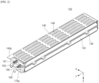
FIG. 1 is a perspective view of a battery cell assembly according to example embodiments of the present invention; -
FIG. 2 is a perspective view of a battery cell assembly according to example embodiments of the present invention; -
FIG. 3 is a cross-sectional view of a battery cell assembly according to example embodiments of the present invention; -
FIG. 4 is a conceptual view schematically illustrating a flow path of a first fluid in an upper cover plate of the battery cell assembly ofFIG. 1 ; -
FIG. 5A is a conceptual view schematically illustrating a flow path of a second fluid in a lower cover plate of the battery cell assembly ofFIG. 1 ; -
FIG. 5B is a cross-sectional view of the lower cover plate of the battery cell assembly ofFIG. 1 ; -
FIG. 6 is a perspective view of a first pipe of the battery cell assembly ofFIG. 1 ; -
FIG. 7 is a perspective view of a second pipe of the battery cell assembly ofFIG. 1 ; -
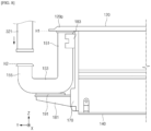
FIG. 8 is a side view schematically illustrating a part of the battery cell assembly ofFIG. 1 ; -
FIG. 9 is a cross-sectional view of a battery cell assembly according to example embodiments of the present invention; -
FIG. 10 is a cross-sectional view of a battery pack according to example embodiments of the present invention; and -
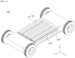
FIG. 11 is a schematic view of an electric vehicle in which a battery pack according to example embodiments of the present invention is mounted. - Hereinafter, embodiments of the present invention will be described in detail with reference to the accompanying drawings. Before describing embodiments of the present invention, the terms or expressions used in the present specification and claims should not be construed as being limited to as generally understood or as defined in commonly used dictionaries, and should be understood according to meanings and concepts matching corresponding to the present invention on the basis of the principle that the inventor(s) of the application can appropriately define the terms or expressions to optimally explain the present invention. The invention is defined in the appended claims.
- Well-known configurations or functions related to describing the present invention are not described in detail when it is determined that they would obscure the subject matter of the present invention due to unnecessary detail.
- Because embodiments of the present invention are provided to more fully explain the present invention to those of ordinary skill in the art, the shapes, sizes, etc. of components illustrated in the drawings may be exaggerated, omitted, or schematically illustrated for clarity. Therefore, it should not be understood that the sizes or proportions of components fully reflect the actual sizes or proportions thereof.
-
FIGS. 1 and2 are perspective views of abattery cell assembly 100 according to example embodiments of the present invention.FIGS. 1 and2 illustrate thebattery cell assembly 100 viewed from different directions.FIG. 3 is a cross-sectional view of thebattery cell assembly 100 according to example embodiments of the present invention.FIG. 4 is a conceptual view schematically illustrating a flow path of a first fluid in anupper cover plate 120 of thebattery cell assembly 100 ofFIG. 1 .FIG. 5A is a conceptual view schematically illustrating a flow path of a second fluid in alower cover plate 140 of thebattery cell assembly 100 ofFIG. 1 .FIG. 5B is a cross-sectional view of thelower cover plate 140 of thebattery cell assembly 100 ofFIG. 1 . - In accordance with claim 1, the
battery cell assembly 100 includes acell block 110, theupper cover plate 120, thelower cover plate 140. Referring toFIGS. 1 to 5B , thebattery cell assembly 100 may further includeside cover plates 130, andend plates 170. Theupper cover plate 120, and thelower cover plate 140, and optionally theside cover plates 130, may form a case CA of thebattery cell assembly 100 surrounding thecell block 110. - The
cell block 110 includes a plurality ofbattery cells 111. Each of thebattery cells 111 is a basic unit of a lithium ion battery, i.e., a secondary battery. Each of thebattery cells 111 may include an electrode assembly, an electrolyte, and a cell case. The electrode assembly provided in the cell case may include a positive electrode, a negative electrode, and a separator interposed between the positive electrode and the negative electrode. The electrode assembly may be a jelly-roll type electrode assembly or a stack type electrode assembly according to a form of assembly. The jelly roll type electrode assembly may include a structure in which a positive electrode, a negative electrode, and a separator interposed therebetween are wound together. The stack type electrode assembly may include a plurality of positive electrodes, a plurality of negative electrodes, and a plurality of separators interposed therebetween that are stacked sequentially. The positive electrodes may each include a positive electrode current collector and a positive electrode active material. The negative electrodes may each include a negative electrode current collector and a negative electrode active material. - The plurality of
battery cells 111 may be connected in series and/or in parallel. For example, the plurality ofbattery cells 111 may be connected to each other in series. For example, the plurality ofbattery cells 111 may be connected to each other in parallel. For example, when a set of two ormore battery cells 111 connected in parallel is defined as a bank, one bank including two ormore battery cells 111 connected in parallel and another bank including two ormore battery cells 111 connected in parallel may be connected in series. - Each of the
battery cells 111 may be a pouch type battery cell, a cylindrical battery cell, or a prismatic battery cell. An electrode assembly of the pouch type battery cell is embedded in a pouch case including an aluminum laminate sheet. An electrode assembly of the cylindrical battery cell is embedded in a cylindrical metal can. An electrode assembly of the prismatic battery cell is embedded in a prismatic metal can. - In example embodiments, the plurality of
battery cells 111 may be pouch type battery cells and be stacked in onebattery cell assembly 100 in a first direction (an X-axis direction). In example embodiments, in eachbattery cell assembly 100, the plurality ofbattery cells 111 may be pouch type battery cells whose length in the first direction (the X-axis direction) is less than a length thereof in a second direction (a Y-axis direction) and be stacked in the first direction (the X-axis direction). - When viewed from a plane, the
cell block 110 may have a rectangular shape whose length in the first direction (the X-axis direction) is less than a length thereof in the second direction (the Y-axis direction). In this case, thecell block 110 may have two lateral sides (i.e., a first lateral side and a second lateral side) facing each other in the first direction (the X-axis direction), a front side and a rear side facing each other in the second direction (the Y-axis direction), and an upper side and a lower side facing each other in a vertical direction (a Z-axis direction). - A bus bar frame on which bus bars are mounted may be disposed on each of the front and rear sides of the
cell block 110. A plurality of bus bars may be mounted on the bus bar frame on the front side of thecell block 110, and a plurality of bus bars may be mounted on the bus bar frame on the rear side of thecell block 110. - An
end plate 170 may be disposed on each of the front and rear sides of thecell block 110. Theend plate 170 on the front side of thecell block 110 may cover the bus bar frame on the front side of thecell block 110, and theend plate 170 on the rear side of thecell block 110 may cover the bus bar frame on the rear side of thecell block 110. - A bus bar may be coupled to electrode leads of the
battery cell 111. For example, the bus bar may be coupled to the electrode leads of thebattery cell 111 by welding. For example, each bus bar may be an inter-bus bar coupled to electrode leads coupled todifferent battery cells 111 belonging to thecell block 110 to electrically connect thedifferent battery cells 111. For example, each bus bar may be a terminal bus bar for electrically coupling thebattery cell assembly 100 to anotherbattery cell assembly 100 or another electrical device. - In example embodiments, the
battery cell assembly 100 may include asingle cell block 110. In example embodiments, thebattery cell assembly 100 may include a cell block array with a plurality ofcell blocks 110 arranged in the second direction (the Y-axis direction). For example, thebattery cell assembly 100 may include twocell blocks 110 arranged in the second direction (the Y-axis direction). For example, thebattery cell assembly 100 may include a first cell block and a second cell block that are arranged in the case CA to be spaced apart from each other in the second direction (the Y-axis direction) and electrically connected to each other. - An
upper cover plate 120 may at least partially cover the upper side of thecell block 110. Theupper cover plate 120 may be coupled to upper ends of twoside cover plates 130 on both sides of thecell block 110. For example, one lateral part of theupper cover plate 120 may be coupled to the upper end of one of theside cover plates 130 by welding, and another lateral part thereof may be coupled to the upper end of the otherside cover plate 130 by welding. - The
upper cover plate 120 faces the upper side of thecell block 110. Theupper cover plate 120 may be attached to the upper side of thecell block 110 and be thermally coupled to thecell block 110. For example, theupper cover plate 120 may be attached to the upper side of thecell block 110 through a thermally conductive adhesive layer interposed between theupper cover plate 120 and the upper side of thecell block 110. For example, the thermally conductive adhesive layer may include a thermal interface material (TIM). - The
upper cover plate 120 includes afirst cooling channel 123 configured to allow a first fluid to flow therethrough and be configured to cool thecell block 110. Thefirst cooling channel 123 defines a passage for the first fluid. Thefirst cooling channel 123 may have a single path extending from an inlet thereof to an outlet thereof. While the first fluid flows along thefirst cooling channel 123, thebattery cell assembly 100 may be cooled. For example, theupper cover plate 120 may be manufactured by bonding two plates, and thefirst cooling channel 123 may include a space defined between the two plates. That is, the coolingchannel 123 may be located inside of theupper cover plate 120. The first fluid may include coolant or a refrigerant. The first fluid can thus be a cooling fluid. - The
upper cover plate 120 may include a firstupper port 1231 to which afirst pipe 150 is connected and a secondupper port 1233 to which asecond pipe 160 is connected. One of the firstupper port 1231 and the secondupper port 1233 of theupper cover plate 120 may include the inlet of thefirst cooling channel 123 into which the first fluid is introduced, and the other may include the outlet of thefirst cooling channel 123 from which the first fluid is discharged. As illustrated inFig. 4 , both the firstupper port 1231 and the secondupper port 1233 of theupper cover plate 120 are located at the same side of theupper cover plate 120. That is, the inlet and the outlet of the first fluid are located at the same side of theupper cover plate 120. Alternatively, in some embodiments, the firstupper port 1231 and the secondupper port 1233 of theupper cover plate 120 may be located at different sides of theupper cover plate 120, such as at the opposite sides of theupper cover plate 120 in the longitudinal direction of the upper cover plate 120 (that is opposite side in the direction of the y-axis). That is, the inlet and the outlet of the first fluid may be located at different sides of theupper cover plate 120, such as at opposite sides of theupper cover plate 120. - In example embodiments, the first
upper port 1231 of theupper cover plate 120 may include the inlet of thefirst cooling channel 123, and the secondupper port 1233 thereof may include the outlet of thefirst cooling channel 123. The first fluid provided from an external fluid supply CS may be transferred to aninlet 159 of thefirst pipe 150 through a flow path of afirst transfer pipe 301, and may flow along aflow path 157 of thefirst pipe 150, the firstupper port 1231 of theupper cover plate 120, thefirst cooling channel 123, the secondupper port 1233 of theupper cover plate 120, and aflow path 167 of thesecond pipe 160. Thereafter, the first fluid may be discharged to asecond transfer pipe 302 through anoutlet 169 of thesecond pipe 160 and recovered to the external fluid supply CS through thesecond transfer pipe 302. - The
upper cover plate 120 may include aprotruding part 120p protruding from thecell block 110 to one side. For example, the protrudingpart 120p of theupper cover plate 120 may protrude from the front side of thecell block 110 in the second direction (the Y-axis direction). Both the firstupper port 1231 and the secondupper port 1233 of theupper cover plate 120 may be provided on the protrudingpart 120p of theupper cover plate 120. Both the firstupper port 1231 and the secondupper port 1233 of theupper cover plate 120 may be provided on a lower side of theprotruding part 120p of theupper cover plate 120. - One of the two
side cover plates 130 may cover the first lateral side of thecell block 110, and the other may cover the second lateral side of thecell block 110. Thebattery cell assembly 100 may be fastened to an external pack housing 501 (seeFIG. 9 ) in a side mounting manner. For example, each of theside cover plates 130 may include one ormore fastening flanges 139 protruding in the first direction (the X-axis direction). Thefastening flange 139 may be provided with a fastening hole through which a fastening member such as a bolt passes. Thefastening flange 139 may be fastened and supported on a support structure of thepack housing 501 by a fastening member such as a bolt. - The
lower cover plate 140 is disposed to face the lower side of thecell block 110. Thelower cover plate 140 may at least partially cover the lower side of thecell block 110. Thelower cover plate 140 may be coupled to lower ends of the twoside cover plates 130 on both sides of thecell block 110. For example, one lateral part of thelower cover plate 140 may be coupled to the lower end of one of theside cover plates 130 by welding, and another lateral part thereof may be coupled to the lower end of the otherside cover plate 130 by welding. Thelower cover plate 140, theupper cover plate 120, and optionally theside cover plates 130 may form a case CA surrounding four surfaces (e.g., the upper side, the lower side, the first lateral side, and the second lateral side) of thecell block 110. - The
lower cover plate 140 may be attached to the lower side of thecell block 110 and be thermally coupled to thecell block 110. For example, thelower cover plate 140 may be attached to the lower side of thecell block 110 through a thermally conductive adhesive layer interposed between thelower cover plate 140 and the lower side of thecell block 110. For example, the thermally conductive adhesive layer may include the TIM. - The
lower cover plate 140 includes asecond cooling channel 143 configured to allow a second fluid to flow therethrough and be configured to cool thecell block 110. Thesecond cooling channel 143 defines a passage for the second fluid. For example, as illustrated inFig. 5B thesecond cooling channel 143 may be located inside of thecover plate 140. Thesecond cooling channel 143 may have a single path extending from an inlet thereof to an outlet thereof. While the second fluid flows along thesecond cooling channel 143, thebattery cell assembly 100 may be cooled. The second fluid may include coolant or a refrigerant. The second fluid can thus be a cooling fluid. The second fluid may be the same as or different from the first fluid. - The
lower cover plate 140 may include a firstlower port 1431 and a secondlower port 1433. One of the firstlower port 1431 and the secondlower port 1433 of thelower cover plate 140 may include the inlet of thesecond cooling channel 143 into which the second fluid is introduced, and the other may include the outlet of thesecond cooling channel 143 from which the second fluid is discharged. In example embodiments, the firstlower port 1431 of thelower cover plate 140 may include the inlet of thesecond cooling channel 143, and the secondlower port 1433 thereof may include the outlet of thesecond cooling channel 143. The second fluid provided from the external fluid supply CS may be transferred to the firstlower port 1431 of thelower cover plate 140 through a flow path of athird transfer pipe 303, and may flow from the firstlower port 1431 to the secondlower port 1433 along thesecond cooling channel 143. The second fluid discharged from thelower cover plate 140 may be recovered to the external fluid supply CS through afourth transfer pipe 304. - The
lower cover plate 140 may include aprotruding part 140p protruding from thecell block 110 to one side. For example, the protrudingpart 140p of thelower cover plate 140 may protrude from the front side of thecell block 110 in the second direction (the Y-axis direction). Both the firstlower port 1431 and the secondlower port 1433 of thelower cover plate 140 may be provided on the protrudingpart 140p of thelower cover plate 140. Both the firstlower port 1431 and the secondlower port 1433 of thelower cover plate 140 may be provided on an upper side of theprotruding part 140p of thelower cover plate 140. - The
lower cover plate 140 is provided with aventing hole 149 for exhausting a high-temperature gas caused by thecell block 110 to a space under thecell block 110. Thelower cover plate 140 may include a plurality of ventingholes 149 arranged in the first direction (the X-axis direction) and the second direction (the Y-axis direction). A part of the lower side of thecell block 110 is thus exposed to the outside of thebattery cell assembly 100 through the at least oneventing hole 149 of thelower cover plate 140. As can be seen fromFig. 5B the venting holes 149 are preferably arranged such that the coolingchannel 143 is located between the venting holes 149. - According to example embodiments of the present invention, the
battery cell assembly 100 has a multi-faceted cooling structure for simultaneously cooling multiple surfaces of thebattery cell assembly 100, thereby reducing heat deviation and temperature deviation between thebattery cells 111. Accordingly, temperatures of thebattery cells 111 and thebattery cell assembly 100 may be more uniformly controlled, thereby improving the safety and reliability of thebattery cell assembly 100 and the battery pack including thebattery cell assembly 100. - According to example embodiments of the present invention, a venting hole is provided in the case CA of the
battery cell assembly 100 to discharge a high-temperature gas or flames, thereby ensuring safety in a thermal runaway event. - According to example embodiments of the present invention, a cooling plate (e.g., the lower cover plate 140) of the case CA of the
battery cell assembly 100 is provided with a function of cooling thebattery cells 111 and a function of discharging a high-temperature gas through the venting hole and thus a thermal propagation may be effectively delayed and suppressed. Therefore, the safety and reliability of the battery cell assembly and a battery pack including the same can improve. - According to example embodiments of the present invention, the
battery cell assembly 100 has the multi-faceted cooling structure and a venting function and thus an increase of temperature of thebattery cells 111 can be alleviated during quick charging. Accordingly, a derating issue caused by an increase of temperature of thebattery cells 111 can be reduced or prevented, and a customer demand for shortening a quick charging time can be satisfied. -
FIG. 6 is a perspective view of thefirst pipe 150 of thebattery cell assembly 100 ofFIG. 1 .FIG. 7 is a perspective view of thesecond pipe 160 of thebattery cell assembly 100 ofFIG. 1 .FIG. 8 is a side view schematically illustrating a part of thebattery cell assembly 100 ofFIG. 1 . - Referring to
FIGS. 6 to 8 together withFIGS. 1 to 5B , thefirst pipe 150 may be connected to the firstupper port 1231 of theupper cover plate 120, and thesecond pipe 160 may be connected to the secondupper port 1233 of theupper cover plate 120. In example embodiments, thefirst pipe 150 may be coupled to the firstupper port 1231 of theupper cover plate 120 by welding, and thesecond pipe 160 may be coupled to the secondupper port 1233 of theupper cover plate 120 by welding. Thefirst pipe 150 may be a supply pipe configured to supply the first fluid provided from the outside to thefirst cooling channel 123 of theupper cover plate 120, and thesecond pipe 160 may be a discharge pipe configured to discharge the first fluid discharged from thefirst cooling channel 123 of theupper cover plate 120 to the outside. - The
first pipe 150 may be supplied with the first fluid from the external fluid supply unit CS through thefirst transfer pipe 301, and transfer the first fluid to the firstupper port 1231 of theupper cover plate 120. Thefirst pipe 150 may provide asingle flow path 157 extending from one end thereof connected to thefirst transfer pipe 301 to another end thereof connected to the firstupper port 1231 of theupper cover plate 120. - When viewed from a side view, the
first pipe 150 may have a roughly U-shape. More specifically, thefirst pipe 150 may include afirst part 151 extending downward from the firstupper port 1231 of theupper cover plate 120, asecond part 153 extending from thefirst part 151 in a direction crossing a direction in which thefirst part 151 extends, and athird part 155 extending upward from thesecond part 153. Anoutlet 158 connected to the firstupper port 1231 of theupper cover plate 120 may be provided at an upper end of thefirst part 151 of thefirst pipe 150, and aninlet 159 through which the first fluid supplied from the outside is introduced may be provided at an upper end of thethird part 155 of thefirst pipe 150. The upper end of thethird part 155 of thefirst pipe 150 may be an end of thefirst pipe 150. Thefirst pipe 150 may be attached to a lower side of theupper cover plate 120, and an entire part thereof may be below theupper cover plate 120. - The
second pipe 160 may discharge the first fluid discharged from theupper cover plate 120 to thesecond transfer pipe 302, and the first fluid may be transferred to the external fluid supply CS through thesecond transfer pipe 302. Thesecond pipe 160 may provide asingle flow path 167 extending from one end thereof connected to thesecond transfer pipe 302 to another end thereof connected to the secondupper port 1233 of theupper cover plate 120. - When viewed from a side view, the
second pipe 160 may have a roughly U-shape. More specifically, thesecond pipe 160 may include afourth part 161 extending downward from the secondupper port 1233 of theupper cover plate 120, afifth part 163 extending from thefourth part 161 in a direction crossing a direction in which thefourth part 161 extends, and asixth part 165 extending upward from thesixth part 163. Aninlet 168 connected to the secondupper port 1233 of theupper cover plate 120 may be provided at an upper end of thefourth part 161 of thesecond pipe 160, and anoutlet 169 for discharging the first fluid may be provided at an upper end of thesixth part 165 of thesecond pipe 160. The upper end of thesixth part 165 of thesecond pipe 160 may be an end of thesecond pipe 160. Thesecond pipe 160 may be attached to the lower side of theupper cover plate 120, and an entire part thereof may be below theupper cover plate 120. - A technical advantage of the roughly U-shape of the
first pipe 150 and/or of thesecond pipe 160 is that it ensures easier installation of thebattery cell assembly 100 into its final location, such as into an electric vehicle ofFig. 11 . For example, when thebattery cell assembly 100 is mounted in thevehicle 1000 ofFig. 11 , it can be seen that the connection between the pipe supplying the first fluid and thefirst pipe 150 and the connection between the pipe discharging the first fluid and thesecond pipe 160 is established from the area above thebattery cell assembly 100. That is, since the area below thebattery cell assembly 100 is blocked by thebody frame 1200, it cannot generally be reached by the technician who is assembling the vehicle. The technician thus establishes the connection between the pipes by reaching down from the area above thebattery cell assembly 100. The U-shape of thefirst pipe 150 and/or of thesecond pipe 160 ensures that theinlet 159 and theoutlet 169 both face toward the upper direction along the vertical axis. The U-shape thus facilitates easier manufacturing process of the vehicle carrying thebattery cell assembly 100. - The
battery cell assembly 100 may include a firstbottom support 181 for supporting thefirst pipe 150 and a secondbottom support 185 for supporting thesecond pipe 160. The firstbottom support 181 and the secondbottom support 185 may be provided to theend plate 170 on the front side of thecell block 110. In example embodiments, each of the firstbottom support 181 and the secondbottom support 185 may be a part of theend plate 170. The firstbottom support 181 may be disposed below thesecond part 153 of thefirst pipe 150 and support a lower portion of thesecond part 153 of thefirst pipe 150. The secondbottom support 185 may be disposed below thefifth part 163 of thesecond pipe 160 and support a lower portion of thefifth part 163 of thesecond pipe 160. - In example embodiments, a first
elastic pad 191 may be provided between the firstbottom support 181 and thesecond part 153 of thefirst pipe 150. In example embodiments, a secondelastic pad 193 may be provided between the secondbottom support 185 and thefifth part 163 of thesecond pipe 160. - The
battery cell assembly 100 may include afirst side support 183 for supporting a lateral side of thefirst pipe 150 and a second side support (not shown) for supporting a lateral side of thesecond pipe 160. Each of thefirst side support 183 and the second side support may be a part of theend plate 170. Thefirst side support 183 may support and be in contact with a lateral portion of thefirst part 151 of thefirst pipe 150. Thefirst part 151 of thefirst pipe 150 may be inserted into a groove provided in thefirst side support 183. The second side support may support and be in contact with a lateral portion of thefourth part 161 of thesecond pipe 160. Thefourth part 161 of thesecond pipe 160 may be inserted into a groove provided in the second side support. - A position H2 of an upper end of the
third part 155 of thefirst pipe 150 in the vertical direction (the Z-axis direction) may be lower than a position H1 of the lower side of theupper cover plate 120 in the vertical direction (the Z-axis direction). Similarly, a position of thesixth part 165 of thesecond pipe 160 in the vertical direction (the Z-axis direction) may be lower than the position H1 of the lower side of theupper cover plate 120 in the vertical direction (the Z-axis direction). When pipes for transferring the first fluid are attached to the upper side of theupper cover plate 120, a total thickness of thebattery cell assembly 100 may increase and a space occupied by eachbattery cell assembly 100 may increase, thus resulting in a reduction of the energy density of a battery pack. However, according to embodiments, the entire first andsecond pipes upper cover plate 120 and thus thebattery cell assembly 100 with a cooling function can be provided without causing an energy density reduction issue. - In addition, in embodiments, the
first pipe 150 is attached to the lower side of theupper cover plate 120, and the firstbottom support 181 may support the lower portion of thefirst pipe 150. When avalve 321 is mounted on an end of thefirst pipe 150, an external force applied to the end of thefirst pipe 150 causes thefirst pipe 150 to pivot about a joint between thefirst pipe 150 and theupper cover plate 120. The joint (e.g., a welded area) between thefirst pipe 150 and theupper cover plate 120 may be broken or damaged due to the pivot of thefirst pipe 150. - However, according to embodiments of the present invention, the first
bottom support 181 may support the lower portion of thefirst pipe 150 to prevent thefirst pipe 150 from pivoting by an external force applied when thevalve 321 is mounted on the end of thefirst pipe 150. Similarly, the secondbottom support 185 may support the lower portion of thesecond pipe 160 to prevent thesecond pipe 160 from pivoting by an external force applied when a valve is mounted on an end of thesecond pipe 160. According to embodiments, the joint reliability between pipes (i.e., thefirst pipe 150 and the second pipe 160) for supplying and discharging the first fluid and a cooling plate (i.e., the upper cover plate 120) can be improved. Therefore, the reliability of the cooling performance of thebattery cell assembly 100 may be improved, and the safety and reliability of thebattery cell assembly 100 may be improved. -
FIG. 9 is a cross-sectional view of abattery cell assembly 100A according to example embodiments of the present invention. Hereinafter, thebattery cell assembly 100A ofFIG. 9 will be described focusing on differences from thebattery cell assembly 100 described above with reference toFIGS. 1 to 5B . - Referring to
FIG. 9 , anupper cover plate 120A may be provided with aventing hole 129 for exhausting a high-temperature gas generated from acell block 110 to an external space of thecell block 110. Theupper cover plate 120A may include a plurality of ventingholes 129 arranged in the first direction (the X-axis direction) and the second direction (the Y-axis direction). A part of an upper side of thecell block 110 may be exposed to the outside of thebattery cell assembly 100A through the plurality of ventingholes 129 of theupper cover plate 120A. -
FIG. 10 is a cross-sectional view of abattery pack 500 according to example embodiments of the present invention. - Referring to
FIG. 10 , thebattery pack 500 may include apack housing 501 and abattery cell assembly 100 mounted in thepack housing 501. Thebattery pack 500 may include one or morebattery cell assemblies 100 mounted in thepack housing 501. In example embodiments, thebattery pack 500 may include two or morebattery cell assemblies 100 arranged in the first direction (the X-axis direction). - The
pack housing 501 may include alower housing 510 with an accommodation space in which thebattery cell assembly 100 is accommodated, and apack lid 520 coupled on thelower housing 510 to cover thelower housing 510 in which thebattery cell assembly 100 is accommodated. The accommodation space of thelower housing 510 may be defined by abottom wall 511 facing a lower side of thecell block 110 of eachbattery cell assembly 100 andside walls 513 extending along the perimeter of thebottom wall 511. - When the
battery pack 500 is mounted in a vehicle, a cabin room in which a passenger rides may be located above thepack lid 520, and a ground on which the vehicle travels may be located below thelower housing 510. - The
battery cell assembly 100 may be mounted in thepack housing 501 in the side mounting manner. More specifically, afastening flange 139 of each side cover plate may be fastened and supported on acorresponding support structure 515 amongsupport structures 515 provided on thelower housing 510 through a bolt BT. - A free volume FV may be provided between the
bottom wall 511 of thelower housing 510 and thebattery cell assembly 100. The free volume FV may be understood as an empty space between each of a plurality ofbattery cell assemblies 100 and thelower housing 510. The free volume FV may be referred to as a space, a buffer space, or a venting space. Alower cover plate 140 of eachbattery cell assembly 100 and thebottom wall 511 of thelower housing 510 may be spaced apart from each other with the free volume FV therebetween. The lower side of thecell block 110 may be exposed toward the free volume FV through aventing hole 149 of thelower cover plate 140. A gas and flames generated in a thermal runaway situation may move through the free volume FV. That is, the free volume FV functions as a venting passage through which a high-temperature gas and flames move. - Even when a strong impact is generated due to a foreign material splashing to a lower part of a vehicle in a hard ground driving situation such as a non-paved road, the impact can be absorbed through the free volume FV. Therefore, a plurality of
battery cell assemblies 100 can be prevented from being damaged due to the impact. The free volume FV may be available as a space for freely allowing deformation of thelower housing 510 to some extent when thelower housing 510 deforms toward thebattery cell assembly 100 due to an impact applied to the lower part of the vehicle. - A height of the free volume FV and the distance between the bottom wall of the
lower housing 510 and thebattery cell assembly 100 may be determined enough to absorb external impact. The height of the free volume FV may be determined in consideration of dimensions and rigidity of the frames of the vehicle, dimensions and rigidity of thelower housing 510, dimensions of thebattery pack 500, the amount of a generated gas and a gas discharge speed during thermal runaway, and the like. For example, when the thickness or rigidity of the frames of the vehicle or the bottom wall of thelower housing 510 is relatively large, at least one of the size and height of the free volume FV may be relatively reduced. When the thickness or rigidity of the frames of the vehicle or the bottom wall of thelower housing 510 is relatively small, the bottom wall of thelower housing 510 is highly likely to deform and thus at least one of the size and height of the free volume FV may be relatively increased to protect thebattery cell assembly 100. When the size of thebattery pack 500 is relatively large compared to the standards of thebattery pack 500, a relatively large free volume FV can be secured. When the size of thebattery pack 500 is relatively small, a height of the free volume FV to be secured may be relatively small and thus the thickness and rigidity of the bottom wall of thelower housing 510 may have to be relatively increased. When the height of the free volume FV is extremely small, a gas discharge passage may be small and thus internal pressure of thebattery pack 500 may increase sharply during thermal runaway. Accordingly, the size and height of the free volume FV may be determined in consideration of the amount of a generated gas and the gas discharge speed. - A maximum height of the free volume FV may be determined according to a degree of damage to the
battery cells 111 included in thebattery cell assembly 100. For example, when a damage tolerance limit of thebattery cell 111 is 1 mm, the free volume FV may be determined to prevent thebattery cell 111 from deforming by more than 1 mm when thelower housing 510 deforms and pressurizes a lower side of thebattery cell 111. In this case, the amount of deformation of thelower housing 510 may vary according to the thickness or rigidity of thelower housing 510. Therefore, the size or height of the free volume FV may be determined in consideration of all the damage tolerance limit of thebattery cell 111 and the thickness and rigidity of thelower housing 510. - In example embodiments, an upper side of the
battery cell assembly 100 may be in close contact with a lower side of thepack lid 520. When there is a space between thebattery cell assembly 100 and thepack lid 520, a high-temperature gas may be introduced into the space between thebattery cell assembly 100 and thepack lid 520 during thermal runaway and thus heat and flames may propagate to another adjacentbattery cell assembly 100. The heat and the flames are also transferred to thepack lid 520 and thus may affect the cabin room above thepack lid 520. Therefore, a gas or flames generated in thebattery pack 500 may be guided to the free volume FV by bringing the upper side of thebattery cell assembly 100 and the lower side of thepack lid 520 into close contact with each other. -
FIG. 11 is a schematic view of anelectric vehicle 1000 in which abattery pack 1100 according to example embodiments of the present invention is mounted. - For the sake of simplicity,
FIG. 11 illustrates only avehicle body frame 1200 forming a lower frame of a vehicle, and abattery pack 1100 and tires that are coupled to thevehicle body frame 1200. For example, thebattery pack 1100 may include thebattery pack 500 described above with reference toFIG. 10 . - In the case of a general battery pack, battery cell assemblies are installed at the bottom of a pack housing of the battery pack. In embodiments, the free volume FV (see
FIG. 10 ) may be provided under thebattery cell assemblies 100 of thebattery pack 1100. By bringing thebattery cell assembly 100 and thepack lid 520 into close contact with each other, a gas generated from thebattery cell assembly 100 may be guided to the free volume FV rather than the cabin room of the vehicle. The gas may be guided to the free volume FV provided in thebattery cell assembly 100 and a pack housing of thebattery pack 1100. The gas may flow through the free volume FV and be discharged to the lower or lateral side of the vehicle through a gas exhaust installed in thebattery pack 1100. In addition, according to the present embodiments, in thebattery pack 1100, the free volume FV is provided between thebattery cell assembly 100 and the pack housing and thus thebattery cell assembly 100 can be prevented from being damaged regardless of the deformation of the pack housing. - According to embodiments of the present invention, the safety of passengers can be strengthened owing to the
battery pack 1100 and theelectric vehicle 1000 including the same. In addition, thebattery cell assembly 100 that is a key component can be protected and the durability of thebattery pack 1100 and theelectric vehicle 1000 can be enhanced. - According to example embodiments of the present invention, a battery cell assembly has a multi-faceted cooling structure for simultaneously cooling multiple surfaces of the battery cell assembly, thereby reducing heat deviation and temperature deviation between battery cells. Ultimately, temperatures of the battery cells and the battery cell assembly can be more uniformly controlled to improve the safety and reliability of the battery cell assembly and the battery pack including the same.
- According to example embodiments of the present invention, a venting hole is provided in a case of the battery cell assembly to discharge a high-temperature gas or flames, thereby ensuring safety in a thermal runaway event.
- According to example embodiments of the present invention, a cooling plate included in a case of a battery cell assembly has a function of cooling battery cells and a function of exhausting a high-temperature gas through a venting hole and thus thermal propagation can be effectively delayed and suppressed. Therefore, the safety and reliability of the battery cell assembly and a battery pack including the same can improve.
- According to example embodiments of the present invention, a battery cell assembly has the multi-faceted cooling structure and a venting function and thus an increase of temperature of battery cells can be alleviated during quick charging. Accordingly, a derating issue caused by an increase of temperature of the battery cells can be reduced or prevented, and a customer demand for shortening a quick charging time can be satisfied.
- Effects achievable from example embodiments of the present invention are not limited to the above-described effects, and other effects that are not described herein will be clearly derived and understood by those of ordinary skilled in the art to which the example embodiments of the present invention pertain from the following description. That is, unintended effects achieved when the example embodiments of the present invention are implemented are derivable by those of ordinary skilled in the art from the example embodiments of the present invention.
- The present invention has been described above in more detail with reference to the drawings, the embodiments, etc. However, the configurations illustrated in the drawings or embodiments described in the present specification are only exemplary embodiments, while the actual invention is defined in the appended claims.
Claims (15)
- A battery cell assembly (100) comprising:a cell block (110) including a plurality of battery cells (111); anda case (CA) configured to accommodate the cell block (110),wherein the case (CA) comprises:an upper cover plate (120) facing an upper side of the cell block (110) and including a first cooling channel (123) configured such that a first fluid flows therethrough; anda lower cover plate (140) facing a lower side of the cell block (110), and including a venting hole (149) and a second cooling channel configured such that (143) a second fluid flows therethrough.
- The battery cell assembly (100) of claim 1, wherein a part of the lower side of the cell block (110) is exposed to the outside through the venting hole (149) of the lower cover plate (140).
- The battery cell assembly (100) of claim 1 or 2, wherein the upper cover plate (120) further comprises a venting hole (129).
- The battery cell assembly (100) of claim 3, wherein a part of the upper side of the cell block (110) is exposed to the outside through the venting hole (129) of the upper cover plate (120).
- The battery cell assembly (100) of any one of claims 1-4, wherein the upper cover plate (120) further comprises a protruding part (120p) protruding from a side of the cell block (110), andthe battery cell assembly (100) further comprises a first pipe (150) connected to a first upper port (1231) on a lower side of the protruding part (120p) and configured to transfer the first fluid,wherein the first pipe (150) comprises:a first part (151) extending downward from the first upper port (1231) of the upper cover plate (120);a second part (153) extending from the first part (151) in a direction crossing a direction in which the first part (151) extends; anda third part (155) extending upward from the second part (153).
- The battery cell assembly (100) of claim 5, further comprising a first bottom support (181) provided below the second part (153) of the first pipe (150) and configured to support the second part (153) of the first pipe (150).
- The battery cell assembly (100) of claim 6, further comprising a first elastic pad (191) provided between the second part (153) of the first pipe (150) and the first bottom support (181).
- The battery cell assembly (100) of any one of claims 5-7, wherein an upper end of the third part (155) of the first pipe (150) is an end of the first pipe (150) and is located below the first upper port (1231) of the upper cover plate (120).
- The battery cell assembly (100) of any one of claims 5-8, further comprising a second pipe (160) connected to a second upper port (1233) on the lower side of the protruding part (120p) of the upper cover plate (120), and configured to transfer the first fluid, andwherein one of the first pipe (150) and the second pipe (160) is configured to transfer the first fluid supplied from the outside to the first cooling channel (123) of the upper cover plate (120), and the other first or second pipe (150, 160) is configured to transfer the first fluid discharged from the first cooling channel (123) of the upper cover plate (120) to the outside,the second pipe (160) comprises:a fourth part (161) extending downward from the second upper port (1233) of the upper cover plate (120);a fifth part (163) extending from the fourth part (161) in a direction crossing a direction in which the fourth part (161) extends; anda sixth part (165) extending upward from the fifth part (163),an upper end of the sixth part (165) of the second pipe (160) is an end of the second pipe (160), and is located below the second upper port (1233) of the upper cover plate (120).
- The battery cell assembly (100) of claim 9, further comprising:a second bottom support (185) provided below the fifth part (163) of the second pipe (160) and configured to support the fifth part (163) of the second pipe (160); anda second elastic pad (193) provided between the fifth part (163) of the second pipe (160) and the second bottom support (185).
- The battery cell assembly (100) of any one of claims 1-10, wherein the lower cover plate (140) further comprises a protruding part (140p) protruding from a side of the cell block (110), and
an upper end of the protruding part (140p) of the lower cover plate (140) is provided with a first lower port (1431) into which the second fluid is introduced and a second lower port (1433) from which the second fluid is discharged. - The battery cell assembly (100) of any one of claims 1-11, wherein the case (CA) further comprises a side cover plate (130) facing a lateral side of the cell block (110),
wherein the side cover plate (130) is coupled to the upper cover plate (120) and the lower cover plate (140) and comprises a fastening flange (139) configured to be fastened to an external support structure. - A battery pack (500) comprising:a pack housing (501); anda battery cell assembly (100) accommodated in the pack housing (501), and including a cell block (110) with a plurality of battery cells (111) and a case (CA) configured to accommodate the cell block (110),wherein the case (CA) comprises:an upper cover plate (120) facing an upper side of the cell block (110) and including a first cooling channel (123) configured such that a first fluid flows therethrough; anda lower cover plate (140) facing a lower side of the cell block (110), and including a venting hole (149) and a second cooling channel (143) configured such that a second fluid flows therethrough.
- The battery pack (500) of claim 13, wherein the case (CA) further comprises a side cover plate (130) facing a lateral side of the cell block (110),wherein the side cover plate (130) comprises a fastening flange (139) configured to be fastened to a support structure on a bottom wall of the pack housing (501),the lower cover plate (140) of the battery cell assembly (100) is spaced apart from the bottom wall of the pack housing (501) with a first space interposed therebetween, andthe lower side of the cell block (110) is exposed toward the first space through the venting hole (149).
- The battery pack (500) of claim 13 or 14, wherein the upper cover plate (120) further comprises a protruding part (120p) protruding from a side of the cell block (110), and
the battery cell assembly (100) further comprises:a first pipe (150) connected to a first upper port (1231) on a lower side of the protruding part (120p) and configured to transfer the first fluid supplied from the outside to the first cooling channel (123); anda second pipe (160) connected to a second upper port (1233) on the lower side of the protruding part (120p) of the upper cover plate (120) and configured to transfer the first fluid discharged from the first cooling channel (123) to the outside.
Applications Claiming Priority (1)
| Application Number | Priority Date | Filing Date | Title |
|---|---|---|---|
| KR20230122363 | 2023-09-14 |
Publications (2)
| Publication Number | Publication Date |
|---|---|
| EP4525143A1 true EP4525143A1 (en) | 2025-03-19 |
| EP4525143B1 EP4525143B1 (en) | 2026-02-04 |
Family
ID=92301117
Family Applications (1)
| Application Number | Title | Priority Date | Filing Date |
|---|---|---|---|
| EP24193920.6A Active EP4525143B1 (en) | 2023-09-14 | 2024-08-09 | Battery cell assembly and battery pack including the same |
Country Status (7)
| Country | Link |
|---|---|
| EP (1) | EP4525143B1 (en) |
| JP (1) | JP2025539082A (en) |
| KR (1) | KR20250039918A (en) |
| CN (1) | CN120202581A (en) |
| ES (1) | ES3063836T3 (en) |
| PL (1) | PL4525143T3 (en) |
| WO (1) | WO2025058389A1 (en) |
Citations (8)
| Publication number | Priority date | Publication date | Assignee | Title |
|---|---|---|---|---|
| KR102218473B1 (en) | 2018-01-19 | 2021-02-23 | 한온시스템 주식회사 | Battery cooling plate with integrated air vents |
| CN113994524A (en) * | 2019-04-15 | 2022-01-28 | 罗伯特·博世有限公司 | Battery pack with thermal management system |
| WO2022223892A1 (en) * | 2021-04-20 | 2022-10-27 | Psa Automobiles Sa | Electrical power storage battery system comprising a safety venting system |
| US20220361367A1 (en) * | 2021-05-04 | 2022-11-10 | Rimac Automobiles Ltd. | Cold plate assembly |
| KR20220169831A (en) | 2021-06-21 | 2022-12-28 | 주식회사 엘지에너지솔루션 | Battery pack with improved gas venting path |
| KR20230028037A (en) | 2021-08-20 | 2023-02-28 | 현대모비스 주식회사 | Cooling device for high voltage battery |
| EP4199215A1 (en) * | 2021-03-23 | 2023-06-21 | LG Energy Solution, Ltd. | Battery module having structure for preventing heat dissipation in battery cells using coolant, and battery pack comprising same |
| KR20230104442A (en) | 2021-12-31 | 2023-07-10 | 서진산업 주식회사 | Battery case for electric vehicle with improved cooling function of battery |
Family Cites Families (5)
| Publication number | Priority date | Publication date | Assignee | Title |
|---|---|---|---|---|
| JP5343048B2 (en) * | 2010-07-29 | 2013-11-13 | 日立ビークルエナジー株式会社 | Power storage module and power storage device |
| JP5777734B2 (en) * | 2011-02-22 | 2015-09-09 | エルジー ケム. エルティーディ. | Cooling member with improved cooling efficiency and battery module using the same |
| KR102256104B1 (en) * | 2017-04-07 | 2021-06-03 | 주식회사 엘지에너지솔루션 | Battery module, battery pack comprising the battery module and vehicle comprising the battery pack |
| JP7049892B2 (en) * | 2018-04-04 | 2022-04-07 | 昭和電工株式会社 | Cooling and heating device for assembled batteries |
| KR102690299B1 (en) * | 2020-06-29 | 2024-08-01 | 주식회사 엘지에너지솔루션 | Battery Module Comprising Heat Dissipation Member and Method for Preparing the Heat Dissipation Member |
-
2024
- 2024-08-09 PL PL24193920.6T patent/PL4525143T3/en unknown
- 2024-08-09 ES ES24193920T patent/ES3063836T3/en active Active
- 2024-08-09 EP EP24193920.6A patent/EP4525143B1/en active Active
- 2024-09-11 JP JP2025527116A patent/JP2025539082A/en active Pending
- 2024-09-11 CN CN202480004715.6A patent/CN120202581A/en active Pending
- 2024-09-11 WO PCT/KR2024/013779 patent/WO2025058389A1/en active Pending
- 2024-09-13 KR KR1020240125299A patent/KR20250039918A/en active Pending
Patent Citations (9)
| Publication number | Priority date | Publication date | Assignee | Title |
|---|---|---|---|---|
| KR102218473B1 (en) | 2018-01-19 | 2021-02-23 | 한온시스템 주식회사 | Battery cooling plate with integrated air vents |
| CN113994524A (en) * | 2019-04-15 | 2022-01-28 | 罗伯特·博世有限公司 | Battery pack with thermal management system |
| EP4199215A1 (en) * | 2021-03-23 | 2023-06-21 | LG Energy Solution, Ltd. | Battery module having structure for preventing heat dissipation in battery cells using coolant, and battery pack comprising same |
| WO2022223892A1 (en) * | 2021-04-20 | 2022-10-27 | Psa Automobiles Sa | Electrical power storage battery system comprising a safety venting system |
| US20220361367A1 (en) * | 2021-05-04 | 2022-11-10 | Rimac Automobiles Ltd. | Cold plate assembly |
| KR20220169831A (en) | 2021-06-21 | 2022-12-28 | 주식회사 엘지에너지솔루션 | Battery pack with improved gas venting path |
| CN116057768A (en) * | 2021-06-21 | 2023-05-02 | 株式会社Lg新能源 | Battery pack with improved venting path |
| KR20230028037A (en) | 2021-08-20 | 2023-02-28 | 현대모비스 주식회사 | Cooling device for high voltage battery |
| KR20230104442A (en) | 2021-12-31 | 2023-07-10 | 서진산업 주식회사 | Battery case for electric vehicle with improved cooling function of battery |
Also Published As
| Publication number | Publication date |
|---|---|
| CN120202581A (en) | 2025-06-24 |
| EP4525143B1 (en) | 2026-02-04 |
| WO2025058389A1 (en) | 2025-03-20 |
| PL4525143T3 (en) | 2026-04-20 |
| JP2025539082A (en) | 2025-12-03 |
| ES3063836T3 (en) | 2026-04-20 |
| KR20250039918A (en) | 2025-03-21 |
Similar Documents
| Publication | Publication Date | Title |
|---|---|---|
| EP4611128A1 (en) | Battery cell assembly and battery pack comprising same | |
| EP4583284A1 (en) | Battery module and battery pack comprising same | |
| EP4525143B1 (en) | Battery cell assembly and battery pack including the same | |
| EP4376189A1 (en) | Battery pack and cell block included therein, and vehicle comprising same | |
| EP4614680A1 (en) | Battery cell assembly and battery pack comprising same | |
| EP4614679A1 (en) | Battery assembly and battery pack comprising same | |
| US20250346126A1 (en) | Battery pack including battery assembly, and electric vehicle including battery pack | |
| EP4614702A1 (en) | Battery pack | |
| KR102872687B1 (en) | Battery pack | |
| EP4586368A1 (en) | Battery cell assembly and battery pack including same | |
| KR102886360B1 (en) | Battery pack including battery assembly and electric vehicle including battery pack | |
| EP4664646A1 (en) | Battery assembly | |
| EP4621962A1 (en) | Battery pack | |
| KR20250036471A (en) | Battery assembly and battery pack including the same | |
| EP4712235A1 (en) | Battery assembly and battery pack comprising same | |
| KR20250028976A (en) | Battery cell assembly and battery pack including the same | |
| EP4708461A1 (en) | Battery pack | |
| CN121039869A (en) | battery pack | |
| CN121153161A (en) | Battery pack and vehicle including the battery pack |
Legal Events
| Date | Code | Title | Description |
|---|---|---|---|
| PUAI | Public reference made under article 153(3) epc to a published international application that has entered the european phase |
Free format text: ORIGINAL CODE: 0009012 |
|
| STAA | Information on the status of an ep patent application or granted ep patent |
Free format text: STATUS: REQUEST FOR EXAMINATION WAS MADE |
|
| STAA | Information on the status of an ep patent application or granted ep patent |
Free format text: STATUS: EXAMINATION IS IN PROGRESS |
|
| 17P | Request for examination filed |
Effective date: 20240809 |
|
| AK | Designated contracting states |
Kind code of ref document: A1 Designated state(s): AL AT BE BG CH CY CZ DE DK EE ES FI FR GB GR HR HU IE IS IT LI LT LU LV MC ME MK MT NL NO PL PT RO RS SE SI SK SM TR |
|
| RIN1 | Information on inventor provided before grant (corrected) |
Inventor name: KIM, JAE WOOK Inventor name: KIM, MIN SUNG Inventor name: KIM, GWAN WOO Inventor name: JANG, SUNG HWAN |
|
| 17Q | First examination report despatched |
Effective date: 20250304 |
|
| GRAP | Despatch of communication of intention to grant a patent |
Free format text: ORIGINAL CODE: EPIDOSNIGR1 |
|
| STAA | Information on the status of an ep patent application or granted ep patent |
Free format text: STATUS: GRANT OF PATENT IS INTENDED |
|
| INTG | Intention to grant announced |
Effective date: 20251112 |
|
| GRAS | Grant fee paid |
Free format text: ORIGINAL CODE: EPIDOSNIGR3 |
|
| GRAA | (expected) grant |
Free format text: ORIGINAL CODE: 0009210 |
|
| STAA | Information on the status of an ep patent application or granted ep patent |
Free format text: STATUS: THE PATENT HAS BEEN GRANTED |
|
| P01 | Opt-out of the competence of the unified patent court (upc) registered |
Free format text: CASE NUMBER: UPC_APP_0015386_4525143/2025 Effective date: 20251201 |
|
| AK | Designated contracting states |
Kind code of ref document: B1 Designated state(s): AL AT BE BG CH CY CZ DE DK EE ES FI FR GB GR HR HU IE IS IT LI LT LU LV MC ME MK MT NL NO PL PT RO RS SE SI SK SM TR |
|
| REG | Reference to a national code |
Ref country code: CH Ref legal event code: F10 Free format text: ST27 STATUS EVENT CODE: U-0-0-F10-F00 (AS PROVIDED BY THE NATIONAL OFFICE) Effective date: 20260204 Ref country code: GB Ref legal event code: FG4D |
|
| REG | Reference to a national code |
Ref country code: DE Ref legal event code: R096 Ref document number: 602024002395 Country of ref document: DE |
|
| REG | Reference to a national code |
Ref country code: IE Ref legal event code: FG4D |
|
| REG | Reference to a national code |
Ref country code: NL Ref legal event code: FP |
|
| REG | Reference to a national code |
Ref country code: ES Ref legal event code: FG2A Ref document number: 3063836 Country of ref document: ES Kind code of ref document: T3 Effective date: 20260420 |